EP3413800B1 - Method of radiography of an organ of a patient - Google Patents
Method of radiography of an organ of a patient Download PDFInfo
- Publication number
- EP3413800B1 EP3413800B1 EP16711889.2A EP16711889A EP3413800B1 EP 3413800 B1 EP3413800 B1 EP 3413800B1 EP 16711889 A EP16711889 A EP 16711889A EP 3413800 B1 EP3413800 B1 EP 3413800B1
- Authority
- EP
- European Patent Office
- Prior art keywords
- patient
- vertical
- organ
- detector
- detectors
- Prior art date
- Legal status (The legal status is an assumption and is not a legal conclusion. Google has not performed a legal analysis and makes no representation as to the accuracy of the status listed.)
- Active
Links
Images


Classifications
-
- A—HUMAN NECESSITIES
- A61—MEDICAL OR VETERINARY SCIENCE; HYGIENE
- A61B—DIAGNOSIS; SURGERY; IDENTIFICATION
- A61B6/00—Apparatus or devices for radiation diagnosis; Apparatus or devices for radiation diagnosis combined with radiation therapy equipment
- A61B6/40—Arrangements for generating radiation specially adapted for radiation diagnosis
- A61B6/4007—Arrangements for generating radiation specially adapted for radiation diagnosis characterised by using a plurality of source units
- A61B6/4014—Arrangements for generating radiation specially adapted for radiation diagnosis characterised by using a plurality of source units arranged in multiple source-detector units
-
- A—HUMAN NECESSITIES
- A61—MEDICAL OR VETERINARY SCIENCE; HYGIENE
- A61B—DIAGNOSIS; SURGERY; IDENTIFICATION
- A61B6/00—Apparatus or devices for radiation diagnosis; Apparatus or devices for radiation diagnosis combined with radiation therapy equipment
- A61B6/02—Arrangements for diagnosis sequentially in different planes; Stereoscopic radiation diagnosis
-
- A—HUMAN NECESSITIES
- A61—MEDICAL OR VETERINARY SCIENCE; HYGIENE
- A61B—DIAGNOSIS; SURGERY; IDENTIFICATION
- A61B6/00—Apparatus or devices for radiation diagnosis; Apparatus or devices for radiation diagnosis combined with radiation therapy equipment
- A61B6/02—Arrangements for diagnosis sequentially in different planes; Stereoscopic radiation diagnosis
- A61B6/022—Stereoscopic imaging
-
- A—HUMAN NECESSITIES
- A61—MEDICAL OR VETERINARY SCIENCE; HYGIENE
- A61B—DIAGNOSIS; SURGERY; IDENTIFICATION
- A61B6/00—Apparatus or devices for radiation diagnosis; Apparatus or devices for radiation diagnosis combined with radiation therapy equipment
- A61B6/40—Arrangements for generating radiation specially adapted for radiation diagnosis
- A61B6/4007—Arrangements for generating radiation specially adapted for radiation diagnosis characterised by using a plurality of source units
-
- A—HUMAN NECESSITIES
- A61—MEDICAL OR VETERINARY SCIENCE; HYGIENE
- A61B—DIAGNOSIS; SURGERY; IDENTIFICATION
- A61B6/00—Apparatus or devices for radiation diagnosis; Apparatus or devices for radiation diagnosis combined with radiation therapy equipment
- A61B6/02—Arrangements for diagnosis sequentially in different planes; Stereoscopic radiation diagnosis
- A61B6/025—Tomosynthesis
-
- A—HUMAN NECESSITIES
- A61—MEDICAL OR VETERINARY SCIENCE; HYGIENE
- A61B—DIAGNOSIS; SURGERY; IDENTIFICATION
- A61B6/00—Apparatus or devices for radiation diagnosis; Apparatus or devices for radiation diagnosis combined with radiation therapy equipment
- A61B6/02—Arrangements for diagnosis sequentially in different planes; Stereoscopic radiation diagnosis
- A61B6/03—Computed tomography [CT]
-
- A—HUMAN NECESSITIES
- A61—MEDICAL OR VETERINARY SCIENCE; HYGIENE
- A61B—DIAGNOSIS; SURGERY; IDENTIFICATION
- A61B6/00—Apparatus or devices for radiation diagnosis; Apparatus or devices for radiation diagnosis combined with radiation therapy equipment
- A61B6/06—Diaphragms
-
- A—HUMAN NECESSITIES
- A61—MEDICAL OR VETERINARY SCIENCE; HYGIENE
- A61B—DIAGNOSIS; SURGERY; IDENTIFICATION
- A61B6/00—Apparatus or devices for radiation diagnosis; Apparatus or devices for radiation diagnosis combined with radiation therapy equipment
- A61B6/44—Constructional features of apparatus for radiation diagnosis
- A61B6/4429—Constructional features of apparatus for radiation diagnosis related to the mounting of source units and detector units
- A61B6/4435—Constructional features of apparatus for radiation diagnosis related to the mounting of source units and detector units the source unit and the detector unit being coupled by a rigid structure
Definitions
- the invention relates to methods of radiography of an organ of a patient, as well as associated apparatus, in particular when the patient is an overweight or obese patient.
- this method of radiography is preferably a stereo-radiography method.
- the field of the invention deals with a double scanning, preferably stereo-radiographic, system and a method to optimize the radiation, preferably x-ray, scattering rejection and correction in order to acquire at least two simultaneous views, preferably frontal and lateral view images for low dose three dimensional reconstruction of an organ, preferably the skeleton, of patients for medical applications.
- This system and method are dedicated to be used within medical radiology devices including at least two radiation, preferably x-ray, transmissions based imaging capabilities. These capabilities will be based on for example at least an x-ray emission source emitting x-ray spectra having a higher energy comprised between 20keV and 200keV.
- the typical imaged object is a patient in weight bearing position.
- a scanning stereo-radiographic system such as the one described in EP 2309462 demonstrated good capabilities to make simultaneous frontal and lateral images for three dimensional reconstruction of skeletal anatomical parts such as the rachis or pelvis with a dose reduction up to 600 compared to Computed Tomography scan, and also a dose reduction up to 10 for single view images compared to Computed Radiography or Digital Radiography systems.
- the maximum available dose rate of this system has also become a growing limitation to produce enough clinical quality images of overweight and obese patients, all the more that overweight and obese patients are nowadays very common patients.
- the transmitted direct x-ray signal can become very small, typically 10-20 times lower, in comparison with the scattered x-ray signal in direct two dimensional imaging systems.
- a scanning stereo-radiographic system such as the one described in EP 2309462 demonstrates an efficient scattered x-ray rejection using a very thin object and detector collimations. But the useful dose rate fraction to make the image becomes too small for overweight patients. Some of the reasons are the limited output power of x-ray tubes and the very small collimation apertures.
- a system to tune the aperture of the collimation according to the patient morphology such as the one described in another prior art, for example described in WO 2011/138632 , could be used to enhance the ability to make clinical quality images on overweight patients of the scanning stereo-radiographic system described in EP 2309462 .
- the output power of the x-ray tube and available collimation aperture of the detector would not be enough to cover the whole growing population of the varied morphologies among overweight and obese patients.
- the aperture limitation will be directly linked with the loss of spatial resolution of the detector and the amount of scattered x-ray coming from both x-ray imaging frontal and lateral views.
- the use of coplanar simultaneous frontal and lateral x-ray views will create a specific problem of cross-scattering in addition to the self-scattering pollution of each view.
- the object of the present invention is to alleviate at least partly the above mentioned drawbacks.
- the invention aims at providing for a radiology method which allows, for all or most of types of patient organ, for all or most types of patient morphology, including overweight and preferably obese patients, for simultaneously achieving both a received signal level on sensitive surfaces of detectors sufficiently high and a cross-scattering rejection rate sufficiently high, so as to get a good signal to noise ratio and a good image quality.
- the invention provides for a vertical gap between first and second vertical scanning reducing, preferably drastically reducing with the help of collimation tunnels located upstream detectors, at least the cross-scattering between first and second images.
- Embodiments of the invention are dedicated to enhance greatly the capability to make improved and good clinical quality images of simultaneous frontal and lateral views on standard patients and on overweight and obese patients, improving both spatial resolution, Signal to Noise Ratio and contrast of images while simultaneously reducing the image quality loss due to cross-scattered and self-scattered radiation, preferably x-ray radiation.
- This object is achieved with a method of radiography of an organ of a patient, comprising: a first vertical scanning of said organ by a first radiation source and a first detector cooperating to make a first two dimensional image of said organ, a second vertical scanning of said organ by a second radiation source and a second detector cooperating to make a second two dimensional image of said organ, said first vertical scanning and said second vertical scanning being performed synchronously, said first and second images viewing said organ of said patient according to different angles of incidence, wherein said method of radiography is performed with an overweight patient or with an obese patient, and wherein a first collimation tunnel is located upstream said first detector, a second collimation tunnel is located upstream said second detector, there is a vertical gap between on the one hand said first source and detector and on the other hand said second source and detector, such that said first vertical scanning and said second vertical scanning are performed synchronously but with a time shift in between, so as to reduce cross-scattering between said first and second images.
- this object will also be achieved with a method of radiography of an organ of a patient, comprising: a first vertical scanning of said organ by a first radiation source and a first detector cooperating to make a first two dimensional image of said organ, a second vertical scanning of said organ by a second radiation source and a second detector cooperating to make a second two dimensional image of said organ, said first vertical scanning and said second vertical scanning being performed synchronously, said first and second images viewing said organ of said patient according to different angles of incidence, wherein there is a vertical gap between on the one hand said first source and detector and on the other hand said second source and detector, such that said first vertical scanning and said second vertical scanning are performed synchronously but with a time shift in between, so as to reduce cross-scattering between said first and second images.
- the time shift corresponds to said second vertical scanning arriving at each height of said organ after said first vertical scanning, with a given delay, or vice-versa.
- Different angles of incidence correspond to different directions (which are then not parallel), as for example two perpendicular directions, corresponding for example to a frontal view and to a lateral view of patient organ.
- a radiography apparatus comprising: a first radiation source and a first detector cooperating to make a first two dimensional image of an organ of a patient, by performing a first vertical scan of said organ of said patient, a second radiation source and a second detector cooperating to make a second two dimensional image of said organ of said patient, by performing a second vertical scan of said organ of said patient, said sources and said detectors cooperating so as to perform said first vertical scanning and said second vertical scanning synchronously, said first and second images viewing said organ of said patient according to different angles of incidence, wherein there is a vertical gap between on the one hand said first source and detector and on the other hand said second source and detector, such that said first vertical scanning and said second vertical scanning are performed synchronously but with a time shift in between, so as to reduce cross-scattering between said first and second images.
- Preferred embodiments comprise one or more of the following features, which can be taken separately or together, either in partial combination or in full combination, in combination with either object of the invention previously presented.
- said method of radiography is performed with an overweight patient or with an obese patient.
- the method of radiography according to the invention is all the more interesting that the cross-scattering level is high. Therefore, with overweight or even obese patient, the cross-scattering level being quite high, this method of radiography becomes very interesting.
- a collimation tunnel is located upstream each detector so as to further reduce cross-scattering on each image.
- first collimation tunnel located upstream said first detector so as to further reduce cross-scattering between said first and second images
- second collimation tunnel located upstream said second detector so as to further reduce cross-scattering between said first and second images.
- the cross-scattering level is further reduced because of the cooperation between the vertical gap of both radiation beams and the effective aperture reduction of both detectors. Indeed, by reducing the effective aperture of both detectors, the effect of the vertical gap between both beams is amplified, and a limited vertical gap will already result in an important cross-scattering level drop.
- said collimation tunnel has a depth of more than 20mm, preferably more than 40mm.
- said vertical gap is less than 100 mm, preferably less than 80mm, more preferably less than 60mm.
- no scattering rejection grid is located upstream any detector.
- collimation tunnels upstream detectors not only reduces cross-scattering between first and second images, but also reduces by the way self-scattering on both first and second images, thereby allowing for removing usually existing scattering rejection grids located upstream detectors. That way, presence of collimation tunnels upstream detectors allows for a triple benefit which is, first reducing cross-scattering, second reducing self-scattering, and third removing scattering rejection grids.
- said vertical gap is more than the height of the sensitive surface of any of the detectors, preferably more than twice said height, more preferably more than four times said height.
- said vertical gap is more than 10 mm, preferably more than 20mm, more preferably more than 30mm.
- said vertical gap is less than 100mm, and more preferably less than 60mm, having for example a preferred range from 20mm to 50mm, so that the delay between both vertical scanning is limited, so that the patient may not move significantly during this delay, so that a good correspondence between both first and second images is kept, so that a good quality of the global three dimensional reconstruction from both first and second images is kept.
- a height of the sensitive surface of both detectors ranges from 2mm to 8mm, preferably ranges from 3mm to 6mm.
- said vertical gap is fixed.
- said vertical gap is tunable.
- said vertical gap is tunable according to patient morphology and/or according to patient organ.
- said vertical gap is tunable according to respective effective apertures of said sources and according to respective effective apertures of said detectors, which said effective apertures are in turn tunable according to patient morphology and/or according to patient organ.
- said vertical gap does not exist at the very beginning of said first vertical scanning, but does exist at the very beginning of said second vertical scanning, and said vertical gap does not exist at the very end of said second vertical scanning, but does exist at the very end of said first vertical scanning.
- both first and second vertical scanning follow exactly the same vertical course but follow it with a delay between each other.
- the first source and detector on one side and the second source and detector on the other side are both at the same vertical height.
- said vertical gap does always exist, even when neither said first vertical scanning nor said second vertical scanning are performed.
- both first and second vertical scanning follow the same vertical course only on major part of it, neither at the very beginning nor at the very end; besides, they follow it with a delay between each other.
- the first source and detector on one side and the second source and detector on the other side are not at the same vertical height.
- said patient morphology is chosen by a user of said method of radiography, preferably among a discrete number of choices.
- choosing the type of patient morphology, as well as the type of patient organ, is let to the practitioner.
- This manual choice makes the whole system simpler, but requires a supplementary step from the practitioner, and may be the cause of a possible although improbable error.
- said patient morphology is determined by a scout view scanning at a reduced level of radiation.
- choosing the type of patient morphology is performed automatically by using a kind of preview scanning at very low radiation dose.
- This automatic choice makes the whole system a bit more sophisticated, but avoids a supplementary step from the practitioner thereby making the system as a whole more secure, an error from the practitioner remaining always a possibility even if mostly improbable.
- said detectors are geometrically linear detectors, and said detectors are preferably geometrically multi-lines linear detectors.
- a geometrically linear detector is a detector having a single row or several rows of aligned elementary detection units.
- a geometrically multi-lines linear detector is a detector having several, at least two, parallel rows of aligned elementary detection units.
- the multi-lines linear detector may have an output signal which is either a linear function of its input signal or a nonlinear function of its input signal.
- the used detectors present a few detection lines, typically 1 up to 100 lines, that can be used to acquire some frame images or can be summed according to a specified TDS (Time Delay Summation) or TDI (Time Delay Integration) speed in order to get a higher scanning image pixels dynamics and Signal to Noise Ratio.
- the effective aperture of such a detector is therefore higher than a single line detector, typically ranging from 0.1 up to 10 mm.
- This feature of TDS or TDI mode often provides a significant improvement in clinical quality image in comparison to detectors equipped with only one detection line for the same x-ray source output power.
- Other types of detectors can be used too, like for example 2D detectors.
- the detector may be either a solid or a gaseous detector, whether 1D or 2D detector.
- collimators are located downstream said sources.
- said first and second images are perpendicular views of said organ, and are preferably frontal and lateral views.
- said radiation sources are x-ray sources and said detectors are x-ray detectors.
- Cross-scattering and self-scattering are particularly high with x-ray radiation, making the radiology method according to the invention, all the more interesting.
- Cross-scattering between first and second images is the scattering on one image which comes from a signal dedicated to the other image. More precisely, radiation emitted by first source and scattered by patient organ in the specific direction which brings it on the sensitive surface of second detector, instead of first detector, is cross-scattered signal. The same way, radiation emitted by second source and scattered by patient organ in the specific direction which brings it on the sensitive surface of first detector, instead of second detector, is cross-scattered signal. These cross-scattered signals raise the noise level and therefore deteriorate the signal to noise ratio. Moreover, the cross-scattering deteriorates the spatial resolution, the contrast, the detection quantum efficiency (DQE) and other parameters.
- DQE detection quantum efficiency
- Self-scattering on an image is the scattering on this image which comes from a signal dedicated to this image. More precisely, radiation emitted by first source and scattered by patient organ in the specific direction which brings it on the sensitive surface of first detector, as well as radiation scattered by the first detector itself, is self-scattered signal. The same way, radiation emitted by second source and scattered by patient organ in the specific direction which brings it on the sensitive surface of second detector, as well as radiation scattered by the second detector itself, is self-scattered signal. This self-scattered signal raises the noise level and therefore deteriorates the signal to noise ratio. Moreover, the self-scattering deteriorates the spatial resolution, the contrast, the detection quantum efficiency (DQE) and other parameters.
- DQE detection quantum efficiency
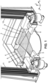
- Fig. 1 shows an example of a radiology apparatus dedicated to performance of a radiology method, in which there is no vertical gap implemented between first and second vertical scanning, both first and second vertical scanning including collimation tunnels upstream the detectors, resulting in a still too high cross-scattering level.
- Patient will be in weight bearing position, which means patient will be standing vertically and not lying horizontally. Scanning will be performed in the vertical direction Z. Indeed, there will be both a frontal scanning giving a frontal image in the X direction and a lateral scanning giving a lateral image in the Y direction.
- the radiology apparatus comprises two vertical slides 11 and 12.
- First vertical slide 11 is disposed for performing the frontal vertical scanning
- second vertical slide 12 is disposed for performing the lateral vertical scanning.
- Frontal vertical scanning will be performed along first vertical slide 11, whereas lateral vertical scanning will be performed along second vertical slide 12.
- first vertical slide 11 will be translated first detection chain whereas along second vertical slide 12 will be translated second detection chain.
- First detection chain comprises a first radiation source 1 associated to a first collimator 5 to narrow emitted beam 9 toward patient organ.
- the beam 9 After going through patient organ, not represented here for clarity reasons, the beam 9 enters in the first collimation tunnel 7 before reaching the sensitive surface of the first detector 3. Part of beam 9 is cross-scattered toward entering in the second collimation tunnel 8 before reaching the sensitive surface of the second detector 4.
- the frontal image of patient organ After end of first scanning, at the output of first detector 3 there is a first image, the frontal image of patient organ.
- the height of beam 9 considered is very small since it is the height of the beam 9 which will enter the first collimation tunnel 7 before reaching the sensitive surface of the first detector 3. Beam 9 may practically be considered as a planar beam.
- Second detection chain comprises a second radiation source 2 associated to a second collimator 6 to narrow emitted beam 10 toward patient organ.
- the beam 10 After going through patient organ, not represented here for clarity reasons, the beam 10 enters in the second collimation tunnel 8 before reaching the sensitive surface of the second detector 4. Part of beam 10 is cross-scattered toward entering in the first collimation tunnel 7 before reaching the sensitive surface of the first detector 3.
- the output of second detector 4 After end of second scanning, at the output of second detector 4 there is a second image, the lateral image of patient organ.
- the height of beam 10 considered is very small since it is the height of the beam 10 which will enter the second collimation tunnel 8 before reaching the sensitive surface of the second detector 4. Beam 10 may practically be considered as a planar beam.
- Either the tunnel collimations 7 and 8 are quite wide and the level of cross-scattering is too high, at least for overweight or obese patients, at least for some organs, or the tunnel collimations 7 and 8 are very narrow and the level of cross-scattering becomes acceptable, at least for overweight or obese patients, at least for some organs, but at the expense of a too low received signal on the sensitive surfaces of detectors 3 and 4.
- Fig. 2 shows an example of a radiology apparatus dedicated to performance of a radiology method, in which there is a vertical gap which has been implemented between first and second vertical scanning, both first and second vertical scanning including collimation tunnels upstream the detectors, resulting in a drastically reduced cross-scattering level.
- beams 9 and 10 are not at the same height with respect to each other.
- the beam 9 emitted by the first source 1, being narrowly collimated by the first collimator 5, will no more deflect any substantial cross-scattered signal toward the second collimation tunnel 8 and the second detector 4, thanks to the vertical gap h.
- the beam 10 emitted by the second source 2, being narrowly collimated by the second collimator 6, will no more deflect any substantial cross-scattered signal toward the first collimation tunnel 7 and the first detector 3, thanks to the vertical gap h.
- Both first and second detection chains will perform their respective scanning by respectively vertically sliding along first and second vertical slides 11 and 12, of patient organ to be imaged, either top down or bottom up.
- Typical scanning speed may be about 7.5 cm per second, which makes, for a 190 cm height corresponding to 19000 lines, about 25 seconds of scanning time.
- Maximal scanning speed may be close to 30 cm per second, which makes, for a 190 cm height corresponding to 19000 lines, about 6.3 seconds of scanning time.
- Fig. 3 shows examples of different curves obtained in different experimental conditions when performing a radiology method, showing the scattered fraction of signal received by the detectors as a function of the vertical gap existing between first and second vertical scanning.
- a first curve C1 shows the scattered fraction, expressed in percentage, of signal received by the detectors, which is a useless portion of received signal, as a function of the vertical gap existing between first and second vertical scanning, expressed in mm.
- This curve C1 shows that the amount of scattered fraction is very high. This scattered fraction lowers a little bit for high values of vertical gap, for instance more than 10cm. In these conditions, improvement coming from the vertical gap only is limited.
- a second curve C2 shows the scattered fraction, expressed in percentage, of signal received by the detectors, which is a useless portion of received signal, as a function of the vertical gap existing between first and second vertical scanning, expressed in mm.
- This curve C2 shows that the amount of scattered fraction is quite high, but not that high as for the curve C1. Therefore, limiting the height of the sensitive surfaces of the detectors has as a consequence the reduction of this scattered fraction.
- This scattered fraction lowers substantially, but only for high values of vertical gap, for instance more than 10cm. In these conditions, improvement coming from the vertical gap only is still somewhat limited.
- a third curve C3 shows the scattered fraction, expressed in percentage, of signal received by the detectors, which is a useless portion of received signal, as a function of the vertical gap existing between first and second vertical scanning, expressed in mm.
- collimation tunnels located upstream the detectors. Those collimation tunnels present a depth having a value of 50mm. The value of the height of the sensitive surfaces of the detectors is 3mm. The value of the tension of the tube in the radiation sources is 120 kV. To simulate an overweight patient, a water bucket presenting a diameter of 40cm has been used.
- This curve C3 shows that the amount of scattered fraction becomes quite low, as soon as the vertical gap becomes substantial, even if still quite low. For instance, this scattered fraction is already quite low, less than 20%, as soon as the vertical gap becomes higher than 2cm. However, without any vertical gap, i.e. with a vertical gap value of 0mm, this scattered fraction is much higher, indeed more than 50%. With a height of sensitive surface of detectors of 6mm, this positive effect is still there, even if a bit less important.
- a fourth curve C4 shows the scattered fraction, expressed in percentage, of signal received by the detectors, which is a useless portion of received signal, as a function of the vertical gap existing between first and second vertical scanning, expressed in mm.
- collimation tunnels located upstream the detectors. Those collimation tunnels present a depth having a value of 50mm. The value of the height of the sensitive surfaces of the detectors is 3mm. The value of the tension of the tube in the radiation sources is 95 kV. To simulate a standard patient, a water bucket presenting a diameter of 30cm has been used.
- This curve C4 shows that the amount of scattered fraction is relatively low even in the absence of vertical gap, but becomes even lower, as soon as the vertical gap becomes substantial, even if still quite low. For instance, this scattered fraction drops from 15% to 5%, as soon as the vertical gap becomes higher than 2cm. With a height of sensitive surface of detectors of 6mm, this positive effect is still there, even if a bit less important.
- fourth curve C4 improvement coming from the vertical gap combined with collimation tunnels, appears to be better than either vertical gap alone or collimation tunnels alone, but this effect is much less for a standard patient, as represented on fourth curve C4, than for an overweight patient, as represented on third curve C3.
Landscapes
- Health & Medical Sciences (AREA)
- Life Sciences & Earth Sciences (AREA)
- Medical Informatics (AREA)
- Engineering & Computer Science (AREA)
- Radiology & Medical Imaging (AREA)
- Biomedical Technology (AREA)
- Biophysics (AREA)
- Nuclear Medicine, Radiotherapy & Molecular Imaging (AREA)
- Optics & Photonics (AREA)
- Pathology (AREA)
- Physics & Mathematics (AREA)
- High Energy & Nuclear Physics (AREA)
- Heart & Thoracic Surgery (AREA)
- Molecular Biology (AREA)
- Surgery (AREA)
- Animal Behavior & Ethology (AREA)
- General Health & Medical Sciences (AREA)
- Public Health (AREA)
- Veterinary Medicine (AREA)
- Apparatus For Radiation Diagnosis (AREA)
Description
- The invention relates to methods of radiography of an organ of a patient, as well as associated apparatus, in particular when the patient is an overweight or obese patient. In particular, this method of radiography is preferably a stereo-radiography method.
- The field of the invention deals with a double scanning, preferably stereo-radiographic, system and a method to optimize the radiation, preferably x-ray, scattering rejection and correction in order to acquire at least two simultaneous views, preferably frontal and lateral view images for low dose three dimensional reconstruction of an organ, preferably the skeleton, of patients for medical applications.
- This system and method are dedicated to be used within medical radiology devices including at least two radiation, preferably x-ray, transmissions based imaging capabilities. These capabilities will be based on for example at least an x-ray emission source emitting x-ray spectra having a higher energy comprised between 20keV and 200keV. The typical imaged object is a patient in weight bearing position.
- A scanning stereo-radiographic system such as the one described in
EP 2309462 demonstrated good capabilities to make simultaneous frontal and lateral images for three dimensional reconstruction of skeletal anatomical parts such as the rachis or pelvis with a dose reduction up to 600 compared to Computed Tomography scan, and also a dose reduction up to 10 for single view images compared to Computed Radiography or Digital Radiography systems. But the maximum available dose rate of this system has also become a growing limitation to produce enough clinical quality images of overweight and obese patients, all the more that overweight and obese patients are nowadays very common patients. - One important problem to make some good clinical quality radiology images on overweight and obese patients is the big amount of scattered x-rays created while the direct x-ray beam is much attenuated. Thus, the transmitted direct x-ray signal can become very small, typically 10-20 times lower, in comparison with the scattered x-ray signal in direct two dimensional imaging systems.
- Some scattering rejection grids are commonly used to solve this problem, but taken alone, their efficiency is not good enough, and therefore the dose on overweight and obese patients can become very high in order to get clinical quality images.
- A scanning stereo-radiographic system such as the one described in
EP 2309462 demonstrates an efficient scattered x-ray rejection using a very thin object and detector collimations. But the useful dose rate fraction to make the image becomes too small for overweight patients. Some of the reasons are the limited output power of x-ray tubes and the very small collimation apertures. - According to such a prior art, for example described in
EP 2309462 , there is described a radiology method performing vertical scanning. This radiology method used collimators located upstream detectors, thereby improving cross-scattering and self-scattering rejection. However, high rejection rate was achieved thanks to narrow collimation thereby at the expense of lowering much the level of received radiation signal on the sensitive surfaces of the detectors. Therefore, at least for some patient organs, when used with reasonably overweight patients, it was difficult, and when used with really overweight or even obese patients, it was not possible, to find a good compromise between a high rate of scattering rejection and simultaneously a sufficient level of received radiation signal on the sensitive surfaces of the detectors. - A system to tune the aperture of the collimation according to the patient morphology such as the one described in another prior art, for example described in
WO 2011/138632 , could be used to enhance the ability to make clinical quality images on overweight patients of the scanning stereo-radiographic system described inEP 2309462 . - But, in this case, the output power of the x-ray tube and available collimation aperture of the detector would not be enough to cover the whole growing population of the varied morphologies among overweight and obese patients. The aperture limitation will be directly linked with the loss of spatial resolution of the detector and the amount of scattered x-ray coming from both x-ray imaging frontal and lateral views. The use of coplanar simultaneous frontal and lateral x-ray views will create a specific problem of cross-scattering in addition to the self-scattering pollution of each view.
- The object of the present invention is to alleviate at least partly the above mentioned drawbacks.
- More particularly, the invention aims at providing for a radiology method which allows, for all or most of types of patient organ, for all or most types of patient morphology, including overweight and preferably obese patients, for simultaneously achieving both a received signal level on sensitive surfaces of detectors sufficiently high and a cross-scattering rejection rate sufficiently high, so as to get a good signal to noise ratio and a good image quality.
- Therefore, the invention provides for a vertical gap between first and second vertical scanning reducing, preferably drastically reducing with the help of collimation tunnels located upstream detectors, at least the cross-scattering between first and second images.
- Embodiments of the invention are dedicated to enhance greatly the capability to make improved and good clinical quality images of simultaneous frontal and lateral views on standard patients and on overweight and obese patients, improving both spatial resolution, Signal to Noise Ratio and contrast of images while simultaneously reducing the image quality loss due to cross-scattered and self-scattered radiation, preferably x-ray radiation.
- This object is achieved with a method of radiography of an organ of a patient, comprising: a first vertical scanning of said organ by a first radiation source and a first detector cooperating to make a first two dimensional image of said organ, a second vertical scanning of said organ by a second radiation source and a second detector cooperating to make a second two dimensional image of said organ, said first vertical scanning and said second vertical scanning being performed synchronously, said first and second images viewing said organ of said patient according to different angles of incidence, wherein said method of radiography is performed with an overweight patient or with an obese patient, and wherein a first collimation tunnel is located upstream said first detector, a second collimation tunnel is located upstream said second detector, there is a vertical gap between on the one hand said first source and detector and on the other hand said second source and detector, such that said first vertical scanning and said second vertical scanning are performed synchronously but with a time shift in between, so as to reduce cross-scattering between said first and second images.
- When the cross-scattering level is not that high or when one can afford a high vertical gap, not being limited by a too low threshold for the total height of the apparatus, this object will also be achieved with a method of radiography of an organ of a patient, comprising: a first vertical scanning of said organ by a first radiation source and a first detector cooperating to make a first two dimensional image of said organ, a second vertical scanning of said organ by a second radiation source and a second detector cooperating to make a second two dimensional image of said organ, said first vertical scanning and said second vertical scanning being performed synchronously, said first and second images viewing said organ of said patient according to different angles of incidence, wherein there is a vertical gap between on the one hand said first source and detector and on the other hand said second source and detector, such that said first vertical scanning and said second vertical scanning are performed synchronously but with a time shift in between, so as to reduce cross-scattering between said first and second images.
- The time shift corresponds to said second vertical scanning arriving at each height of said organ after said first vertical scanning, with a given delay, or vice-versa.
- Different angles of incidence correspond to different directions (which are then not parallel), as for example two perpendicular directions, corresponding for example to a frontal view and to a lateral view of patient organ.
- This object is still achieved with a radiography apparatus comprising: a first radiation source and a first detector cooperating to make a first two dimensional image of an organ of a patient, by performing a first vertical scan of said organ of said patient, a second radiation source and a second detector cooperating to make a second two dimensional image of said organ of said patient, by performing a second vertical scan of said organ of said patient, said sources and said detectors cooperating so as to perform said first vertical scanning and said second vertical scanning synchronously, said first and second images viewing said organ of said patient according to different angles of incidence, wherein there is a vertical gap between on the one hand said first source and detector and on the other hand said second source and detector, such that said first vertical scanning and said second vertical scanning are performed synchronously but with a time shift in between, so as to reduce cross-scattering between said first and second images.
- Preferred embodiments comprise one or more of the following features, which can be taken separately or together, either in partial combination or in full combination, in combination with either object of the invention previously presented.
- Preferably, said method of radiography is performed with an overweight patient or with an obese patient.
- The method of radiography according to the invention is all the more interesting that the cross-scattering level is high. Therefore, with overweight or even obese patient, the cross-scattering level being quite high, this method of radiography becomes very interesting.
- Preferably, a collimation tunnel is located upstream each detector so as to further reduce cross-scattering on each image.
- Preferably, there are a first collimation tunnel located upstream said first detector so as to further reduce cross-scattering between said first and second images, and a second collimation tunnel located upstream said second detector so as to further reduce cross-scattering between said first and second images.
- That way, the cross-scattering level is further reduced because of the cooperation between the vertical gap of both radiation beams and the effective aperture reduction of both detectors. Indeed, by reducing the effective aperture of both detectors, the effect of the vertical gap between both beams is amplified, and a limited vertical gap will already result in an important cross-scattering level drop.
- Preferably, said collimation tunnel has a depth of more than 20mm, preferably more than 40mm.
- The longer the depth of the collimation tunnel is, the better the reduction of cross-scattering level is.
- Preferably, said vertical gap is less than 100 mm, preferably less than 80mm, more preferably less than 60mm.
- The shorter the depth of the collimation tunnel, the more important the available space for the patient within the cabin and the most useful the scanned width on the patient.
- Therefore a compromise has been found between on the one hand the reduction of cross-scattering level and on the other hand raising the useful part of the scanned width on the patient as well as maintaining a sufficiently important available space for the patient within the cabin. This compromise ranges from 20mm to 100mm, and an even better compromise ranges from 40mm to 60mm.
- There is also an interaction between the value of the vertical gap and the depth of the collimation tunnels by the detectors. So, these compromises are all the better that the vertical gap best ranges disclosed by the invention are used.
- Preferably, no scattering rejection grid is located upstream any detector.
- The disposition of collimation tunnels upstream detectors not only reduces cross-scattering between first and second images, but also reduces by the way self-scattering on both first and second images, thereby allowing for removing usually existing scattering rejection grids located upstream detectors. That way, presence of collimation tunnels upstream detectors allows for a triple benefit which is, first reducing cross-scattering, second reducing self-scattering, and third removing scattering rejection grids.
- Preferably, said vertical gap is more than the height of the sensitive surface of any of the detectors, preferably more than twice said height, more preferably more than four times said height.
- That way, the big size of the vertical gap relatively to the vertical size of the sensitive surface of the detectors will ensure that very little cross-scattering between first and second images happen indeed.
- Preferably, said vertical gap is more than 10 mm, preferably more than 20mm, more preferably more than 30mm.
- The bigger the vertical gap, the better the reduction of cross-scattering level.
- Preferably, said vertical gap is less than 100mm, and more preferably less than 60mm, having for example a preferred range from 20mm to 50mm, so that the delay between both vertical scanning is limited, so that the patient may not move significantly during this delay, so that a good correspondence between both first and second images is kept, so that a good quality of the global three dimensional reconstruction from both first and second images is kept.
- Preferably, a height of the sensitive surface of both detectors ranges from 2mm to 8mm, preferably ranges from 3mm to 6mm.
- That way, a good compromise, between a sufficient effective aperture of the detectors to ensure a sufficient level of signal received by detectors and a not too important effective aperture of the detectors to avoid a too high level of cross-scattering between first and second images, is met.
- Preferably, said vertical gap is fixed.
- In this embodiment, simplicity of the radiology mechanism required to allow for this synchronous although timely shifted scanning prevails.
- Preferably, said vertical gap is tunable.
- Preferably, said vertical gap is tunable according to patient morphology and/or according to patient organ.
- Preferably, said vertical gap is tunable according to respective effective apertures of said sources and according to respective effective apertures of said detectors, which said effective apertures are in turn tunable according to patient morphology and/or according to patient organ.
- In this other embodiment, flexibility of the radiology method performance, useful to cover many different possible situations with respect to patient morphology as well as with respect to patient organ, prevails.
- Preferably, said vertical gap does not exist at the very beginning of said first vertical scanning, but does exist at the very beginning of said second vertical scanning, and said vertical gap does not exist at the very end of said second vertical scanning, but does exist at the very end of said first vertical scanning.
- In this embodiment, both first and second vertical scanning follow exactly the same vertical course but follow it with a delay between each other. When not in use, the first source and detector on one side and the second source and detector on the other side, are both at the same vertical height. There is then the advantage of keeping lower the total required height for the global required vertical course which is equal to each one of the courses needed for the first and second vertical scanning. This way, the global height of the required moving mechanism, as well as the total height of the radiology apparatus, will be lower.
- Preferably, said vertical gap does always exist, even when neither said first vertical scanning nor said second vertical scanning are performed.
- In this other embodiment, both first and second vertical scanning follow the same vertical course only on major part of it, neither at the very beginning nor at the very end; besides, they follow it with a delay between each other. When not in use, the first source and detector on one side and the second source and detector on the other side, are not at the same vertical height. There is then the advantage of allowing for a mechanically simpler system to ensure a permanent vertical gap between the first source and detector on one side and the second source and detector on the other side. This way, the structure of the global required moving mechanism, as well as the structure of the whole radiology apparatus, will be simpler.
- Preferably, said patient morphology is chosen by a user of said method of radiography, preferably among a discrete number of choices.
- In this embodiment, choosing the type of patient morphology, as well as the type of patient organ, is let to the practitioner. This manual choice makes the whole system simpler, but requires a supplementary step from the practitioner, and may be the cause of a possible although improbable error.
- Preferably, said patient morphology is determined by a scout view scanning at a reduced level of radiation.
- In this other embodiment, choosing the type of patient morphology is performed automatically by using a kind of preview scanning at very low radiation dose. This automatic choice makes the whole system a bit more sophisticated, but avoids a supplementary step from the practitioner thereby making the system as a whole more secure, an error from the practitioner remaining always a possibility even if mostly improbable.
- Besides, making available a scout view allows for not only choosing the type of patient morphology via his thickness, but also his maximal thickness at each vertical height and for each image of the organ. Thereby, not only can tension and filtering function be chosen, but also the value of the current within the tubes of the sources.
- Preferably, said detectors are geometrically linear detectors, and said detectors are preferably geometrically multi-lines linear detectors. A geometrically linear detector is a detector having a single row or several rows of aligned elementary detection units. A geometrically multi-lines linear detector is a detector having several, at least two, parallel rows of aligned elementary detection units. The multi-lines linear detector may have an output signal which is either a linear function of its input signal or a nonlinear function of its input signal.
- That way, both the scanning image pixels dynamics and the image signal to noise ratios are improved. Yet, performing the considered vertical scanning with one line detectors, this single line being in a horizontal plan, remains possible.
- The used detectors present a few detection lines, typically 1 up to 100 lines, that can be used to acquire some frame images or can be summed according to a specified TDS (Time Delay Summation) or TDI (Time Delay Integration) speed in order to get a higher scanning image pixels dynamics and Signal to Noise Ratio. The effective aperture of such a detector is therefore higher than a single line detector, typically ranging from 0.1 up to 10 mm. This feature of TDS or TDI mode often provides a significant improvement in clinical quality image in comparison to detectors equipped with only one detection line for the same x-ray source output power. Other types of detectors can be used too, like for example 2D detectors. The detector may be either a solid or a gaseous detector, whether 1D or 2D detector.
- Preferably, collimators are located downstream said sources.
- That way, making the emitted radiation beams more collimated, that is more directional, the global level of scattering, either cross-scattering or self-scattering, may be further reduced.
- Preferably, said first and second images are perpendicular views of said organ, and are preferably frontal and lateral views.
- Therefore, a more reliable three dimensional modelling of the patient organ may be reconstructed from both these first and second images.
- Preferably, said radiation sources are x-ray sources and said detectors are x-ray detectors.
- Cross-scattering and self-scattering are particularly high with x-ray radiation, making the radiology method according to the invention, all the more interesting.
- Cross-scattering between first and second images is the scattering on one image which comes from a signal dedicated to the other image. More precisely, radiation emitted by first source and scattered by patient organ in the specific direction which brings it on the sensitive surface of second detector, instead of first detector, is cross-scattered signal. The same way, radiation emitted by second source and scattered by patient organ in the specific direction which brings it on the sensitive surface of first detector, instead of second detector, is cross-scattered signal. These cross-scattered signals raise the noise level and therefore deteriorate the signal to noise ratio. Moreover, the cross-scattering deteriorates the spatial resolution, the contrast, the detection quantum efficiency (DQE) and other parameters.
- Self-scattering on an image is the scattering on this image which comes from a signal dedicated to this image. More precisely, radiation emitted by first source and scattered by patient organ in the specific direction which brings it on the sensitive surface of first detector, as well as radiation scattered by the first detector itself, is self-scattered signal. The same way, radiation emitted by second source and scattered by patient organ in the specific direction which brings it on the sensitive surface of second detector, as well as radiation scattered by the second detector itself, is self-scattered signal. This self-scattered signal raises the noise level and therefore deteriorates the signal to noise ratio. Moreover, the self-scattering deteriorates the spatial resolution, the contrast, the detection quantum efficiency (DQE) and other parameters.
- Further features and advantages of the invention will appear from the following description of embodiments of the invention, given as nonlimiting examples, with reference to the accompanying drawings listed hereunder.
-
-
Fig. 1 shows an example of a radiology apparatus dedicated to performance of a radiology method, in which there is no vertical gap implemented between first and second vertical scanning, both first and second vertical scanning including collimation tunnels upstream the detectors, resulting in a still too high cross-scattering level. -
Fig. 2 shows an example of a radiology apparatus dedicated to performance of a radiology method, in which there is a vertical gap which has been implemented between first and second vertical scanning, both first and second vertical scanning including collimation tunnels upstream the detectors, resulting in a drastically reduced cross-scattering level. -
Fig. 3 shows examples of different curves obtained in different experimental conditions when performing a radiology method, showing the scattered fraction of signal received by the detectors as a function of the vertical gap existing between first and second vertical scanning. -
Fig. 1 shows an example of a radiology apparatus dedicated to performance of a radiology method, in which there is no vertical gap implemented between first and second vertical scanning, both first and second vertical scanning including collimation tunnels upstream the detectors, resulting in a still too high cross-scattering level. - Patient will be in weight bearing position, which means patient will be standing vertically and not lying horizontally. Scanning will be performed in the vertical direction Z. Indeed, there will be both a frontal scanning giving a frontal image in the X direction and a lateral scanning giving a lateral image in the Y direction.
- The radiology apparatus comprises two
vertical slides vertical slide 11 is disposed for performing the frontal vertical scanning, whereas secondvertical slide 12 is disposed for performing the lateral vertical scanning. Frontal vertical scanning will be performed along firstvertical slide 11, whereas lateral vertical scanning will be performed along secondvertical slide 12. - Along first
vertical slide 11 will be translated first detection chain whereas along secondvertical slide 12 will be translated second detection chain. - First detection chain comprises a first radiation source 1 associated to a first collimator 5 to narrow emitted
beam 9 toward patient organ. After going through patient organ, not represented here for clarity reasons, thebeam 9 enters in thefirst collimation tunnel 7 before reaching the sensitive surface of thefirst detector 3. Part ofbeam 9 is cross-scattered toward entering in thesecond collimation tunnel 8 before reaching the sensitive surface of thesecond detector 4. After end of first scanning, at the output offirst detector 3 there is a first image, the frontal image of patient organ. The height ofbeam 9 considered is very small since it is the height of thebeam 9 which will enter thefirst collimation tunnel 7 before reaching the sensitive surface of thefirst detector 3.Beam 9 may practically be considered as a planar beam. - Second detection chain comprises a
second radiation source 2 associated to asecond collimator 6 to narrow emittedbeam 10 toward patient organ. After going through patient organ, not represented here for clarity reasons, thebeam 10 enters in thesecond collimation tunnel 8 before reaching the sensitive surface of thesecond detector 4. Part ofbeam 10 is cross-scattered toward entering in thefirst collimation tunnel 7 before reaching the sensitive surface of thefirst detector 3. After end of second scanning, at the output ofsecond detector 4 there is a second image, the lateral image of patient organ. The height ofbeam 10 considered is very small since it is the height of thebeam 10 which will enter thesecond collimation tunnel 8 before reaching the sensitive surface of thesecond detector 4.Beam 10 may practically be considered as a planar beam. - Although a substantial part of cross-scattered signal is rejected, thanks to the presence of the
collimation tunnels detectors detectors - Either the tunnel collimations 7 and 8 are quite wide and the level of cross-scattering is too high, at least for overweight or obese patients, at least for some organs, or the tunnel collimations 7 and 8 are very narrow and the level of cross-scattering becomes acceptable, at least for overweight or obese patients, at least for some organs, but at the expense of a too low received signal on the sensitive surfaces of
detectors -
Fig. 2 shows an example of a radiology apparatus dedicated to performance of a radiology method, in which there is a vertical gap which has been implemented between first and second vertical scanning, both first and second vertical scanning including collimation tunnels upstream the detectors, resulting in a drastically reduced cross-scattering level. - Here beams 9 and 10 are not at the same height with respect to each other. There is a vertical gap h between the heights of the middle plans of the
beams detectors collimation tunnels - The
beam 9 emitted by the first source 1, being narrowly collimated by the first collimator 5, will no more deflect any substantial cross-scattered signal toward thesecond collimation tunnel 8 and thesecond detector 4, thanks to the vertical gap h. - The
beam 10 emitted by thesecond source 2, being narrowly collimated by thesecond collimator 6, will no more deflect any substantial cross-scattered signal toward thefirst collimation tunnel 7 and thefirst detector 3, thanks to the vertical gap h. - Both first and second detection chains will perform their respective scanning by respectively vertically sliding along first and second
vertical slides - Typical scanning speed may be about 7.5 cm per second, which makes, for a 190 cm height corresponding to 19000 lines, about 25 seconds of scanning time.
- Maximal scanning speed may be close to 30 cm per second, which makes, for a 190 cm height corresponding to 19000 lines, about 6.3 seconds of scanning time.
-
Fig. 3 shows examples of different curves obtained in different experimental conditions when performing a radiology method, showing the scattered fraction of signal received by the detectors as a function of the vertical gap existing between first and second vertical scanning. - A first curve C1 shows the scattered fraction, expressed in percentage, of signal received by the detectors, which is a useless portion of received signal, as a function of the vertical gap existing between first and second vertical scanning, expressed in mm.
- There are no collimation tunnels located upstream the detectors. The value of the height of the sensitive surfaces of the detectors is 6mm. The value of the tension of the tube in the radiation sources is 120 kV. To simulate an overweight patient, a water bucket presenting a diameter of 40cm has been used.
- This curve C1 shows that the amount of scattered fraction is very high. This scattered fraction lowers a little bit for high values of vertical gap, for instance more than 10cm. In these conditions, improvement coming from the vertical gap only is limited.
- A second curve C2 shows the scattered fraction, expressed in percentage, of signal received by the detectors, which is a useless portion of received signal, as a function of the vertical gap existing between first and second vertical scanning, expressed in mm.
- There are no collimation tunnels located upstream the detectors. The value of the height of the sensitive surfaces of the detectors is 3mm. The value of the tension of the tube in the radiation sources is 120 kV. To simulate an overweight patient, a water bucket presenting a diameter of 40cm has been used.
- This curve C2 shows that the amount of scattered fraction is quite high, but not that high as for the curve C1. Therefore, limiting the height of the sensitive surfaces of the detectors has as a consequence the reduction of this scattered fraction. This scattered fraction lowers substantially, but only for high values of vertical gap, for instance more than 10cm. In these conditions, improvement coming from the vertical gap only is still somewhat limited.
- A third curve C3 shows the scattered fraction, expressed in percentage, of signal received by the detectors, which is a useless portion of received signal, as a function of the vertical gap existing between first and second vertical scanning, expressed in mm.
- There are collimation tunnels located upstream the detectors. Those collimation tunnels present a depth having a value of 50mm. The value of the height of the sensitive surfaces of the detectors is 3mm. The value of the tension of the tube in the radiation sources is 120 kV. To simulate an overweight patient, a water bucket presenting a diameter of 40cm has been used.
- This curve C3 shows that the amount of scattered fraction becomes quite low, as soon as the vertical gap becomes substantial, even if still quite low. For instance, this scattered fraction is already quite low, less than 20%, as soon as the vertical gap becomes higher than 2cm. However, without any vertical gap, i.e. with a vertical gap value of 0mm, this scattered fraction is much higher, indeed more than 50%. With a height of sensitive surface of detectors of 6mm, this positive effect is still there, even if a bit less important.
- In these conditions of third curve C3, improvement coming from the vertical gap combined with collimation tunnels, appears to be much better than either vertical gap alone or collimation tunnels alone.
- A fourth curve C4 shows the scattered fraction, expressed in percentage, of signal received by the detectors, which is a useless portion of received signal, as a function of the vertical gap existing between first and second vertical scanning, expressed in mm.
- There are collimation tunnels located upstream the detectors. Those collimation tunnels present a depth having a value of 50mm. The value of the height of the sensitive surfaces of the detectors is 3mm. The value of the tension of the tube in the radiation sources is 95 kV. To simulate a standard patient, a water bucket presenting a diameter of 30cm has been used.
- This curve C4 shows that the amount of scattered fraction is relatively low even in the absence of vertical gap, but becomes even lower, as soon as the vertical gap becomes substantial, even if still quite low. For instance, this scattered fraction drops from 15% to 5%, as soon as the vertical gap becomes higher than 2cm. With a height of sensitive surface of detectors of 6mm, this positive effect is still there, even if a bit less important.
- In these conditions of fourth curve C4, improvement coming from the vertical gap combined with collimation tunnels, appears to be better than either vertical gap alone or collimation tunnels alone, but this effect is much less for a standard patient, as represented on fourth curve C4, than for an overweight patient, as represented on third curve C3.
- It can be deduced from curves C1 to C4, first that the combination of vertical gap and of collimation tunnels is very interesting and much better to reduce the scattered fraction that the separated effects of vertical gap alone and of collimation tunnels alone, and second that this scattered fraction reduction is all the more important that the patient is overweight.
Claims (15)
- Method of radiography of an organ of a patient, comprising:- a first vertical scanning of said organ by a first radiation source (1) and a first detector (3) cooperating to make a first two dimensional image of said organ,- a second vertical scanning of said organ by a second radiation source (2) and a second detector (4) cooperating to make a second two dimensional image of said organ,- said first vertical scanning and said second vertical scanning being performed synchronously,- said first and second images viewing said organ of said patient according to different angles of incidence,wherein there is a vertical gap (h) between on the one hand said first source (1) and detector (3) and on the other hand said second source (2) and detector (4), such that said first vertical scanning and said second vertical scanning are performed synchronously but with a time shift in between, so as to reduce cross-scattering between said first and second images.
- Method of radiography according to claim 1, wherein said method of radiography is performed with an overweight patient or with an obese patient.
- Method of radiography according to claims 1 or 2, wherein a collimation tunnel (7, 8) is located upstream each detector (3, 4) so as to further reduce cross-scattering on each image.
- Method of radiography according to claim 3, wherein said collimation tunnel (7, 8) has a depth of more than 20mm, preferably more than 40mm.
- Method of radiography according to claim 3 or 4, wherein no scattering rejection grid is located upstream any detector (3, 4).
- Method of radiography according to any of preceding claims, wherein said vertical gap (h) is more than the height of the sensitive surface of any of the detectors (3, 4), preferably more than twice said height, more preferably more than four times said height, and/or wherein said vertical gap (h) is more than 10 mm, preferably more than 20mm, more preferably more than 30mm, and/or wherein said vertical gap (h) is less than 100 mm, preferably less than 80mm, more preferably less than 60mm. and/or wherein a height of the sensitive surface of both detectors ranges from 2mm to 8mm, preferably ranges from 3mm to 6mm.
- Method of radiography according to any of claims 1 to 6, wherein said vertical gap (h) is fixed.
- Method of radiography according to any of claims 1 to 6, wherein said vertical gap (h) is tunable, preferably wherein said vertical gap (h) is tunable according to patient morphology and/or according to patient organ, more preferably wherein said vertical gap (h) is tunable according to respective effective apertures of said sources (1, 2) and according to respective effective apertures of said detectors (3, 4), which said effective apertures are in turn tunable according to patient morphology and/or according to patient organ.
- Method of radiography according to any of claims 1 to 8, wherein:- said vertical gap (h) does not exist at the very beginning of said first vertical scanning, but does exist at the very beginning of said second vertical scanning,- said vertical gap (h) does not exist at the very end of said second vertical scanning, but does exist at the very end of said first vertical scanning,or wherein said vertical gap (h) does always exist, even when neither said first vertical scanning nor said second vertical scanning are performed.
- Method of radiography according to any of claims 1 to 9, wherein said patient morphology is chosen by a user of said method of radiography, preferably among a discrete number of choices, or wherein said patient morphology is determined by a scout view scanning at a reduced level of radiation.
- Method of radiography according to any of preceding claims, wherein said detectors (3, 4) are geometrically linear detectors (3, 4), and said detectors (3, 4) are preferably geometrically multi-lines linear detectors (3, 4).
- Method of radiography according to any of preceding claims, wherein collimators (5, 6) are located downstream said sources (1, 2).
- Method of radiography according to any of preceding claims, wherein said first and second images are perpendicular views of said organ, and are preferably frontal and lateral views.
- Method of radiography according to any of preceding claims, wherein said radiation sources (1, 2) are x-ray sources (1, 2) and said detectors (3, 4) are x-ray detectors (3, 4).
- Radiography apparatus comprising:- a first radiation source (1) and a first detector (3) cooperating to make a first two dimensional image of an organ of a patient, by performing a first vertical scan of said organ of said patient,- a second radiation source (2) and a second detector (4) cooperating to make a second two dimensional image of said organ of said patient, by performing a second vertical scan of said organ of said patient,- said sources (1, 2) and said detectors (3, 4) cooperating so as to perform said first vertical scanning and said second vertical scanning synchronously,- said first and second images viewing said organ of said patient according to different angles of incidence,wherein there is a vertical gap (h) between on the one hand said first source (1) and detector (3) and on the other hand said second source (2) and detector (4), such that said first vertical scanning and said second vertical scanning are performed synchronously but with a time shift in between, so as to reduce cross-scattering between said first and second images,
preferably wherein it also comprises:- a first collimation tunnel (7) located upstream said first detector (3) so as to further reduce cross-scattering between said first and second images,- a second collimation tunnel (8) located upstream said second detector (4) so as to further reduce cross-scattering between said first and second images.
Applications Claiming Priority (1)
| Application Number | Priority Date | Filing Date | Title |
|---|---|---|---|
| PCT/IB2016/000273 WO2017137792A1 (en) | 2016-02-10 | 2016-02-10 | Method of radiography of an organ of a patient |
Publications (3)
| Publication Number | Publication Date |
|---|---|
| EP3413800A1 EP3413800A1 (en) | 2018-12-19 |
| EP3413800C0 EP3413800C0 (en) | 2023-12-27 |
| EP3413800B1 true EP3413800B1 (en) | 2023-12-27 |
Family
ID=55629062
Family Applications (1)
| Application Number | Title | Priority Date | Filing Date |
|---|---|---|---|
| EP16711889.2A Active EP3413800B1 (en) | 2016-02-10 | 2016-02-10 | Method of radiography of an organ of a patient |
Country Status (5)
| Country | Link |
|---|---|
| US (1) | US10702227B2 (en) |
| EP (1) | EP3413800B1 (en) |
| JP (1) | JP6779303B2 (en) |
| CN (1) | CN109069090B (en) |
| WO (1) | WO2017137792A1 (en) |
Families Citing this family (3)
| Publication number | Priority date | Publication date | Assignee | Title |
|---|---|---|---|---|
| JP6779303B2 (en) * | 2016-02-10 | 2020-11-04 | イオス・イメージング | How to X-ray the patient's organs |
| CN115515499B (en) * | 2019-11-05 | 2025-07-08 | Eos成像公司 | Radiological imaging method and radiological apparatus with vertical scanning of 2 radiation sources |
| US12207959B2 (en) * | 2019-11-14 | 2025-01-28 | Eos Imaging | Radiological imaging method |
Family Cites Families (30)
| Publication number | Priority date | Publication date | Assignee | Title |
|---|---|---|---|---|
| EP0229308B1 (en) * | 1985-12-20 | 1991-06-05 | Siemens Aktiengesellschaft | Diagnostic dental x-ray apparatus for carrying out panoramic tomography of a patient's jaw |
| JPH0324300U (en) | 1989-07-19 | 1991-03-13 | ||
| JPH05168616A (en) * | 1991-12-26 | 1993-07-02 | Toshiba Corp | X-ray CT system |
| DE69425762T2 (en) * | 1993-06-09 | 2001-04-26 | Wisconsin Alumni Research Foundation, Madison | Radiation therapy system |
| US6104780A (en) | 1997-11-24 | 2000-08-15 | Oec Medical Systems, Inc. | Mobile bi-planar fluoroscopic imaging apparatus |
| US5991357A (en) | 1997-12-16 | 1999-11-23 | Analogic Corporation | Integrated radiation detecting and collimating assembly for X-ray tomography system |
| JP2003522583A (en) * | 2000-02-15 | 2003-07-29 | フィリップス メディカル システムズ テクノロジーズ リミテッド | Clinical screening CT system |
| FR2810769B1 (en) | 2000-06-23 | 2002-10-11 | Biospace Instr | RADIOGRAPHIC IMAGING METHOD AND DEVICE FOR THREE-DIMENSIONAL LOW-DOSE IRRADIATION RECONSTITUTION |
| CN100337593C (en) * | 2000-09-28 | 2007-09-19 | 菲利浦医疗系统技术有限公司 | Large-coverage computed tomography scanner for temporal coherence |
| US7085343B2 (en) | 2001-10-18 | 2006-08-01 | Kabushiki Kaisha Toshiba | X-ray computed tomography apparatus |
| WO2003101301A1 (en) * | 2002-06-03 | 2003-12-11 | Hitachi Medical Corporation | Multi-slice x-ray ct device |
| DE10302565A1 (en) * | 2003-01-22 | 2004-08-12 | Siemens Ag | Computer tomography unit has at least two beam detector combinations the measurement field areas of which can be set to different sizes |
| JP2006528017A (en) | 2003-07-22 | 2006-12-14 | コーニンクレッカ フィリップス エレクトロニクス エヌ ヴィ | Radiation mask for 2D CT detector |
| US7224764B2 (en) * | 2003-08-07 | 2007-05-29 | Xoran Technologies, Inc. | Stand-up CT scanner |
| US7639774B2 (en) * | 2003-12-23 | 2009-12-29 | General Electric Company | Method and apparatus for employing multiple axial-sources |
| US7542540B2 (en) * | 2005-07-15 | 2009-06-02 | Kabushiki Kaisha Toshiba | X-ray CT apparatus |
| SE529702C8 (en) * | 2006-03-21 | 2007-11-27 | Scanning-based detection of ionizing radiation by dual sources | |
| RU2009101943A (en) | 2006-06-22 | 2010-07-27 | Конинклейке Филипс Электроникс Н.В. (Nl) | CONTROL OF TRANSMISSION OF RADIATION OF TWO RENGTEN PIPES |
| JP5498788B2 (en) * | 2006-08-25 | 2014-05-21 | コーニンクレッカ フィリップス エヌ ヴェ | Multi-tube X-ray detection |
| US7806589B2 (en) | 2007-09-26 | 2010-10-05 | University Of Pittsburgh | Bi-plane X-ray imaging system |
| JP2009297314A (en) * | 2008-06-16 | 2009-12-24 | Ge Medical Systems Global Technology Co Llc | X-ray tomographic apparatus |
| CN201239150Y (en) * | 2008-07-31 | 2009-05-20 | 上海西门子医疗器械有限公司 | CT scanner |
| JP2010124832A (en) | 2008-11-25 | 2010-06-10 | Toshiba Corp | X-ray computerized tomographic apparatus and x-ray detector |
| US9245658B2 (en) | 2010-05-06 | 2016-01-26 | Eos Imaging | Imaging apparatus and method |
| CN103284734B (en) * | 2012-03-05 | 2015-07-22 | 上海联影医疗科技有限公司 | Method and device for correcting scattering influence in radiation imaging |
| DE102012204350B4 (en) * | 2012-03-20 | 2021-12-02 | Siemens Healthcare Gmbh | Method for energy calibration of quantum-counting X-ray detectors in a dual-source computer tomograph |
| DE102013203541A1 (en) * | 2013-03-01 | 2014-09-04 | Siemens Aktiengesellschaft | X-ray CT scan and dual source CT system |
| CN104095643A (en) | 2013-04-08 | 2014-10-15 | 上海联影医疗科技有限公司 | X-ray imaging device |
| JP6779303B2 (en) * | 2016-02-10 | 2020-11-04 | イオス・イメージング | How to X-ray the patient's organs |
| US11864940B2 (en) * | 2017-07-04 | 2024-01-09 | Eos Imaging | Method of radiography of an organ of a patient |
-
2016
- 2016-02-10 JP JP2018543105A patent/JP6779303B2/en active Active
- 2016-02-10 EP EP16711889.2A patent/EP3413800B1/en active Active
- 2016-02-10 WO PCT/IB2016/000273 patent/WO2017137792A1/en not_active Ceased
- 2016-02-10 US US16/076,660 patent/US10702227B2/en active Active
- 2016-02-10 CN CN201680084430.3A patent/CN109069090B/en active Active
Also Published As
| Publication number | Publication date |
|---|---|
| US20190046133A1 (en) | 2019-02-14 |
| JP2019504721A (en) | 2019-02-21 |
| EP3413800C0 (en) | 2023-12-27 |
| EP3413800A1 (en) | 2018-12-19 |
| CN109069090A (en) | 2018-12-21 |
| US10702227B2 (en) | 2020-07-07 |
| JP6779303B2 (en) | 2020-11-04 |
| CN109069090B (en) | 2022-09-13 |
| WO2017137792A1 (en) | 2017-08-17 |
Similar Documents
| Publication | Publication Date | Title |
|---|---|---|
| US10827992B2 (en) | Energy-discriminating photon-counting detector and the use thereof | |
| EP3680650B1 (en) | X-ray imaging system and method for correcting focal spot misalignment | |
| US6496557B2 (en) | Two-dimensional slot x-ray bone densitometry, radiography and tomography | |
| US7570736B2 (en) | Direct conversion energy discriminating CT detector with over-ranging correction | |
| US9087619B2 (en) | Apparatus for scatter reduction for CT imaging and method of fabricating same | |
| EP0244766A2 (en) | Dual energy imaging with kinestatic charge detector | |
| US20060104411A1 (en) | Direct conversion energy discriminating ct detector | |
| US20090147910A1 (en) | System and method for energy sensitive computed tomography | |
| EP4292537A2 (en) | Method of radiography of an organ of a patient | |
| US6332015B1 (en) | Radiographic diagnosis apparatus, radiographic diagnosis method, plate member, and position detecting method | |
| JP2006142009A (en) | Slot scanning configuration based on flat panel detector | |
| JP2020519872A (en) | Reference detector element combined with anti-scatter collimator | |
| US10702227B2 (en) | Method of radiography of an organ of a patient | |
| JPH06508055A (en) | A system that selectively forms images of materials | |
| US10307118B2 (en) | Method and device for the imaging scanning of a female breast in the context of digital projective mammography or tomosynthesis | |
| US7129498B2 (en) | Compact structural CT detector module | |
| KR102177991B1 (en) | Methods for 2-color radiography with laser-compton x-ray sources | |
| DE102023203780A1 (en) | Spectrally resolved X-ray imaging | |
| JP2018023671A (en) | Image processing apparatus, X-ray imaging apparatus, and image processing method | |
| Besson et al. | Multispectral single-scan lung imaging system: initial feasibility | |
| JP2008023386A (en) | Radiation detector |
Legal Events
| Date | Code | Title | Description |
|---|---|---|---|
| STAA | Information on the status of an ep patent application or granted ep patent |
Free format text: STATUS: UNKNOWN |
|
| STAA | Information on the status of an ep patent application or granted ep patent |
Free format text: STATUS: THE INTERNATIONAL PUBLICATION HAS BEEN MADE |
|
| PUAI | Public reference made under article 153(3) epc to a published international application that has entered the european phase |
Free format text: ORIGINAL CODE: 0009012 |
|
| STAA | Information on the status of an ep patent application or granted ep patent |
Free format text: STATUS: REQUEST FOR EXAMINATION WAS MADE |
|
| 17P | Request for examination filed |
Effective date: 20180808 |
|
| AK | Designated contracting states |
Kind code of ref document: A1 Designated state(s): AL AT BE BG CH CY CZ DE DK EE ES FI FR GB GR HR HU IE IS IT LI LT LU LV MC MK MT NL NO PL PT RO RS SE SI SK SM TR |
|
| AX | Request for extension of the european patent |
Extension state: BA ME |
|
| DAV | Request for validation of the european patent (deleted) | ||
| DAX | Request for extension of the european patent (deleted) | ||
| STAA | Information on the status of an ep patent application or granted ep patent |
Free format text: STATUS: EXAMINATION IS IN PROGRESS |
|
| 17Q | First examination report despatched |
Effective date: 20210922 |
|
| GRAP | Despatch of communication of intention to grant a patent |
Free format text: ORIGINAL CODE: EPIDOSNIGR1 |
|
| STAA | Information on the status of an ep patent application or granted ep patent |
Free format text: STATUS: GRANT OF PATENT IS INTENDED |
|
| INTG | Intention to grant announced |
Effective date: 20230724 |
|
| GRAS | Grant fee paid |
Free format text: ORIGINAL CODE: EPIDOSNIGR3 |
|
| GRAA | (expected) grant |
Free format text: ORIGINAL CODE: 0009210 |
|
| STAA | Information on the status of an ep patent application or granted ep patent |
Free format text: STATUS: THE PATENT HAS BEEN GRANTED |
|
| AK | Designated contracting states |
Kind code of ref document: B1 Designated state(s): AL AT BE BG CH CY CZ DE DK EE ES FI FR GB GR HR HU IE IS IT LI LT LU LV MC MK MT NL NO PL PT RO RS SE SI SK SM TR |
|
| REG | Reference to a national code |
Ref country code: GB Ref legal event code: FG4D |
|
| REG | Reference to a national code |
Ref country code: CH Ref legal event code: EP |
|
| REG | Reference to a national code |
Ref country code: DE Ref legal event code: R096 Ref document number: 602016084969 Country of ref document: DE |
|
| REG | Reference to a national code |
Ref country code: IE Ref legal event code: FG4D |
|
| U01 | Request for unitary effect filed |
Effective date: 20240123 |
|
| U07 | Unitary effect registered |
Designated state(s): AT BE BG DE DK EE FI FR IT LT LU LV MT NL PT SE SI Effective date: 20240131 |
|
| U20 | Renewal fee for the european patent with unitary effect paid |
Year of fee payment: 9 Effective date: 20240201 |
|
| PG25 | Lapsed in a contracting state [announced via postgrant information from national office to epo] |
Ref country code: GR Free format text: LAPSE BECAUSE OF FAILURE TO SUBMIT A TRANSLATION OF THE DESCRIPTION OR TO PAY THE FEE WITHIN THE PRESCRIBED TIME-LIMIT Effective date: 20240328 |
|
| PG25 | Lapsed in a contracting state [announced via postgrant information from national office to epo] |
Ref country code: ES Free format text: LAPSE BECAUSE OF FAILURE TO SUBMIT A TRANSLATION OF THE DESCRIPTION OR TO PAY THE FEE WITHIN THE PRESCRIBED TIME-LIMIT Effective date: 20231227 |
|
| PG25 | Lapsed in a contracting state [announced via postgrant information from national office to epo] |
Ref country code: GR Free format text: LAPSE BECAUSE OF FAILURE TO SUBMIT A TRANSLATION OF THE DESCRIPTION OR TO PAY THE FEE WITHIN THE PRESCRIBED TIME-LIMIT Effective date: 20240328 Ref country code: ES Free format text: LAPSE BECAUSE OF FAILURE TO SUBMIT A TRANSLATION OF THE DESCRIPTION OR TO PAY THE FEE WITHIN THE PRESCRIBED TIME-LIMIT Effective date: 20231227 |
|
| PG25 | Lapsed in a contracting state [announced via postgrant information from national office to epo] |
Ref country code: RS Free format text: LAPSE BECAUSE OF FAILURE TO SUBMIT A TRANSLATION OF THE DESCRIPTION OR TO PAY THE FEE WITHIN THE PRESCRIBED TIME-LIMIT Effective date: 20231227 Ref country code: NO Free format text: LAPSE BECAUSE OF FAILURE TO SUBMIT A TRANSLATION OF THE DESCRIPTION OR TO PAY THE FEE WITHIN THE PRESCRIBED TIME-LIMIT Effective date: 20240327 Ref country code: HR Free format text: LAPSE BECAUSE OF FAILURE TO SUBMIT A TRANSLATION OF THE DESCRIPTION OR TO PAY THE FEE WITHIN THE PRESCRIBED TIME-LIMIT Effective date: 20231227 |
|
| PG25 | Lapsed in a contracting state [announced via postgrant information from national office to epo] |
Ref country code: IS Free format text: LAPSE BECAUSE OF FAILURE TO SUBMIT A TRANSLATION OF THE DESCRIPTION OR TO PAY THE FEE WITHIN THE PRESCRIBED TIME-LIMIT Effective date: 20240427 |
|
| PG25 | Lapsed in a contracting state [announced via postgrant information from national office to epo] |
Ref country code: CZ Free format text: LAPSE BECAUSE OF FAILURE TO SUBMIT A TRANSLATION OF THE DESCRIPTION OR TO PAY THE FEE WITHIN THE PRESCRIBED TIME-LIMIT Effective date: 20231227 |
|
| PG25 | Lapsed in a contracting state [announced via postgrant information from national office to epo] |
Ref country code: SK Free format text: LAPSE BECAUSE OF FAILURE TO SUBMIT A TRANSLATION OF THE DESCRIPTION OR TO PAY THE FEE WITHIN THE PRESCRIBED TIME-LIMIT Effective date: 20231227 |
|
| PG25 | Lapsed in a contracting state [announced via postgrant information from national office to epo] |
Ref country code: SM Free format text: LAPSE BECAUSE OF FAILURE TO SUBMIT A TRANSLATION OF THE DESCRIPTION OR TO PAY THE FEE WITHIN THE PRESCRIBED TIME-LIMIT Effective date: 20231227 Ref country code: SK Free format text: LAPSE BECAUSE OF FAILURE TO SUBMIT A TRANSLATION OF THE DESCRIPTION OR TO PAY THE FEE WITHIN THE PRESCRIBED TIME-LIMIT Effective date: 20231227 Ref country code: RO Free format text: LAPSE BECAUSE OF FAILURE TO SUBMIT A TRANSLATION OF THE DESCRIPTION OR TO PAY THE FEE WITHIN THE PRESCRIBED TIME-LIMIT Effective date: 20231227 Ref country code: IS Free format text: LAPSE BECAUSE OF FAILURE TO SUBMIT A TRANSLATION OF THE DESCRIPTION OR TO PAY THE FEE WITHIN THE PRESCRIBED TIME-LIMIT Effective date: 20240427 Ref country code: CZ Free format text: LAPSE BECAUSE OF FAILURE TO SUBMIT A TRANSLATION OF THE DESCRIPTION OR TO PAY THE FEE WITHIN THE PRESCRIBED TIME-LIMIT Effective date: 20231227 |
|
| PG25 | Lapsed in a contracting state [announced via postgrant information from national office to epo] |
Ref country code: PL Free format text: LAPSE BECAUSE OF FAILURE TO SUBMIT A TRANSLATION OF THE DESCRIPTION OR TO PAY THE FEE WITHIN THE PRESCRIBED TIME-LIMIT Effective date: 20231227 |
|
| PG25 | Lapsed in a contracting state [announced via postgrant information from national office to epo] |
Ref country code: PL Free format text: LAPSE BECAUSE OF FAILURE TO SUBMIT A TRANSLATION OF THE DESCRIPTION OR TO PAY THE FEE WITHIN THE PRESCRIBED TIME-LIMIT Effective date: 20231227 |
|
| PG25 | Lapsed in a contracting state [announced via postgrant information from national office to epo] |
Ref country code: MC Free format text: LAPSE BECAUSE OF FAILURE TO SUBMIT A TRANSLATION OF THE DESCRIPTION OR TO PAY THE FEE WITHIN THE PRESCRIBED TIME-LIMIT Effective date: 20231227 |
|
| REG | Reference to a national code |
Ref country code: DE Ref legal event code: R097 Ref document number: 602016084969 Country of ref document: DE Ref country code: CH Ref legal event code: PL |
|
| PG25 | Lapsed in a contracting state [announced via postgrant information from national office to epo] |
Ref country code: CH Free format text: LAPSE BECAUSE OF NON-PAYMENT OF DUE FEES Effective date: 20240229 |
|
| PG25 | Lapsed in a contracting state [announced via postgrant information from national office to epo] |
Ref country code: CH Free format text: LAPSE BECAUSE OF NON-PAYMENT OF DUE FEES Effective date: 20240229 |
|
| PLBE | No opposition filed within time limit |
Free format text: ORIGINAL CODE: 0009261 |
|
| STAA | Information on the status of an ep patent application or granted ep patent |
Free format text: STATUS: NO OPPOSITION FILED WITHIN TIME LIMIT |
|
| 26N | No opposition filed |
Effective date: 20240930 |
|
| PG25 | Lapsed in a contracting state [announced via postgrant information from national office to epo] |
Ref country code: IE Free format text: LAPSE BECAUSE OF NON-PAYMENT OF DUE FEES Effective date: 20240210 |
|
| PG25 | Lapsed in a contracting state [announced via postgrant information from national office to epo] |
Ref country code: IE Free format text: LAPSE BECAUSE OF NON-PAYMENT OF DUE FEES Effective date: 20240210 |
|
| U20 | Renewal fee for the european patent with unitary effect paid |
Year of fee payment: 10 Effective date: 20250121 |
|
| PG25 | Lapsed in a contracting state [announced via postgrant information from national office to epo] |
Ref country code: CY Free format text: LAPSE BECAUSE OF FAILURE TO SUBMIT A TRANSLATION OF THE DESCRIPTION OR TO PAY THE FEE WITHIN THE PRESCRIBED TIME-LIMIT; INVALID AB INITIO Effective date: 20160210 |
|
| PG25 | Lapsed in a contracting state [announced via postgrant information from national office to epo] |
Ref country code: HU Free format text: LAPSE BECAUSE OF FAILURE TO SUBMIT A TRANSLATION OF THE DESCRIPTION OR TO PAY THE FEE WITHIN THE PRESCRIBED TIME-LIMIT; INVALID AB INITIO Effective date: 20160210 |
|
| PG25 | Lapsed in a contracting state [announced via postgrant information from national office to epo] |
Ref country code: TR Free format text: LAPSE BECAUSE OF FAILURE TO SUBMIT A TRANSLATION OF THE DESCRIPTION OR TO PAY THE FEE WITHIN THE PRESCRIBED TIME-LIMIT Effective date: 20231227 |
|
| U20 | Renewal fee for the european patent with unitary effect paid |
Year of fee payment: 11 Effective date: 20260121 |
|
| PGFP | Annual fee paid to national office [announced via postgrant information from national office to epo] |
Ref country code: GB Payment date: 20260219 Year of fee payment: 11 |