EP3413471A1 - Am noise cancellation in vehicles - Google Patents
Am noise cancellation in vehicles Download PDFInfo
- Publication number
- EP3413471A1 EP3413471A1 EP18170791.0A EP18170791A EP3413471A1 EP 3413471 A1 EP3413471 A1 EP 3413471A1 EP 18170791 A EP18170791 A EP 18170791A EP 3413471 A1 EP3413471 A1 EP 3413471A1
- Authority
- EP
- European Patent Office
- Prior art keywords
- port
- filter
- coefficients
- noise
- coupled
- Prior art date
- Legal status (The legal status is an assumption and is not a legal conclusion. Google has not performed a legal analysis and makes no representation as to the accuracy of the status listed.)
- Granted
Links
Images
Classifications
-
- H—ELECTRICITY
- H04—ELECTRIC COMMUNICATION TECHNIQUE
- H04B—TRANSMISSION
- H04B15/00—Suppression or limitation of noise or interference
- H04B15/005—Reducing noise, e.g. humm, from the supply
-
- G—PHYSICS
- G10—MUSICAL INSTRUMENTS; ACOUSTICS
- G10K—SOUND-PRODUCING DEVICES; METHODS OR DEVICES FOR PROTECTING AGAINST, OR FOR DAMPING, NOISE OR OTHER ACOUSTIC WAVES IN GENERAL; ACOUSTICS NOT OTHERWISE PROVIDED FOR
- G10K11/00—Methods or devices for transmitting, conducting or directing sound in general; Methods or devices for protecting against, or for damping, noise or other acoustic waves in general
- G10K11/16—Methods or devices for protecting against, or for damping, noise or other acoustic waves in general
- G10K11/175—Methods or devices for protecting against, or for damping, noise or other acoustic waves in general using interference effects; Masking sound
-
- H—ELECTRICITY
- H04—ELECTRIC COMMUNICATION TECHNIQUE
- H04B—TRANSMISSION
- H04B1/00—Details of transmission systems, not covered by a single one of groups H04B3/00 - H04B13/00; Details of transmission systems not characterised by the medium used for transmission
- H04B1/06—Receivers
- H04B1/10—Means associated with receiver for limiting or suppressing noise or interference
- H04B1/1027—Means associated with receiver for limiting or suppressing noise or interference assessing signal quality or detecting noise/interference for the received signal
- H04B1/1036—Means associated with receiver for limiting or suppressing noise or interference assessing signal quality or detecting noise/interference for the received signal with automatic suppression of narrow band noise or interference, e.g. by using tuneable notch filters
-
- H—ELECTRICITY
- H04—ELECTRIC COMMUNICATION TECHNIQUE
- H04B—TRANSMISSION
- H04B1/00—Details of transmission systems, not covered by a single one of groups H04B3/00 - H04B13/00; Details of transmission systems not characterised by the medium used for transmission
- H04B1/06—Receivers
- H04B1/10—Means associated with receiver for limiting or suppressing noise or interference
- H04B1/12—Neutralising, balancing, or compensation arrangements
- H04B1/123—Neutralising, balancing, or compensation arrangements using adaptive balancing or compensation means
- H04B1/126—Neutralising, balancing, or compensation arrangements using adaptive balancing or compensation means having multiple inputs, e.g. auxiliary antenna for receiving interfering signal
-
- H—ELECTRICITY
- H04—ELECTRIC COMMUNICATION TECHNIQUE
- H04B—TRANSMISSION
- H04B1/00—Details of transmission systems, not covered by a single one of groups H04B3/00 - H04B13/00; Details of transmission systems not characterised by the medium used for transmission
- H04B1/38—Transceivers, i.e. devices in which transmitter and receiver form a structural unit and in which at least one part is used for functions of transmitting and receiving
- H04B1/3822—Transceivers, i.e. devices in which transmitter and receiver form a structural unit and in which at least one part is used for functions of transmitting and receiving specially adapted for use in vehicles
Definitions
- AM amplitude modulation
- device to cancel noise in broadcast signal a first port to connect to a main antenna, a second port to connect to a noise antenna, a processor coupled to the first port and the second port to measure the broadcast signal received at the first port and a noise signal received at the second port to derive a first set of coefficients, a first adaptive filter coupled to the first port and the processor and a second adaptive filter coupled to the second port and the processor.
- the first adaptive filter and the second adaptive filters are configurable based on the first set of coefficients to remove the high energy parts of a frequency spectrum of signals received at the first port and the second ports respectively.
- the device also includes a subtraction coefficient calculator module coupled to the first filter and the second filter to derive a second set of coefficients and a subtractor coupled to the first port, the second port and the subtraction coefficient calculator module to subtract the noise signal from the broadcast signal.
- the first adaptive filter and the second adaptive filter are configured to remove the high energy parts of a frequency spectrum of signals received at the first port and the second ports respectively based on the first set of coefficients.
- the second set of coefficients are derived from outputs of the first filter and the second filter.
- the subtractor is configured to apply the second set of coefficients on signals received on the first port and the second port and the subtracting of the noise signal from the broadcast signal is performed based on the second set of coefficients.
- the subtraction coefficient calculator is configured to calculate a current error and based on the current error, a filter coefficient is calculated.
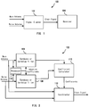
- FIGS. 1 and 2 depict block diagrams of a system for reducing noise using a noise antenna in accordance with one or more embodiments of the present disclosure
- a noise antenna or probe For removing noise from amplitude modulation (AM) broadcast signal, a noise antenna or probe may be used and based on the signals from the noise antenna and inherent constant phase of AM broadcast signal, a signal subtraction technique may be employed to remove the noise.
- this technique fails when there is a noise that includes varying phase signals such as digital radio signals.
- the embodiments described herein uses one or more noise antennas along with processing modules and filters that removes non-correlated signals from an AM broadcast signal.
- FIG. 1 illustrates a block diagram of a system 100 for reducing noise in an AM signal.
- the system 100 includes a coupling to couple to a main antenna and a coupling to connect to one or more noise probes that are placed in a vehicle.
- the location and orientation of the noise probe or probes is decided based on the location of the potential noise sources.
- An AM antenna measure the incoming radio frequency (RF) signal compared to the ground plane.
- RF radio frequency
- the vehicle body provides a stable reference.
- the ground plane is distorted by electrical components such as transformers.
- the noise probe is placed pointing towards earth.
- the system 100 includes a signal cleaner module 102.
- the signal cleaner module 102 may include a plurality of adaptive filters that can be controlled using adaptive coefficients.
- the signal cleaner module 102 may be coupled to a radio receiver 104.
- An adaptive filter is a system with a linear filter that has a transfer function controlled by variable parameters and a means to adjust those parameters according to an optimization algorithm (e.g., least mean square (LMS) algorithm).
- LMS least mean square
- a transfer function is a mathematical representation of outputs of an adaptive filter in relationship with the inputs thereto.
- a signal processor 114 is provided to analyze the AM signal and the noise signal to determine adaptive coefficients and based on the adaptive coefficients, the first filter 106 and the second filter 108 are adjusted.
- the first filter 106 and the second filter 108 may also be low pass filters.
- the processor 114 Based on the measurements energy of spectrum, the processor 114, provides adaptive coefficients to the first filter 106 and the second filter 108 to shift frequency. The coefficients may also be calculated based on energy measurements per spectral component in the AM signal and the noise signal to find the area with the least energy and a bandpass filter may be defined based on such measurements. If a bandpass filter approach is used, a plurality of stop bands may be defined based on energy measurements per spectral component.
- Fourier analysis may be used to decompose the AM signal into a number of discrete frequencies, or a spectrum of frequencies over a continuous range.
- Outputs of the first filter 106 is only part or parts of spectrum with no AM signal but only the frequency of the low energy area of the spectrum. In other words, the AM signal is removed from input AM signal spectrum by the first filter 106.
- Outputs of the first filter 106 and the second filter 108 are inputted to a subtraction coefficient calculator module 110.
- the subtraction coefficient calculator module 110 may use blind source separation (BSS) or least mean square (LMS) algorithms to derive a set of coefficients. Either both BSS and LMS methods may be used or any one of the BSS and LMS methods.
- BSS blind source separation
- LMS least mean square
- the subtraction coefficient calculator module 110 separates the set of mixed signals x(t) through the determination of un-mixing matrix, to recover an approximation of the original signals.
- LMS algorithms may be used in the subtraction coefficient calculator module 110 to mimic a desired filter by finding filter coefficients that relate to producing the least mean square of the error signal (difference between the desired and the actual signal).
- the subtraction coefficient calculator module 110 works starting with a set of coefficients and updates those coefficients iteratively to find coefficients that provides an optimal filter. These coefficients, which may be complex gain and may also include a component to compensate for a phase difference, are provided to a subtractor 112 that subtracts the noise signal from the AM signal based on the input complex number to provide a clean output. These coefficients may also be applied to incoming antenna signals. These coefficients are calculated from signals from filters 106, 108. However, these coefficients are applied on the original signals from the antennas so no information of the antenna signals is lost by the filtering.
- the subtractor 112 may perform spectral subtraction independently on different bands based on the input coefficients from the subtraction coefficient calculator module 110.
- the input coefficients may represent spectral noise estimates which may be calculated through the Fourier transformation process in the coefficient calculator module 110.
- h is the filter response and the adaptive filter is defined by the vector h ⁇ (n) .
- x denotes an input signal.
- M denotes main antenna and N denotes noise antenna.
- the coefficient update, at time n+1 is calculated using EQ. 2.
- h ⁇ n + 1 h ⁇ n + ⁇ x n N e * n
- the normalized least mean square (NLMS) algorithm may be used to normalize to the signal amplitude.
Landscapes
- Engineering & Computer Science (AREA)
- Computer Networks & Wireless Communication (AREA)
- Signal Processing (AREA)
- Physics & Mathematics (AREA)
- Acoustics & Sound (AREA)
- Multimedia (AREA)
- Noise Elimination (AREA)
Abstract
Description
- The use of electronic components in vehicles has been on the rise since. Newer vehicles, specially hybrid or electrical power vehicles use a substantial amount of electronic circuits. These electronic circuits and the vehicle engine emit noise in amplitude modulation (AM) band and this noise causes interference with AM reception that can be typically found in most vehicles. Typically, AM frequency bands are also used for AM reception as well as digital radio broadcast.
- This Summary is provided to introduce a selection of concepts in a simplified form that are further described below in the Detailed Description. This Summary is not intended to identify key features or essential features of the claimed subject matter, nor is it intended to be used to limit the scope of the claimed subject matter.
- In one embodiment, device to cancel noise in broadcast signal is disclosed. The device a first port to connect to a main antenna, a second port to connect to a noise antenna, a processor coupled to the first port and the second port to measure the broadcast signal received at the first port and a noise signal received at the second port to derive a first set of coefficients, a first adaptive filter coupled to the first port and the processor and a second adaptive filter coupled to the second port and the processor. The first adaptive filter and the second adaptive filters are configurable based on the first set of coefficients to remove the high energy parts of a frequency spectrum of signals received at the first port and the second ports respectively. The device also includes a subtraction coefficient calculator module coupled to the first filter and the second filter to derive a second set of coefficients and a subtractor coupled to the first port, the second port and the subtraction coefficient calculator module to subtract the noise signal from the broadcast signal.
- In some embodiments, the first adaptive filter and the second adaptive filter are configured to remove the high energy parts of a frequency spectrum of signals received at the first port and the second ports respectively based on the first set of coefficients. The second set of coefficients are derived from outputs of the first filter and the second filter. The subtractor is configured to apply the second set of coefficients on signals received on the first port and the second port and the subtracting of the noise signal from the broadcast signal is performed based on the second set of coefficients. The subtraction coefficient calculator is configured to calculate a current error and based on the current error, a filter coefficient is calculated.
- So that the manner in which the above recited features of the present invention can be understood in detail, a more particular description of the invention, briefly summarized above, may be had by reference to embodiments, some of which are illustrated in the appended drawings. It is to be noted, however, that the appended drawings illustrate only typical embodiments of this invention and are therefore not to be considered limiting of its scope, for the invention may admit to other equally effective embodiments. Advantages of the subject matter claimed will become apparent to those skilled in the art upon reading this description in conjunction with the accompanying drawings, in which like reference numerals have been used to designate like elements, and in which:
FIGS. 1 and 2 depict block diagrams of a system for reducing noise using a noise antenna in accordance with one or more embodiments of the present disclosure; - Note that figures are not drawn to scale. Intermediate steps between figure transitions have been omitted so as not to obfuscate the disclosure. Those intermediate steps are known to a person skilled in the art.
- Many well-known manufacturing steps, components, and connectors have been omitted or not described in details in the description so as not to obfuscate the present disclosure.
- For removing noise from amplitude modulation (AM) broadcast signal, a noise antenna or probe may be used and based on the signals from the noise antenna and inherent constant phase of AM broadcast signal, a signal subtraction technique may be employed to remove the noise. However, this technique fails when there is a noise that includes varying phase signals such as digital radio signals. The embodiments described herein uses one or more noise antennas along with processing modules and filters that removes non-correlated signals from an AM broadcast signal.
-
Figure 1 illustrates a block diagram of asystem 100 for reducing noise in an AM signal. Thesystem 100 includes a coupling to couple to a main antenna and a coupling to connect to one or more noise probes that are placed in a vehicle. The location and orientation of the noise probe or probes is decided based on the location of the potential noise sources. An AM antenna measure the incoming radio frequency (RF) signal compared to the ground plane. Typically, the vehicle body provides a stable reference. However, in newer vehicles, especially, electrical powered vehicles, the ground plane is distorted by electrical components such as transformers. In some embodiments, the noise probe is placed pointing towards earth. - The
system 100 includes asignal cleaner module 102. Thesignal cleaner module 102 may include a plurality of adaptive filters that can be controlled using adaptive coefficients. Thesignal cleaner module 102 may be coupled to aradio receiver 104. An adaptive filter is a system with a linear filter that has a transfer function controlled by variable parameters and a means to adjust those parameters according to an optimization algorithm (e.g., least mean square (LMS) algorithm). A transfer function is a mathematical representation of outputs of an adaptive filter in relationship with the inputs thereto. -
Figure 2 is a block diagram of thesignal cleaner module 102. In some embodiments, thesignal cleaner module 102 may employ signal correlation technique to identify noise signals that are not correlated to the AM broadcast signal and adjust one or more filters to remove the noise based on correlation and comparison of the AM signal with the signal from the noise probe. Note that the term AM signal is used herein just as an example for easy understanding of the embodiments herein. A person skilled in the art would appreciate that the embodiments described herein may also be used for cleaning up digital broadcast signals. Thesignal cleaner module 102 includes a first bandpass or bandstop filter (the first filter) 106 coupled to the main antenna and a second bandpass or bandstop filter (the second filter) 108 coupled to the noise antenna. In some embodiments, there asignal processor 114 is provided to analyze the AM signal and the noise signal to determine adaptive coefficients and based on the adaptive coefficients, thefirst filter 106 and thesecond filter 108 are adjusted. In some embodiments, thefirst filter 106 and thesecond filter 108 may also be low pass filters. Based on the measurements energy of spectrum, theprocessor 114, provides adaptive coefficients to thefirst filter 106 and thesecond filter 108 to shift frequency. The coefficients may also be calculated based on energy measurements per spectral component in the AM signal and the noise signal to find the area with the least energy and a bandpass filter may be defined based on such measurements. If a bandpass filter approach is used, a plurality of stop bands may be defined based on energy measurements per spectral component. - To measure the area or areas of the least energy, Fourier analysis may be used to decompose the AM signal into a number of discrete frequencies, or a spectrum of frequencies over a continuous range. Outputs of the
first filter 106 is only part or parts of spectrum with no AM signal but only the frequency of the low energy area of the spectrum. In other words, the AM signal is removed from input AM signal spectrum by thefirst filter 106. - Outputs of the
first filter 106 and thesecond filter 108 are inputted to a subtractioncoefficient calculator module 110. The subtractioncoefficient calculator module 110 may use blind source separation (BSS) or least mean square (LMS) algorithms to derive a set of coefficients. Either both BSS and LMS methods may be used or any one of the BSS and LMS methods. - The AM signal received at the subtraction
coefficient calculator module 110 is a mixed signal the includes the low energy regions of the original broadcast signal mixed with the low energy areas of the noise signal, which can be represented as a set of mixed signals x(t) = (x1(t), ..xn(t)T. The subtractioncoefficient calculator module 110 separates the set of mixed signals x(t) through the determination of un-mixing matrix, to recover an approximation of the original signals. LMS algorithms may be used in the subtractioncoefficient calculator module 110 to mimic a desired filter by finding filter coefficients that relate to producing the least mean square of the error signal (difference between the desired and the actual signal). The subtractioncoefficient calculator module 110 works starting with a set of coefficients and updates those coefficients iteratively to find coefficients that provides an optimal filter. These coefficients, which may be complex gain and may also include a component to compensate for a phase difference, are provided to asubtractor 112 that subtracts the noise signal from the AM signal based on the input complex number to provide a clean output. These coefficients may also be applied to incoming antenna signals. These coefficients are calculated from signals fromfilters - The
subtractor 112 may perform spectral subtraction independently on different bands based on the input coefficients from the subtractioncoefficient calculator module 110. The input coefficients may represent spectral noise estimates which may be calculated through the Fourier transformation process in thecoefficient calculator module 110. - The
coefficient calculator module 110 may calculate the coefficients as follows:
First the current error is calculated using EQ. 1.
- Where h is the filter response and the adaptive filter is defined by the vector h^(n) . x denotes an input signal. Subscript M denotes main antenna and N denotes noise antenna. Based on the current error, the coefficient update, at time n+1, is calculated using EQ. 2.

- The above equations are for example only. In these examples, the frequency response of the input circuit is flat, thus only one complex coefficient value suffices.
- In some examples, the normalized least mean square (NLMS) algorithm may be used to normalize to the signal amplitude. In such examples, the application of normalization changes the coefficient formula (at time n+1) to:

- Where H denotes transposition.
- Some or all of these embodiments may be combined, some may be omitted altogether, and additional process steps can be added while still achieving the products described herein. Thus, the subject matter described herein can be embodied in many different variations, and all such variations are contemplated to be within the scope of what is claimed.
- While one or more implementations have been described by way of example and in terms of the specific embodiments, it is to be understood that one or more implementations are not limited to the disclosed embodiments. To the contrary, it is intended to cover various modifications and similar arrangements as would be apparent to those skilled in the art. Therefore, the scope of the appended claims should be accorded the broadest interpretation so as to encompass all such modifications and similar arrangements.
- The use of the terms "a" and "an" and "the" and similar referents in the context of describing the subject matter (particularly in the context of the following claims) are to be construed to cover both the singular and the plural, unless otherwise indicated herein or clearly contradicted by context. Recitation of ranges of values herein are merely intended to serve as a shorthand method of referring individually to each separate value falling within the range, unless otherwise indicated herein, and each separate value is incorporated into the specification as if it were individually recited herein. Furthermore, the foregoing description is for the purpose of illustration only, and not for the purpose of limitation, as the scope of protection sought is defined by the claims as set forth hereinafter together with any equivalents thereof entitled to. The use of any and all examples, or exemplary language (e.g., "such as") provided herein, is intended merely to better illustrate the subject matter and does not pose a limitation on the scope of the subject matter unless otherwise claimed. The use of the term "based on" and other like phrases indicating a condition for bringing about a result, both in the claims and in the written description, is not intended to foreclose any other conditions that bring about that result. No language in the specification should be construed as indicating any non-claimed element as essential to the practice of the invention as claimed.
- Preferred embodiments are described herein, including the best mode known to the inventor for carrying out the claimed subject matter. Of course, variations of those preferred embodiments will become apparent to those of ordinary skill in the art upon reading the foregoing description. The inventor expects skilled artisans to employ such variations as appropriate, and the inventor intends for the claimed subject matter to be practiced otherwise than as specifically described herein. Accordingly, this claimed subject matter includes all modifications and equivalents of the subject matter recited in the claims appended hereto as permitted by applicable law. Moreover, any combination of the above-described elements in all possible variations thereof is encompassed unless otherwise indicated herein or otherwise clearly contradicted by context.
Claims (8)
- A device (102) to cancel noise in a broadcast signal, the device comprising:a first port to connect to a main antenna;a second port to connect to a noise antenna;a processor (114) coupled to the first port and the second port to measure the broadcast signal received at the first port and a noise signal received at the second port to derive a first set of coefficients;a first adaptive filter (106) coupled to the first port and the processor;a second adaptive filter (108) coupled to the second port and the processor, wherein the first adaptive filter and the second adaptive filters are configurable based on the first set of coefficients;a subtraction coefficient calculator module (110) coupled to the first filter and the second filter to derive a second set of coefficients; anda subtractor (112) coupled to the first port, the second port and the subtraction coefficient calculator module to subtract the noise signal from the broadcast signal.
- The device of claim 1, wherein the first adaptive filter and the second adaptive filter are configured to remove the high energy parts of a frequency spectrum of signals received at the first port and the second ports respectively based on the first set of coefficients.
- The device of claim 1 or 2, wherein the second set of coefficients are derived from outputs of the first filter and the second filter.
- The device of any preceding claim, wherein the subtractor is configured to apply the second set of coefficients on signals received on the first port and the second port.
- The device of any of claims 1 to 3, wherein the subtracting of the noise signal from the broadcast signal is performed based on the second set of coefficients.
- The device of any preceding claim, wherein the subtraction coefficient calculator is configured to calculate a current error and based on the current error, a filter coefficient is calculated.
- The device of claim 6, wherein the current error is calculated using equation :

- The device of claim 6 or 7, wherein the first set of coefficients, at time n+1, are calculated based on the current error using the equation:

Applications Claiming Priority (1)
| Application Number | Priority Date | Filing Date | Title |
|---|---|---|---|
| US15/614,286 US9917656B1 (en) | 2017-06-05 | 2017-06-05 | AM noise cancellation in vehicles |
Publications (2)
| Publication Number | Publication Date |
|---|---|
| EP3413471A1 true EP3413471A1 (en) | 2018-12-12 |
| EP3413471B1 EP3413471B1 (en) | 2021-09-15 |
Family
ID=61525709
Family Applications (1)
| Application Number | Title | Priority Date | Filing Date |
|---|---|---|---|
| EP18170791.0A Not-in-force EP3413471B1 (en) | 2017-06-05 | 2018-05-04 | Am noise cancellation in vehicles |
Country Status (2)
| Country | Link |
|---|---|
| US (1) | US9917656B1 (en) |
| EP (1) | EP3413471B1 (en) |
Families Citing this family (3)
| Publication number | Priority date | Publication date | Assignee | Title |
|---|---|---|---|---|
| US10644757B1 (en) * | 2019-01-22 | 2020-05-05 | Nxp B.V. | Near-field communications device |
| JP7505781B2 (en) * | 2019-03-29 | 2024-06-25 | 原田工業株式会社 | Noise Reduction Device |
| US10812119B1 (en) | 2019-06-19 | 2020-10-20 | Nxp B.V. | Systems and methods involving interference cancellation |
Citations (3)
| Publication number | Priority date | Publication date | Assignee | Title |
|---|---|---|---|---|
| US20110235761A1 (en) * | 2010-02-10 | 2011-09-29 | Roy Oren | Method circuit and system for received signal noise reduction or cancellation |
| US20130120057A1 (en) * | 2009-11-30 | 2013-05-16 | Aisin Seiki Kabushiki Kaisha | Device for electromagnetic noise reduction in a hybrid automotive vehicle, assembly and electromagnetic noise reduction process in a hybrid automotive vehicle |
| US9276618B1 (en) * | 2013-05-03 | 2016-03-01 | Marvell International Ltd. | Systems and methods for sidelobe cancellation |
Family Cites Families (2)
| Publication number | Priority date | Publication date | Assignee | Title |
|---|---|---|---|---|
| EP1879377A3 (en) * | 2006-07-13 | 2010-06-16 | Panasonic Corporation | Portable Device |
| JP2009246936A (en) * | 2008-01-31 | 2009-10-22 | Panasonic Corp | Noise canceler, and high-frequency receiver and portable device each using the same |
-
2017
- 2017-06-05 US US15/614,286 patent/US9917656B1/en not_active Expired - Fee Related
-
2018
- 2018-05-04 EP EP18170791.0A patent/EP3413471B1/en not_active Not-in-force
Patent Citations (3)
| Publication number | Priority date | Publication date | Assignee | Title |
|---|---|---|---|---|
| US20130120057A1 (en) * | 2009-11-30 | 2013-05-16 | Aisin Seiki Kabushiki Kaisha | Device for electromagnetic noise reduction in a hybrid automotive vehicle, assembly and electromagnetic noise reduction process in a hybrid automotive vehicle |
| US20110235761A1 (en) * | 2010-02-10 | 2011-09-29 | Roy Oren | Method circuit and system for received signal noise reduction or cancellation |
| US9276618B1 (en) * | 2013-05-03 | 2016-03-01 | Marvell International Ltd. | Systems and methods for sidelobe cancellation |
Also Published As
| Publication number | Publication date |
|---|---|
| EP3413471B1 (en) | 2021-09-15 |
| US9917656B1 (en) | 2018-03-13 |
Similar Documents
| Publication | Publication Date | Title |
|---|---|---|
| US8666347B2 (en) | Methods and devices for reducing radio frequency interference | |
| US20190123940A1 (en) | Systems and methods for adaptively-tuned digital self-interference cancellation | |
| US8265561B2 (en) | Radio communication apparatus and interference removing method | |
| US20140073266A9 (en) | Methods, systems, and non-transitory computer readable media for wideband frequency and bandwidth tunable filtering | |
| US9197360B2 (en) | Systems and methods for reducing a relatively high power, approximately constant envelope interference signal that spectrally overlaps a relatively low power desired signal | |
| EP3413471B1 (en) | Am noise cancellation in vehicles | |
| EP2710740A1 (en) | Dynamic cancellation of passive intermodulation interference | |
| CN111697991B (en) | Method and wireless communication device for providing non-linear self-interference cancellation | |
| US9100081B2 (en) | Radio reception device for vehicle and noise cancellation method | |
| WO2013056270A1 (en) | Methods, systems, and non-transitory computer readable media for wideband frequency and bandwidth tunable filtering | |
| KR101156131B1 (en) | Method and apparatus of interference suppressioin for the digital satellite transponder | |
| EP2946470A1 (en) | Methods, systems and non-transitory computer readable media for wideband frequency and bandwidth tunable filtering | |
| US7917337B2 (en) | Adaptive self-linearization with separation filter | |
| US20080082281A1 (en) | Adaptive self-linearization | |
| Gardner et al. | Two-stage adaptive noise cancellation for intermittent-signal applications (Corresp.) | |
| JP2014200019A (en) | Interference wave elimination apparatus and interference wave elimination method | |
| US20020181699A1 (en) | System for convolutional echo cancellation by iterative autocorrelation | |
| Jang et al. | Mitigation of the third-order passive intermodulation distortion interference on uplink signal | |
| EP3734316B1 (en) | Loran device with interference cancellation and interference canceller device with related methods | |
| EP3440780B1 (en) | Interference supression in a radio transceiver device | |
| EP2933926B1 (en) | Wireless communication device and sensing method | |
| EP2067252B1 (en) | Adaptive self-linearization | |
| JP2017046123A (en) | Frequency reception signal correction method, frequency reception signal correction device, vehicle noise canceling method, and vehicle noise canceling device | |
| EP3890193B1 (en) | Processing amplitude modulation signals with noise estimation | |
| Lebbou et al. | Noise-suppression method for UAV-OFDM systems by introducing CV-VSS-NLMS algorithm and single-antenna architecture |
Legal Events
| Date | Code | Title | Description |
|---|---|---|---|
| PUAI | Public reference made under article 153(3) epc to a published international application that has entered the european phase |
Free format text: ORIGINAL CODE: 0009012 |
|
| STAA | Information on the status of an ep patent application or granted ep patent |
Free format text: STATUS: THE APPLICATION HAS BEEN PUBLISHED |
|
| AK | Designated contracting states |
Kind code of ref document: A1 Designated state(s): AL AT BE BG CH CY CZ DE DK EE ES FI FR GB GR HR HU IE IS IT LI LT LU LV MC MK MT NL NO PL PT RO RS SE SI SK SM TR |
|
| AX | Request for extension of the european patent |
Extension state: BA ME |
|
| STAA | Information on the status of an ep patent application or granted ep patent |
Free format text: STATUS: REQUEST FOR EXAMINATION WAS MADE |
|
| 17P | Request for examination filed |
Effective date: 20190612 |
|
| RBV | Designated contracting states (corrected) |
Designated state(s): AL AT BE BG CH CY CZ DE DK EE ES FI FR GB GR HR HU IE IS IT LI LT LU LV MC MK MT NL NO PL PT RO RS SE SI SK SM TR |
|
| GRAP | Despatch of communication of intention to grant a patent |
Free format text: ORIGINAL CODE: EPIDOSNIGR1 |
|
| STAA | Information on the status of an ep patent application or granted ep patent |
Free format text: STATUS: GRANT OF PATENT IS INTENDED |
|
| INTG | Intention to grant announced |
Effective date: 20210621 |
|
| GRAS | Grant fee paid |
Free format text: ORIGINAL CODE: EPIDOSNIGR3 |
|
| GRAA | (expected) grant |
Free format text: ORIGINAL CODE: 0009210 |
|
| STAA | Information on the status of an ep patent application or granted ep patent |
Free format text: STATUS: THE PATENT HAS BEEN GRANTED |
|
| AK | Designated contracting states |
Kind code of ref document: B1 Designated state(s): AL AT BE BG CH CY CZ DE DK EE ES FI FR GB GR HR HU IE IS IT LI LT LU LV MC MK MT NL NO PL PT RO RS SE SI SK SM TR |
|
| REG | Reference to a national code |
Ref country code: CH Ref legal event code: EP |
|
| REG | Reference to a national code |
Ref country code: DE Ref legal event code: R096 Ref document number: 602018023484 Country of ref document: DE |
|
| REG | Reference to a national code |
Ref country code: IE Ref legal event code: FG4D |
|
| REG | Reference to a national code |
Ref country code: AT Ref legal event code: REF Ref document number: 1431336 Country of ref document: AT Kind code of ref document: T Effective date: 20211015 |
|
| REG | Reference to a national code |
Ref country code: LT Ref legal event code: MG9D |
|
| REG | Reference to a national code |
Ref country code: NL Ref legal event code: MP Effective date: 20210915 |
|
| PG25 | Lapsed in a contracting state [announced via postgrant information from national office to epo] |
Ref country code: FI Free format text: LAPSE BECAUSE OF FAILURE TO SUBMIT A TRANSLATION OF THE DESCRIPTION OR TO PAY THE FEE WITHIN THE PRESCRIBED TIME-LIMIT Effective date: 20210915 Ref country code: HR Free format text: LAPSE BECAUSE OF FAILURE TO SUBMIT A TRANSLATION OF THE DESCRIPTION OR TO PAY THE FEE WITHIN THE PRESCRIBED TIME-LIMIT Effective date: 20210915 Ref country code: SE Free format text: LAPSE BECAUSE OF FAILURE TO SUBMIT A TRANSLATION OF THE DESCRIPTION OR TO PAY THE FEE WITHIN THE PRESCRIBED TIME-LIMIT Effective date: 20210915 Ref country code: RS Free format text: LAPSE BECAUSE OF FAILURE TO SUBMIT A TRANSLATION OF THE DESCRIPTION OR TO PAY THE FEE WITHIN THE PRESCRIBED TIME-LIMIT Effective date: 20210915 Ref country code: NO Free format text: LAPSE BECAUSE OF FAILURE TO SUBMIT A TRANSLATION OF THE DESCRIPTION OR TO PAY THE FEE WITHIN THE PRESCRIBED TIME-LIMIT Effective date: 20211215 Ref country code: BG Free format text: LAPSE BECAUSE OF FAILURE TO SUBMIT A TRANSLATION OF THE DESCRIPTION OR TO PAY THE FEE WITHIN THE PRESCRIBED TIME-LIMIT Effective date: 20211215 Ref country code: LT Free format text: LAPSE BECAUSE OF FAILURE TO SUBMIT A TRANSLATION OF THE DESCRIPTION OR TO PAY THE FEE WITHIN THE PRESCRIBED TIME-LIMIT Effective date: 20210915 |
|
| REG | Reference to a national code |
Ref country code: AT Ref legal event code: MK05 Ref document number: 1431336 Country of ref document: AT Kind code of ref document: T Effective date: 20210915 |
|
| PG25 | Lapsed in a contracting state [announced via postgrant information from national office to epo] |
Ref country code: LV Free format text: LAPSE BECAUSE OF FAILURE TO SUBMIT A TRANSLATION OF THE DESCRIPTION OR TO PAY THE FEE WITHIN THE PRESCRIBED TIME-LIMIT Effective date: 20210915 Ref country code: GR Free format text: LAPSE BECAUSE OF FAILURE TO SUBMIT A TRANSLATION OF THE DESCRIPTION OR TO PAY THE FEE WITHIN THE PRESCRIBED TIME-LIMIT Effective date: 20211216 |
|
| PG25 | Lapsed in a contracting state [announced via postgrant information from national office to epo] |
Ref country code: AT Free format text: LAPSE BECAUSE OF FAILURE TO SUBMIT A TRANSLATION OF THE DESCRIPTION OR TO PAY THE FEE WITHIN THE PRESCRIBED TIME-LIMIT Effective date: 20210915 |
|
| PG25 | Lapsed in a contracting state [announced via postgrant information from national office to epo] |
Ref country code: IS Free format text: LAPSE BECAUSE OF FAILURE TO SUBMIT A TRANSLATION OF THE DESCRIPTION OR TO PAY THE FEE WITHIN THE PRESCRIBED TIME-LIMIT Effective date: 20220115 Ref country code: SM Free format text: LAPSE BECAUSE OF FAILURE TO SUBMIT A TRANSLATION OF THE DESCRIPTION OR TO PAY THE FEE WITHIN THE PRESCRIBED TIME-LIMIT Effective date: 20210915 Ref country code: SK Free format text: LAPSE BECAUSE OF FAILURE TO SUBMIT A TRANSLATION OF THE DESCRIPTION OR TO PAY THE FEE WITHIN THE PRESCRIBED TIME-LIMIT Effective date: 20210915 Ref country code: RO Free format text: LAPSE BECAUSE OF FAILURE TO SUBMIT A TRANSLATION OF THE DESCRIPTION OR TO PAY THE FEE WITHIN THE PRESCRIBED TIME-LIMIT Effective date: 20210915 Ref country code: PT Free format text: LAPSE BECAUSE OF FAILURE TO SUBMIT A TRANSLATION OF THE DESCRIPTION OR TO PAY THE FEE WITHIN THE PRESCRIBED TIME-LIMIT Effective date: 20220117 Ref country code: PL Free format text: LAPSE BECAUSE OF FAILURE TO SUBMIT A TRANSLATION OF THE DESCRIPTION OR TO PAY THE FEE WITHIN THE PRESCRIBED TIME-LIMIT Effective date: 20210915 Ref country code: NL Free format text: LAPSE BECAUSE OF FAILURE TO SUBMIT A TRANSLATION OF THE DESCRIPTION OR TO PAY THE FEE WITHIN THE PRESCRIBED TIME-LIMIT Effective date: 20210915 Ref country code: ES Free format text: LAPSE BECAUSE OF FAILURE TO SUBMIT A TRANSLATION OF THE DESCRIPTION OR TO PAY THE FEE WITHIN THE PRESCRIBED TIME-LIMIT Effective date: 20210915 Ref country code: EE Free format text: LAPSE BECAUSE OF FAILURE TO SUBMIT A TRANSLATION OF THE DESCRIPTION OR TO PAY THE FEE WITHIN THE PRESCRIBED TIME-LIMIT Effective date: 20210915 Ref country code: CZ Free format text: LAPSE BECAUSE OF FAILURE TO SUBMIT A TRANSLATION OF THE DESCRIPTION OR TO PAY THE FEE WITHIN THE PRESCRIBED TIME-LIMIT Effective date: 20210915 Ref country code: AL Free format text: LAPSE BECAUSE OF FAILURE TO SUBMIT A TRANSLATION OF THE DESCRIPTION OR TO PAY THE FEE WITHIN THE PRESCRIBED TIME-LIMIT Effective date: 20210915 |
|
| REG | Reference to a national code |
Ref country code: DE Ref legal event code: R097 Ref document number: 602018023484 Country of ref document: DE |
|
| PLBE | No opposition filed within time limit |
Free format text: ORIGINAL CODE: 0009261 |
|
| STAA | Information on the status of an ep patent application or granted ep patent |
Free format text: STATUS: NO OPPOSITION FILED WITHIN TIME LIMIT |
|
| PG25 | Lapsed in a contracting state [announced via postgrant information from national office to epo] |
Ref country code: DK Free format text: LAPSE BECAUSE OF FAILURE TO SUBMIT A TRANSLATION OF THE DESCRIPTION OR TO PAY THE FEE WITHIN THE PRESCRIBED TIME-LIMIT Effective date: 20210915 |
|
| 26N | No opposition filed |
Effective date: 20220616 |
|
| PG25 | Lapsed in a contracting state [announced via postgrant information from national office to epo] |
Ref country code: SI Free format text: LAPSE BECAUSE OF FAILURE TO SUBMIT A TRANSLATION OF THE DESCRIPTION OR TO PAY THE FEE WITHIN THE PRESCRIBED TIME-LIMIT Effective date: 20210915 |
|
| REG | Reference to a national code |
Ref country code: CH Ref legal event code: PL |
|
| REG | Reference to a national code |
Ref country code: BE Ref legal event code: MM Effective date: 20220531 |
|
| PG25 | Lapsed in a contracting state [announced via postgrant information from national office to epo] |
Ref country code: MC Free format text: LAPSE BECAUSE OF FAILURE TO SUBMIT A TRANSLATION OF THE DESCRIPTION OR TO PAY THE FEE WITHIN THE PRESCRIBED TIME-LIMIT Effective date: 20210915 Ref country code: LU Free format text: LAPSE BECAUSE OF NON-PAYMENT OF DUE FEES Effective date: 20220504 Ref country code: LI Free format text: LAPSE BECAUSE OF NON-PAYMENT OF DUE FEES Effective date: 20220531 Ref country code: IT Free format text: LAPSE BECAUSE OF FAILURE TO SUBMIT A TRANSLATION OF THE DESCRIPTION OR TO PAY THE FEE WITHIN THE PRESCRIBED TIME-LIMIT Effective date: 20210915 Ref country code: CH Free format text: LAPSE BECAUSE OF NON-PAYMENT OF DUE FEES Effective date: 20220531 |
|
| PG25 | Lapsed in a contracting state [announced via postgrant information from national office to epo] |
Ref country code: IE Free format text: LAPSE BECAUSE OF NON-PAYMENT OF DUE FEES Effective date: 20220504 |
|
| PG25 | Lapsed in a contracting state [announced via postgrant information from national office to epo] |
Ref country code: BE Free format text: LAPSE BECAUSE OF NON-PAYMENT OF DUE FEES Effective date: 20220531 |
|
| P01 | Opt-out of the competence of the unified patent court (upc) registered |
Effective date: 20230725 |
|
| PG25 | Lapsed in a contracting state [announced via postgrant information from national office to epo] |
Ref country code: HU Free format text: LAPSE BECAUSE OF FAILURE TO SUBMIT A TRANSLATION OF THE DESCRIPTION OR TO PAY THE FEE WITHIN THE PRESCRIBED TIME-LIMIT; INVALID AB INITIO Effective date: 20180504 |
|
| PG25 | Lapsed in a contracting state [announced via postgrant information from national office to epo] |
Ref country code: MK Free format text: LAPSE BECAUSE OF FAILURE TO SUBMIT A TRANSLATION OF THE DESCRIPTION OR TO PAY THE FEE WITHIN THE PRESCRIBED TIME-LIMIT Effective date: 20210915 Ref country code: CY Free format text: LAPSE BECAUSE OF FAILURE TO SUBMIT A TRANSLATION OF THE DESCRIPTION OR TO PAY THE FEE WITHIN THE PRESCRIBED TIME-LIMIT Effective date: 20210915 |
|
| PGFP | Annual fee paid to national office [announced via postgrant information from national office to epo] |
Ref country code: GB Payment date: 20240419 Year of fee payment: 7 |
|
| PGFP | Annual fee paid to national office [announced via postgrant information from national office to epo] |
Ref country code: DE Payment date: 20240418 Year of fee payment: 7 |
|
| PGFP | Annual fee paid to national office [announced via postgrant information from national office to epo] |
Ref country code: FR Payment date: 20240418 Year of fee payment: 7 |
|
| PG25 | Lapsed in a contracting state [announced via postgrant information from national office to epo] |
Ref country code: MT Free format text: LAPSE BECAUSE OF FAILURE TO SUBMIT A TRANSLATION OF THE DESCRIPTION OR TO PAY THE FEE WITHIN THE PRESCRIBED TIME-LIMIT Effective date: 20210915 |
|
| REG | Reference to a national code |
Ref country code: DE Ref legal event code: R119 Ref document number: 602018023484 Country of ref document: DE |
|
| PG25 | Lapsed in a contracting state [announced via postgrant information from national office to epo] |
Ref country code: TR Free format text: LAPSE BECAUSE OF FAILURE TO SUBMIT A TRANSLATION OF THE DESCRIPTION OR TO PAY THE FEE WITHIN THE PRESCRIBED TIME-LIMIT Effective date: 20210915 |
|
| GBPC | Gb: european patent ceased through non-payment of renewal fee |
Effective date: 20250504 |
|
| PG25 | Lapsed in a contracting state [announced via postgrant information from national office to epo] |
Ref country code: GB Free format text: LAPSE BECAUSE OF NON-PAYMENT OF DUE FEES Effective date: 20250504 |
|
| PG25 | Lapsed in a contracting state [announced via postgrant information from national office to epo] |
Ref country code: DE Free format text: LAPSE BECAUSE OF NON-PAYMENT OF DUE FEES Effective date: 20251202 |
|
| PG25 | Lapsed in a contracting state [announced via postgrant information from national office to epo] |
Ref country code: FR Free format text: LAPSE BECAUSE OF NON-PAYMENT OF DUE FEES Effective date: 20250531 |