EP3413264A1 - Providing a normalized image - Google Patents
Providing a normalized image Download PDFInfo
- Publication number
- EP3413264A1 EP3413264A1 EP17174564.9A EP17174564A EP3413264A1 EP 3413264 A1 EP3413264 A1 EP 3413264A1 EP 17174564 A EP17174564 A EP 17174564A EP 3413264 A1 EP3413264 A1 EP 3413264A1
- Authority
- EP
- European Patent Office
- Prior art keywords
- intensity
- normalized
- pixels
- image
- intensities
- Prior art date
- Legal status (The legal status is an assumption and is not a legal conclusion. Google has not performed a legal analysis and makes no representation as to the accuracy of the status listed.)
- Granted
Links
Images



Classifications
-
- G—PHYSICS
- G06—COMPUTING OR CALCULATING; COUNTING
- G06T—IMAGE DATA PROCESSING OR GENERATION, IN GENERAL
- G06T5/00—Image enhancement or restoration
- G06T5/50—Image enhancement or restoration using two or more images, e.g. averaging or subtraction
-
- A—HUMAN NECESSITIES
- A61—MEDICAL OR VETERINARY SCIENCE; HYGIENE
- A61B—DIAGNOSIS; SURGERY; IDENTIFICATION
- A61B6/00—Apparatus or devices for radiation diagnosis; Apparatus or devices for radiation diagnosis combined with radiation therapy equipment
- A61B6/58—Testing, adjusting or calibrating thereof
- A61B6/582—Calibration
-
- G—PHYSICS
- G06—COMPUTING OR CALCULATING; COUNTING
- G06T—IMAGE DATA PROCESSING OR GENERATION, IN GENERAL
- G06T5/00—Image enhancement or restoration
- G06T5/40—Image enhancement or restoration using histogram techniques
-
- G—PHYSICS
- G06—COMPUTING OR CALCULATING; COUNTING
- G06T—IMAGE DATA PROCESSING OR GENERATION, IN GENERAL
- G06T5/00—Image enhancement or restoration
- G06T5/90—Dynamic range modification of images or parts thereof
- G06T5/92—Dynamic range modification of images or parts thereof based on global image properties
-
- G—PHYSICS
- G16—INFORMATION AND COMMUNICATION TECHNOLOGY [ICT] SPECIALLY ADAPTED FOR SPECIFIC APPLICATION FIELDS
- G16H—HEALTHCARE INFORMATICS, i.e. INFORMATION AND COMMUNICATION TECHNOLOGY [ICT] SPECIALLY ADAPTED FOR THE HANDLING OR PROCESSING OF MEDICAL OR HEALTHCARE DATA
- G16H30/00—ICT specially adapted for the handling or processing of medical images
- G16H30/20—ICT specially adapted for the handling or processing of medical images for handling medical images, e.g. DICOM, HL7 or PACS
-
- G—PHYSICS
- G06—COMPUTING OR CALCULATING; COUNTING
- G06T—IMAGE DATA PROCESSING OR GENERATION, IN GENERAL
- G06T2207/00—Indexing scheme for image analysis or image enhancement
- G06T2207/10—Image acquisition modality
- G06T2207/10116—X-ray image
-
- G—PHYSICS
- G06—COMPUTING OR CALCULATING; COUNTING
- G06T—IMAGE DATA PROCESSING OR GENERATION, IN GENERAL
- G06T2207/00—Indexing scheme for image analysis or image enhancement
- G06T2207/30—Subject of image; Context of image processing
- G06T2207/30004—Biomedical image processing
- G06T2207/30101—Blood vessel; Artery; Vein; Vascular
Definitions
- Imaging of vessels in an examination region e.g. blood vessels in a patient
- X-ray imaging the technical term is "angiography”
- angiography the technical term is "angiography”
- a common solution to this problem is to use subtraction angiography, where two images of the examination region are recorded, wherein the vessel contains no contrast fluid in the first image and contains contrast fluid in the second image, wherein the contrast fluid has high X-ray attenuation.
- Each of the images comprises image intensities, in particular X-ray intensities.
- a difference between the first image and the second image can then be used as a subtraction image, which enhances changes of the image intensities between the two images, and which in an optimal case (without noise and without motion artifacts) would only display the contribution of the contrast fluid.
- subtraction angiography can be used to quantify the fluid flow within the vessel.
- a common technique for subtraction angiography is "digital subtraction angiography" (a short term is "DSA"), wherein the first image and the second image are recorded using a pixelated X-ray detektor, e.g. a flat panel X-ray detector.
- a X-ray detector and an X-ray source can be mounted e.g. on a C-arm X-ray imaging device to allow taking X-ray images from different view angles during an intervention.
- the subtraction image can be calculated pixel-by-pixel.
- Angiography imaging can be used during interventions ("interventional angiography"), e.g. within the roadmap method, wherein a subtracted vessel image and a fluoroscopic live image containing small surgical devices are overlaid, in order to use the subtracted vessel image for navigation.
- interventions e.g. within the roadmap method, wherein a subtracted vessel image and a fluoroscopic live image containing small surgical devices are overlaid, in order to use the subtracted vessel image for navigation.
- the vessels displayed in the subtracted vessel map are exposed to volatile external effects, e.g. the concentration of radiopaque material, the patient's anatomy and the filling phase (which can be arterial or venous), which lead to different image contrasts.
- volatile external effects e.g. the concentration of radiopaque material, the patient's anatomy and the filling phase (which can be arterial or venous), which lead to different image contrasts.
- image contrasts can lead wrong choices in diagnosis or therapy in general, or to navigational errors in using the roadmap method.
- the invention relates in one aspect to a method for providing a normalized image, wherein in particular the method is implemented by one or more computing devices.
- the method comprises the step of receiving a non-normalized image comprising first pixels and non-normalized intensities by an interface, wherein each of the first pixels is characterized by one of the non-normalized intensities.
- the method comprises determining a subtraction histogram with a calculation unit, wherein the subtraction histogram maps a first intensity to the difference between the relative frequency of the first intensity and the relative frequency of a second intensity, wherein the first intensity is one of the non-normalized intensities and the second intensity is one of the non-normalized intensities.
- the method comprises providing (PROV) a normalized image comprising second pixels and normalized intensities based on the non-normalized image and based on the subtraction histogram with the calculation unit, wherein each of the second pixels is characterized by one of the normalized intensities.
- the relative frequency of the first intensity is the relative frequency of the first intensity with respect to the non-normalized intensities.
- the relative frequency of the second intensity is the relative frequency of the second intensity with respect to the non-normalized intensities.
- the inventor has recognized that based on such a histogram normalized intensities can be calculated particularly fast and efficient, while at the same time the influence of motion artifacts can be taken into account.
- the relative deviation between the negative of the first intensity and the second intensity is smaller than 0.5, or in particular smaller than 0.1, or in particular smaller than 0.05, or in particular smaller than 0.01.
- the negative of the first intensity is the first intensity multiplied by (-1).
- the second intensity is the negative of the first intensity.
- the inventor has recognized that this choice of the second intensity leads to a high fineness of the motion artifact correction for the intensities especially in situations of small motions.
- the subtraction histogram maps the first intensity to zero if the first intensity is positive.
- the inventors have recognized that especially in medical subtraction imaging (e.g. in digital subtraction angiography) the relevant intensities are the negative intensities, because they correspond to contrast fluid (where vessels with contrast fluid have a higher X-ray absorption rate than vessels without contrast fluid). So a restriction of the subtraction histogram to negative values is a restriction to the medical relevant part of the histogram.
- each of the second pixels is assigned to one of the first pixels, wherein the normalized intensities pixel-wisely depend on the non-normalized intensities.
- the normalized intensity of one of the second pixels does not depend on the non-normalized intensity of one of the first pixels, if the said second pixel is not assigned to the said first pixels.
- the only one of the non-normalized intensities a normalized intensity of one of the second pixels depends on is the non-normalized intensity of the one of the first pixels the second pixel is assigned to.
- the term "does not depend” does not exclude an indirect dependence, e.g. a dependence on the measured mean or the measured deviation. The inventor has recognized that a pixel-wise normalization is in particular fast and efficient.
- the normalized intensity of one of the second pixels is a linear function of the non-normalized intensity of the one of the first pixels, wherein the said one of the second pixels is assigned to the said one of the first pixels.
- the step of providing is based on a measured mean and a measured deviation, wherein the measured mean is the mean of the non-normalized intensities weighted according to the subtraction histogram, and wherein the measured deviation is the standard deviation of the non-normalized intensities weighted according to the subtraction histogram.
- the measured mean is the mean of the non-normalized intensities weighted according to the subtraction histogram
- the measured deviation is the standard deviation of the non-normalized intensities weighted according to the subtraction histogram.
- the inventor has recognized that the measured mean and the measured deviation within the subtraction histogram are especially suited for characterizing the intensity distribution fast and efficient.
- a reference mean and a reference deviation are received, and wherein the step of providing is furthermore based on the reference mean and the reference deviation.
- the inventor has recognized that the reference mean and the reference deviation can be used together with the measured mean and the measured deviation to bring the distribution of the intensities in the subtraction histogram to a standard form given by the measured mean and the measured deviation fast and efficient.
- each of the second pixels is assigned to one of the first pixels, wherein a normalized intensity of one of the second pixels is calculated as the sum of two numbers, wherein the first number is the product of a first constant with the non-normalized intensity value of the one of the first pixels assigned to the one of the second pixels, wherein the second number is a second constant, wherein the first constant is the ratio of the reference deviation and the measured deviation, and wherein the second constant is the reference mean subtracted by the product of the first constant and the measured mean.
- this linear transformation can be used for mapping the non-normalized intensities to normalized intensities in a fast and efficient way, while at the same time the measured mean and the measured deviation are being transformed to the reference mean and the reference deviation.
- the step of determining the subtraction histogram comprises a first substep of determining an initial histogram with the calculation unit, wherein the initial histogram maps the first intensity to the relative frequency of the first intensities, and a second substep of determining the subtraction histogram based on the initial histogram with the calculation unit.
- the relative frequency of the first intensity is the number of occurrences of the first intensity in the non-normalized intensities divided by the total number of non-normalized intensities.
- the relative frequency of the first intensity is the number of occurrences of an interval of intensities in the non-normalized intensities divided by the total number of non-normalized intensities, wherein the interval of intensities contains the first intensity.
- the invention relates in one aspect to a providing apparatus for providing a normalized image, comprising the following units:
- the providing apparatus can be embodied to execute the method according to the invention and its aspects.
- the providing apparatus is embodied to execute the method its aspects by the interface and the calculation unit being embodied to execute the respective method steps.
- the providing apparatus can be realized as a data processing system or as a part of a data processing system.
- the providing apparatus can, for example, comprise a cloud-computing system, a computer network, a computer, a tablet computer, a smartphone or the like.
- the providing apparatus can comprise hardware and/or software.
- the hardware can be, for example, a processor system, a memory system and combinations thereof.
- the hardware can be configurable by the software and/or be operable by the software.
- the invention relates in one aspect to an X-ray imaging device, comprising a providing apparatus according to an aspect of the invention.
- the X-ray imaging device comprises an X-ray source and an X-ray detector, and is configured for recording X-ray images of an examination volume, in particular X-ray projections.
- the X-ray imaging device can be realized as a C-arm X-ray imaging device.
- the invention relates in one aspect to a computer program product comprising a computer program, the computer program being loadable into a memory unit of a providing apparatus, including program code sections to make the providing apparatus execute the method according to an aspect of the invention when the computer program is executed in said providing apparatus.
- the invention relates in one aspect to a computer-readable medium, on which program code sections of a computer program are saved, said program code sections being loadable into and/or executable in a providing apparatus to make the providing apparatus execute the method according to an aspect of the invention when the program code sections are executed in providing apparatus.
- the realization of the invention by a computer program product and/or a computer-readable medium has the advantage that already existing providing apparatuses can be easily adopted by software updates in order to work as proposed by the invention.
- the computer program product can be, for example, a computer program or comprise another element apart from the computer program.
- This other element can be hardware, for example a memory device, on which the computer program is stored, a hardware key for using the computer program and the like, and/or software, for example a documentation or a software key for using the computer program.
- a non-normalized image and/or a normalized image can in particular be a subtraction image, or a difference between a first and a second image.
- the first image and/or the second image can be X-ray projections of an examination volume.
- a non-normalized image and/or a normalized image can be a digital subtraction angiography image (abbreviated by "DSA-image") which is generated by calculating the difference between a first image of the examination volume with contrast fluid and a second image of the examination volume without contrast fluid.
- DSA-image digital subtraction angiography image
- the time interval between the recordings of the first and the second image has to be chosen small (in particular below ten minutes, in particular below 1 minute, in particular below 10 seconds) and/or the examination volume must not be moved between the recordings of the first and the second image.
- a first intensity and/or a second intensity can take positive and negative values, and the value zero.
- the non-normalized and/or the normalized image are a subtraction image, in particular a difference between a first and a second image
- an first intensity and/or a second intensity of the non-normalized image and/or the normalized image can be defined as the difference between an intensity of the first image and an intensity of the second image.
- the first intensity and/or a second intensity of the non-normalized image and/or the normalized image can be defined as the difference between an intensity of a pixel of the first image and an intensity of a corresponding pixel of the second image.
- a pixel of the first pixels and/or the second pixels can refer to an elementary two-dimensional building block of a two-dimensional image, especially of a spatial two-dimensional image.
- a pixel can also refer to a higher-dimensional building block of a higher-dimensional image, especially a spatial higher-dimensional image.
- a pixel can refer to a voxel, and/or a pixel can contain additional time information, wherein the time information is inherited by the image the pixel is contained in.
- Each pixel of the first pixels is characterized by a non-normalized intensity
- each pixel of the second pixels is characterized by a normalized intensity.
- the number of the second pixels can be equal to the number of first pixels. Additionally the arrangement of the second pixels can be equal to the arrangement of the first pixels, so that there is a one-to-one correspondence between the first pixels and the second pixels. In a one-to-one correspondence each of the second pixels can be assigned to one of the first pixels.
- the first pixels and the second pixels can both be arranged in a rectangle characterized by the same edge lengths, alternatively the first pixels and the second pixels can both be arranged in a cubus characterized by the same edge lengths.
- Fig. 1 shows a flow chart of a first embodiment of the method for providing a normalized image.
- the first step of this embodiment is receiving REC a non-normalized image 430, 530 comprising first pixels and non-normalized intensities 601 by an interface 301, wherein each of the first pixels is characterized by one of the non-normalized intensities 601.
- the non-normalized image 430, 530 in this embodiment is the difference between a first image 410, 510 and a second image 420, 520, wherein the first image 410, 510 and the second image 420, 520 comprise the same number of pixels, and wherein the arrangement of the pixels of the first image 410, 510 is equals the arrangement of the pixels of the second image 420, 520, so that there is a one-to-one correspondence between pixels of the first image 410, 510 and the pixels of the second image 420, 520.
- the non-normalized intensities 601 are relative intensities. Each of the non-normalized intensities 601 is the difference between the intensity of one of the pixels of the first image 410, 510 and the intensity of the corresponding one of the pixels of the second image 420, 520. As a consequence, non-normalized intensities 601 can be negative, zero or positive.
- This embodiment can be used for the non-normalized image 430, 530 being a digital subtraction angiography image.
- the first image and the second image are images of the same region of interest, wherein the region of interest contains a vessel, and wherein during the recording of the second image there is more contrast fluid in the vessel that during the recording of the first image.
- the next step of this embodiment is determining DET a subtraction histogram 800 with the calculation unit 302, wherein the subtraction histogram 800 maps a first intensity to the difference between the relative frequency 602 of the first intensity and the relative frequency 602 of a second intensity, wherein the first intensity is one of the non-normalized intensities 601 and the second intensity is one of the non-normalized intensities 601.
- the relative frequency 602 of a first intensity and a second intensity is a measure for the relative frequency 602 of the first intensity and the second intensity within the non-normalize intensities.
- the relative frequency 602 of a first intensity and a second intensity is the relative frequency 602 of the first intensity and the second intensity within the non-normalized intensities 601, which is the number of occurrences of the first intensity and the second intensity in the non-normalized intensities 601 divided by the total number of non-normalized intensities 601.
- each of the relative frequency 602 of a first intensity and a second intensity can also be the relative frequency 602 of a subset of intensities containing the first intensity and the second intensity, or in particular of an interval of non-normalized intensities 601 containing the first intensity and the second intensity.
- a technical term for this definition is binning.
- the boundaries of the intervals can be defined independently of the first frequency (e.g. by the intervals [k ⁇ I, (k+1) ⁇ ⁇ I[, where k is an integer number and ⁇ I is the width of the interval).
- the boundaries can also be defined relative to the first intensity (e.g. by [x - ⁇ I/2, x - ⁇ I/2], where x is the first intensity and ⁇ I is the width of the interval.
- each of the relative frequencies of a first intensity and a second intensity can also be calculated using a kernel density estimation.
- H i 1 nh ⁇ x , y K i ⁇ I NN x y h
- n is the number of non-normalized intensities 601, h > 0 is a smoothing parameter
- K is the kernel function.
- a kernel function one can use for example a Gaussian kernel or a Cauchy kernel.
- the constant can be chosen as the mean of the non-normalized intensities 601, or alternatively as the mean of the non-normalized intensities 601 weighted by their relative frequency 602.
- the last step of this embodiment is providing (PROV) a normalized image comprising second pixels and normalized intensities 801 based on the non-normalized image 430, 530 and based on the subtraction histogram 800 with the calculation unit 302, wherein each of the second pixels is characterized by one of the normalized intensities 801.
- the constants m and t only depend on the measured mean ⁇ m and the measured deviation ⁇ m of the non-normalized intensities 601 weighted according to the subtraction histogram 800, and a reference mean 802 ⁇ r and a reference ⁇ r deviation.
- Fig. 2 shows another embodiment of the method for providing a normalized image.
- the steps of receiving REC and providing PROV are analogous to the embodiment described in Fig. 1 .
- the step of determining DET is divided in a first substep of determining DET-1 and a second substep of determining DET-2.
- a plain histogram 600 is calculated based on the non-normalized intensities 601 of the non-normalized image 430, 530.
- the plain histogram 600 maps the first intensity to the relative frequency 602 of the first intensity in the non-normalized intensities 601.
- the relative frequency 602 is a measure for the relative frequency 602 of the first intensity within the non-normalized intensities 601, which is described in detail in the description of Fig. 1 .
- the subtraction histogram 800 is calculated based on the plain histogram 600 with the calculation unit 302.
- the constant can be chosen as the mean of the non-normalized intensities 601, or alternatively as the mean of the non-normalized intensities 601 weighted by their relative frequency 602.
- Fig. 3 displays a providing apparatus 300 for providing a normalized image.
- the displayed providing apparatus 300 is embodied to execute a method according to the invention.
- the providing apparatus 300 comprises an interface 301, a calculation unit 302, a memory unit 303 and a input and/or output unit 304.
- the providing apparatus can be a computer, a microcontroller, or an integrated circuit.
- the providing apparatus 300 can be a real or a virtual group of computers (the technical term for a real group of computers is "cluster", the technical term for a virtual group of computers is "cloud").
- An interface 301 can be embodies as a hardware interface or as a software interface (e.g. PCI-Bus, USB or Firewire).
- a calculation unit 302 can comprise hardware elements and software elements, for example a microprocessor or a field programmable gate array.
- a memory unit 303 can be embodied as non-permanent main memory (e.g. random access memory) or as permanent mass storage (e.g. hard disk, USB stick, SD card, solid state disk).
- a input and/or output unit 404 comprises at least one input unit (e.g. mouse, keyboard) and/or at least one output unit (e.g. display, printer).
- Fig. 4 shows a first image 410, a second image 420 and a subtraction image 430, wherein the subtraction image 430 is calculated as the difference between the first image 410 and the second image 420.
- Each of the images 410, 420, 430 comprises a vessel 411, 421, 431 and other image regions 412, 413, 422, 423, 432, 433.
- the field of view of the first image 410 equals the field of view of the second image 420, and there was no motion of the field of view between the recording time of the first image 410 and the second image 420, so there is no motion artifact in the subtraction image 430.
- the vessel 411 in the first image 410 is filled with blood
- the vessel 421 in the second image 420 is additionally filled with a contrast liquid, so that the X-ray attenuation is higher than in the first image 410, so that the X-ray intensity is lower in the second image 420 than in the first image 410.
- the vessel is displayed with a negative intensity.
- the X-ray attenuations of the other regions 412, 413 in the first image 410 equals the X-ray attenuation of the other regions 422, 423 in the second image 420, so that the X-ray intensities are equal in the first image 410 and in the second image 420.
- the intensity of the other regions 432, 433 in the subtraction image 430 is zero up to noise.
- Fig. 5 shows a first image 510, a second image 520 and a subtraction image 530, wherein the subtraction image 530 is calculated as the difference between the first image 510 and the second image 520.
- the first image 510 and the second image 520 comprise a vessel 511, 521 and other image regions 512, 513, 522, 523.
- the vessel 511 in the first image 510 is filled with blood
- the vessel 521 in the second image 520 is additionally filled with a contrast liquid, so that the X-ray attenuation is higher than in the first image 510, so that the X-ray intensity is lower in the second image 520 than in the first image 510.
- the X-ray attenuations of the other regions 512, 513 in the first image 510 equals the X-ray attenuation of the other regions 522, 523 in the second image 520, so that the X-ray intensities are equal in the first image 510 and in the second image 520.
- the field of view of the second image 520 is shifted to the left.
- This shift can be caused by a motion within the field of view (e.g. by the breathing of a patient), or by a motion of the X-ray imaging system.
- a motion within the field of view e.g. by the breathing of a patient
- a motion of the X-ray imaging system e.g. by the breathing of a patient
- the vessel 531.1 in the position of the first image 510 and the vessel 531.2 in the position of the second image 520 are displayed.
- motion artifacts can be found if considering the other regions 512, 513, 522, 523.
- the position of the other regions 532.1, 533.2 in the first image 510 and the position of the other regions 532.2, 533.2 in the second image 520 is displayed. Since the first image 510 and the second image 520 contribute to the subtraction image 530 with different signs, in the subtraction image 530 one finds as a motion artifact areas with positive intensity and areas with negative intensity, wherein the corresponding areas have the same size.
- positive intensity is displayed by a hatching from the upper left to the lower right
- negative intensity is displayed by a hatching from the upper right to the lower left.
- non-normalized intensities 601 and the normalized intensities 801 are displayed as an axis corresponding to an independent variable.
- the terms "normalized intensities" 801 and "non-normalized intensities" 601 may refer to multisets, i.e. sets where elements can more than once. For example, if in the non-normalized image there are several pixels characterized by the same non-normalized intensity, this said non-normalized intensity is contained in the non-normalized intensities 601 more than once.
- the non-normalized intensities 601 and the normalized intensities 801 can refer to a tuple without ordering.
- normalized intensities and non-normalized intensities have to be understood as axes corresponding to an independent variable if the notion with an integral is used (e.g. in the calculation of the measured mean and the measured deviation). If otherwise the notion with a sum is used, "normalized intensities” and “non-normalized intensities” have to be understood as multisets. In particular, “normalized intensities” and “non-normalized intensities” have to be understood as multisets if the relation between the normalized intensities of the second pixels and the non-normalized intensities of the first pixels is described.
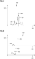
- Fig. 6 shows examples of plain histograms 600 of intensities for subtraction images 430, 530 without motion artifacts, but with contrast fluid (left), for subtraction images 430, 530 with motion artifacts, but without contrast fluid (middle), and for subtraction images 430, 530 with motion artifacts and contrast fluid (right).
- the plain histogram 600 is a map from non-normalized intensities 601 to their relative frequency 602 in the subtraction image 430, 530.
- the dashed line indicates the origin 603 of the non-normalized intensities 601. In other words, the origin 603 is the non-normalized intensity with value zero.
- the plain histogram 600 comprises a noise peak 610, which is due to image noise in the first image 410, 510 and/or the second image 420, 520, and which is symmetric with respect to the origin 603 in a good approximation.
- the plain histogram 600 can furthermore comprise a contrast peak 611, which is due to vessels being filled with contrast fluid in the second image 420, 520, but not in the first image 410, 510, as explained within the description of Fig. 4 and Fig. 5 .
- the plain histogram 600 can furthermore comprise motion artifact peaks 612.1, 612.2.
- the motion artifact peaks 612.1 and 612.2 are symmetric with respect to the origin 603 up to boundary effects, as explained in the description of Fig. 5 . If motion artifacts and contrast fluid is involved, the motion artifact peak 612.1 and the contrast peak 611 are merge to a total peak 613.
- Fig. 7 displays the method of calculating a subtraction histogram 800 from a plain histogram 600
- the resulting subtraction histogram 800 is displayed in Fig. 8 .
- the plain histogram 600 is divided in a positive part 701, which is the plain histogram 600 restricted to positive non-normalized intensities 601, and a negative part 702, which is restricted to negative non-normalized intensities 601.
- the positive part 701 can be mirrored with respect to the origin 603, resulting in a mirrored positive part 703.
- the resulting subtraction histogram 800 can then be interpreted as the difference of the negative part 702 and the mirrored positive part 703, restricted to negative non-normalized intensities 601.
- the subtraction histogram 800 is displayed with the non-normalized intensities 601 and with the normalized intensities 801 as independent variable.
- the curve 810 is the difference between the mirrored positive part 703 and the negative part 802 with respect to the non-normalized intensities 601;
- the curve 811 is the difference between the mirrored positive part 703 and the negative part 802 with respect to the normalized intensities 801. Both curves 810, 811 can be interpreted as histograms.
- the normalized intensities 801 are calculated from the non-normalized intensities 601 by applying a linear transformation as described above, so that the mean of the histogram 811 corresponds to a reference mean 802, and so that the standard deviation of the histogram 811 corresponds to a reference deviation 803.
- Fig. 9 displays an X-ray imaging device 900 which is connected to a providing apparatus 300.
- the X-ray imaging device 900 is a C-arm X-ray imaging device.
- the X-ray imaging device 900 comprises a X-ray source 901 for generating X-rays and a X-ray detector 902 for receiving X-rays.
- the X-ray source 901 and the X-ray detector 902 are embodied at opposite sides of a C-arm 903.
- the C-arm 903 of the X-ray imaging device 900 is attached to a stand 904.
- the stand 904 comprises means (e.g. motors) for changing the position of the C-arm 903, in particular, the C-arm can be rotated around two different axis.
- the X-ray imaging device 900 comprises a control and analyzing unit 905 as well as a patient positioning unit 906, which can be used for positioning a patient 907.
- control and analyzing unit 905 uses the control and analyzing unit 905 to adjust the position of the C-arm 903, and the C-arm 803 can be rotated around the patient 907. Furthermore, using the control and analyzing unit 905 two-dimensional X-ray projections of the patient can be recorded. In general it is possible to record higher-dimensional data by combining two or more two-dimensional X-ray projections.
- the control and analyzing unit 905 can comprise the providing apparatus 300.
- the X-ray source 901 is an X-ray tube.
- the X-ray source 901 can also be a linear accelerator, an X-ray laser, an synchrotron or a cyclotron.
- the X-ray detector 902 is a flat panel X-ray detector.
- the X-ray detector 902 can be a semiconductor detector, an X-ray film, a photostimulable phosphor plate, or an X-ray image intensifier.
Landscapes
- Engineering & Computer Science (AREA)
- Health & Medical Sciences (AREA)
- Physics & Mathematics (AREA)
- General Physics & Mathematics (AREA)
- Theoretical Computer Science (AREA)
- Medical Informatics (AREA)
- Life Sciences & Earth Sciences (AREA)
- General Health & Medical Sciences (AREA)
- Radiology & Medical Imaging (AREA)
- Nuclear Medicine, Radiotherapy & Molecular Imaging (AREA)
- Public Health (AREA)
- Surgery (AREA)
- Biophysics (AREA)
- Biomedical Technology (AREA)
- Heart & Thoracic Surgery (AREA)
- Molecular Biology (AREA)
- High Energy & Nuclear Physics (AREA)
- Animal Behavior & Ethology (AREA)
- Pathology (AREA)
- Optics & Photonics (AREA)
- Veterinary Medicine (AREA)
- Epidemiology (AREA)
- Primary Health Care (AREA)
- Apparatus For Radiation Diagnosis (AREA)
- Image Processing (AREA)
Abstract
Description
- Imaging of vessels in an examination region, e.g. blood vessels in a patient, using X-ray imaging (the technical term is "angiography") is difficult due to the low X-ray attenuation of the vessels and/or of the contents of the vessels.
- A common solution to this problem is to use subtraction angiography, where two images of the examination region are recorded, wherein the vessel contains no contrast fluid in the first image and contains contrast fluid in the second image, wherein the contrast fluid has high X-ray attenuation. Each of the images comprises image intensities, in particular X-ray intensities. A difference between the first image and the second image can then be used as a subtraction image, which enhances changes of the image intensities between the two images, and which in an optimal case (without noise and without motion artifacts) would only display the contribution of the contrast fluid. Additionally in this setup, subtraction angiography can be used to quantify the fluid flow within the vessel.
- A common technique for subtraction angiography is "digital subtraction angiography" (a short term is "DSA"), wherein the first image and the second image are recorded using a pixelated X-ray detektor, e.g. a flat panel X-ray detector. Such a X-ray detector and an X-ray source can be mounted e.g. on a C-arm X-ray imaging device to allow taking X-ray images from different view angles during an intervention. Within DSA the subtraction image can be calculated pixel-by-pixel.
- Angiography imaging can be used during interventions ("interventional angiography"), e.g. within the roadmap method, wherein a subtracted vessel image and a fluoroscopic live image containing small surgical devices are overlaid, in order to use the subtracted vessel image for navigation.
- The vessels displayed in the subtracted vessel map are exposed to volatile external effects, e.g. the concentration of radiopaque material, the patient's anatomy and the filling phase (which can be arterial or venous), which lead to different image contrasts. Such variations of the image contrast can lead wrong choices in diagnosis or therapy in general, or to navigational errors in using the roadmap method.
- It is known to use a statistical analysis of the subtracted image in order to reduce the variation in the image contrast. These analysis are limited especially if motion artifacts between the first and the second image are present.
- It is the object of the present invention to provide an image with reduced variations of the image contrast, even if motion artifacts are present.
- This object is solved by a method according to
claim 1, a providing apparatus according to claim 12, an X-ray imaging apparatus according to claim 14, a computer program product according to claim 15 and a computer-readable storage medium according to claim 16. - In the following the solution according to the invention is described with respect to the claimed apparatus as well as with respect to the claimed method. Features, advantages or alternative embodiments herein can be assigned to the other claimed objects and vice versa. In other words, claims for the apparatus can be improved with features described or claimed in the context of the method. In this case, the functional features of the method are embodied by objective units of the apparatus.
- The invention relates in one aspect to a method for providing a normalized image, wherein in particular the method is implemented by one or more computing devices. The method comprises the step of receiving a non-normalized image comprising first pixels and non-normalized intensities by an interface, wherein each of the first pixels is characterized by one of the non-normalized intensities. Furthermore, the method comprises determining a subtraction histogram with a calculation unit, wherein the subtraction histogram maps a first intensity to the difference between the relative frequency of the first intensity and the relative frequency of a second intensity, wherein the first intensity is one of the non-normalized intensities and the second intensity is one of the non-normalized intensities. Furthermore, the method comprises providing (PROV) a normalized image comprising second pixels and normalized intensities based on the non-normalized image and based on the subtraction histogram with the calculation unit, wherein each of the second pixels is characterized by one of the normalized intensities.
- The relative frequency of the first intensity is the relative frequency of the first intensity with respect to the non-normalized intensities. The relative frequency of the second intensity is the relative frequency of the second intensity with respect to the non-normalized intensities.
- The inventor has recognized that based on such a histogram normalized intensities can be calculated particularly fast and efficient, while at the same time the influence of motion artifacts can be taken into account.
- According to a further aspect of the invention, the relative deviation between the negative of the first intensity and the second intensity is smaller than 0.5, or in particular smaller than 0.1, or in particular smaller than 0.05, or in particular smaller than 0.01. The negative of the first intensity is the first intensity multiplied by (-1). The relative deviation δI between the negative -I1 of the first intensity I1 and the second intensity I2 is defined as δI = |(- I1 - I2)/I1|. The inventor has recognized that this choice of the second intensity leads to a high fineness of the motion artifact correction for the normalized intensities.
- According to a further aspect of the invention, the second intensity is the negative of the first intensity. The inventor has recognized that this choice of the second intensity leads to a high fineness of the motion artifact correction for the intensities especially in situations of small motions.
- According to a further aspect of the invention, the subtraction histogram maps the first intensity to zero if the first intensity is positive. The inventors have recognized that especially in medical subtraction imaging (e.g. in digital subtraction angiography) the relevant intensities are the negative intensities, because they correspond to contrast fluid (where vessels with contrast fluid have a higher X-ray absorption rate than vessels without contrast fluid). So a restriction of the subtraction histogram to negative values is a restriction to the medical relevant part of the histogram.
- According to a further aspect of the invention each of the second pixels is assigned to one of the first pixels, wherein the normalized intensities pixel-wisely depend on the non-normalized intensities. In other words, the normalized intensity of one of the second pixels does not depend on the non-normalized intensity of one of the first pixels, if the said second pixel is not assigned to the said first pixels. In other words, the only one of the non-normalized intensities a normalized intensity of one of the second pixels depends on is the non-normalized intensity of the one of the first pixels the second pixel is assigned to. Herein the term "does not depend" does not exclude an indirect dependence, e.g. a dependence on the measured mean or the measured deviation. The inventor has recognized that a pixel-wise normalization is in particular fast and efficient.
- According to a further aspect of the invention the normalized intensity of one of the second pixels is a linear function of the non-normalized intensity of the one of the first pixels, wherein the said one of the second pixels is assigned to the said one of the first pixels. The inventor has recognized that the usage of a linear function leads to a fast and efficient computation of the normalized intensities.
- According to a further aspect of the invention, the step of providing is based on a measured mean and a measured deviation, wherein the measured mean is the mean of the non-normalized intensities weighted according to the subtraction histogram, and wherein the measured deviation is the standard deviation of the non-normalized intensities weighted according to the subtraction histogram. In other words, the measured mean is the mean of the non-normalized intensities weighted according to the subtraction histogram, and the measured deviation is the standard deviation of the non-normalized intensities weighted according to the subtraction histogram. The inventor has recognized that the measured mean and the measured deviation within the subtraction histogram are especially suited for characterizing the intensity distribution fast and efficient.
- The measured mean µm is in particular defined as


- According to a further aspect of the invention, within the step of receiving furthermore a reference mean and a reference deviation are received, and wherein the step of providing is furthermore based on the reference mean and the reference deviation. The inventor has recognized that the reference mean and the reference deviation can be used together with the measured mean and the measured deviation to bring the distribution of the intensities in the subtraction histogram to a standard form given by the measured mean and the measured deviation fast and efficient.
- According to a further aspect of the invention each of the second pixels is assigned to one of the first pixels, wherein a normalized intensity of one of the second pixels is calculated as the sum of two numbers, wherein the first number is the product of a first constant with the non-normalized intensity value of the one of the first pixels assigned to the one of the second pixels, wherein the second number is a second constant, wherein the first constant is the ratio of the reference deviation and the measured deviation, and wherein the second constant is the reference mean subtracted by the product of the first constant and the measured mean. The inventor has recognized that this linear transformation can be used for mapping the non-normalized intensities to normalized intensities in a fast and efficient way, while at the same time the measured mean and the measured deviation are being transformed to the reference mean and the reference deviation.
- According to a further aspect of the invention the step of determining the subtraction histogram comprises a first substep of determining an initial histogram with the calculation unit, wherein the initial histogram maps the first intensity to the relative frequency of the first intensities, and a second substep of determining the subtraction histogram based on the initial histogram with the calculation unit. The inventor has recognized that by determining the initial histogram before the subtraction histogram properties of the initial histogram can be used for the determining of the subtraction histogram or for the providing of the normalized image more precisely.
- According to a possible further aspect of the invention the relative frequency of the first intensity is the number of occurrences of the first intensity in the non-normalized intensities divided by the total number of non-normalized intensities. The inventor has recognized that using the number of occurrences of a single intensity as the relative frequency leads to a more exact calculation of a normalized image.
- According to a possible further aspect of the invention the relative frequency of the first intensity is the number of occurrences of an interval of intensities in the non-normalized intensities divided by the total number of non-normalized intensities, wherein the interval of intensities contains the first intensity. The inventor has recognized that using the number of occurrences of a subset of intensities leads to a fast calculation of the normalized image.
- The invention relates in one aspect to a providing apparatus for providing a normalized image, comprising the following units:
- interface, configured for receiving a non-normalized image comprising first pixels and non-normalized intensities by an interface, wherein each of the first pixels is characterized by one of the non-normalized intensities,
- calculation unit, configured for determining a subtraction histogram, wherein the subtraction histogram maps a first intensity to the difference between the relative frequency of the first intensity and the relative frequency of a second intensity, wherein the first intensity is one of the non-normalized intensities and the second intensity is one of the non-normalized intensities,
- In particular the providing apparatus can be embodied to execute the method according to the invention and its aspects. The providing apparatus is embodied to execute the method its aspects by the interface and the calculation unit being embodied to execute the respective method steps.
- The providing apparatus can be realized as a data processing system or as a part of a data processing system. The providing apparatus can, for example, comprise a cloud-computing system, a computer network, a computer, a tablet computer, a smartphone or the like. The providing apparatus can comprise hardware and/or software. The hardware can be, for example, a processor system, a memory system and combinations thereof. The hardware can be configurable by the software and/or be operable by the software.
- The invention relates in one aspect to an X-ray imaging device, comprising a providing apparatus according to an aspect of the invention.
- The X-ray imaging device comprises an X-ray source and an X-ray detector, and is configured for recording X-ray images of an examination volume, in particular X-ray projections. The X-ray imaging device can be realized as a C-arm X-ray imaging device.
- The invention relates in one aspect to a computer program product comprising a computer program, the computer program being loadable into a memory unit of a providing apparatus, including program code sections to make the providing apparatus execute the method according to an aspect of the invention when the computer program is executed in said providing apparatus.
- The invention relates in one aspect to a computer-readable medium, on which program code sections of a computer program are saved, said program code sections being loadable into and/or executable in a providing apparatus to make the providing apparatus execute the method according to an aspect of the invention when the program code sections are executed in providing apparatus.
- The realization of the invention by a computer program product and/or a computer-readable medium has the advantage that already existing providing apparatuses can be easily adopted by software updates in order to work as proposed by the invention.
- The computer program product can be, for example, a computer program or comprise another element apart from the computer program. This other element can be hardware, for example a memory device, on which the computer program is stored, a hardware key for using the computer program and the like, and/or software, for example a documentation or a software key for using the computer program.
- A non-normalized image and/or a normalized image can in particular be a subtraction image, or a difference between a first and a second image. The first image and/or the second image can be X-ray projections of an examination volume. In particular a non-normalized image and/or a normalized image can be a digital subtraction angiography image (abbreviated by "DSA-image") which is generated by calculating the difference between a first image of the examination volume with contrast fluid and a second image of the examination volume without contrast fluid. In order to have only small motion artifacts, the time interval between the recordings of the first and the second image has to be chosen small (in particular below ten minutes, in particular below 1 minute, in particular below 10 seconds) and/or the examination volume must not be moved between the recordings of the first and the second image.
- A first intensity and/or a second intensity can take positive and negative values, and the value zero. If the non-normalized and/or the normalized image are a subtraction image, in particular a difference between a first and a second image, an first intensity and/or a second intensity of the non-normalized image and/or the normalized image can be defined as the difference between an intensity of the first image and an intensity of the second image. In particular, the first intensity and/or a second intensity of the non-normalized image and/or the normalized image can be defined as the difference between an intensity of a pixel of the first image and an intensity of a corresponding pixel of the second image.
- A pixel of the first pixels and/or the second pixels can refer to an elementary two-dimensional building block of a two-dimensional image, especially of a spatial two-dimensional image. A pixel can also refer to a higher-dimensional building block of a higher-dimensional image, especially a spatial higher-dimensional image. In particular, a pixel can refer to a voxel, and/or a pixel can contain additional time information, wherein the time information is inherited by the image the pixel is contained in. Each pixel of the first pixels is characterized by a non-normalized intensity, and each pixel of the second pixels is characterized by a normalized intensity.
- The number of the second pixels can be equal to the number of first pixels. Additionally the arrangement of the second pixels can be equal to the arrangement of the first pixels, so that there is a one-to-one correspondence between the first pixels and the second pixels. In a one-to-one correspondence each of the second pixels can be assigned to one of the first pixels. In particular, the first pixels and the second pixels can both be arranged in a rectangle characterized by the same edge lengths, alternatively the first pixels and the second pixels can both be arranged in a cubus characterized by the same edge lengths.
- Fig. 1
- shows a flow chart of a first embodiment of the method for providing a normalized image,
- Fig. 2
- shows a flow chart of a second embodiment of the method for providing a normalized image,
- Fig. 3
- shows a providing apparatus,
- Fig. 4
- shows a first image, a second image and a subtraction of the first and the second image, each comprising a vessel, without motion artifacts,
- Fig. 5
- shows a first image, a second image and a subtraction of the first and the second image, each comprising a vessel, with motion artifact,
- Fig. 6
- shows plain histograms of subtraction images,
- Fig. 7
- shows a calculation method for the subtraction histogram,
- Fig. 8
- shows a subtraction histogram, and
- Fig. 9
- shows a C-arm X-ray imaging unit.
-
Fig. 1 shows a flow chart of a first embodiment of the method for providing a normalized image. The first step of this embodiment is receiving REC anon-normalized image non-normalized intensities 601 by aninterface 301, wherein each of the first pixels is characterized by one of thenon-normalized intensities 601. - The
non-normalized image first image second image first image second image first image second image first image second image - In this embodiment, the
non-normalized intensities 601 are relative intensities. Each of thenon-normalized intensities 601 is the difference between the intensity of one of the pixels of thefirst image second image non-normalized intensities 601 can be negative, zero or positive. - This embodiment can be used for the
non-normalized image non-normalized image 
- The next step of this embodiment is determining DET a
subtraction histogram 800 with thecalculation unit 302, wherein thesubtraction histogram 800 maps a first intensity to the difference between therelative frequency 602 of the first intensity and therelative frequency 602 of a second intensity, wherein the first intensity is one of thenon-normalized intensities 601 and the second intensity is one of thenon-normalized intensities 601. Here therelative frequency 602 of a first intensity and a second intensity is a measure for therelative frequency 602 of the first intensity and the second intensity within the non-normalize intensities. - In this embodiment, the
relative frequency 602 of a first intensity and a second intensity is therelative frequency 602 of the first intensity and the second intensity within thenon-normalized intensities 601, which is the number of occurrences of the first intensity and the second intensity in thenon-normalized intensities 601 divided by the total number ofnon-normalized intensities 601. - Alternatively, each of the
relative frequency 602 of a first intensity and a second intensity can also be therelative frequency 602 of a subset of intensities containing the first intensity and the second intensity, or in particular of an interval ofnon-normalized intensities 601 containing the first intensity and the second intensity. A technical term for this definition is binning. The boundaries of the intervals can be defined independently of the first frequency (e.g. by the intervals [k·ΔI, (k+1) · ΔI[, where k is an integer number and ΔI is the width of the interval). Alternatively, the boundaries can also be defined relative to the first intensity (e.g. by [x - ΔI/2, x - ΔI/2], where x is the first intensity and ΔI is the width of the interval. - Alternatively, each of the relative frequencies of a first intensity and a second intensity can also be calculated using a kernel density estimation.

non-normalized intensities 601, h > 0 is a smoothing parameter, and K is the kernel function. As a kernel function, one can use for example a Gaussian kernel or a Cauchy kernel. A Gaussian kernel or a Cauchy kernel are given by the formulas

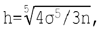
non-normalized intensities 601. - In this embodiment, the second intensity is the negative of the first intensity, so that the
subtraction histogram 800 is calculated by
subtraction histogram 800. Alternatively, the second intensity is the negative of the first intensity up to a constant offset, so that thesubtraction histogram 800 is calculated by
non-normalized intensities 601, or alternatively as the mean of thenon-normalized intensities 601 weighted by theirrelative frequency 602. - The last step of this embodiment is providing (PROV) a normalized image comprising second pixels and normalized
intensities 801 based on thenon-normalized image subtraction histogram 800 with thecalculation unit 302, wherein each of the second pixels is characterized by one of the normalizedintensities 801. - In this embodiment, the normalized intensity IN(x,y) of one of the second pixels of the normalized image characterized by the coordinates x and y is a linear function of the non-normalized intensity INN(x, y) of the corresponding one of the first pixels of the non-normalized image

- In this embodiment, the constants m and t only depend on the measured mean µm and the measured deviation σm of the
non-normalized intensities 601 weighted according to thesubtraction histogram 800, and a reference mean 802 µr and a reference σr deviation. Herein, the measured mean µm and the measured deviation σm are calculated as
- The constants m and t can be chosen such that the normalized
intensities 801 have a mean equivalent to the reference mean 802 and a standard deviation equivalent to thereference deviation 803 by choosing the constants m and t as
-
Fig. 2 shows another embodiment of the method for providing a normalized image. The steps of receiving REC and providing PROV are analogous to the embodiment described inFig. 1 . - Within this embodiment, the step of determining DET is divided in a first substep of determining DET-1 and a second substep of determining DET-2.
- In the first substep of determining DET-1 a
plain histogram 600 is calculated based on thenon-normalized intensities 601 of thenon-normalized image plain histogram 600 maps the first intensity to therelative frequency 602 of the first intensity in thenon-normalized intensities 601. Here therelative frequency 602 is a measure for therelative frequency 602 of the first intensity within thenon-normalized intensities 601, which is described in detail in the description ofFig. 1 . - In the second substep of determining DET-2 the
subtraction histogram 800 is calculated based on theplain histogram 600 with thecalculation unit 302. In this embodiment, thesubtraction histogram 800 is calculated by the following difference of theplain histogram 600 Hp
subtraction histogram 800. Alternatively, the thesubtraction histogram 800 is calculated by the following difference of theplain histogram 600 Hp
non-normalized intensities 601, or alternatively as the mean of thenon-normalized intensities 601 weighted by theirrelative frequency 602. -
Fig. 3 displays a providingapparatus 300 for providing a normalized image. The displayed providingapparatus 300 is embodied to execute a method according to the invention. The providingapparatus 300 comprises aninterface 301, acalculation unit 302, amemory unit 303 and a input and/oroutput unit 304. - In particular, the providing apparatus can be a computer, a microcontroller, or an integrated circuit. As an alternative, the providing
apparatus 300 can be a real or a virtual group of computers (the technical term for a real group of computers is "cluster", the technical term for a virtual group of computers is "cloud"). - An
interface 301 can be embodies as a hardware interface or as a software interface (e.g. PCI-Bus, USB or Firewire). Acalculation unit 302 can comprise hardware elements and software elements, for example a microprocessor or a field programmable gate array. Amemory unit 303 can be embodied as non-permanent main memory (e.g. random access memory) or as permanent mass storage (e.g. hard disk, USB stick, SD card, solid state disk). A input and/or output unit 404 comprises at least one input unit (e.g. mouse, keyboard) and/or at least one output unit (e.g. display, printer). -
Fig. 4 shows afirst image 410, asecond image 420 and asubtraction image 430, wherein thesubtraction image 430 is calculated as the difference between thefirst image 410 and thesecond image 420. Each of theimages vessel other image regions - The field of view of the
first image 410 equals the field of view of thesecond image 420, and there was no motion of the field of view between the recording time of thefirst image 410 and thesecond image 420, so there is no motion artifact in thesubtraction image 430. - The
vessel 411 in thefirst image 410 is filled with blood, thevessel 421 in thesecond image 420 is additionally filled with a contrast liquid, so that the X-ray attenuation is higher than in thefirst image 410, so that the X-ray intensity is lower in thesecond image 420 than in thefirst image 410. As a result, in thesubtraction image 430 the vessel is displayed with a negative intensity. - The X-ray attenuations of the
other regions first image 410 equals the X-ray attenuation of theother regions second image 420, so that the X-ray intensities are equal in thefirst image 410 and in thesecond image 420. As a result, the intensity of theother regions subtraction image 430 is zero up to noise. -
Fig. 5 shows afirst image 510, asecond image 520 and asubtraction image 530, wherein thesubtraction image 530 is calculated as the difference between thefirst image 510 and thesecond image 520. Thefirst image 510 and thesecond image 520 comprise avessel other image regions - The
vessel 511 in thefirst image 510 is filled with blood, thevessel 521 in thesecond image 520 is additionally filled with a contrast liquid, so that the X-ray attenuation is higher than in thefirst image 510, so that the X-ray intensity is lower in thesecond image 520 than in thefirst image 510. - The X-ray attenuations of the
other regions first image 510 equals the X-ray attenuation of theother regions second image 520, so that the X-ray intensities are equal in thefirst image 510 and in thesecond image 520. - In comparison with the
first image 510, the field of view of thesecond image 520 is shifted to the left. This shift can be caused by a motion within the field of view (e.g. by the breathing of a patient), or by a motion of the X-ray imaging system. As a consequence, one can find motion artifacts in thesubtraction image 530. For orientation, in thesubtraction image 530 the vessel 531.1 in the position of thefirst image 510 and the vessel 531.2 in the position of thesecond image 520 are displayed. If one assumes that thevessel 511 in thefirst image 510 is characterized by the same X-ray attenuation as its surrounding, this results in no motion artifact in thesubtraction image 530, only the vessel 531.2 in theposition 520second image 520 is visible (with negative intensity). - In contrast, motion artifacts can be found if considering the
other regions subtraction image 530, the position of the other regions 532.1, 533.2 in thefirst image 510 and the position of the other regions 532.2, 533.2 in thesecond image 520 is displayed. Since thefirst image 510 and thesecond image 520 contribute to thesubtraction image 530 with different signs, in thesubtraction image 530 one finds as a motion artifact areas with positive intensity and areas with negative intensity, wherein the corresponding areas have the same size. InFig. 5 , positive intensity is displayed by a hatching from the upper left to the lower right, and negative intensity is displayed by a hatching from the upper right to the lower left. - In the following figures the
non-normalized intensities 601 and the normalizedintensities 801 are displayed as an axis corresponding to an independent variable. Despite this presentation the terms "normalized intensities" 801 and "non-normalized intensities" 601 may refer to multisets, i.e. sets where elements can more than once. For example, if in the non-normalized image there are several pixels characterized by the same non-normalized intensity, this said non-normalized intensity is contained in thenon-normalized intensities 601 more than once. In other words, thenon-normalized intensities 601 and the normalizedintensities 801 can refer to a tuple without ordering. - In the formulas above, in particular "normalized intensities" and "non-normalized intensities" have to be understood as axes corresponding to an independent variable if the notion with an integral is used (e.g. in the calculation of the measured mean and the measured deviation). If otherwise the notion with a sum is used, "normalized intensities" and "non-normalized intensities" have to be understood as multisets. In particular, "normalized intensities" and "non-normalized intensities" have to be understood as multisets if the relation between the normalized intensities of the second pixels and the non-normalized intensities of the first pixels is described.
-
Fig. 6 shows examples ofplain histograms 600 of intensities forsubtraction images subtraction images subtraction images - The
plain histogram 600 is a map fromnon-normalized intensities 601 to theirrelative frequency 602 in thesubtraction image origin 603 of thenon-normalized intensities 601. In other words, theorigin 603 is the non-normalized intensity with value zero. - The
plain histogram 600 comprises anoise peak 610, which is due to image noise in thefirst image second image origin 603 in a good approximation. Theplain histogram 600 can furthermore comprise acontrast peak 611, which is due to vessels being filled with contrast fluid in thesecond image first image Fig. 4 and Fig. 5 . Theplain histogram 600 can furthermore comprise motion artifact peaks 612.1, 612.2. If there is no contrast fluid involved, the motion artifact peaks 612.1 and 612.2 are symmetric with respect to theorigin 603 up to boundary effects, as explained in the description ofFig. 5 . If motion artifacts and contrast fluid is involved, the motion artifact peak 612.1 and thecontrast peak 611 are merge to atotal peak 613. -
Fig. 7 displays the method of calculating asubtraction histogram 800 from aplain histogram 600, the resultingsubtraction histogram 800 is displayed inFig. 8 . Theplain histogram 600 is divided in apositive part 701, which is theplain histogram 600 restricted to positivenon-normalized intensities 601, and anegative part 702, which is restricted to negativenon-normalized intensities 601. Thepositive part 701 can be mirrored with respect to theorigin 603, resulting in a mirroredpositive part 703. The resultingsubtraction histogram 800 can then be interpreted as the difference of thenegative part 702 and the mirroredpositive part 703, restricted to negativenon-normalized intensities 601. - The
subtraction histogram 800 is displayed with thenon-normalized intensities 601 and with the normalizedintensities 801 as independent variable. Thecurve 810 is the difference between the mirroredpositive part 703 and thenegative part 802 with respect to thenon-normalized intensities 601; thecurve 811 is the difference between the mirroredpositive part 703 and thenegative part 802 with respect to the normalizedintensities 801. Bothcurves - The normalized
intensities 801 are calculated from thenon-normalized intensities 601 by applying a linear transformation as described above, so that the mean of thehistogram 811 corresponds to a reference mean 802, and so that the standard deviation of thehistogram 811 corresponds to areference deviation 803. -
Fig. 9 displays anX-ray imaging device 900 which is connected to a providingapparatus 300. In the displayed embodiment theX-ray imaging device 900 is a C-arm X-ray imaging device. - The
X-ray imaging device 900 comprises aX-ray source 901 for generating X-rays and aX-ray detector 902 for receiving X-rays. TheX-ray source 901 and theX-ray detector 902 are embodied at opposite sides of a C-arm 903. The C-arm 903 of theX-ray imaging device 900 is attached to astand 904. Thestand 904 comprises means (e.g. motors) for changing the position of the C-arm 903, in particular, the C-arm can be rotated around two different axis. Furthermore, theX-ray imaging device 900 comprises a control and analyzingunit 905 as well as apatient positioning unit 906, which can be used for positioning apatient 907. Using the control and analyzingunit 905 the position of the C-arm 903 can be adjusted, and the C-arm 803 can be rotated around thepatient 907. Furthermore, using the control and analyzingunit 905 two-dimensional X-ray projections of the patient can be recorded. In general it is possible to record higher-dimensional data by combining two or more two-dimensional X-ray projections. As an alternative to the displayed embodiment, the control and analyzingunit 905 can comprise the providingapparatus 300. - In this embodiment the
X-ray source 901 is an X-ray tube. Alternatively, theX-ray source 901 can also be a linear accelerator, an X-ray laser, an synchrotron or a cyclotron. Furthermore, in this embodiment theX-ray detector 902 is a flat panel X-ray detector. Alternatively, theX-ray detector 902 can be a semiconductor detector, an X-ray film, a photostimulable phosphor plate, or an X-ray image intensifier.
Claims (15)
- A method for providing a normalized image, comprising the following steps:- receiving (REC) a non-normalized image comprising first pixels and non-normalized intensities (601) by an interface (301),
wherein each of the first pixels is characterized by one of the non-normalized intensities (601),- determining (DET) a subtraction histogram (800) with a calculation unit (302), wherein the subtraction histogram (800) maps a first intensity to the difference between the relative frequency (602) of the first intensity and the relative frequency (602) of a second intensity,
wherein the first intensity is one of the non-normalized intensities (601) and the second intensity is one of the non-normalized intensities (601),- providing (PROV) a normalized image comprising second pixels and normalized intensities (801) based on the non-normalized image and based on the subtraction histogram (800) with the calculation unit (302),
wherein each of the second pixels is characterized by one of the normalized intensities (801). - The method according to claim 1, wherein the relative deviation between the negative of the first intensity and the second intensity is smaller than 0.5, or in particular smaller than 0.1, or in particular smaller than 0.05, or in particular smaller than 0.01.
- The method according to claim 1 or 2, wherein the second intensity is the negative of the first intensity.
- The method according to one of the preceding claims,
wherein the subtraction histogram (800) maps the first intensity to zero, if the first intensity is positive. - Method according to one of the preceding claims, wherein each of the second pixels is assigned to one of the first pixels,
wherein the normalized intensities pixel-wisely depend on the non-normalized intensities. - Method according to claim 5, wherein the normalized intensity of one of the second pixels is a linear function of the non-normalized intensity of the one of the first pixels,
wherein the said one of the second pixels is assigned to the said one of the first pixels. - The method according to one of the preceding claims,
wherein the step of providing (PROV) is based on a measured mean and a measured deviation,
wherein the measured mean is the mean of the subtraction histogram (800), and wherein the measured deviation is the standard deviation of the subtraction histogram (800). - The method according to claim 5, wherein in the step of receiving (REC) furthermore a reference mean (802) and a reference deviation (803) are received,
and wherein the step of providing (PROV) is furthermore based on the reference mean (802) and the reference deviation (803) . - The method according to claim 8,
wherein each of the second pixels is assigned to one of the first pixels,
wherein a normalized intensity value of one of the second pixels is calculated as the sum of two numbers,
wherein the first number is the product of a first constant with the non-normalized intensity value of the one of the first pixels assigned to the one of the second pixels,
wherein the second number is a second constant,
wherein the first constant is the ratio of the reference deviation (803) and the measured deviation,
and wherein the second constant is the reference mean (802) subtracted by the product of the first constant and the measured mean. - The method according to one of the preceding claims, wherein the step of determining (DET) the subtraction histogram (800) comprises- a first substep of determining (DET-1) a plain histogram (600) with the calculation unit (302),
wherein the plain histogram (600) maps a first intensity to the relative frequency (602) of the first intensity,- a second substep of determining (DET-2) the subtraction histogram (800) based on the plain histogram (600) with the calculation unit (302). - A providing apparatus comprising the following units:- interface (301), configured for receiving (REC) a non-normalized image comprising first pixels and non-normalized intensities (601) by an interface, wherein each of the first pixels is characterized by one of the non-normalized intensities (601),- calculation unit (302), configured for determining (DET) a subtraction histogram (800), wherein the subtraction histogram (800) maps a first intensity to the difference between the relative frequency (602) of the first intensity and the relative frequency (602) of a second intensity, wherein the first intensity is one of the non-normalized intensities (601) and the second intensity is one of the non-normalized intensities (601),furthermore configured for providing (PROV) a normalized image comprising second pixels and normalized intensities (801) based on the non-normalized image and based on the subtraction histogram (800), wherein each of the second pixels is characterized by one of the normalized intensities (801).
- The providing apparatus according to claim 11, further embodied to execute a method according to one of the claims 2 to 10.
- An X-ray imaging device (900) comprising a providing apparatus (300) according to claim 11 or 12.
- A computer program product comprising a computer program, the computer program being loadable into a memory unit of a providing apparatus, including program code sections to make the providing apparatus execute the method of any one of claims 1 to 11 when the computer program is executed in said providing apparatus.
- A computer-readable medium, on which program code sections of a computer program are saved, said program code sections being loadable into and/or executable in a providing apparatus to make the providing apparatus execute the method of any one of the claims 1 to 11 when the program code sections are executed in said providing apparatus.
Priority Applications (2)
| Application Number | Priority Date | Filing Date | Title |
|---|---|---|---|
| EP17174564.9A EP3413264B1 (en) | 2017-06-06 | 2017-06-06 | Providing a normalized image |
| US15/993,696 US10825155B2 (en) | 2017-06-06 | 2018-05-31 | Providing a normalized image |
Applications Claiming Priority (1)
| Application Number | Priority Date | Filing Date | Title |
|---|---|---|---|
| EP17174564.9A EP3413264B1 (en) | 2017-06-06 | 2017-06-06 | Providing a normalized image |
Publications (2)
| Publication Number | Publication Date |
|---|---|
| EP3413264A1 true EP3413264A1 (en) | 2018-12-12 |
| EP3413264B1 EP3413264B1 (en) | 2020-01-29 |
Family
ID=59239761
Family Applications (1)
| Application Number | Title | Priority Date | Filing Date |
|---|---|---|---|
| EP17174564.9A Active EP3413264B1 (en) | 2017-06-06 | 2017-06-06 | Providing a normalized image |
Country Status (2)
| Country | Link |
|---|---|
| US (1) | US10825155B2 (en) |
| EP (1) | EP3413264B1 (en) |
Families Citing this family (4)
| Publication number | Priority date | Publication date | Assignee | Title |
|---|---|---|---|---|
| US10977811B2 (en) * | 2017-12-20 | 2021-04-13 | AI Analysis, Inc. | Methods and systems that normalize images, generate quantitative enhancement maps, and generate synthetically enhanced images |
| EP3800612A1 (en) * | 2019-10-03 | 2021-04-07 | Koninklijke Philips N.V. | Method, apparatus and system for normalizing pixel intensity of images |
| US11727534B2 (en) | 2020-12-08 | 2023-08-15 | International Business Machines Corporation | Normalizing OCT image data |
| CN113240619B (en) * | 2021-01-26 | 2022-06-21 | 重庆师范大学 | Soil image shadow detection method based on improved subtraction histogram |
Citations (1)
| Publication number | Priority date | Publication date | Assignee | Title |
|---|---|---|---|---|
| US20100166276A1 (en) * | 2008-11-11 | 2010-07-01 | Shishir Dube | Probabilistic segmentation in computer-aided detection |
Family Cites Families (2)
| Publication number | Priority date | Publication date | Assignee | Title |
|---|---|---|---|---|
| JP5610761B2 (en) * | 2009-12-16 | 2014-10-22 | キヤノン株式会社 | X-ray image processing apparatus, X-ray image processing system, X-ray image processing method, and computer program |
| US8553963B2 (en) * | 2011-02-09 | 2013-10-08 | Siemens Medical Solutions Usa, Inc. | Digital subtraction angiography (DSA) motion compensated imaging system |
-
2017
- 2017-06-06 EP EP17174564.9A patent/EP3413264B1/en active Active
-
2018
- 2018-05-31 US US15/993,696 patent/US10825155B2/en active Active
Patent Citations (1)
| Publication number | Priority date | Publication date | Assignee | Title |
|---|---|---|---|---|
| US20100166276A1 (en) * | 2008-11-11 | 2010-07-01 | Shishir Dube | Probabilistic segmentation in computer-aided detection |
Non-Patent Citations (1)
| Title |
|---|
| ROBERTO ROSAS-ROMERO ET AL: "A method to assist in the diagnosis of early diabetic retinopathy: Image processing applied to detection of microaneurysms in fundus images", COMPUTERIZED MEDICAL IMAGING AND GRAPHICS., vol. 44, 1 September 2015 (2015-09-01), US, pages 41 - 53, XP055414304, ISSN: 0895-6111, DOI: 10.1016/j.compmedimag.2015.07.001 * |
Also Published As
| Publication number | Publication date |
|---|---|
| US10825155B2 (en) | 2020-11-03 |
| US20180350051A1 (en) | 2018-12-06 |
| EP3413264B1 (en) | 2020-01-29 |
Similar Documents
| Publication | Publication Date | Title |
|---|---|---|
| US9754390B2 (en) | Reconstruction of time-varying data | |
| CN111540025B (en) | Predict images for image processing | |
| US10219769B2 (en) | Radiation image processing apparatus, radiation image processing method, and recording medium having radiation image processing program stored therein | |
| US20150201897A1 (en) | Generating a 2D Projection Image of a Vascular System | |
| EP3413264B1 (en) | Providing a normalized image | |
| WO2015015745A1 (en) | Radiographic image analysis device and method, and program | |
| US10083511B2 (en) | Angiographic roadmapping mask | |
| US11257261B2 (en) | Computed tomography visualization adjustment | |
| US20140355863A1 (en) | Image processing apparatus, method and medical image device | |
| Pizer et al. | Adaptive histogram equalization for automatic contrast enhancement of medical images | |
| US10002423B2 (en) | Medical image processing apparatus, medical image processing method, and medical image processing system | |
| CN108242067B (en) | Computing four-dimensional DSA data sets with variable spatial resolution | |
| US20210219850A1 (en) | Providing a blood flow parameter set for a vascular malformation | |
| US10043268B2 (en) | Medical image processing apparatus and method to generate and display third parameters based on first and second images | |
| EP3082105B1 (en) | Image processing apparatus, image processing system, image processing method, and program | |
| JP7016294B2 (en) | Bone salt information acquisition device, method and program | |
| JP2015126864A (en) | Radiation image analysis device, method and program | |
| JP2019209027A (en) | Bone mineral information acquisition device, method and program | |
| JP7220643B2 (en) | Image processing device, method and program | |
| US9861323B2 (en) | Method for obtaining tomosynthesis images | |
| WO2020158659A1 (en) | Photographic subject information acquisition device, operating method therefor, and photographic subject information acquisition program | |
| EP4742170A1 (en) | Generating a 2d image of an anatomical structure from 3d medical data | |
| Li et al. | Methodology for determining dose reduction for chest tomosynthesis | |
| WO2026099179A1 (en) | Generating a 2d image of an anatomical structure from 3d medical data | |
| JP2014079317A (en) | Image processing apparatus and program |
Legal Events
| Date | Code | Title | Description |
|---|---|---|---|
| PUAI | Public reference made under article 153(3) epc to a published international application that has entered the european phase |
Free format text: ORIGINAL CODE: 0009012 |
|
| STAA | Information on the status of an ep patent application or granted ep patent |
Free format text: STATUS: REQUEST FOR EXAMINATION WAS MADE |
|
| 17P | Request for examination filed |
Effective date: 20180305 |
|
| AK | Designated contracting states |
Kind code of ref document: A1 Designated state(s): AL AT BE BG CH CY CZ DE DK EE ES FI FR GB GR HR HU IE IS IT LI LT LU LV MC MK MT NL NO PL PT RO RS SE SI SK SM TR |
|
| AX | Request for extension of the european patent |
Extension state: BA ME |
|
| STAA | Information on the status of an ep patent application or granted ep patent |
Free format text: STATUS: EXAMINATION IS IN PROGRESS |
|
| 17Q | First examination report despatched |
Effective date: 20190718 |
|
| GRAP | Despatch of communication of intention to grant a patent |
Free format text: ORIGINAL CODE: EPIDOSNIGR1 |
|
| STAA | Information on the status of an ep patent application or granted ep patent |
Free format text: STATUS: GRANT OF PATENT IS INTENDED |
|
| INTG | Intention to grant announced |
Effective date: 20190920 |
|
| GRAS | Grant fee paid |
Free format text: ORIGINAL CODE: EPIDOSNIGR3 |
|
| GRAA | (expected) grant |
Free format text: ORIGINAL CODE: 0009210 |
|
| STAA | Information on the status of an ep patent application or granted ep patent |
Free format text: STATUS: THE PATENT HAS BEEN GRANTED |
|
| AK | Designated contracting states |
Kind code of ref document: B1 Designated state(s): AL AT BE BG CH CY CZ DE DK EE ES FI FR GB GR HR HU IE IS IT LI LT LU LV MC MK MT NL NO PL PT RO RS SE SI SK SM TR |
|
| REG | Reference to a national code |
Ref country code: GB Ref legal event code: FG4D |
|
| REG | Reference to a national code |
Ref country code: CH Ref legal event code: EP |
|
| REG | Reference to a national code |
Ref country code: AT Ref legal event code: REF Ref document number: 1228983 Country of ref document: AT Kind code of ref document: T Effective date: 20200215 |
|
| REG | Reference to a national code |
Ref country code: IE Ref legal event code: FG4D |
|
| REG | Reference to a national code |
Ref country code: DE Ref legal event code: R096 Ref document number: 602017011086 Country of ref document: DE |
|
| REG | Reference to a national code |
Ref country code: NL Ref legal event code: MP Effective date: 20200129 |
|
| PG25 | Lapsed in a contracting state [announced via postgrant information from national office to epo] |
Ref country code: PT Free format text: LAPSE BECAUSE OF FAILURE TO SUBMIT A TRANSLATION OF THE DESCRIPTION OR TO PAY THE FEE WITHIN THE PRESCRIBED TIME-LIMIT Effective date: 20200621 Ref country code: RS Free format text: LAPSE BECAUSE OF FAILURE TO SUBMIT A TRANSLATION OF THE DESCRIPTION OR TO PAY THE FEE WITHIN THE PRESCRIBED TIME-LIMIT Effective date: 20200129 Ref country code: NO Free format text: LAPSE BECAUSE OF FAILURE TO SUBMIT A TRANSLATION OF THE DESCRIPTION OR TO PAY THE FEE WITHIN THE PRESCRIBED TIME-LIMIT Effective date: 20200429 Ref country code: FI Free format text: LAPSE BECAUSE OF FAILURE TO SUBMIT A TRANSLATION OF THE DESCRIPTION OR TO PAY THE FEE WITHIN THE PRESCRIBED TIME-LIMIT Effective date: 20200129 |
|
| REG | Reference to a national code |
Ref country code: LT Ref legal event code: MG4D |
|
| PG25 | Lapsed in a contracting state [announced via postgrant information from national office to epo] |
Ref country code: GR Free format text: LAPSE BECAUSE OF FAILURE TO SUBMIT A TRANSLATION OF THE DESCRIPTION OR TO PAY THE FEE WITHIN THE PRESCRIBED TIME-LIMIT Effective date: 20200430 Ref country code: HR Free format text: LAPSE BECAUSE OF FAILURE TO SUBMIT A TRANSLATION OF THE DESCRIPTION OR TO PAY THE FEE WITHIN THE PRESCRIBED TIME-LIMIT Effective date: 20200129 Ref country code: BG Free format text: LAPSE BECAUSE OF FAILURE TO SUBMIT A TRANSLATION OF THE DESCRIPTION OR TO PAY THE FEE WITHIN THE PRESCRIBED TIME-LIMIT Effective date: 20200429 Ref country code: LV Free format text: LAPSE BECAUSE OF FAILURE TO SUBMIT A TRANSLATION OF THE DESCRIPTION OR TO PAY THE FEE WITHIN THE PRESCRIBED TIME-LIMIT Effective date: 20200129 Ref country code: IS Free format text: LAPSE BECAUSE OF FAILURE TO SUBMIT A TRANSLATION OF THE DESCRIPTION OR TO PAY THE FEE WITHIN THE PRESCRIBED TIME-LIMIT Effective date: 20200529 Ref country code: SE Free format text: LAPSE BECAUSE OF FAILURE TO SUBMIT A TRANSLATION OF THE DESCRIPTION OR TO PAY THE FEE WITHIN THE PRESCRIBED TIME-LIMIT Effective date: 20200129 |
|
| PG25 | Lapsed in a contracting state [announced via postgrant information from national office to epo] |
Ref country code: NL Free format text: LAPSE BECAUSE OF FAILURE TO SUBMIT A TRANSLATION OF THE DESCRIPTION OR TO PAY THE FEE WITHIN THE PRESCRIBED TIME-LIMIT Effective date: 20200129 |
|
| PG25 | Lapsed in a contracting state [announced via postgrant information from national office to epo] |
Ref country code: DK Free format text: LAPSE BECAUSE OF FAILURE TO SUBMIT A TRANSLATION OF THE DESCRIPTION OR TO PAY THE FEE WITHIN THE PRESCRIBED TIME-LIMIT Effective date: 20200129 Ref country code: LT Free format text: LAPSE BECAUSE OF FAILURE TO SUBMIT A TRANSLATION OF THE DESCRIPTION OR TO PAY THE FEE WITHIN THE PRESCRIBED TIME-LIMIT Effective date: 20200129 Ref country code: SM Free format text: LAPSE BECAUSE OF FAILURE TO SUBMIT A TRANSLATION OF THE DESCRIPTION OR TO PAY THE FEE WITHIN THE PRESCRIBED TIME-LIMIT Effective date: 20200129 Ref country code: EE Free format text: LAPSE BECAUSE OF FAILURE TO SUBMIT A TRANSLATION OF THE DESCRIPTION OR TO PAY THE FEE WITHIN THE PRESCRIBED TIME-LIMIT Effective date: 20200129 Ref country code: CZ Free format text: LAPSE BECAUSE OF FAILURE TO SUBMIT A TRANSLATION OF THE DESCRIPTION OR TO PAY THE FEE WITHIN THE PRESCRIBED TIME-LIMIT Effective date: 20200129 Ref country code: RO Free format text: LAPSE BECAUSE OF FAILURE TO SUBMIT A TRANSLATION OF THE DESCRIPTION OR TO PAY THE FEE WITHIN THE PRESCRIBED TIME-LIMIT Effective date: 20200129 Ref country code: ES Free format text: LAPSE BECAUSE OF FAILURE TO SUBMIT A TRANSLATION OF THE DESCRIPTION OR TO PAY THE FEE WITHIN THE PRESCRIBED TIME-LIMIT Effective date: 20200129 Ref country code: SK Free format text: LAPSE BECAUSE OF FAILURE TO SUBMIT A TRANSLATION OF THE DESCRIPTION OR TO PAY THE FEE WITHIN THE PRESCRIBED TIME-LIMIT Effective date: 20200129 |
|
| REG | Reference to a national code |
Ref country code: DE Ref legal event code: R097 Ref document number: 602017011086 Country of ref document: DE |
|
| REG | Reference to a national code |
Ref country code: AT Ref legal event code: MK05 Ref document number: 1228983 Country of ref document: AT Kind code of ref document: T Effective date: 20200129 |
|
| PLBE | No opposition filed within time limit |
Free format text: ORIGINAL CODE: 0009261 |
|
| STAA | Information on the status of an ep patent application or granted ep patent |
Free format text: STATUS: NO OPPOSITION FILED WITHIN TIME LIMIT |
|
| 26N | No opposition filed |
Effective date: 20201030 |
|
| PG25 | Lapsed in a contracting state [announced via postgrant information from national office to epo] |
Ref country code: IT Free format text: LAPSE BECAUSE OF FAILURE TO SUBMIT A TRANSLATION OF THE DESCRIPTION OR TO PAY THE FEE WITHIN THE PRESCRIBED TIME-LIMIT Effective date: 20200129 Ref country code: AT Free format text: LAPSE BECAUSE OF FAILURE TO SUBMIT A TRANSLATION OF THE DESCRIPTION OR TO PAY THE FEE WITHIN THE PRESCRIBED TIME-LIMIT Effective date: 20200129 Ref country code: MC Free format text: LAPSE BECAUSE OF FAILURE TO SUBMIT A TRANSLATION OF THE DESCRIPTION OR TO PAY THE FEE WITHIN THE PRESCRIBED TIME-LIMIT Effective date: 20200129 |
|
| REG | Reference to a national code |
Ref country code: CH Ref legal event code: PL |
|
| PG25 | Lapsed in a contracting state [announced via postgrant information from national office to epo] |
Ref country code: PL Free format text: LAPSE BECAUSE OF FAILURE TO SUBMIT A TRANSLATION OF THE DESCRIPTION OR TO PAY THE FEE WITHIN THE PRESCRIBED TIME-LIMIT Effective date: 20200129 Ref country code: SI Free format text: LAPSE BECAUSE OF FAILURE TO SUBMIT A TRANSLATION OF THE DESCRIPTION OR TO PAY THE FEE WITHIN THE PRESCRIBED TIME-LIMIT Effective date: 20200129 |
|
| PG25 | Lapsed in a contracting state [announced via postgrant information from national office to epo] |
Ref country code: LU Free format text: LAPSE BECAUSE OF NON-PAYMENT OF DUE FEES Effective date: 20200606 |
|
| REG | Reference to a national code |
Ref country code: BE Ref legal event code: MM Effective date: 20200630 |
|
| PG25 | Lapsed in a contracting state [announced via postgrant information from national office to epo] |
Ref country code: IE Free format text: LAPSE BECAUSE OF NON-PAYMENT OF DUE FEES Effective date: 20200606 Ref country code: CH Free format text: LAPSE BECAUSE OF NON-PAYMENT OF DUE FEES Effective date: 20200630 Ref country code: LI Free format text: LAPSE BECAUSE OF NON-PAYMENT OF DUE FEES Effective date: 20200630 |
|
| PG25 | Lapsed in a contracting state [announced via postgrant information from national office to epo] |
Ref country code: BE Free format text: LAPSE BECAUSE OF NON-PAYMENT OF DUE FEES Effective date: 20200630 |
|
| PG25 | Lapsed in a contracting state [announced via postgrant information from national office to epo] |
Ref country code: TR Free format text: LAPSE BECAUSE OF FAILURE TO SUBMIT A TRANSLATION OF THE DESCRIPTION OR TO PAY THE FEE WITHIN THE PRESCRIBED TIME-LIMIT Effective date: 20200129 Ref country code: MT Free format text: LAPSE BECAUSE OF FAILURE TO SUBMIT A TRANSLATION OF THE DESCRIPTION OR TO PAY THE FEE WITHIN THE PRESCRIBED TIME-LIMIT Effective date: 20200129 Ref country code: CY Free format text: LAPSE BECAUSE OF FAILURE TO SUBMIT A TRANSLATION OF THE DESCRIPTION OR TO PAY THE FEE WITHIN THE PRESCRIBED TIME-LIMIT Effective date: 20200129 |
|
| PG25 | Lapsed in a contracting state [announced via postgrant information from national office to epo] |
Ref country code: MK Free format text: LAPSE BECAUSE OF FAILURE TO SUBMIT A TRANSLATION OF THE DESCRIPTION OR TO PAY THE FEE WITHIN THE PRESCRIBED TIME-LIMIT Effective date: 20200129 Ref country code: AL Free format text: LAPSE BECAUSE OF FAILURE TO SUBMIT A TRANSLATION OF THE DESCRIPTION OR TO PAY THE FEE WITHIN THE PRESCRIBED TIME-LIMIT Effective date: 20200129 |
|
| REG | Reference to a national code |
Ref country code: DE Ref legal event code: R081 Ref document number: 602017011086 Country of ref document: DE Owner name: SIEMENS HEALTHINEERS AG, DE Free format text: FORMER OWNER: SIEMENS HEALTHCARE GMBH, MUENCHEN, DE |
|
| PGFP | Annual fee paid to national office [announced via postgrant information from national office to epo] |
Ref country code: FR Payment date: 20250613 Year of fee payment: 9 |
|
| PGFP | Annual fee paid to national office [announced via postgrant information from national office to epo] |
Ref country code: DE Payment date: 20250820 Year of fee payment: 9 |
|
| PGFP | Annual fee paid to national office [announced via postgrant information from national office to epo] |
Ref country code: GB Payment date: 20250710 Year of fee payment: 9 |