EP3413161A1 - Electronic device and method of operating an electronic device - Google Patents
Electronic device and method of operating an electronic device Download PDFInfo
- Publication number
- EP3413161A1 EP3413161A1 EP17174558.1A EP17174558A EP3413161A1 EP 3413161 A1 EP3413161 A1 EP 3413161A1 EP 17174558 A EP17174558 A EP 17174558A EP 3413161 A1 EP3413161 A1 EP 3413161A1
- Authority
- EP
- European Patent Office
- Prior art keywords
- electronic device
- memory
- charge level
- processor
- tasks
- Prior art date
- Legal status (The legal status is an assumption and is not a legal conclusion. Google has not performed a legal analysis and makes no representation as to the accuracy of the status listed.)
- Granted
Links
Images


Classifications
-
- G—PHYSICS
- G06—COMPUTING OR CALCULATING; COUNTING
- G06F—ELECTRIC DIGITAL DATA PROCESSING
- G06F1/00—Details not covered by groups G06F3/00 - G06F13/00 and G06F21/00
- G06F1/26—Power supply means, e.g. regulation thereof
- G06F1/32—Means for saving power
- G06F1/3203—Power management, i.e. event-based initiation of a power-saving mode
- G06F1/3206—Monitoring of events, devices or parameters that trigger a change in power modality
- G06F1/3212—Monitoring battery levels, e.g. power saving mode being initiated when battery voltage goes below a certain level
-
- G—PHYSICS
- G06—COMPUTING OR CALCULATING; COUNTING
- G06F—ELECTRIC DIGITAL DATA PROCESSING
- G06F1/00—Details not covered by groups G06F3/00 - G06F13/00 and G06F21/00
- G06F1/26—Power supply means, e.g. regulation thereof
- G06F1/263—Arrangements for using multiple switchable power supplies, e.g. battery and AC
-
- G—PHYSICS
- G06—COMPUTING OR CALCULATING; COUNTING
- G06F—ELECTRIC DIGITAL DATA PROCESSING
- G06F1/00—Details not covered by groups G06F3/00 - G06F13/00 and G06F21/00
- G06F1/26—Power supply means, e.g. regulation thereof
- G06F1/32—Means for saving power
- G06F1/3203—Power management, i.e. event-based initiation of a power-saving mode
- G06F1/3234—Power saving characterised by the action undertaken
- G06F1/3293—Power saving characterised by the action undertaken by switching to a less power-consuming processor, e.g. sub-CPU
-
- Y—GENERAL TAGGING OF NEW TECHNOLOGICAL DEVELOPMENTS; GENERAL TAGGING OF CROSS-SECTIONAL TECHNOLOGIES SPANNING OVER SEVERAL SECTIONS OF THE IPC; TECHNICAL SUBJECTS COVERED BY FORMER USPC CROSS-REFERENCE ART COLLECTIONS [XRACs] AND DIGESTS
- Y02—TECHNOLOGIES OR APPLICATIONS FOR MITIGATION OR ADAPTATION AGAINST CLIMATE CHANGE
- Y02D—CLIMATE CHANGE MITIGATION TECHNOLOGIES IN INFORMATION AND COMMUNICATION TECHNOLOGIES [ICT], I.E. INFORMATION AND COMMUNICATION TECHNOLOGIES AIMING AT THE REDUCTION OF THEIR OWN ENERGY USE
- Y02D10/00—Energy efficient computing, e.g. low power processors, power management or thermal management
Definitions
- the present disclosure relates to an electronic device and a method of operating an electronic device.
- Portable electronic devices have become ubiquitous in modern society; many people own at least one personal electronic device such as a smartphones, tablet, laptop etc.
- Portable electronic devices are often equipped with an internal power supply (e.g. a battery) which requires charging from time to time. This is usually carried out by using a charging cable to connect the electronic device to a mains outlet. It can be a problem for the user when the battery becomes discharged.
- an internal power supply e.g. a battery
- a method of operating an electronic device comprising an internal battery and a secondary power source, the method comprising: when a charge level of the internal battery is above a threshold charge level: executing a plurality of tasks on a processor of the electronic device; and storing data concerning at least one of the tasks to a memory internal to the electronic device; when the charge level of the internal battery is below the threshold charge level: retrieving the data concerning the at least one task from the memory in response to receiving electrical power from the secondary power source; and executing the at least one task.
- the electronic device comprises: a first processor being the processor on which the plurality of tasks is executed, and is configured to perform said storing data concerning at least one of the tasks to the memory; and a second processor configured to perform said retrieving the data concerning the at least one task from the memory and executing the at least one task.
- a power requirement of the second processor is lower than a power requirement of the first processor.
- the electronic device comprises: a first memory for use by the processor when the charge level of the internal battery is above a threshold charge level; and a second memory being the memory to which data concerning at least one of the tasks is stored.
- the secondary power source comprises a coil internal to the electronic device which is arranged to generate current upon the electronic device being passed through a magnetic field.
- the magnetic field is provided by a plurality of magnets disposed on a vertical structure and passing the electronic device through the magnetic field comprises dropping the electronic device through the vertical structure.
- the magnets are permanent magnets.
- a catching mechanism is located below the vertical structure for catching the electronic device.
- the catching mechanism comprises at least one of a spring, net, or airbag.
- the vertical structure is installed at a building.
- the vertical structure comprises an elevating mechanism for lifting the electronic device to the top of the vertical structure.
- said at least one task comprises saving a file to an electronic storage device.
- said at least one task comprises sending or receiving a message using a communications interface of the electronic device.
- an electronic device comprising: a memory; an internal battery for powering the electronic device; a secondary power source; a processor configured to: when a charge level of the internal battery is above a threshold charge level, execute a plurality of tasks and store data concerning at least one of the tasks to a memory; and when the charge level of the internal battery is below the threshold charge level, retrieve the data concerning the at least one task from the memory in response to receiving electrical power from the secondary power source and execute the at least one task.
- the electronic device comprises: a first processor configured to perform said executing the plurality of tasks and said storing data concerning at least one of the tasks when the charge level of the internal battery is above the threshold charge level; and a second processor configured to perform said retrieving the data concerning the at least one task from the memory and said executing the at least one task when the charge level of the internal battery is below the threshold charge level.
- a power requirement of the second processor is lower than a power requirement of the first processor.
- the electronic device comprises: a first memory for use by the processor when the charge level of the internal battery is above a threshold charge level; and a second memory being the memory to which data concerning at least one of the tasks is stored.
- the secondary power source comprises a coil internal to the electronic device which is arranged to generate current upon the electronic device being passed through a magnetic field.
- the electronic device further comprises a communications interface; and wherein the at least one task comprises transmitting data using the communications interface.
- a computer program product comprising computer-executable code embodied on a computer-readable storage medium configured so as when executed by one or more processing units to perform a method as described above.
- an internal processor of the device When the internal rechargeable battery of an electronic device (such as a smartphone, tablet computer, etc.) runs out and can no longer provide sufficient current to power the device, an internal processor of the device is not able to execute processing tasks.
- a user of the device may find himself in the middle of one or more important tasks when the internal battery of the device runs out. This may be annoying (e.g. if the user is unable to access information such as a boarding pass on their smartphone) or even dangerous (e.g. if the user is unable to use their mobile phone to make an emergency call or to transmit their location to emergency services or a friend).
- Charging the internal battery may not always be possible (due to lack of time, or a power socket, charging cable etc.).
- tasks to be executed on the electronic device are stored to a memory during normal operation.
- the electronic device retrieves the stored tasks and completes them. This allows the user of the device to complete the tasks by simply activating the secondary power source.
- the secondary power source may be considered a "backup" power source.
- the memory is a non-volatile memory and the tasks stored therein are maintained even after the internal battery discharges. In these cases, the user is able to complete tasks by activating the secondary power source even after the internal battery discharges.
- the secondary (backup) power source may be an internal coil for generating current through electromagnetic induction.
- the secondary (backup) power source may be an internal coil for generating current through electromagnetic induction.
- the user is then able to have the electronic device execute these tasks by simply moving the electronic device through a magnetic field, even if the internal battery is discharged.
- a vertical shaft lined with magnets may be installed in a building through which users are able to drop their phones in order to perform the tasks (preferably with a soft landing at the base provided by a cushion and/or spring mechanism or the like).
- FIG 1 shows an example of an existing electronic device 100, the type of which has become very widespread in both availability to and uptake by consumers.
- the electronic device 100 comprises a processor 101, a user interface 103, a communication interface 105, a memory 107, an internal power supply 109, and a charging port 111.
- the electronic device 100 is shown in Figure 1 as a smartphone 100, but may be any other electronic device equipped with a processor for performing processing tasks, such as a laptop, or other computing device.
- real electronic devices comprise many more components, and that only the main components are shown in Figure 1 for the sake of simplicity.
- the processor 101 is connected to each of the user interface 103, communication interface 105, memory 107, and power supply 109, by one or more wired connections for transferring power and/or data in the form of electrical signals.
- the power supply 109 is also connected to the charging port 111 by one or more wired connections for transferring at least power and optionally data between the charging port 111 and the power supply 109.
- the user interface 103 is shown as a touch-screen graphical user interface 103 in Figure 1 but may be any other suitable user input device such as a microphone and/or physical keyboard. In any case, a user of the electronic device 100 is able to use the user interface 103 to provide input to the electronic device 100. These inputs are received by the processor 101 for processing, as known in the art and so only described briefly (below), in order that the user may control the functioning of the electronic device 100.
- the communications interface 105 comprises one or more wired and/or wireless interfaces to provide at least one wired or wireless connection such as WiFi, BlueTooth, Ethernet, ZigBee, or cellular connection (e.g. 2G, 3G, 4G etc.) as known in the art.
- the communications interface 105 generally provides for both transmission and reception of data signals (i.e. the communications interface 105 is a transceiver) but it is not excluded that, when the communications interface 105 comprises multiple interfaces, separate interfaces provide for transmission (a transmitter) and reception (a receiver) of signals.
- the memory 107 is an internal memory of the electronic device 100 and comprises one or more computer storage units such as one or more RAM or ROM devices such as solid-state memories, hard drives etc.
- the memory 107 is a non-volatile memory which retains the data stored therein upon loss of power.
- the processor 101 comprises one or more processing units, including for example one or more individual CPUs (central processing units) as known in the art and is operatively coupled to each of the user interface 103, communications interface 105, and memory 107 by the one or more wired connections as mentioned above.
- the processor 101 is arranged in operation to receive data from and send data to each of the user interface 103, communications interface 105, and memory 107, for example, to perform read and write operations from and to the memory 107.
- the electronic device 100 is normally powered by the internal power source 109 which provides power to the processor 101, user interface 103, communications interface 103, and memory 107 as required.
- the internal power source 109 comprises one or more internal rechargeable batteries. These may be, for example, lithium-ion batteries.
- the internal battery 109 may be charged using the charging port 111 (i.e. by the user connecting a charging cable to the charging port 111 in order to connect the electronic device to an external e.g. mains power supply.), or by a wireless charging mechanism, as known in the art.
- electronic devices such as electronic device 100 shown in Figure 1 have become widespread and many users use a personal mobile phone every day.
- This comprises the user charging the battery 109 using for example the charging port 111, interacting with the phone 100 through the user interface 103 (or user interface devices) to provide input to and receive output from the processor 101, and sending and receiving data via the communications interface 105.
- the user is able to compose a text message on a touchscreen providing a graphical user interface 103 to be sent over the Internet via for example a cellular or WiFi connection provided by communications interface 105. This is all very well known in the art and so not described in more detail here.
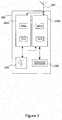
- FIG 2 shows an electronic device 200 in accordance with examples of the present invention.
- the electronic device 200 may be any type of electronic device, such as a mobile phone, laptop, PDA etc. but is shown as a smartphone 200 in Figure 200 for the purposes of explanation.
- the smartphone 200 comprises a first processing module (processor-memory pair) 202a, a second processing module (processor-memory pair) 202b, a communications interface 205, a battery 209, and a secondary (backup) power source 210.
- the smartphone 200 may comprise more components than shown, for example a user interface such as a graphical touch-screen interface.
- the battery 209 comprises one or more internal rechargeable batteries. These may be, for example, lithium-ion batteries.
- An internal battery may be charged using a charging port (not shown in Figure 2 ) by the user connecting a charging cable to the charging port 111 in order to connect the electronic device to an external e.g. mains power supply., or by a wireless charging mechanism.
- the communications interface 205 comprises one or more wired and/or wireless interfaces to provide at least one wired or wireless connection such as WiFi, BlueTooth, Ethernet, ZigBee, or cellular connection (e.g. 2G, 3G, 4G etc.).
- the communications interface 205 may provide for both transmission and reception of data signals (i.e. the communications interface 205 is a transceiver) but it is not excluded that, when the communications interface 205 comprises multiple interfaces, separate interfaces provide for transmission (a transmitter) and reception (a receiver) of signals.
- the first memory 207a comprises one or more computer storage units such as one or more RAM or ROM devices such as solid-state memories, hard drives etc.
- the first memory 207a is used by the first processor 201a during normal functioning of the device when the battery 209 is charged.
- the second memory 207b comprises one or more computer storage units such as one or more RAM or ROM devices such as solid-state memories, hard drives etc.
- the second memory 207b is a non-volatile memory which retains the data stored therein upon loss of power.
- the first processor 201a comprises one or more processing units such as one or more individual CPUs as known in the art and is operatively coupled to at least communications interface 205, first memory 207a, second memory 207b, and battery 209 by the one or more wired connections as mentioned above.
- the second processor 201b comprises one or more processing units such as one or more individual CPUs as known in the art.
- the second processor 201b is operatively coupled to at least second memory 207b, and secondary power source 210 by the one or more wired connections.
- the processing modules 202a, 202b are shown as distinct processor-memory pairs, that is, the first pair 202a is formed of first processor 201a and first memory 207a and the second pair is formed of second processor 201b and second memory 207b.
- these are functional blocks for the purposes of understanding only; in practice, operations attributed herein to the separate processors 201a and 201b could be performed by a single processor, and likewise the functionality of memories 207a and 207b could be performed by a single memory unit.
- memories 207a and 207b could be implemented as separate memory locations on the same physical electronic storage unit. So, in some examples, there may be for example a single processor but two separate memories.
- the processing modules 202a, 202b are shown separately in Figure 2 and may, for example, represent two separate printed circuit boards (PCBs) 202a, 202b each comprising a processor and a memory.
- PCBs printed circuit boards
- Both the first PCB 202a and second PCB 202b are connected to the battery 209 and configured to be powered by electrical current from the battery. Only the second PCB 202b is connected to the secondary power source 210 and configured to be powered by electrical current therefrom. Both the first PCB 202a and second PCB 202b are connected to the communications interface 205 and thereby enabled for wired and/or wireless communications.
- Processor 201 a may be considered the "main” or “primary” processor in that it is configured to perform computations in dependence on user input received from a user interface (not shown in Figure 2 ) and communications interface 205 in a manner well known in the art.
- the first processor 201a has access to the first memory 207a for use in performing these tasks, i.e. the first processor 201a is configured to store and retrieve data from memory 207a during normal operation of the smartphone 200.
- the first PCB 202a may be considered the "main” or “primary” PCB in that it comprises the main processor 201 a and an associated "main” memory 207a.
- the second PCB 201b may be considered an "emergency" or “backup” PCB (comprising a “backup” processor 201b and “backup memory” 207b).
- the second PCB 201b is lower power than the main PCB 202a (i.e. requires less electrical power in order to operate). This may be achieved using a lower power processor and/or memory.
- the first processing module 202a performs the normal functionality of the smartphone 202 by the processor 201 processing various processing tasks which herein refers to any computation of data to be performed by a processor in cooperation with any input device, output device, memory etc. and therefore covers both low-level tasks such as individual mathematical or logical operations on a CPU of the processor and high-level tasks such saving a document or sending a message.
- Tasks may be queued on the first PCB 202a, i.e. stored in memory 207a (which may represent a register of processor 201 a) for execution by the first processor 201a.
- Data relating to one or more of these tasks is stored in (e.g. copied to) the second memory 207b. That is, the second PCB 202b may in effect replicate and copy tasks from the first PCB 202a, for example caching some important data to send via communication interface 205.
- This is represented in Figure 2 as a dotted arrow.
- the first processor 201a need only be capable of writing to memory 207b; it does not need to be able to read from memory 207b like processor 201b does (see below).
- a task may in general be, for example, sending and/or receiving a message (such as an SMS or MMS message or the like over a cellular network or over the Internet), sending and/or receiving an email, saving a file (such as an email, document, picture, etc.), or any other task the user may perform on the smartphone 200 such as viewing files, browsing the Internet, etc.
- the arrangement may be such that only data relating to "important" tasks is stored in (e.g. copied to) the second memory 207b.
- "Important" tasks may be for example one or more of sending and/or receiving a message or an email say. What constitutes an "important" task that is copied to the second memory 207b may be set by for example the user as a user-defined option or set once by the manufacturer of the device 200.
- the second processor 201b can access the second memory 207b storing these tasks and therefore the second PCB 202b is enabled to perform the tasks upon a criterion being met.
- the criterion for the second PCB 202b performing the tasks is electrical power being received from the secondary power source 210.
- the second PCB 202b receives power from the secondary power source 210 and, in response thereto, executes one or more of the stored task(s). That is, the second processor 201b retrieves the data stored in the second memory 207b in response to receiving electrical power from the secondary power source 210 and executes one or more of the task(s).
- the second PCB 202b is configured to perform the conditional execution of the stored tasks at least when the charge level of battery 209 falls below a predetermined charge level (e.g. 1% or 2% of maximum charge or so).
- a predetermined charge level e.g. 1% or 2% of maximum charge or so.
- the second PCB 202b can be configured to only perform these steps when the battery 209 is fully discharged (i.e. when the charge level of the battery 209 is 0% of maximum charge, or at least low enough that the electronic device 200 is no longer able to boot). That is, the threshold charge level triggering the second PCB 202b is preferably set to be equal to a minimum charge level required by the first PCB 202a to function (i.e. the charge level at which the first PCB 202a powers down).
- the second PCB 202b will not fetch the tasks from memory 207b and execute them immediately upon the battery 209 discharging, but will execute them at a later point in time when the secondary power source 210 generates power.
- the advantage of this is that the "leftover" tasks will be stored in (non-volatile) memory 207b indefinitely, and so if the user wishes to complete the tasks (e.g. if the user was in the middle of sending a message when the battery 209 ran out) then the user can do so by simply enabling the secondary power source 210. This is quicker than charging the battery 209 to complete the tasks as it does not require the entire phone 200 to be turned back on (i.e. rebooting the entire operating system).
- the secondary power source 210 may comprise any suitable source of electric current which is capable of providing sufficient power to the second PCB 202b for long enough for the second processor 201b to fetch and execute one or more of the stored tasks. Note that this power source does not need to be sufficiently powerful to power the entire phone 200.
- the secondary power source 210 may be a wind-up power supply comprising an electromagnetic dynamo which the user can activate using a handle.
- the secondary power source 210 may comprise a coil of wire for generating an electric current when it (by way of the entire electronic device 200) is passed through a magnetic field. This is especially useful in combination with an apparatus 300 for charging the electronic device 200 comprising a plurality of magnets 310 arranged vertically as shown in Figure 3 .
- the apparatus 300 comprises a tall (e.g. more than ten metres, fifty metres, or one hundred metres in height) shaft composed of a hollow interior and an opening at the top through which the user's phone 200 may be dropped.
- the apparatus 300 may be installed on the side of a building 350 as shown in Figure 3 , on the inside of a building 350 (not shown), may be installed on the exterior or interior of any other structure such as a sculpture, or may be free-standing.
- the apparatus 300 may be installed in conjunction with a device 302 for minimising damage to the phone 200 (i.e. a catching mechanism), such as a cushion or spring device or the like. This is particularly useful for examples in which the apparatus 300 is tall enough that an unacceptable level of damage to the phone may occur, as in the example of Figure 3 in which the apparatus may be fifty metres, one hundred metres, or even more, depending on the building 350.
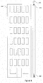
- Figure 4 shows a close up of a section of the apparatus 300.
- a plurality of magnets 310 is disposed along the length of the apparatus 300.
- the magnets 310 may be on the exterior and/or interior of the shaft of the apparatus 300. What matters is that they create a magnetic field at the centre of the apparatus 300, or, in any case, wherever the phone 200 will fall when dropped through the shaft.
- This example of the secondary power source 210 (comprising a coil 210 on the phone 200) being initiated by dropping the phone 200 through a "charging apparatus" 300 is particularly advantageous as it does not rely on any external power supply which other charging methods require (e.g. a mains power supply relies on power from the grid), and is simple and quick for the user to enact.
- the task when the user's phone 200 runs out of power in the middle an important task (e.g. sending or receiving a message or email or the like), the task will be saved to memory 207b, and the user can ensure this task gets completed by simply dropping his phone through the apparatus 300.
- the magnetic field from the magnets 310 induces a current in the coil 210, which (as described above) causes the second PCB 202b to "power up": the second processor 201b retrieves the task from memory 207b and executes it (the message is sent).
- the apparatus 300 may be provided with an elevating apparatus for lifting the phone 200 to the top of the apparatus and dropping it. This saves the user needing to be at the top of the apparatus 300 or from having to travel to the top of the apparatus 300.
- the apparatus 300 may be provided with additional openings at various different heights on the shaft, so that the user (and other users) may insert their phones into the shaft of the apparatus 300 from the various different heights. This has the advantage that a user does not need to travel all the way to the top of the apparatus 300 to perform the drop; he need only travel to the closest opening.
- the damage-minimising device 302 is preferable, in that it increases the chances that the phone 200 will be functional after the drop, but is not essential. For example, in an emergency situation in which the user is in the middle of sending an SOS message when the battery 209 runs out, it may be sufficient that the SOS message is sent regardless of the state of the phone 200 afterwards - particularly when the user has no other means of charging the phone 200.
- processor or processing system or circuitry referred to herein may in practice be provided by a single chip or integrated circuit or plural chips or integrated circuits, optionally provided as a chipset, an application-specific integrated circuit (ASIC), field-programmable gate array (FPGA), digital signal processor (DSP), graphics processing units (GPUs), etc.
- the chip or chips may comprise circuitry (as well as possibly firmware) for embodying at least one or more of a data processor or processors and a digital signal processor or processors, which are configurable so as to operate in accordance with the exemplary embodiments.
- the exemplary embodiments may be implemented at least in part by computer software stored in (non-transitory) memory and executable by the processor, or by hardware, or by a combination of tangibly stored software and hardware (and tangibly stored firmware).
Landscapes
- Engineering & Computer Science (AREA)
- Theoretical Computer Science (AREA)
- Physics & Mathematics (AREA)
- General Engineering & Computer Science (AREA)
- General Physics & Mathematics (AREA)
- Power Engineering (AREA)
- Charge And Discharge Circuits For Batteries Or The Like (AREA)
- Telephone Function (AREA)
- Power Sources (AREA)
Abstract
Description
- The present disclosure relates to an electronic device and a method of operating an electronic device.
- Electronic devices have become ubiquitous in modern society; many people own at least one personal electronic device such as a smartphones, tablet, laptop etc. Portable electronic devices are often equipped with an internal power supply (e.g. a battery) which requires charging from time to time. This is usually carried out by using a charging cable to connect the electronic device to a mains outlet. It can be a problem for the user when the battery becomes discharged.
- According to a first aspect disclosed herein, there is provided a method of operating an electronic device comprising an internal battery and a secondary power source, the method comprising: when a charge level of the internal battery is above a threshold charge level: executing a plurality of tasks on a processor of the electronic device; and storing data concerning at least one of the tasks to a memory internal to the electronic device; when the charge level of the internal battery is below the threshold charge level: retrieving the data concerning the at least one task from the memory in response to receiving electrical power from the secondary power source; and executing the at least one task.
- In an example, the electronic device comprises: a first processor being the processor on which the plurality of tasks is executed, and is configured to perform said storing data concerning at least one of the tasks to the memory; and a second processor configured to perform said retrieving the data concerning the at least one task from the memory and executing the at least one task.
- In an example, a power requirement of the second processor is lower than a power requirement of the first processor.
- In an example, the electronic device comprises: a first memory for use by the processor when the charge level of the internal battery is above a threshold charge level; and a second memory being the memory to which data concerning at least one of the tasks is stored.
- In an example, the secondary power source comprises a coil internal to the electronic device which is arranged to generate current upon the electronic device being passed through a magnetic field.
- In an example, the magnetic field is provided by a plurality of magnets disposed on a vertical structure and passing the electronic device through the magnetic field comprises dropping the electronic device through the vertical structure.
- In an example, the magnets are permanent magnets.
- In an example, a catching mechanism is located below the vertical structure for catching the electronic device.
- In an example, the catching mechanism comprises at least one of a spring, net, or airbag.
- In an example, the vertical structure is installed at a building.
- In an example, the vertical structure comprises an elevating mechanism for lifting the electronic device to the top of the vertical structure.
- In an example, said at least one task comprises saving a file to an electronic storage device.
- In an example, said at least one task comprises sending or receiving a message using a communications interface of the electronic device.
- According to a second aspect disclosed herein, there is provided an electronic device comprising: a memory; an internal battery for powering the electronic device; a secondary power source; a processor configured to: when a charge level of the internal battery is above a threshold charge level, execute a plurality of tasks and store data concerning at least one of the tasks to a memory; and when the charge level of the internal battery is below the threshold charge level, retrieve the data concerning the at least one task from the memory in response to receiving electrical power from the secondary power source and execute the at least one task.
- In an example, the electronic device comprises: a first processor configured to perform said executing the plurality of tasks and said storing data concerning at least one of the tasks when the charge level of the internal battery is above the threshold charge level; and a second processor configured to perform said retrieving the data concerning the at least one task from the memory and said executing the at least one task when the charge level of the internal battery is below the threshold charge level.
- In an example, a power requirement of the second processor is lower than a power requirement of the first processor.
- In an example, the electronic device comprises: a first memory for use by the processor when the charge level of the internal battery is above a threshold charge level; and a second memory being the memory to which data concerning at least one of the tasks is stored.
- In an example, the secondary power source comprises a coil internal to the electronic device which is arranged to generate current upon the electronic device being passed through a magnetic field.
- In an example, the electronic device further comprises a communications interface; and wherein the at least one task comprises transmitting data using the communications interface.
- There may also be provided a computer program product comprising computer-executable code embodied on a computer-readable storage medium configured so as when executed by one or more processing units to perform a method as described above.
- To assist understanding of the present disclosure and to show how embodiments may be put into effect, reference is made by way of example to the accompanying drawings in which:
-
Figure 1 shows schematically an electronic device; -
Figure 2 shows schematically an example of an electronic device according to the present disclosure; -
Figure 3 shows an example of an apparatus installed at a building for generating electric current in accordance with the present disclosure; and -
Figure 4 shows a section of the apparatus ofFigure 3 in more detail. - When the internal rechargeable battery of an electronic device (such as a smartphone, tablet computer, etc.) runs out and can no longer provide sufficient current to power the device, an internal processor of the device is not able to execute processing tasks. A user of the device may find himself in the middle of one or more important tasks when the internal battery of the device runs out. This may be annoying (e.g. if the user is unable to access information such as a boarding pass on their smartphone) or even dangerous (e.g. if the user is unable to use their mobile phone to make an emergency call or to transmit their location to emergency services or a friend). Charging the internal battery may not always be possible (due to lack of time, or a power socket, charging cable etc.).
- In examples described herein, tasks to be executed on the electronic device are stored to a memory during normal operation. When power is received from a secondary power source, the electronic device retrieves the stored tasks and completes them. This allows the user of the device to complete the tasks by simply activating the secondary power source. The secondary power source may be considered a "backup" power source.
- In further examples, the memory is a non-volatile memory and the tasks stored therein are maintained even after the internal battery discharges. In these cases, the user is able to complete tasks by activating the secondary power source even after the internal battery discharges.
- The secondary (backup) power source may be an internal coil for generating current through electromagnetic induction. Hence, the user is then able to have the electronic device execute these tasks by simply moving the electronic device through a magnetic field, even if the internal battery is discharged. For example, a vertical shaft lined with magnets may be installed in a building through which users are able to drop their phones in order to perform the tasks (preferably with a soft landing at the base provided by a cushion and/or spring mechanism or the like).
-
Figure 1 shows an example of an existingelectronic device 100, the type of which has become very widespread in both availability to and uptake by consumers. Theelectronic device 100 comprises aprocessor 101, auser interface 103, acommunication interface 105, amemory 107, aninternal power supply 109, and acharging port 111. Theelectronic device 100 is shown inFigure 1 as asmartphone 100, but may be any other electronic device equipped with a processor for performing processing tasks, such as a laptop, or other computing device. Similarly, it is understood that real electronic devices comprise many more components, and that only the main components are shown inFigure 1 for the sake of simplicity. Theprocessor 101 is connected to each of theuser interface 103,communication interface 105,memory 107, andpower supply 109, by one or more wired connections for transferring power and/or data in the form of electrical signals. Thepower supply 109 is also connected to thecharging port 111 by one or more wired connections for transferring at least power and optionally data between thecharging port 111 and thepower supply 109. - The
user interface 103 is shown as a touch-screengraphical user interface 103 inFigure 1 but may be any other suitable user input device such as a microphone and/or physical keyboard. In any case, a user of theelectronic device 100 is able to use theuser interface 103 to provide input to theelectronic device 100. These inputs are received by theprocessor 101 for processing, as known in the art and so only described briefly (below), in order that the user may control the functioning of theelectronic device 100. - The
communications interface 105 comprises one or more wired and/or wireless interfaces to provide at least one wired or wireless connection such as WiFi, BlueTooth, Ethernet, ZigBee, or cellular connection (e.g. 2G, 3G, 4G etc.) as known in the art. Thecommunications interface 105 generally provides for both transmission and reception of data signals (i.e. thecommunications interface 105 is a transceiver) but it is not excluded that, when thecommunications interface 105 comprises multiple interfaces, separate interfaces provide for transmission (a transmitter) and reception (a receiver) of signals. - The
memory 107 is an internal memory of theelectronic device 100 and comprises one or more computer storage units such as one or more RAM or ROM devices such as solid-state memories, hard drives etc. Preferably, thememory 107 is a non-volatile memory which retains the data stored therein upon loss of power. - The
processor 101 comprises one or more processing units, including for example one or more individual CPUs (central processing units) as known in the art and is operatively coupled to each of theuser interface 103,communications interface 105, andmemory 107 by the one or more wired connections as mentioned above. Hence, theprocessor 101 is arranged in operation to receive data from and send data to each of theuser interface 103,communications interface 105, andmemory 107, for example, to perform read and write operations from and to thememory 107. - The
electronic device 100 is normally powered by theinternal power source 109 which provides power to theprocessor 101,user interface 103,communications interface 103, andmemory 107 as required. Theinternal power source 109 comprises one or more internal rechargeable batteries. These may be, for example, lithium-ion batteries. Theinternal battery 109 may be charged using the charging port 111 (i.e. by the user connecting a charging cable to the chargingport 111 in order to connect the electronic device to an external e.g. mains power supply.), or by a wireless charging mechanism, as known in the art. - As mentioned above, electronic devices such as
electronic device 100 shown inFigure 1 have become widespread and many users use a personal mobile phone every day. This comprises the user charging thebattery 109 using for example the chargingport 111, interacting with thephone 100 through the user interface 103 (or user interface devices) to provide input to and receive output from theprocessor 101, and sending and receiving data via thecommunications interface 105. For example, the user is able to compose a text message on a touchscreen providing agraphical user interface 103 to be sent over the Internet via for example a cellular or WiFi connection provided bycommunications interface 105. This is all very well known in the art and so not described in more detail here. -
Figure 2 shows anelectronic device 200 in accordance with examples of the present invention. Theelectronic device 200 may be any type of electronic device, such as a mobile phone, laptop, PDA etc. but is shown as asmartphone 200 in Figure 200 for the purposes of explanation. - The
smartphone 200 comprises a first processing module (processor-memory pair) 202a, a second processing module (processor-memory pair) 202b, acommunications interface 205, abattery 209, and a secondary (backup)power source 210. Thesmartphone 200 may comprise more components than shown, for example a user interface such as a graphical touch-screen interface. - The
battery 209 comprises one or more internal rechargeable batteries. These may be, for example, lithium-ion batteries. An internal battery may be charged using a charging port (not shown inFigure 2 ) by the user connecting a charging cable to the chargingport 111 in order to connect the electronic device to an external e.g. mains power supply., or by a wireless charging mechanism. - The
communications interface 205 comprises one or more wired and/or wireless interfaces to provide at least one wired or wireless connection such as WiFi, BlueTooth, Ethernet, ZigBee, or cellular connection (e.g. 2G, 3G, 4G etc.). Thecommunications interface 205 may provide for both transmission and reception of data signals (i.e. thecommunications interface 205 is a transceiver) but it is not excluded that, when thecommunications interface 205 comprises multiple interfaces, separate interfaces provide for transmission (a transmitter) and reception (a receiver) of signals. - The
first memory 207a comprises one or more computer storage units such as one or more RAM or ROM devices such as solid-state memories, hard drives etc. Thefirst memory 207a is used by thefirst processor 201a during normal functioning of the device when thebattery 209 is charged. - Similarly, the
second memory 207b comprises one or more computer storage units such as one or more RAM or ROM devices such as solid-state memories, hard drives etc. Preferably, thesecond memory 207b is a non-volatile memory which retains the data stored therein upon loss of power. - The
first processor 201a comprises one or more processing units such as one or more individual CPUs as known in the art and is operatively coupled to atleast communications interface 205,first memory 207a,second memory 207b, andbattery 209 by the one or more wired connections as mentioned above. - Similarly, the
second processor 201b comprises one or more processing units such as one or more individual CPUs as known in the art. Thesecond processor 201b is operatively coupled to at leastsecond memory 207b, andsecondary power source 210 by the one or more wired connections. - The
processing modules first pair 202a is formed offirst processor 201a andfirst memory 207a and the second pair is formed ofsecond processor 201b andsecond memory 207b. However, these are functional blocks for the purposes of understanding only; in practice, operations attributed herein to theseparate processors memories memories processing modules Figure 2 and may, for example, represent two separate printed circuit boards (PCBs) 202a, 202b each comprising a processor and a memory. - Both the
first PCB 202a andsecond PCB 202b are connected to thebattery 209 and configured to be powered by electrical current from the battery. Only thesecond PCB 202b is connected to thesecondary power source 210 and configured to be powered by electrical current therefrom. Both thefirst PCB 202a andsecond PCB 202b are connected to thecommunications interface 205 and thereby enabled for wired and/or wireless communications. -
Processor 201 a may be considered the "main" or "primary" processor in that it is configured to perform computations in dependence on user input received from a user interface (not shown inFigure 2 ) and communications interface 205 in a manner well known in the art. Thefirst processor 201a has access to thefirst memory 207a for use in performing these tasks, i.e. thefirst processor 201a is configured to store and retrieve data frommemory 207a during normal operation of thesmartphone 200. Similarly, thefirst PCB 202a may be considered the "main" or "primary" PCB in that it comprises themain processor 201 a and an associated "main"memory 207a. - The
second PCB 201b may be considered an "emergency" or "backup" PCB (comprising a "backup"processor 201b and "backup memory" 207b). Preferably, thesecond PCB 201b is lower power than themain PCB 202a (i.e. requires less electrical power in order to operate). This may be achieved using a lower power processor and/or memory. - In operation, the
first processing module 202a performs the normal functionality of the smartphone 202 by the processor 201 processing various processing tasks which herein refers to any computation of data to be performed by a processor in cooperation with any input device, output device, memory etc. and therefore covers both low-level tasks such as individual mathematical or logical operations on a CPU of the processor and high-level tasks such saving a document or sending a message. - Tasks may be queued on the
first PCB 202a, i.e. stored inmemory 207a (which may represent a register ofprocessor 201 a) for execution by thefirst processor 201a. Data relating to one or more of these tasks is stored in (e.g. copied to) thesecond memory 207b. That is, thesecond PCB 202b may in effect replicate and copy tasks from thefirst PCB 202a, for example caching some important data to send viacommunication interface 205. This is represented inFigure 2 as a dotted arrow. Note that thefirst processor 201a need only be capable of writing tomemory 207b; it does not need to be able to read frommemory 207b likeprocessor 201b does (see below). - A task may in general be, for example, sending and/or receiving a message (such as an SMS or MMS message or the like over a cellular network or over the Internet), sending and/or receiving an email, saving a file (such as an email, document, picture, etc.), or any other task the user may perform on the
smartphone 200 such as viewing files, browsing the Internet, etc. The arrangement may be such that only data relating to "important" tasks is stored in (e.g. copied to) thesecond memory 207b. "Important" tasks may be for example one or more of sending and/or receiving a message or an email say. What constitutes an "important" task that is copied to thesecond memory 207b may be set by for example the user as a user-defined option or set once by the manufacturer of thedevice 200. - The
second processor 201b can access thesecond memory 207b storing these tasks and therefore thesecond PCB 202b is enabled to perform the tasks upon a criterion being met. The criterion for thesecond PCB 202b performing the tasks is electrical power being received from thesecondary power source 210. Once thesecondary power source 210 is activated, thesecond PCB 202b receives power from thesecondary power source 210 and, in response thereto, executes one or more of the stored task(s). That is, thesecond processor 201b retrieves the data stored in thesecond memory 207b in response to receiving electrical power from thesecondary power source 210 and executes one or more of the task(s). - The
second PCB 202b is configured to perform the conditional execution of the stored tasks at least when the charge level ofbattery 209 falls below a predetermined charge level (e.g. 1% or 2% of maximum charge or so). For example, thesecond PCB 202b can be configured to only perform these steps when thebattery 209 is fully discharged (i.e. when the charge level of thebattery 209 is 0% of maximum charge, or at least low enough that theelectronic device 200 is no longer able to boot). That is, the threshold charge level triggering thesecond PCB 202b is preferably set to be equal to a minimum charge level required by thefirst PCB 202a to function (i.e. the charge level at which thefirst PCB 202a powers down). - Hence, in this example, the
second PCB 202b will not fetch the tasks frommemory 207b and execute them immediately upon thebattery 209 discharging, but will execute them at a later point in time when thesecondary power source 210 generates power. The advantage of this is that the "leftover" tasks will be stored in (non-volatile)memory 207b indefinitely, and so if the user wishes to complete the tasks (e.g. if the user was in the middle of sending a message when thebattery 209 ran out) then the user can do so by simply enabling thesecondary power source 210. This is quicker than charging thebattery 209 to complete the tasks as it does not require theentire phone 200 to be turned back on (i.e. rebooting the entire operating system). - The
secondary power source 210 may comprise any suitable source of electric current which is capable of providing sufficient power to thesecond PCB 202b for long enough for thesecond processor 201b to fetch and execute one or more of the stored tasks. Note that this power source does not need to be sufficiently powerful to power theentire phone 200. For example, thesecondary power source 210 may be a wind-up power supply comprising an electromagnetic dynamo which the user can activate using a handle. - As another example, the
secondary power source 210 may comprise a coil of wire for generating an electric current when it (by way of the entire electronic device 200) is passed through a magnetic field. This is especially useful in combination with anapparatus 300 for charging theelectronic device 200 comprising a plurality ofmagnets 310 arranged vertically as shown inFigure 3 . - The
apparatus 300 comprises a tall (e.g. more than ten metres, fifty metres, or one hundred metres in height) shaft composed of a hollow interior and an opening at the top through which the user'sphone 200 may be dropped. Theapparatus 300 may be installed on the side of abuilding 350 as shown inFigure 3 , on the inside of a building 350 (not shown), may be installed on the exterior or interior of any other structure such as a sculpture, or may be free-standing. Theapparatus 300 may be installed in conjunction with adevice 302 for minimising damage to the phone 200 (i.e. a catching mechanism), such as a cushion or spring device or the like. This is particularly useful for examples in which theapparatus 300 is tall enough that an unacceptable level of damage to the phone may occur, as in the example ofFigure 3 in which the apparatus may be fifty metres, one hundred metres, or even more, depending on thebuilding 350. -
Figure 4 shows a close up of a section of theapparatus 300. As shown, a plurality ofmagnets 310 is disposed along the length of theapparatus 300. Themagnets 310 may be on the exterior and/or interior of the shaft of theapparatus 300. What matters is that they create a magnetic field at the centre of theapparatus 300, or, in any case, wherever thephone 200 will fall when dropped through the shaft. - This example of the secondary power source 210 (comprising a
coil 210 on the phone 200) being initiated by dropping thephone 200 through a "charging apparatus" 300 is particularly advantageous as it does not rely on any external power supply which other charging methods require (e.g. a mains power supply relies on power from the grid), and is simple and quick for the user to enact. - Hence, in these examples, when the user's
phone 200 runs out of power in the middle an important task (e.g. sending or receiving a message or email or the like), the task will be saved tomemory 207b, and the user can ensure this task gets completed by simply dropping his phone through theapparatus 300. As thephone 200 falls, the magnetic field from themagnets 310 induces a current in thecoil 210, which (as described above) causes thesecond PCB 202b to "power up": thesecond processor 201b retrieves the task frommemory 207b and executes it (the message is sent). - The
apparatus 300 may be provided with an elevating apparatus for lifting thephone 200 to the top of the apparatus and dropping it. This saves the user needing to be at the top of theapparatus 300 or from having to travel to the top of theapparatus 300. - The
apparatus 300 may be provided with additional openings at various different heights on the shaft, so that the user (and other users) may insert their phones into the shaft of theapparatus 300 from the various different heights. This has the advantage that a user does not need to travel all the way to the top of theapparatus 300 to perform the drop; he need only travel to the closest opening. - The damage-minimising
device 302 is preferable, in that it increases the chances that thephone 200 will be functional after the drop, but is not essential. For example, in an emergency situation in which the user is in the middle of sending an SOS message when thebattery 209 runs out, it may be sufficient that the SOS message is sent regardless of the state of thephone 200 afterwards - particularly when the user has no other means of charging thephone 200. - It will be understood that the processor or processing system or circuitry referred to herein may in practice be provided by a single chip or integrated circuit or plural chips or integrated circuits, optionally provided as a chipset, an application-specific integrated circuit (ASIC), field-programmable gate array (FPGA), digital signal processor (DSP), graphics processing units (GPUs), etc. The chip or chips may comprise circuitry (as well as possibly firmware) for embodying at least one or more of a data processor or processors and a digital signal processor or processors, which are configurable so as to operate in accordance with the exemplary embodiments. In this regard, the exemplary embodiments may be implemented at least in part by computer software stored in (non-transitory) memory and executable by the processor, or by hardware, or by a combination of tangibly stored software and hardware (and tangibly stored firmware).
- Reference is made herein to data storage for storing data. This may be provided by a single device or by plural devices. Suitable devices include for example a hard disk and non-volatile semiconductor memory.
- The examples described herein are to be understood as illustrative examples of embodiments of the invention. Further embodiments and examples are envisaged. Any feature described in relation to any one example or embodiment may be used alone or in combination with other features. In addition, any feature described in relation to any one example or embodiment may also be used in combination with one or more features of any other of the examples or embodiments, or any combination of any other of the examples or embodiments. Furthermore, equivalents and modifications not described herein may also be employed within the scope of the invention, which is defined in the claims.
Claims (15)
- A method of operating an electronic device comprising an internal battery and a secondary power source, the method comprising:when a charge level of the internal battery is above a threshold charge level: executing a plurality of tasks on a processor of the electronic device; and storing data concerning at least one of the tasks to a memory internal to the electronic device;when the charge level of the internal battery is below the threshold charge level: retrieving the data concerning the at least one task from the memory in response to receiving electrical power from the secondary power source; and executing the at least one task.
- The method according to claim 1, wherein the electronic device comprises:a first processor being the processor on which the plurality of tasks is executed, and is configured to perform said storing data concerning at least one of the tasks to the memory; anda second processor configured to perform said retrieving the data concerning the at least one task from the memory and executing the at least one task.
- The method according to claim 2, wherein a power requirement of the second processor is lower than a power requirement of the first processor.
- The method according to any preceding claim, wherein the electronic device comprises:a first memory for use by the processor when the charge level of the internal battery is above a threshold charge level; anda second memory being the memory to which data concerning at least one of the tasks is stored.
- The method according to any preceding claim, wherein the secondary power source comprises a coil internal to the electronic device which is arranged to generate current upon the electronic device being passed through a magnetic field.
- The method according to claim 5, wherein the magnetic field is provided by a plurality of magnets disposed on a vertical structure and passing the electronic device through the magnetic field comprises dropping the electronic device through the vertical structure.
- The method according to any preceding claim, wherein said at least one task comprises saving a file to an electronic storage device.
- The method according to any preceding claim, wherein said at least one task comprises sending or receiving a message using a communications interface of the electronic device.
- An electronic device comprising:a memory;an internal battery for powering the electronic device;a secondary power source; anda processor configured to: when a charge level of the internal battery is above a threshold charge level, execute a plurality of tasks and store data concerning at least one of the tasks to a memory; and when the charge level of the internal battery is below the threshold charge level, retrieve the data concerning the at least one task from the memory in response to receiving electrical power from the secondary power source and execute the at least one task.
- The electronic device according to claim 9, wherein the electronic device comprises:a first processor configured to perform said executing the plurality of tasks and said storing data concerning at least one of the tasks when the charge level of the internal battery is above the threshold charge level; anda second processor configured to perform said retrieving the data concerning the at least one task from the memory and said executing the at least one task when the charge level of the internal battery is below the threshold charge level.
- The electronic device according to claim 10, wherein a power requirement of the second processor is lower than a power requirement of the first processor.
- The electronic device according to any of claims 9 to 11, wherein the electronic device comprises:a first memory for use by the processor when the charge level of the internal battery is above a threshold charge level; anda second memory being the memory to which data concerning at least one of the tasks is stored.
- The electronic device according to any of claims 9 to 12, wherein the secondary power source comprises a coil internal to the electronic device which is arranged to generate current upon the electronic device being passed through a magnetic field.
- The electronic device according to any of claims 9 to 13, further comprising a communications interface; and wherein the at least one task comprises transmitting data using the communications interface.
- A computer program product comprising computer-executable code embodied on a computer-readable storage medium configured so as when executed by one or more processing units to perform the method steps of any of claims 1 to 8.
Priority Applications (2)
| Application Number | Priority Date | Filing Date | Title |
|---|---|---|---|
| EP17174558.1A EP3413161B1 (en) | 2017-06-06 | 2017-06-06 | Electronic device and method of operating an electronic device |
| TR2017/08959A TR201708959A2 (en) | 2017-06-06 | 2017-06-16 | ELECTRONIC DEVICE AND METHOD OF OPERATING AN ELECTRONIC DEVICE |
Applications Claiming Priority (1)
| Application Number | Priority Date | Filing Date | Title |
|---|---|---|---|
| EP17174558.1A EP3413161B1 (en) | 2017-06-06 | 2017-06-06 | Electronic device and method of operating an electronic device |
Publications (2)
| Publication Number | Publication Date |
|---|---|
| EP3413161A1 true EP3413161A1 (en) | 2018-12-12 |
| EP3413161B1 EP3413161B1 (en) | 2022-04-06 |
Family
ID=59054994
Family Applications (1)
| Application Number | Title | Priority Date | Filing Date |
|---|---|---|---|
| EP17174558.1A Active EP3413161B1 (en) | 2017-06-06 | 2017-06-06 | Electronic device and method of operating an electronic device |
Country Status (2)
| Country | Link |
|---|---|
| EP (1) | EP3413161B1 (en) |
| TR (1) | TR201708959A2 (en) |
Cited By (1)
| Publication number | Priority date | Publication date | Assignee | Title |
|---|---|---|---|---|
| CN113394471A (en) * | 2020-03-13 | 2021-09-14 | 北京小米移动软件有限公司 | Charging method and device, electronic device and storage medium |
Citations (3)
| Publication number | Priority date | Publication date | Assignee | Title |
|---|---|---|---|---|
| US20100124896A1 (en) * | 2008-11-20 | 2010-05-20 | Kumar Dinesh J | Dual battery mobile phone |
| US20150207361A1 (en) * | 2014-01-22 | 2015-07-23 | Industry-University Cooperation Foundation Hanyang University | Method and apparatus for changing operation status of electronic device |
| US20150303735A1 (en) * | 2012-11-29 | 2015-10-22 | Nokia Corporation | An inductive energy transfer coil structure |
-
2017
- 2017-06-06 EP EP17174558.1A patent/EP3413161B1/en active Active
- 2017-06-16 TR TR2017/08959A patent/TR201708959A2/en unknown
Patent Citations (3)
| Publication number | Priority date | Publication date | Assignee | Title |
|---|---|---|---|---|
| US20100124896A1 (en) * | 2008-11-20 | 2010-05-20 | Kumar Dinesh J | Dual battery mobile phone |
| US20150303735A1 (en) * | 2012-11-29 | 2015-10-22 | Nokia Corporation | An inductive energy transfer coil structure |
| US20150207361A1 (en) * | 2014-01-22 | 2015-07-23 | Industry-University Cooperation Foundation Hanyang University | Method and apparatus for changing operation status of electronic device |
Cited By (2)
| Publication number | Priority date | Publication date | Assignee | Title |
|---|---|---|---|---|
| CN113394471A (en) * | 2020-03-13 | 2021-09-14 | 北京小米移动软件有限公司 | Charging method and device, electronic device and storage medium |
| CN113394471B (en) * | 2020-03-13 | 2023-05-02 | 北京小米移动软件有限公司 | Charging method and device, electronic equipment and storage medium |
Also Published As
| Publication number | Publication date |
|---|---|
| EP3413161B1 (en) | 2022-04-06 |
| TR201708959A2 (en) | 2018-12-21 |
Similar Documents
| Publication | Publication Date | Title |
|---|---|---|
| CN105743158B (en) | Apparatus and method for charging an electronic device having a battery | |
| US10135274B2 (en) | Charging circuit and electronic device having the same | |
| US20190332141A1 (en) | Method for Detecting Wearing-State and Wearable Device | |
| JP6400124B2 (en) | Method and system and apparatus for controlling an intelligent wearable device | |
| US20210175735A1 (en) | Charging circuit, electronic device, charging control method and device | |
| EP2398286B1 (en) | Method for power management of mobile communication terminal and mobile communication terminal using this method | |
| US20120071215A1 (en) | Method and Apparatus for Controlling a Smart Phone Charger | |
| CN105098848A (en) | Wireless charging method and system and mobile terminal | |
| CN103532182A (en) | Charging assembly, portable electronic equipment and protection shell | |
| KR20100072857A (en) | Controlling method of interrupt and potable device using the same | |
| CN109075611B (en) | Wireless charging | |
| CN114498865B (en) | Charging circuit, charging control method and electronic device | |
| CN113258652A (en) | Battery control system and method and electronic equipment | |
| CN104184498A (en) | Apparatus and method for providing battery information, and user terminal therefor | |
| US9769757B2 (en) | Method and apparatus for saving power in access point network | |
| CN114048168B (en) | Electronic archive archiving method, device, equipment, system and storage medium | |
| EP3138178B1 (en) | Wireless charging method and system, and mobile terminal | |
| CN106507269B (en) | Data migration method and terminal equipment | |
| CN112867120B (en) | Low power consumption control system, method, computer device and readable storage medium | |
| CN104407804A (en) | Screen capturing method and screen capturing device as well as electronic device | |
| US20210294766A1 (en) | Terminal and type c interface anti-corrosion method | |
| CN107800881A (en) | Mobile terminal and mobile terminal guard method | |
| CN103840249A (en) | System involving portable electronic device and method related thereto | |
| EP2587617B1 (en) | Apparatus and method for controlling charge current in portable terminal | |
| CN106060381A (en) | Camera and docking station control method and system |
Legal Events
| Date | Code | Title | Description |
|---|---|---|---|
| PUAI | Public reference made under article 153(3) epc to a published international application that has entered the european phase |
Free format text: ORIGINAL CODE: 0009012 |
|
| STAA | Information on the status of an ep patent application or granted ep patent |
Free format text: STATUS: THE APPLICATION HAS BEEN PUBLISHED |
|
| AK | Designated contracting states |
Kind code of ref document: A1 Designated state(s): AL AT BE BG CH CY CZ DE DK EE ES FI FR GB GR HR HU IE IS IT LI LT LU LV MC MK MT NL NO PL PT RO RS SE SI SK SM TR |
|
| AX | Request for extension of the european patent |
Extension state: BA ME |
|
| STAA | Information on the status of an ep patent application or granted ep patent |
Free format text: STATUS: REQUEST FOR EXAMINATION WAS MADE |
|
| 17P | Request for examination filed |
Effective date: 20190610 |
|
| RBV | Designated contracting states (corrected) |
Designated state(s): AL AT BE BG CH CY CZ DE DK EE ES FI FR GB GR HR HU IE IS IT LI LT LU LV MC MK MT NL NO PL PT RO RS SE SI SK SM TR |
|
| STAA | Information on the status of an ep patent application or granted ep patent |
Free format text: STATUS: EXAMINATION IS IN PROGRESS |
|
| 17Q | First examination report despatched |
Effective date: 20191008 |
|
| RIC1 | Information provided on ipc code assigned before grant |
Ipc: G06F 1/3293 20190101ALI20210920BHEP Ipc: G06F 1/3212 20190101ALI20210920BHEP Ipc: G06F 1/32 20190101ALI20210920BHEP Ipc: G06F 1/26 20060101AFI20210920BHEP |
|
| GRAP | Despatch of communication of intention to grant a patent |
Free format text: ORIGINAL CODE: EPIDOSNIGR1 |
|
| STAA | Information on the status of an ep patent application or granted ep patent |
Free format text: STATUS: GRANT OF PATENT IS INTENDED |
|
| INTG | Intention to grant announced |
Effective date: 20211110 |
|
| GRAS | Grant fee paid |
Free format text: ORIGINAL CODE: EPIDOSNIGR3 |
|
| GRAA | (expected) grant |
Free format text: ORIGINAL CODE: 0009210 |
|
| STAA | Information on the status of an ep patent application or granted ep patent |
Free format text: STATUS: THE PATENT HAS BEEN GRANTED |
|
| AK | Designated contracting states |
Kind code of ref document: B1 Designated state(s): AL AT BE BG CH CY CZ DE DK EE ES FI FR GB GR HR HU IE IS IT LI LT LU LV MC MK MT NL NO PL PT RO RS SE SI SK SM TR |
|
| REG | Reference to a national code |
Ref country code: GB Ref legal event code: FG4D |
|
| REG | Reference to a national code |
Ref country code: CH Ref legal event code: EP |
|
| REG | Reference to a national code |
Ref country code: AT Ref legal event code: REF Ref document number: 1481973 Country of ref document: AT Kind code of ref document: T Effective date: 20220415 |
|
| REG | Reference to a national code |
Ref country code: DE Ref legal event code: R096 Ref document number: 602017055449 Country of ref document: DE |
|
| REG | Reference to a national code |
Ref country code: IE Ref legal event code: FG4D |
|
| REG | Reference to a national code |
Ref country code: DE Ref legal event code: R081 Ref document number: 602017055449 Country of ref document: DE Owner name: VESTEL ELEKTRONIK SANAYI VE TICARET A.S., TR Free format text: FORMER OWNER: VESTEL ELEKTRONIK SANAYI VE TICARET A.S., MANISA, TR Ref country code: DE Ref legal event code: R081 Ref document number: 602017055449 Country of ref document: DE Owner name: OEZYEGIN UENIVERSITESI, ISTANBUL, TR Free format text: FORMER OWNER: VESTEL ELEKTRONIK SANAYI VE TICARET A.S., MANISA, TR |
|
| REG | Reference to a national code |
Ref country code: LT Ref legal event code: MG9D |
|
| REG | Reference to a national code |
Ref country code: NL Ref legal event code: MP Effective date: 20220406 |
|
| REG | Reference to a national code |
Ref country code: AT Ref legal event code: MK05 Ref document number: 1481973 Country of ref document: AT Kind code of ref document: T Effective date: 20220406 |
|
| PG25 | Lapsed in a contracting state [announced via postgrant information from national office to epo] |
Ref country code: NL Free format text: LAPSE BECAUSE OF FAILURE TO SUBMIT A TRANSLATION OF THE DESCRIPTION OR TO PAY THE FEE WITHIN THE PRESCRIBED TIME-LIMIT Effective date: 20220406 |
|
| PG25 | Lapsed in a contracting state [announced via postgrant information from national office to epo] |
Ref country code: SE Free format text: LAPSE BECAUSE OF FAILURE TO SUBMIT A TRANSLATION OF THE DESCRIPTION OR TO PAY THE FEE WITHIN THE PRESCRIBED TIME-LIMIT Effective date: 20220406 Ref country code: PT Free format text: LAPSE BECAUSE OF FAILURE TO SUBMIT A TRANSLATION OF THE DESCRIPTION OR TO PAY THE FEE WITHIN THE PRESCRIBED TIME-LIMIT Effective date: 20220808 Ref country code: NO Free format text: LAPSE BECAUSE OF FAILURE TO SUBMIT A TRANSLATION OF THE DESCRIPTION OR TO PAY THE FEE WITHIN THE PRESCRIBED TIME-LIMIT Effective date: 20220706 Ref country code: LT Free format text: LAPSE BECAUSE OF FAILURE TO SUBMIT A TRANSLATION OF THE DESCRIPTION OR TO PAY THE FEE WITHIN THE PRESCRIBED TIME-LIMIT Effective date: 20220406 Ref country code: HR Free format text: LAPSE BECAUSE OF FAILURE TO SUBMIT A TRANSLATION OF THE DESCRIPTION OR TO PAY THE FEE WITHIN THE PRESCRIBED TIME-LIMIT Effective date: 20220406 Ref country code: GR Free format text: LAPSE BECAUSE OF FAILURE TO SUBMIT A TRANSLATION OF THE DESCRIPTION OR TO PAY THE FEE WITHIN THE PRESCRIBED TIME-LIMIT Effective date: 20220707 Ref country code: FI Free format text: LAPSE BECAUSE OF FAILURE TO SUBMIT A TRANSLATION OF THE DESCRIPTION OR TO PAY THE FEE WITHIN THE PRESCRIBED TIME-LIMIT Effective date: 20220406 Ref country code: ES Free format text: LAPSE BECAUSE OF FAILURE TO SUBMIT A TRANSLATION OF THE DESCRIPTION OR TO PAY THE FEE WITHIN THE PRESCRIBED TIME-LIMIT Effective date: 20220406 Ref country code: BG Free format text: LAPSE BECAUSE OF FAILURE TO SUBMIT A TRANSLATION OF THE DESCRIPTION OR TO PAY THE FEE WITHIN THE PRESCRIBED TIME-LIMIT Effective date: 20220706 Ref country code: AT Free format text: LAPSE BECAUSE OF FAILURE TO SUBMIT A TRANSLATION OF THE DESCRIPTION OR TO PAY THE FEE WITHIN THE PRESCRIBED TIME-LIMIT Effective date: 20220406 |
|
| PG25 | Lapsed in a contracting state [announced via postgrant information from national office to epo] |
Ref country code: RS Free format text: LAPSE BECAUSE OF FAILURE TO SUBMIT A TRANSLATION OF THE DESCRIPTION OR TO PAY THE FEE WITHIN THE PRESCRIBED TIME-LIMIT Effective date: 20220406 Ref country code: PL Free format text: LAPSE BECAUSE OF FAILURE TO SUBMIT A TRANSLATION OF THE DESCRIPTION OR TO PAY THE FEE WITHIN THE PRESCRIBED TIME-LIMIT Effective date: 20220406 Ref country code: LV Free format text: LAPSE BECAUSE OF FAILURE TO SUBMIT A TRANSLATION OF THE DESCRIPTION OR TO PAY THE FEE WITHIN THE PRESCRIBED TIME-LIMIT Effective date: 20220406 Ref country code: IS Free format text: LAPSE BECAUSE OF FAILURE TO SUBMIT A TRANSLATION OF THE DESCRIPTION OR TO PAY THE FEE WITHIN THE PRESCRIBED TIME-LIMIT Effective date: 20220806 |
|
| REG | Reference to a national code |
Ref country code: DE Ref legal event code: R097 Ref document number: 602017055449 Country of ref document: DE |
|
| PG25 | Lapsed in a contracting state [announced via postgrant information from national office to epo] |
Ref country code: SM Free format text: LAPSE BECAUSE OF FAILURE TO SUBMIT A TRANSLATION OF THE DESCRIPTION OR TO PAY THE FEE WITHIN THE PRESCRIBED TIME-LIMIT Effective date: 20220406 Ref country code: SK Free format text: LAPSE BECAUSE OF FAILURE TO SUBMIT A TRANSLATION OF THE DESCRIPTION OR TO PAY THE FEE WITHIN THE PRESCRIBED TIME-LIMIT Effective date: 20220406 Ref country code: RO Free format text: LAPSE BECAUSE OF FAILURE TO SUBMIT A TRANSLATION OF THE DESCRIPTION OR TO PAY THE FEE WITHIN THE PRESCRIBED TIME-LIMIT Effective date: 20220406 Ref country code: MC Free format text: LAPSE BECAUSE OF FAILURE TO SUBMIT A TRANSLATION OF THE DESCRIPTION OR TO PAY THE FEE WITHIN THE PRESCRIBED TIME-LIMIT Effective date: 20220406 Ref country code: EE Free format text: LAPSE BECAUSE OF FAILURE TO SUBMIT A TRANSLATION OF THE DESCRIPTION OR TO PAY THE FEE WITHIN THE PRESCRIBED TIME-LIMIT Effective date: 20220406 Ref country code: DK Free format text: LAPSE BECAUSE OF FAILURE TO SUBMIT A TRANSLATION OF THE DESCRIPTION OR TO PAY THE FEE WITHIN THE PRESCRIBED TIME-LIMIT Effective date: 20220406 Ref country code: CZ Free format text: LAPSE BECAUSE OF FAILURE TO SUBMIT A TRANSLATION OF THE DESCRIPTION OR TO PAY THE FEE WITHIN THE PRESCRIBED TIME-LIMIT Effective date: 20220406 |
|
| REG | Reference to a national code |
Ref country code: CH Ref legal event code: PL |
|
| PLBE | No opposition filed within time limit |
Free format text: ORIGINAL CODE: 0009261 |
|
| STAA | Information on the status of an ep patent application or granted ep patent |
Free format text: STATUS: NO OPPOSITION FILED WITHIN TIME LIMIT |
|
| REG | Reference to a national code |
Ref country code: BE Ref legal event code: MM Effective date: 20220630 |
|
| 26N | No opposition filed |
Effective date: 20230110 |
|
| PG25 | Lapsed in a contracting state [announced via postgrant information from national office to epo] |
Ref country code: AL Free format text: LAPSE BECAUSE OF FAILURE TO SUBMIT A TRANSLATION OF THE DESCRIPTION OR TO PAY THE FEE WITHIN THE PRESCRIBED TIME-LIMIT Effective date: 20220406 |
|
| PG25 | Lapsed in a contracting state [announced via postgrant information from national office to epo] |
Ref country code: LU Free format text: LAPSE BECAUSE OF NON-PAYMENT OF DUE FEES Effective date: 20220606 Ref country code: LI Free format text: LAPSE BECAUSE OF NON-PAYMENT OF DUE FEES Effective date: 20220630 Ref country code: IE Free format text: LAPSE BECAUSE OF NON-PAYMENT OF DUE FEES Effective date: 20220606 Ref country code: FR Free format text: LAPSE BECAUSE OF NON-PAYMENT OF DUE FEES Effective date: 20220606 Ref country code: CH Free format text: LAPSE BECAUSE OF NON-PAYMENT OF DUE FEES Effective date: 20220630 |
|
| PG25 | Lapsed in a contracting state [announced via postgrant information from national office to epo] |
Ref country code: SI Free format text: LAPSE BECAUSE OF FAILURE TO SUBMIT A TRANSLATION OF THE DESCRIPTION OR TO PAY THE FEE WITHIN THE PRESCRIBED TIME-LIMIT Effective date: 20220406 Ref country code: BE Free format text: LAPSE BECAUSE OF NON-PAYMENT OF DUE FEES Effective date: 20220630 |
|
| PG25 | Lapsed in a contracting state [announced via postgrant information from national office to epo] |
Ref country code: IT Free format text: LAPSE BECAUSE OF FAILURE TO SUBMIT A TRANSLATION OF THE DESCRIPTION OR TO PAY THE FEE WITHIN THE PRESCRIBED TIME-LIMIT Effective date: 20220406 |
|
| PG25 | Lapsed in a contracting state [announced via postgrant information from national office to epo] |
Ref country code: HU Free format text: LAPSE BECAUSE OF FAILURE TO SUBMIT A TRANSLATION OF THE DESCRIPTION OR TO PAY THE FEE WITHIN THE PRESCRIBED TIME-LIMIT; INVALID AB INITIO Effective date: 20170606 |
|
| PG25 | Lapsed in a contracting state [announced via postgrant information from national office to epo] |
Ref country code: MK Free format text: LAPSE BECAUSE OF FAILURE TO SUBMIT A TRANSLATION OF THE DESCRIPTION OR TO PAY THE FEE WITHIN THE PRESCRIBED TIME-LIMIT Effective date: 20220406 Ref country code: CY Free format text: LAPSE BECAUSE OF FAILURE TO SUBMIT A TRANSLATION OF THE DESCRIPTION OR TO PAY THE FEE WITHIN THE PRESCRIBED TIME-LIMIT Effective date: 20220406 |
|
| PG25 | Lapsed in a contracting state [announced via postgrant information from national office to epo] |
Ref country code: MT Free format text: LAPSE BECAUSE OF FAILURE TO SUBMIT A TRANSLATION OF THE DESCRIPTION OR TO PAY THE FEE WITHIN THE PRESCRIBED TIME-LIMIT Effective date: 20220406 |
|
| PG25 | Lapsed in a contracting state [announced via postgrant information from national office to epo] |
Ref country code: BG Free format text: LAPSE BECAUSE OF FAILURE TO SUBMIT A TRANSLATION OF THE DESCRIPTION OR TO PAY THE FEE WITHIN THE PRESCRIBED TIME-LIMIT Effective date: 20220406 |
|
| PG25 | Lapsed in a contracting state [announced via postgrant information from national office to epo] |
Ref country code: BG Free format text: LAPSE BECAUSE OF FAILURE TO SUBMIT A TRANSLATION OF THE DESCRIPTION OR TO PAY THE FEE WITHIN THE PRESCRIBED TIME-LIMIT Effective date: 20220406 |
|
| PGFP | Annual fee paid to national office [announced via postgrant information from national office to epo] |
Ref country code: DE Payment date: 20250618 Year of fee payment: 9 |
|
| REG | Reference to a national code |
Ref country code: DE Ref legal event code: R082 Ref document number: 602017055449 Country of ref document: DE Representative=s name: WESTPHAL, MUSSGNUG & PARTNER PATENTANWAELTE MI, DE |
|
| PGFP | Annual fee paid to national office [announced via postgrant information from national office to epo] |
Ref country code: GB Payment date: 20260629 Year of fee payment: 10 |
|
| PGFP | Annual fee paid to national office [announced via postgrant information from national office to epo] |
Ref country code: TR Payment date: 20260605 Year of fee payment: 10 |