EP3413096A1 - A method of dropping a plurality of probes intended to partially penetrate into a ground using a vegetation detection, and related system - Google Patents
A method of dropping a plurality of probes intended to partially penetrate into a ground using a vegetation detection, and related system Download PDFInfo
- Publication number
- EP3413096A1 EP3413096A1 EP18176442.4A EP18176442A EP3413096A1 EP 3413096 A1 EP3413096 A1 EP 3413096A1 EP 18176442 A EP18176442 A EP 18176442A EP 3413096 A1 EP3413096 A1 EP 3413096A1
- Authority
- EP
- European Patent Office
- Prior art keywords
- vegetation
- dropping area
- category
- ground surface
- information
- Prior art date
- Legal status (The legal status is an assumption and is not a legal conclusion. Google has not performed a legal analysis and makes no representation as to the accuracy of the status listed.)
- Granted
Links
Images



Classifications
-
- G—PHYSICS
- G01—MEASURING; TESTING
- G01V—GEOPHYSICS; GRAVITATIONAL MEASUREMENTS; DETECTING MASSES OR OBJECTS; TAGS
- G01V1/00—Seismology; Seismic or acoustic prospecting or detecting
- G01V1/02—Generating seismic energy
-
- G—PHYSICS
- G01—MEASURING; TESTING
- G01V—GEOPHYSICS; GRAVITATIONAL MEASUREMENTS; DETECTING MASSES OR OBJECTS; TAGS
- G01V1/00—Seismology; Seismic or acoustic prospecting or detecting
- G01V1/16—Receiving elements for seismic signals; Arrangements or adaptations of receiving elements
- G01V1/168—Deployment of receiver elements
-
- B—PERFORMING OPERATIONS; TRANSPORTING
- B64—AIRCRAFT; AVIATION; COSMONAUTICS
- B64D—EQUIPMENT FOR FITTING IN OR TO AIRCRAFT; FLIGHT SUITS; PARACHUTES; ARRANGEMENT OR MOUNTING OF POWER PLANTS OR PROPULSION TRANSMISSIONS IN AIRCRAFT
- B64D1/00—Dropping, ejecting, releasing or receiving articles, liquids, or the like, in flight
- B64D1/02—Dropping, ejecting, or releasing articles
-
- G—PHYSICS
- G01—MEASURING; TESTING
- G01S—RADIO DIRECTION-FINDING; RADIO NAVIGATION; DETERMINING DISTANCE OR VELOCITY BY USE OF RADIO WAVES; LOCATING OR PRESENCE-DETECTING BY USE OF THE REFLECTION OR RERADIATION OF RADIO WAVES; ANALOGOUS ARRANGEMENTS USING OTHER WAVES
- G01S17/00—Systems using the reflection or reradiation of electromagnetic waves other than radio waves, e.g. lidar systems
- G01S17/02—Systems using the reflection of electromagnetic waves other than radio waves
- G01S17/06—Systems determining position data of a target
-
- G—PHYSICS
- G01—MEASURING; TESTING
- G01S—RADIO DIRECTION-FINDING; RADIO NAVIGATION; DETERMINING DISTANCE OR VELOCITY BY USE OF RADIO WAVES; LOCATING OR PRESENCE-DETECTING BY USE OF THE REFLECTION OR RERADIATION OF RADIO WAVES; ANALOGOUS ARRANGEMENTS USING OTHER WAVES
- G01S17/00—Systems using the reflection or reradiation of electromagnetic waves other than radio waves, e.g. lidar systems
- G01S17/86—Combinations of lidar systems with systems other than lidar, radar or sonar, e.g. with direction finders
-
- G—PHYSICS
- G01—MEASURING; TESTING
- G01V—GEOPHYSICS; GRAVITATIONAL MEASUREMENTS; DETECTING MASSES OR OBJECTS; TAGS
- G01V1/00—Seismology; Seismic or acoustic prospecting or detecting
- G01V1/02—Generating seismic energy
- G01V1/04—Details
- G01V1/09—Transporting arrangements, e.g. on vehicles
-
- G—PHYSICS
- G01—MEASURING; TESTING
- G01V—GEOPHYSICS; GRAVITATIONAL MEASUREMENTS; DETECTING MASSES OR OBJECTS; TAGS
- G01V1/00—Seismology; Seismic or acoustic prospecting or detecting
- G01V1/16—Receiving elements for seismic signals; Arrangements or adaptations of receiving elements
- G01V1/162—Details
- G01V1/166—Arrangements for coupling receivers to the ground
-
- G—PHYSICS
- G01—MEASURING; TESTING
- G01V—GEOPHYSICS; GRAVITATIONAL MEASUREMENTS; DETECTING MASSES OR OBJECTS; TAGS
- G01V1/00—Seismology; Seismic or acoustic prospecting or detecting
- G01V1/16—Receiving elements for seismic signals; Arrangements or adaptations of receiving elements
- G01V1/20—Arrangements of receiving elements, e.g. geophone pattern
-
- G—PHYSICS
- G01—MEASURING; TESTING
- G01V—GEOPHYSICS; GRAVITATIONAL MEASUREMENTS; DETECTING MASSES OR OBJECTS; TAGS
- G01V3/00—Electric or magnetic prospecting or detecting; Measuring magnetic field characteristics of the earth, e.g. declination, deviation
- G01V3/15—Electric or magnetic prospecting or detecting; Measuring magnetic field characteristics of the earth, e.g. declination, deviation specially adapted for use during transport, e.g. by a person, vehicle or boat
- G01V3/16—Electric or magnetic prospecting or detecting; Measuring magnetic field characteristics of the earth, e.g. declination, deviation specially adapted for use during transport, e.g. by a person, vehicle or boat specially adapted for use from aircraft
-
- G—PHYSICS
- G06—COMPUTING OR CALCULATING; COUNTING
- G06V—IMAGE OR VIDEO RECOGNITION OR UNDERSTANDING
- G06V20/00—Scenes; Scene-specific elements
- G06V20/10—Terrestrial scenes
- G06V20/188—Vegetation
-
- B—PERFORMING OPERATIONS; TRANSPORTING
- B64—AIRCRAFT; AVIATION; COSMONAUTICS
- B64U—UNMANNED AERIAL VEHICLES [UAV]; EQUIPMENT THEREFOR
- B64U2101/00—UAVs specially adapted for particular uses or applications
- B64U2101/30—UAVs specially adapted for particular uses or applications for imaging, photography or videography
-
- B—PERFORMING OPERATIONS; TRANSPORTING
- B64—AIRCRAFT; AVIATION; COSMONAUTICS
- B64U—UNMANNED AERIAL VEHICLES [UAV]; EQUIPMENT THEREFOR
- B64U2101/00—UAVs specially adapted for particular uses or applications
- B64U2101/60—UAVs specially adapted for particular uses or applications for transporting passengers; for transporting goods other than weapons
-
- G—PHYSICS
- G01—MEASURING; TESTING
- G01V—GEOPHYSICS; GRAVITATIONAL MEASUREMENTS; DETECTING MASSES OR OBJECTS; TAGS
- G01V1/00—Seismology; Seismic or acoustic prospecting or detecting
- G01V1/16—Receiving elements for seismic signals; Arrangements or adaptations of receiving elements
- G01V1/18—Receiving elements, e.g. seismometer, geophone or torque detectors, for localised single point measurements
- G01V1/181—Geophones
- G01V1/184—Multi-component geophones
-
- G—PHYSICS
- G01—MEASURING; TESTING
- G01V—GEOPHYSICS; GRAVITATIONAL MEASUREMENTS; DETECTING MASSES OR OBJECTS; TAGS
- G01V2210/00—Details of seismic processing or analysis
- G01V2210/10—Aspects of acoustic signal generation or detection
- G01V2210/14—Signal detection
- G01V2210/142—Receiver location
- G01V2210/1425—Land surface
Definitions
- the present invention concerns a method of dropping a plurality of probes intended to partially penetrate into a ground, to carry out measurements in the ground, the method comprising the following steps:
- the probe is in particular intended to form a receiver including at least a seismic sensor to conduct a geophysical survey in a region of interest.
- the region of interest is notably a region with a difficult access.
- the region in particular comprises a high density of vegetation, such as a forest, notably a tropical forest.
- the region may comprise rugged terrain such as hills (for example foothills), cliffs and/or mountains.
- the region may comprise dangerous to access areas, such as areas with unexploded ordinances (UXO's).
- the method can also be applied to any region of interest.
- Geophysical measurements obtained during such a survey are critical in building a sub-surface earth image representative of the particular geology in the region of interest, in particular to determine the location of potential reservoirs of oil and gas.
- Such a geophysical survey is for example conducted by placing an array of seismic sources into the ground in the region of interest and by deploying seismic sensors able to record reflections of seismic signals produced by the successive sources on the different layers of the earth.
- the survey generally requires implanting the sources at various locations, and partially introducing receivers in the ground along several lines to create a dense array of receivers.
- the quality of the image obtained after the survey is generally a function of the surface density of sources and/or of receivers.
- a significant number of receivers have to be put in place in the ground to obtain an image of good quality. This is in particular the case when a three-dimensional image is required.
- the set-up of the receivers and/or the sources in the ground is a long process which requires drilling the ground, and in the case of the receivers, ensuring that the coupling between the receiver and the ground is adequate.
- US2015/0053480 discloses a method in which probes are carried by a flying vehicle such as an unmanned aerial vehicle. The flying vehicle is flown above the location at which the probe should be implanted. Then, the probe is dropped from the flying vehicle and falls to the ground.
- a flying vehicle such as an unmanned aerial vehicle.
- the acceleration reached by the probe when it impacts the ground provides sufficient energy to at least partially penetrate the ground and provide coupling with the soil for subsequent measurements.
- the probe may lose some mechanical energy before its impact with the ground. This may cause lower or even no penetration of the probe in the ground and poor coupling of the probe
- One aim of the invention is to obtain a method which allows a simplified installation of a plurality of probes in a region of interest, the method yet providing an efficient coupling of the probes in the ground, even in the presence of dense vegetation.
- the subject-matter of the invention is a method of the above-mentioned type, characterized by :
- the probe according to the invention may comprise one or more of the following features, taken solely or according to any potential technical combination:
- the invention further concerns a system for dropping a plurality of probes intended to partially penetrate into a ground, to carry out measurements in the ground, comprising:
- the system according to the invention may comprise one or more of the following features, taken solely or according to any technical feasible combination:
- a first ground survey assembly 10 comprising a plurality of probes 12 put in place by a dropping system 11 according to the invention is disclosed schematically in figure 1 .
- the ground survey assembly 10 is for carrying out a geophysical survey of an onshore region of interest 14 schematically shown in figure 1 .
- the assembly 10 is used in particular to collect geophysical data and measurements for determining the physical properties of the subsurface 13 located in the region of interest and/or for building an image of the geology of the subsurface 13, preferably a three-dimensional image of the subsurface 13.
- the region of interest 14 is for example a region having an uneven terrain 16.
- the uneven terrain 16 in particular comprises hills, mountains, cliffs or any type of rugged terrain.
- the region of interest 14 is for example located on foothills which are difficult to access.
- the region of interest 14 further comprises vegetation 18.
- the vegetation 18 is for example a forest, in particular a tropical forest. It comprises a high density of vegetation, for example trees 20 forming a canopy 22 which covers a majority of the surface of the ground in the region of interest 14.
- the subsurface 13 located below the ground comprises layers of geological formation and potentially oil and gas reservoirs.
- the vegetation 18 defines a plurality of natural and/or artificial clearings 24.
- the vegetation 18 in the region of interest 14 also defines sky holes 26 in the canopy 22.
- the clearings 24 are spread in the region of interest 14, at a distance generally comprised between 100 m and 500 m, preferentially around 300 m, taken along the line of sight between two adjacent clearings 24.
- the clearings 24 generally have a surface area greater than 25 m 2 , at the ground level and generally greater than 900m 2 at the top of the canopy 22.
- the seismic sources 30 can be put in place in the clearings 24.
- a clearing 24 is for example defined in a OGP Standard "OGP-Helicopter Guideline for Land Seismic and Helirig operations - Report 420 version 1.1 June 2013
- Sky holes 26 are generally natural. They advantageously form a vertical "light tube" between the canopy 22 and the ground.
- the sky holes 26 have a minimal surface area greater than 1 m 2 , preferentially greater than 3 m 2 , and comprised for example between 3 m 2 and 20 m 2 .
- the probes 12 are able to be dropped in each sky hole 26, as will be described later.
- At least a sky hole 26 has a surface area which is smaller than the surface area of the clearings 24.
- the ground survey assembly 10 comprises a plurality of sources 30, able to generate a geophysical stimulus in the ground, in particular a seismic signal.
- the ground survey assembly 10 further comprises a plurality of probes 12 spread in the region of interest 14 to collect geophysical data arising from the seismic signal generated by the sources 30.
- the ground survey assembly 10 further comprises the dropping system 11 for dropping the probes 12.
- the dropping system 11 includes a fleet of probe carrier flying vehicles 32, able to fly above the vegetation 18 to carry each probe 12 above its point of installation, and, for each probe carrier flying vehicle 32, a launching unit 34 able to separate each probe 12 carried by the flying vehicle 32 above the ground to let the probe 12 free fall to its installation point in the ground.
- the dropping system 11 also comprises a dropping area predetermination system 35 (see figure 1 ), to predetermine the location of a plurality of target dropping areas in the region of interest 14, before each probe carrier flying vehicle 32 is flown above the region of interest 14.
- the dropping system 11 also includes a dropping area flying detection system 37 (see figure 3 ), to verify if each target dropping area is at the predetermined location, when the probe carrier flying vehicle 32 flies above the target dropping area.
- the ground survey assembly 10 further comprises at least a base 36 (or secondary camp), comprising at least a collection and/or analysis unit 38 and a telecommunication system 40 able to transfer data measured by the probes 12 to the collection and/or analysis unit 38, and from the collection and/or analysis unit 38 to an external station (not shown).
- a base 36 or secondary camp
- a collection and/or analysis unit 38 and a telecommunication system 40 able to transfer data measured by the probes 12 to the collection and/or analysis unit 38, and from the collection and/or analysis unit 38 to an external station (not shown).
- the base 36 advantageously comprise a helipad, night facilities for crews, and/or antenna which collect data from small antenna located in the vicinity. It is used for management of the take-off and landing . It may be used for first aid (e.g. medevac).
- first aid e.g. medevac
- the external station may be located at a main camp (not shown).
- the main camp advantageously comprises facilities for collecting data, as well as a main computing unit, and/or a control center.
- the ground survey assembly 10 comprises at least an additional flying vehicle 42 (shown in figure 1 ) able to fly over the vegetation to carry the sources 30 in the clearings 24.
- Each seismic source 30 is able to generate a controlled seismic energy generating a geophysical stimulus, in particular a seismic signal in the ground.
- the source 30 for example comprises an explosive, in particular dynamite, able to generate the geophysical stimulus.
- the source 30 is inserted in a hole drilled into the ground, for example at a depth comprised between 0 meter and 100 meters, preferably between 5 meters and 80 meters.
- the source 30 comprises a mechanical device such as a hammer, a vibrator.
- the density of sources 30 locations laid in the region of interest 14 is generally comprised between 10 source locations per km 2 and 100 source locations per km 2 .
- Each source location can comprise one or more source 30.
- Each source 30 is preferably arranged in a clearing 24.
- the source 30 is generally brought to the clearing 24 by the additional flying vehicle 42. It can be put in place by a unmanned ground vehicle, such as a semi automatic drilling platform.
- Each probe 12 is partially introduced in the ground to sense in particular the seismic signals resulting from interactions of the seismic stimulus generated by a source 30 with the geology of the subsurface 13.
- the density of probes 12 is comprised for example between 10 probes per km 2 and 1000 probes per km 2 , in particular between 300 probes per km 2 and 500 probes per km 2 , notably 400 probes per km 2 .
- each probe 12 has the shape of a dart.
- the probe 12 has the shape of a ball or a parallel pipe shape.
- the probe 12 comprises a hollow casing 50 defining a closed inner compartment 52, a sensor unit 54 comprising at least a sensor 54A received in the closed inner compartment 52 to sense at least a physical quantity, in particular a seismic signal.
- the probe 12 further comprises an emitter 56 able to collect and send via an antenna (not shown) data representative of the physical quantity sensed by the sensor unit 54, and at least a power source 58 able to power the sensor unit 54 and/or the emitter 56.
- the emitter 56 and the power source 58 are also received in the closed inner compartment 52 of the hollow casing 50.
- the hollow casing 50 advantageously comprise a tapered lower end 60 to penetrate the ground, a central tubular partition 62, and a rear closing part 64 mounted at the rear of the central partition 62 opposite from the tapered lower end 60.
- the sensor 54A comprises at least one geophone, in particular three geophones and/or an accelerometer.
- the fleet of probe carrier flying vehicle 32 comprises a plurality of probe carrier flying vehicles 32, for example between 2 and 1000 probe carrier flying vehicles 32, preferably between 10 and 100 probe carrier flying vehicles 32.
- each probe carrier flying vehicle 32 comprises a platform 70 carrying the launching unit 34 and the probes 12, and at least a propeller 72, in this example a plurality of propellers 72.
- Each probe carrier flying vehicle 32 further comprises a central control unit 74 for driving the propellers 72 and directing the probe carrier flying vehicle 32 above the dropping area at which each probe 12 has to be put in place.
- the probe carrier flying vehicle 32 further comprises a communication unit 76 for receiving guidance data from the base 36 and for sending data to the base 36 through the telecommunication system 40.
- the central control unit 74 is able to receive data from the base 36 regarding the trajectory and/or the target position to be reached by the probe carrier flying vehicle 32. It is for example connected to a position detector 82 such as a ground positioning system.
- the central control unit 74 is also able to activate the propellers 72 to fly the probe carrier flying vehicle 32 to the aimed target position along the desired trajectory.
- the launching unit 34 comprises at least a retainer 90 able to hold at least a probe 12 in the platform 70, and at least a release mechanism 92 able to release the retainer 90 to free the probe 12 from the retainer 90 and let it fall down to the dropping area.
- a volume located below the retainer 90 is advantageously open to let the probe 12 free fall from the platform 70.
- the release mechanism 92 is connected to the central control unit 74 for its actuation. It is able to release the retainer 90, without providing thrust to the probe 12.
- the probe 12 can be launched toward the ground.
- the launching impulse can be obtained by the integration of a thruster (ex: pyrotechnic, turbine, propeller%) in the probe 12, or by the use of a propulsion mechanism onboard the probe carrier flying vehicle 32 (e.g. launching actuator or the decompression of a spring).
- the impulse accelerates the fall of the probe 12 to help it penetrate further into the canopy 22 and / or the ground.
- the fall of the probe 12 can be slowed down by a braking mechanism (e.g. a parachute attached to the rear closing part 64). Slowing down the fall of the probe 12 can for instance avoid damages to the probe.
- a braking mechanism e.g. a parachute attached to the rear closing part 64. Slowing down the fall of the probe 12 can for instance avoid damages to the probe.
- the dropping area ground predetermination system 35 comprises at least an aerial observation platform 100, able to collect information representative of the vegetation at a plurality of locations in the region of interest 14, and an analyzer 102 able to analyze the vegetation information and determine locations of target dropping area and potential vegetation information at the target dropping area.
- the aerial observation platform 100 is for example a satellite, a balloon, an airship, an airplane, an unmanned aerial vehicle and/or a helicopter.
- the platform 100 is equipped with at least a vegetation detector 104 able to collect data representative of the vegetation information at various locations of the region of interest 14.
- the aerial observation platform 100 is able to pass above the region of interest 14 before determining potential locations of the probes 12 in the region of interest 14.
- the vegetation detector 104 is for example an optical detector. It comprises in particular an optical camera, and/or an optical sensor such as a LIDAR.
- the LIDAR is able to illuminate the vegetation 18 with a pulsed laser light and to measure the reflected pulse with a sensor.
- a digital representation of the region of interest can be established based on the data collected at various locations.
- the data collected with the vegetation detector 104 at a particular location depends on the vegetation type and/or density at the particular location and constitutes a vegetation information at the particular location.
- the analyzer 102 is able to analyze the vegetation information collected by the vegetation detector 104 to determine the type of vegetation and/or the density of vegetation at a particular location.
- the analyzer 102 is able to sort the vegetation information, in order to determine whether the vegetation information at a particular location is comprised in a first category of vegetation, which prevents the location to become a target dropping area, and a second category of vegetation, which allows the location to become a target dropping area.
- the vegetation information comprises a vegetation density calculated from the data collected by vegetation detector 104.
- the vegetation density in the first category of vegetation is greater than the vegetation density in the second category of vegetation.
- a density threshold is predefined to delimit a minimal vegetation density in the first category and a maximal vegetation density in the second category of vegetation.
- the area is a clear terrain.
- the vegetation density is for example the vegetation density of a clearing 24 or of a sky hole 26.
- the vegetation information comprise a type of vegetation.
- the first category of vegetation comprises a first vegetation type
- the second category of vegetation comprises a second vegetation type
- the first vegetation type includes high canopy trees.
- the first vegetation may include trees with large trunks, for example having a trunk diameter at the base greater than 1 m, trees with a dense crown, for example with a crown having a diameter greater than 30 m, and/or trees with wide roots, e.g., trees having roots of transverse extent greater than 10 m.
- the second vegetation type includes trees with smaller trunks, smaller crowns and roots with lesser transverse extent.
- Trees of the second vegetation type for example include trees of the Arecales order such as palm trees.
- the analyzer 102 is able to analyze the data collected by the vegetation detector 104, in particular the color and/or intensity of the collected data at a particular location in the region of interest 14 to determine whether the particular location has a vegetation information, in particular a vegetation density and/or a vegetation type in the first category of vegetation or in the second category of vegetation.
- the analyzer 102 is able to determine the locations of clearings 24 or/and of sky holes 26, based on the vegetation information collected by the vegetation detector 104.
- the location of clearings 24 and/or skyholes 26 can be for example carried out by identifying locations of trunks, the extent of the crown from each trunk and by determining the clear areas between the crowns.
- the analyzer 102 is therefore able to map the locations potentially having a first category of vegetation preventing the dropping of a probe and the locations potentially having a second category of vegetation, which allows the dropping of a probe.
- a number of target dropping areas in which the vegetation is in the second category of vegetation can be predetermined.
- the dropping area flying detector system 37 comprises at least a flying vegetation detector 110 carried by a flying platform to measure the vegetation information at the target dropping area when a probe carrier flying vehicle 35 has reached the target dropping area.
- the dropping area flying detector system 37 further comprises an activation unit 112, advantageously located at the base 36 to control the activation of the launching unit 34 depending on the vegetation information measured at the target dropping area using the flying vegetation sensor 110.
- the dropping area detecting system 37 also comprises a redirection unit 114, able to seek an alternate dropping area in a neighboring zone of the target dropping area if the vegetation at the target dropping area is not suitable for dropping the probe 12.
- the flying vegetation detector 110 is for example carried by the probe carrier flying vehicle 32, or by another flying vehicle such as unmanned safety clearance vehicle.
- the flying vegetation detector 110 is advantageously of the same type as the vegetation detector 104.
- the flying vegetation detector 110 is an optical detector such as a laser and/or a LIDAR. Its focus direction points downwardly towards the ground from the probe carrier vehicle 32.
- the flying vegetation detector 110 is able to send an optical signal towards the ground, and to measure the intensity and/or wavelength of the reflected signal which constitutes vegetation information.
- the activation unit 112 is able to analyze the vegetation information received from the flying vegetation detector 110, in order to determine whether the vegetation information at the target dropping area is comprised in a first category of vegetation, which prevents the dropping of the probe 12, or is comprised in a second category of vegetation, which allows dropping of the probe 12.
- the vegetation information may comprise a vegetation height.
- the vegetation height measured by the flying vegetation detector 110 based on the reflection time of the signal. It is compared to the ground height and/or to the height of the canopy 22 in the neighboring areas.
- the vegetation information at the particular location. is in the second category of vegetation.
- the vegetation information at the particular location. is in the first category of vegetation.
- the vegetation information may comprise a vegetation density, the vegetation density in the first category of vegetation being greater than the vegetation density in the second category of vegetation.
- a threshold of vegetation density can be predetermined for example by experimental measurement.
- the vegetation in the second category is a clearance 24 vegetation density or a sky hole 26 vegetation density.
- the vegetation information comprises a vegetation type, with a first category of vegetation as defined above and a second category of vegetation as defined above.
- the activation unit 112 is able to provide a clearance signal to the launching unit 34 if the vegetation information is in the second category of information.
- the activation unit 112 is able to prevent the activation of the launching unit 34 if the vegetation type at the potential dropping point is in the first vegetation category.
- the activation unit 112 is preferably located on the ground. It is for example located at the base 36. It is able to receive data from the flying vegetation detector 104 though the telecommunication system 40. It is able to send data to the launching unit 24 through the telecommunication system 40, in particular, a clearance signal allowing the activation of the launching unit 34 and/or a prevention signal inhibiting the activation of the launching unit 34.
- the redirection unit 114 is able to relocate the probe carrier flying vehicle 32 in a neighboring zone around the target dropping area when the vegetation information at the target dropping area is determined to be in the first category of vegetation, in order to seek an alternate dropping area in which the vegetation information is in the second category of vegetation.
- the redirection unit 114 is for example able to move the probe carrier flying vehicle 32 in a neighboring zone NZ of the target dropping area TDA having a span of at most 5 m to 10 m of the original target dropping area.
- the flying vegetation detector 110 is able to be moved above the neighboring zone NZ to measure vegetation information at several locations in the neighboring zone, in order to find an alternate dropping area having a vegetation information in the second category of vegetation.
- the redirection unit 114 If the redirection unit 114 does not find an alternate dropping area in the second category of vegetation, the redirection unit 114 is able to let the probe carrier flying vehicle 32 move to a further target dropping area, and/or to return to the base 36.
- the telecommunication system 40 comprises antennas located in at least part of the clearings 24, and/or flying antennas. It is able to collect data received from the emitter 56 of each probe 12 and to convey it to the collection and analysis unit 38 at the base 34. It is also able to transfer data between the activation unit 112 at the base 36 and the communication unit 76 of each probe carrier flying vehicle 32.
- the additional flying vehicle 42 is for example a helicopter an airship (ex: hybrid airship%) or a balloon which is able to carry the sources 30 towards each clearing 24.
- the aerial observation platform 100 is moved above the region of interest 14 to carry out measurements of vegetation information at various locations with the vegetation detector 104.
- a full scan of the region of interest 14 is carried out to determine a map of vegetation information as a function of location in the region of interest 14.
- the analyzer 102 analyzes the vegetation information measured with the vegetation detector 104 to determine whether the vegetation information is in a first category of vegetation, which prevents the dropping of probes 12 and or in a second category of vegetation, which allows the dropping of probes 12.
- the analyzer 102 for example analyzes the intensity and/or wavelength of the measured signal, to determine a vegetation density at each measured location.
- the analyzer 102 sorts whether the vegetation density is in a first category of vegetation, or in the second category of vegetation.
- the analyzer 102 determines whether the vegetation density corresponds to a clearing 24, and/or to a sky hole 26.
- the analyzer 102 analyzes a vegetation type and sorts among a first vegetation type corresponding to a first category of vegetation and a second vegetation type corresponding to a second category of vegetation.
- the first vegetation type includes high canopy trees.
- the second vegetation type includes trees of the Arecales order.
- a preliminary survey of potential vegetation information at each location of the region of interest 14 is established, to allow the definition of target dropping areas for the probes 12, using other parameters such as geophysical parameters and/or logistical parameters.
- each probe carrier flying vehicle 32 is flown from the base 36 to a target dropping area.
- the flying vegetation detector 110 is then activated to measure an actual vegetation information at the target dropping area.
- the activation unit 112 receives the vegetation information, and determines whether the vegetation information measured at the target dropping area is comprised in a first category of vegetation preventing the activation of the launching unit 34 or in a second category of vegetation allowing the activation of the launching unit 34, as defined above.
- the activation unit 112 provides a clearance signal to the launching unit 34 only if the vegetation information measured by the flying vegetation detector 110 at the target dropping area is in the second category of vegetation.
- the clearance signal is then transmitted to the central control unit 74 of the probe carrier flying vehicle 32 through the telecommunication system 40 and through communication unit 76.
- the central control unit 74 then activates the release mechanism 92 to free the probe 12 from the retainer 90.
- the probe 12 falls down from the retainer 90 to the ground, and penetrates at least partially into the ground to establish coupling between the sensor unit 54 and the ground.
- the activation unit 112 sends a prevention signal to the launching unit 34, preventing the activation of the launching unit 34 if the vegetation information measured by the flying vegetation detector 110 at the target dropping area is in the first category of vegetation.
- the redirection unit 114 modifies the position of the probe carrier flying vehicle 32, to scan a neighboring zone NZ around the target dropping area TDA with the flying vegetation detector 110.
- the span of the neighboring zone NZ is at most 5 m to 10 m from the target dropping area TDA.
- the flying vegetation detector 110 is activated to carry out measurements of vegetation information at various locations in the neighboring zone NZ, and to send it to the activation unit 112.
- the activation unit 112 determines that the information vegetation at an alternate dropping area in the neighboring zone NZ is in the second category, it provides a clearance signal to the launching unit 34 which carries out the launch of the probe 12 as described above.
- the redirection unit 114 lets the probe carrier flying vehicle 32 move to a further target dropping area and/or to the base 36.
- a plurality of target dropping area for the probes 12 can be easily defined based on an initial determination of vegetation information at a plurality of locations in the region of interest 14. Then, when each probe carrier flying vehicle 32 flies to a target dropping area, the flying vegetation detector 110 is able to verify the vegetation information at the target dropping area, to confirm that the type of vegetation present at the target dropping area is compatible with the launching of a probe 12.
- the plurality of probes 12 are then preferentially launched in artificial or natural clearings 24 of the region of interest 14 and into sky holes 26 of the region of interest 14.
- a neighboring zone NZ around the target dropping area is advantageously scanned to determine if an alternate dropping area can be found. This increases the productivity of the dropping method by avoiding an unnecessary return to the base 36.
- the flying vegetation detector 110 is carried by an additional flying vehicle 120, distinct form the probe carrier flying vehicles 32.
- the additional flying vehicle 120 is devoid of launching unit 34. It advantageously flies above the probe carrier flying vehicle 32.
- the coupling of each probe 12 is assessed based on a measurement of the vertical acceleration versus time of the probe 12 from its launching to its impact.
- the fall of the probe 12 is then advantageously monitored to determine whether it was direct to the ground or whether it was hindered, based of variations of the signal of the accelerometer during the fall.
- the duration of flight is also calculated by determining the time of release and the time of impact. Knowing the fall height, the velocity at impact can be calculated.
- the probes 12 are put in place by landing the probe carrier flying vehicle 32 at the dropping area.
- the launching unit 34 is activated when the probe carrier flying vehicle 32 has landed.
- the launching unit 34 advantageously comprises a tool to at least partially insert the probe 12 in the ground, for example by drilling.
- the probe 12 is partially or totally recovered at the end of the survey.
- the probe 12 is equipped with a recovery member, such as a hook or a ring on its upper part.
- a recovery flying vehicle such as an unmanned aerial vehicle as described above, flies above the probe 12 and picks up the probe 12 using the recovery member.
- the pickup of the probe 12 can be total or partial, depending on the force available in the recovery flying vehicle. In the latter case, the part of the probe 12 remaining in the ground is advantageously biodegradable (such as disclosed e.g. in EP3080642 ).
- the probe 12 is dropped from above the canopy 22 with a link, such as a wire or a cable, connected to it, the free end of the link remaining at the top of the canopy 22 to be picked up by the recovery flying vehicle.
- a link such as a wire or a cable
- the link is advantageously equipped with a recovery member at its free end (for example a balloon inflated with lighter than air gas).
- a recovery member for example a balloon inflated with lighter than air gas.
- the link may constitute or bear an antenna connected to the emitter 56.
- the pickup of the probe 12 is total or partial.
- the system 11 comprises at least a flying ground surface detector, the activation unit 112 being able to determine a ground surface information at a target dropping area of the probe 12 using the ground surface vegetation detector when the probe carrier flying vehicle 32 is located above a target dropping area before activating the launching unit 34.
- the activation unit 112 is able to prevent activation of the launching unit 34 when the ground surface information at the target dropping area is comprised in a first category of ground surface and/or is able to allow activation of the launching unit 34 when the ground surface information at the target dropping area is comprised in a second category of ground surface.
- the first category of ground surface comprises locations comprising at least a physical obstacle on the ground preventing the adequate coupling of the probe 12 in the ground.
- the physical obstacle can be for example a large rock, a large tree, a construction, in particular a building, a vehicle, etc ...
- the second category of ground surface comprises locations without physical obstacle on the ground, these locations allowing the adequate coupling of the probe 12 in the ground.
- the second category of locations comprise for example open fields, clearings, open holes, etc
- the flying ground surface detector is for example an optical or hyperspectral camera, a LIDAR etc. It is able to analyze the nature of the ground surface and/or the size of elements detected on the ground surface for example by image or LIDAR data analysis, and / or automatic pattern and form recognition to sort whether the detected ground surface belongs to the first category of ground surface or to the second category of ground surface.
- Automatic pattern and form recognition can be performed by techniques known in the art such as machine learning to train a machine to recognize objects (for instance boulders, buildings, vehicles).
- the flying ground surface detector is carried by the probe carrier flying vehicle 32.
- the system 11 comprises a redirection unit 114, able to seek an alternate dropping area in a neighboring zone NZ of the target dropping area TDA if the ground surface at the target dropping area TDA is in the second category of ground surface, a span of the neighboring zone being preferably at most 5 m to 10 m from the target dropping area TDA where the ground surface information is in the first category of ground surface.
Landscapes
- Physics & Mathematics (AREA)
- Engineering & Computer Science (AREA)
- Life Sciences & Earth Sciences (AREA)
- Remote Sensing (AREA)
- General Physics & Mathematics (AREA)
- Geophysics (AREA)
- General Life Sciences & Earth Sciences (AREA)
- Environmental & Geological Engineering (AREA)
- Geology (AREA)
- Acoustics & Sound (AREA)
- Aviation & Aerospace Engineering (AREA)
- Radar, Positioning & Navigation (AREA)
- Electromagnetism (AREA)
- Computer Networks & Wireless Communication (AREA)
- Theoretical Computer Science (AREA)
- Multimedia (AREA)
- General Health & Medical Sciences (AREA)
- Health & Medical Sciences (AREA)
- Geophysics And Detection Of Objects (AREA)
- Position Fixing By Use Of Radio Waves (AREA)
Abstract
- flying at least a probe carrier flying vehicle (32) above a dropping area on the ground, the probe carrier flying vehicle (32) carrying probes (12) and a launching unit (34), able to separate each probe (12) from the probe carrier flying vehicle (32) ;
- activating the launching unit (34) to separate at least one of the probes (12) from the probe carrier flying vehicle (32) above the dropping area;
- falling of the probe (12) from the flying vehicle in the ground of the dropping area;
- at least partial insertion of the probe (12) in the ground of the dropping area.
Description
- The present invention concerns a method of dropping a plurality of probes intended to partially penetrate into a ground, to carry out measurements in the ground, the method comprising the following steps:
- flying at least a probe carrier flying vehicle above a dropping area on the ground, the probe carrier flying vehicle carrying probes and a launching unit, able to separate each probe from the probe carrier flying vehicle;
- activating the launching unit to separate at least one of the probes from the probe carrier flying vehicle;
- at least partial insertion of the probe in the ground of the dropping area.
- The probe is in particular intended to form a receiver including at least a seismic sensor to conduct a geophysical survey in a region of interest.
- The region of interest is notably a region with a difficult access. The region in particular comprises a high density of vegetation, such as a forest, notably a tropical forest. Also, the region may comprise rugged terrain such as hills (for example foothills), cliffs and/or mountains. Also, the region may comprise dangerous to access areas, such as areas with unexploded ordinances (UXO's).
- The method can also be applied to any region of interest.
- Geophysical measurements obtained during such a survey are critical in building a sub-surface earth image representative of the particular geology in the region of interest, in particular to determine the location of potential reservoirs of oil and gas.
- Such a geophysical survey is for example conducted by placing an array of seismic sources into the ground in the region of interest and by deploying seismic sensors able to record reflections of seismic signals produced by the successive sources on the different layers of the earth.
- The survey generally requires implanting the sources at various locations, and partially introducing receivers in the ground along several lines to create a dense array of receivers.
- The quality of the image obtained after the survey is generally a function of the surface density of sources and/or of receivers. In particular, a significant number of receivers have to be put in place in the ground to obtain an image of good quality. This is in particular the case when a three-dimensional image is required.
- Placing sources and sensors in a remote region of interest may be a tedious, dangerous and expensive process. In particular, when the region is barely accessible, such as in a tropical forest and/or in a region with uneven terrain, and/or a region with unexploded ordinances, the sources and the sensors must be carried at least partially by foot by teams of operators. In many cases, clearings must be opened in the forest to place on the ground the relevant equipment and operators. Trails must then be cleared in the forest to put in place the receivers.
- These tasks create a strong environmental impact in the region of interest and may induce significant health and safety risks for the operators.
- The set-up of the receivers and/or the sources in the ground is a long process which requires drilling the ground, and in the case of the receivers, ensuring that the coupling between the receiver and the ground is adequate.
- In order to partially overcome this problem,
US2015/0053480 discloses a method in which probes are carried by a flying vehicle such as an unmanned aerial vehicle. The flying vehicle is flown above the location at which the probe should be implanted. Then, the probe is dropped from the flying vehicle and falls to the ground. - The acceleration reached by the probe when it impacts the ground provides sufficient energy to at least partially penetrate the ground and provide coupling with the soil for subsequent measurements.
- Nevertheless, such a solution is not entirely satisfactory. The probe being launched over a region with dense vegetation, it may encounter obstacles when falling down towards the ground. In particular, it is likely to collide with tree branches, leaves of high density, large trunks, dense crown and/or wide roots.
- Such collisions alter the trajectory of the probe, leading to inaccuracy in the positioning of the probe. In some cases, the probe may lose some mechanical energy before its impact with the ground. This may cause lower or even no penetration of the probe in the ground and poor coupling of the probe
- One aim of the invention is to obtain a method which allows a simplified installation of a plurality of probes in a region of interest, the method yet providing an efficient coupling of the probes in the ground, even in the presence of dense vegetation.
- To this aim, the subject-matter of the invention is a method of the above-mentioned type, characterized by :
- when the probe carrier flying vehicle is located above a target dropping area, before activating the launching unit, determining a vegetation information at the target dropping area using a flying vegetation detector.
- The probe according to the invention may comprise one or more of the following features, taken solely or according to any potential technical combination:
- the activation of the launching unit to separate at least one of the probes from the probe carrier flying vehicle is done when the probe carrier flying vehicle is flying above the dropping area;
the method comprising the falling of the probe from the probe carrier flying vehicle in the ground of the dropping area; - the flying vegetation detector is carried by the probe carrier flying vehicle;
- the method comprises preventing the activation of the launching unit when the vegetation information at the target dropping area is comprised in a first category of vegetation and/or allowing the activation of the launching unit when the vegetation information at the target dropping area is comprised in a second category of vegetation;
- the vegetation information comprises a vegetation height;
- the vegetation information comprises a vegetation density, the vegetation density in the first category of vegetation being greater than the vegetation density in the second category of vegetation;
- the vegetation density in the second category is a clear terrain density or a sky hole vegetation density;
- the vegetation information comprises a vegetation type, the first category of vegetation comprising a first vegetation type, the second category of vegetation comprising a second vegetation type;
- the first vegetation type includes high canopy trees, trees with large trunks, dense crown and/or wide roots, the second vegetation type including trees of the Arecales order
- the method comprises, when the vegetation information at the target dropping area is comprised in the first category of vegetation, seeking an alternate dropping area having a vegetation information in the second category of vegetation, in a neighboring zone of the target dropping area where the vegetation information is in the first category of vegetation;
- a span of the neighboring zone is at most 5 m to 10 m from the target dropping area where the vegetation density information is in the first category of vegetation
- the method comprises, before flying the probe carrier flying vehicle to the target dropping area, obtaining a preliminary survey of potential vegetation information in a region of interest by at least an aerial platform distinct from the or each probe carrier flying vehicle, and defining at least a target dropping area where the potential vegetation information is in the second category based on the survey of potential vegetation information;
- the aerial platform is a satellite, a balloon, an airship, an airplane, an unmanned aerial vehicle and/or a helicopter;
- the flying vegetation detector comprises an electromagnetic sensor, in particular an optical sensor;
- the sensor is a LIDAR.
- The invention further concerns a system for dropping a plurality of probes intended to partially penetrate into a ground, to carry out measurements in the ground, comprising:
- at least a probe carrier flying vehicle intended to fly above a dropping area on the ground, the probe carrier flying vehicle carrying probes and a launching unit, able to separate each probe from the probe carrier flying vehicle;
- an activation unit able to activate the launching unit to separate at least one of the probes from the probe carrier flying vehicle ;
- at least a flying vegetation detector, the activation unit being able to determine a vegetation information at a target dropping area of the probe using the flying vegetation detector when the probe carrier flying vehicle is located above a target dropping area before activating the launching unit.
- The system according to the invention may comprise one or more of the following features, taken solely or according to any technical feasible combination:
- the activation unit is able to activate the launching unit to separate at least one of the probes from the probe carrier flying vehicle when the probe carrier flying vehicle is flying above the dropping area and to let the probe fall from the probe carrier flying vehicle in the ground of the dropping area;
- the probe carrier flying vehicle carries the flying vegetation detector;
- the activation unit is able to prevent activation of the launching unit when the vegetation information at the target dropping area is comprised in a first category of vegetation and/or is able to allow activation of the launching unit when the vegetation information at the target dropping area is comprised in a second category of vegetation
- the flying vegetation detector comprises an electromagnetic sensor, in particular an optical sensor.
- The invention will be better understood, based on the following description, given solely as an example, and made in reference to the following drawings, in which:
-
figure 1 is a schematic view of a region of interest comprising a ground survey assembly according to the invention; -
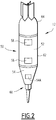
figure 2 is an external partial perspective view of a probe according to the invention; -
figure 3 is a schematic view of a probe carrier flying vehicle used in the method according to the invention ; -
figure 4 is a schematic view of a method for installing the probes according to the invention; -
figure 5 is a top view of a canopy during an additional step of a method according to the invention. - A first
ground survey assembly 10 comprising a plurality ofprobes 12 put in place by a droppingsystem 11 according to the invention is disclosed schematically infigure 1 . - The
ground survey assembly 10 is for carrying out a geophysical survey of an onshore region ofinterest 14 schematically shown infigure 1 . - The
assembly 10 is used in particular to collect geophysical data and measurements for determining the physical properties of thesubsurface 13 located in the region of interest and/or for building an image of the geology of thesubsurface 13, preferably a three-dimensional image of thesubsurface 13. - The region of
interest 14 is for example a region having anuneven terrain 16. Theuneven terrain 16 in particular comprises hills, mountains, cliffs or any type of rugged terrain. The region ofinterest 14 is for example located on foothills which are difficult to access. - The region of
interest 14 further comprisesvegetation 18. Thevegetation 18 is for example a forest, in particular a tropical forest. It comprises a high density of vegetation, forexample trees 20 forming acanopy 22 which covers a majority of the surface of the ground in the region ofinterest 14. - The
subsurface 13 located below the ground comprises layers of geological formation and potentially oil and gas reservoirs. - In the region of
interest 14, thevegetation 18 defines a plurality of natural and/orartificial clearings 24. Thevegetation 18 in the region ofinterest 14 also defines sky holes 26 in thecanopy 22. - The
clearings 24 are spread in the region ofinterest 14, at a distance generally comprised between 100 m and 500 m, preferentially around 300 m, taken along the line of sight between twoadjacent clearings 24. - The
clearings 24 generally have a surface area greater than 25 m2, at the ground level and generally greater than 900m2 at the top of thecanopy 22. Theseismic sources 30 can be put in place in theclearings 24. - A clearing 24 is for example defined in a OGP Standard "OGP-Helicopter Guideline for Land Seismic and Helirig operations - Report 420 version 1.1 June 2013
- Sky holes 26 are generally natural. They advantageously form a vertical "light tube" between the
canopy 22 and the ground. - For example, the sky holes 26 have a minimal surface area greater than 1 m2, preferentially greater than 3 m2, and comprised for example between 3 m2 and 20 m2. The
probes 12 are able to be dropped in eachsky hole 26, as will be described later. - At least a
sky hole 26 has a surface area which is smaller than the surface area of theclearings 24. - The
ground survey assembly 10 comprises a plurality ofsources 30, able to generate a geophysical stimulus in the ground, in particular a seismic signal. Theground survey assembly 10 further comprises a plurality ofprobes 12 spread in the region ofinterest 14 to collect geophysical data arising from the seismic signal generated by thesources 30. - In the example of
figure 1 , theground survey assembly 10 further comprises the droppingsystem 11 for dropping theprobes 12. The droppingsystem 11 includes a fleet of probecarrier flying vehicles 32, able to fly above thevegetation 18 to carry eachprobe 12 above its point of installation, and, for each probecarrier flying vehicle 32, a launchingunit 34 able to separate eachprobe 12 carried by the flyingvehicle 32 above the ground to let theprobe 12 free fall to its installation point in the ground. - According to the invention, the dropping
system 11 also comprises a dropping area predetermination system 35 (seefigure 1 ), to predetermine the location of a plurality of target dropping areas in the region ofinterest 14, before each probecarrier flying vehicle 32 is flown above the region ofinterest 14. The droppingsystem 11 also includes a dropping area flying detection system 37 (seefigure 3 ), to verify if each target dropping area is at the predetermined location, when the probecarrier flying vehicle 32 flies above the target dropping area. - The
ground survey assembly 10 further comprises at least a base 36 (or secondary camp), comprising at least a collection and/oranalysis unit 38 and atelecommunication system 40 able to transfer data measured by theprobes 12 to the collection and/oranalysis unit 38, and from the collection and/oranalysis unit 38 to an external station (not shown). - The base 36 advantageously comprise a helipad, night facilities for crews, and/or antenna which collect data from small antenna located in the vicinity. It is used for management of the take-off and landing . It may be used for first aid (e.g. medevac).
- The external station may be located at a main camp (not shown). The main camp advantageously comprises facilities for collecting data, as well as a main computing unit, and/or a control center.
- Advantageously, the
ground survey assembly 10 comprises at least an additional flying vehicle 42 (shown infigure 1 ) able to fly over the vegetation to carry thesources 30 in theclearings 24. - Each
seismic source 30 is able to generate a controlled seismic energy generating a geophysical stimulus, in particular a seismic signal in the ground. - The
source 30 for example comprises an explosive, in particular dynamite, able to generate the geophysical stimulus. - The
source 30 is inserted in a hole drilled into the ground, for example at a depth comprised between 0 meter and 100 meters, preferably between 5 meters and 80 meters. - In a variant, the
source 30 comprises a mechanical device such as a hammer, a vibrator. - The density of
sources 30 locations laid in the region ofinterest 14 is generally comprised between 10 source locations per km2 and 100 source locations per km2. Each source location can comprise one ormore source 30. - Each
source 30 is preferably arranged in aclearing 24. Thesource 30 is generally brought to the clearing 24 by the additional flyingvehicle 42. It can be put in place by a unmanned ground vehicle, such as a semi automatic drilling platform. - Each
probe 12 is partially introduced in the ground to sense in particular the seismic signals resulting from interactions of the seismic stimulus generated by asource 30 with the geology of thesubsurface 13. - The density of
probes 12 is comprised for example between 10 probes per km2 and 1000 probes per km2, in particular between 300 probes per km2 and 500 probes per km2, notably 400 probes per km2. - In the example shown in
figure 2 , eachprobe 12 has the shape of a dart. In a variant, theprobe 12 has the shape of a ball or a parallel pipe shape. - The
probe 12 comprises ahollow casing 50 defining a closedinner compartment 52, asensor unit 54 comprising at least asensor 54A received in the closedinner compartment 52 to sense at least a physical quantity, in particular a seismic signal. - The
probe 12 further comprises anemitter 56 able to collect and send via an antenna (not shown) data representative of the physical quantity sensed by thesensor unit 54, and at least apower source 58 able to power thesensor unit 54 and/or theemitter 56. Theemitter 56 and thepower source 58 are also received in the closedinner compartment 52 of thehollow casing 50. - In this example, the
hollow casing 50 advantageously comprise a taperedlower end 60 to penetrate the ground, acentral tubular partition 62, and arear closing part 64 mounted at the rear of thecentral partition 62 opposite from the taperedlower end 60. - The
sensor 54A comprises at least one geophone, in particular three geophones and/or an accelerometer. - The fleet of probe
carrier flying vehicle 32 comprises a plurality of probecarrier flying vehicles 32, for example between 2 and 1000 probecarrier flying vehicles 32, preferably between 10 and 100 probecarrier flying vehicles 32. - As shown in
figure 3 , each probecarrier flying vehicle 32 comprises aplatform 70 carrying the launchingunit 34 and theprobes 12, and at least apropeller 72, in this example a plurality ofpropellers 72. - Each probe
carrier flying vehicle 32 further comprises acentral control unit 74 for driving thepropellers 72 and directing the probecarrier flying vehicle 32 above the dropping area at which eachprobe 12 has to be put in place. - The probe
carrier flying vehicle 32 further comprises acommunication unit 76 for receiving guidance data from thebase 36 and for sending data to the base 36 through thetelecommunication system 40. - The
central control unit 74 is able to receive data from the base 36 regarding the trajectory and/or the target position to be reached by the probecarrier flying vehicle 32. It is for example connected to aposition detector 82 such as a ground positioning system. - The
central control unit 74 is also able to activate thepropellers 72 to fly the probecarrier flying vehicle 32 to the aimed target position along the desired trajectory. - The launching
unit 34 comprises at least aretainer 90 able to hold at least aprobe 12 in theplatform 70, and at least arelease mechanism 92 able to release theretainer 90 to free theprobe 12 from theretainer 90 and let it fall down to the dropping area. - A volume located below the
retainer 90 is advantageously open to let theprobe 12 free fall from theplatform 70. Therelease mechanism 92 is connected to thecentral control unit 74 for its actuation. It is able to release theretainer 90, without providing thrust to theprobe 12. - In a variant, the
probe 12 can be launched toward the ground. The launching impulse can be obtained by the integration of a thruster (ex: pyrotechnic, turbine, propeller...) in theprobe 12, or by the use of a propulsion mechanism onboard the probe carrier flying vehicle 32 (e.g. launching actuator or the decompression of a spring). The impulse accelerates the fall of theprobe 12 to help it penetrate further into thecanopy 22 and / or the ground. - In yet another variant, the fall of the
probe 12 can be slowed down by a braking mechanism (e.g. a parachute attached to the rear closing part 64). Slowing down the fall of theprobe 12 can for instance avoid damages to the probe. - In reference to
figure 1 , the dropping areaground predetermination system 35 comprises at least anaerial observation platform 100, able to collect information representative of the vegetation at a plurality of locations in the region ofinterest 14, and ananalyzer 102 able to analyze the vegetation information and determine locations of target dropping area and potential vegetation information at the target dropping area. - The
aerial observation platform 100 is for example a satellite, a balloon, an airship, an airplane, an unmanned aerial vehicle and/or a helicopter. Theplatform 100 is equipped with at least avegetation detector 104 able to collect data representative of the vegetation information at various locations of the region ofinterest 14. - The
aerial observation platform 100 is able to pass above the region ofinterest 14 before determining potential locations of theprobes 12 in the region ofinterest 14. - The
vegetation detector 104 is for example an optical detector. It comprises in particular an optical camera, and/or an optical sensor such as a LIDAR. - The LIDAR is able to illuminate the
vegetation 18 with a pulsed laser light and to measure the reflected pulse with a sensor. A digital representation of the region of interest can be established based on the data collected at various locations. - The data collected with the
vegetation detector 104 at a particular location depends on the vegetation type and/or density at the particular location and constitutes a vegetation information at the particular location. - The
analyzer 102 is able to analyze the vegetation information collected by thevegetation detector 104 to determine the type of vegetation and/or the density of vegetation at a particular location. - The
analyzer 102 is able to sort the vegetation information, in order to determine whether the vegetation information at a particular location is comprised in a first category of vegetation, which prevents the location to become a target dropping area, and a second category of vegetation, which allows the location to become a target dropping area. - Preferentially, the vegetation information comprises a vegetation density calculated from the data collected by
vegetation detector 104. The vegetation density in the first category of vegetation is greater than the vegetation density in the second category of vegetation. A density threshold is predefined to delimit a minimal vegetation density in the first category and a maximal vegetation density in the second category of vegetation. - Advantageously, in the second category of vegetation, the area is a clear terrain.
- The vegetation density is for example the vegetation density of a clearing 24 or of a
sky hole 26. - Additionally, or in variant, the vegetation information comprise a type of vegetation.
- The first category of vegetation comprises a first vegetation type, whereas the second category of vegetation comprises a second vegetation type.
- For example, the first vegetation type includes high canopy trees. The first vegetation may include trees with large trunks, for example having a trunk diameter at the base greater than 1 m, trees with a dense crown, for example with a crown having a diameter greater than 30 m, and/or trees with wide roots, e.g., trees having roots of transverse extent greater than 10 m.
- On the contrary, the second vegetation type includes trees with smaller trunks, smaller crowns and roots with lesser transverse extent.
- Trees of the second vegetation type for example include trees of the Arecales order such as palm trees.
- The
analyzer 102 is able to analyze the data collected by thevegetation detector 104, in particular the color and/or intensity of the collected data at a particular location in the region ofinterest 14 to determine whether the particular location has a vegetation information, in particular a vegetation density and/or a vegetation type in the first category of vegetation or in the second category of vegetation. - Advantageously, the
analyzer 102 is able to determine the locations ofclearings 24 or/and of sky holes 26, based on the vegetation information collected by thevegetation detector 104. - The location of
clearings 24 and/orskyholes 26 can be for example carried out by identifying locations of trunks, the extent of the crown from each trunk and by determining the clear areas between the crowns. - The
analyzer 102 is therefore able to map the locations potentially having a first category of vegetation preventing the dropping of a probe and the locations potentially having a second category of vegetation, which allows the dropping of a probe. - Based on the analysis made by the
analyzer 102, and based on additional geophysical and logistical parameters, a number of target dropping areas in which the vegetation is in the second category of vegetation can be predetermined. - The dropping area flying
detector system 37 comprises at least a flyingvegetation detector 110 carried by a flying platform to measure the vegetation information at the target dropping area when a probecarrier flying vehicle 35 has reached the target dropping area. The dropping area flyingdetector system 37 further comprises anactivation unit 112, advantageously located at the base 36 to control the activation of the launchingunit 34 depending on the vegetation information measured at the target dropping area using the flyingvegetation sensor 110. - In
Figure 3 , the droppingarea detecting system 37 also comprises aredirection unit 114, able to seek an alternate dropping area in a neighboring zone of the target dropping area if the vegetation at the target dropping area is not suitable for dropping theprobe 12. - As shown in
figure 3 , the flyingvegetation detector 110 is for example carried by the probecarrier flying vehicle 32, or by another flying vehicle such as unmanned safety clearance vehicle. - The flying
vegetation detector 110 is advantageously of the same type as thevegetation detector 104. Preferentially, the flyingvegetation detector 110 is an optical detector such as a laser and/or a LIDAR. Its focus direction points downwardly towards the ground from theprobe carrier vehicle 32. - The flying
vegetation detector 110 is able to send an optical signal towards the ground, and to measure the intensity and/or wavelength of the reflected signal which constitutes vegetation information. - The
activation unit 112 is able to analyze the vegetation information received from the flyingvegetation detector 110, in order to determine whether the vegetation information at the target dropping area is comprised in a first category of vegetation, which prevents the dropping of theprobe 12, or is comprised in a second category of vegetation, which allows dropping of theprobe 12. - The vegetation information may comprise a vegetation height. The vegetation height measured by the flying
vegetation detector 110 based on the reflection time of the signal. It is compared to the ground height and/or to the height of thecanopy 22 in the neighboring areas. - In a particular example, if the vegetation height measured at a particular location is close to the ground height (for example having a difference of less than 50% with the ground height), then, the vegetation information at the particular location.is in the second category of vegetation.
- On the contrary, if the vegetation height measured at a particular location is close to the canopy height of the neighboring area (for example having a difference of less than 50% with the canopy height), then the vegetation information at the particular location.is in the first category of vegetation.
- As defined above, the vegetation information may comprise a vegetation density, the vegetation density in the first category of vegetation being greater than the vegetation density in the second category of vegetation. A threshold of vegetation density can be predetermined for example by experimental measurement. Preferably, the vegetation in the second category is a
clearance 24 vegetation density or asky hole 26 vegetation density. - Additionally or in a variant, the vegetation information comprises a vegetation type, with a first category of vegetation as defined above and a second category of vegetation as defined above.
- In an embodiment; the
activation unit 112 is able to provide a clearance signal to thelaunching unit 34 if the vegetation information is in the second category of information. - In an alternate and/or complementary embodiment, the
activation unit 112 is able to prevent the activation of the launchingunit 34 if the vegetation type at the potential dropping point is in the first vegetation category. - The
activation unit 112 is preferably located on the ground. It is for example located at thebase 36. It is able to receive data from the flyingvegetation detector 104 though thetelecommunication system 40. It is able to send data to thelaunching unit 24 through thetelecommunication system 40, in particular, a clearance signal allowing the activation of the launchingunit 34 and/or a prevention signal inhibiting the activation of the launchingunit 34. - The
redirection unit 114 is able to relocate the probecarrier flying vehicle 32 in a neighboring zone around the target dropping area when the vegetation information at the target dropping area is determined to be in the first category of vegetation, in order to seek an alternate dropping area in which the vegetation information is in the second category of vegetation. - In reference to
figure 5 , theredirection unit 114 is for example able to move the probecarrier flying vehicle 32 in a neighboring zone NZ of the target dropping area TDA having a span of at most 5 m to 10 m of the original target dropping area. - The flying
vegetation detector 110 is able to be moved above the neighboring zone NZ to measure vegetation information at several locations in the neighboring zone, in order to find an alternate dropping area having a vegetation information in the second category of vegetation. - If the
redirection unit 114 does not find an alternate dropping area in the second category of vegetation, theredirection unit 114 is able to let the probecarrier flying vehicle 32 move to a further target dropping area, and/or to return to thebase 36. - In reference to
figure 1 , thetelecommunication system 40 comprises antennas located in at least part of theclearings 24, and/or flying antennas. It is able to collect data received from theemitter 56 of eachprobe 12 and to convey it to the collection andanalysis unit 38 at thebase 34. It is also able to transfer data between theactivation unit 112 at thebase 36 and thecommunication unit 76 of each probecarrier flying vehicle 32. - The additional flying
vehicle 42 is for example a helicopter an airship (ex: hybrid airship...) or a balloon which is able to carry thesources 30 towards each clearing 24. - The installation and operation of the
ground survey assembly 10 according to the invention will be now described. - Initially, the
aerial observation platform 100 is moved above the region ofinterest 14 to carry out measurements of vegetation information at various locations with thevegetation detector 104. - Preferentially, a full scan of the region of
interest 14 is carried out to determine a map of vegetation information as a function of location in the region ofinterest 14. - Then, the
analyzer 102 analyzes the vegetation information measured with thevegetation detector 104 to determine whether the vegetation information is in a first category of vegetation, which prevents the dropping ofprobes 12 and or in a second category of vegetation, which allows the dropping ofprobes 12. - As explained above, the
analyzer 102 for example analyzes the intensity and/or wavelength of the measured signal, to determine a vegetation density at each measured location. - Based on a predetermined threshold, the
analyzer 102 sorts whether the vegetation density is in a first category of vegetation, or in the second category of vegetation. - In particular, the
analyzer 102 determines whether the vegetation density corresponds to aclearing 24, and/or to asky hole 26. - In a variant, or in complement, based on the wavelength and intensity of the measured signal, and on a correlation table, the
analyzer 102 analyzes a vegetation type and sorts among a first vegetation type corresponding to a first category of vegetation and a second vegetation type corresponding to a second category of vegetation. - For example, the first vegetation type includes high canopy trees. The second vegetation type includes trees of the Arecales order.
- Based on the mapping of the vegetation information as a function of location, a preliminary survey of potential vegetation information at each location of the region of
interest 14 is established, to allow the definition of target dropping areas for theprobes 12, using other parameters such as geophysical parameters and/or logistical parameters. - Once a plurality of target dropping areas have been defined, each probe
carrier flying vehicle 32 is flown from the base 36 to a target dropping area. - The flying
vegetation detector 110 is then activated to measure an actual vegetation information at the target dropping area. Theactivation unit 112 receives the vegetation information, and determines whether the vegetation information measured at the target dropping area is comprised in a first category of vegetation preventing the activation of the launchingunit 34 or in a second category of vegetation allowing the activation of the launchingunit 34, as defined above. - In an embodiment, the
activation unit 112 provides a clearance signal to thelaunching unit 34 only if the vegetation information measured by the flyingvegetation detector 110 at the target dropping area is in the second category of vegetation. - The clearance signal is then transmitted to the
central control unit 74 of the probecarrier flying vehicle 32 through thetelecommunication system 40 and throughcommunication unit 76. - The
central control unit 74 then activates therelease mechanism 92 to free theprobe 12 from theretainer 90. Theprobe 12 falls down from theretainer 90 to the ground, and penetrates at least partially into the ground to establish coupling between thesensor unit 54 and the ground. - In a variant or in complement, the
activation unit 112 sends a prevention signal to thelaunching unit 34, preventing the activation of the launchingunit 34 if the vegetation information measured by the flyingvegetation detector 110 at the target dropping area is in the first category of vegetation. - If the
activation unit 112 determines that the vegetation information is in the first category of vegetation, theredirection unit 114 modifies the position of the probecarrier flying vehicle 32, to scan a neighboring zone NZ around the target dropping area TDA with the flyingvegetation detector 110. - The span of the neighboring zone NZ is at most 5 m to 10 m from the target dropping area TDA. The flying
vegetation detector 110 is activated to carry out measurements of vegetation information at various locations in the neighboring zone NZ, and to send it to theactivation unit 112. - If the
activation unit 112 determines that the information vegetation at an alternate dropping area in the neighboring zone NZ is in the second category, it provides a clearance signal to thelaunching unit 34 which carries out the launch of theprobe 12 as described above. - On the contrary, if no alternate dropping area having a vegetation in the second category of vegetation is found in the neighboring zone NZ, the
redirection unit 114 lets the probecarrier flying vehicle 32 move to a further target dropping area and/or to thebase 36. - Thanks to the method according to the invention, a plurality of target dropping area for the
probes 12 can be easily defined based on an initial determination of vegetation information at a plurality of locations in the region ofinterest 14. Then, when each probecarrier flying vehicle 32 flies to a target dropping area, the flyingvegetation detector 110 is able to verify the vegetation information at the target dropping area, to confirm that the type of vegetation present at the target dropping area is compatible with the launching of aprobe 12. - This greatly increases the chances for the
probe 12 to be successfully launched and coupled to the ground without significant interference with thevegetation 18. - The plurality of
probes 12 are then preferentially launched in artificial ornatural clearings 24 of the region ofinterest 14 and into sky holes 26 of the region ofinterest 14. - In case the vegetation information actually measured at the target dropping area just before launching the
probe 12 is not consistent with the initial measurement carried out before defining the positions of the target dropping areas, a neighboring zone NZ around the target dropping area is advantageously scanned to determine if an alternate dropping area can be found. This increases the productivity of the dropping method by avoiding an unnecessary return to thebase 36. - In a variant shown in dotted lines in
figure 4 , the flyingvegetation detector 110 is carried by anadditional flying vehicle 120, distinct form the probecarrier flying vehicles 32. Theadditional flying vehicle 120 is devoid of launchingunit 34. It advantageously flies above the probecarrier flying vehicle 32. - In a variant in which the
probe 12 is equipped with an accelerometer, the coupling of eachprobe 12 is assessed based on a measurement of the vertical acceleration versus time of theprobe 12 from its launching to its impact. - The fall of the
probe 12 is then advantageously monitored to determine whether it was direct to the ground or whether it was hindered, based of variations of the signal of the accelerometer during the fall. - The duration of flight is also calculated by determining the time of release and the time of impact. Knowing the fall height, the velocity at impact can be calculated.
- Other parameters such as duration of impact, maximum deceleration, potential rebound can also be evaluated from the variation and intensity of the accelerometer signal versus time at impact.
- In a variant, the
probes 12 are put in place by landing the probecarrier flying vehicle 32 at the dropping area. The launchingunit 34 is activated when the probecarrier flying vehicle 32 has landed. The launchingunit 34 advantageously comprises a tool to at least partially insert theprobe 12 in the ground, for example by drilling. - When the probe
carrier flying vehicle 32 is located above a target dropping area, before landing the probecarrier flying vehicle 32 and before activating the launchingunit 34, vegetation information at the target dropping area is obtained using a flyingvegetation detector 110, as described above. - In other variations, the
probe 12 is partially or totally recovered at the end of the survey. - In an embodiment, the
probe 12 is equipped with a recovery member, such as a hook or a ring on its upper part. A recovery flying vehicle, such as an unmanned aerial vehicle as described above, flies above theprobe 12 and picks up theprobe 12 using the recovery member. - The pickup of the
probe 12 can be total or partial, depending on the force available in the recovery flying vehicle. In the latter case, the part of theprobe 12 remaining in the ground is advantageously biodegradable (such as disclosed e.g. inEP3080642 ). - In another embodiment, the
probe 12 is dropped from above thecanopy 22 with a link, such as a wire or a cable, connected to it, the free end of the link remaining at the top of thecanopy 22 to be picked up by the recovery flying vehicle. - The link is advantageously equipped with a recovery member at its free end (for example a balloon inflated with lighter than air gas). Advantageously, the link may constitute or bear an antenna connected to the
emitter 56. - Just as before, the pickup of the
probe 12 is total or partial. - In a variant or in addition, the
system 11 comprises at least a flying ground surface detector, theactivation unit 112 being able to determine a ground surface information at a target dropping area of theprobe 12 using the ground surface vegetation detector when the probecarrier flying vehicle 32 is located above a target dropping area before activating the launchingunit 34. - Advantageously, the
activation unit 112 is able to prevent activation of the launchingunit 34 when the ground surface information at the target dropping area is comprised in a first category of ground surface and/or is able to allow activation of the launchingunit 34 when the ground surface information at the target dropping area is comprised in a second category of ground surface. - The first category of ground surface comprises locations comprising at least a physical obstacle on the ground preventing the adequate coupling of the
probe 12 in the ground. The physical obstacle can be for example a large rock, a large tree, a construction, in particular a building, a vehicle, etc ... - On the contrary, the second category of ground surface comprises locations without physical obstacle on the ground, these locations allowing the adequate coupling of the
probe 12 in the ground. The second category of locations comprise for example open fields, clearings, open holes, etc - The flying ground surface detector is for example an optical or hyperspectral camera, a LIDAR..... It is able to analyze the nature of the ground surface and/or the size of elements detected on the ground surface for example by image or LIDAR data analysis, and / or automatic pattern and form recognition to sort whether the detected ground surface belongs to the first category of ground surface or to the second category of ground surface. Automatic pattern and form recognition can be performed by techniques known in the art such as machine learning to train a machine to recognize objects (for instance boulders, buildings, vehicles...)
- Preferentially, the flying ground surface detector is carried by the probe
carrier flying vehicle 32. - Advantageously, as described above for the
vegetation detector 110, thesystem 11 comprises aredirection unit 114, able to seek an alternate dropping area in a neighboring zone NZ of the target dropping area TDA if the ground surface at the target dropping area TDA is in the second category of ground surface, a span of the neighboring zone being preferably at most 5 m to 10 m from the target dropping area TDA where the ground surface information is in the first category of ground surface.
Claims (16)
- A method of dropping a plurality of probes (12) intended to partially penetrate into a ground, to carry out measurements in the ground, the method comprising the following steps:- flying at least a probe carrier flying vehicle (32) above a dropping area on the ground, the probe carrier flying vehicle (32) carrying probes (12) and a launching unit (34), able to separate each probe (12) from the probe carrier flying vehicle (32) ;- activating the launching unit (34) to separate at least one of the probes (12) from the probe carrier flying vehicle (32);- at least partial insertion of the probe (12) in the ground of the dropping area ; characterized by:- when the probe carrier flying vehicle (32) is located above a target dropping area, before activating the launching unit (34), determining a vegetation information at the target dropping area using a flying vegetation detector (110) or/and determining a ground surface information at the target dropping area using a flying ground surface detector.
- A method according to claim 1, wherein the activation of the launching unit (34) to separate at least one of the probes (12) from the probe carrier flying vehicle (32) is done when the probe carrier flying vehicle (32) is flying above the dropping area;
the method comprising the falling of the probe (12) from the probe carrier flying vehicle (32) in the ground of the dropping area. - The method according to claim 1 or 2 wherein the flying vegetation detector (110) is carried by the probe carrier flying vehicle (32) or/and the flying ground surface detector being carried by the probe carrier flying vehicle (32).
- The method according to any one of claims 1 to 3, comprising preventing the activation of the launching unit (34) when the vegetation information at the target dropping area is comprised in a first category of vegetation and/or allowing the activation of the launching unit (34) when the vegetation information at the target dropping area is comprised in a second category of vegetation or/and
preventing the activation of the launching unit (34) when the ground surface information at the target dropping area is comprised in a first category of ground surface and/or allowing the activation of the launching unit (34) when the ground surface information at the target dropping area is comprised in a second category of ground surface,
the vegetation information advantageously comprising a vegetation height. - The method according to claim 4, wherein the vegetation information comprises a vegetation density, the vegetation density in the first category of vegetation being greater than the vegetation density in the second category of vegetation,
the vegetation density in the second category advantageously being a clear terrain density or a sky hole vegetation density. - The method according to any one of claims 4 to 5, wherein the vegetation information comprises a vegetation type, the first category of vegetation comprising a first vegetation type, the second category of vegetation comprising a second vegetation type,
the first vegetation type advantageously including high canopy trees, trees with large trunks, dense crown and/or wide roots, the second vegetation type advantageously including trees of the Arecales order. - The method according to any one of claims 4 to 6, comprising, when the vegetation information at the target dropping area is comprised in the first category of vegetation, seeking an alternate dropping area having a vegetation information in the second category of vegetation, in a neighboring zone of the target dropping area where the vegetation information is in the first category of vegetation or/and
when the ground surface information at the target dropping area is comprised in the first category of ground surface, seeking an alternate dropping area having a ground surface information in the second category of ground surface, in a neighboring zone of the target dropping area where the ground surface information is in the first category of ground surface,
a span of the neighboring zone being advantageously at most 5 m to 10 m from the target dropping area where the vegetation density information is in the first category of vegetation. - The method according to claim 7, wherein seeking an alternate dropping area comprises moving the flying vegetation detector (110) above the neighboring zone to measure vegetation information at several locations in the neighboring zone, in order to find an alternate dropping area having a vegetation information in the second category of vegetation or/and
seeking an alternate dropping area comprises moving the ground surface detector above the neighboring zone to measure ground surface information at several locations in the neighboring zone, in order to find an alternate dropping area having a ground surface information in the second category of ground surface. - The method according to any one of the preceding claims, comprising, before flying the probe carrier flying vehicle (32) to the target dropping area, obtaining a preliminary survey of potential vegetation information in a region of interest (14) by at least an aerial platform (100) distinct from the or each probe carrier flying vehicle (32), and defining at least a target dropping area where the potential vegetation is in the second category based on the survey of potential vegetation information and/or comprising, before flying the probe carrier flying vehicle (32) to the target dropping area, obtaining a preliminary survey of potential ground surface information in a region of interest (14) by at least an aerial platform (100) distinct from the or each probe carrier flying vehicle (32), and defining at least a target dropping area where the potential ground surface is in the second category based on the survey of potential ground surface information,
the aerial platform (100) being advantageously a satellite, a balloon, an airship, an airplane, an unmanned aerial vehicle and/or a helicopter. - The method according to any one of the preceding claims, wherein the flying vegetation detector (110) and/or the ground surface detector comprises an electromagnetic sensor, in particular an optical sensor, the sensor being advantageously a LIDAR.
- A system (11) for dropping a plurality of probes (12) intended to partially penetrate into a ground, to carry out measurements in the ground, comprising:- at least a probe carrier flying vehicle (32) intended to fly above a dropping area on the ground, the probe carrier flying vehicle (32) carrying probes (12) and a launching unit (34), able to separate each probe (10) from the probe carrier flying vehicle (32);- an activation unit (112) able to activate the launching unit (34) to separate at least one of the probes (12) from the probe carrier flying vehicle (32) ;characterized by :- at least a flying vegetation detector (110), the activation unit (112) being able to determine a vegetation information at a target dropping area of the probe (12) using the flying vegetation detector (110) when the probe carrier flying vehicle (32) is located above a target dropping area before activating the launching unit (34) and/or- at least a ground surface detector (110), the activation unit (112) being able to determine a ground surface information at a target dropping area of the probe (12) using the ground surface detector when the probe carrier flying vehicle (32) is located above a target dropping area before activating the launching unit (34).
- The system (11) according to claim 11, wherein the activation unit (112) is able to activate the launching unit (34) to separate at least one of the probes (12) from the probe carrier flying vehicle (32) when the probe carrier flying vehicle (32) is flying above the dropping area and to let the probe (12) fall from the probe carrier flying vehicle (32) in the ground of the dropping area.
- The system according to claim 12, wherein the probe carrier flying vehicle (32) carries the flying vegetation detector (110) and/or the flying ground surface detector.
- The system according to any one of claims 11 to 13, wherein the activation unit (112) is able to prevent activation of the launching unit (34) when the vegetation information at the target dropping area is comprised in a first category of vegetation and/or is able to allow activation of the launching unit (34) when the vegetation information at the target dropping area is comprised in a second category of vegetation
and/or the activation unit (112) is able to prevent activation of the launching unit (34) when the ground surface information at the target dropping area is comprised in a first category of ground surface and/or is able to allow activation of the launching unit (34) when the ground surface information at the target dropping area is comprised in a second category of ground surface. - The system according to any one of claims 11 to 14, comprising a redirection unit (114), able to seek an alternate dropping area in a neighboring zone of the target dropping area if the vegetation at the target dropping area is in the second category of vegetation, a span of the neighboring zone being preferably at most 5 m to 10 m from the target dropping area where the vegetation information is in the first category of vegetation, and/or
comprising a redirection unit (114), able to seek an alternate dropping area in a neighboring zone of the target dropping area if the ground surface at the target dropping area is in the second category of ground surface, a span of the neighboring zone being preferably at most 5 m to 10 m from the target dropping area where the ground surface information is in the first category of ground surface. - The system according to any one of claims 11 to 15, wherein the flying vegetation detector (110) comprises an electromagnetic sensor, in particular an optical sensor.
Applications Claiming Priority (1)
| Application Number | Priority Date | Filing Date | Title |
|---|---|---|---|
| EP17305687 | 2017-06-08 |
Publications (2)
| Publication Number | Publication Date |
|---|---|
| EP3413096A1 true EP3413096A1 (en) | 2018-12-12 |
| EP3413096B1 EP3413096B1 (en) | 2022-11-30 |
Family
ID=59077982
Family Applications (1)
| Application Number | Title | Priority Date | Filing Date |
|---|---|---|---|
| EP18176442.4A Active EP3413096B1 (en) | 2017-06-08 | 2018-06-07 | A method of dropping a plurality of probes intended to partially penetrate into a ground using a vegetation detection, and related system |
Country Status (3)
| Country | Link |
|---|---|
| US (1) | US11061155B2 (en) |
| EP (1) | EP3413096B1 (en) |
| CN (1) | CN109143321B (en) |
Families Citing this family (7)
| Publication number | Priority date | Publication date | Assignee | Title |
|---|---|---|---|---|
| CN110009146B (en) * | 2019-03-29 | 2021-08-24 | 西南交通大学 | A planning method for tree barrier felling in transmission lines based on hyperspectral remote sensing technology |
| US11238283B2 (en) | 2019-10-04 | 2022-02-01 | The Climate Corporation | Hybrid vision system for crop land navigation |
| CN110697042B (en) * | 2019-10-18 | 2020-07-10 | 中国地质大学(北京) | Seismic exploration system based on unmanned aerial vehicle puts in seismic source |
| CN112537450B (en) * | 2019-10-18 | 2022-05-24 | 中国地质大学(北京) | Seismic source releasing device based on unmanned aerial vehicle |
| US11483960B2 (en) * | 2019-11-19 | 2022-11-01 | Cnh Industrial Canada, Ltd. | System and method for monitoring seedbed conditions using a seedbed sensing assembly supported on a UAV |
| US11713117B2 (en) | 2020-03-31 | 2023-08-01 | Cnh Industrial America Llc | System and method for anchoring unmanned aerial vehicles to surfaces |
| CN115616654B (en) * | 2022-10-09 | 2023-11-03 | 中国地质大学(北京) | Seismic source excitation device and control method |
Citations (5)
| Publication number | Priority date | Publication date | Assignee | Title |
|---|---|---|---|---|
| EP1903297A2 (en) * | 2006-09-21 | 2008-03-26 | Honeywell International, Inc. | Unmanned sensor placement in a cluttered terrain |
| EP2741264A1 (en) * | 2012-12-07 | 2014-06-11 | The Boeing Company | Forest sensor deployment and monitoring system |
| US20150053480A1 (en) | 2013-08-22 | 2015-02-26 | Elwha Llc | Kinetic penetrator beacons for multistatic geophysical sensing |
| WO2015085155A1 (en) * | 2013-12-06 | 2015-06-11 | Westerngeco Llc | Positioning survey sensors using an airborne vehicle |
| CA2927529A1 (en) * | 2015-03-02 | 2016-08-22 | Cgg Services Sa | System and method for coupling a seismic sensor to the ground |
Family Cites Families (37)
| Publication number | Priority date | Publication date | Assignee | Title |
|---|---|---|---|---|
| US5621460A (en) * | 1994-10-11 | 1997-04-15 | Lockheed Martin Corporation | Optical differentiation between plants and background utilizing a single CCD camera |
| US6160902A (en) * | 1997-10-10 | 2000-12-12 | Case Corporation | Method for monitoring nitrogen status using a multi-spectral imaging system |
| US9489671B2 (en) | 2002-10-01 | 2016-11-08 | Andrew H B Zhou | Systems and methods for mobile application, wearable application, transactional messaging, calling, digital multimedia capture and payment transactions |
| US9208505B1 (en) | 2002-10-01 | 2015-12-08 | Tiger T G Zhou | Systems and methods for providing compensation, rebate, cashback, and reward for using mobile and wearable payment services |
| US20160286128A1 (en) | 2002-10-01 | 2016-09-29 | Dylan TX ZHOU | Amphibious vtol super drone camera in a mobile case (phone case) with multiple aerial and aquatic flight modes for capturing panoramic virtual reality views, selfie and interactive video |
| ES2368311B1 (en) * | 2003-07-23 | 2012-09-24 | C.I.T. Controlled Irrigation Technologies Ltd. | ADAPTIVE IRRIGATION TO VEGETATION. |
| US7954758B2 (en) | 2006-08-24 | 2011-06-07 | Aerovel Corporation | Method and apparatus for retrieving a hovering aircraft |
| JP5224906B2 (en) * | 2008-05-23 | 2013-07-03 | 株式会社Ihi | Vegetation detection apparatus and method |
| US8488874B2 (en) | 2011-01-31 | 2013-07-16 | Dalhouse University | Variable rate sprayer system and method of variably applying agrochemicals |
| US9086484B2 (en) * | 2011-06-30 | 2015-07-21 | The Boeing Company | Context-based target recognition |
| US9117185B2 (en) * | 2012-09-19 | 2015-08-25 | The Boeing Company | Forestry management system |
| US9198363B2 (en) * | 2012-12-12 | 2015-12-01 | The Boeing Company | Tree metrology system |
| US20140316614A1 (en) | 2012-12-17 | 2014-10-23 | David L. Newman | Drone for collecting images and system for categorizing image data |
| US20170073070A1 (en) | 2013-02-06 | 2017-03-16 | Zhou Tian Xing | Amphibious vertical takeoff and landing unmanned device with artificial intelligence (AI) and method and system for managing a crisis environment and controlling one or more targets |
| US20140312165A1 (en) | 2013-03-15 | 2014-10-23 | Armen Mkrtchyan | Methods, apparatus and systems for aerial assessment of ground surfaces |
| US20140263822A1 (en) | 2013-03-18 | 2014-09-18 | Chester Charles Malveaux | Vertical take off and landing autonomous/semiautonomous/remote controlled aerial agricultural sensor platform |
| CN103438869B (en) | 2013-08-28 | 2015-08-12 | 中国水利水电科学研究院 | A kind of large scale vegetation coverage aviation Dynamic Acquisition system |
| US20150130936A1 (en) | 2013-11-08 | 2015-05-14 | Dow Agrosciences Llc | Crop monitoring system |
| WO2015077452A1 (en) | 2013-11-20 | 2015-05-28 | Rowbot Systems Llc | Robotic platform and method for performing multiple functions in agricultural systems |
| US9336584B2 (en) | 2014-06-30 | 2016-05-10 | Trimble Navigation Limited | Active imaging systems for plant growth monitoring |
| US9922405B2 (en) | 2014-08-22 | 2018-03-20 | The Climate Corporation | Methods for agronomic and agricultural monitoring using unmanned aerial systems |
| US9618934B2 (en) | 2014-09-12 | 2017-04-11 | 4D Tech Solutions, Inc. | Unmanned aerial vehicle 3D mapping system |
| KR101606516B1 (en) | 2015-03-31 | 2016-03-28 | 국민대학교산학협력단 | system and method for analyzing woody growth using UAV image |
| US9468152B1 (en) | 2015-06-09 | 2016-10-18 | Harvest Moon Automation Inc. | Plant pruning and husbandry |
| JP6326009B2 (en) | 2015-06-29 | 2018-05-16 | 株式会社オプティム | Wireless aircraft, position information output method, and wireless aircraft program. |
| FR3038482B1 (en) | 2015-06-30 | 2017-08-11 | Parrot | CAMERA BLOCK CAPABLE OF INBOARDING A DRONE FOR MAPPING A FIELD AND METHOD OF MANAGING IMAGE CAPTURE BY A CAMERA BLOCK |
| CA2952098A1 (en) | 2015-12-18 | 2017-06-18 | Wal-Mart Stores, Inc. | Apparatus and method for surveying premises of a customer |
| KR101762809B1 (en) | 2016-01-21 | 2017-07-28 | 전주비전대학교산학협력단 | Method for generating topographical data for landslide prediction by using drone and selecting landslide harzard zone by using the topographical data |
| CA3016562C (en) | 2016-03-02 | 2023-09-05 | BRYX, Inc. | Method, apparatus, and computer-readable medium for gathering information |
| US10577081B2 (en) | 2016-03-24 | 2020-03-03 | Intel Corporation | Proactive vehicle control systems and methods |
| US10028452B2 (en) | 2016-04-04 | 2018-07-24 | Beesprout, Llc | Horticultural monitoring system |
| CN205589485U (en) | 2016-05-12 | 2016-09-21 | 江西兴航智控航空工业有限公司 | Novel but unmanned aerial vehicle that sprays insecticide that intellectual detection system reported to police |
| KR101759130B1 (en) | 2016-07-14 | 2017-08-01 | 주식회사 공간정보 | System For Crop Database Using Unmanned Aerial Vehicle |
| WO2018071727A1 (en) * | 2016-10-12 | 2018-04-19 | Aker Technologies, Inc. | System for monitoring crops and soil conditions |
| CN106485229A (en) | 2016-10-14 | 2017-03-08 | 黑龙江科技大学 | Agricultural ecotone remote sensing monitoring and early warning fire system |
| CN106600434B (en) | 2016-10-18 | 2021-04-23 | 河南省农业科学院农业经济与信息研究所 | Remote sensing monitoring method of crop growth based on crop model and assimilation technology |
| CN106915462A (en) | 2017-02-14 | 2017-07-04 | 福建兴宇信息科技有限公司 | Forestry pests & diseases intelligent identifying system based on multi-source image information |
-
2018
- 2018-06-06 US US16/000,989 patent/US11061155B2/en active Active
- 2018-06-07 CN CN201810582676.4A patent/CN109143321B/en active Active
- 2018-06-07 EP EP18176442.4A patent/EP3413096B1/en active Active
Patent Citations (6)
| Publication number | Priority date | Publication date | Assignee | Title |
|---|---|---|---|---|
| EP1903297A2 (en) * | 2006-09-21 | 2008-03-26 | Honeywell International, Inc. | Unmanned sensor placement in a cluttered terrain |
| EP2741264A1 (en) * | 2012-12-07 | 2014-06-11 | The Boeing Company | Forest sensor deployment and monitoring system |
| US20150053480A1 (en) | 2013-08-22 | 2015-02-26 | Elwha Llc | Kinetic penetrator beacons for multistatic geophysical sensing |
| WO2015085155A1 (en) * | 2013-12-06 | 2015-06-11 | Westerngeco Llc | Positioning survey sensors using an airborne vehicle |
| CA2927529A1 (en) * | 2015-03-02 | 2016-08-22 | Cgg Services Sa | System and method for coupling a seismic sensor to the ground |
| EP3080642A1 (en) | 2015-03-02 | 2016-10-19 | CGG Services SA | System and method for coupling a seismic sensor to the ground |
Non-Patent Citations (1)
| Title |
|---|
| OGP-HELICOPTER GUIDELINE FOR LAND SEISMIC AND HELIRIG OPERATIONS - REPORT 420, 1 June 2013 (2013-06-01) |
Also Published As
| Publication number | Publication date |
|---|---|
| CN109143321B (en) | 2021-11-09 |
| US11061155B2 (en) | 2021-07-13 |
| CN109143321A (en) | 2019-01-04 |
| EP3413096B1 (en) | 2022-11-30 |
| US20180356545A1 (en) | 2018-12-13 |
Similar Documents
| Publication | Publication Date | Title |
|---|---|---|
| EP3413096B1 (en) | A method of dropping a plurality of probes intended to partially penetrate into a ground using a vegetation detection, and related system | |
| EP3413093B1 (en) | A method of preparing and/or carrying out a ground survey in a region of interest and related apparatus | |
| US20240294254A1 (en) | Device and method for blasting avalanches | |
| US9726006B2 (en) | Kinetic penetrator beacons for multistatic geophysical sensing | |
| EP3080642B1 (en) | System and method for coupling a seismic sensor to the ground | |
| US9562396B2 (en) | Kinetic penetrator with a retrieval tether | |
| EP3635443A1 (en) | A probe intended to be partially introduced into a ground from a flying vehicle, related assembly and method | |
| US8656760B2 (en) | Impact penetrometer systems for characterizing soil properties | |
| US12122514B2 (en) | Airborne platform comprising an electrical charging system, related assemblies and methods | |
| CN111899476A (en) | Geological disaster early warning sensor for self-organized network self-built coordinates by utilizing rocket spreading | |
| JP4222512B2 (en) | Towed aerial exploration equipment | |
| EP3635441B1 (en) | A method for acquiring a seismic dataset over a region of interest | |
| US3474405A (en) | Method and apparatus for detecting the presence of enemy personnel in subterranean chambers | |
| US20220214465A1 (en) | Tool for recovering a seismic apparatus at least partially inserted in the ground, related assembly and method | |
| US20240329263A1 (en) | Sensor device for geophysical measurement intended to be disposed on a surface of a ground, related assembly and method for deploying and retrieving such a sensor | |
| WO2020115519A1 (en) | A probe intended to be partially introduced into a ground from a flying vehicle, related assembly and method | |
| Whaley | DARTs and drones: the future of onshore seismic | |
| Dannemann Dugick et al. | Initial Results from the HummingLobo Multi-Modal Ground Truth Experimental Campaigns | |
| Lahti et al. | Airborne Magnetometer Survey Update at the Massachusetts Military Reservation | |
| CN119247452A (en) | A device and method for detecting underground works based on seismic reflection waves | |
| UA154105U (en) | THE METHOD OF CONDUCTING AERIAL RECONNAISSANCE LOCATION OF MINES |
Legal Events
| Date | Code | Title | Description |
|---|---|---|---|
| PUAI | Public reference made under article 153(3) epc to a published international application that has entered the european phase |
Free format text: ORIGINAL CODE: 0009012 |
|
| STAA | Information on the status of an ep patent application or granted ep patent |
Free format text: STATUS: REQUEST FOR EXAMINATION WAS MADE |
|
| 17P | Request for examination filed |
Effective date: 20180607 |
|
| AK | Designated contracting states |
Kind code of ref document: A1 Designated state(s): AL AT BE BG CH CY CZ DE DK EE ES FI FR GB GR HR HU IE IS IT LI LT LU LV MC MK MT NL NO PL PT RO RS SE SI SK SM TR |
|
| AX | Request for extension of the european patent |
Extension state: BA ME |
|
| STAA | Information on the status of an ep patent application or granted ep patent |
Free format text: STATUS: EXAMINATION IS IN PROGRESS |
|
| 17Q | First examination report despatched |
Effective date: 20200814 |
|
| RAP1 | Party data changed (applicant data changed or rights of an application transferred) |
Owner name: TOTAL SE |
|
| GRAP | Despatch of communication of intention to grant a patent |
Free format text: ORIGINAL CODE: EPIDOSNIGR1 |
|
| STAA | Information on the status of an ep patent application or granted ep patent |
Free format text: STATUS: GRANT OF PATENT IS INTENDED |
|
| RAP1 | Party data changed (applicant data changed or rights of an application transferred) |
Owner name: TOTALENERGIES ONETECH |
|
| INTG | Intention to grant announced |
Effective date: 20220620 |
|
| GRAS | Grant fee paid |
Free format text: ORIGINAL CODE: EPIDOSNIGR3 |
|
| GRAA | (expected) grant |
Free format text: ORIGINAL CODE: 0009210 |
|
| STAA | Information on the status of an ep patent application or granted ep patent |
Free format text: STATUS: THE PATENT HAS BEEN GRANTED |
|
| AK | Designated contracting states |
Kind code of ref document: B1 Designated state(s): AL AT BE BG CH CY CZ DE DK EE ES FI FR GB GR HR HU IE IS IT LI LT LU LV MC MK MT NL NO PL PT RO RS SE SI SK SM TR |
|
| REG | Reference to a national code |
Ref country code: CH Ref legal event code: EP Ref country code: GB Ref legal event code: FG4D |
|
| REG | Reference to a national code |
Ref country code: AT Ref legal event code: REF Ref document number: 1535078 Country of ref document: AT Kind code of ref document: T Effective date: 20221215 Ref country code: DE Ref legal event code: R096 Ref document number: 602018043542 Country of ref document: DE |
|
| REG | Reference to a national code |
Ref country code: IE Ref legal event code: FG4D |
|
| REG | Reference to a national code |
Ref country code: DK Ref legal event code: T3 Effective date: 20221222 |
|
| REG | Reference to a national code |
Ref country code: NL Ref legal event code: FP |
|
| REG | Reference to a national code |
Ref country code: NO Ref legal event code: T2 Effective date: 20221130 |
|
| REG | Reference to a national code |
Ref country code: LT Ref legal event code: MG9D |
|
| PG25 | Lapsed in a contracting state [announced via postgrant information from national office to epo] |
Ref country code: SE Free format text: LAPSE BECAUSE OF FAILURE TO SUBMIT A TRANSLATION OF THE DESCRIPTION OR TO PAY THE FEE WITHIN THE PRESCRIBED TIME-LIMIT Effective date: 20221130 Ref country code: PT Free format text: LAPSE BECAUSE OF FAILURE TO SUBMIT A TRANSLATION OF THE DESCRIPTION OR TO PAY THE FEE WITHIN THE PRESCRIBED TIME-LIMIT Effective date: 20230331 Ref country code: LT Free format text: LAPSE BECAUSE OF FAILURE TO SUBMIT A TRANSLATION OF THE DESCRIPTION OR TO PAY THE FEE WITHIN THE PRESCRIBED TIME-LIMIT Effective date: 20221130 Ref country code: FI Free format text: LAPSE BECAUSE OF FAILURE TO SUBMIT A TRANSLATION OF THE DESCRIPTION OR TO PAY THE FEE WITHIN THE PRESCRIBED TIME-LIMIT Effective date: 20221130 Ref country code: ES Free format text: LAPSE BECAUSE OF FAILURE TO SUBMIT A TRANSLATION OF THE DESCRIPTION OR TO PAY THE FEE WITHIN THE PRESCRIBED TIME-LIMIT Effective date: 20221130 |
|
| REG | Reference to a national code |
Ref country code: AT Ref legal event code: MK05 Ref document number: 1535078 Country of ref document: AT Kind code of ref document: T Effective date: 20221130 |
|
| PG25 | Lapsed in a contracting state [announced via postgrant information from national office to epo] |
Ref country code: RS Free format text: LAPSE BECAUSE OF FAILURE TO SUBMIT A TRANSLATION OF THE DESCRIPTION OR TO PAY THE FEE WITHIN THE PRESCRIBED TIME-LIMIT Effective date: 20221130 Ref country code: PL Free format text: LAPSE BECAUSE OF FAILURE TO SUBMIT A TRANSLATION OF THE DESCRIPTION OR TO PAY THE FEE WITHIN THE PRESCRIBED TIME-LIMIT Effective date: 20221130 Ref country code: LV Free format text: LAPSE BECAUSE OF FAILURE TO SUBMIT A TRANSLATION OF THE DESCRIPTION OR TO PAY THE FEE WITHIN THE PRESCRIBED TIME-LIMIT Effective date: 20221130 Ref country code: IS Free format text: LAPSE BECAUSE OF FAILURE TO SUBMIT A TRANSLATION OF THE DESCRIPTION OR TO PAY THE FEE WITHIN THE PRESCRIBED TIME-LIMIT Effective date: 20230330 Ref country code: HR Free format text: LAPSE BECAUSE OF FAILURE TO SUBMIT A TRANSLATION OF THE DESCRIPTION OR TO PAY THE FEE WITHIN THE PRESCRIBED TIME-LIMIT Effective date: 20221130 Ref country code: GR Free format text: LAPSE BECAUSE OF FAILURE TO SUBMIT A TRANSLATION OF THE DESCRIPTION OR TO PAY THE FEE WITHIN THE PRESCRIBED TIME-LIMIT Effective date: 20230301 |
|
| P01 | Opt-out of the competence of the unified patent court (upc) registered |
Effective date: 20230419 |
|
| PG25 | Lapsed in a contracting state [announced via postgrant information from national office to epo] |
Ref country code: SM Free format text: LAPSE BECAUSE OF FAILURE TO SUBMIT A TRANSLATION OF THE DESCRIPTION OR TO PAY THE FEE WITHIN THE PRESCRIBED TIME-LIMIT Effective date: 20221130 Ref country code: RO Free format text: LAPSE BECAUSE OF FAILURE TO SUBMIT A TRANSLATION OF THE DESCRIPTION OR TO PAY THE FEE WITHIN THE PRESCRIBED TIME-LIMIT Effective date: 20221130 Ref country code: EE Free format text: LAPSE BECAUSE OF FAILURE TO SUBMIT A TRANSLATION OF THE DESCRIPTION OR TO PAY THE FEE WITHIN THE PRESCRIBED TIME-LIMIT Effective date: 20221130 Ref country code: CZ Free format text: LAPSE BECAUSE OF FAILURE TO SUBMIT A TRANSLATION OF THE DESCRIPTION OR TO PAY THE FEE WITHIN THE PRESCRIBED TIME-LIMIT Effective date: 20221130 Ref country code: AT Free format text: LAPSE BECAUSE OF FAILURE TO SUBMIT A TRANSLATION OF THE DESCRIPTION OR TO PAY THE FEE WITHIN THE PRESCRIBED TIME-LIMIT Effective date: 20221130 |
|
| PG25 | Lapsed in a contracting state [announced via postgrant information from national office to epo] |
Ref country code: SK Free format text: LAPSE BECAUSE OF FAILURE TO SUBMIT A TRANSLATION OF THE DESCRIPTION OR TO PAY THE FEE WITHIN THE PRESCRIBED TIME-LIMIT Effective date: 20221130 Ref country code: AL Free format text: LAPSE BECAUSE OF FAILURE TO SUBMIT A TRANSLATION OF THE DESCRIPTION OR TO PAY THE FEE WITHIN THE PRESCRIBED TIME-LIMIT Effective date: 20221130 |
|
| REG | Reference to a national code |
Ref country code: DE Ref legal event code: R097 Ref document number: 602018043542 Country of ref document: DE |
|
| PLBE | No opposition filed within time limit |
Free format text: ORIGINAL CODE: 0009261 |
|
| STAA | Information on the status of an ep patent application or granted ep patent |
Free format text: STATUS: NO OPPOSITION FILED WITHIN TIME LIMIT |
|
| 26N | No opposition filed |
Effective date: 20230831 |
|
| PG25 | Lapsed in a contracting state [announced via postgrant information from national office to epo] |
Ref country code: SI Free format text: LAPSE BECAUSE OF FAILURE TO SUBMIT A TRANSLATION OF THE DESCRIPTION OR TO PAY THE FEE WITHIN THE PRESCRIBED TIME-LIMIT Effective date: 20221130 |
|
| REG | Reference to a national code |
Ref country code: DE Ref legal event code: R119 Ref document number: 602018043542 Country of ref document: DE |
|
| PG25 | Lapsed in a contracting state [announced via postgrant information from national office to epo] |
Ref country code: MC Free format text: LAPSE BECAUSE OF FAILURE TO SUBMIT A TRANSLATION OF THE DESCRIPTION OR TO PAY THE FEE WITHIN THE PRESCRIBED TIME-LIMIT Effective date: 20221130 |
|
| PG25 | Lapsed in a contracting state [announced via postgrant information from national office to epo] |
Ref country code: MC Free format text: LAPSE BECAUSE OF FAILURE TO SUBMIT A TRANSLATION OF THE DESCRIPTION OR TO PAY THE FEE WITHIN THE PRESCRIBED TIME-LIMIT Effective date: 20221130 |
|
| REG | Reference to a national code |
Ref country code: CH Ref legal event code: PL |
|
| REG | Reference to a national code |
Ref country code: BE Ref legal event code: MM Effective date: 20230630 |
|
| PG25 | Lapsed in a contracting state [announced via postgrant information from national office to epo] |
Ref country code: LU Free format text: LAPSE BECAUSE OF NON-PAYMENT OF DUE FEES Effective date: 20230607 |
|
| REG | Reference to a national code |
Ref country code: IE Ref legal event code: MM4A |
|
| PG25 | Lapsed in a contracting state [announced via postgrant information from national office to epo] |
Ref country code: LU Free format text: LAPSE BECAUSE OF NON-PAYMENT OF DUE FEES Effective date: 20230607 |
|
| PG25 | Lapsed in a contracting state [announced via postgrant information from national office to epo] |
Ref country code: IE Free format text: LAPSE BECAUSE OF NON-PAYMENT OF DUE FEES Effective date: 20230607 |
|
| PG25 | Lapsed in a contracting state [announced via postgrant information from national office to epo] |
Ref country code: IE Free format text: LAPSE BECAUSE OF NON-PAYMENT OF DUE FEES Effective date: 20230607 Ref country code: DE Free format text: LAPSE BECAUSE OF NON-PAYMENT OF DUE FEES Effective date: 20240103 Ref country code: CH Free format text: LAPSE BECAUSE OF NON-PAYMENT OF DUE FEES Effective date: 20230630 |
|
| PG25 | Lapsed in a contracting state [announced via postgrant information from national office to epo] |
Ref country code: BE Free format text: LAPSE BECAUSE OF NON-PAYMENT OF DUE FEES Effective date: 20230630 |
|
| PG25 | Lapsed in a contracting state [announced via postgrant information from national office to epo] |
Ref country code: BG Free format text: LAPSE BECAUSE OF FAILURE TO SUBMIT A TRANSLATION OF THE DESCRIPTION OR TO PAY THE FEE WITHIN THE PRESCRIBED TIME-LIMIT Effective date: 20221130 |
|
| PG25 | Lapsed in a contracting state [announced via postgrant information from national office to epo] |
Ref country code: BG Free format text: LAPSE BECAUSE OF FAILURE TO SUBMIT A TRANSLATION OF THE DESCRIPTION OR TO PAY THE FEE WITHIN THE PRESCRIBED TIME-LIMIT Effective date: 20221130 |
|
| PGFP | Annual fee paid to national office [announced via postgrant information from national office to epo] |
Ref country code: GB Payment date: 20250618 Year of fee payment: 8 Ref country code: DK Payment date: 20250625 Year of fee payment: 8 |
|
| PGFP | Annual fee paid to national office [announced via postgrant information from national office to epo] |
Ref country code: NO Payment date: 20250624 Year of fee payment: 8 |
|
| PGFP | Annual fee paid to national office [announced via postgrant information from national office to epo] |
Ref country code: NL Payment date: 20250618 Year of fee payment: 8 |
|
| PGFP | Annual fee paid to national office [announced via postgrant information from national office to epo] |
Ref country code: FR Payment date: 20250625 Year of fee payment: 8 |
|
| PG25 | Lapsed in a contracting state [announced via postgrant information from national office to epo] |
Ref country code: CY Free format text: LAPSE BECAUSE OF FAILURE TO SUBMIT A TRANSLATION OF THE DESCRIPTION OR TO PAY THE FEE WITHIN THE PRESCRIBED TIME-LIMIT; INVALID AB INITIO Effective date: 20180607 |
|
| PG25 | Lapsed in a contracting state [announced via postgrant information from national office to epo] |
Ref country code: HU Free format text: LAPSE BECAUSE OF FAILURE TO SUBMIT A TRANSLATION OF THE DESCRIPTION OR TO PAY THE FEE WITHIN THE PRESCRIBED TIME-LIMIT; INVALID AB INITIO Effective date: 20180607 |
|
| PGFP | Annual fee paid to national office [announced via postgrant information from national office to epo] |
Ref country code: IT Payment date: 20250624 Year of fee payment: 8 |
|
| PG25 | Lapsed in a contracting state [announced via postgrant information from national office to epo] |
Ref country code: TR Free format text: LAPSE BECAUSE OF FAILURE TO SUBMIT A TRANSLATION OF THE DESCRIPTION OR TO PAY THE FEE WITHIN THE PRESCRIBED TIME-LIMIT Effective date: 20221130 |