EP3413077A1 - Enhanced vertical object detection for a vehicle radar system - Google Patents
Enhanced vertical object detection for a vehicle radar system Download PDFInfo
- Publication number
- EP3413077A1 EP3413077A1 EP17175314.8A EP17175314A EP3413077A1 EP 3413077 A1 EP3413077 A1 EP 3413077A1 EP 17175314 A EP17175314 A EP 17175314A EP 3413077 A1 EP3413077 A1 EP 3413077A1
- Authority
- EP
- European Patent Office
- Prior art keywords
- radar
- measured
- antennas
- radial velocity
- sensor unit
- Prior art date
- Legal status (The legal status is an assumption and is not a legal conclusion. Google has not performed a legal analysis and makes no representation as to the accuracy of the status listed.)
- Granted
Links
Images


Classifications
-
- G—PHYSICS
- G01—MEASURING; TESTING
- G01S—RADIO DIRECTION-FINDING; RADIO NAVIGATION; DETERMINING DISTANCE OR VELOCITY BY USE OF RADIO WAVES; LOCATING OR PRESENCE-DETECTING BY USE OF THE REFLECTION OR RERADIATION OF RADIO WAVES; ANALOGOUS ARRANGEMENTS USING OTHER WAVES
- G01S13/00—Systems using the reflection or reradiation of radio waves, e.g. radar systems; Analogous systems using reflection or reradiation of waves whose nature or wavelength is irrelevant or unspecified
- G01S13/02—Systems using reflection of radio waves, e.g. primary radar systems; Analogous systems
- G01S13/06—Systems determining position data of a target
- G01S13/46—Indirect determination of position data
- G01S13/48—Indirect determination of position data using multiple beams at emission or reception
-
- G—PHYSICS
- G01—MEASURING; TESTING
- G01S—RADIO DIRECTION-FINDING; RADIO NAVIGATION; DETERMINING DISTANCE OR VELOCITY BY USE OF RADIO WAVES; LOCATING OR PRESENCE-DETECTING BY USE OF THE REFLECTION OR RERADIATION OF RADIO WAVES; ANALOGOUS ARRANGEMENTS USING OTHER WAVES
- G01S13/00—Systems using the reflection or reradiation of radio waves, e.g. radar systems; Analogous systems using reflection or reradiation of waves whose nature or wavelength is irrelevant or unspecified
- G01S13/02—Systems using reflection of radio waves, e.g. primary radar systems; Analogous systems
- G01S13/50—Systems of measurement based on relative movement of target
- G01S13/58—Velocity or trajectory determination systems; Sense-of-movement determination systems
- G01S13/588—Velocity or trajectory determination systems; Sense-of-movement determination systems deriving the velocity value from the range measurement
-
- G—PHYSICS
- G01—MEASURING; TESTING
- G01S—RADIO DIRECTION-FINDING; RADIO NAVIGATION; DETERMINING DISTANCE OR VELOCITY BY USE OF RADIO WAVES; LOCATING OR PRESENCE-DETECTING BY USE OF THE REFLECTION OR RERADIATION OF RADIO WAVES; ANALOGOUS ARRANGEMENTS USING OTHER WAVES
- G01S13/00—Systems using the reflection or reradiation of radio waves, e.g. radar systems; Analogous systems using reflection or reradiation of waves whose nature or wavelength is irrelevant or unspecified
- G01S13/02—Systems using reflection of radio waves, e.g. primary radar systems; Analogous systems
- G01S13/06—Systems determining position data of a target
- G01S13/08—Systems for measuring distance only
- G01S13/32—Systems for measuring distance only using transmission of continuous waves, whether amplitude-, frequency-, or phase-modulated, or unmodulated
- G01S13/34—Systems for measuring distance only using transmission of continuous waves, whether amplitude-, frequency-, or phase-modulated, or unmodulated using transmission of continuous, frequency-modulated waves while heterodyning the received signal, or a signal derived therefrom, with a locally-generated signal related to the contemporaneously transmitted signal
- G01S13/343—Systems for measuring distance only using transmission of continuous waves, whether amplitude-, frequency-, or phase-modulated, or unmodulated using transmission of continuous, frequency-modulated waves while heterodyning the received signal, or a signal derived therefrom, with a locally-generated signal related to the contemporaneously transmitted signal using sawtooth modulation
-
- G—PHYSICS
- G01—MEASURING; TESTING
- G01S—RADIO DIRECTION-FINDING; RADIO NAVIGATION; DETERMINING DISTANCE OR VELOCITY BY USE OF RADIO WAVES; LOCATING OR PRESENCE-DETECTING BY USE OF THE REFLECTION OR RERADIATION OF RADIO WAVES; ANALOGOUS ARRANGEMENTS USING OTHER WAVES
- G01S13/00—Systems using the reflection or reradiation of radio waves, e.g. radar systems; Analogous systems using reflection or reradiation of waves whose nature or wavelength is irrelevant or unspecified
- G01S13/02—Systems using reflection of radio waves, e.g. primary radar systems; Analogous systems
- G01S13/06—Systems determining position data of a target
- G01S13/42—Simultaneous measurement of distance and other co-ordinates
- G01S13/422—Simultaneous measurement of distance and other co-ordinates sequential lobing, e.g. conical scan
-
- G—PHYSICS
- G01—MEASURING; TESTING
- G01S—RADIO DIRECTION-FINDING; RADIO NAVIGATION; DETERMINING DISTANCE OR VELOCITY BY USE OF RADIO WAVES; LOCATING OR PRESENCE-DETECTING BY USE OF THE REFLECTION OR RERADIATION OF RADIO WAVES; ANALOGOUS ARRANGEMENTS USING OTHER WAVES
- G01S13/00—Systems using the reflection or reradiation of radio waves, e.g. radar systems; Analogous systems using reflection or reradiation of waves whose nature or wavelength is irrelevant or unspecified
- G01S13/02—Systems using reflection of radio waves, e.g. primary radar systems; Analogous systems
- G01S13/50—Systems of measurement based on relative movement of target
- G01S13/52—Discriminating between fixed and moving objects or between objects moving at different speeds
- G01S13/536—Discriminating between fixed and moving objects or between objects moving at different speeds using transmission of continuous unmodulated waves, amplitude-, frequency-, or phase-modulated waves
-
- G—PHYSICS
- G01—MEASURING; TESTING
- G01S—RADIO DIRECTION-FINDING; RADIO NAVIGATION; DETERMINING DISTANCE OR VELOCITY BY USE OF RADIO WAVES; LOCATING OR PRESENCE-DETECTING BY USE OF THE REFLECTION OR RERADIATION OF RADIO WAVES; ANALOGOUS ARRANGEMENTS USING OTHER WAVES
- G01S13/00—Systems using the reflection or reradiation of radio waves, e.g. radar systems; Analogous systems using reflection or reradiation of waves whose nature or wavelength is irrelevant or unspecified
- G01S13/02—Systems using reflection of radio waves, e.g. primary radar systems; Analogous systems
- G01S13/50—Systems of measurement based on relative movement of target
- G01S13/58—Velocity or trajectory determination systems; Sense-of-movement determination systems
- G01S13/583—Velocity or trajectory determination systems; Sense-of-movement determination systems using transmission of continuous unmodulated waves, amplitude-, frequency-, or phase-modulated waves and based upon the Doppler effect resulting from movement of targets
- G01S13/584—Velocity or trajectory determination systems; Sense-of-movement determination systems using transmission of continuous unmodulated waves, amplitude-, frequency-, or phase-modulated waves and based upon the Doppler effect resulting from movement of targets adapted for simultaneous range and velocity measurements
-
- G—PHYSICS
- G01—MEASURING; TESTING
- G01S—RADIO DIRECTION-FINDING; RADIO NAVIGATION; DETERMINING DISTANCE OR VELOCITY BY USE OF RADIO WAVES; LOCATING OR PRESENCE-DETECTING BY USE OF THE REFLECTION OR RERADIATION OF RADIO WAVES; ANALOGOUS ARRANGEMENTS USING OTHER WAVES
- G01S13/00—Systems using the reflection or reradiation of radio waves, e.g. radar systems; Analogous systems using reflection or reradiation of waves whose nature or wavelength is irrelevant or unspecified
- G01S13/66—Radar-tracking systems; Analogous systems
-
- G—PHYSICS
- G01—MEASURING; TESTING
- G01S—RADIO DIRECTION-FINDING; RADIO NAVIGATION; DETERMINING DISTANCE OR VELOCITY BY USE OF RADIO WAVES; LOCATING OR PRESENCE-DETECTING BY USE OF THE REFLECTION OR RERADIATION OF RADIO WAVES; ANALOGOUS ARRANGEMENTS USING OTHER WAVES
- G01S13/00—Systems using the reflection or reradiation of radio waves, e.g. radar systems; Analogous systems using reflection or reradiation of waves whose nature or wavelength is irrelevant or unspecified
- G01S13/88—Radar or analogous systems specially adapted for specific applications
- G01S13/93—Radar or analogous systems specially adapted for specific applications for anti-collision purposes
- G01S13/931—Radar or analogous systems specially adapted for specific applications for anti-collision purposes of land vehicles
-
- G—PHYSICS
- G01—MEASURING; TESTING
- G01S—RADIO DIRECTION-FINDING; RADIO NAVIGATION; DETERMINING DISTANCE OR VELOCITY BY USE OF RADIO WAVES; LOCATING OR PRESENCE-DETECTING BY USE OF THE REFLECTION OR RERADIATION OF RADIO WAVES; ANALOGOUS ARRANGEMENTS USING OTHER WAVES
- G01S7/00—Details of systems according to groups G01S13/00, G01S15/00, G01S17/00
- G01S7/02—Details of systems according to groups G01S13/00, G01S15/00, G01S17/00 of systems according to group G01S13/00
- G01S7/28—Details of pulse systems
- G01S7/282—Transmitters
-
- G—PHYSICS
- G01—MEASURING; TESTING
- G01S—RADIO DIRECTION-FINDING; RADIO NAVIGATION; DETERMINING DISTANCE OR VELOCITY BY USE OF RADIO WAVES; LOCATING OR PRESENCE-DETECTING BY USE OF THE REFLECTION OR RERADIATION OF RADIO WAVES; ANALOGOUS ARRANGEMENTS USING OTHER WAVES
- G01S7/00—Details of systems according to groups G01S13/00, G01S15/00, G01S17/00
- G01S7/02—Details of systems according to groups G01S13/00, G01S15/00, G01S17/00 of systems according to group G01S13/00
- G01S7/28—Details of pulse systems
- G01S7/285—Receivers
- G01S7/295—Means for transforming co-ordinates or for evaluating data, e.g. using computers
- G01S7/2955—Means for determining the position of the radar coordinate system for evaluating the position data of the target in another coordinate system
-
- G—PHYSICS
- G01—MEASURING; TESTING
- G01S—RADIO DIRECTION-FINDING; RADIO NAVIGATION; DETERMINING DISTANCE OR VELOCITY BY USE OF RADIO WAVES; LOCATING OR PRESENCE-DETECTING BY USE OF THE REFLECTION OR RERADIATION OF RADIO WAVES; ANALOGOUS ARRANGEMENTS USING OTHER WAVES
- G01S7/00—Details of systems according to groups G01S13/00, G01S15/00, G01S17/00
- G01S7/02—Details of systems according to groups G01S13/00, G01S15/00, G01S17/00 of systems according to group G01S13/00
- G01S7/41—Details of systems according to groups G01S13/00, G01S15/00, G01S17/00 of systems according to group G01S13/00 using analysis of echo signal for target characterisation; Target signature; Target cross-section
-
- G—PHYSICS
- G01—MEASURING; TESTING
- G01S—RADIO DIRECTION-FINDING; RADIO NAVIGATION; DETERMINING DISTANCE OR VELOCITY BY USE OF RADIO WAVES; LOCATING OR PRESENCE-DETECTING BY USE OF THE REFLECTION OR RERADIATION OF RADIO WAVES; ANALOGOUS ARRANGEMENTS USING OTHER WAVES
- G01S7/00—Details of systems according to groups G01S13/00, G01S15/00, G01S17/00
- G01S7/02—Details of systems according to groups G01S13/00, G01S15/00, G01S17/00 of systems according to group G01S13/00
- G01S7/41—Details of systems according to groups G01S13/00, G01S15/00, G01S17/00 of systems according to group G01S13/00 using analysis of echo signal for target characterisation; Target signature; Target cross-section
- G01S7/415—Identification of targets based on measurements of movement associated with the target
-
- H—ELECTRICITY
- H01—ELECTRIC ELEMENTS
- H01Q—ANTENNAS, i.e. RADIO AERIALS
- H01Q1/00—Details of, or arrangements associated with, antennas
- H01Q1/27—Adaptation for use in or on movable bodies
- H01Q1/32—Adaptation for use in or on road or rail vehicles
- H01Q1/3208—Adaptation for use in or on road or rail vehicles characterised by the application wherein the antenna is used
- H01Q1/3233—Adaptation for use in or on road or rail vehicles characterised by the application wherein the antenna is used particular used as part of a sensor or in a security system, e.g. for automotive radar, navigation systems
-
- H—ELECTRICITY
- H01—ELECTRIC ELEMENTS
- H01Q—ANTENNAS, i.e. RADIO AERIALS
- H01Q21/00—Antenna arrays or systems
- H01Q21/06—Arrays of individually energised antenna units similarly polarised and spaced apart
- H01Q21/061—Two dimensional planar arrays
- H01Q21/065—Patch antenna array
-
- H—ELECTRICITY
- H01—ELECTRIC ELEMENTS
- H01Q—ANTENNAS, i.e. RADIO AERIALS
- H01Q3/00—Arrangements for changing or varying the orientation or the shape of the directional pattern of the waves radiated from an antenna or antenna system
- H01Q3/24—Arrangements for changing or varying the orientation or the shape of the directional pattern of the waves radiated from an antenna or antenna system varying the orientation by switching energy from one active radiating element to another, e.g. for beam switching
-
- G—PHYSICS
- G01—MEASURING; TESTING
- G01S—RADIO DIRECTION-FINDING; RADIO NAVIGATION; DETERMINING DISTANCE OR VELOCITY BY USE OF RADIO WAVES; LOCATING OR PRESENCE-DETECTING BY USE OF THE REFLECTION OR RERADIATION OF RADIO WAVES; ANALOGOUS ARRANGEMENTS USING OTHER WAVES
- G01S13/00—Systems using the reflection or reradiation of radio waves, e.g. radar systems; Analogous systems using reflection or reradiation of waves whose nature or wavelength is irrelevant or unspecified
- G01S13/02—Systems using reflection of radio waves, e.g. primary radar systems; Analogous systems
- G01S13/06—Systems determining position data of a target
- G01S13/46—Indirect determination of position data
- G01S2013/468—Indirect determination of position data by Triangulation, i.e. two antennas or two sensors determine separately the bearing, direction or angle to a target, whereby with the knowledge of the baseline length, the position data of the target is determined
-
- G—PHYSICS
- G01—MEASURING; TESTING
- G01S—RADIO DIRECTION-FINDING; RADIO NAVIGATION; DETERMINING DISTANCE OR VELOCITY BY USE OF RADIO WAVES; LOCATING OR PRESENCE-DETECTING BY USE OF THE REFLECTION OR RERADIATION OF RADIO WAVES; ANALOGOUS ARRANGEMENTS USING OTHER WAVES
- G01S13/00—Systems using the reflection or reradiation of radio waves, e.g. radar systems; Analogous systems using reflection or reradiation of waves whose nature or wavelength is irrelevant or unspecified
- G01S13/88—Radar or analogous systems specially adapted for specific applications
- G01S13/93—Radar or analogous systems specially adapted for specific applications for anti-collision purposes
- G01S13/931—Radar or analogous systems specially adapted for specific applications for anti-collision purposes of land vehicles
- G01S2013/9327—Sensor installation details
- G01S2013/93271—Sensor installation details in the front of the vehicles
Definitions
- the present disclosure relates to a vehicle radar sensor unit comprising an antenna arrangement, a transmitter unit, a receiver unit and a processing unit.
- the antenna arrangement comprises at least two transmitter antennas and at least two receiver antennas, where two transmitter antennas have a vertical spacing between their respective phase centers.
- the document WO 2016/055455 describes using at least two switchable transmitting antennas having different vertical positions of their corresponding phase centers, as well as a plurality of receiving antennas which are arranged in series.
- the phase centers of the transmitting antennas are vertically offset with respect to each other by a value that is less than or equal to half the free-space wavelength of the transmitted signal.
- a vehicle radar sensor unit comprising an antenna arrangement, a transmitter unit, a receiver unit and a processing unit.
- the antenna arrangement comprises at least two transmitter antennas and at least two receiver antennas, where two transmitter antennas have a first horizontal spacing between their respective phase centers and a vertical spacing between their respective phase centers.
- the vehicle radar sensor unit is arranged to transmit TDM (Time Division Multiplexed) signals and to receive signals that have been reflected by one or more objects during a plurality of radar cycles, such that a plurality of radar detections is acquired.
- the vertical spacing exceeds half the free-space wavelength of the transmitted signal.
- the said processing unit is arranged to:
- Two transmitter antennas have a first horizontal spacing between their respective phase centers and a vertical spacing between their respective phase centers.
- the vehicle radar sensor unit is used for transmitting TDM (Time Division Multiplexed) signals and for receiving signals that have been reflected by one or more objects during a plurality of radar cycles, such that a plurality of radar detections is acquired.
- the vertical spacing exceeds half the free-space wavelength of the transmitted signal.
- the method comprises:
- said processing unit is arranged to determine the geometrical ambiguity index m according to the inequality: ⁇ h ⁇ ⁇ 1 ⁇ m ⁇ h ⁇ .
- a host vehicle 1 comprises a vehicle radar sensor unit 2 that in turn comprises an antenna arrangement 3, a transmitter unit 4, a receiver unit 5 and a processing unit 6.
- the host vehicle 1 is moving with a certain host vehicle velocity v h and there is a target object detection point 13 present in the vicinity of the vehicle's path, where a target object 24 is detected by the vehicle radar sensor unit 2.
- the vehicle radar sensor unit 2 is arranged for generating and transmitting sweep signals in the form of FMCW (Frequency Modulated Continuous Wave) chirp signals 14a, 14b of a previously known kind comprising a plurality of frequency ramps, and to receive reflected signals, where the transmitted chirp signals 14a, 14b have been reflected by the target object 24.
- FMCW Frequency Modulated Continuous Wave
- the antenna arrangement 3 comprises a first transmitter antenna 7, a second transmitter antenna 8, a first receiver antenna 9, a second receiver antenna 10, a third receiver antenna 11 and a fourth receiver antenna 12.
- the transmitter unit 4 and the receiver unit 5 are connected to each other and to the processing unit 6, which comprises a radar control unit 15 that in turn comprises digital signal processing ability.
- the processing unit 6 is connected to a radar sensor unit port 16 arranged for receiving and sending signals to and from the radar sensor unit 2.
- the transmitter antennas 7, 8 have a first horizontal spacing S1 between their respective phase centers 17, 18 and a vertical spacing h between their respective phase centers 17, 18 such that the second transmitter antenna 8 is positioned at a higher position than the first transmitter antenna 7.
- the receiver antennas have a second horizontal spacing S2 between their respective phase centers 19, 20 (only indicated for the first receiver antenna 9 and the second receiver antenna 10 for reasons of clarity) and no vertical spacing between their respective phase centers 19, 20.
- the antennas 7, 8; 9, 10 11, 12 are schematically indicated as linear microstrip patch antenna arrays, but other antenna configurations are of course possible, such as for example dipole antennas. Only a few patches 21, 22, 23 are indicated for reasons of clarity).
- One or more antenna is according to some aspects constituted by one or more array antennas, or, alternatively, by a single antenna element.
- the target object 24 is positioned at a certain height z, where the value of the height z that corresponds to the actual height is denoted as z GT , where GT stands for Ground Truth.
- the vertical spacing h admits detections in elevation with certain elevation angles el.
- the target object detection point 13 has a first position x 1 , y 1 at a first time instant and a corresponding following target object detection point 13' has a second position x 2 , y 2 at a following second time instant due to the vehicle's movement.
- a first range r is followed by a second range r'
- a first azimuth angle az is followed by a second azimuth angle az', where the azimuth angles az, az' are measured against a reference line 25 that extends in the vehicle's forward running direction.
- a target object 24 is followed by means of two or more successive detections, in other words a detection point is tracked and followed over multiple frames, using a tracker.
- a tracker which also can be constituted by a point tracker, is generally constituted by a tracking algorithm that is arranged to track multiple features, e.g. corners, closest point, leftmost etc., on an object.
- a tracking algorithm has a certain model for expected measurements and for motion behavior, and comprises temporal filtering; according to some aspects by using a classical (extended) Kalman-filter. It has different states, e.g. position, velocity and acceleration, for each feature point and is arranged to calculate these states using measurements.
- a feature point tracker can contain multiple tracks, where each track corresponds to an instant of the model. In this way, the positions x 1 , y 1 ; x 2 , y 2 are determined for multiple frames.
- the transmitter antennas 7, 8 are activated repeatedly in an interleaved manner as will be described more in detail below. According to some aspects, the second horizontal spacing S2 equals a certain distance d and the first horizontal spacing S1 equals three times said certain distance, 3d.
- the first chirp signal 14a and the second chirp signal 14b are shown in the same graph with frequency on the Y-axis and time on the X-axis.
- the frequency varies from a first frequency f start to a second frequency f stop over the course of each ramp, where the magnitude of the first frequency f start falls below the magnitude of the second frequency f stop .
- the first chirp signal 14a comprises repeating cycles of a first plurality of frequency ramps and the second chirp signal 14b comprises repeating cycles of a second plurality of frequency ramps where each cycle, constituting a radar cycle, has a duration of a cycle time t c .
- the chirp signals 14a, 14b have the same number of ramps for each cycle.
- a radar cycle can also be regarded as one observation phase during which the vehicle radar sensor unit 2 is arranged to acquire data, process said data on several signal processing levels and to send out available results.
- Each ramp lasts a certain ramp time t r , the ramp time t r according to some aspects being the same for the first chirp signal 14a and the second chirp signal 14b.
- the chirp signals 14a, 14b are timed such that between two consecutive ramps of the first chirp signal 14a, there is a ramp of the second chirp signal 14b, and vice versa such that the chirp signals 14a, 14b are interleaved with each other, the delay time t D occurring between two consecutive ramps of one chirp signal and the other chirp signal.
- the received reflected signals are mixed with the transmitted chirp signals 14a, 14b in the receiver unit 5 such that an IF (Intermediate Frequency) signal is obtained and then filtered.
- the frequency of the filtered IF signal relates to target distance and is converted to a digital IF signal that is fed into the radar control unit 15 that is adapted for radar signal processing by means of well-known FFT (Fast Fourier Transform) processing.
- FFT Fast Fourier Transform
- a range FFT function, first FFT, is arranged to convert the filtered digital IF signal to a range domain
- a Doppler FFT function, second FFT is arranged to combine the results from successive chirp signal ramps, or other suitable Doppler radar cycles, into the Doppler domain, resulting in Range-Doppler matrices.
- the radial relative velocity is the derivative of the range with respect to the time.
- the range of an object with a radial relative velocity v changes by v*t c .
- the transmitter antenna vertical displacement distance h constituting a vertical spacing h, exceeds a distance of a half wavelength at the center working frequency for the vehicle radar sensor unit 2.
- the relatively large spacing provides a larger antenna aperture, which in turn leads to higher accuracy. This will, however, lead to ambiguities that will have to be resolved; a Doppler ambiguity, velocity ambiguity, that induces a phase difference between the transmitter antennas 7, 8 and a geometrical ambiguity for the elevation or height value due to elevation phase. Resolving these ambiguities will be explained in the following.
- the tracker has provided an estimate of the velocity as discussed previously, and this estimate is used to determine which one that is the correct velocity ambiguity.
- This estimate is used to determine which one that is the correct velocity ambiguity.
- the height z of the object detection point 13, 13' is tracked for several radar cycles such that the height z is obtained as a function of distance to the object detection point 13, 13', i.e. as a function of range r.
- the height z is thus tracked as a function of range r and is assumed to be constant.
- the equation dz m dr ⁇ m ⁇ ⁇ h where z m is the measured height, ⁇ is the free-space wavelength of the transmitted signal, and h denotes the transmitter antenna vertical displacement distance as mentioned previously, is then acquired.
- n denotes the geometrical ambiguity index
- m GT denotes ground truth geometrical ambiguity index, i.e. the correct geometrical ambiguity index.
- Equation (1) Since the height z of the object detection point 13, 13' is assumed to be constant, equation (1) will equal zero or be close to zero. Using this knowledge, m GT can be obtained by tracking all possible heights with the assumption that the height does not change and then determine the correct height z.
- the phase difference between 2 channels depends on the azimuth of the incident wave, the horizontal spacing between the antennas, the elevation and the vertical spacing between the antennas and the velocity.
- Range-Doppler map the output of the 2D-FFT on range and Doppler for each channel, is considered for all 8 channels. Since the two transmitter antennas 7, 8 are separated both horizontally and vertically, the signal processing involves more steps than a single FFT for the azimuth.
- the term 3d above, and also as used below, is the value of the horizontal spacing between the transmitter antennas 7, 8 in the present example and can according to some aspects have another value.
- the Doppler induces a phase difference between the transmitter antennas 7, 8 that needs to be corrected if the 8 channels are to be combined.
- the Doppler has been acquired from previous processing steps, however only modulo the ambiguity.
- Tx3 and Tx4 relate to the transmitter antennas 7, 8, respectively.
- An elevation phasor is now acquired between the transmitter antennas 7, 8.
- each radar cycle comprises 128 ramps in total, 64 ramps for each transmitter antenna 7, 8, where 1024 samples are taken per ramp.
- Equation (17) states -1.79 ⁇ m ⁇ 0.79. Since m is an integer, m ⁇ ⁇ -1, 0 ⁇ .
- Equation (22) provides a way to find the correct ambiguity m GT . Since in this case m ⁇ ⁇ -1, 0 ⁇ , generally depending on the vertical spacing h, the possible values for dz k GT , m dr are ⁇ ⁇ h , 0 , ⁇ h .
- the two measured values are associated with the nearest tracked value.
- a comparison of the innovation over the time gives the correct hypothesis. If there is a cycle with only one elevation value, one of the hypothesis is invalidated.
- the present disclosure thus relates to tracking all possible heights z, and with the assumption that the height does not change, pick the correct one z GT .
- the present disclosure also relates to a method for a vehicle radar sensor unit 2 using an antenna arrangement 3, a with at least two transmitter antennas 7, 8 and at least two receiver antennas 9, 10, 11, 12.
- Two transmitter antennas 7, 8 have a first horizontal spacing S1 between their respective phase centers 17, 18 and a vertical spacing h between their respective phase centers 17, 18.
- the vehicle radar sensor unit 2 is used for transmitting TDM (Time Division Multiplexed) signals 14a, 14b and for receiving signals that have been reflected by one or more objects during a plurality of radar cycles, such that a plurality of radar detections is acquired.
- the vertical spacing h exceeds half the free-space wavelength of the transmitted signal.
- the method comprises:
- the microwave parts of the radar sensor arrangement 3 are assumed to be of a previously known design, and according to some aspects the radar sensor arrangement 3 comprises more parts than shown, and is for example connected to a warning and/or information device comprised in the vehicle 1 in a previously known manner.
- the calculations and determining procedures are performed by the processing unit 6, where the processing unit 6 should be regarded as a processing unit arrangement that is in the form of one unit or several units that either co-operate or handle different tasks more or less independently. In the case of several units, these may be placed adjacent to each other, or in a distributed manner.
- a frame suitably relates to a group of a number of radar signals, or a group of radar signals.
- receiver antennas 9, 10, 11, 12 described there should however be at least two receiver antennas. If there are more than two receiver antennas, according to some aspects, different pairs of adjacent receiver antennas have different horizontal spacings between their respective phase centers.
- transmitter antennas 7, 8 There may be more than the two transmitter antennas 7, 8 described, there should however be at least two transmitter antennas 7, 8, where at least two transmitter antennas 7, 8 have a vertical spacing h between their respective phase centers 17, 18. If there are more than two transmitter antennas, according to some aspects, different pairs of adjacent transmitter antennas antennas have different horizontal spacings between their respective phase centers.
- the chirp signals 14a, 14b can comprise signals of any suitable frequency ramp configuration, for example saw-tooth signals and down-ramps where f start ⁇ f stop .
- the vehicle radar sensor unit (2) is arranged to transmit any sort of TDM (Time Division Multiplexed) signals 14a, 14b, such as for example FMCW signals.
- TDM Time Division Multiplexed
- the ambiguous part of the negative hypothesis is only needed for over-runnable objects at very close range.
- a possibility could be to only track the positive/unique elevation value. Care should be taken that there is no false classification for these objects.
- Another possibility would be to reject all detections outside of the unambiguous zone as being either over-runnable or under-runnable. Due to the high level of noise, this could reduce too much the effective tracking zone.
- the vehicle 1 comprises a safety control unit 30 and safety means 31, for example an emergency braking system and/or an alarm signal device.
- the safety control unit 30 is arranged to control the safety means 31 in dependence of input from the radar sensor unit 2. Such input may be input via the processing unit 6.
- the present disclosure relates to a vehicle radar sensor unit 2 comprising an antenna arrangement 3, a transmitter unit 4, a receiver unit 5 and a processing unit 6, where the antenna arrangement 3 comprises at least two transmitter antennas 7, 8 and at least two receiver antennas 9, 10, 11, 12, where two transmitter antennas 7, 8 have a first horizontal spacing S1 between their respective phase centers 17, 18 and a vertical spacing h between their respective phase centers 17, 18, where the vehicle radar sensor unit 2 is arranged to transmit TDM, Time Division Multiplexed, signals 14a, 14b and to receive signals that have been reflected by one or more objects during a plurality of radar cycles, such that a plurality of radar detections is acquired.
- the vertical spacing h exceeds half the free-space wavelength of the transmitted signal, where said processing unit 5 is arranged to:
- said processing unit 5 is arranged to determine the geometrical ambiguity index m according to the inequality: ⁇ h ⁇ ⁇ 1 ⁇ m ⁇ h ⁇ .
- the present disclosure also relates to a method for a vehicle radar sensor unit 2 using an antenna arrangement 3 with at least two transmitter antennas 7, 8 and at least two receiver antennas 9, 10, 11, 12, where two transmitter antennas 7, 8 have a first horizontal spacing S1 between their respective phase centers 17, 18 and a vertical spacing h between their respective phase centers 17, 18, where the vehicle radar sensor unit 2 is used for transmitting TDM, Time Division Multiplexed, signals 14a, 14b and for receiving signals that have been reflected by one or more objects during a plurality of radar cycles, such that a plurality of radar detections is acquired.
- the vertical spacing h exceeds half the free-space wavelength of the transmitted signal, where the method comprises:
- the method comprises determining the geometrical ambiguity index m according to the inequality: ⁇ h ⁇ ⁇ 1 ⁇ m ⁇ h ⁇ .
Landscapes
- Engineering & Computer Science (AREA)
- Radar, Positioning & Navigation (AREA)
- Remote Sensing (AREA)
- Physics & Mathematics (AREA)
- Computer Networks & Wireless Communication (AREA)
- General Physics & Mathematics (AREA)
- Electromagnetism (AREA)
- Computer Security & Cryptography (AREA)
- Radar Systems Or Details Thereof (AREA)
Abstract
- determine a first radial velocity of each radar detection by tracking the change of radial distance (r) to each radar detection for a plurality of radar cycles;
- determine a second radial velocity that best matches the first radial velocity;
- track a plurality of measured heights (z) as a function of radial distance (r); and to
- choose a measured height (ZGT) among the tracked measured heights (z) that has a minimal change from radar cycle to radar cycle.
Description
- The present disclosure relates to a vehicle radar sensor unit comprising an antenna arrangement, a transmitter unit, a receiver unit and a processing unit. The antenna arrangement comprises at least two transmitter antennas and at least two receiver antennas, where two transmitter antennas have a vertical spacing between their respective phase centers.
- Today, vehicle radar systems are arranged to detect objects in order to implement functions such as speed control and collision prevention, as well as others. With increasing demands on reliability, it is desired to distinguish unimportant obstacles like bridges and gantries from important objects on the road which are used for implementing said functions.
- The document
WO 2016/055455 describes using at least two switchable transmitting antennas having different vertical positions of their corresponding phase centers, as well as a plurality of receiving antennas which are arranged in series. The phase centers of the transmitting antennas are vertically offset with respect to each other by a value that is less than or equal to half the free-space wavelength of the transmitted signal. - However, it is desired to have a larger vertical offset between the phase centers of the transmitting antennas, since this results in larger effective antenna aperture which brings an increased accuracy A larger vertical offset between the phase centers of the transmitting antennas will, however, result in a geometrical ambiguity.
- There is thus a need for a vehicle radar systems that is arranged for detecting height, where the accuracy is increased compared with prior art.
- This is achieved by means of a vehicle radar sensor unit comprising an antenna arrangement, a transmitter unit, a receiver unit and a processing unit. The antenna arrangement comprises at least two transmitter antennas and at least two receiver antennas, where two transmitter antennas have a first horizontal spacing between their respective phase centers and a vertical spacing between their respective phase centers. The vehicle radar sensor unit is arranged to transmit TDM (Time Division Multiplexed) signals and to receive signals that have been reflected by one or more objects during a plurality of radar cycles, such that a plurality of radar detections is acquired. The vertical spacing exceeds half the free-space wavelength of the transmitted signal. The said processing unit is arranged to:
- Determine a first radial velocity of each radar detection by tracking the change of radial distance to each radar detection for each radar cycle during a plurality of radar cycles.
- Determine a second radial velocity by choosing a measured radial velocity that best matches the first radial velocity.
- Track a plurality of measured heights as a function of radial distance for each radar cycle during a plurality of radar cycles.
- Choose a measured height among the tracked measured heights that has a minimal change from radar cycle to radar cycle.
- This is also achieved by means of a method for a vehicle radar sensor unit using an antenna arrangement with at least two transmitter antennas and at least two receiver antennas. Two transmitter antennas have a first horizontal spacing between their respective phase centers and a vertical spacing between their respective phase centers. The vehicle radar sensor unit is used for transmitting TDM (Time Division Multiplexed) signals and for receiving signals that have been reflected by one or more objects during a plurality of radar cycles, such that a plurality of radar detections is acquired. The vertical spacing exceeds half the free-space wavelength of the transmitted signal.
The method comprises: - Determining a first radial velocity of each radar detection by tracking the change of radial distance to each radar detection for each radar cycle during a plurality of radar cycles.
- Determining a second radial velocity by choosing a measured radial velocity that best matches the first radial velocity.
- Tracking a plurality of measured heights as a function of radial distance for each radar cycle during a plurality of radar cycles.
- Choosing a measured height among the tracked measured heights that has a minimal change from radar cycle to radar cycle.
- According to some aspects, said processing unit is arranged to solve the equation


- According to some aspects, said processing unit is arranged to determine the geometrical ambiguity index m according to the inequality:

- Other examples are disclosed in the dependent claims.
- A number of advantages are obtained by means of the present disclosure. Mainly, a vehicle radar systems that is arranged for detecting height is obtained, where the accuracy is increased compared with prior art.
- The present disclosure will now be described more in detail with reference to the appended drawings, where:
- Figure 1
- shows a schematic top view of a vehicle with a radar sensor unit;
- Figure 2
- shows a schematic representation of a radar sensor unit;
- Figure 3
- shows a schematic lateral view of the vehicle;
- Figure 4
- shows a schematic representation of an antenna arrangement;
- Figure 5
- shows a schematic representation of transmitted chirp signals; and
- Figure 6
- shows a flowchart for a method according to the present disclosure.
- With reference to
Figure 1 , showing a first example, ahost vehicle 1 comprises a vehicleradar sensor unit 2 that in turn comprises anantenna arrangement 3, atransmitter unit 4, areceiver unit 5 and aprocessing unit 6. Thehost vehicle 1 is moving with a certain host vehicle velocity vh and there is a targetobject detection point 13 present in the vicinity of the vehicle's path, where atarget object 24 is detected by the vehicle radar sensor unit 2.The vehicleradar sensor unit 2 is arranged for generating and transmitting sweep signals in the form of FMCW (Frequency Modulated Continuous Wave)chirp signals chirp signals target object 24. - With reference to
Figure 2 , a schematical view is presented for theradar sensor unit 2, disclosing that theantenna arrangement 3 comprises afirst transmitter antenna 7, asecond transmitter antenna 8, afirst receiver antenna 9, asecond receiver antenna 10, athird receiver antenna 11 and afourth receiver antenna 12. Thetransmitter unit 4 and thereceiver unit 5 are connected to each other and to theprocessing unit 6, which comprises aradar control unit 15 that in turn comprises digital signal processing ability. Theprocessing unit 6 is connected to a radarsensor unit port 16 arranged for receiving and sending signals to and from theradar sensor unit 2. - The
transmitter antennas respective phase centers respective phase centers second transmitter antenna 8 is positioned at a higher position than thefirst transmitter antenna 7. The receiver antennas have a second horizontal spacing S2 between theirrespective phase centers 19, 20 (only indicated for thefirst receiver antenna 9 and thesecond receiver antenna 10 for reasons of clarity) and no vertical spacing between theirrespective phase centers - The
antennas few patches - With reference to
Figure 3 , showing a side view of thevehicle 1, thetarget object 24 is positioned at a certain height z, where the value of the height z that corresponds to the actual height is denoted as zGT, where GT stands for Ground Truth. The vertical spacing h admits detections in elevation with certain elevation angles el. - With renewed reference to
Figure 1 , the targetobject detection point 13 has a first position x1, y1 at a first time instant and a corresponding following target object detection point 13' has a second position x2, y2 at a following second time instant due to the vehicle's movement. Correspondingly, a first range r is followed by a second range r', and a first azimuth angle az is followed by a second azimuth angle az', where the azimuth angles az, az' are measured against areference line 25 that extends in the vehicle's forward running direction. In this way, atarget object 24 is followed by means of two or more successive detections, in other words a detection point is tracked and followed over multiple frames, using a tracker. - A tracker, which also can be constituted by a point tracker, is generally constituted by a tracking algorithm that is arranged to track multiple features, e.g. corners, closest point, leftmost etc., on an object. Such a tracking algorithm has a certain model for expected measurements and for motion behavior, and comprises temporal filtering; according to some aspects by using a classical (extended) Kalman-filter. It has different states, e.g. position, velocity and acceleration, for each feature point and is arranged to calculate these states using measurements. Generally, a feature point tracker can contain multiple tracks, where each track corresponds to an instant of the model. In this way, the positions x1, y1; x2, y2 are determined for multiple frames.
- With reference to
Figure 4 , showing a schematical view of theantenna arrangement 3, thefirst transmitter antenna 7 is activated at first times t1(n) (n = 1 ... N), where N is the number of frequency ramps in a radar cycle of thefirst chirp signal 14a, such that thereceiver antennas - The second
transmitter antenna arrangement 8 is activated at second times t2(n) (n = 1 ... N), where N is the number of frequency ramps in a radar cycle of thesecond chirp signal 14b, such that the receiver antennas 9', 10b', 11c', 12d' are used for receiving reflected signals at a second position where they are indicated with dotted lines. In this way, a synthetic aperture that is twice as great as the real aperture, as well as eight receiving channels, are obtained. Thetransmitter antennas - As shown in
Figure 5 , thefirst chirp signal 14a and thesecond chirp signal 14b are shown in the same graph with frequency on the Y-axis and time on the X-axis. The frequency varies from a first frequency fstart to a second frequency fstop over the course of each ramp, where the magnitude of the first frequency fstart falls below the magnitude of the second frequency fstop. Thefirst chirp signal 14a comprises repeating cycles of a first plurality of frequency ramps and thesecond chirp signal 14b comprises repeating cycles of a second plurality of frequency ramps where each cycle, constituting a radar cycle, has a duration of a cycle time tc. According to some aspect, thechirp signals - Generally, in this context, a radar cycle can also be regarded as one observation phase during which the vehicle
radar sensor unit 2 is arranged to acquire data, process said data on several signal processing levels and to send out available results. - Each ramp lasts a certain ramp time tr, the ramp time tr according to some aspects being the same for the
first chirp signal 14a and thesecond chirp signal 14b. Between two consecutive ramps of thefirst chirp signal 14a as well as for thesecond chirp signal 14b there is a ramp time tr and a delay time tD. The chirp signals 14a, 14b are timed such that between two consecutive ramps of thefirst chirp signal 14a, there is a ramp of thesecond chirp signal 14b, and vice versa such that thechirp signals - As well-known in the art, the received reflected signals are mixed with the transmitted
chirp signals receiver unit 5 such that an IF (Intermediate Frequency) signal is obtained and then filtered. The frequency of the filtered IF signal relates to target distance and is converted to a digital IF signal that is fed into theradar control unit 15 that is adapted for radar signal processing by means of well-known FFT (Fast Fourier Transform) processing. A range FFT function, first FFT, is arranged to convert the filtered digital IF signal to a range domain, and a Doppler FFT function, second FFT, is arranged to combine the results from successive chirp signal ramps, or other suitable Doppler radar cycles, into the Doppler domain, resulting in Range-Doppler matrices. - Since there is already information about Doppler, retrieved after the second FFT, this can be used to eliminate the phase shift of the received signals incurred by object movement. However, the phase shift is ambiguous because the time between two consecutive ramps of the two
transmitter antennas 

- When determining the velocity ambiguity, it is well-known that the maximum possible change in velocity from one radar cycle to another is much smaller than the velocity ambiguity. Once it is determined which ambiguity that is correct, it can be determined which is the actual velocity represented by a measurement by taking the nearest possible value to the known velocity.
- When creating a track for an object, the actual velocity is unknown at the beginning. The radial relative velocity is the derivative of the range with respect to the time. In the duration time tc for a radar cycle, the range of an object with a radial relative velocity v changes by v*tc. By observing the range over several radar cycles, the best matching velocities can be determined.
- According to the present disclosure, the transmitter antenna vertical displacement distance h, constituting a vertical spacing h, exceeds a distance of a half wavelength at the center working frequency for the vehicle
radar sensor unit 2. The relatively large spacing provides a larger antenna aperture, which in turn leads to higher accuracy. This will, however, lead to ambiguities that will have to be resolved; a Doppler ambiguity, velocity ambiguity, that induces a phase difference between thetransmitter antennas - The tracker has provided an estimate of the velocity as discussed previously, and this estimate is used to determine which one that is the correct velocity ambiguity. There are now either one or two possible elevation values that need to be resolved. For realistic heights, there is only one elevation value for detected ranges r exceeding about 40 meters. For objects that are detected far away, the ambiguities are already resolved. When objects that were detected far away are so near that there are two possible values for the elevation, it is already known which one is the correct one. When an object appears at near range, without an available estimate of the height, an alternative approach is necessary.
- It should be noted that there is one or two possible elevation values for vertical spacing in the present example; for a larger vertical spacing, there could be more possible values. Furthermore, the vertical spacing in itself is important, but which
transmitter antenna - In accordance with the present disclosure, the height z of the
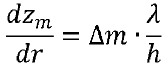
object detection point 13, 13' is tracked for several radar cycles such that the height z is obtained as a function of distance to theobject detection point 13, 13', i.e. as a function of range r. The height z is thus tracked as a function of range r and is assumed to be constant. The equation
- Equation (1) will be solved for Δm, where

- Here, m denotes the geometrical ambiguity index and mGT denotes ground truth geometrical ambiguity index, i.e. the correct geometrical ambiguity index.
- Since the height z of the
object detection point 13, 13' is assumed to be constant, equation (1) will equal zero or be close to zero. Using this knowledge, mGT can be obtained by tracking all possible heights with the assumption that the height does not change and then determine the correct height z. - How the above is achieved will now be described more in detail.
- Here,

- (x; y; z) are the Cartesian coordinates of the
object detection point 13, 13'; - r is the range:
- az is the azimuth angle; and
- el is the elevation angle.
- The phase difference between 2 channels depends on the azimuth of the incident wave, the horizontal spacing between the antennas, the elevation and the vertical spacing between the antennas and the velocity. Now the Range-Doppler map, the output of the 2D-FFT on range and Doppler for each channel, is considered for all 8 channels. Since the two
transmitter antennas - For a given Direction of Arrival in azimuth and elevation, a model for the relative phase between two channels i = (Rxri ; Txti) and j = (Rxrj ; Txtj) is written as:

- ΔΦi,j is the relative phase between two channels;
- Δdi,j is the horizontal distance; Δdi,j = d(rj - ri) + 3d (tj - ti)
- Δhi,j is the vertical distance; Δhi,j = h(tj - ti)
- uaz = sin az;
- uel = sin el;
- v is the relative radial velocity (Doppler); and
- Δti,j is the time difference of different transmitter antennas.
- In the above, the term 3d above, and also as used below, is the value of the horizontal spacing between the
transmitter antennas - The Doppler induces a phase difference between the
transmitter antennas 

- Corresponding phasors for the Doppler phase correction are written as:


- A phasor for the azimuth correction using d1 = 3d is written as:

- A relative phasor between the
transmitter antennas 
- Here, the terms Tx3 and Tx4 relate to the
transmitter antennas - Combining the above results in two possibilities for the elevation phasor brings:


- An elevation phasor is now acquired between the
transmitter antennas 
- In order to be able deal with the ambiguities in a less complicated manner, the measured phase Φel,k is chosen such that 0 ≤ Φel,k < 2n, thus only having 2 branches instead of 3, where the phase is defined modulo 2n according to:



- Investigating different values for m yields:

- It is known that


- It is to be noted that the number of branches depends on the vertical spacing h.
- An example with numbers will now be provided. It is to be noted that this is only an example with the intention of conferring understanding of the present disclosure.
- According to some aspects, each radar cycle comprises 128 ramps in total, 64 ramps for each
transmitter antenna - According to some aspects, for the elevation mode, the second horizontal spacing S2 equals a certain distance d = 0.5λ and the first horizontal spacing S1 equals three times said certain distance, 3d = 2λ, and h = 0.79λ which approximately equals 3.1 mm at 77 GHz.
- This leads to that a main lobe and first side lobe are unambiguous, corresponding to an elevation angle of ±15°. 128 FMCW ramps are used for a radar cycle, toggling between the
transmitter antennas - According to the numerical example,

- The tracker has provided an estimate of the velocity as discussed previously, and this estimate is used to determine which is the correct velocity ambiguity, and thus k = kGT.
- Equation (16) is then re-written as:


- The actual height zGT is linked to the range r and the actual elevation angle elGT as:

- Since it is known that the height z mainly is constant, the following assumption can be made:

- For one value of m, an hypothesis of m, the following is written:


- Equation (22) provides a way to find the correct ambiguity mGT. Since in this case m ∈ {-1, 0}, generally depending on the vertical spacing h, the possible values for


- Evaluating


2 ambiguities, mGT = 0 1 ambiguity 2 ambiguities, mGT = -1 m = 0 0 0 Both possible values of m are considered together. 
m = 1 
0 - Since it is dzm/dr that is of interest, the variation of z should not be tracked as a function of time, but as a function of range. Using the time as base variable means that the velocity has to be corrected, where special care is needed when the relative velocity is 0. Special care is needed around the jump of hypothesis. There are two possibilities:
- The value with m = 0 is the correct one, and the value with m = -1 is driven by

- The value with m = -1 is the correct one, and the value with m = 0 is driven by

- For each of those 2 possibilities, two Kalman Filter are needed; one with a constant height model and one driven by

- At each radar cycle, for each possibility, the two measured values are associated with the nearest tracked value. A comparison of the innovation over the time gives the correct hypothesis. If there is a cycle with only one elevation value, one of the hypothesis is invalidated.
- The present disclosure thus relates to tracking all possible heights z, and with the assumption that the height does not change, pick the correct one zGT.
- With reference to
Figure 6 , the present disclosure also relates to a method for a vehicleradar sensor unit 2 using anantenna arrangement 3, a with at least twotransmitter antennas receiver antennas transmitter antennas radar sensor unit 2 is used for transmitting TDM (Time Division Multiplexed) signals 14a, 14b and for receiving signals that have been reflected by one or more objects during a plurality of radar cycles, such that a plurality of radar detections is acquired. The vertical spacing h exceeds half the free-space wavelength of the transmitted signal. The method comprises: - 26: Determining a first radial velocity of each radar detection by tracking the change of radial distance r to each radar detection for each radar cycle during a plurality of radar cycles.
- 27: Determining a second radial velocity by choosing a measured radial velocity that best matches the first radial velocity. 28: Tracking a plurality of measured heights z as a function of radial distance r for each radar cycle during a plurality of radar cycles.
- 29: Choosing a measured height zGT among the tracked measured heights z that has a minimal change from radar cycle to radar cycle.
- The present disclosure is not limited to the examples above, but may vary freely within the scope of the appended claims. For example, the microwave parts of the
radar sensor arrangement 3 are assumed to be of a previously known design, and according to some aspects theradar sensor arrangement 3 comprises more parts than shown, and is for example connected to a warning and/or information device comprised in thevehicle 1 in a previously known manner. - The calculations and determining procedures are performed by the
processing unit 6, where theprocessing unit 6 should be regarded as a processing unit arrangement that is in the form of one unit or several units that either co-operate or handle different tasks more or less independently. In the case of several units, these may be placed adjacent to each other, or in a distributed manner. - All details given in the example are of course only given as an illustration of the present disclosure, and should not be regarded as limiting in any way.
- In this context, a frame suitably relates to a group of a number of radar signals, or a group of radar signals.
- There may be more or less than the four
receiver antennas - There may be more than the two
transmitter antennas transmitter antennas transmitter antennas - The chirp signals 14a, 14b can comprise signals of any suitable frequency ramp configuration, for example saw-tooth signals and down-ramps where fstart < fstop. Generally, the vehicle radar sensor unit (2) is arranged to transmit any sort of TDM (Time Division Multiplexed) signals 14a, 14b, such as for example FMCW signals.
- The ambiguous part of the negative hypothesis is only needed for over-runnable objects at very close range. A possibility could be to only track the positive/unique elevation value. Care should be taken that there is no false classification for these objects. Another possibility would be to reject all detections outside of the unambiguous zone as being either over-runnable or under-runnable. Due to the high level of noise, this could reduce too much the effective tracking zone.
- As indicated in
Figure 1 , thevehicle 1 comprises asafety control unit 30 and safety means 31, for example an emergency braking system and/or an alarm signal device. Thesafety control unit 30 is arranged to control the safety means 31 in dependence of input from theradar sensor unit 2. Such input may be input via theprocessing unit 6. - Generally, the present disclosure relates to a vehicle
radar sensor unit 2 comprising anantenna arrangement 3, atransmitter unit 4, areceiver unit 5 and aprocessing unit 6, where theantenna arrangement 3 comprises at least twotransmitter antennas receiver antennas transmitter antennas radar sensor unit 2 is arranged to transmit TDM, Time Division Multiplexed, signals 14a, 14b and to receive signals that have been reflected by one or more objects during a plurality of radar cycles, such that a plurality of radar detections is acquired. The vertical spacing h exceeds half the free-space wavelength of the transmitted signal, where saidprocessing unit 5 is arranged to: - determine a first radial velocity of each radar detection by tracking the change of radial distance r to each radar detection for each radar cycle during a plurality of radar cycles;
- determine a second radial velocity by choosing a measured radial velocity that best matches the first radial velocity;
- track a plurality of measured heights z as a function of radial distance r for each radar cycle during a plurality of radar cycles; and to
- choose a measured height zGT among the tracked measured heights z that has a minimal change from radar cycle to radar cycle.
- According to some aspects, said
processing unit 5 is arranged to solve the equation
signal 
- According to some aspects, said
processing unit 5 is arranged to determine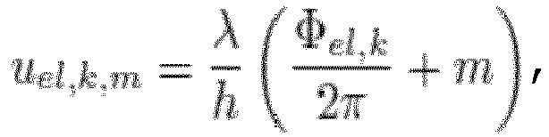
object detection point 13, 13' and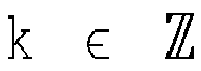
- According to some aspects, said
processing unit 5 is arranged to determine the geometrical ambiguity index m according to the inequality:
- Generally, the present disclosure also relates to a method for a vehicle
radar sensor unit 2 using anantenna arrangement 3 with at least twotransmitter antennas receiver antennas transmitter antennas radar sensor unit 2 is used for transmitting TDM, Time Division Multiplexed, signals 14a, 14b and for receiving signals that have been reflected by one or more objects during a plurality of radar cycles, such that a plurality of radar detections is acquired. The vertical spacing h exceeds half the free-space wavelength of the transmitted signal, where the method comprises: - 26 determining a first radial velocity of each radar detection by tracking the change of radial distance r to each radar detection for each radar cycle during a plurality of radar cycles;
- 27 determining a second radial velocity by choosing a measured radial velocity that best matches the first radial velocity;
- 28 tracking a plurality of measured heights z as a function of radial distance r for each radar cycle during a plurality of radar cycles; and
- 29 choosing a measured height zGT among the tracked measured heights z that has a minimal change from radar cycle to radar cycle.
- According to some aspects, the method comprises solving the equation

signal 
- According to some aspects, the method comprises determining

object detection point 13, 13' and
- According to some aspects, the method comprises determining the geometrical ambiguity index m according to the inequality:

Claims (8)
- A vehicle radar sensor unit (2) comprising an antenna arrangement (3), a transmitter unit (4), a receiver unit (5) and a processing unit (6), where the antenna arrangement (3) comprises at least two transmitter antennas (7, 8) and at least two receiver antennas (9, 10, 11, 12), where two transmitter antennas (7, 8) have a first horizontal spacing (S1) between their respective phase centers (17, 18) and a vertical spacing (h) between their respective phase centers (17, 18), where the vehicle radar sensor unit (2) is arranged to transmit TDM, Time Division Multiplexed, signals (14a, 14b) and to receive signals that have been reflected by one or more objects during a plurality of radar cycles, such that a plurality of radar detections is acquired, characterized in that the vertical spacing (h) exceeds half the free-space wavelength of the transmitted signal, where said processing unit (5) is arranged to:- determine a first radial velocity of each radar detection by tracking the change of radial distance (r) to each radar detection for each radar cycle during a plurality of radar cycles;- determine a second radial velocity by choosing a measured radial velocity that best matches the first radial velocity;- track a plurality of measured heights (z) as a function of radial distance (r) for each radar cycle during a plurality of radar cycles; and to- choose a measured height (zGT) among the tracked measured heights (z) that has a minimal change from radar cycle to radar cycle.
- The vehicle radar sensor unit (2) according to claim 1, characterized in that said processing unit (5) is arranged to solve the equation

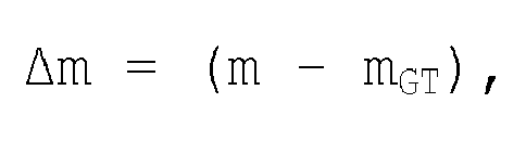
- The vehicle radar sensor unit (2) according to claim 2, characterized in that said processing unit (5) is arranged to determine


- The vehicle radar sensor unit (2) according to any one of the claims 2 or 3, characterized in that said processing unit (5) is arranged to determine the geometrical ambiguity index m according to the inequality:

- A method for a vehicle radar sensor unit (2) using an antenna arrangement (3) with at least two transmitter antennas (7, 8) and at least two receiver antennas (9, 10, 11, 12), where two transmitter antennas (7, 8) have a first horizontal spacing (S1) between their respective phase centers (17, 18) and a vertical spacing (h) between their respective phase centers (17, 18), where the vehicle radar sensor unit (2) is used for transmitting TDM, Time Division Multiplexed, signals (14a, 14b) and for receiving signals that have been reflected by one or more objects during a plurality of radar cycles, such that a plurality of radar detections is acquired, characterized in that the vertical spacing (h) exceeds half the free-space wavelength of the transmitted signal, where the method comprises:(26) determining a first radial velocity of each radar detection by tracking the change of radial distance (r) to each radar detection for each radar cycle during a plurality of radar cycles;(27) determining a second radial velocity by choosing a measured radial velocity that best matches the first radial velocity;(28) tracking a plurality of measured heights (z) as a function of radial distance (r) for each radar cycle during a plurality of radar cycles; and(29) choosing a measured height (zGT) among the tracked measured heights (z) that has a minimal change from radar cycle to radar cycle.
- The method according to claim 5, characterized in that the method comprises solving the equation

- The method according to claim 6, characterized in that the method comprises determining


- The method according to any one of the claims 6 or 7, characterized in that the method comprises determining the geometrical ambiguity index m according to the inequality:

Priority Applications (4)
| Application Number | Priority Date | Filing Date | Title |
|---|---|---|---|
| EP17175314.8A EP3413077B1 (en) | 2017-06-09 | 2017-06-09 | Enhanced vertical object detection for a vehicle radar system |
| CN201880035032.1A CN110678772B (en) | 2017-06-09 | 2018-06-05 | Enhanced Vertical Object Detection for Vehicle Radar Systems |
| US16/618,633 US11209535B2 (en) | 2017-06-09 | 2018-06-05 | Enhanced vertical object detection for a vehicle radar system |
| PCT/EP2018/064752 WO2018224491A1 (en) | 2017-06-09 | 2018-06-05 | Enhanced vertical object detection for a vehicle radar system |
Applications Claiming Priority (1)
| Application Number | Priority Date | Filing Date | Title |
|---|---|---|---|
| EP17175314.8A EP3413077B1 (en) | 2017-06-09 | 2017-06-09 | Enhanced vertical object detection for a vehicle radar system |
Publications (2)
| Publication Number | Publication Date |
|---|---|
| EP3413077A1 true EP3413077A1 (en) | 2018-12-12 |
| EP3413077B1 EP3413077B1 (en) | 2020-02-19 |
Family
ID=59034599
Family Applications (1)
| Application Number | Title | Priority Date | Filing Date |
|---|---|---|---|
| EP17175314.8A Active EP3413077B1 (en) | 2017-06-09 | 2017-06-09 | Enhanced vertical object detection for a vehicle radar system |
Country Status (4)
| Country | Link |
|---|---|
| US (1) | US11209535B2 (en) |
| EP (1) | EP3413077B1 (en) |
| CN (1) | CN110678772B (en) |
| WO (1) | WO2018224491A1 (en) |
Cited By (5)
| Publication number | Priority date | Publication date | Assignee | Title |
|---|---|---|---|---|
| WO2019125747A1 (en) * | 2017-12-22 | 2019-06-27 | Waymo Llc | Automotive radar with antenna arrays having a vertical offset for phase angle measurement in elevation to enable 3d environmental imaging for autonomous vehicles |
| EP3553558A1 (en) * | 2018-04-09 | 2019-10-16 | Mando Corporation | Radar apparatus and antenna apparatus therefor |
| CN110361735A (en) * | 2019-07-22 | 2019-10-22 | 成都纳雷科技有限公司 | A kind of vehicle speed measuring method and device based on velocity radar |
| CN114372364A (en) * | 2022-01-05 | 2022-04-19 | 深圳大学 | Multi-sensor instantaneous vehicle detection method, system, electronic device and storage medium |
| WO2022252311A1 (en) * | 2021-06-04 | 2022-12-08 | 惠州市德赛西威汽车电子股份有限公司 | Method for estimating target fuzzy speed |
Families Citing this family (13)
| Publication number | Priority date | Publication date | Assignee | Title |
|---|---|---|---|---|
| KR102814886B1 (en) * | 2019-03-11 | 2025-05-30 | 주식회사 에이치엘클레무브 | Radar apparatus, antenna apparatus for radar apparatus and control method of radar apparatus |
| US11378674B2 (en) * | 2019-07-12 | 2022-07-05 | GM Global Technology Operations LLC | Object position and movement estimation using radar |
| WO2021056187A1 (en) * | 2019-09-24 | 2021-04-01 | 华为技术有限公司 | Transmitting method and receiving method of speed measurement signal |
| DE102019128020A1 (en) * | 2019-10-17 | 2021-04-22 | Valeo Schalter Und Sensoren Gmbh | Method for estimating an airspeed of a vehicle |
| DE102020109502A1 (en) * | 2020-04-06 | 2021-10-07 | HELLA GmbH & Co. KGaA | Method for determining an angle information |
| WO2021217669A1 (en) * | 2020-04-30 | 2021-11-04 | 华为技术有限公司 | Target detection method and apparatus |
| KR102288673B1 (en) * | 2020-12-28 | 2021-08-12 | 주식회사 비트센싱 | Radar having antennas arranged in horizontal and vertical intervals |
| US12078715B2 (en) * | 2021-03-25 | 2024-09-03 | Aptiv Technologies AG | Radar tracking with model estimates augmented by radar detections |
| EP4092446B1 (en) * | 2021-05-21 | 2024-05-15 | Axis AB | Static scene mapping using radar |
| US11807271B2 (en) * | 2021-07-30 | 2023-11-07 | Ford Global Technologies, Llc | Method, system, and computer program product for resolving level ambiguity for radar systems of autonomous vehicles |
| DE102021123942A1 (en) * | 2021-09-16 | 2023-03-16 | Valeo Schalter Und Sensoren Gmbh | Method for determining at least one elevation variable of an object target of an object, radar system and vehicle with at least one radar system |
| US12271998B2 (en) * | 2021-09-23 | 2025-04-08 | Motional Ad Llc | Spatially and temporally consistent ground modelling with information fusion |
| US12372641B2 (en) * | 2022-12-09 | 2025-07-29 | Nxp B.V. | Ego velocity estimator for radar systems |
Citations (4)
| Publication number | Priority date | Publication date | Assignee | Title |
|---|---|---|---|---|
| DE102009032115A1 (en) * | 2008-07-02 | 2010-01-07 | Adc Automotive Distance Control Systems Gmbh | Radar system with wide detection range and means to avoid ambiguity in the angle measurement |
| US20160033632A1 (en) * | 2014-03-05 | 2016-02-04 | Delphi Technologies, Inc. | Mimo antenna with elevation detection |
| US20160103214A1 (en) * | 2014-10-08 | 2016-04-14 | Src, Inc. | Use of Range-Rate Measurements in a Fusion Tracking System via Projections |
| WO2016055455A1 (en) | 2014-10-06 | 2016-04-14 | Astyx Gmbh | Imaging radar sensor with horizontal digital beam forming and vertical object measurement by phase comparison in mutually offset transmitters |
Family Cites Families (8)
| Publication number | Priority date | Publication date | Assignee | Title |
|---|---|---|---|---|
| US7167126B2 (en) * | 2004-09-01 | 2007-01-23 | The Boeing Company | Radar system and method for determining the height of an object |
| JP5003674B2 (en) * | 2006-03-27 | 2012-08-15 | 株式会社村田製作所 | Radar device and moving body |
| CA2872502C (en) * | 2012-05-04 | 2021-05-18 | Rearden, Llc | System and methods for coping with doppler effects in distributed-input distributed-output wireless systems |
| CN103698759B (en) * | 2013-12-27 | 2015-10-21 | 武汉大学 | A kind of external radiation source radar system based on SFN and signal processing method thereof |
| US20150253419A1 (en) * | 2014-03-05 | 2015-09-10 | Delphi Technologies, Inc. | Mimo antenna with improved grating lobe characteristics |
| US9568600B2 (en) * | 2014-03-05 | 2017-02-14 | Delphi Technologies, Inc. | MIMO antenna with elevation detection |
| DE102014212284A1 (en) * | 2014-06-26 | 2015-12-31 | Robert Bosch Gmbh | MIMO radar measurement method |
| CN104898127A (en) * | 2015-06-17 | 2015-09-09 | 西安电子科技大学 | Multiple-input multiple-output synthetic aperture ladar system and system design method thereof |
-
2017
- 2017-06-09 EP EP17175314.8A patent/EP3413077B1/en active Active
-
2018
- 2018-06-05 CN CN201880035032.1A patent/CN110678772B/en active Active
- 2018-06-05 WO PCT/EP2018/064752 patent/WO2018224491A1/en not_active Ceased
- 2018-06-05 US US16/618,633 patent/US11209535B2/en active Active
Patent Citations (4)
| Publication number | Priority date | Publication date | Assignee | Title |
|---|---|---|---|---|
| DE102009032115A1 (en) * | 2008-07-02 | 2010-01-07 | Adc Automotive Distance Control Systems Gmbh | Radar system with wide detection range and means to avoid ambiguity in the angle measurement |
| US20160033632A1 (en) * | 2014-03-05 | 2016-02-04 | Delphi Technologies, Inc. | Mimo antenna with elevation detection |
| WO2016055455A1 (en) | 2014-10-06 | 2016-04-14 | Astyx Gmbh | Imaging radar sensor with horizontal digital beam forming and vertical object measurement by phase comparison in mutually offset transmitters |
| US20160103214A1 (en) * | 2014-10-08 | 2016-04-14 | Src, Inc. | Use of Range-Rate Measurements in a Fusion Tracking System via Projections |
Cited By (9)
| Publication number | Priority date | Publication date | Assignee | Title |
|---|---|---|---|---|
| WO2019125747A1 (en) * | 2017-12-22 | 2019-06-27 | Waymo Llc | Automotive radar with antenna arrays having a vertical offset for phase angle measurement in elevation to enable 3d environmental imaging for autonomous vehicles |
| KR20200096839A (en) * | 2017-12-22 | 2020-08-13 | 웨이모 엘엘씨 | Automotive radar with antenna arrays with vertical offsets for phase angle measurements at elevation to enable 3D environmental imaging of autonomous-driving vehicles |
| US11698454B2 (en) | 2017-12-22 | 2023-07-11 | Waymo Llc | Radar based three dimensional point cloud for autonomous vehicles |
| EP3553558A1 (en) * | 2018-04-09 | 2019-10-16 | Mando Corporation | Radar apparatus and antenna apparatus therefor |
| US11874363B2 (en) | 2018-04-09 | 2024-01-16 | Hl Klemove Corp. | Radar apparatus and antenna apparatus therefor |
| CN110361735A (en) * | 2019-07-22 | 2019-10-22 | 成都纳雷科技有限公司 | A kind of vehicle speed measuring method and device based on velocity radar |
| WO2022252311A1 (en) * | 2021-06-04 | 2022-12-08 | 惠州市德赛西威汽车电子股份有限公司 | Method for estimating target fuzzy speed |
| CN114372364A (en) * | 2022-01-05 | 2022-04-19 | 深圳大学 | Multi-sensor instantaneous vehicle detection method, system, electronic device and storage medium |
| CN114372364B (en) * | 2022-01-05 | 2025-08-29 | 深圳大学 | Multi-sensor instantaneous vehicle detection method, system, electronic device and storage medium |
Also Published As
| Publication number | Publication date |
|---|---|
| EP3413077B1 (en) | 2020-02-19 |
| CN110678772B (en) | 2023-05-02 |
| US11209535B2 (en) | 2021-12-28 |
| CN110678772A (en) | 2020-01-10 |
| US20200191936A1 (en) | 2020-06-18 |
| WO2018224491A1 (en) | 2018-12-13 |
Similar Documents
| Publication | Publication Date | Title |
|---|---|---|
| EP3413077B1 (en) | Enhanced vertical object detection for a vehicle radar system | |
| KR102799877B1 (en) | Radar system with interleaved serial transmission and parallel reception | |
| US10620305B2 (en) | Multibeam FMCW radar, in particular for automobile | |
| US10871562B2 (en) | Imaging radar sensor with horizontal digital beam forming and vertical object measurement by phase comparison in mutually offset transmitters | |
| US8665137B2 (en) | Radar system with improved angle formation | |
| EP2956795B1 (en) | Multiple-swath stripmap sar imaging | |
| JP6533288B2 (en) | MIMO radar measurement method | |
| CN110431437B (en) | Method and equipment for obtaining the lateral relative velocity component of a radar target | |
| EP0446678B1 (en) | Polystatic correlating radar | |
| JP3989550B2 (en) | Collision warning system | |
| US8299958B2 (en) | Airborne radar having a wide angular coverage, notably for the sense-and-avoid function | |
| CN107076835B (en) | Radar measuring method with different sight distances | |
| EP3147685A1 (en) | A vehicle synthetic aperture radar system | |
| US20120242530A1 (en) | Method for unambiguously determining a range and/or a relative speed of an object, driver assistance device and motor vehicle | |
| US9625562B2 (en) | Method for determining a direction to a signal-emitting object | |
| Abedi et al. | On the use of low-cost radars and machine learning for in-vehicle passenger monitoring | |
| US4862177A (en) | Processor for discriminating between ground and moving targets | |
| Mosito et al. | Detection, tracking and geo-location of moving targets in airborne radar data using a DPCA GMTI technique | |
| US3270340A (en) | Method of echo grouping | |
| EP3480624A1 (en) | Detection of parking row orientation | |
| Wu et al. | Research on Target Detection Algorithm For 77GHz Automotive Radar | |
| Ruegg et al. | Moving target indication with dual frequency millimeter wave SAR | |
| US12529776B2 (en) | Vehicle radar system | |
| US20230003518A1 (en) | Vehicle radar apparatus and method of controlling the same | |
| KR20250017242A (en) | Use of radar sensor with waveguide antenna array for method for determining intrinsic velocity estimates and angle estimates of targets |
Legal Events
| Date | Code | Title | Description |
|---|---|---|---|
| PUAI | Public reference made under article 153(3) epc to a published international application that has entered the european phase |
Free format text: ORIGINAL CODE: 0009012 |
|
| STAA | Information on the status of an ep patent application or granted ep patent |
Free format text: STATUS: THE APPLICATION HAS BEEN PUBLISHED |
|
| AK | Designated contracting states |
Kind code of ref document: A1 Designated state(s): AL AT BE BG CH CY CZ DE DK EE ES FI FR GB GR HR HU IE IS IT LI LT LU LV MC MK MT NL NO PL PT RO RS SE SI SK SM TR |
|
| AX | Request for extension of the european patent |
Extension state: BA ME |
|
| STAA | Information on the status of an ep patent application or granted ep patent |
Free format text: STATUS: REQUEST FOR EXAMINATION WAS MADE |
|
| 17P | Request for examination filed |
Effective date: 20190611 |
|
| RBV | Designated contracting states (corrected) |
Designated state(s): AL AT BE BG CH CY CZ DE DK EE ES FI FR GB GR HR HU IE IS IT LI LT LU LV MC MK MT NL NO PL PT RO RS SE SI SK SM TR |
|
| GRAP | Despatch of communication of intention to grant a patent |
Free format text: ORIGINAL CODE: EPIDOSNIGR1 |
|
| STAA | Information on the status of an ep patent application or granted ep patent |
Free format text: STATUS: GRANT OF PATENT IS INTENDED |
|
| INTG | Intention to grant announced |
Effective date: 20190903 |
|
| GRAS | Grant fee paid |
Free format text: ORIGINAL CODE: EPIDOSNIGR3 |
|
| GRAA | (expected) grant |
Free format text: ORIGINAL CODE: 0009210 |
|
| STAA | Information on the status of an ep patent application or granted ep patent |
Free format text: STATUS: THE PATENT HAS BEEN GRANTED |
|
| AK | Designated contracting states |
Kind code of ref document: B1 Designated state(s): AL AT BE BG CH CY CZ DE DK EE ES FI FR GB GR HR HU IE IS IT LI LT LU LV MC MK MT NL NO PL PT RO RS SE SI SK SM TR |
|
| REG | Reference to a national code |
Ref country code: CH Ref legal event code: EP |
|
| REG | Reference to a national code |
Ref country code: DE Ref legal event code: R096 Ref document number: 602017011857 Country of ref document: DE |
|
| REG | Reference to a national code |
Ref country code: AT Ref legal event code: REF Ref document number: 1235586 Country of ref document: AT Kind code of ref document: T Effective date: 20200315 |
|
| REG | Reference to a national code |
Ref country code: IE Ref legal event code: FG4D |
|
| REG | Reference to a national code |
Ref country code: SE Ref legal event code: TRGR |
|
| REG | Reference to a national code |
Ref country code: NL Ref legal event code: MP Effective date: 20200219 |
|
| PG25 | Lapsed in a contracting state [announced via postgrant information from national office to epo] |
Ref country code: NO Free format text: LAPSE BECAUSE OF FAILURE TO SUBMIT A TRANSLATION OF THE DESCRIPTION OR TO PAY THE FEE WITHIN THE PRESCRIBED TIME-LIMIT Effective date: 20200519 Ref country code: FI Free format text: LAPSE BECAUSE OF FAILURE TO SUBMIT A TRANSLATION OF THE DESCRIPTION OR TO PAY THE FEE WITHIN THE PRESCRIBED TIME-LIMIT Effective date: 20200219 Ref country code: RS Free format text: LAPSE BECAUSE OF FAILURE TO SUBMIT A TRANSLATION OF THE DESCRIPTION OR TO PAY THE FEE WITHIN THE PRESCRIBED TIME-LIMIT Effective date: 20200219 |
|
| REG | Reference to a national code |
Ref country code: LT Ref legal event code: MG4D |
|
| PG25 | Lapsed in a contracting state [announced via postgrant information from national office to epo] |
Ref country code: HR Free format text: LAPSE BECAUSE OF FAILURE TO SUBMIT A TRANSLATION OF THE DESCRIPTION OR TO PAY THE FEE WITHIN THE PRESCRIBED TIME-LIMIT Effective date: 20200219 Ref country code: LV Free format text: LAPSE BECAUSE OF FAILURE TO SUBMIT A TRANSLATION OF THE DESCRIPTION OR TO PAY THE FEE WITHIN THE PRESCRIBED TIME-LIMIT Effective date: 20200219 Ref country code: GR Free format text: LAPSE BECAUSE OF FAILURE TO SUBMIT A TRANSLATION OF THE DESCRIPTION OR TO PAY THE FEE WITHIN THE PRESCRIBED TIME-LIMIT Effective date: 20200520 Ref country code: BG Free format text: LAPSE BECAUSE OF FAILURE TO SUBMIT A TRANSLATION OF THE DESCRIPTION OR TO PAY THE FEE WITHIN THE PRESCRIBED TIME-LIMIT Effective date: 20200519 Ref country code: IS Free format text: LAPSE BECAUSE OF FAILURE TO SUBMIT A TRANSLATION OF THE DESCRIPTION OR TO PAY THE FEE WITHIN THE PRESCRIBED TIME-LIMIT Effective date: 20200619 |
|
| PG25 | Lapsed in a contracting state [announced via postgrant information from national office to epo] |
Ref country code: NL Free format text: LAPSE BECAUSE OF FAILURE TO SUBMIT A TRANSLATION OF THE DESCRIPTION OR TO PAY THE FEE WITHIN THE PRESCRIBED TIME-LIMIT Effective date: 20200219 |
|
| PG25 | Lapsed in a contracting state [announced via postgrant information from national office to epo] |
Ref country code: CZ Free format text: LAPSE BECAUSE OF FAILURE TO SUBMIT A TRANSLATION OF THE DESCRIPTION OR TO PAY THE FEE WITHIN THE PRESCRIBED TIME-LIMIT Effective date: 20200219 Ref country code: PT Free format text: LAPSE BECAUSE OF FAILURE TO SUBMIT A TRANSLATION OF THE DESCRIPTION OR TO PAY THE FEE WITHIN THE PRESCRIBED TIME-LIMIT Effective date: 20200712 Ref country code: SK Free format text: LAPSE BECAUSE OF FAILURE TO SUBMIT A TRANSLATION OF THE DESCRIPTION OR TO PAY THE FEE WITHIN THE PRESCRIBED TIME-LIMIT Effective date: 20200219 Ref country code: DK Free format text: LAPSE BECAUSE OF FAILURE TO SUBMIT A TRANSLATION OF THE DESCRIPTION OR TO PAY THE FEE WITHIN THE PRESCRIBED TIME-LIMIT Effective date: 20200219 Ref country code: LT Free format text: LAPSE BECAUSE OF FAILURE TO SUBMIT A TRANSLATION OF THE DESCRIPTION OR TO PAY THE FEE WITHIN THE PRESCRIBED TIME-LIMIT Effective date: 20200219 Ref country code: EE Free format text: LAPSE BECAUSE OF FAILURE TO SUBMIT A TRANSLATION OF THE DESCRIPTION OR TO PAY THE FEE WITHIN THE PRESCRIBED TIME-LIMIT Effective date: 20200219 Ref country code: SM Free format text: LAPSE BECAUSE OF FAILURE TO SUBMIT A TRANSLATION OF THE DESCRIPTION OR TO PAY THE FEE WITHIN THE PRESCRIBED TIME-LIMIT Effective date: 20200219 Ref country code: ES Free format text: LAPSE BECAUSE OF FAILURE TO SUBMIT A TRANSLATION OF THE DESCRIPTION OR TO PAY THE FEE WITHIN THE PRESCRIBED TIME-LIMIT Effective date: 20200219 Ref country code: RO Free format text: LAPSE BECAUSE OF FAILURE TO SUBMIT A TRANSLATION OF THE DESCRIPTION OR TO PAY THE FEE WITHIN THE PRESCRIBED TIME-LIMIT Effective date: 20200219 |
|
| REG | Reference to a national code |
Ref country code: AT Ref legal event code: MK05 Ref document number: 1235586 Country of ref document: AT Kind code of ref document: T Effective date: 20200219 |
|
| REG | Reference to a national code |
Ref country code: DE Ref legal event code: R097 Ref document number: 602017011857 Country of ref document: DE |
|
| PLBE | No opposition filed within time limit |
Free format text: ORIGINAL CODE: 0009261 |
|
| STAA | Information on the status of an ep patent application or granted ep patent |
Free format text: STATUS: NO OPPOSITION FILED WITHIN TIME LIMIT |
|
| 26N | No opposition filed |
Effective date: 20201120 |
|
| PG25 | Lapsed in a contracting state [announced via postgrant information from national office to epo] |
Ref country code: AT Free format text: LAPSE BECAUSE OF FAILURE TO SUBMIT A TRANSLATION OF THE DESCRIPTION OR TO PAY THE FEE WITHIN THE PRESCRIBED TIME-LIMIT Effective date: 20200219 Ref country code: MC Free format text: LAPSE BECAUSE OF FAILURE TO SUBMIT A TRANSLATION OF THE DESCRIPTION OR TO PAY THE FEE WITHIN THE PRESCRIBED TIME-LIMIT Effective date: 20200219 Ref country code: IT Free format text: LAPSE BECAUSE OF FAILURE TO SUBMIT A TRANSLATION OF THE DESCRIPTION OR TO PAY THE FEE WITHIN THE PRESCRIBED TIME-LIMIT Effective date: 20200219 |
|
| REG | Reference to a national code |
Ref country code: CH Ref legal event code: PL |
|
| PG25 | Lapsed in a contracting state [announced via postgrant information from national office to epo] |
Ref country code: PL Free format text: LAPSE BECAUSE OF FAILURE TO SUBMIT A TRANSLATION OF THE DESCRIPTION OR TO PAY THE FEE WITHIN THE PRESCRIBED TIME-LIMIT Effective date: 20200219 Ref country code: SI Free format text: LAPSE BECAUSE OF FAILURE TO SUBMIT A TRANSLATION OF THE DESCRIPTION OR TO PAY THE FEE WITHIN THE PRESCRIBED TIME-LIMIT Effective date: 20200219 |
|
| PG25 | Lapsed in a contracting state [announced via postgrant information from national office to epo] |
Ref country code: LU Free format text: LAPSE BECAUSE OF NON-PAYMENT OF DUE FEES Effective date: 20200609 |
|
| REG | Reference to a national code |
Ref country code: BE Ref legal event code: MM Effective date: 20200630 |
|
| PG25 | Lapsed in a contracting state [announced via postgrant information from national office to epo] |
Ref country code: IE Free format text: LAPSE BECAUSE OF NON-PAYMENT OF DUE FEES Effective date: 20200609 Ref country code: CH Free format text: LAPSE BECAUSE OF NON-PAYMENT OF DUE FEES Effective date: 20200630 Ref country code: LI Free format text: LAPSE BECAUSE OF NON-PAYMENT OF DUE FEES Effective date: 20200630 |
|
| PG25 | Lapsed in a contracting state [announced via postgrant information from national office to epo] |
Ref country code: BE Free format text: LAPSE BECAUSE OF NON-PAYMENT OF DUE FEES Effective date: 20200630 |
|
| PG25 | Lapsed in a contracting state [announced via postgrant information from national office to epo] |
Ref country code: TR Free format text: LAPSE BECAUSE OF FAILURE TO SUBMIT A TRANSLATION OF THE DESCRIPTION OR TO PAY THE FEE WITHIN THE PRESCRIBED TIME-LIMIT Effective date: 20200219 Ref country code: MT Free format text: LAPSE BECAUSE OF FAILURE TO SUBMIT A TRANSLATION OF THE DESCRIPTION OR TO PAY THE FEE WITHIN THE PRESCRIBED TIME-LIMIT Effective date: 20200219 Ref country code: CY Free format text: LAPSE BECAUSE OF FAILURE TO SUBMIT A TRANSLATION OF THE DESCRIPTION OR TO PAY THE FEE WITHIN THE PRESCRIBED TIME-LIMIT Effective date: 20200219 |
|
| PG25 | Lapsed in a contracting state [announced via postgrant information from national office to epo] |
Ref country code: MK Free format text: LAPSE BECAUSE OF FAILURE TO SUBMIT A TRANSLATION OF THE DESCRIPTION OR TO PAY THE FEE WITHIN THE PRESCRIBED TIME-LIMIT Effective date: 20200219 Ref country code: AL Free format text: LAPSE BECAUSE OF FAILURE TO SUBMIT A TRANSLATION OF THE DESCRIPTION OR TO PAY THE FEE WITHIN THE PRESCRIBED TIME-LIMIT Effective date: 20200219 |
|
| REG | Reference to a national code |
Ref country code: DE Ref legal event code: R081 Ref document number: 602017011857 Country of ref document: DE Owner name: MAGNA ELECTRONICS SWEDEN AB, SE Free format text: FORMER OWNER: VEONEER SWEDEN AB, VARGARDA, SE |
|
| PGFP | Annual fee paid to national office [announced via postgrant information from national office to epo] |
Ref country code: DE Payment date: 20250618 Year of fee payment: 9 |
|
| PGFP | Annual fee paid to national office [announced via postgrant information from national office to epo] |
Ref country code: GB Payment date: 20250625 Year of fee payment: 9 |
|
| PGFP | Annual fee paid to national office [announced via postgrant information from national office to epo] |
Ref country code: FR Payment date: 20250620 Year of fee payment: 9 |
|
| PGFP | Annual fee paid to national office [announced via postgrant information from national office to epo] |
Ref country code: SE Payment date: 20250618 Year of fee payment: 9 |