EP3413055A1 - Method for detecting a covering state and laboratory sample distribution system - Google Patents
Method for detecting a covering state and laboratory sample distribution system Download PDFInfo
- Publication number
- EP3413055A1 EP3413055A1 EP17175340.3A EP17175340A EP3413055A1 EP 3413055 A1 EP3413055 A1 EP 3413055A1 EP 17175340 A EP17175340 A EP 17175340A EP 3413055 A1 EP3413055 A1 EP 3413055A1
- Authority
- EP
- European Patent Office
- Prior art keywords
- laboratory sample
- sample container
- light
- optical power
- covered state
- Prior art date
- Legal status (The legal status is an assumption and is not a legal conclusion. Google has not performed a legal analysis and makes no representation as to the accuracy of the status listed.)
- Granted
Links
Images
Classifications
-
- G—PHYSICS
- G01—MEASURING; TESTING
- G01V—GEOPHYSICS; GRAVITATIONAL MEASUREMENTS; DETECTING MASSES OR OBJECTS; TAGS
- G01V8/00—Prospecting or detecting by optical means
- G01V8/10—Detecting, e.g. by using light barriers
- G01V8/12—Detecting, e.g. by using light barriers using one transmitter and one receiver
- G01V8/16—Detecting, e.g. by using light barriers using one transmitter and one receiver using optical fibres
-
- G—PHYSICS
- G01—MEASURING; TESTING
- G01N—INVESTIGATING OR ANALYSING MATERIALS BY DETERMINING THEIR CHEMICAL OR PHYSICAL PROPERTIES
- G01N21/00—Investigating or analysing materials by the use of optical means, i.e. using sub-millimetre waves, infrared, visible or ultraviolet light
- G01N21/84—Systems specially adapted for particular applications
- G01N21/88—Investigating the presence of flaws or contamination
- G01N21/90—Investigating the presence of flaws or contamination in a container or its contents
- G01N21/9054—Inspection of sealing surface and container finish
-
- G—PHYSICS
- G01—MEASURING; TESTING
- G01D—MEASURING NOT SPECIALLY ADAPTED FOR A SPECIFIC VARIABLE; ARRANGEMENTS FOR MEASURING TWO OR MORE VARIABLES NOT COVERED IN A SINGLE OTHER SUBCLASS; TARIFF METERING APPARATUS; MEASURING OR TESTING NOT OTHERWISE PROVIDED FOR
- G01D5/00—Mechanical means for transferring the output of a sensing member; Means for converting the output of a sensing member to another variable where the form or nature of the sensing member does not constrain the means for converting; Transducers not specially adapted for a specific variable
- G01D5/26—Mechanical means for transferring the output of a sensing member; Means for converting the output of a sensing member to another variable where the form or nature of the sensing member does not constrain the means for converting; Transducers not specially adapted for a specific variable characterised by optical transfer means, i.e. using infrared, visible, or ultraviolet light
- G01D5/32—Mechanical means for transferring the output of a sensing member; Means for converting the output of a sensing member to another variable where the form or nature of the sensing member does not constrain the means for converting; Transducers not specially adapted for a specific variable characterised by optical transfer means, i.e. using infrared, visible, or ultraviolet light with attenuation or whole or partial obturation of beams of light
- G01D5/34—Mechanical means for transferring the output of a sensing member; Means for converting the output of a sensing member to another variable where the form or nature of the sensing member does not constrain the means for converting; Transducers not specially adapted for a specific variable characterised by optical transfer means, i.e. using infrared, visible, or ultraviolet light with attenuation or whole or partial obturation of beams of light the beams of light being detected by photocells
-
- B—PERFORMING OPERATIONS; TRANSPORTING
- B01—PHYSICAL OR CHEMICAL PROCESSES OR APPARATUS IN GENERAL
- B01L—CHEMICAL OR PHYSICAL LABORATORY APPARATUS FOR GENERAL USE
- B01L3/00—Containers or dishes for laboratory use, e.g. laboratory glassware; Droppers
- B01L3/50—Containers for the purpose of retaining a material to be analysed, e.g. test tubes
- B01L3/508—Rigid containers without fluid transport within
- B01L3/5082—Test tubes per se
- B01L3/50825—Closing or opening means, corks, bungs
-
- B—PERFORMING OPERATIONS; TRANSPORTING
- B67—OPENING, CLOSING OR CLEANING BOTTLES, JARS OR SIMILAR CONTAINERS; LIQUID HANDLING
- B67B—APPLYING CLOSURE MEMBERS TO BOTTLES JARS, OR SIMILAR CONTAINERS; OPENING CLOSED CONTAINERS
- B67B3/00—Closing bottles, jars or similar containers by applying caps
- B67B3/26—Applications of control, warning, or safety devices in capping machinery
-
- G—PHYSICS
- G01—MEASURING; TESTING
- G01N—INVESTIGATING OR ANALYSING MATERIALS BY DETERMINING THEIR CHEMICAL OR PHYSICAL PROPERTIES
- G01N21/00—Investigating or analysing materials by the use of optical means, i.e. using sub-millimetre waves, infrared, visible or ultraviolet light
- G01N21/84—Systems specially adapted for particular applications
- G01N21/88—Investigating the presence of flaws or contamination
- G01N21/90—Investigating the presence of flaws or contamination in a container or its contents
- G01N21/909—Investigating the presence of flaws or contamination in a container or its contents in opaque containers or opaque container parts, e.g. cans, tins, caps, labels
-
- G—PHYSICS
- G01—MEASURING; TESTING
- G01N—INVESTIGATING OR ANALYSING MATERIALS BY DETERMINING THEIR CHEMICAL OR PHYSICAL PROPERTIES
- G01N35/00—Automatic analysis not limited to methods or materials provided for in any single one of groups G01N1/00 - G01N33/00; Handling materials therefor
-
- G—PHYSICS
- G01—MEASURING; TESTING
- G01N—INVESTIGATING OR ANALYSING MATERIALS BY DETERMINING THEIR CHEMICAL OR PHYSICAL PROPERTIES
- G01N35/00—Automatic analysis not limited to methods or materials provided for in any single one of groups G01N1/00 - G01N33/00; Handling materials therefor
- G01N35/02—Automatic analysis not limited to methods or materials provided for in any single one of groups G01N1/00 - G01N33/00; Handling materials therefor using a plurality of sample containers moved by a conveyor system past one or more treatment or analysis stations
- G01N35/04—Details of the conveyor system
-
- B—PERFORMING OPERATIONS; TRANSPORTING
- B01—PHYSICAL OR CHEMICAL PROCESSES OR APPARATUS IN GENERAL
- B01L—CHEMICAL OR PHYSICAL LABORATORY APPARATUS FOR GENERAL USE
- B01L2300/00—Additional constructional details
- B01L2300/04—Closures and closing means
- B01L2300/041—Connecting closures to device or container
-
- G—PHYSICS
- G01—MEASURING; TESTING
- G01N—INVESTIGATING OR ANALYSING MATERIALS BY DETERMINING THEIR CHEMICAL OR PHYSICAL PROPERTIES
- G01N35/00—Automatic analysis not limited to methods or materials provided for in any single one of groups G01N1/00 - G01N33/00; Handling materials therefor
- G01N2035/00178—Special arrangements of analysers
- G01N2035/00277—Special precautions to avoid contamination (e.g. enclosures, glove- boxes, sealed sample carriers, disposal of contaminated material)
-
- G—PHYSICS
- G01—MEASURING; TESTING
- G01N—INVESTIGATING OR ANALYSING MATERIALS BY DETERMINING THEIR CHEMICAL OR PHYSICAL PROPERTIES
- G01N35/00—Automatic analysis not limited to methods or materials provided for in any single one of groups G01N1/00 - G01N33/00; Handling materials therefor
- G01N35/02—Automatic analysis not limited to methods or materials provided for in any single one of groups G01N1/00 - G01N33/00; Handling materials therefor using a plurality of sample containers moved by a conveyor system past one or more treatment or analysis stations
- G01N35/04—Details of the conveyor system
- G01N2035/0401—Sample carriers, cuvettes or reaction vessels
- G01N2035/0403—Sample carriers with closing or sealing means
-
- G—PHYSICS
- G01—MEASURING; TESTING
- G01N—INVESTIGATING OR ANALYSING MATERIALS BY DETERMINING THEIR CHEMICAL OR PHYSICAL PROPERTIES
- G01N35/00—Automatic analysis not limited to methods or materials provided for in any single one of groups G01N1/00 - G01N33/00; Handling materials therefor
- G01N35/02—Automatic analysis not limited to methods or materials provided for in any single one of groups G01N1/00 - G01N33/00; Handling materials therefor using a plurality of sample containers moved by a conveyor system past one or more treatment or analysis stations
- G01N35/04—Details of the conveyor system
- G01N2035/0401—Sample carriers, cuvettes or reaction vessels
- G01N2035/0429—Sample carriers adapted for special purposes
- G01N2035/0432—Sample carriers adapted for special purposes integrated with measuring devices
-
- G—PHYSICS
- G01—MEASURING; TESTING
- G01N—INVESTIGATING OR ANALYSING MATERIALS BY DETERMINING THEIR CHEMICAL OR PHYSICAL PROPERTIES
- G01N35/00—Automatic analysis not limited to methods or materials provided for in any single one of groups G01N1/00 - G01N33/00; Handling materials therefor
- G01N35/02—Automatic analysis not limited to methods or materials provided for in any single one of groups G01N1/00 - G01N33/00; Handling materials therefor using a plurality of sample containers moved by a conveyor system past one or more treatment or analysis stations
- G01N35/04—Details of the conveyor system
- G01N2035/0439—Rotary sample carriers, i.e. carousels
-
- G—PHYSICS
- G01—MEASURING; TESTING
- G01N—INVESTIGATING OR ANALYSING MATERIALS BY DETERMINING THEIR CHEMICAL OR PHYSICAL PROPERTIES
- G01N35/00—Automatic analysis not limited to methods or materials provided for in any single one of groups G01N1/00 - G01N33/00; Handling materials therefor
- G01N35/02—Automatic analysis not limited to methods or materials provided for in any single one of groups G01N1/00 - G01N33/00; Handling materials therefor using a plurality of sample containers moved by a conveyor system past one or more treatment or analysis stations
- G01N35/04—Details of the conveyor system
- G01N2035/0474—Details of actuating means for conveyors or pipettes
Definitions
- the invention relates to a method for detecting a covering state of a laboratory sample container and to a corresponding laboratory sample distribution system.
- Laboratory sample distribution systems are typically used in order to distribute a large number of sample containers with respective samples between laboratory stations. Such laboratory stations can, for example, be used in order to determine if certain analytes are present in samples, and in which concentration.
- Sample containers may be covered for example with respective foils. While most sample containers may typically be covered with a respective foil during transport in order to avoid spilling of samples, it may occur that a part of the sample containers is not sealed correctly by the foils. This can lead to spilling of samples and contamination of other samples or of the whole system.
- a covering state may be a state relating to a foil or other cover or covering means being either present or non-present on an orifice of the sample container.
- a covering state may denote a covering degree of the orifice by the foil or other cover or covering means. E.g., it may be detected if the orifice is fully covered, partially covered or not covered by the foil or other cover or covering means.
- the laboratory sample container is at least partially light conducting.
- the laboratory sample container has an orifice being coverable by a dedicated cover.
- the method comprises the following steps:
- a covering state can be reliably detected without the need to use complex technology. It is not necessary to use image recognition or manual intervention in order to determine if a sample container is correctly covered. It is sufficient to inject light into the sample container and to measure a resulting light intensity in order to determine if a cover is placed in the path of the light.
- the light may be injected into the laboratory sample container at a longitudinal end opposite to the orifice, such that the light is conducted along a longitudinal extension of the sample container and leaves the sample container at the orifice.
- the light may be injected into the laboratory sample container at a support holding the laboratory sample container.
- the light is injected into the laboratory sample container using a wave-guiding element.
- a wave-guiding element This allows for using a light source being distant to the sample container, wherein the light is conducted using the wave-guiding element.
- an optical fiber e.g. a glass fiber, can be used.
- the optical power is measured using a sensing means positioned at the measuring location besides the orifice, such that the sensing means is illuminated by light that has been injected into the laboratory sample container and is coupled out from the laboratory sample container if the orifice is not covered or only partially covered by a cover.
- a sensing means may, for example, be embodied as a photo detector. The determination if a sample container is fully covered or not may especially be made using a comparison of the measured optical power with a given or known threshold value.
- the light is coupled out from the laboratory sample container in a region of the laboratory sample container forming the orifice.
- Light is typically prevented from being coupled out by a cover, if the cover correctly covers the orifice.
- the measured optical power of light at the measuring location is normalized by means of a normalizing value, wherein the normalizing value is a measured optical power in the non-covered state of the laboratory sample container, wherein the covered state, the partially covered state or the non-covered state is detected depending on the normalized measured optical power.
- the invention relates further to a laboratory sample distribution system being adapted to perform the inventive method.
- a laboratory sample distribution system being adapted to perform the inventive method.
- all embodiments and variations as disclosed herein can be applied.
- the laboratory sample distribution system comprises a light emitting means, e.g. an LED, being adapted to inject light into a laboratory sample container.
- a light emitting means e.g. an LED
- the laboratory sample distribution system further comprises a sensing means positioned at a measuring location and being configured to measure an optical power of light at the measuring location.
- the laboratory sample distribution system further comprises a control device being adapted to detect a covered state, a partially covered state or a non-covered state of the laboratory sample container depending on the measured optical power.
- the inventive method can be suitably performed.
- a plurality of sample containers can be easily checked regarding their covering state
- control device is configured to influence or suspend further processing of a laboratory sample container depending on the covering state of the sample container. This can, for example, prevent the laboratory sample container not correctly covered by a cover from entering transport systems or regions where spilling could occur.
- the control device may be configured to transport such a sample container securely to a capping station in order to provide for a suitable cover of the laboratory sample container.
- the laboratory sample distribution system comprises a transport device for transporting a plurality of laboratory sample containers, wherein the transport device comprises a number of support elements each having a respective opening for receiving a respective laboratory sample container, wherein the light emitting means is arranged at a position alongside the transport device to inject the light into a laboratory sample container received in a support element.
- Such a transport device may be used in order to transport the sample containers between stations or for other purposes, wherein the detection of the covering state can be made alongside a transport path.
- the transport device is a conveyor belt or conveyor chain.
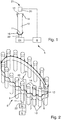
- Fig. 1 shows a part of a laboratory sample distribution system 5 according to a first embodiment of the invention.
- the laboratory sample distribution system 5 is adapted to perform a method according to the invention.
- the laboratory sample distribution system 5 comprises a support 16 for holding a sample container 10.
- the sample container 10 may be filled with a sample that is to be analyzed by analyzing stations that are not shown in the figures. The sample is also not shown.
- the sample container 10 has a lower end 11 and an orifice 12.
- the lower end 11 and the orifice 12 are positioned at opposing longitudinal ends of the sample container 10.
- the orifice 12 is covered by a cover 14.
- the cover 14 is embodied as a foil.
- the laboratory sample distribution system 5 comprises a light emitting means 24 being embodied as a suitable light emitting device, e.g. a LED. Between the light emitting means 24 and the support 16, a wave-guiding element 22 is arranged. By means of the shown arrangement, light emitted from the light emitting means 24 is guided to the support 16 and is coupled into the bottom end of the sample container 10.
- a light emitting means 24 being embodied as a suitable light emitting device, e.g. a LED.
- a wave-guiding element 22 is arranged between the light emitting means 24 and the support 16.
- the sample container 10 is made of material being transparent for the light emitted by the light emitting means 24.
- the material may be glass or transparent plastic.
- the light coupled in at bottom or lower end 11 of the sample container 10 is guided inside the sample container 10 towards the orifice 12.
- the sensing means 20 is positioned at a measuring location 21.
- the sensing means 20 is embodied as a conventional light detector.
- the sensing means 20 is coupled to a control device 6, which is also coupled to the light emitting means 24.
- the control device 6 may e.g. be embodied as a microcontroller.
- a covering state of a sample container 10 is to be determined, i.e. it is to be determined if the sample container 10 is in fact covered by the depicted cover 14, the control device 6 activates the light emitting means 24 such that light is emitted and coupled into the sample container 10. Then, an optical power is detected using the sensing means 20.
- the optical power is below a predefined threshold, it is determined that the sample container 10 is covered, because the cover 14 prevents the light from being emitted out of the sample container 10 at the orifice 12 towards the sensing means 20. If the measured power is above the predefined threshold, it is determined that the sample container 10 is not correctly covered, because light is emitted freely at the orifice 12.
- the threshold(s) may e.g. be determined empirically, e.g. by measuring the optical power in the covered state, in a defined partially covered state and in the non-covered state. This may e.g. be done for different sample containers and/or different sample container materials.
- the measured optical power of light at the measuring location 21 may be normalized by means of a normalizing value, wherein the normalizing value is a measured optical power in the non-covered state of the laboratory sample container 10, wherein the covered state, the partially covered state or the non-covered state is detected depending on the normalized measured optical power.
- the normalizing value is a measured optical power in the non-covered state of the laboratory sample container 10, wherein the covered state, the partially covered state or the non-covered state is detected depending on the normalized measured optical power.
- Fig. 2 shows a part of a laboratory sample distribution system 5 according to a second embodiment of the invention.
- the laboratory sample distribution system 5 comprises a transport device in the form of a conventional conveyor belt 7.
- the conveyor belt 7 comprises a plurality of support elements 8, wherein each support element 8 is embodied for holding a respective sample container 10.
- the conveyor belt 7 is embodied to transport the sample containers 10 comprised in its support elements 8 along a given circular path.
- the covering state of the sample containers 10 being conveyed by means of the conveyor belt 7 may be determined on the flight, i.e. during the conveying process. If a sample container 10 reaches the dedicated position light is emitted from the light emitting means 24. The light is guided using the wave-guiding elements 22 and is coupled into the sample container 10 at its lower end 11. An optical power is measured using the sensing means 20 at the measuring location 21 just above the orifice 12 of the sample container 10. The control device 6 is configured to determine the covering state of the sample container 10 just as described with respect to fig. 1 .
- sample container 10 is not covered by a cover 14. If the sample container 10 not covered by a cover 14 will be checked for its covering state, light can be emitted freely around its orifice 12. Thus, according to the principle described above, it will be detected as being in a non-covered or partially covered state. For example, further operation with this sample container can be prevented or otherwise corrected until it is covered correctly.
Landscapes
- Health & Medical Sciences (AREA)
- Chemical & Material Sciences (AREA)
- General Physics & Mathematics (AREA)
- Physics & Mathematics (AREA)
- General Health & Medical Sciences (AREA)
- Analytical Chemistry (AREA)
- Life Sciences & Earth Sciences (AREA)
- Biochemistry (AREA)
- Immunology (AREA)
- Pathology (AREA)
- Clinical Laboratory Science (AREA)
- Chemical Kinetics & Catalysis (AREA)
- Hematology (AREA)
- Engineering & Computer Science (AREA)
- Mechanical Engineering (AREA)
- General Life Sciences & Earth Sciences (AREA)
- Geophysics (AREA)
- Investigating Or Analysing Materials By Optical Means (AREA)
- Measurement Of Levels Of Liquids Or Fluent Solid Materials (AREA)
- Optical Measuring Cells (AREA)
- Automatic Analysis And Handling Materials Therefor (AREA)
Abstract
Description
- The invention relates to a method for detecting a covering state of a laboratory sample container and to a corresponding laboratory sample distribution system.
- Laboratory sample distribution systems are typically used in order to distribute a large number of sample containers with respective samples between laboratory stations. Such laboratory stations can, for example, be used in order to determine if certain analytes are present in samples, and in which concentration.
- Sample containers may be covered for example with respective foils. While most sample containers may typically be covered with a respective foil during transport in order to avoid spilling of samples, it may occur that a part of the sample containers is not sealed correctly by the foils. This can lead to spilling of samples and contamination of other samples or of the whole system.
- It is thus an object of the present invention to provide for a method for detecting a covering state of a laboratory sample container that allows for a reliable detection of the covering state. It is a further object of the present invention to provide for a corresponding laboratory sample distribution system.
- This object is solved by a method according to claim 1 and a laboratory sample distribution system according to
claim 8. - The invention relates to a method for detecting a covering state of a laboratory sample container. A covering state may be a state relating to a foil or other cover or covering means being either present or non-present on an orifice of the sample container. In addition, a covering state may denote a covering degree of the orifice by the foil or other cover or covering means. E.g., it may be detected if the orifice is fully covered, partially covered or not covered by the foil or other cover or covering means.
- The laboratory sample container is at least partially light conducting. The laboratory sample container has an orifice being coverable by a dedicated cover.
- The method comprises the following steps:
- injecting light into the laboratory sample container,
- measuring an optical power of light at a measuring location, wherein the measuring location is chosen such that the measured optical power depends on the optical power of the light injected into the laboratory sample container and depends on the covering state, and
- detecting a (fully) covered state, a partially covered stated or a non-covered state of the laboratory sample container depending on the measured optical power.
- By means of the inventive method, a covering state can be reliably detected without the need to use complex technology. It is not necessary to use image recognition or manual intervention in order to determine if a sample container is correctly covered. It is sufficient to inject light into the sample container and to measure a resulting light intensity in order to determine if a cover is placed in the path of the light.
- The light may be injected into the laboratory sample container at a longitudinal end opposite to the orifice, such that the light is conducted along a longitudinal extension of the sample container and leaves the sample container at the orifice.
- The light may be injected into the laboratory sample container at a support holding the laboratory sample container.
- According to an embodiment, the light is injected into the laboratory sample container using a wave-guiding element. This allows for using a light source being distant to the sample container, wherein the light is conducted using the wave-guiding element. For example, an optical fiber, e.g. a glass fiber, can be used.
- According to an embodiment, the optical power is measured using a sensing means positioned at the measuring location besides the orifice, such that the sensing means is illuminated by light that has been injected into the laboratory sample container and is coupled out from the laboratory sample container if the orifice is not covered or only partially covered by a cover. Such sensing means may, for example, be embodied as a photo detector. The determination if a sample container is fully covered or not may especially be made using a comparison of the measured optical power with a given or known threshold value.
- According to an embodiment, the light is coupled out from the laboratory sample container in a region of the laboratory sample container forming the orifice. Light is typically prevented from being coupled out by a cover, if the cover correctly covers the orifice.
- According to an embodiment, the measured optical power of light at the measuring location is normalized by means of a normalizing value, wherein the normalizing value is a measured optical power in the non-covered state of the laboratory sample container, wherein the covered state, the partially covered state or the non-covered state is detected depending on the normalized measured optical power. This allows for a simple and suitable reference for determining the covering state.
- The invention relates further to a laboratory sample distribution system being adapted to perform the inventive method. With regard to the method, all embodiments and variations as disclosed herein can be applied.
- The laboratory sample distribution system comprises a light emitting means, e.g. an LED, being adapted to inject light into a laboratory sample container.
- The laboratory sample distribution system further comprises a sensing means positioned at a measuring location and being configured to measure an optical power of light at the measuring location.
- The laboratory sample distribution system further comprises a control device being adapted to detect a covered state, a partially covered state or a non-covered state of the laboratory sample container depending on the measured optical power.
- By means of the inventive laboratory sample distribution system, the inventive method can be suitably performed. E.g. a plurality of sample containers can be easily checked regarding their covering state
- According to an embodiment, the control device is configured to influence or suspend further processing of a laboratory sample container depending on the covering state of the sample container. This can, for example, prevent the laboratory sample container not correctly covered by a cover from entering transport systems or regions where spilling could occur. The control device may be configured to transport such a sample container securely to a capping station in order to provide for a suitable cover of the laboratory sample container.
- According to an embodiment, the laboratory sample distribution system comprises a transport device for transporting a plurality of laboratory sample containers, wherein the transport device comprises a number of support elements each having a respective opening for receiving a respective laboratory sample container, wherein the light emitting means is arranged at a position alongside the transport device to inject the light into a laboratory sample container received in a support element.
- Such a transport device may be used in order to transport the sample containers between stations or for other purposes, wherein the detection of the covering state can be made alongside a transport path.
- According to an embodiment, the transport device is a conveyor belt or conveyor chain.
- The invention will now be described with respect to the attached drawings. In the drawings,
- Fig. 1
- shows a part of a laboratory sample distribution system according to a first embodiment, and
- Fig. 2
- shows a part of a laboratory sample distribution system according to a second embodiment.
-
Fig. 1 shows a part of a laboratorysample distribution system 5 according to a first embodiment of the invention. The laboratorysample distribution system 5 is adapted to perform a method according to the invention. - The laboratory
sample distribution system 5 comprises asupport 16 for holding asample container 10. Thesample container 10 may be filled with a sample that is to be analyzed by analyzing stations that are not shown in the figures. The sample is also not shown. - The
sample container 10 has alower end 11 and anorifice 12. Thelower end 11 and theorifice 12 are positioned at opposing longitudinal ends of thesample container 10. - The
orifice 12 is covered by acover 14. Thecover 14 is embodied as a foil. - Below the
support 16, the laboratorysample distribution system 5 comprises a light emitting means 24 being embodied as a suitable light emitting device, e.g. a LED. Between the light emitting means 24 and thesupport 16, a wave-guidingelement 22 is arranged. By means of the shown arrangement, light emitted from the light emitting means 24 is guided to thesupport 16 and is coupled into the bottom end of thesample container 10. - The
sample container 10 is made of material being transparent for the light emitted by thelight emitting means 24. The material may be glass or transparent plastic. Thus, the light coupled in at bottom orlower end 11 of thesample container 10 is guided inside thesample container 10 towards theorifice 12. - Just above the orifice 12 a sensing means 20 is positioned at a measuring
location 21. The sensing means 20 is embodied as a conventional light detector. - The sensing means 20 is coupled to a
control device 6, which is also coupled to thelight emitting means 24. Thecontrol device 6 may e.g. be embodied as a microcontroller. - If a covering state of a
sample container 10 is to be determined, i.e. it is to be determined if thesample container 10 is in fact covered by the depictedcover 14, thecontrol device 6 activates the light emitting means 24 such that light is emitted and coupled into thesample container 10. Then, an optical power is detected using the sensing means 20. - If the optical power is below a predefined threshold, it is determined that the
sample container 10 is covered, because thecover 14 prevents the light from being emitted out of thesample container 10 at theorifice 12 towards the sensing means 20. If the measured power is above the predefined threshold, it is determined that thesample container 10 is not correctly covered, because light is emitted freely at theorifice 12. It should be noted that also different thresholds can be used for determining a fully covered state, a partially covered state or non-covered state, and that an undefined state may be determined if the optical power is between these thresholds. The threshold(s) may e.g. be determined empirically, e.g. by measuring the optical power in the covered state, in a defined partially covered state and in the non-covered state. This may e.g. be done for different sample containers and/or different sample container materials. - The measured optical power of light at the measuring
location 21 may be normalized by means of a normalizing value, wherein the normalizing value is a measured optical power in the non-covered state of thelaboratory sample container 10, wherein the covered state, the partially covered state or the non-covered state is detected depending on the normalized measured optical power. - This provides for a very easy and reliable determination of a covering state of the
sample container 10. -
Fig. 2 shows a part of a laboratorysample distribution system 5 according to a second embodiment of the invention. - The laboratory
sample distribution system 5 comprises a transport device in the form of aconventional conveyor belt 7. Theconveyor belt 7 comprises a plurality ofsupport elements 8, wherein eachsupport element 8 is embodied for holding arespective sample container 10. Theconveyor belt 7 is embodied to transport thesample containers 10 comprised in itssupport elements 8 along a given circular path. - At the depicted position along the path formed by the
conveyor belt 7 means for detecting a covering state of therespective sample container 10 are arranged. Such means are embodied basically similar tofig. 1 , wherein thesupport 16 is omitted, since thesample container 10 is held by acorresponding support element 8 of theconveyor belt 7. Reference is made to the above description offig. 1 regarding the remaining elements. - The covering state of the
sample containers 10 being conveyed by means of theconveyor belt 7 may be determined on the flight, i.e. during the conveying process. If asample container 10 reaches the dedicated position light is emitted from thelight emitting means 24. The light is guided using the wave-guidingelements 22 and is coupled into thesample container 10 at itslower end 11. An optical power is measured using the sensing means 20 at the measuringlocation 21 just above theorifice 12 of thesample container 10. Thecontrol device 6 is configured to determine the covering state of thesample container 10 just as described with respect tofig. 1 . - As shown in the example of
fig. 2 only onesample container 10 is not covered by acover 14. If thesample container 10 not covered by acover 14 will be checked for its covering state, light can be emitted freely around itsorifice 12. Thus, according to the principle described above, it will be detected as being in a non-covered or partially covered state. For example, further operation with this sample container can be prevented or otherwise corrected until it is covered correctly. - The described operation of the embodiments corresponds to an exemplary embodiment of the inventive method.
Claims (11)
- Method for detecting a covering state of a laboratory sample container (10), wherein the laboratory sample container (10) is at least partially light conducting and wherein the laboratory sample container (10) has an orifice (12) being coverable by a dedicated cover (14), wherein the method comprises the steps:- injecting light into the laboratory sample container (10),- measuring an optical power of light at a measuring location (21), wherein the measuring location (21) is chosen such that the measured optical power depends on the optical power of the light injected into the laboratory sample container (10) and depends on the covering state,- detecting a covered state, a partially covered state and/or a non-covered state of the laboratory sample container (10) depending on the measured optical power.
- Method according to claim 1, characterized in that- the light is injected into the laboratory sample container (10) at a longitudinal end (11) opposite to the orifice (12).
- Method according to one of the preceding claims, characterized in that- the light is injected into the laboratory sample container (10) at a support (16) holding the laboratory sample container (10).
- Method according to one of the preceding claims, characterized in that- the light is injected into the laboratory sample container (10) using a wave-guiding element (22).
- Method according to one of the preceding claims, characterized in that- the optical power is measured using a sensing means (20) positioned at the measuring location (21) besides the orifice (12), such that the sensing means (20) is illuminated by light that has been injected into the laboratory sample container (10) and is coupled out from the laboratory sample container (10), if the orifice (12) is not covered or partially covered by the cover (14).
- Method according to claim 5, characterized in that- the light is coupled out from the laboratory sample container (10) in a region of the laboratory sample container (10) forming the orifice (12).
- Method according to one of the preceding claims, characterized in that- the measured optical power of light at the measuring location (21) is normalized by means of a normalizing value, wherein the normalizing value is a measured optical power in the non-covered state of the laboratory sample container (10), wherein the covered state, the partially covered state and/or the non-covered state is detected depending on the normalized measured optical power.
- Laboratory sample distribution system (5) for performing the method of one of the preceding claims, comprising- a light emitting means (24) being adapted to inject light into a laboratory sample container (10),- a sensing means (20) positioned at a measuring location (21) and being configured to measure an optical power of light at the measuring location (21), and- a control device (6) being adapted to detect a covered state, a partially covered state and/or a non-covered state of the laboratory sample container (10) depending on the measured optical power.
- Laboratory sample distribution system (5) according to claim 8, characterized in that- the control device (6) is configured to influence further processing of a laboratory sample container (10), if a non-covered state or a partially covered state of the laboratory sample container (10) is detected.
- Laboratory sample distribution system (5) according to claim 8 or 9, further comprising:- a transport device (7) for transporting a plurality of laboratory sample containers (10), wherein the transport device (7) comprises a number of support elements (8) each having a respective opening for receiving a respective laboratory sample container (10), wherein the light emitting means (24) is arranged at a position alongside the transport device (7) to inject the light into a laboratory sample container (10) received in a support element (8).
- Laboratory sample distribution system (5) according to claim 10, characterized in that- the transport device (7) is a conveyor belt.
Priority Applications (4)
| Application Number | Priority Date | Filing Date | Title |
|---|---|---|---|
| EP17175340.3A EP3413055B1 (en) | 2017-06-09 | 2017-06-09 | Method for detecting a covering state and laboratory sample distribution system |
| JP2018100389A JP6625162B2 (en) | 2017-06-09 | 2018-05-25 | Method for detecting coating condition and sample distribution system for experiment |
| US15/996,580 US10895476B2 (en) | 2017-06-09 | 2018-06-04 | Method for detecting a covering state and laboratory sample distribution system |
| CN201810587020.1A CN109031451B (en) | 2017-06-09 | 2018-06-08 | Method and laboratory sample distribution system for detecting coverage status |
Applications Claiming Priority (1)
| Application Number | Priority Date | Filing Date | Title |
|---|---|---|---|
| EP17175340.3A EP3413055B1 (en) | 2017-06-09 | 2017-06-09 | Method for detecting a covering state and laboratory sample distribution system |
Publications (2)
| Publication Number | Publication Date |
|---|---|
| EP3413055A1 true EP3413055A1 (en) | 2018-12-12 |
| EP3413055B1 EP3413055B1 (en) | 2021-10-06 |
Family
ID=59053998
Family Applications (1)
| Application Number | Title | Priority Date | Filing Date |
|---|---|---|---|
| EP17175340.3A Active EP3413055B1 (en) | 2017-06-09 | 2017-06-09 | Method for detecting a covering state and laboratory sample distribution system |
Country Status (4)
| Country | Link |
|---|---|
| US (1) | US10895476B2 (en) |
| EP (1) | EP3413055B1 (en) |
| JP (1) | JP6625162B2 (en) |
| CN (1) | CN109031451B (en) |
Families Citing this family (1)
| Publication number | Priority date | Publication date | Assignee | Title |
|---|---|---|---|---|
| KR20240142467A (en) * | 2022-01-28 | 2024-09-30 | 애보트 라피드 다이어그노스틱스 인터내셔널 언리미티드 컴퍼니 | Container closure indicator system |
Citations (4)
| Publication number | Priority date | Publication date | Assignee | Title |
|---|---|---|---|---|
| US5171979A (en) * | 1990-07-20 | 1992-12-15 | Eastman Kodak Company | Device for scanning containers filled with liquid |
| JPH09169392A (en) * | 1995-12-20 | 1997-06-30 | Mitsubishi Heavy Ind Ltd | Image type capping state tester |
| US20130017595A1 (en) * | 2009-12-28 | 2013-01-17 | Hitachi High-Technologies Corporation | Analytical apparatus and detection method employed in analytical apparatus |
| CN102486824B (en) * | 2010-12-02 | 2016-05-04 | 深圳迈瑞生物医疗电子股份有限公司 | A kind of bar code scanner and blood cell analyzer thereof |
Family Cites Families (16)
| Publication number | Priority date | Publication date | Assignee | Title |
|---|---|---|---|---|
| JPS544160A (en) * | 1977-06-11 | 1979-01-12 | Omron Tateisi Electronics Co | Cap testing system for bottle-shaped containers |
| JPH0610856U (en) * | 1992-01-31 | 1994-02-10 | 株式会社インターテック | Microplate reader |
| JP3203773B2 (en) * | 1992-06-25 | 2001-08-27 | 株式会社日立製作所 | Automatic opening device |
| EP0647846A1 (en) * | 1993-10-08 | 1995-04-12 | Elpatronic Ag | Method and device for inspecting transparent articles |
| FR2784464B1 (en) | 1998-10-08 | 2000-12-22 | Andre Chojnacki | OPTICAL MEASURING HEAD, IN PARTICULAR FOR AN AUTOMATIC CHEMICAL OR BIOCHEMICAL REACTION ANALYZER |
| US6473170B2 (en) * | 2001-01-19 | 2002-10-29 | White Cap, Inc. | Linear optical sensor for a closure |
| US6654117B1 (en) * | 2001-09-04 | 2003-11-25 | The Quaker Oats Company | Bottle cap sensor apparatus and method |
| JP4210306B2 (en) | 2007-01-15 | 2009-01-14 | 株式会社アイディエス | Test tube automatic opening device |
| JP5426498B2 (en) * | 2010-08-18 | 2014-02-26 | シスメックス株式会社 | Sample suction device |
| CN202164088U (en) | 2011-03-09 | 2012-03-14 | 重庆树荣化工有限公司 | On-line plastic-bottle aluminum foil detecting and rejecting machine |
| CN203268433U (en) | 2013-04-01 | 2013-11-06 | 安徽华佗国药股份有限公司 | Alarm device for aluminum foil sealing of medicine bottles |
| CN203758920U (en) | 2013-12-28 | 2014-08-06 | 楚天科技股份有限公司 | Device of automatically detecting bottle cap and bottle bottom |
| CN104492727A (en) | 2015-01-08 | 2015-04-08 | 常州永一包装科技有限公司 | Multifunctional aluminum foil detecting and removing machine |
| CN104849768A (en) * | 2015-04-17 | 2015-08-19 | 江西新正源机电科技有限公司 | Method for detecting if sealing gasket of bottle cap is installed in place |
| CN205442598U (en) * | 2015-12-29 | 2016-08-10 | 河北德容塑料包装制品股份有限公司 | Plastic bottle packing leak hunting device |
| EP3444616A1 (en) * | 2017-08-18 | 2019-02-20 | Roche Diagnostics GmbH | Method for determining, whether an opening of a laboratory sample container is open or closed, laboratory device and laboratory automation system |
-
2017
- 2017-06-09 EP EP17175340.3A patent/EP3413055B1/en active Active
-
2018
- 2018-05-25 JP JP2018100389A patent/JP6625162B2/en active Active
- 2018-06-04 US US15/996,580 patent/US10895476B2/en active Active
- 2018-06-08 CN CN201810587020.1A patent/CN109031451B/en active Active
Patent Citations (4)
| Publication number | Priority date | Publication date | Assignee | Title |
|---|---|---|---|---|
| US5171979A (en) * | 1990-07-20 | 1992-12-15 | Eastman Kodak Company | Device for scanning containers filled with liquid |
| JPH09169392A (en) * | 1995-12-20 | 1997-06-30 | Mitsubishi Heavy Ind Ltd | Image type capping state tester |
| US20130017595A1 (en) * | 2009-12-28 | 2013-01-17 | Hitachi High-Technologies Corporation | Analytical apparatus and detection method employed in analytical apparatus |
| CN102486824B (en) * | 2010-12-02 | 2016-05-04 | 深圳迈瑞生物医疗电子股份有限公司 | A kind of bar code scanner and blood cell analyzer thereof |
Also Published As
| Publication number | Publication date |
|---|---|
| US20180356259A1 (en) | 2018-12-13 |
| CN109031451A (en) | 2018-12-18 |
| JP6625162B2 (en) | 2019-12-25 |
| US10895476B2 (en) | 2021-01-19 |
| JP2019002914A (en) | 2019-01-10 |
| CN109031451B (en) | 2021-09-07 |
| EP3413055B1 (en) | 2021-10-06 |
Similar Documents
| Publication | Publication Date | Title |
|---|---|---|
| CN101131392B (en) | Specimen Processing System | |
| US11125601B2 (en) | Laboratory automation system including improved processing of a laboratory sample by optical and tip position sensing | |
| CN102713638B (en) | The detection method that analytical equipment and analytical equipment use | |
| US3827812A (en) | Method of and apparatus for testing the condition of bottles | |
| EP2976204B1 (en) | Method and system for checking the color quality of unordered preforms | |
| CN104335051B (en) | Automatic analysis device | |
| US6872895B2 (en) | Apparatus and method for providing spatially-selective on-line mass or volume measurements of manufactured articles | |
| EP2770317A1 (en) | Apparatus for determining a vertical position of at least one interface between a first component and at least one second component and laboratory automation system | |
| US12085482B2 (en) | Method and apparatus for recognizing the presence of leakages from sealed containers | |
| US9285348B2 (en) | Automated system for handling components of a chromatographic system | |
| EP3617695B1 (en) | Egg inspection device | |
| EP3413055B1 (en) | Method for detecting a covering state and laboratory sample distribution system | |
| CN106604870A (en) | Measurement of the fluorescence of an indicator in a gas-tight packaging, which contains products having limited storage life | |
| CN106415250A (en) | Inspection of containers | |
| EP3273393A1 (en) | Package inspection system | |
| KR101866181B1 (en) | Apparatus for detecting foreign material in container | |
| KR102290888B1 (en) | Apparatus for radioactivity inspection and metal foreign matter detecting | |
| JP2015010965A (en) | Foreign matter inspection device | |
| EP3444616A1 (en) | Method for determining, whether an opening of a laboratory sample container is open or closed, laboratory device and laboratory automation system | |
| JP4092312B2 (en) | Interface detection device and method, volume measuring device | |
| US12017216B2 (en) | Method and laboratory system to process a laboratory carrier based on a feature of a test liquid in the laboratory carrier | |
| CN112805569B (en) | Sample processing system | |
| EP4446747A1 (en) | Chute arrangement and cap-removal apparatus | |
| EP3782940A1 (en) | Inspection system | |
| JP2020033053A (en) | Processing device and processing method |
Legal Events
| Date | Code | Title | Description |
|---|---|---|---|
| PUAI | Public reference made under article 153(3) epc to a published international application that has entered the european phase |
Free format text: ORIGINAL CODE: 0009012 |
|
| STAA | Information on the status of an ep patent application or granted ep patent |
Free format text: STATUS: THE APPLICATION HAS BEEN PUBLISHED |
|
| AK | Designated contracting states |
Kind code of ref document: A1 Designated state(s): AL AT BE BG CH CY CZ DE DK EE ES FI FR GB GR HR HU IE IS IT LI LT LU LV MC MK MT NL NO PL PT RO RS SE SI SK SM TR |
|
| AX | Request for extension of the european patent |
Extension state: BA ME |
|
| STAA | Information on the status of an ep patent application or granted ep patent |
Free format text: STATUS: REQUEST FOR EXAMINATION WAS MADE |
|
| 17P | Request for examination filed |
Effective date: 20190604 |
|
| RBV | Designated contracting states (corrected) |
Designated state(s): AL AT BE BG CH CY CZ DE DK EE ES FI FR GB GR HR HU IE IS IT LI LT LU LV MC MK MT NL NO PL PT RO RS SE SI SK SM TR |
|
| REG | Reference to a national code |
Ref country code: DE Ref legal event code: R079 Ref document number: 602017047047 Country of ref document: DE Free format text: PREVIOUS MAIN CLASS: G01N0035000000 Ipc: G01N0035040000 |
|
| GRAJ | Information related to disapproval of communication of intention to grant by the applicant or resumption of examination proceedings by the epo deleted |
Free format text: ORIGINAL CODE: EPIDOSDIGR1 |
|
| STAA | Information on the status of an ep patent application or granted ep patent |
Free format text: STATUS: GRANT OF PATENT IS INTENDED |
|
| GRAP | Despatch of communication of intention to grant a patent |
Free format text: ORIGINAL CODE: EPIDOSNIGR1 |
|
| RIC1 | Information provided on ipc code assigned before grant |
Ipc: G01N 35/04 20060101AFI20210415BHEP Ipc: G01N 35/00 20060101ALI20210415BHEP Ipc: B67B 3/26 20060101ALI20210415BHEP Ipc: G01N 21/90 20060101ALI20210415BHEP |
|
| INTG | Intention to grant announced |
Effective date: 20210507 |
|
| GRAS | Grant fee paid |
Free format text: ORIGINAL CODE: EPIDOSNIGR3 |
|
| GRAA | (expected) grant |
Free format text: ORIGINAL CODE: 0009210 |
|
| STAA | Information on the status of an ep patent application or granted ep patent |
Free format text: STATUS: THE PATENT HAS BEEN GRANTED |
|
| AK | Designated contracting states |
Kind code of ref document: B1 Designated state(s): AL AT BE BG CH CY CZ DE DK EE ES FI FR GB GR HR HU IE IS IT LI LT LU LV MC MK MT NL NO PL PT RO RS SE SI SK SM TR |
|
| REG | Reference to a national code |
Ref country code: GB Ref legal event code: FG4D |
|
| REG | Reference to a national code |
Ref country code: CH Ref legal event code: EP Ref country code: AT Ref legal event code: REF Ref document number: 1436650 Country of ref document: AT Kind code of ref document: T Effective date: 20211015 |
|
| REG | Reference to a national code |
Ref country code: DE Ref legal event code: R096 Ref document number: 602017047047 Country of ref document: DE |
|
| REG | Reference to a national code |
Ref country code: IE Ref legal event code: FG4D |
|
| REG | Reference to a national code |
Ref country code: LT Ref legal event code: MG9D |
|
| REG | Reference to a national code |
Ref country code: NL Ref legal event code: MP Effective date: 20211006 |
|
| REG | Reference to a national code |
Ref country code: AT Ref legal event code: MK05 Ref document number: 1436650 Country of ref document: AT Kind code of ref document: T Effective date: 20211006 |
|
| PG25 | Lapsed in a contracting state [announced via postgrant information from national office to epo] |
Ref country code: RS Free format text: LAPSE BECAUSE OF FAILURE TO SUBMIT A TRANSLATION OF THE DESCRIPTION OR TO PAY THE FEE WITHIN THE PRESCRIBED TIME-LIMIT Effective date: 20211006 Ref country code: LT Free format text: LAPSE BECAUSE OF FAILURE TO SUBMIT A TRANSLATION OF THE DESCRIPTION OR TO PAY THE FEE WITHIN THE PRESCRIBED TIME-LIMIT Effective date: 20211006 Ref country code: FI Free format text: LAPSE BECAUSE OF FAILURE TO SUBMIT A TRANSLATION OF THE DESCRIPTION OR TO PAY THE FEE WITHIN THE PRESCRIBED TIME-LIMIT Effective date: 20211006 Ref country code: BG Free format text: LAPSE BECAUSE OF FAILURE TO SUBMIT A TRANSLATION OF THE DESCRIPTION OR TO PAY THE FEE WITHIN THE PRESCRIBED TIME-LIMIT Effective date: 20220106 Ref country code: AT Free format text: LAPSE BECAUSE OF FAILURE TO SUBMIT A TRANSLATION OF THE DESCRIPTION OR TO PAY THE FEE WITHIN THE PRESCRIBED TIME-LIMIT Effective date: 20211006 |
|
| PG25 | Lapsed in a contracting state [announced via postgrant information from national office to epo] |
Ref country code: IS Free format text: LAPSE BECAUSE OF FAILURE TO SUBMIT A TRANSLATION OF THE DESCRIPTION OR TO PAY THE FEE WITHIN THE PRESCRIBED TIME-LIMIT Effective date: 20220206 Ref country code: SE Free format text: LAPSE BECAUSE OF FAILURE TO SUBMIT A TRANSLATION OF THE DESCRIPTION OR TO PAY THE FEE WITHIN THE PRESCRIBED TIME-LIMIT Effective date: 20211006 Ref country code: PT Free format text: LAPSE BECAUSE OF FAILURE TO SUBMIT A TRANSLATION OF THE DESCRIPTION OR TO PAY THE FEE WITHIN THE PRESCRIBED TIME-LIMIT Effective date: 20220207 Ref country code: PL Free format text: LAPSE BECAUSE OF FAILURE TO SUBMIT A TRANSLATION OF THE DESCRIPTION OR TO PAY THE FEE WITHIN THE PRESCRIBED TIME-LIMIT Effective date: 20211006 Ref country code: NO Free format text: LAPSE BECAUSE OF FAILURE TO SUBMIT A TRANSLATION OF THE DESCRIPTION OR TO PAY THE FEE WITHIN THE PRESCRIBED TIME-LIMIT Effective date: 20220106 Ref country code: NL Free format text: LAPSE BECAUSE OF FAILURE TO SUBMIT A TRANSLATION OF THE DESCRIPTION OR TO PAY THE FEE WITHIN THE PRESCRIBED TIME-LIMIT Effective date: 20211006 Ref country code: LV Free format text: LAPSE BECAUSE OF FAILURE TO SUBMIT A TRANSLATION OF THE DESCRIPTION OR TO PAY THE FEE WITHIN THE PRESCRIBED TIME-LIMIT Effective date: 20211006 Ref country code: HR Free format text: LAPSE BECAUSE OF FAILURE TO SUBMIT A TRANSLATION OF THE DESCRIPTION OR TO PAY THE FEE WITHIN THE PRESCRIBED TIME-LIMIT Effective date: 20211006 Ref country code: GR Free format text: LAPSE BECAUSE OF FAILURE TO SUBMIT A TRANSLATION OF THE DESCRIPTION OR TO PAY THE FEE WITHIN THE PRESCRIBED TIME-LIMIT Effective date: 20220107 Ref country code: ES Free format text: LAPSE BECAUSE OF FAILURE TO SUBMIT A TRANSLATION OF THE DESCRIPTION OR TO PAY THE FEE WITHIN THE PRESCRIBED TIME-LIMIT Effective date: 20211006 |
|
| REG | Reference to a national code |
Ref country code: DE Ref legal event code: R097 Ref document number: 602017047047 Country of ref document: DE |
|
| PG25 | Lapsed in a contracting state [announced via postgrant information from national office to epo] |
Ref country code: SM Free format text: LAPSE BECAUSE OF FAILURE TO SUBMIT A TRANSLATION OF THE DESCRIPTION OR TO PAY THE FEE WITHIN THE PRESCRIBED TIME-LIMIT Effective date: 20211006 Ref country code: SK Free format text: LAPSE BECAUSE OF FAILURE TO SUBMIT A TRANSLATION OF THE DESCRIPTION OR TO PAY THE FEE WITHIN THE PRESCRIBED TIME-LIMIT Effective date: 20211006 Ref country code: RO Free format text: LAPSE BECAUSE OF FAILURE TO SUBMIT A TRANSLATION OF THE DESCRIPTION OR TO PAY THE FEE WITHIN THE PRESCRIBED TIME-LIMIT Effective date: 20211006 Ref country code: EE Free format text: LAPSE BECAUSE OF FAILURE TO SUBMIT A TRANSLATION OF THE DESCRIPTION OR TO PAY THE FEE WITHIN THE PRESCRIBED TIME-LIMIT Effective date: 20211006 Ref country code: DK Free format text: LAPSE BECAUSE OF FAILURE TO SUBMIT A TRANSLATION OF THE DESCRIPTION OR TO PAY THE FEE WITHIN THE PRESCRIBED TIME-LIMIT Effective date: 20211006 Ref country code: CZ Free format text: LAPSE BECAUSE OF FAILURE TO SUBMIT A TRANSLATION OF THE DESCRIPTION OR TO PAY THE FEE WITHIN THE PRESCRIBED TIME-LIMIT Effective date: 20211006 |
|
| PLBE | No opposition filed within time limit |
Free format text: ORIGINAL CODE: 0009261 |
|
| STAA | Information on the status of an ep patent application or granted ep patent |
Free format text: STATUS: NO OPPOSITION FILED WITHIN TIME LIMIT |
|
| 26N | No opposition filed |
Effective date: 20220707 |
|
| PG25 | Lapsed in a contracting state [announced via postgrant information from national office to epo] |
Ref country code: AL Free format text: LAPSE BECAUSE OF FAILURE TO SUBMIT A TRANSLATION OF THE DESCRIPTION OR TO PAY THE FEE WITHIN THE PRESCRIBED TIME-LIMIT Effective date: 20211006 |
|
| PG25 | Lapsed in a contracting state [announced via postgrant information from national office to epo] |
Ref country code: SI Free format text: LAPSE BECAUSE OF FAILURE TO SUBMIT A TRANSLATION OF THE DESCRIPTION OR TO PAY THE FEE WITHIN THE PRESCRIBED TIME-LIMIT Effective date: 20211006 |
|
| PG25 | Lapsed in a contracting state [announced via postgrant information from national office to epo] |
Ref country code: MC Free format text: LAPSE BECAUSE OF FAILURE TO SUBMIT A TRANSLATION OF THE DESCRIPTION OR TO PAY THE FEE WITHIN THE PRESCRIBED TIME-LIMIT Effective date: 20211006 |
|
| REG | Reference to a national code |
Ref country code: BE Ref legal event code: MM Effective date: 20220630 |
|
| PG25 | Lapsed in a contracting state [announced via postgrant information from national office to epo] |
Ref country code: LU Free format text: LAPSE BECAUSE OF NON-PAYMENT OF DUE FEES Effective date: 20220609 Ref country code: IE Free format text: LAPSE BECAUSE OF NON-PAYMENT OF DUE FEES Effective date: 20220609 |
|
| PG25 | Lapsed in a contracting state [announced via postgrant information from national office to epo] |
Ref country code: BE Free format text: LAPSE BECAUSE OF NON-PAYMENT OF DUE FEES Effective date: 20220630 |
|
| PG25 | Lapsed in a contracting state [announced via postgrant information from national office to epo] |
Ref country code: HU Free format text: LAPSE BECAUSE OF FAILURE TO SUBMIT A TRANSLATION OF THE DESCRIPTION OR TO PAY THE FEE WITHIN THE PRESCRIBED TIME-LIMIT; INVALID AB INITIO Effective date: 20170609 |
|
| PG25 | Lapsed in a contracting state [announced via postgrant information from national office to epo] |
Ref country code: MK Free format text: LAPSE BECAUSE OF FAILURE TO SUBMIT A TRANSLATION OF THE DESCRIPTION OR TO PAY THE FEE WITHIN THE PRESCRIBED TIME-LIMIT Effective date: 20211006 Ref country code: CY Free format text: LAPSE BECAUSE OF FAILURE TO SUBMIT A TRANSLATION OF THE DESCRIPTION OR TO PAY THE FEE WITHIN THE PRESCRIBED TIME-LIMIT Effective date: 20211006 |
|
| PG25 | Lapsed in a contracting state [announced via postgrant information from national office to epo] |
Ref country code: TR Free format text: LAPSE BECAUSE OF FAILURE TO SUBMIT A TRANSLATION OF THE DESCRIPTION OR TO PAY THE FEE WITHIN THE PRESCRIBED TIME-LIMIT Effective date: 20211006 |
|
| PG25 | Lapsed in a contracting state [announced via postgrant information from national office to epo] |
Ref country code: MT Free format text: LAPSE BECAUSE OF FAILURE TO SUBMIT A TRANSLATION OF THE DESCRIPTION OR TO PAY THE FEE WITHIN THE PRESCRIBED TIME-LIMIT Effective date: 20211006 |
|
| PGFP | Annual fee paid to national office [announced via postgrant information from national office to epo] |
Ref country code: DE Payment date: 20250520 Year of fee payment: 9 |
|
| PGFP | Annual fee paid to national office [announced via postgrant information from national office to epo] |
Ref country code: GB Payment date: 20250520 Year of fee payment: 9 |
|
| PGFP | Annual fee paid to national office [announced via postgrant information from national office to epo] |
Ref country code: IT Payment date: 20250520 Year of fee payment: 9 |
|
| PGFP | Annual fee paid to national office [announced via postgrant information from national office to epo] |
Ref country code: FR Payment date: 20250520 Year of fee payment: 9 |
|
| PGFP | Annual fee paid to national office [announced via postgrant information from national office to epo] |
Ref country code: CH Payment date: 20250701 Year of fee payment: 9 |