EP3413025A1 - Total air temperature probe with reduced icing sensor flow passage geometry - Google Patents
Total air temperature probe with reduced icing sensor flow passage geometry Download PDFInfo
- Publication number
- EP3413025A1 EP3413025A1 EP18175038.1A EP18175038A EP3413025A1 EP 3413025 A1 EP3413025 A1 EP 3413025A1 EP 18175038 A EP18175038 A EP 18175038A EP 3413025 A1 EP3413025 A1 EP 3413025A1
- Authority
- EP
- European Patent Office
- Prior art keywords
- air temperature
- total air
- protrusions
- entrance
- flow tube
- Prior art date
- Legal status (The legal status is an assumption and is not a legal conclusion. Google has not performed a legal analysis and makes no representation as to the accuracy of the status listed.)
- Granted
Links
Images




Classifications
-
- G—PHYSICS
- G01—MEASURING; TESTING
- G01K—MEASURING TEMPERATURE; MEASURING QUANTITY OF HEAT; THERMALLY-SENSITIVE ELEMENTS NOT OTHERWISE PROVIDED FOR
- G01K1/00—Details of thermometers not specially adapted for particular types of thermometer
- G01K1/08—Protective devices, e.g. casings
-
- G—PHYSICS
- G01—MEASURING; TESTING
- G01K—MEASURING TEMPERATURE; MEASURING QUANTITY OF HEAT; THERMALLY-SENSITIVE ELEMENTS NOT OTHERWISE PROVIDED FOR
- G01K13/00—Thermometers specially adapted for specific purposes
- G01K13/02—Thermometers specially adapted for specific purposes for measuring temperature of moving fluids or granular materials capable of flow
- G01K13/028—Thermometers specially adapted for specific purposes for measuring temperature of moving fluids or granular materials capable of flow for use in total air temperature [TAT] probes
-
- G—PHYSICS
- G01—MEASURING; TESTING
- G01K—MEASURING TEMPERATURE; MEASURING QUANTITY OF HEAT; THERMALLY-SENSITIVE ELEMENTS NOT OTHERWISE PROVIDED FOR
- G01K13/00—Thermometers specially adapted for specific purposes
- G01K13/02—Thermometers specially adapted for specific purposes for measuring temperature of moving fluids or granular materials capable of flow
- G01K13/024—Thermometers specially adapted for specific purposes for measuring temperature of moving fluids or granular materials capable of flow of moving gases
Definitions
- the present disclosure relates to sensors, and in particular, to total air temperature (TAT) probes.
- TAT total air temperature
- TAT probes are mounted on aircraft to measure the total air temperature on the skin of the aircraft. More specifically, TAT probes cause the surrounding airflow to stagnate and then measure the temperature of the stagnated air. Often TAT probes operate in environmental conditions that may include rain, ice, ice crystals, and other particles. Such small particles can interfere with sensor passage flow and can accumulate on the sensor assembly of the TAT probe, which may result in erroneous TAT measurement.
- a total air temperature probe includes a housing defining a total air temperature sensor flow passage and a sensor assembly positioned within the total air temperature sensor flow passage.
- the sensor assembly includes an element flow tube, and a sensing element within the element flow tube.
- An upper portion of the element flow tube is an entrance including a plurality of protrusions that extend in an upstream direction.
- a total air temperature probe includes a housing, including an inlet scoop and a total air temperature sensor flow passage downstream of the inlet scoop, and a sensor assembly positioned in the total air temperature sensor flow passage.
- the sensor assembly includes an annular element flow tube having an entrance comprising the upper portion of the element flow tube and a sensing element within the element flow tube and downstream of the entrance.
- the entrance has protrusions that form peaks and valleys around the entrance, the protrusions extending upstream into the total air temperature sensor flow passage.
- a total air temperature probe includes a housing including an inlet scoop, an outlet, a total air temperature sensor flow passage downstream of the inlet scoop, and a flow separation bend between the inlet scoop and the total air temperature sensor flow passage.
- the total air temperature probe also includes a sensor assembly positioned in the total air temperature sensor flow passage.
- the sensor assembly includes an element flow tube having an entrance comprising the upper portion of the element flow tube, a sensing element within the element flow tube, and a flow liner positioned annularly around the element flow tube. The entrance of the element flow tube has protrusions extending upstream into the total air temperature sensor flow passage.
- the present disclosure is a total air temperature (TAT) probe that includes an element flow tube with an entrance having protrusions extending toward an airflow.
- TAT total air temperature
- the protrusions reduce substantial ice accretion on the entrance, decreasing TAT measurement errors.
- the TAT probe has improved functionality in severe icing conditions.
- FIG. 1A is a cross-sectional view of TAT probe 10.
- FIG. 1B is a partial enlarged cross-sectional view of TAT probe 10 showing accretion of ice I on element flow tube 12.
- TAT probe 10 includes housing 14, mounting flange 16 (shown in FIG. 1A ), and sensor assembly 18. Housing 14 includes inlet scoop 20, outlet 22 (shown in FIG. 1A ), main airflow passage 24, flow separation bend 26, TAT sensor flow passage 28, bleed holes 29, and exit ports 30 (shown in FIG. 1A ).
- Sensor assembly 18 includes element flow tube 12, sensing elements 32, tip support 34, and flow liner 36.
- Element flow tube 12 includes main body 38 and entrance 40. Entrance 40 includes protrusions 42, which form peaks 44 and valleys 46 at entrance 40. Also shown in FIGS. 1A and 1B are airflow A, particles P, and ice I (shown in FIG. 1B ).
- TAT probe 10 has housing 14 attached to mounting flange 16. Housing 14 is heated and provides structure for TAT probe 10. Mounting flange 16 mounts TAT probe 10 to an aircraft. Sensor assembly 18 is positioned within housing 14.
- Inlet scoop 20 is located near an outer end of housing 14 at a first side of housing 14.
- Outlet 22 is located near an outer end of housing 14 at a second side of housing 14.
- Main airflow passage 24 is a passageway within housing 14 that extends from inlet scoop 20 to outlet 22.
- Flow separation bend 26 is a curve in housing 14 between inlet scoop 20 and outlet 22 and adjacent main airflow passage 24 and TAT sensor flow passage 28. Flow separation bend 26 provides a curve of about 120 degrees between main airflow passage 24 and a first end of TAT sensor flow passage 28. In alternate embodiments, TAT probe 10 does not include flow separation bend 26. In such embodiments, a curve between main airflow passage 24 and the first end of TAT sensor flow passage 28 may be about 90 degrees.
- TAT sensor flow passage 28 is a passageway within housing 14 that has a first end positioned between inlet scoop 20 and outlet 22 and adjacent main airflow passage 24.
- the first end of TAT sensor flow passage 28 is curved along flow separation bend 26. In alternate embodiments, the first end of TAT sensor flow passage 28 may be straight. Further, in alternate embodiments, the first end of TAT sensor flow passage 28 may be perpendicular to main airflow passage 24.
- the second end of TAT sensor flow passage 28 extends into housing 14 toward mounting flange 16.
- TAT sensor flow passage 28 is in fluid communication with main airflow passage 24.
- Bleed holes 29 are passageways in housing 14 that extend from main airflow passage 24 or TAT sensor flow passage 28 through housing 14 to an exterior of housing 14.
- Exit ports 30 are passageways in housing 14 that extend from a second end of TAT sensor flow passage 28 through housing 14 to the exterior of housing 14. The passageways of exit ports 30 reach the exterior of housing 14 at the second side of housing 14.
- Element flow tube 12 of sensor assembly 18 is annular and positioned within TAT sensor flow passage 28 around sensing elements 32.
- Sensing elements 32 are rod-like and located within element flow tube 12.
- Sensing elements 32 may be wire wound platinum resistance devices.
- Sensor assembly 18 has two sensing elements 32. In alternate embodiments, sensor assembly 18 has any number of sensing elements 32.
- Tip support 34 is connected to an inner surface of element flow tube 12 and extends toward and contacts upper ends of sensing elements 32.
- Flow liner 36 is an annular and positioned around element flow tube 12. As such, sensing elements 32, element flow tube 12, and flow liner 36 make up a concentric tubular assembly in TAT sensor flow passage 28.
- Sensor assembly 18, not including tip support 34 may be formed by additive manufacturing.
- Element flow tube 12 has main body 38 with entrance 40 having a lower end connected to an upper end of main body 38.
- Main body 38 is positioned around sensing elements 32 within the second end of TAT sensor flow passage 28.
- Entrance 40 extends upstream from the upper end of main body 38, such that entrance 40 makes up an upper portion of element flow tube 12, and into the first end of TAT sensor flow passage 28.
- TAT sensor flow passage 28 is curved and entrance 40 follows the curve of TAT sensor flow passage 28.
- entrance 40 is not curved.
- Protrusions 42 are positioned along an upper end of entrance 40. In this embodiment, protrusions 42 are positioned or extend entirely around a circumference of entrance 40.
- protrusions 42 extend around a portion of the circumference of entrance 40. Protrusions 42 extend upstream into TAT sensor flow passage 28 toward airflow A. In this embodiment, protrusions 42 extend upstream into TAT sensor flow passage 28 directly toward airflow A. Entrance 40 has at least two protrusions 42. Protrusions 42 may be any suitable shape. Element flow tube 12 may be one unitary piece. Alternatively, main body 38 and entrance 40 of element flow tube 12 may be separate pieces that are welded or brazed together. Element flow tube 12 may be formed by additive manufacturing.
- Protrusions 42 form a series of alternating peaks 44 and valleys 46 around entrance 40.
- Peaks 44 may be any suitable shape, and in this embodiment, peaks 44 are tapered with flat tops.
- Valleys 46 may be any suitable shape, and in this embodiment, valleys 46 are curved.
- entrance 40 is serrated with protrusions forming curved valleys 46 and tapered truncated peaks 44.
- Airflow A curves along flow separation bend 26 as airflow A flows into and through the first end of TAT sensor flow passage 28.
- Airflow A flows through entrance 40 to reach sensing elements 32.
- Sensing elements 32 measure the total air temperature of airflow A that enters element flow tube 12.
- Airflow A exits the second end of TAT sensor flow passage 28 and housing 14 through exit ports 30.
- Protrusions 42 at entrance 40 of element flow tube 12 extend into TAT sensor flow passage 28 and come into contact with airflow A and particles P.
- Particles P may be water, ice crystals, or other particles P in airflow A.
- Particles P can flow through TAT sensor flow passage 28 and accumulate on a top surface of entrance 40 of element flow tube 12 where particles P can freeze to form ice I. Accretion on entrance 40 tends to tends to grow toward impinging airflow A. Ice I can obstruct and alter sensor passage flow, resulting in temperature measurement errors.
- Protrusions 42 decrease ice accretion on entrance 40 of element flow tube 12.
- Protrusions 42 reduce dimensions of entrance 40 on which particles P can accumulate. Rather than accreting as a larger and stronger tubular shape, ice accretes on tops of protrusions 42 of entrance 40 as smaller, slender rod-like growths. Such growths of ice I break off and shed at a higher rate than larger tubular growths that may form on an entrance not including protrusions 42. Consequently, growths of ice I shed from protrusions 42 before substantial flow disruption occurs. As a result, accretion of ice I does not adversely affect TAT measurement of TAT probe 10, allowing TAT probe 10 to function better in severe icing conditions.
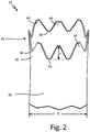
- FIG. 2 is a partial perspective view of element flow tube 12 having protrusions 42 forming tapered truncated peaks 44 and curved valleys 46.
- Element flow tube 12 includes main body 38, entrance 40, and protrusions 42 that form peaks 44 and valleys 46. Also shown in FIG. 2 is diameter D and height H.
- An upper end of main body 38 is connected to a lower end of entrance 40, such that entrance 40 makes up an upper portion of element flow tube 12.
- Protrusions 42 are positioned along an upper end of entrance 40 such that protrusions 42 extend around the entire circumference of entrance 40. In alternate embodiments, protrusions 42 extend around a portion of the circumference of entrance 40.
- Entrance 40 has at least two protrusions 42. Diameter D is a diameter of element flow tube 12.
- Protrusions 42 have height H, which is a distance between a top of a peak 44 and a bottom of a valley 46, or the peak-to-valley amplitude.
- a ratio of diameter D to height H is between about two and about six.
- FIG. 3 is a partial perspective view of an embodiment of element flow tube 12A having triangular shaped protrusions.
- Element flow tube 12A includes main body 38A, entrance 40A, and protrusions 42A that form peaks 44A and valleys 46A. Also shown in FIG. 3 is diameter D and height H.
- An upper end of main body 38A is connected to a lower end of entrance 40A, such that entrance 40A makes up an upper portion of element flow tube 12A.
- Protrusions 42A are positioned along an upper end of entrance 40A such that protrusions 42A extend around an entire circumference of entrance 40A. In alternate embodiments, protrusions 42A extend around a portion of the circumference of entrance 40A.
- Entrance 40A has at least two protrusions 42A.
- Diameter D is a diameter of element flow tube 12A.
- Protrusions 42A form a series of alternating peaks 44A and valleys 46A around entrance 40A.
- Peaks 44A may be any suitable shape, and in this embodiment, peaks 44A are triangular or V-shaped.
- Valleys 46A may be any suitable shape, and in this embodiment, valleys 46A are triangular or V-shaped.
- entrance 40A is serrated with triangular shaped protrusions 42A.
- Protrusions 42A have height H, which is a distance between a top of a peak 44A and a bottom of a valley 46A, or the peak-to-valley amplitude.
- a ratio of diameter D to height H is between about two and about six.
- FIG. 4 a partial perspective view of an embodiment of element flow tube 12B having sinusoidal shaped protrusions.
- Element flow tube 12B includes main body 38B, entrance 40B, and protrusions 42B that form peaks 44B and valleys 46B. Also shown in FIG. 4 is diameter D and height H.
- An upper end of main body 38B is connected to a lower end of entrance 40B, such that entrance 40B makes up an upper portion of element flow tube 12B.
- Protrusions 42B are positioned along an upper end of entrance 40B such that protrusions 42B extend around a circumference of entrance 40B. In alternate embodiments, protrusions 42B extend around a portion of the circumference of entrance 40B.
- Entrance 40B has at least two protrusions 42B. Diameter D is a diameter of element flow tube 12B.
- Protrusions 42B form a series of alternating peaks 44B and valleys 46B around entrance 40B.
- Peaks 44B may be any suitable shape, and in this embodiment, peaks 44B are sinusoidal or curved.
- Valleys 46B may be any suitable shape, and in this embodiment, valleys 46B are sinusoidal or curved.
- entrance 40B is scalloped with sinusoidal or curved protrusions 42B.
- Protrusions 42B have height H, which is a distance between a top of a peak 44B and a bottom of a valley 46B, or the peak-to-valley amplitude.
- a ratio of diameter D to height H is between about two and about six.
- FIG. 5 a partial perspective view of an embodiment of element flow tube 12C having rectangular shaped protrusions.
- Element flow tube 12C includes main body 38C, entrance 40C, and protrusions 42C that form peaks 44C and valleys 46C. Also shown in FIG. 5 is diameter D and height H.
- An upper end of main body 38C is connected to a lower end of entrance 40C, such that entrance 40C makes up an upper portion of element flow tube 12C.
- Protrusions 42C are positioned along an upper end of entrance 40C such that protrusions 42C extend around a circumference of entrance 40C. In alternate embodiments, protrusions 42C extend around a portion of the circumference of entrance 40C.
- Entrance 40C has at least two protrusions 42C.
- Diameter D is a diameter of element flow tube 12C.
- Protrusions 42C form a series of alternating peaks 44C and valleys 46C around entrance 40C.
- Peaks 44C may be any suitable shape, and in this embodiment, peaks 44C are rectangular shaped.
- Valleys 46C may be any suitable shape, and in this embodiment, valleys 46C are rectangular shaped.
- entrance 40C is castellated or crenellated with rectangular shaped protrusions 42C.
- Protrusions 42C have height H, which is a distance between a top of a peak 44C and a bottom of a valley 46C, or the peak-to-valley amplitude.
- a ratio of diameter D to height H is between about two and about six.
- FIGS. 2 , 3 , 4 , and 5 show embodiments of element flow tube 12 illustrating different forms protrusions 42 can take. Each of these embodiments function in a similar way and provide the same advantages or benefits as discussed in reference to FIGS. 1A and 1B .
- a total air temperature probe including a housing defining a total air temperature sensor flow passage; and a sensor assembly positioned within the total air temperature sensor flow passage, the sensor assembly including: an element flow tube, wherein an upper portion of the element flow tube is an entrance including a plurality of protrusions that extend in an upstream direction; and a sensing element within the element flow tube.
- the total air temperature probe of the preceding paragraph can optionally include, additionally and/or alternatively, any one or more of the following features, configurations and/or additional components:
- the plurality of protrusions form a plurality of peaks and a plurality of valleys.
- the protrusions are triangular shaped.
- the protrusions are curved.
- the protrusions are rectangular-shaped.
- the protrusions are tapered and truncated.
- a ratio of a diameter of the element flow tube to a peak-to-valley height of the protrusions is between about two and about six.
- the sensor assembly further comprises a flow liner positioned annularly around the element flow tube and the entrance of the element flow tube is shaped to extend into the total air temperature sensor flow passage toward an inlet scoop in the housing and beyond an upper portion of the flow liner.
- the entrance is curved to extend upstream into a curved total air temperature sensor flow passage.
- the protrusions are configured to decrease ice accretion on the entrance of the element flow tube.
- the sensing element is configured to measure total air temperature.
- a total air temperature probe including a housing including: an inlet scoop; and a total air temperature sensor flow passage downstream of the inlet scoop; and a sensor assembly positioned in the total air temperature sensor flow passage, the sensor assembly including: an annular element flow tube having an entrance comprising the upper portion of the element flow tube; and a sensing element within the element flow tube and downstream of the entrance; wherein the entrance has protrusions that form peaks and valleys around the entrance, the protrusions extending upstream into the total air temperature sensor flow passage.
- the total air temperature probe of the preceding paragraph can optionally include, additionally and/or alternatively, any one or more of the following features, configurations and/or additional components:
- a ratio of a diameter of the element flow tube to a peak-to-valley height of the protrusions is between about two and about six.
- the protrusions have a shape selected from the group consisting of: a triangular shape, a curved shape, a rectangular shape, and a tapered shape with a truncated edge.
- Protrusions extend entirely around a circumference of the entrance.
- a total air temperature probe including a housing including: an inlet scoop; an outlet; a total air temperature sensor flow passage downstream of the inlet scoop; and a flow separation bend downstream of the inlet and adjacent the total air temperature sensor flow passage; and a sensor assembly positioned in the total air temperature sensor flow passage, the sensor assembly including: an element flow tube having an entrance comprising the upper portion of the element flow tube; a sensing element within the element flow tube; and a flow liner positioned annularly around the element flow tube; wherein the entrance of the element flow tube has protrusions extending upstream into the total air temperature sensor flow passage.
- the total air temperature probe of the preceding paragraph can optionally include, additionally and/or alternatively, any one or more of the following features, configurations and/or additional components:
- the protrusions form a plurality of peaks and a plurality of valleys.
- a ratio of a diameter of the element flow tube to a peak-to-valley height of the protrusions is between about two and about six.
- the protrusions have a shape selected from the group consisting of: a triangular shape, a curved shape, a rectangular shape, and a tapered shape with a truncated edge.
- Protrusions extend entirely around a circumference of the entrance.
Landscapes
- Physics & Mathematics (AREA)
- General Physics & Mathematics (AREA)
- Measuring Temperature Or Quantity Of Heat (AREA)
- Measuring Volume Flow (AREA)
Abstract
Description
- The present disclosure relates to sensors, and in particular, to total air temperature (TAT) probes.
- TAT probes are mounted on aircraft to measure the total air temperature on the skin of the aircraft. More specifically, TAT probes cause the surrounding airflow to stagnate and then measure the temperature of the stagnated air. Often TAT probes operate in environmental conditions that may include rain, ice, ice crystals, and other particles. Such small particles can interfere with sensor passage flow and can accumulate on the sensor assembly of the TAT probe, which may result in erroneous TAT measurement.
- A total air temperature probe includes a housing defining a total air temperature sensor flow passage and a sensor assembly positioned within the total air temperature sensor flow passage. The sensor assembly includes an element flow tube, and a sensing element within the element flow tube. An upper portion of the element flow tube is an entrance including a plurality of protrusions that extend in an upstream direction.
- A total air temperature probe includes a housing, including an inlet scoop and a total air temperature sensor flow passage downstream of the inlet scoop, and a sensor assembly positioned in the total air temperature sensor flow passage. The sensor assembly includes an annular element flow tube having an entrance comprising the upper portion of the element flow tube and a sensing element within the element flow tube and downstream of the entrance. The entrance has protrusions that form peaks and valleys around the entrance, the protrusions extending upstream into the total air temperature sensor flow passage.
- A total air temperature probe includes a housing including an inlet scoop, an outlet, a total air temperature sensor flow passage downstream of the inlet scoop, and a flow separation bend between the inlet scoop and the total air temperature sensor flow passage. The total air temperature probe also includes a sensor assembly positioned in the total air temperature sensor flow passage. The sensor assembly includes an element flow tube having an entrance comprising the upper portion of the element flow tube, a sensing element within the element flow tube, and a flow liner positioned annularly around the element flow tube. The entrance of the element flow tube has protrusions extending upstream into the total air temperature sensor flow passage.
-
-
FIG. 1A is a cross-sectional view of a total air temperature (TAT) probe. -
FIG. 1B is a partial enlarged cross-sectional view of the TAT probe showing ice accretion on an element flow tube. -
FIG. 2 is a partial perspective view of the element flow tube having protrusions forming tapered truncated peaks and curved valleys. -
FIG. 3 is a partial perspective view of an embodiment of the element flow tube having triangular shaped protrusions. -
FIG. 4 a partial perspective view of an embodiment of the element flow tube having sinusoidal shaped protrusions. -
FIG. 5 a partial perspective view of an embodiment of the element flow tube having rectangular shaped protrusions. - In general, the present disclosure is a total air temperature (TAT) probe that includes an element flow tube with an entrance having protrusions extending toward an airflow. The protrusions reduce substantial ice accretion on the entrance, decreasing TAT measurement errors. As a result, the TAT probe has improved functionality in severe icing conditions.
-
FIG. 1A is a cross-sectional view ofTAT probe 10.FIG. 1B is a partial enlarged cross-sectional view ofTAT probe 10 showing accretion of ice I onelement flow tube 12.TAT probe 10 includes housing 14, mounting flange 16 (shown inFIG. 1A ), andsensor assembly 18. Housing 14 includesinlet scoop 20, outlet 22 (shown inFIG. 1A ),main airflow passage 24,flow separation bend 26, TATsensor flow passage 28, bleedholes 29, and exit ports 30 (shown inFIG. 1A ).Sensor assembly 18 includeselement flow tube 12,sensing elements 32,tip support 34, andflow liner 36.Element flow tube 12 includesmain body 38 andentrance 40.Entrance 40 includesprotrusions 42, which formpeaks 44 andvalleys 46 atentrance 40. Also shown inFIGS. 1A and1B are airflow A, particles P, and ice I (shown inFIG. 1B ). - TAT
probe 10 has housing 14 attached to mountingflange 16. Housing 14 is heated and provides structure forTAT probe 10.Mounting flange 16 mounts TATprobe 10 to an aircraft.Sensor assembly 18 is positioned within housing 14. - Inlet
scoop 20 is located near an outer end of housing 14 at a first side of housing 14.Outlet 22 is located near an outer end of housing 14 at a second side of housing 14.Main airflow passage 24 is a passageway within housing 14 that extends frominlet scoop 20 tooutlet 22.Flow separation bend 26 is a curve in housing 14 betweeninlet scoop 20 andoutlet 22 and adjacentmain airflow passage 24 and TATsensor flow passage 28.Flow separation bend 26 provides a curve of about 120 degrees betweenmain airflow passage 24 and a first end of TATsensor flow passage 28. In alternate embodiments,TAT probe 10 does not includeflow separation bend 26. In such embodiments, a curve betweenmain airflow passage 24 and the first end of TATsensor flow passage 28 may be about 90 degrees. TATsensor flow passage 28 is a passageway within housing 14 that has a first end positioned betweeninlet scoop 20 andoutlet 22 and adjacentmain airflow passage 24. The first end of TATsensor flow passage 28 is curved alongflow separation bend 26. In alternate embodiments, the first end of TATsensor flow passage 28 may be straight. Further, in alternate embodiments, the first end of TATsensor flow passage 28 may be perpendicular to mainairflow passage 24. The second end of TATsensor flow passage 28 extends into housing 14 toward mountingflange 16. TATsensor flow passage 28 is in fluid communication withmain airflow passage 24.Bleed holes 29 are passageways in housing 14 that extend frommain airflow passage 24 or TATsensor flow passage 28 through housing 14 to an exterior of housing 14.Exit ports 30 are passageways in housing 14 that extend from a second end of TATsensor flow passage 28 through housing 14 to the exterior of housing 14. The passageways ofexit ports 30 reach the exterior of housing 14 at the second side of housing 14. -
Element flow tube 12 ofsensor assembly 18 is annular and positioned within TATsensor flow passage 28 aroundsensing elements 32.Sensing elements 32 are rod-like and located withinelement flow tube 12.Sensing elements 32 may be wire wound platinum resistance devices.Sensor assembly 18 has twosensing elements 32. In alternate embodiments,sensor assembly 18 has any number ofsensing elements 32.Tip support 34 is connected to an inner surface ofelement flow tube 12 and extends toward and contacts upper ends ofsensing elements 32.Flow liner 36 is an annular and positioned aroundelement flow tube 12. As such,sensing elements 32, element flowtube 12, and flowliner 36 make up a concentric tubular assembly in TATsensor flow passage 28.Sensor assembly 18, not includingtip support 34, may be formed by additive manufacturing. -
Element flow tube 12 hasmain body 38 withentrance 40 having a lower end connected to an upper end ofmain body 38.Main body 38 is positioned around sensingelements 32 within the second end of TATsensor flow passage 28.Entrance 40 extends upstream from the upper end ofmain body 38, such thatentrance 40 makes up an upper portion ofelement flow tube 12, and into the first end of TATsensor flow passage 28. In this embodiment, TATsensor flow passage 28 is curved andentrance 40 follows the curve of TATsensor flow passage 28. In alternate embodiments,entrance 40 is not curved.Protrusions 42 are positioned along an upper end ofentrance 40. In this embodiment,protrusions 42 are positioned or extend entirely around a circumference ofentrance 40. In alternate embodiments,protrusions 42 extend around a portion of the circumference ofentrance 40.Protrusions 42 extend upstream into TATsensor flow passage 28 toward airflow A. In this embodiment,protrusions 42 extend upstream into TATsensor flow passage 28 directly towardairflow A. Entrance 40 has at least twoprotrusions 42.Protrusions 42 may be any suitable shape.Element flow tube 12 may be one unitary piece. Alternatively,main body 38 andentrance 40 ofelement flow tube 12 may be separate pieces that are welded or brazed together.Element flow tube 12 may be formed by additive manufacturing. -
Protrusions 42 form a series of alternatingpeaks 44 andvalleys 46 aroundentrance 40.Peaks 44 may be any suitable shape, and in this embodiment, peaks 44 are tapered with flat tops.Valleys 46 may be any suitable shape, and in this embodiment,valleys 46 are curved. As a result,entrance 40 is serrated with protrusions formingcurved valleys 46 and tapered truncated peaks 44. - Airflow A and particles P enter housing 14 of
TAT probe 10 throughinlet scoop 20. A portion of airflow A, along with a portion of particles P, flows throughmain airflow passage 24 and out of housing 14 throughoutlet 22. Another portion of airflow A, along with a lesser portion of particles P, flows partially throughmain airflow passage 24 and turns into TATsensor flow passage 28 alongflow separation bend 26. Airflow A curves alongflow separation bend 26 as airflow A flows into and through the first end of TATsensor flow passage 28. Some of airflow A inmain airflow passage 24 and some of airflow A in TATsensor flow passage 28 flows out of housing 14 through bleed holes 29. Airflow A remaining in TATsensor flow passage 28 flows around and intosensor assembly 18. Airflow A flows throughentrance 40 to reachsensing elements 32.Sensing elements 32 measure the total air temperature of airflow A that enterselement flow tube 12. Airflow A exits the second end of TATsensor flow passage 28 and housing 14 throughexit ports 30. -
Protrusions 42 atentrance 40 ofelement flow tube 12 extend into TATsensor flow passage 28 and come into contact with airflow A and particles P. Particles P may be water, ice crystals, or other particles P in airflow A. Particles P can flow through TATsensor flow passage 28 and accumulate on a top surface ofentrance 40 ofelement flow tube 12 where particles P can freeze to form ice I. Accretion onentrance 40 tends to tends to grow toward impinging airflow A. Ice I can obstruct and alter sensor passage flow, resulting in temperature measurement errors. -
Protrusions 42 decrease ice accretion onentrance 40 ofelement flow tube 12.Protrusions 42 reduce dimensions ofentrance 40 on which particles P can accumulate. Rather than accreting as a larger and stronger tubular shape, ice accretes on tops ofprotrusions 42 ofentrance 40 as smaller, slender rod-like growths. Such growths of ice I break off and shed at a higher rate than larger tubular growths that may form on an entrance not includingprotrusions 42. Consequently, growths of ice I shed fromprotrusions 42 before substantial flow disruption occurs. As a result, accretion of ice I does not adversely affect TAT measurement ofTAT probe 10, allowingTAT probe 10 to function better in severe icing conditions. -
FIG. 2 is a partial perspective view ofelement flow tube 12 havingprotrusions 42 forming taperedtruncated peaks 44 andcurved valleys 46.Element flow tube 12 includesmain body 38,entrance 40, andprotrusions 42 that form peaks 44 andvalleys 46. Also shown inFIG. 2 is diameter D and height H. - An upper end of
main body 38 is connected to a lower end ofentrance 40, such thatentrance 40 makes up an upper portion ofelement flow tube 12.Protrusions 42 are positioned along an upper end ofentrance 40 such thatprotrusions 42 extend around the entire circumference ofentrance 40. In alternate embodiments,protrusions 42 extend around a portion of the circumference ofentrance 40.Entrance 40 has at least twoprotrusions 42. Diameter D is a diameter ofelement flow tube 12. -
Protrusions 42 have height H, which is a distance between a top of apeak 44 and a bottom of avalley 46, or the peak-to-valley amplitude. A ratio of diameter D to height H is between about two and about six. -
FIG. 3 is a partial perspective view of an embodiment ofelement flow tube 12A having triangular shaped protrusions.Element flow tube 12A includesmain body 38A,entrance 40A, andprotrusions 42A that form peaks 44A andvalleys 46A. Also shown inFIG. 3 is diameter D and height H. - An upper end of
main body 38A is connected to a lower end ofentrance 40A, such thatentrance 40A makes up an upper portion ofelement flow tube 12A.Protrusions 42A are positioned along an upper end ofentrance 40A such thatprotrusions 42A extend around an entire circumference ofentrance 40A. In alternate embodiments,protrusions 42A extend around a portion of the circumference ofentrance 40A.Entrance 40A has at least twoprotrusions 42A. Diameter D is a diameter ofelement flow tube 12A. -
Protrusions 42A form a series of alternatingpeaks 44A andvalleys 46A aroundentrance 40A.Peaks 44A may be any suitable shape, and in this embodiment, peaks 44A are triangular or V-shaped.Valleys 46A may be any suitable shape, and in this embodiment,valleys 46A are triangular or V-shaped. As a result,entrance 40A is serrated with triangular shapedprotrusions 42A.Protrusions 42A have height H, which is a distance between a top of apeak 44A and a bottom of avalley 46A, or the peak-to-valley amplitude. A ratio of diameter D to height H is between about two and about six. -
FIG. 4 a partial perspective view of an embodiment ofelement flow tube 12B having sinusoidal shaped protrusions.Element flow tube 12B includesmain body 38B,entrance 40B, andprotrusions 42B that form peaks 44B andvalleys 46B. Also shown inFIG. 4 is diameter D and height H. - An upper end of
main body 38B is connected to a lower end ofentrance 40B, such thatentrance 40B makes up an upper portion ofelement flow tube 12B.Protrusions 42B are positioned along an upper end ofentrance 40B such thatprotrusions 42B extend around a circumference ofentrance 40B. In alternate embodiments,protrusions 42B extend around a portion of the circumference ofentrance 40B.Entrance 40B has at least twoprotrusions 42B. Diameter D is a diameter ofelement flow tube 12B. -
Protrusions 42B form a series of alternatingpeaks 44B andvalleys 46B aroundentrance 40B.Peaks 44B may be any suitable shape, and in this embodiment, peaks 44B are sinusoidal or curved.Valleys 46B may be any suitable shape, and in this embodiment,valleys 46B are sinusoidal or curved. As a result,entrance 40B is scalloped with sinusoidal orcurved protrusions 42B.Protrusions 42B have height H, which is a distance between a top of a peak 44B and a bottom of avalley 46B, or the peak-to-valley amplitude. A ratio of diameter D to height H is between about two and about six. -
FIG. 5 a partial perspective view of an embodiment ofelement flow tube 12C having rectangular shaped protrusions.Element flow tube 12C includesmain body 38C,entrance 40C, andprotrusions 42C that form peaks 44C andvalleys 46C. Also shown inFIG. 5 is diameter D and height H. - An upper end of
main body 38C is connected to a lower end ofentrance 40C, such thatentrance 40C makes up an upper portion ofelement flow tube 12C.Protrusions 42C are positioned along an upper end ofentrance 40C such thatprotrusions 42C extend around a circumference ofentrance 40C. In alternate embodiments,protrusions 42C extend around a portion of the circumference ofentrance 40C.Entrance 40C has at least twoprotrusions 42C. Diameter D is a diameter ofelement flow tube 12C. -
Protrusions 42C form a series of alternatingpeaks 44C andvalleys 46C aroundentrance 40C.Peaks 44C may be any suitable shape, and in this embodiment, peaks 44C are rectangular shaped.Valleys 46C may be any suitable shape, and in this embodiment,valleys 46C are rectangular shaped. As a result,entrance 40C is castellated or crenellated with rectangular shapedprotrusions 42C.Protrusions 42C have height H, which is a distance between a top of apeak 44C and a bottom of avalley 46C, or the peak-to-valley amplitude. A ratio of diameter D to height H is between about two and about six. -
FIGS. 2 ,3 ,4 , and5 show embodiments ofelement flow tube 12 illustratingdifferent forms protrusions 42 can take. Each of these embodiments function in a similar way and provide the same advantages or benefits as discussed in reference toFIGS. 1A and1B . - The following are non-exclusive descriptions of possible embodiments of the present invention.
- A total air temperature probe including a housing defining a total air temperature sensor flow passage; and a sensor assembly positioned within the total air temperature sensor flow passage, the sensor assembly including: an element flow tube, wherein an upper portion of the element flow tube is an entrance including a plurality of protrusions that extend in an upstream direction; and a sensing element within the element flow tube.
- The total air temperature probe of the preceding paragraph can optionally include, additionally and/or alternatively, any one or more of the following features, configurations and/or additional components:
The plurality of protrusions form a plurality of peaks and a plurality of valleys. - The protrusions are triangular shaped.
- The protrusions are curved.
- The protrusions are rectangular-shaped.
- The protrusions are tapered and truncated.
- A ratio of a diameter of the element flow tube to a peak-to-valley height of the protrusions is between about two and about six.
- The sensor assembly further comprises a flow liner positioned annularly around the element flow tube and the entrance of the element flow tube is shaped to extend into the total air temperature sensor flow passage toward an inlet scoop in the housing and beyond an upper portion of the flow liner.
- The entrance is curved to extend upstream into a curved total air temperature sensor flow passage.
- The protrusions are configured to decrease ice accretion on the entrance of the element flow tube.
- The sensing element is configured to measure total air temperature.
- A total air temperature probe including a housing including: an inlet scoop; and a total air temperature sensor flow passage downstream of the inlet scoop; and a sensor assembly positioned in the total air temperature sensor flow passage, the sensor assembly including: an annular element flow tube having an entrance comprising the upper portion of the element flow tube; and a sensing element within the element flow tube and downstream of the entrance; wherein the entrance has protrusions that form peaks and valleys around the entrance, the protrusions extending upstream into the total air temperature sensor flow passage.
- The total air temperature probe of the preceding paragraph can optionally include, additionally and/or alternatively, any one or more of the following features, configurations and/or additional components:
A ratio of a diameter of the element flow tube to a peak-to-valley height of the protrusions is between about two and about six. - The protrusions have a shape selected from the group consisting of: a triangular shape, a curved shape, a rectangular shape, and a tapered shape with a truncated edge.
- Protrusions extend entirely around a circumference of the entrance.
- A total air temperature probe including a housing including: an inlet scoop; an outlet; a total air temperature sensor flow passage downstream of the inlet scoop; and a flow separation bend downstream of the inlet and adjacent the total air temperature sensor flow passage; and a sensor assembly positioned in the total air temperature sensor flow passage, the sensor assembly including: an element flow tube having an entrance comprising the upper portion of the element flow tube; a sensing element within the element flow tube; and a flow liner positioned annularly around the element flow tube; wherein the entrance of the element flow tube has protrusions extending upstream into the total air temperature sensor flow passage.
- The total air temperature probe of the preceding paragraph can optionally include, additionally and/or alternatively, any one or more of the following features, configurations and/or additional components:
The protrusions form a plurality of peaks and a plurality of valleys. - A ratio of a diameter of the element flow tube to a peak-to-valley height of the protrusions is between about two and about six.
- The protrusions have a shape selected from the group consisting of: a triangular shape, a curved shape, a rectangular shape, and a tapered shape with a truncated edge.
- Protrusions extend entirely around a circumference of the entrance.
- While the invention has been described with reference to an exemplary embodiment(s), it will be understood by those skilled in the art that various changes may be made and equivalents may be substituted for elements thereof without departing from the scope of the invention. In addition, many modifications may be made to adapt a particular situation or material to the teachings of the invention without departing from the essential scope thereof. Therefore, it is intended that the invention not be limited to the particular embodiment(s) disclosed, but that the invention will include all embodiments falling within the scope of the appended claims.
Claims (14)
- A total air temperature probe comprising:a housing defining a total air temperature sensor flow passage; anda sensor assembly positioned within the total air temperature sensor flow passage, the sensor assembly including:an element flow tube, wherein an upper portion of the element flow tube is an entrance including a plurality of protrusions that extend in an upstream direction; anda sensing element within the element flow tube.
- The total air temperature probe of claim 1, wherein the plurality of protrusions form a plurality of peaks and a plurality of valleys.
- The total air temperature probe of claim 2, wherein the protrusions are triangular shaped.
- The total air temperature probe of claim 2, wherein the protrusions are curved.
- The total air temperature probe of claim 2, wherein the protrusions are rectangular shaped.
- The total air temperature probe of claim 2, wherein the protrusions are tapered and truncated.
- The total air temperature probe of any of claims 2 to 6, wherein a ratio of a diameter of the element flow tube to a peak-to-valley height of the protrusions is between about two and about six.
- The total air temperature probe of any preceding claim, wherein the sensor assembly further comprises a flow liner positioned annularly around the element flow tube and the entrance of the element flow tube is shaped to extend into the total air temperature sensor flow passage toward an inlet scoop in the housing and beyond an upper portion of the flow liner.
- The total air temperature probe of any preceding claim, wherein the entrance is curved to extend upstream into a curved total air temperature sensor flow passage.
- The total air temperature probe of any preceding claim, wherein the protrusions are configured to decrease ice accretion on the entrance of the element flow tube.
- The total air temperature probe of any preceding claim, wherein the sensing element is configured to measure total air temperature.
- A total air temperature probe as claimed in any preceding claim,the housing including:an inlet scoop; andthe total air temperature sensor flow passage downstream of the inlet scoop,the element flow tube being annular, andthe sensing element within the element flow tube being downstream of the entrance,wherein the protrusions form peaks and valleys around the entrance, the protrusions extending upstream into the total air temperature sensor flow passage.
- The total air temperature probe of claim 12, wherein protrusions extend entirely around a circumference of the entrance.
- A total air temperature probe as claimed in any preceding claim,the housing including:an inlet scoop;an outlet;the total air temperature sensor flow passage downstream of the inlet scoop; anda flow separation bend downstream of the inlet scoop and adjacent the total air temperature sensor flow passage,the total air temperature probe further including:
a flow liner positioned annularly around the element flow tube,wherein the entrance of the element flow tube has the plurality of protrusions
extending upstream into the total air temperature sensor flow passage.
Applications Claiming Priority (1)
| Application Number | Priority Date | Filing Date | Title |
|---|---|---|---|
| US15/617,768 US10422702B2 (en) | 2017-06-08 | 2017-06-08 | Total air temperature probe with reduced icing sensor flow passage geometry |
Publications (2)
| Publication Number | Publication Date |
|---|---|
| EP3413025A1 true EP3413025A1 (en) | 2018-12-12 |
| EP3413025B1 EP3413025B1 (en) | 2021-04-14 |
Family
ID=62492440
Family Applications (1)
| Application Number | Title | Priority Date | Filing Date |
|---|---|---|---|
| EP18175038.1A Active EP3413025B1 (en) | 2017-06-08 | 2018-05-30 | Total air temperature probe with reduced icing sensor flow passage geometry |
Country Status (2)
| Country | Link |
|---|---|
| US (1) | US10422702B2 (en) |
| EP (1) | EP3413025B1 (en) |
Cited By (8)
| Publication number | Priority date | Publication date | Assignee | Title |
|---|---|---|---|---|
| EP3508425A1 (en) * | 2018-01-05 | 2019-07-10 | Rosemount Aerospace Inc. | Features to prevent ice accumulation on heated faceplate |
| EP3581901A1 (en) * | 2018-06-15 | 2019-12-18 | Rosemount Aerospace Inc. | Total air temperature probe with concave flow path transitions to outlet |
| US10877062B2 (en) | 2018-05-09 | 2020-12-29 | Rosemount Aerospace Inc. | Aft-located heated ramp for ice and water management of angle of attack sensors |
| US10928416B2 (en) | 2018-05-09 | 2021-02-23 | Rosemount Aerospace Inc. | Dual heated ramp for ice and water management in angle of attack sensors |
| US11162970B2 (en) | 2019-06-17 | 2021-11-02 | Rosemount Aerospace Inc. | Angle of attack sensor |
| US11181545B2 (en) | 2017-08-17 | 2021-11-23 | Rosemount Aerospace Inc. | Angle of attack sensor with thermal enhancement |
| US11649057B2 (en) | 2019-12-13 | 2023-05-16 | Rosemount Aerospace Inc. | Static plate heating arrangement |
| US12339294B2 (en) | 2020-02-25 | 2025-06-24 | Rosemount Aerospace Inc. | Angle of attack sensor vane geometry |
Families Citing this family (4)
| Publication number | Priority date | Publication date | Assignee | Title |
|---|---|---|---|---|
| US11913926B2 (en) | 2019-11-04 | 2024-02-27 | Honeywell Analytics Inc. | Multi-sensor gas detector |
| CN119618391B (en) * | 2023-09-14 | 2025-11-25 | 中国航发商用航空发动机有限责任公司 | An aircraft total temperature sensor housing and total temperature sensor assembly |
| USD1110868S1 (en) * | 2024-02-09 | 2026-02-03 | Rosemount Aerospace Inc. | Aircraft total air temperature sensor |
| USD1110867S1 (en) * | 2024-02-09 | 2026-02-03 | Rosemount Aerospace Inc. | Aircraft total air temperature sensor |
Citations (3)
| Publication number | Priority date | Publication date | Assignee | Title |
|---|---|---|---|---|
| US20060056489A1 (en) * | 2002-06-14 | 2006-03-16 | Marc Bernard | De-iced total air temperature sensor |
| EP2930492A2 (en) * | 2014-04-11 | 2015-10-14 | Deutscher Wetterdienst | Water vapour measuring device and probe |
| US20160238456A1 (en) * | 2015-02-12 | 2016-08-18 | Rosemount Aerospace Inc. | Air temperature sensor and fabrication |
Family Cites Families (20)
| Publication number | Priority date | Publication date | Assignee | Title |
|---|---|---|---|---|
| US2970475A (en) | 1956-10-08 | 1961-02-07 | Rosemount Eng Co Ltd | Gas temperature probe |
| US5302026A (en) * | 1992-07-16 | 1994-04-12 | Rosemount, Inc. | Temperature probe with fast response time |
| US5653538A (en) | 1995-06-07 | 1997-08-05 | Rosemount Aerospace Inc. | Total temperature probe |
| US5752674A (en) | 1996-08-21 | 1998-05-19 | General Electric Company | Sensor ice shield |
| FR2802647B1 (en) | 1999-12-17 | 2002-03-01 | Thomson Csf Sextant | PROBE FOR AIRCRAFT |
| FR2808874B1 (en) | 2000-05-15 | 2002-07-26 | Auxitrol Sa | SENSOR FOR MEASUREMENT OF PHYSICAL PARAMETERS ON A FLUID FLOW AND IN PARTICULAR AIR TEMPERATURE SENSOR |
| US6609825B2 (en) | 2001-09-21 | 2003-08-26 | Rosemount Aerospace Inc. | Total air temperature probe providing improved anti-icing performance and reduced deicing heater error |
| FR2833347B1 (en) | 2001-12-11 | 2004-02-27 | Thales Sa | MULTIFUNCTIONAL PROBE FOR AIRCRAFT |
| FR2859787B1 (en) * | 2003-09-16 | 2006-01-20 | Thales Sa | DEVICE AND METHOD FOR DETERMINING THE TOTAL TEMPERATURE FOR AN AIRCRAFT |
| US6974250B2 (en) * | 2004-04-15 | 2005-12-13 | Rosemount Aerospace Inc. | Temperature sensor with controlled thermal offset for determining static temperature |
| US7191643B2 (en) | 2004-06-03 | 2007-03-20 | University Corporation For Atmospheric Research | Sensor system to distinguish frozen and non-frozen liquid particulates |
| US7357572B2 (en) | 2005-09-20 | 2008-04-15 | Rosemount Aerospace Inc. | Total air temperature probe having improved deicing heater error performance |
| JP2010513939A (en) * | 2006-12-19 | 2010-04-30 | ローズマウント・エアロスペース・インコーポレーテツド | Integrated global atmospheric temperature probe and electronics |
| US7828477B2 (en) | 2007-05-14 | 2010-11-09 | Rosemount Aerospace Inc. | Aspirated enhanced total air temperature probe |
| GB2455728A (en) | 2007-12-18 | 2009-06-24 | Weston Aerospace Ltd | Air temperature sensing on aircraft |
| FR2956737B1 (en) | 2010-02-25 | 2012-03-30 | Auxitrol Sa | ICE BREAKER PROBE FOR MEASURING THE TOTAL AIR TEMPERATURE |
| US9658117B2 (en) | 2012-08-18 | 2017-05-23 | Rosemount Aerospace Inc. | Total air temperature probes for reducing deicing heater error |
| US9829395B2 (en) * | 2012-12-13 | 2017-11-28 | Rosemount Aerospace Inc. | Air temperature sensor arrangement for a vehicle and method of measuring air temperature |
| US20160102562A1 (en) | 2013-05-21 | 2016-04-14 | Siemens Energy, Inc. | Cooling arrangement for gas turbine blade platform |
| US10203253B2 (en) | 2016-02-10 | 2019-02-12 | Rosemount Aerospace Inc. | Total air temperature probe with efficient particle pass through |
-
2017
- 2017-06-08 US US15/617,768 patent/US10422702B2/en active Active
-
2018
- 2018-05-30 EP EP18175038.1A patent/EP3413025B1/en active Active
Patent Citations (3)
| Publication number | Priority date | Publication date | Assignee | Title |
|---|---|---|---|---|
| US20060056489A1 (en) * | 2002-06-14 | 2006-03-16 | Marc Bernard | De-iced total air temperature sensor |
| EP2930492A2 (en) * | 2014-04-11 | 2015-10-14 | Deutscher Wetterdienst | Water vapour measuring device and probe |
| US20160238456A1 (en) * | 2015-02-12 | 2016-08-18 | Rosemount Aerospace Inc. | Air temperature sensor and fabrication |
Cited By (13)
| Publication number | Priority date | Publication date | Assignee | Title |
|---|---|---|---|---|
| US11768219B2 (en) | 2017-08-17 | 2023-09-26 | Rosemount Aerospace Inc. | Angle of attack sensor with thermal enhancement |
| US11181545B2 (en) | 2017-08-17 | 2021-11-23 | Rosemount Aerospace Inc. | Angle of attack sensor with thermal enhancement |
| US11142323B2 (en) | 2018-01-05 | 2021-10-12 | Rosemount Aerospace Inc. | Features to prevent ice accumulation on heated faceplate |
| EP3508425A1 (en) * | 2018-01-05 | 2019-07-10 | Rosemount Aerospace Inc. | Features to prevent ice accumulation on heated faceplate |
| US10877062B2 (en) | 2018-05-09 | 2020-12-29 | Rosemount Aerospace Inc. | Aft-located heated ramp for ice and water management of angle of attack sensors |
| US10928416B2 (en) | 2018-05-09 | 2021-02-23 | Rosemount Aerospace Inc. | Dual heated ramp for ice and water management in angle of attack sensors |
| US10852203B2 (en) | 2018-06-15 | 2020-12-01 | Rosemount Aerospace Inc. | Total air temperature probe with concave flow path transitions to outlet |
| EP3581901A1 (en) * | 2018-06-15 | 2019-12-18 | Rosemount Aerospace Inc. | Total air temperature probe with concave flow path transitions to outlet |
| US11162970B2 (en) | 2019-06-17 | 2021-11-02 | Rosemount Aerospace Inc. | Angle of attack sensor |
| US11649057B2 (en) | 2019-12-13 | 2023-05-16 | Rosemount Aerospace Inc. | Static plate heating arrangement |
| US12339294B2 (en) | 2020-02-25 | 2025-06-24 | Rosemount Aerospace Inc. | Angle of attack sensor vane geometry |
| US12345731B2 (en) | 2020-02-25 | 2025-07-01 | Rosemount Aerospace Inc. | Angle of attack sensor with integral bearing support cage |
| US12360134B2 (en) | 2020-02-25 | 2025-07-15 | Rosemount Aerospace Inc. | Angle of attack sensor with sloped faceplate |
Also Published As
| Publication number | Publication date |
|---|---|
| US20180356293A1 (en) | 2018-12-13 |
| EP3413025B1 (en) | 2021-04-14 |
| US10422702B2 (en) | 2019-09-24 |
Similar Documents
| Publication | Publication Date | Title |
|---|---|---|
| US10422702B2 (en) | Total air temperature probe with reduced icing sensor flow passage geometry | |
| US6840672B2 (en) | Total air temperature probe providing improved anti-icing performance and reduced deicing heater error | |
| US4991976A (en) | Temperature sensor probe apparatus and method for improving time response | |
| EP2866011B1 (en) | Temperature sensors | |
| US9488534B2 (en) | Supercritical total air temperature sensors | |
| EP3173797B1 (en) | Air data probe with double helical coil heater cable | |
| US10612984B2 (en) | Sensor aspiration utilizing hoop airflow induction | |
| US20130061964A1 (en) | Device for multipoint acquisition/distribution of fluid, in particular probe for tapping pressure in a turbomachine air inlet | |
| CA2956199C (en) | Hybrid material pitot tube | |
| EP2700952A1 (en) | Moisture resistant air data probes | |
| CN105987765A (en) | Air Data Probe | |
| CN107917793B (en) | Multirow pressure measurement harrow device for experiments | |
| EP3581901B1 (en) | Total air temperature probe with concave flow path transitions to outlet | |
| EP3683584A1 (en) | Pitot tube | |
| US8413501B2 (en) | Wake measurement probe | |
| US20190210734A1 (en) | Features to prevent ice accumulation on heated faceplate | |
| EP3205582A1 (en) | Total air temperature probe with efficient particle pass through | |
| CN110466779B (en) | Ice crystal detector | |
| JP6110047B1 (en) | Sensor device | |
| CN110466778B (en) | Icing detector | |
| JP6043024B2 (en) | Sensor device | |
| EP4458679A1 (en) | Airflow modifying device | |
| JP2021517645A (en) | Sensor configuration | |
| JP2026515972A (en) | Airflow modification device | |
| SE520901C2 (en) | emission electrode |
Legal Events
| Date | Code | Title | Description |
|---|---|---|---|
| PUAI | Public reference made under article 153(3) epc to a published international application that has entered the european phase |
Free format text: ORIGINAL CODE: 0009012 |
|
| STAA | Information on the status of an ep patent application or granted ep patent |
Free format text: STATUS: THE APPLICATION HAS BEEN PUBLISHED |
|
| AK | Designated contracting states |
Kind code of ref document: A1 Designated state(s): AL AT BE BG CH CY CZ DE DK EE ES FI FR GB GR HR HU IE IS IT LI LT LU LV MC MK MT NL NO PL PT RO RS SE SI SK SM TR |
|
| AX | Request for extension of the european patent |
Extension state: BA ME |
|
| STAA | Information on the status of an ep patent application or granted ep patent |
Free format text: STATUS: REQUEST FOR EXAMINATION WAS MADE |
|
| 17P | Request for examination filed |
Effective date: 20190612 |
|
| RBV | Designated contracting states (corrected) |
Designated state(s): AL AT BE BG CH CY CZ DE DK EE ES FI FR GB GR HR HU IE IS IT LI LT LU LV MC MK MT NL NO PL PT RO RS SE SI SK SM TR |
|
| GRAP | Despatch of communication of intention to grant a patent |
Free format text: ORIGINAL CODE: EPIDOSNIGR1 |
|
| STAA | Information on the status of an ep patent application or granted ep patent |
Free format text: STATUS: GRANT OF PATENT IS INTENDED |
|
| INTG | Intention to grant announced |
Effective date: 20200422 |
|
| GRAJ | Information related to disapproval of communication of intention to grant by the applicant or resumption of examination proceedings by the epo deleted |
Free format text: ORIGINAL CODE: EPIDOSDIGR1 |
|
| STAA | Information on the status of an ep patent application or granted ep patent |
Free format text: STATUS: REQUEST FOR EXAMINATION WAS MADE |
|
| INTC | Intention to grant announced (deleted) | ||
| GRAP | Despatch of communication of intention to grant a patent |
Free format text: ORIGINAL CODE: EPIDOSNIGR1 |
|
| STAA | Information on the status of an ep patent application or granted ep patent |
Free format text: STATUS: GRANT OF PATENT IS INTENDED |
|
| INTG | Intention to grant announced |
Effective date: 20201027 |
|
| GRAS | Grant fee paid |
Free format text: ORIGINAL CODE: EPIDOSNIGR3 |
|
| GRAA | (expected) grant |
Free format text: ORIGINAL CODE: 0009210 |
|
| STAA | Information on the status of an ep patent application or granted ep patent |
Free format text: STATUS: THE PATENT HAS BEEN GRANTED |
|
| AK | Designated contracting states |
Kind code of ref document: B1 Designated state(s): AL AT BE BG CH CY CZ DE DK EE ES FI FR GB GR HR HU IE IS IT LI LT LU LV MC MK MT NL NO PL PT RO RS SE SI SK SM TR |
|
| REG | Reference to a national code |
Ref country code: GB Ref legal event code: FG4D |
|
| REG | Reference to a national code |
Ref country code: CH Ref legal event code: EP |
|
| REG | Reference to a national code |
Ref country code: DE Ref legal event code: R096 Ref document number: 602018015413 Country of ref document: DE |
|
| REG | Reference to a national code |
Ref country code: IE Ref legal event code: FG4D |
|
| REG | Reference to a national code |
Ref country code: AT Ref legal event code: REF Ref document number: 1382834 Country of ref document: AT Kind code of ref document: T Effective date: 20210515 |
|
| REG | Reference to a national code |
Ref country code: LT Ref legal event code: MG9D |
|
| REG | Reference to a national code |
Ref country code: AT Ref legal event code: MK05 Ref document number: 1382834 Country of ref document: AT Kind code of ref document: T Effective date: 20210414 |
|
| REG | Reference to a national code |
Ref country code: NL Ref legal event code: MP Effective date: 20210414 |
|
| PG25 | Lapsed in a contracting state [announced via postgrant information from national office to epo] |
Ref country code: FI Free format text: LAPSE BECAUSE OF FAILURE TO SUBMIT A TRANSLATION OF THE DESCRIPTION OR TO PAY THE FEE WITHIN THE PRESCRIBED TIME-LIMIT Effective date: 20210414 Ref country code: HR Free format text: LAPSE BECAUSE OF FAILURE TO SUBMIT A TRANSLATION OF THE DESCRIPTION OR TO PAY THE FEE WITHIN THE PRESCRIBED TIME-LIMIT Effective date: 20210414 Ref country code: LT Free format text: LAPSE BECAUSE OF FAILURE TO SUBMIT A TRANSLATION OF THE DESCRIPTION OR TO PAY THE FEE WITHIN THE PRESCRIBED TIME-LIMIT Effective date: 20210414 Ref country code: NL Free format text: LAPSE BECAUSE OF FAILURE TO SUBMIT A TRANSLATION OF THE DESCRIPTION OR TO PAY THE FEE WITHIN THE PRESCRIBED TIME-LIMIT Effective date: 20210414 Ref country code: BG Free format text: LAPSE BECAUSE OF FAILURE TO SUBMIT A TRANSLATION OF THE DESCRIPTION OR TO PAY THE FEE WITHIN THE PRESCRIBED TIME-LIMIT Effective date: 20210714 Ref country code: AT Free format text: LAPSE BECAUSE OF FAILURE TO SUBMIT A TRANSLATION OF THE DESCRIPTION OR TO PAY THE FEE WITHIN THE PRESCRIBED TIME-LIMIT Effective date: 20210414 |
|
| PG25 | Lapsed in a contracting state [announced via postgrant information from national office to epo] |
Ref country code: IS Free format text: LAPSE BECAUSE OF FAILURE TO SUBMIT A TRANSLATION OF THE DESCRIPTION OR TO PAY THE FEE WITHIN THE PRESCRIBED TIME-LIMIT Effective date: 20210814 Ref country code: GR Free format text: LAPSE BECAUSE OF FAILURE TO SUBMIT A TRANSLATION OF THE DESCRIPTION OR TO PAY THE FEE WITHIN THE PRESCRIBED TIME-LIMIT Effective date: 20210715 Ref country code: SE Free format text: LAPSE BECAUSE OF FAILURE TO SUBMIT A TRANSLATION OF THE DESCRIPTION OR TO PAY THE FEE WITHIN THE PRESCRIBED TIME-LIMIT Effective date: 20210414 Ref country code: RS Free format text: LAPSE BECAUSE OF FAILURE TO SUBMIT A TRANSLATION OF THE DESCRIPTION OR TO PAY THE FEE WITHIN THE PRESCRIBED TIME-LIMIT Effective date: 20210414 Ref country code: NO Free format text: LAPSE BECAUSE OF FAILURE TO SUBMIT A TRANSLATION OF THE DESCRIPTION OR TO PAY THE FEE WITHIN THE PRESCRIBED TIME-LIMIT Effective date: 20210714 Ref country code: PL Free format text: LAPSE BECAUSE OF FAILURE TO SUBMIT A TRANSLATION OF THE DESCRIPTION OR TO PAY THE FEE WITHIN THE PRESCRIBED TIME-LIMIT Effective date: 20210414 Ref country code: LV Free format text: LAPSE BECAUSE OF FAILURE TO SUBMIT A TRANSLATION OF THE DESCRIPTION OR TO PAY THE FEE WITHIN THE PRESCRIBED TIME-LIMIT Effective date: 20210414 Ref country code: PT Free format text: LAPSE BECAUSE OF FAILURE TO SUBMIT A TRANSLATION OF THE DESCRIPTION OR TO PAY THE FEE WITHIN THE PRESCRIBED TIME-LIMIT Effective date: 20210816 |
|
| REG | Reference to a national code |
Ref country code: CH Ref legal event code: PL |
|
| REG | Reference to a national code |
Ref country code: DE Ref legal event code: R097 Ref document number: 602018015413 Country of ref document: DE |
|
| PG25 | Lapsed in a contracting state [announced via postgrant information from national office to epo] |
Ref country code: LI Free format text: LAPSE BECAUSE OF NON-PAYMENT OF DUE FEES Effective date: 20210531 Ref country code: LU Free format text: LAPSE BECAUSE OF NON-PAYMENT OF DUE FEES Effective date: 20210530 Ref country code: MC Free format text: LAPSE BECAUSE OF FAILURE TO SUBMIT A TRANSLATION OF THE DESCRIPTION OR TO PAY THE FEE WITHIN THE PRESCRIBED TIME-LIMIT Effective date: 20210414 Ref country code: DK Free format text: LAPSE BECAUSE OF FAILURE TO SUBMIT A TRANSLATION OF THE DESCRIPTION OR TO PAY THE FEE WITHIN THE PRESCRIBED TIME-LIMIT Effective date: 20210414 Ref country code: CZ Free format text: LAPSE BECAUSE OF FAILURE TO SUBMIT A TRANSLATION OF THE DESCRIPTION OR TO PAY THE FEE WITHIN THE PRESCRIBED TIME-LIMIT Effective date: 20210414 Ref country code: CH Free format text: LAPSE BECAUSE OF NON-PAYMENT OF DUE FEES Effective date: 20210531 Ref country code: RO Free format text: LAPSE BECAUSE OF FAILURE TO SUBMIT A TRANSLATION OF THE DESCRIPTION OR TO PAY THE FEE WITHIN THE PRESCRIBED TIME-LIMIT Effective date: 20210414 Ref country code: SK Free format text: LAPSE BECAUSE OF FAILURE TO SUBMIT A TRANSLATION OF THE DESCRIPTION OR TO PAY THE FEE WITHIN THE PRESCRIBED TIME-LIMIT Effective date: 20210414 Ref country code: SM Free format text: LAPSE BECAUSE OF FAILURE TO SUBMIT A TRANSLATION OF THE DESCRIPTION OR TO PAY THE FEE WITHIN THE PRESCRIBED TIME-LIMIT Effective date: 20210414 Ref country code: EE Free format text: LAPSE BECAUSE OF FAILURE TO SUBMIT A TRANSLATION OF THE DESCRIPTION OR TO PAY THE FEE WITHIN THE PRESCRIBED TIME-LIMIT Effective date: 20210414 Ref country code: ES Free format text: LAPSE BECAUSE OF FAILURE TO SUBMIT A TRANSLATION OF THE DESCRIPTION OR TO PAY THE FEE WITHIN THE PRESCRIBED TIME-LIMIT Effective date: 20210414 |
|
| REG | Reference to a national code |
Ref country code: BE Ref legal event code: MM Effective date: 20210531 |
|
| PLBE | No opposition filed within time limit |
Free format text: ORIGINAL CODE: 0009261 |
|
| STAA | Information on the status of an ep patent application or granted ep patent |
Free format text: STATUS: NO OPPOSITION FILED WITHIN TIME LIMIT |
|
| 26N | No opposition filed |
Effective date: 20220117 |
|
| PG25 | Lapsed in a contracting state [announced via postgrant information from national office to epo] |
Ref country code: IE Free format text: LAPSE BECAUSE OF NON-PAYMENT OF DUE FEES Effective date: 20210530 |
|
| PG25 | Lapsed in a contracting state [announced via postgrant information from national office to epo] |
Ref country code: IS Free format text: LAPSE BECAUSE OF FAILURE TO SUBMIT A TRANSLATION OF THE DESCRIPTION OR TO PAY THE FEE WITHIN THE PRESCRIBED TIME-LIMIT Effective date: 20210814 Ref country code: AL Free format text: LAPSE BECAUSE OF FAILURE TO SUBMIT A TRANSLATION OF THE DESCRIPTION OR TO PAY THE FEE WITHIN THE PRESCRIBED TIME-LIMIT Effective date: 20210414 |
|
| PG25 | Lapsed in a contracting state [announced via postgrant information from national office to epo] |
Ref country code: IT Free format text: LAPSE BECAUSE OF FAILURE TO SUBMIT A TRANSLATION OF THE DESCRIPTION OR TO PAY THE FEE WITHIN THE PRESCRIBED TIME-LIMIT Effective date: 20210414 Ref country code: BE Free format text: LAPSE BECAUSE OF NON-PAYMENT OF DUE FEES Effective date: 20210531 |
|
| PG25 | Lapsed in a contracting state [announced via postgrant information from national office to epo] |
Ref country code: CY Free format text: LAPSE BECAUSE OF FAILURE TO SUBMIT A TRANSLATION OF THE DESCRIPTION OR TO PAY THE FEE WITHIN THE PRESCRIBED TIME-LIMIT Effective date: 20210414 |
|
| PG25 | Lapsed in a contracting state [announced via postgrant information from national office to epo] |
Ref country code: HU Free format text: LAPSE BECAUSE OF FAILURE TO SUBMIT A TRANSLATION OF THE DESCRIPTION OR TO PAY THE FEE WITHIN THE PRESCRIBED TIME-LIMIT; INVALID AB INITIO Effective date: 20180530 |
|
| PG25 | Lapsed in a contracting state [announced via postgrant information from national office to epo] |
Ref country code: MK Free format text: LAPSE BECAUSE OF FAILURE TO SUBMIT A TRANSLATION OF THE DESCRIPTION OR TO PAY THE FEE WITHIN THE PRESCRIBED TIME-LIMIT Effective date: 20210414 |
|
| PG25 | Lapsed in a contracting state [announced via postgrant information from national office to epo] |
Ref country code: TR Free format text: LAPSE BECAUSE OF FAILURE TO SUBMIT A TRANSLATION OF THE DESCRIPTION OR TO PAY THE FEE WITHIN THE PRESCRIBED TIME-LIMIT Effective date: 20210414 |
|
| PG25 | Lapsed in a contracting state [announced via postgrant information from national office to epo] |
Ref country code: MT Free format text: LAPSE BECAUSE OF FAILURE TO SUBMIT A TRANSLATION OF THE DESCRIPTION OR TO PAY THE FEE WITHIN THE PRESCRIBED TIME-LIMIT Effective date: 20210414 |
|
| PGFP | Annual fee paid to national office [announced via postgrant information from national office to epo] |
Ref country code: DE Payment date: 20250423 Year of fee payment: 8 |
|
| PGFP | Annual fee paid to national office [announced via postgrant information from national office to epo] |
Ref country code: GB Payment date: 20250423 Year of fee payment: 8 |
|
| PGFP | Annual fee paid to national office [announced via postgrant information from national office to epo] |
Ref country code: FR Payment date: 20250423 Year of fee payment: 8 |
|
| P01 | Opt-out of the competence of the unified patent court (upc) registered |
Free format text: CASE NUMBER: UPC_APP_0017153_3413025/2025 Effective date: 20251211 |