EP3412950A1 - Marine hose - Google Patents
Marine hose Download PDFInfo
- Publication number
- EP3412950A1 EP3412950A1 EP17747199.2A EP17747199A EP3412950A1 EP 3412950 A1 EP3412950 A1 EP 3412950A1 EP 17747199 A EP17747199 A EP 17747199A EP 3412950 A1 EP3412950 A1 EP 3412950A1
- Authority
- EP
- European Patent Office
- Prior art keywords
- layer
- rubber
- surface layer
- hose
- irm
- Prior art date
- Legal status (The legal status is an assumption and is not a legal conclusion. Google has not performed a legal analysis and makes no representation as to the accuracy of the status listed.)
- Withdrawn
Links
- 239000010410 layer Substances 0.000 claims abstract description 93
- 239000002344 surface layer Substances 0.000 claims abstract description 64
- 238000003780 insertion Methods 0.000 claims abstract description 13
- 230000037431 insertion Effects 0.000 claims abstract description 13
- 238000010998 test method Methods 0.000 claims abstract description 9
- 238000007654 immersion Methods 0.000 claims abstract description 7
- 238000000034 method Methods 0.000 claims abstract description 6
- 230000000704 physical effect Effects 0.000 claims abstract description 5
- 230000003014 reinforcing effect Effects 0.000 claims description 16
- 239000003921 oil Substances 0.000 description 28
- 210000002445 nipple Anatomy 0.000 description 14
- 239000012530 fluid Substances 0.000 description 9
- 238000005452 bending Methods 0.000 description 6
- 239000010779 crude oil Substances 0.000 description 4
- 238000010586 diagram Methods 0.000 description 3
- 230000000694 effects Effects 0.000 description 2
- 239000000463 material Substances 0.000 description 2
- 239000011347 resin Substances 0.000 description 2
- 229920005989 resin Polymers 0.000 description 2
- 230000008961 swelling Effects 0.000 description 2
- NLHHRLWOUZZQLW-UHFFFAOYSA-N Acrylonitrile Chemical compound C=CC#N NLHHRLWOUZZQLW-UHFFFAOYSA-N 0.000 description 1
- 239000011248 coating agent Substances 0.000 description 1
- 238000000576 coating method Methods 0.000 description 1
- 238000005336 cracking Methods 0.000 description 1
- 230000007423 decrease Effects 0.000 description 1
- 238000007667 floating Methods 0.000 description 1
- 238000004519 manufacturing process Methods 0.000 description 1
- 238000005259 measurement Methods 0.000 description 1
- 239000002184 metal Substances 0.000 description 1
- 230000000116 mitigating effect Effects 0.000 description 1
- 238000011084 recovery Methods 0.000 description 1
- 230000032258 transport Effects 0.000 description 1
- 238000004804 winding Methods 0.000 description 1
Images

Classifications
-
- F—MECHANICAL ENGINEERING; LIGHTING; HEATING; WEAPONS; BLASTING
- F16—ENGINEERING ELEMENTS AND UNITS; GENERAL MEASURES FOR PRODUCING AND MAINTAINING EFFECTIVE FUNCTIONING OF MACHINES OR INSTALLATIONS; THERMAL INSULATION IN GENERAL
- F16L—PIPES; JOINTS OR FITTINGS FOR PIPES; SUPPORTS FOR PIPES, CABLES OR PROTECTIVE TUBING; MEANS FOR THERMAL INSULATION IN GENERAL
- F16L11/00—Hoses, i.e. flexible pipes
- F16L11/04—Hoses, i.e. flexible pipes made of rubber or flexible plastics
- F16L11/08—Hoses, i.e. flexible pipes made of rubber or flexible plastics with reinforcements embedded in the wall
- F16L11/088—Hoses, i.e. flexible pipes made of rubber or flexible plastics with reinforcements embedded in the wall comprising a combination of one or more layers of a helically wound cord or wire with one or more braided layers
-
- F—MECHANICAL ENGINEERING; LIGHTING; HEATING; WEAPONS; BLASTING
- F16—ENGINEERING ELEMENTS AND UNITS; GENERAL MEASURES FOR PRODUCING AND MAINTAINING EFFECTIVE FUNCTIONING OF MACHINES OR INSTALLATIONS; THERMAL INSULATION IN GENERAL
- F16L—PIPES; JOINTS OR FITTINGS FOR PIPES; SUPPORTS FOR PIPES, CABLES OR PROTECTIVE TUBING; MEANS FOR THERMAL INSULATION IN GENERAL
- F16L33/00—Arrangements for connecting hoses to rigid members; Rigid hose-connectors, i.e. single members engaging both hoses
- F16L33/01—Arrangements for connecting hoses to rigid members; Rigid hose-connectors, i.e. single members engaging both hoses specially adapted for hoses having a multi-layer wall
-
- F—MECHANICAL ENGINEERING; LIGHTING; HEATING; WEAPONS; BLASTING
- F16—ENGINEERING ELEMENTS AND UNITS; GENERAL MEASURES FOR PRODUCING AND MAINTAINING EFFECTIVE FUNCTIONING OF MACHINES OR INSTALLATIONS; THERMAL INSULATION IN GENERAL
- F16L—PIPES; JOINTS OR FITTINGS FOR PIPES; SUPPORTS FOR PIPES, CABLES OR PROTECTIVE TUBING; MEANS FOR THERMAL INSULATION IN GENERAL
- F16L33/00—Arrangements for connecting hoses to rigid members; Rigid hose-connectors, i.e. single members engaging both hoses
- F16L33/28—Arrangements for connecting hoses to rigid members; Rigid hose-connectors, i.e. single members engaging both hoses for hoses with one end terminating in a radial flange or collar
-
- F—MECHANICAL ENGINEERING; LIGHTING; HEATING; WEAPONS; BLASTING
- F16—ENGINEERING ELEMENTS AND UNITS; GENERAL MEASURES FOR PRODUCING AND MAINTAINING EFFECTIVE FUNCTIONING OF MACHINES OR INSTALLATIONS; THERMAL INSULATION IN GENERAL
- F16L—PIPES; JOINTS OR FITTINGS FOR PIPES; SUPPORTS FOR PIPES, CABLES OR PROTECTIVE TUBING; MEANS FOR THERMAL INSULATION IN GENERAL
- F16L11/00—Hoses, i.e. flexible pipes
- F16L11/04—Hoses, i.e. flexible pipes made of rubber or flexible plastics
- F16L11/12—Hoses, i.e. flexible pipes made of rubber or flexible plastics with arrangements for particular purposes, e.g. specially profiled, with protecting layer, heated, electrically conducting
- F16L11/133—Hoses, i.e. flexible pipes made of rubber or flexible plastics with arrangements for particular purposes, e.g. specially profiled, with protecting layer, heated, electrically conducting buoyant
Definitions
- the present invention relates to a marine hose, and more particularly to a marine hose capable of balancing high oil resistance and high flexibility in the inner surface layer that constitutes the hose body.
- a marine hose is connected between a sea tanker and a land facility and various fluids such as crude oil may be transported via the marine hose.
- various fluids such as crude oil may be transported via the marine hose.
- a marine hose which employs a resin layer for the innermost layer in direct contact with a fluid that is being transported has been previously proposed to enhance the oil resistance of the inner surface layer (see Patent Document 1).
- a resin layer has lower flexibility than a rubber layer.
- it has been extremely difficult to balance high oil resistance with high flexibility because the two properties are typically in a trade-off relationship.
- Patent Document 1 JP 2006-144878 A
- An object of the present invention is to provide a marine hose capable of balancing high oil resistance and high flexibility in the inner surface layer that constitutes the hose body.
- the marine hose according to an embodiment of the present invention is a marine hose including: a hose body including an inner surface layer, a reinforcing layer disposed on an outer circumferential side of the inner surface layer, and an outer surface layer disposed on an outer circumferential side of the reinforcing layer; and a connection fitting connected to both end parts of the hose body in a longitudinal direction; a range of at least around 100 mm in the longitudinal direction of the hose body, with respect to an insertion side end of the connection fitting of the inner surface layer, being a layered structure in which a plurality of rubber layers having different physical properties are layered in a radial direction of the hose body; a rubber in the innermost rubber layer of the layered structure having an elongation at break of not less than 700% and not greater than 750%, and having an expansion coefficient of greater than 30% and not greater than 40% after 48 hours of immersion at 40°C in each of IRM 901, IRM 902, and IRM 903 specified in ISO 1817
- the range over which stress is most likely to be concentrated when an external force acts on the hose body, the range over which stress is most likely to be concentrated, that is, a range of around 100 mm in the longitudinal direction of the hose body with respect to the insertion side end of the connection fitting of the inner surface layer, has a special layered structure in which a plurality of rubber layers with different physical properties are layered.
- a rubber having a certain level of oil resistance such that the swelling ratio according to a predetermined test method is greater than 30% and not greater than 40%, and having a large elongation at break and excellent flexibility, is used for the innermost rubber layer in direct contact with the connection fitting and the fluid to be transported.
- a rubber having a certain level of flexibility and excellent oil resistance such that the swelling ratio according to a predetermined test method is not greater than 30% is used for the rubber layers constituting the inner surface layer other than the innermost rubber layer.
- the functions of the inner surface layer can be divided between a rubber layer primarily responsible for flexibility and a rubber layer primarily responsible for oil resistance.
- a balance of high flexibility and high oil resistance can be achieved for the entire inner surface layer.
- the thickness of the inner surface layer is not less than 3 mm
- the thickness of the innermost rubber layer is not less than 1 mm
- the total thickness of rubber layers constituting the inner surface layer other than the innermost rubber layer is not less than 2 mm.
- the inner surface layer has, for example, a two-layer structure.
- the specification may also be such that the layered structure is only disposed over a range of around 100 mm in the longitudinal direction of the hose body with respect to the insertion side end of the connection fitting.
- the range of the special layered structure of the inner surface layer can be minimized, while the high flexibility and high oil resistance of the inner surface layer can be balanced effectively.
- a marine hose 1 according to an embodiment of the present invention illustrated in FIGS. 1 and 2 includes a hose body 3 and a connection fitting 2 connected to both end parts of the hose body 3 in the longitudinal direction. As illustrated in FIG. 3 , a plurality of marine hoses 1 are connected via respective connection fittings 2 to form a hose line L.
- the hose line L is in a state of floating in the ocean, and external forces act on the marine hose 1 due to waves, wind, tidal currents, and the like. The marine hose 1 therefore undergoes various deformations such as elongation, bending, and twisting.
- the hose body 3 includes an inner surface layer 4, a reinforcing layer 5 disposed on the outer circumferential side of the inner surface 4 (main reinforcing layer 5A and main body wire layer 5B), and an outer surface layer 7 disposed on the outer circumferential side of the reinforcing layer 5.
- Other necessary members are also provided as necessary on the hose body 3. Since the marine hose 1 of this embodiment is a floating-type hose, a buoyant layer 6 formed from a buoyant material such as a sponge is interposed between the reinforcing layer 5 and the outer surface layer 7.
- the present invention can be applied not only to a floating-type marine hose 1, but also to a submarine-type marine hose which does not have a buoyant layer 6.
- the connection fitting 2 includes a disc-shaped flange 2a and a tubular nipple 2b, wherein a tip side coupled with the flange 2a is inserted into the hose body 3.
- the outer circumferential surface of the tip of the nipple 2b is an inclined surface in which the outer diameter of the nipple decreases toward the tip side.
- the inner surface layer 4, the main reinforcing layer 5A, and the main body wire layer 5B are sequentially wrapped and layered toward the outer circumferential side on the outer circumference of the nipple 2b, and the outermost periphery is covered by the outer surface layer 7.
- the inner circumferential side of the inner surface layer 4 serves as a fluid flow path 1a.
- the line CL illustrated in FIG. 1 is a center line extending in the axial direction of the marine hose 1.
- a fluid transported through the marine hose 1 is in direct contact with the inner circumferential surface of the inner surface layer 4.
- the inner surface layer 4 is made of an acrylonitrile rubber or the like having excellent oil resistance, for example. The details of the inner surface layer 4 will be given below.
- the main body wire layer 5B is formed by winding a metal wire in a spiral-like manner at predetermined intervals around the outer circumferential rubber layer of the main reinforcing layer 5A.
- the main reinforcing layer 5A is formed by layering a plurality of reinforcing cord layers prepared by coating reinforcing cords with rubber.
- the nipple wires 5a and 5b at each of the ends of the main reinforcing layer 5A and the main body wire layer 5B are fixed to the nipple 2b by a fixing ring 2c or the like protruding from the outer circumferential surface of the nipple 2b.
- the outer surface layer 7 is made of a non-water-permeable material such as a rubber.
- a portion or all of the range in the longitudinal direction of the hose body 3 of the inner surface layer 4 has a layered structure in which a plurality of rubber layers having different physical properties are layered in the radial direction of the hose body 3.
- a range Z of at least around 100 mm in the longitudinal direction of the hose body 3, with respect to an insertion side end E of the connection fitting 2 of the inner surface layer 4 assumes this layered structure.
- the inner surface layer 4 has a two-layer structure including a first rubber layer 4A and a second rubber layer 4B on the outer circumferential side of the first rubber layer.
- the number of layers can be determined appropriately and may be, for example, around 2 to 4 layers.
- the layered structure is disposed in the range Z of around 100 mm in the longitudinal direction of the hose body 3 with respect to the insertion side end E of the connection fitting 2.
- the rubber of the first rubber layer 4A has an elongation at break of not less than 700% and not greater than 750%.
- the elongation at break in the present invention is a measurement determined by the test method specified in ISO 37. A larger value of elongation at break indicates superior flexibility.
- the rubber of the first rubber layer 4A exhibits an expansion coefficient of greater than 30% and not greater than 40% after 48 hours of immersion at 40°C in each of IRM 901, IRM 902, and IRM 903 specified in ISO 1817 in a test method according to method 2 of ISO 6722. A smaller value of the expansion coefficient indicates superior oil resistance.
- the rubber of the second rubber layer 4B has an elongation at break of not less than 550% and not greater than 600%. Further, the rubber of the second rubber layer 4B exhibits an expansion coefficient of not greater than 30%. For example, the value of the expansion coefficient is not less than 20% and not greater than 30%.
- the rubber of the first rubber layer 4A has a certain level of oil resistance and exhibits flexibility superior to that of the rubber of the second rubber layer 4B.
- the rubber of the second rubber layer 4B has a certain level of flexibility and exhibits oil resistance superior to that of the rubber of the first rubber layer 4A.
- the range Z in which stress is most concentrated when an external force acts on the hose body 3 that is, the range Z of around 100 mm in the longitudinal direction of the hose body 3 with respect to the insertion side end E of the connection fitting 2 has the layered structure described above.
- the rubber of the first rubber layer 4A has a certain level of oil resistance and exhibits excellent flexibility and a relatively large elongation at break, which is advantageous for mitigating stress concentration. Therefore, cracks are unlikely to form even when the hose body 3 undergoes bending deformation. Moreover, since the rubber has a certain level of oil resistance, a sufficient service life can be secured, even when the fluid to be transported is crude oil or the like. In addition, even when cracks are formed in the first rubber layer 4A, the second rubber layer 4B adjacent to the outer circumferential side has oil resistance superior to that of the first rubber layer 4A. Therefore, a sufficient service life can be secured.
- the second rubber layer 4B Since the second rubber layer 4B has a certain level of flexibility and is not be in direct contact with the connection fitting 2 (nipple 2b), the layer is unlikely to undergo stress greater than that of the first rubber layer 4A. Therefore, even when the hose body 3 undergoes bending deformation, cracks are not easily formed in the second rubber layer 4B.
- the functions of the marine hose 1 according to an embodiment of the present invention are divided between the first rubber layer 4A primarily responsible for flexibility and the second rubber layer 4B primarily responsible for oil resistance by using a special layered structure for the inner surface layer 4. It may appear to be better to increase the oil resistance of the innermost first rubber layer 4A, which is in direct contact with the fluid, rather than the second rubber layer 4B. However, it is presently difficult to obtain a rubber which exhibits high oil resistance and high flexibility. In addition, no matter how high the oil resistance may be, the oil resistance will not function when the layer is damaged due to cracking. Therefore, it is actually more important for the innermost first rubber layer 4A to exhibit a performance (flexibility) in which cracks are less likely to form than to exhibit oil resistance. Accordingly, such special layered structure can balance high flexibility and high oil resistance for the entire inner surface layer 4.
- the thickness of the inner surface layer 4 may be, for example, not less than 3 mm; the thickness of the innermost first rubber layer 4A may be not less than 1 mm; and the total thickness of the rubber layers constituting the inner surface layer 4 other than the first rubber layer 4A (in this embodiment, only the second rubber layer 4B) may be not less than 2 mm.
- the high oil resistance of the inner surface layer 4 is easy to maintain stably.
- the inner surface layer 4 preferably has a two-layer structure.
- the upper limits of the thicknesses of the inner surface layer 4 and the first rubber layer 4A and the upper limit of the total thickness of the rubber layers constituting the inner surface layer 4 other than the first rubber layer 4A are determined appropriately within a range that does not excessively diminish the flexibility of the inner surface layer 4 and are determined, for example, within a range of 14 mm.
- the layered structure of the inner surface layer 4 is disposed only in the range Z of around 100 mm in the longitudinal direction of the hose body 3 with respect to the insertion side end E of the connection fitting 2, high flexibility and high oil resistance of the inner surface layer 4 can be balanced effectively while the range of this special layered structure can be minimized.
- the special layered structure of the inner surface layer 4 may also be provided in a range Z1 extending from a position of 100 mm on the back side in the longitudinal direction of the hose body 3 with respect to the insertion side end E of the connection fitting 2 (nipple 2b) on one end side to a position of 100 mm on the back side in the longitudinal direction of the hose body 3 with respect to the insertion side end E of the connection fitting 2 (nipple 2b) on the other end side.
- the special layered structure of the inner surface layer 4 may also be provided over the entire longitudinal direction (entire range) of the hose body 3.
Landscapes
- Engineering & Computer Science (AREA)
- General Engineering & Computer Science (AREA)
- Mechanical Engineering (AREA)
- Rigid Pipes And Flexible Pipes (AREA)
- Laminated Bodies (AREA)
Abstract
Description
- The present invention relates to a marine hose, and more particularly to a marine hose capable of balancing high oil resistance and high flexibility in the inner surface layer that constitutes the hose body.
- A marine hose is connected between a sea tanker and a land facility and various fluids such as crude oil may be transported via the marine hose. In a marine hose which transports crude oil or the like, there is a need for adequate oil resistance in the inner surface layer of the hose body with which the crude oil or the like is in direct contact.
- On the other hand, when a marine hose is used, various external forces act on the hose body due to the effects of the natural environment such as waves, wind, and tidal currents. In addition, in the laying operation or recovery operation of a marine hose, external forces such as pulling, bending, and twisting act on the hose body due to these operations. Here, when the flexibility of the inner surface layer is low, the inner surface layer is susceptible to damage when an external force acts on the hose body. In particular, the inner surface layer is susceptible to damage due to stress concentration in the vicinity of the insertion side end of a connection fitting connected to both ends of the hose body in the longitudinal direction. When the inner surface layer is damaged, the fluid being transported leaks to the outside of the marine hose and spreads to the surrounding area. There is a demand for an inner surface layer which is resistant to damage.
- A marine hose which employs a resin layer for the innermost layer in direct contact with a fluid that is being transported has been previously proposed to enhance the oil resistance of the inner surface layer (see Patent Document 1). However, a resin layer has lower flexibility than a rubber layer. In addition, when attempting to simultaneously enhance the oil resistance and flexibility of the inner surface layer, it has been extremely difficult to balance high oil resistance with high flexibility because the two properties are typically in a trade-off relationship.
- Patent Document 1:
JP 2006-144878 A - An object of the present invention is to provide a marine hose capable of balancing high oil resistance and high flexibility in the inner surface layer that constitutes the hose body.
- To achieve the object described above, the marine hose according to an embodiment of the present invention is a marine hose including: a hose body including an inner surface layer, a reinforcing layer disposed on an outer circumferential side of the inner surface layer, and an outer surface layer disposed on an outer circumferential side of the reinforcing layer; and a connection fitting connected to both end parts of the hose body in a longitudinal direction;
a range of at least around 100 mm in the longitudinal direction of the hose body, with respect to an insertion side end of the connection fitting of the inner surface layer, being a layered structure in which a plurality of rubber layers having different physical properties are layered in a radial direction of the hose body;
a rubber in the innermost rubber layer of the layered structure having an elongation at break of not less than 700% and not greater than 750%, and having an expansion coefficient of greater than 30% and not greater than 40% after 48 hours of immersion at 40°C in each of IRM 901, IRM 902, and IRM 903 specified in ISO 1817 in a test method according tomethod 2 of ISO 6722; and
a rubber in the rubber layers constituting the inner surface layer other than the innermost rubber layer having an elongation at break of not less than 550% and not greater than 600%, and having an expansion coefficient of not greater than 30% after 48 hours of immersion at 40°C in each of IRM 901, IRM 902, and IRM 903 specified in ISO 1817 in the test method according tomethod 2 of ISO 6722. - According to an embodiment of the present invention, when an external force acts on the hose body, the range over which stress is most likely to be concentrated, that is, a range of around 100 mm in the longitudinal direction of the hose body with respect to the insertion side end of the connection fitting of the inner surface layer, has a special layered structure in which a plurality of rubber layers with different physical properties are layered. Specifically, a rubber having a certain level of oil resistance such that the swelling ratio according to a predetermined test method is greater than 30% and not greater than 40%, and having a large elongation at break and excellent flexibility, is used for the innermost rubber layer in direct contact with the connection fitting and the fluid to be transported. A rubber having a certain level of flexibility and excellent oil resistance such that the swelling ratio according to a predetermined test method is not greater than 30% is used for the rubber layers constituting the inner surface layer other than the innermost rubber layer. With this layered structure, the functions of the inner surface layer can be divided between a rubber layer primarily responsible for flexibility and a rubber layer primarily responsible for oil resistance. Thus, a balance of high flexibility and high oil resistance can be achieved for the entire inner surface layer.
- For example, in one specification, the thickness of the inner surface layer is not less than 3 mm, the thickness of the innermost rubber layer is not less than 1 mm, and the total thickness of rubber layers constituting the inner surface layer other than the innermost rubber layer is not less than 2 mm. With this specification, the high oil resistance of the inner surface layer can be stably maintained. The inner surface layer has, for example, a two-layer structure.
- The specification may also be such that the layered structure is only disposed over a range of around 100 mm in the longitudinal direction of the hose body with respect to the insertion side end of the connection fitting. With this specification, the range of the special layered structure of the inner surface layer can be minimized, while the high flexibility and high oil resistance of the inner surface layer can be balanced effectively.
-
-
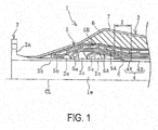
FIG. 1 is a vertical cross-sectional view illustrating the upper half of an end portion in the longitudinal direction of the marine hose according to an embodiment of the present invention. -
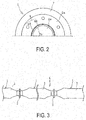
FIG. 2 is an explanatory diagram illustrating the marine hose ofFIG. 1 from a front view (arrow view of the region from one connection fitting side to the other connection fitting side). -
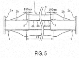
FIG. 3 is an explanatory diagram illustrating a hose line formed by connecting the marine hoses. -
FIG. 4 is a vertical cross-sectional view illustrating a state in which the marine hose ofFIG. 1 undergoes bending deformation. -
FIG. 5 is an explanatory diagram illustrating another embodiment of the marine hose from a side view. - The marine hose of the present invention will be described hereinafter based on an embodiment illustrated in the drawings.
- A
marine hose 1 according to an embodiment of the present invention illustrated inFIGS. 1 and2 includes ahose body 3 and a connection fitting 2 connected to both end parts of thehose body 3 in the longitudinal direction. As illustrated inFIG. 3 , a plurality ofmarine hoses 1 are connected viarespective connection fittings 2 to form a hose line L. In this embodiment, the hose line L is in a state of floating in the ocean, and external forces act on themarine hose 1 due to waves, wind, tidal currents, and the like. Themarine hose 1 therefore undergoes various deformations such as elongation, bending, and twisting. - The
hose body 3 includes an inner surface layer 4, a reinforcinglayer 5 disposed on the outer circumferential side of the inner surface 4 (main reinforcing layer 5A and mainbody wire layer 5B), and anouter surface layer 7 disposed on the outer circumferential side of the reinforcinglayer 5. Other necessary members are also provided as necessary on thehose body 3. Since themarine hose 1 of this embodiment is a floating-type hose, abuoyant layer 6 formed from a buoyant material such as a sponge is interposed between the reinforcinglayer 5 and theouter surface layer 7. The present invention can be applied not only to a floating-typemarine hose 1, but also to a submarine-type marine hose which does not have abuoyant layer 6. - The
connection fitting 2 includes a disc-shaped flange 2a and atubular nipple 2b, wherein a tip side coupled with theflange 2a is inserted into thehose body 3. The outer circumferential surface of the tip of thenipple 2b is an inclined surface in which the outer diameter of the nipple decreases toward the tip side. The inner surface layer 4, the main reinforcinglayer 5A, and the mainbody wire layer 5B are sequentially wrapped and layered toward the outer circumferential side on the outer circumference of thenipple 2b, and the outermost periphery is covered by theouter surface layer 7. The inner circumferential side of the inner surface layer 4 serves as a fluid flow path 1a. The line CL illustrated inFIG. 1 is a center line extending in the axial direction of themarine hose 1. - A fluid transported through the
marine hose 1 is in direct contact with the inner circumferential surface of the inner surface layer 4. The inner surface layer 4 is made of an acrylonitrile rubber or the like having excellent oil resistance, for example. The details of the inner surface layer 4 will be given below. - The main
body wire layer 5B is formed by winding a metal wire in a spiral-like manner at predetermined intervals around the outer circumferential rubber layer of the main reinforcinglayer 5A. The main reinforcinglayer 5A is formed by layering a plurality of reinforcing cord layers prepared by coating reinforcing cords with rubber. - The
nipple wires layer 5A and the mainbody wire layer 5B are fixed to thenipple 2b by afixing ring 2c or the like protruding from the outer circumferential surface of thenipple 2b. Theouter surface layer 7 is made of a non-water-permeable material such as a rubber. - A portion or all of the range in the longitudinal direction of the
hose body 3 of the inner surface layer 4 has a layered structure in which a plurality of rubber layers having different physical properties are layered in the radial direction of thehose body 3. Specifically, a range Z of at least around 100 mm in the longitudinal direction of thehose body 3, with respect to an insertion side end E of the connection fitting 2 of the inner surface layer 4, assumes this layered structure. In this embodiment, the inner surface layer 4 has a two-layer structure including afirst rubber layer 4A and asecond rubber layer 4B on the outer circumferential side of the first rubber layer. The number of layers can be determined appropriately and may be, for example, around 2 to 4 layers. In addition, in this embodiment, the layered structure is disposed in the range Z of around 100 mm in the longitudinal direction of thehose body 3 with respect to the insertion side end E of theconnection fitting 2. - The rubber of the
first rubber layer 4A has an elongation at break of not less than 700% and not greater than 750%. The elongation at break in the present invention is a measurement determined by the test method specified in ISO 37. A larger value of elongation at break indicates superior flexibility. Further, the rubber of thefirst rubber layer 4A exhibits an expansion coefficient of greater than 30% and not greater than 40% after 48 hours of immersion at 40°C in each of IRM 901, IRM 902, and IRM 903 specified in ISO 1817 in a test method according tomethod 2 of ISO 6722. A smaller value of the expansion coefficient indicates superior oil resistance. - The rubber of the
second rubber layer 4B has an elongation at break of not less than 550% and not greater than 600%. Further, the rubber of thesecond rubber layer 4B exhibits an expansion coefficient of not greater than 30%. For example, the value of the expansion coefficient is not less than 20% and not greater than 30%. - Accordingly, the rubber of the
first rubber layer 4A has a certain level of oil resistance and exhibits flexibility superior to that of the rubber of thesecond rubber layer 4B. The rubber of thesecond rubber layer 4B has a certain level of flexibility and exhibits oil resistance superior to that of the rubber of thefirst rubber layer 4A. - When an external force acts on the marine hose 1 (hose body 3) and the
hose body 3 undergoes bending deformation as illustrated inFIG. 4 , stress is concentrated on the inner surface layer 4 in the vicinity of the tip E of thenipple 2b. In themarine hose 1 according to an embodiment of the present invention, the range Z in which stress is most concentrated when an external force acts on thehose body 3, that is, the range Z of around 100 mm in the longitudinal direction of thehose body 3 with respect to the insertion side end E of the connection fitting 2 has the layered structure described above. - The rubber of the
first rubber layer 4A has a certain level of oil resistance and exhibits excellent flexibility and a relatively large elongation at break, which is advantageous for mitigating stress concentration. Therefore, cracks are unlikely to form even when thehose body 3 undergoes bending deformation. Moreover, since the rubber has a certain level of oil resistance, a sufficient service life can be secured, even when the fluid to be transported is crude oil or the like. In addition, even when cracks are formed in thefirst rubber layer 4A, thesecond rubber layer 4B adjacent to the outer circumferential side has oil resistance superior to that of thefirst rubber layer 4A. Therefore, a sufficient service life can be secured. Since thesecond rubber layer 4B has a certain level of flexibility and is not be in direct contact with the connection fitting 2 (nipple 2b), the layer is unlikely to undergo stress greater than that of thefirst rubber layer 4A. Therefore, even when thehose body 3 undergoes bending deformation, cracks are not easily formed in thesecond rubber layer 4B. - In this way, the functions of the
marine hose 1 according to an embodiment of the present invention are divided between thefirst rubber layer 4A primarily responsible for flexibility and thesecond rubber layer 4B primarily responsible for oil resistance by using a special layered structure for the inner surface layer 4. It may appear to be better to increase the oil resistance of the innermostfirst rubber layer 4A, which is in direct contact with the fluid, rather than thesecond rubber layer 4B. However, it is presently difficult to obtain a rubber which exhibits high oil resistance and high flexibility. In addition, no matter how high the oil resistance may be, the oil resistance will not function when the layer is damaged due to cracking. Therefore, it is actually more important for the innermostfirst rubber layer 4A to exhibit a performance (flexibility) in which cracks are less likely to form than to exhibit oil resistance. Accordingly, such special layered structure can balance high flexibility and high oil resistance for the entire inner surface layer 4. - The thickness of the inner surface layer 4 may be, for example, not less than 3 mm; the thickness of the innermost
first rubber layer 4A may be not less than 1 mm; and the total thickness of the rubber layers constituting the inner surface layer 4 other than thefirst rubber layer 4A (in this embodiment, only thesecond rubber layer 4B) may be not less than 2 mm. With this specification, the high oil resistance of the inner surface layer 4 is easy to maintain stably. Taking into consideration the ease of production and the like, the inner surface layer 4 preferably has a two-layer structure. Note that the upper limits of the thicknesses of the inner surface layer 4 and thefirst rubber layer 4A and the upper limit of the total thickness of the rubber layers constituting the inner surface layer 4 other than thefirst rubber layer 4A are determined appropriately within a range that does not excessively diminish the flexibility of the inner surface layer 4 and are determined, for example, within a range of 14 mm. - As in this embodiment, in the specification in which the layered structure of the inner surface layer 4 is disposed only in the range Z of around 100 mm in the longitudinal direction of the
hose body 3 with respect to the insertion side end E of the connection fitting 2, high flexibility and high oil resistance of the inner surface layer 4 can be balanced effectively while the range of this special layered structure can be minimized. - As illustrated in
FIG. 5 , the special layered structure of the inner surface layer 4 may also be provided in a range Z1 extending from a position of 100 mm on the back side in the longitudinal direction of thehose body 3 with respect to the insertion side end E of the connection fitting 2 (nipple 2b) on one end side to a position of 100 mm on the back side in the longitudinal direction of thehose body 3 with respect to the insertion side end E of the connection fitting 2 (nipple 2b) on the other end side. Alternatively, the special layered structure of the inner surface layer 4 may also be provided over the entire longitudinal direction (entire range) of thehose body 3. -
- 1 Marine hose
- 1a Fluid flow path
- 2 Connection fitting
- 2a Flange
- 2b Nipple
- 2c Fixing ring
- 3 Hose body
- 4 Inner surface layer
- 4A First rubber layer
- 4B Second rubber layer
- 5 Reinforcing layer
- 5A Main reinforcing layer
- 5a Nipple wire
- 5B Main body wire layer
- 5b Nipple wire
- 6 Buoyant layer
- 7 Outer surface layer
- L Hose line
Claims (4)
- A marine hose comprising:a hose body including an inner surface layer, a reinforcing layer disposed on an outer circumferential side of the inner surface layer, and an outer surface layer disposed on an outer circumferential side of the reinforcing layer; anda connection fitting connected to both end parts of the hose body in a longitudinal direction;a range of at least around 100 mm in the longitudinal direction of the hose body, with respect to an insertion side end of the connection fitting of the inner surface layer, being a layered structure in which a plurality of rubber layers having different physical properties are layered in a radial direction of the hose body;a rubber in the innermost rubber layer of the layered structure having an elongation at break of not less than 700% and not greater than 750%, and having an expansion coefficient of greater than 30% and not greater than 40% after 48 hours of immersion at 40°C in each of IRM 901, IRM 902, and IRM 903 specified in ISO 1817 in a test method according to method 2 of ISO 6722; anda rubber in the rubber layers constituting the inner surface layer other than the innermost rubber layer having an elongation at break of not less than 550% and not greater than 600%, and having an expansion coefficient of not greater than 30% after 48 hours of immersion at 40°C in each of IRM 901, IRM 902, and IRM 903 specified in ISO 1817 in the test method according to method 2 of ISO 6722.
- The marine hose according to claim 1, wherein
a thickness of the inner surface layer is not less than 3 mm;
a thickness of the innermost rubber layer is not less than 1 mm; and
a total thickness of rubber layers constituting the inner surface layer other than the innermost rubber layer is not less than 2 mm. - The marine hose according to claim 1 or 2, wherein the inner surface layer has a two-layer structure.
- The marine hose according to any one of claims 1 to 3, wherein the layered structure is only disposed over a range of around 100 mm in the longitudinal direction of the hose body with respect to the insertion side end of the connection fitting.
Applications Claiming Priority (2)
| Application Number | Priority Date | Filing Date | Title |
|---|---|---|---|
| JP2016019914A JP6623800B2 (en) | 2016-02-04 | 2016-02-04 | Marine hose |
| PCT/JP2017/001661 WO2017135040A1 (en) | 2016-02-04 | 2017-01-19 | Marine hose |
Publications (2)
| Publication Number | Publication Date |
|---|---|
| EP3412950A1 true EP3412950A1 (en) | 2018-12-12 |
| EP3412950A4 EP3412950A4 (en) | 2019-09-11 |
Family
ID=59499581
Family Applications (1)
| Application Number | Title | Priority Date | Filing Date |
|---|---|---|---|
| EP17747199.2A Withdrawn EP3412950A4 (en) | 2016-02-04 | 2017-01-19 | Marine hose |
Country Status (5)
| Country | Link |
|---|---|
| EP (1) | EP3412950A4 (en) |
| JP (1) | JP6623800B2 (en) |
| CN (1) | CN108603620B (en) |
| BR (1) | BR112018015852A2 (en) |
| WO (1) | WO2017135040A1 (en) |
Families Citing this family (2)
| Publication number | Priority date | Publication date | Assignee | Title |
|---|---|---|---|---|
| JP7225949B2 (en) * | 2019-03-12 | 2023-02-21 | 横浜ゴム株式会社 | Marine hose fluid leak detector |
| JP7846334B2 (en) * | 2022-02-09 | 2026-04-15 | 横浜ゴム株式会社 | Method for determining the specifications of fiber reinforcement material for marine hoses and method for manufacturing marine hoses |
Family Cites Families (13)
| Publication number | Priority date | Publication date | Assignee | Title |
|---|---|---|---|---|
| US4148342A (en) * | 1976-05-27 | 1979-04-10 | The Goodyear Tire & Rubber Company | Hose structure and method for making |
| GB2031542A (en) * | 1978-10-09 | 1980-04-23 | Shell Int Research | Improvements in and relating to hoses |
| GB9224549D0 (en) * | 1992-11-24 | 1993-01-13 | Dunlop Ltd | Hose end fitting and hose assembly |
| JP2815306B2 (en) * | 1993-08-31 | 1998-10-27 | 株式会社ニチリン | Composite flexible hose |
| EP1148283A3 (en) * | 2000-04-21 | 2003-04-02 | Bridgestone Corporation | Refrigerant transporting rubber hose |
| JP2006144878A (en) | 2004-11-18 | 2006-06-08 | Yokohama Rubber Co Ltd:The | Marine hose |
| JP4877158B2 (en) * | 2007-08-29 | 2012-02-15 | 横浜ゴム株式会社 | Fluid transfer hose |
| EP2707635A4 (en) * | 2011-05-13 | 2014-11-12 | Deepflex Inc | Reinforcement laminate having an alignment feature |
| JP5788751B2 (en) * | 2011-09-26 | 2015-10-07 | 電気化学工業株式会社 | Laminated body, cross-linked product and molded member |
| CN102537539B (en) * | 2012-01-16 | 2013-03-13 | 河北宇通特种胶管有限公司 | Floating hose for ocean oil transportation |
| JP5900316B2 (en) * | 2012-12-21 | 2016-04-06 | 横浜ゴム株式会社 | Marine hose manufacturing method |
| JP2015068499A (en) * | 2013-10-01 | 2015-04-13 | 横浜ゴム株式会社 | Fluid transporting hose |
| CN203927124U (en) * | 2014-04-08 | 2014-11-05 | 王娜娜 | A kind of flexible hose of carrying electric current or fluent material |
-
2016
- 2016-02-04 JP JP2016019914A patent/JP6623800B2/en not_active Expired - Fee Related
-
2017
- 2017-01-19 WO PCT/JP2017/001661 patent/WO2017135040A1/en not_active Ceased
- 2017-01-19 EP EP17747199.2A patent/EP3412950A4/en not_active Withdrawn
- 2017-01-19 BR BR112018015852-6A patent/BR112018015852A2/en not_active Application Discontinuation
- 2017-01-19 CN CN201780008114.2A patent/CN108603620B/en not_active Expired - Fee Related
Also Published As
| Publication number | Publication date |
|---|---|
| BR112018015852A2 (en) | 2018-12-26 |
| JP2017137958A (en) | 2017-08-10 |
| CN108603620B (en) | 2019-04-23 |
| EP3412950A4 (en) | 2019-09-11 |
| JP6623800B2 (en) | 2019-12-25 |
| WO2017135040A1 (en) | 2017-08-10 |
| CN108603620A (en) | 2018-09-28 |
Similar Documents
| Publication | Publication Date | Title |
|---|---|---|
| US6538198B1 (en) | Marine umbilical | |
| US8955553B2 (en) | Flexible pipe body with buoyancy element and method of producing same | |
| AU2007259104B2 (en) | Radius control | |
| CN110462273A (en) | Hose End Construction and Fittings | |
| CN105163878B (en) | Flexible pipe and method of manufacturing flexible pipe | |
| EP3412951B1 (en) | Marine hose status monitoring system | |
| BR112014030179B1 (en) | riser tube to carry fluid between a superior installation and an underwater installation | |
| EP3412952B1 (en) | Marine hose status monitoring system | |
| US20150020910A1 (en) | Bend limiter | |
| WO2016170360A1 (en) | Flexible pipe components and method of manufacture of flexible pipe | |
| CN110546305A (en) | Provision of electrical continuity and/or radial support | |
| CN111919054B (en) | Flexible pipe body and method | |
| JP2009532637A (en) | Flexible pipe with integral end fitting | |
| JP6623800B2 (en) | Marine hose | |
| US10393306B2 (en) | Fatigue life extender | |
| WO2019239093A1 (en) | Venting apparatus and method | |
| US8910668B2 (en) | Hose for transporting fluids | |
| JP7853543B2 (en) | Fluid transport hose | |
| CN112513331A (en) | Tube body cathodic protection | |
| CN206546732U (en) | A kind of seafari fiber optic cables | |
| JP5056609B2 (en) | Fluid transfer hose |
Legal Events
| Date | Code | Title | Description |
|---|---|---|---|
| STAA | Information on the status of an ep patent application or granted ep patent |
Free format text: STATUS: THE INTERNATIONAL PUBLICATION HAS BEEN MADE |
|
| PUAI | Public reference made under article 153(3) epc to a published international application that has entered the european phase |
Free format text: ORIGINAL CODE: 0009012 |
|
| STAA | Information on the status of an ep patent application or granted ep patent |
Free format text: STATUS: REQUEST FOR EXAMINATION WAS MADE |
|
| 17P | Request for examination filed |
Effective date: 20180829 |
|
| AK | Designated contracting states |
Kind code of ref document: A1 Designated state(s): AL AT BE BG CH CY CZ DE DK EE ES FI FR GB GR HR HU IE IS IT LI LT LU LV MC MK MT NL NO PL PT RO RS SE SI SK SM TR |
|
| AX | Request for extension of the european patent |
Extension state: BA ME |
|
| DAV | Request for validation of the european patent (deleted) | ||
| DAX | Request for extension of the european patent (deleted) | ||
| A4 | Supplementary search report drawn up and despatched |
Effective date: 20190812 |
|
| RIC1 | Information provided on ipc code assigned before grant |
Ipc: F16L 33/28 20060101AFI20190806BHEP Ipc: F16L 11/133 20060101ALN20190806BHEP Ipc: F16L 11/08 20060101ALI20190806BHEP Ipc: F16L 33/01 20060101ALI20190806BHEP |
|
| GRAP | Despatch of communication of intention to grant a patent |
Free format text: ORIGINAL CODE: EPIDOSNIGR1 |
|
| STAA | Information on the status of an ep patent application or granted ep patent |
Free format text: STATUS: GRANT OF PATENT IS INTENDED |
|
| RIC1 | Information provided on ipc code assigned before grant |
Ipc: F16L 11/08 20060101ALI20200506BHEP Ipc: F16L 33/28 20060101AFI20200506BHEP Ipc: F16L 33/01 20060101ALI20200506BHEP Ipc: F16L 11/133 20060101ALN20200506BHEP |
|
| INTG | Intention to grant announced |
Effective date: 20200608 |
|
| RIN1 | Information on inventor provided before grant (corrected) |
Inventor name: FUSE, NORIYUKI Inventor name: ONO, SHUNICHI |
|
| STAA | Information on the status of an ep patent application or granted ep patent |
Free format text: STATUS: THE APPLICATION IS DEEMED TO BE WITHDRAWN |
|
| 18D | Application deemed to be withdrawn |
Effective date: 20201020 |