EP3412912A1 - Fluid delivery system - Google Patents
Fluid delivery system Download PDFInfo
- Publication number
- EP3412912A1 EP3412912A1 EP18175431.8A EP18175431A EP3412912A1 EP 3412912 A1 EP3412912 A1 EP 3412912A1 EP 18175431 A EP18175431 A EP 18175431A EP 3412912 A1 EP3412912 A1 EP 3412912A1
- Authority
- EP
- European Patent Office
- Prior art keywords
- fluid
- valve
- pump
- flow
- auxiliary system
- Prior art date
- Legal status (The legal status is an assumption and is not a legal conclusion. Google has not performed a legal analysis and makes no representation as to the accuracy of the status listed.)
- Granted
Links
Images


Classifications
-
- B—PERFORMING OPERATIONS; TRANSPORTING
- B60—VEHICLES IN GENERAL
- B60T—VEHICLE BRAKE CONTROL SYSTEMS OR PARTS THEREOF; BRAKE CONTROL SYSTEMS OR PARTS THEREOF, IN GENERAL; ARRANGEMENT OF BRAKING ELEMENTS ON VEHICLES IN GENERAL; PORTABLE DEVICES FOR PREVENTING UNWANTED MOVEMENT OF VEHICLES; VEHICLE MODIFICATIONS TO FACILITATE COOLING OF BRAKES
- B60T13/00—Transmitting braking action from initiating means to ultimate brake actuator with power assistance or drive; Brake systems incorporating such transmitting means, e.g. air-pressure brake systems
- B60T13/10—Transmitting braking action from initiating means to ultimate brake actuator with power assistance or drive; Brake systems incorporating such transmitting means, e.g. air-pressure brake systems with fluid assistance, drive, or release
- B60T13/12—Transmitting braking action from initiating means to ultimate brake actuator with power assistance or drive; Brake systems incorporating such transmitting means, e.g. air-pressure brake systems with fluid assistance, drive, or release the fluid being liquid
- B60T13/14—Transmitting braking action from initiating means to ultimate brake actuator with power assistance or drive; Brake systems incorporating such transmitting means, e.g. air-pressure brake systems with fluid assistance, drive, or release the fluid being liquid using accumulators or reservoirs fed by pumps
-
- B—PERFORMING OPERATIONS; TRANSPORTING
- B60—VEHICLES IN GENERAL
- B60T—VEHICLE BRAKE CONTROL SYSTEMS OR PARTS THEREOF; BRAKE CONTROL SYSTEMS OR PARTS THEREOF, IN GENERAL; ARRANGEMENT OF BRAKING ELEMENTS ON VEHICLES IN GENERAL; PORTABLE DEVICES FOR PREVENTING UNWANTED MOVEMENT OF VEHICLES; VEHICLE MODIFICATIONS TO FACILITATE COOLING OF BRAKES
- B60T17/00—Component parts, details, or accessories of power brake systems not covered by groups B60T8/00, B60T13/00 or B60T15/00, or presenting other characteristic features
- B60T17/02—Arrangements of pumps or compressors, or control devices therefor
-
- B—PERFORMING OPERATIONS; TRANSPORTING
- B60—VEHICLES IN GENERAL
- B60T—VEHICLE BRAKE CONTROL SYSTEMS OR PARTS THEREOF; BRAKE CONTROL SYSTEMS OR PARTS THEREOF, IN GENERAL; ARRANGEMENT OF BRAKING ELEMENTS ON VEHICLES IN GENERAL; PORTABLE DEVICES FOR PREVENTING UNWANTED MOVEMENT OF VEHICLES; VEHICLE MODIFICATIONS TO FACILITATE COOLING OF BRAKES
- B60T13/00—Transmitting braking action from initiating means to ultimate brake actuator with power assistance or drive; Brake systems incorporating such transmitting means, e.g. air-pressure brake systems
- B60T13/10—Transmitting braking action from initiating means to ultimate brake actuator with power assistance or drive; Brake systems incorporating such transmitting means, e.g. air-pressure brake systems with fluid assistance, drive, or release
- B60T13/12—Transmitting braking action from initiating means to ultimate brake actuator with power assistance or drive; Brake systems incorporating such transmitting means, e.g. air-pressure brake systems with fluid assistance, drive, or release the fluid being liquid
- B60T13/14—Transmitting braking action from initiating means to ultimate brake actuator with power assistance or drive; Brake systems incorporating such transmitting means, e.g. air-pressure brake systems with fluid assistance, drive, or release the fluid being liquid using accumulators or reservoirs fed by pumps
- B60T13/148—Arrangements for pressure supply
-
- B—PERFORMING OPERATIONS; TRANSPORTING
- B60—VEHICLES IN GENERAL
- B60T—VEHICLE BRAKE CONTROL SYSTEMS OR PARTS THEREOF; BRAKE CONTROL SYSTEMS OR PARTS THEREOF, IN GENERAL; ARRANGEMENT OF BRAKING ELEMENTS ON VEHICLES IN GENERAL; PORTABLE DEVICES FOR PREVENTING UNWANTED MOVEMENT OF VEHICLES; VEHICLE MODIFICATIONS TO FACILITATE COOLING OF BRAKES
- B60T13/00—Transmitting braking action from initiating means to ultimate brake actuator with power assistance or drive; Brake systems incorporating such transmitting means, e.g. air-pressure brake systems
- B60T13/10—Transmitting braking action from initiating means to ultimate brake actuator with power assistance or drive; Brake systems incorporating such transmitting means, e.g. air-pressure brake systems with fluid assistance, drive, or release
- B60T13/12—Transmitting braking action from initiating means to ultimate brake actuator with power assistance or drive; Brake systems incorporating such transmitting means, e.g. air-pressure brake systems with fluid assistance, drive, or release the fluid being liquid
- B60T13/16—Transmitting braking action from initiating means to ultimate brake actuator with power assistance or drive; Brake systems incorporating such transmitting means, e.g. air-pressure brake systems with fluid assistance, drive, or release the fluid being liquid using pumps directly, i.e. without interposition of accumulators or reservoirs
-
- B—PERFORMING OPERATIONS; TRANSPORTING
- B60—VEHICLES IN GENERAL
- B60T—VEHICLE BRAKE CONTROL SYSTEMS OR PARTS THEREOF; BRAKE CONTROL SYSTEMS OR PARTS THEREOF, IN GENERAL; ARRANGEMENT OF BRAKING ELEMENTS ON VEHICLES IN GENERAL; PORTABLE DEVICES FOR PREVENTING UNWANTED MOVEMENT OF VEHICLES; VEHICLE MODIFICATIONS TO FACILITATE COOLING OF BRAKES
- B60T13/00—Transmitting braking action from initiating means to ultimate brake actuator with power assistance or drive; Brake systems incorporating such transmitting means, e.g. air-pressure brake systems
- B60T13/10—Transmitting braking action from initiating means to ultimate brake actuator with power assistance or drive; Brake systems incorporating such transmitting means, e.g. air-pressure brake systems with fluid assistance, drive, or release
- B60T13/66—Electrical control in fluid-pressure brake systems
- B60T13/662—Electrical control in fluid-pressure brake systems characterised by specified functions of the control system components
-
- B—PERFORMING OPERATIONS; TRANSPORTING
- B60—VEHICLES IN GENERAL
- B60T—VEHICLE BRAKE CONTROL SYSTEMS OR PARTS THEREOF; BRAKE CONTROL SYSTEMS OR PARTS THEREOF, IN GENERAL; ARRANGEMENT OF BRAKING ELEMENTS ON VEHICLES IN GENERAL; PORTABLE DEVICES FOR PREVENTING UNWANTED MOVEMENT OF VEHICLES; VEHICLE MODIFICATIONS TO FACILITATE COOLING OF BRAKES
- B60T13/00—Transmitting braking action from initiating means to ultimate brake actuator with power assistance or drive; Brake systems incorporating such transmitting means, e.g. air-pressure brake systems
- B60T13/10—Transmitting braking action from initiating means to ultimate brake actuator with power assistance or drive; Brake systems incorporating such transmitting means, e.g. air-pressure brake systems with fluid assistance, drive, or release
- B60T13/66—Electrical control in fluid-pressure brake systems
- B60T13/68—Electrical control in fluid-pressure brake systems by electrically-controlled valves
-
- B—PERFORMING OPERATIONS; TRANSPORTING
- B60—VEHICLES IN GENERAL
- B60T—VEHICLE BRAKE CONTROL SYSTEMS OR PARTS THEREOF; BRAKE CONTROL SYSTEMS OR PARTS THEREOF, IN GENERAL; ARRANGEMENT OF BRAKING ELEMENTS ON VEHICLES IN GENERAL; PORTABLE DEVICES FOR PREVENTING UNWANTED MOVEMENT OF VEHICLES; VEHICLE MODIFICATIONS TO FACILITATE COOLING OF BRAKES
- B60T13/00—Transmitting braking action from initiating means to ultimate brake actuator with power assistance or drive; Brake systems incorporating such transmitting means, e.g. air-pressure brake systems
- B60T13/10—Transmitting braking action from initiating means to ultimate brake actuator with power assistance or drive; Brake systems incorporating such transmitting means, e.g. air-pressure brake systems with fluid assistance, drive, or release
- B60T13/66—Electrical control in fluid-pressure brake systems
- B60T13/68—Electrical control in fluid-pressure brake systems by electrically-controlled valves
- B60T13/686—Electrical control in fluid-pressure brake systems by electrically-controlled valves in hydraulic systems or parts thereof
-
- B—PERFORMING OPERATIONS; TRANSPORTING
- B60—VEHICLES IN GENERAL
- B60T—VEHICLE BRAKE CONTROL SYSTEMS OR PARTS THEREOF; BRAKE CONTROL SYSTEMS OR PARTS THEREOF, IN GENERAL; ARRANGEMENT OF BRAKING ELEMENTS ON VEHICLES IN GENERAL; PORTABLE DEVICES FOR PREVENTING UNWANTED MOVEMENT OF VEHICLES; VEHICLE MODIFICATIONS TO FACILITATE COOLING OF BRAKES
- B60T15/00—Construction arrangement, or operation of valves incorporated in power brake systems and not covered by groups B60T11/00 or B60T13/00
- B60T15/02—Application and release valves
- B60T15/36—Other control devices or valves characterised by definite functions
- B60T15/48—Other control devices or valves characterised by definite functions for filling reservoirs
- B60T15/50—Other control devices or valves characterised by definite functions for filling reservoirs with means for limiting or relieving pressure in reservoirs
-
- B—PERFORMING OPERATIONS; TRANSPORTING
- B60—VEHICLES IN GENERAL
- B60T—VEHICLE BRAKE CONTROL SYSTEMS OR PARTS THEREOF; BRAKE CONTROL SYSTEMS OR PARTS THEREOF, IN GENERAL; ARRANGEMENT OF BRAKING ELEMENTS ON VEHICLES IN GENERAL; PORTABLE DEVICES FOR PREVENTING UNWANTED MOVEMENT OF VEHICLES; VEHICLE MODIFICATIONS TO FACILITATE COOLING OF BRAKES
- B60T17/00—Component parts, details, or accessories of power brake systems not covered by groups B60T8/00, B60T13/00 or B60T15/00, or presenting other characteristic features
- B60T17/04—Arrangements of piping, valves in the piping, e.g. cut-off valves, couplings or air hoses
-
- B—PERFORMING OPERATIONS; TRANSPORTING
- B60—VEHICLES IN GENERAL
- B60T—VEHICLE BRAKE CONTROL SYSTEMS OR PARTS THEREOF; BRAKE CONTROL SYSTEMS OR PARTS THEREOF, IN GENERAL; ARRANGEMENT OF BRAKING ELEMENTS ON VEHICLES IN GENERAL; PORTABLE DEVICES FOR PREVENTING UNWANTED MOVEMENT OF VEHICLES; VEHICLE MODIFICATIONS TO FACILITATE COOLING OF BRAKES
- B60T17/00—Component parts, details, or accessories of power brake systems not covered by groups B60T8/00, B60T13/00 or B60T15/00, or presenting other characteristic features
- B60T17/18—Safety devices; Monitoring
- B60T17/22—Devices for monitoring or checking brake systems; Signal devices
- B60T17/221—Procedure or apparatus for checking or keeping in a correct functioning condition of brake systems
- B60T17/222—Procedure or apparatus for checking or keeping in a correct functioning condition of brake systems by filling or bleeding of hydraulic systems
-
- B—PERFORMING OPERATIONS; TRANSPORTING
- B60—VEHICLES IN GENERAL
- B60T—VEHICLE BRAKE CONTROL SYSTEMS OR PARTS THEREOF; BRAKE CONTROL SYSTEMS OR PARTS THEREOF, IN GENERAL; ARRANGEMENT OF BRAKING ELEMENTS ON VEHICLES IN GENERAL; PORTABLE DEVICES FOR PREVENTING UNWANTED MOVEMENT OF VEHICLES; VEHICLE MODIFICATIONS TO FACILITATE COOLING OF BRAKES
- B60T8/00—Arrangements for adjusting wheel-braking force to meet varying vehicular or ground-surface conditions, e.g. limiting or varying distribution of braking force
- B60T8/17—Using electrical or electronic regulation means to control braking
- B60T8/173—Eliminating or reducing the effect of unwanted signals, e.g. due to vibrations or electrical noise
-
- B—PERFORMING OPERATIONS; TRANSPORTING
- B60—VEHICLES IN GENERAL
- B60T—VEHICLE BRAKE CONTROL SYSTEMS OR PARTS THEREOF; BRAKE CONTROL SYSTEMS OR PARTS THEREOF, IN GENERAL; ARRANGEMENT OF BRAKING ELEMENTS ON VEHICLES IN GENERAL; PORTABLE DEVICES FOR PREVENTING UNWANTED MOVEMENT OF VEHICLES; VEHICLE MODIFICATIONS TO FACILITATE COOLING OF BRAKES
- B60T8/00—Arrangements for adjusting wheel-braking force to meet varying vehicular or ground-surface conditions, e.g. limiting or varying distribution of braking force
- B60T8/32—Arrangements for adjusting wheel-braking force to meet varying vehicular or ground-surface conditions, e.g. limiting or varying distribution of braking force responsive to a speed condition, e.g. acceleration or deceleration
- B60T8/34—Arrangements for adjusting wheel-braking force to meet varying vehicular or ground-surface conditions, e.g. limiting or varying distribution of braking force responsive to a speed condition, e.g. acceleration or deceleration having a fluid pressure regulator responsive to a speed condition
- B60T8/48—Arrangements for adjusting wheel-braking force to meet varying vehicular or ground-surface conditions, e.g. limiting or varying distribution of braking force responsive to a speed condition, e.g. acceleration or deceleration having a fluid pressure regulator responsive to a speed condition connecting the brake actuator to an alternative or additional source of fluid pressure, e.g. traction control systems
-
- F—MECHANICAL ENGINEERING; LIGHTING; HEATING; WEAPONS; BLASTING
- F04—POSITIVE - DISPLACEMENT MACHINES FOR LIQUIDS; PUMPS FOR LIQUIDS OR ELASTIC FLUIDS
- F04B—POSITIVE-DISPLACEMENT MACHINES FOR LIQUIDS; PUMPS
- F04B23/00—Pumping installations or systems
- F04B23/02—Pumping installations or systems having reservoirs
-
- F—MECHANICAL ENGINEERING; LIGHTING; HEATING; WEAPONS; BLASTING
- F04—POSITIVE - DISPLACEMENT MACHINES FOR LIQUIDS; PUMPS FOR LIQUIDS OR ELASTIC FLUIDS
- F04B—POSITIVE-DISPLACEMENT MACHINES FOR LIQUIDS; PUMPS
- F04B49/00—Control, e.g. of pump delivery, or pump pressure of, or safety measures for, machines, pumps, or pumping installations, not otherwise provided for, or of interest apart from, groups F04B1/00 - F04B47/00
- F04B49/02—Stopping, starting, unloading or idling control
- F04B49/022—Stopping, starting, unloading or idling control by means of pressure
-
- F—MECHANICAL ENGINEERING; LIGHTING; HEATING; WEAPONS; BLASTING
- F04—POSITIVE - DISPLACEMENT MACHINES FOR LIQUIDS; PUMPS FOR LIQUIDS OR ELASTIC FLUIDS
- F04B—POSITIVE-DISPLACEMENT MACHINES FOR LIQUIDS; PUMPS
- F04B49/00—Control, e.g. of pump delivery, or pump pressure of, or safety measures for, machines, pumps, or pumping installations, not otherwise provided for, or of interest apart from, groups F04B1/00 - F04B47/00
- F04B49/02—Stopping, starting, unloading or idling control
- F04B49/03—Stopping, starting, unloading or idling control by means of valves
-
- F—MECHANICAL ENGINEERING; LIGHTING; HEATING; WEAPONS; BLASTING
- F04—POSITIVE - DISPLACEMENT MACHINES FOR LIQUIDS; PUMPS FOR LIQUIDS OR ELASTIC FLUIDS
- F04B—POSITIVE-DISPLACEMENT MACHINES FOR LIQUIDS; PUMPS
- F04B49/00—Control, e.g. of pump delivery, or pump pressure of, or safety measures for, machines, pumps, or pumping installations, not otherwise provided for, or of interest apart from, groups F04B1/00 - F04B47/00
- F04B49/02—Stopping, starting, unloading or idling control
- F04B49/03—Stopping, starting, unloading or idling control by means of valves
- F04B49/035—Bypassing
-
- F—MECHANICAL ENGINEERING; LIGHTING; HEATING; WEAPONS; BLASTING
- F04—POSITIVE - DISPLACEMENT MACHINES FOR LIQUIDS; PUMPS FOR LIQUIDS OR ELASTIC FLUIDS
- F04B—POSITIVE-DISPLACEMENT MACHINES FOR LIQUIDS; PUMPS
- F04B49/00—Control, e.g. of pump delivery, or pump pressure of, or safety measures for, machines, pumps, or pumping installations, not otherwise provided for, or of interest apart from, groups F04B1/00 - F04B47/00
- F04B49/06—Control using electricity
- F04B49/065—Control using electricity and making use of computers
-
- F—MECHANICAL ENGINEERING; LIGHTING; HEATING; WEAPONS; BLASTING
- F04—POSITIVE - DISPLACEMENT MACHINES FOR LIQUIDS; PUMPS FOR LIQUIDS OR ELASTIC FLUIDS
- F04B—POSITIVE-DISPLACEMENT MACHINES FOR LIQUIDS; PUMPS
- F04B7/00—Piston machines or pumps characterised by having positively-driven valving
- F04B7/0073—Piston machines or pumps characterised by having positively-driven valving the member being of the lost-motion type, e.g. friction-actuated members, or having means for pushing it against or pulling it from its seat
-
- F—MECHANICAL ENGINEERING; LIGHTING; HEATING; WEAPONS; BLASTING
- F15—FLUID-PRESSURE ACTUATORS; HYDRAULICS OR PNEUMATICS IN GENERAL
- F15B—SYSTEMS ACTING BY MEANS OF FLUIDS IN GENERAL; FLUID-PRESSURE ACTUATORS, e.g. SERVOMOTORS; DETAILS OF FLUID-PRESSURE SYSTEMS, NOT OTHERWISE PROVIDED FOR
- F15B1/00—Installations or systems with accumulators; Supply reservoir or sump assemblies
- F15B1/02—Installations or systems with accumulators
- F15B1/027—Installations or systems with accumulators having accumulator charging devices
-
- F—MECHANICAL ENGINEERING; LIGHTING; HEATING; WEAPONS; BLASTING
- F15—FLUID-PRESSURE ACTUATORS; HYDRAULICS OR PNEUMATICS IN GENERAL
- F15B—SYSTEMS ACTING BY MEANS OF FLUIDS IN GENERAL; FLUID-PRESSURE ACTUATORS, e.g. SERVOMOTORS; DETAILS OF FLUID-PRESSURE SYSTEMS, NOT OTHERWISE PROVIDED FOR
- F15B2201/00—Accumulators
- F15B2201/50—Monitoring, detection and testing means for accumulators
- F15B2201/51—Pressure detection
-
- F—MECHANICAL ENGINEERING; LIGHTING; HEATING; WEAPONS; BLASTING
- F15—FLUID-PRESSURE ACTUATORS; HYDRAULICS OR PNEUMATICS IN GENERAL
- F15B—SYSTEMS ACTING BY MEANS OF FLUIDS IN GENERAL; FLUID-PRESSURE ACTUATORS, e.g. SERVOMOTORS; DETAILS OF FLUID-PRESSURE SYSTEMS, NOT OTHERWISE PROVIDED FOR
- F15B2211/00—Circuits for servomotor systems
- F15B2211/20—Fluid pressure source, e.g. accumulator or variable axial piston pump
- F15B2211/205—Systems with pumps
- F15B2211/2053—Type of pump
- F15B2211/20546—Type of pump variable capacity
- F15B2211/20553—Type of pump variable capacity with pilot circuit, e.g. for controlling a swash plate
-
- F—MECHANICAL ENGINEERING; LIGHTING; HEATING; WEAPONS; BLASTING
- F15—FLUID-PRESSURE ACTUATORS; HYDRAULICS OR PNEUMATICS IN GENERAL
- F15B—SYSTEMS ACTING BY MEANS OF FLUIDS IN GENERAL; FLUID-PRESSURE ACTUATORS, e.g. SERVOMOTORS; DETAILS OF FLUID-PRESSURE SYSTEMS, NOT OTHERWISE PROVIDED FOR
- F15B2211/00—Circuits for servomotor systems
- F15B2211/60—Circuit components or control therefor
- F15B2211/61—Secondary circuits
-
- F—MECHANICAL ENGINEERING; LIGHTING; HEATING; WEAPONS; BLASTING
- F15—FLUID-PRESSURE ACTUATORS; HYDRAULICS OR PNEUMATICS IN GENERAL
- F15B—SYSTEMS ACTING BY MEANS OF FLUIDS IN GENERAL; FLUID-PRESSURE ACTUATORS, e.g. SERVOMOTORS; DETAILS OF FLUID-PRESSURE SYSTEMS, NOT OTHERWISE PROVIDED FOR
- F15B2211/00—Circuits for servomotor systems
- F15B2211/60—Circuit components or control therefor
- F15B2211/61—Secondary circuits
- F15B2211/611—Diverting circuits, e.g. for cooling or filtering
-
- F—MECHANICAL ENGINEERING; LIGHTING; HEATING; WEAPONS; BLASTING
- F15—FLUID-PRESSURE ACTUATORS; HYDRAULICS OR PNEUMATICS IN GENERAL
- F15B—SYSTEMS ACTING BY MEANS OF FLUIDS IN GENERAL; FLUID-PRESSURE ACTUATORS, e.g. SERVOMOTORS; DETAILS OF FLUID-PRESSURE SYSTEMS, NOT OTHERWISE PROVIDED FOR
- F15B2211/00—Circuits for servomotor systems
- F15B2211/60—Circuit components or control therefor
- F15B2211/625—Accumulators
-
- F—MECHANICAL ENGINEERING; LIGHTING; HEATING; WEAPONS; BLASTING
- F15—FLUID-PRESSURE ACTUATORS; HYDRAULICS OR PNEUMATICS IN GENERAL
- F15B—SYSTEMS ACTING BY MEANS OF FLUIDS IN GENERAL; FLUID-PRESSURE ACTUATORS, e.g. SERVOMOTORS; DETAILS OF FLUID-PRESSURE SYSTEMS, NOT OTHERWISE PROVIDED FOR
- F15B2211/00—Circuits for servomotor systems
- F15B2211/60—Circuit components or control therefor
- F15B2211/63—Electronic controllers
- F15B2211/6303—Electronic controllers using input signals
- F15B2211/6306—Electronic controllers using input signals representing a pressure
Definitions
- a machine such an articulated truck, having an auxiliary system, such as an automatic traction control, may employ a hydraulically operated cross axle differential.
- the differential may be powered by a hydraulic circuit associated with the machine.
- a braking circuit employed for providing hydraulic power to hydraulically operated brakes of the machine may be employed for providing hydraulic power to the differential as well.
- the hydraulic circuit may employ one or more hydraulic accumulators, inverse shuttle valves, or the like.
- the differential may be hydraulically coupled to the hydraulic circuit upstream of the inverse shuttle valve and the hydraulic accumulators.
- a working pressure of the hydraulic accumulators may be substantially greater than a working pressure of the differential.
- fluid under pressure may be delivered from the hydraulic accumulators to the differential through the inverse shuttle valve.
- the differential may induce a parasitic load on the hydraulic accumulators which may be primarily employed for powering the hydraulically operated brakes.
- the inverse shuttle valve may be generally designed for allowing fluid flow there through in one direction, such as towards the hydraulic accumulators.
- reverse flow of the fluid there through from the hydraulic accumulators towards the differential may result in vigorous movement of a valve element with respect to a valve seat of the inverse shuttle valve.
- This vibration may result in undesirable noise from the inverse shuttle valve, reduced valve life, and so on.
- U.S. Patent Number 5,700,070 describes a vehicle brake control device for reducing noise and pulsation while securing a pressure boost during an anti-skid control and traction control.
- the brake control device includes a main brake line routed through a master cylinder, an inlet valve, and a wheel cylinder.
- An accumulator to store hydraulic pressure is installed in the brake line between the master cylinder and the wheel cylinder.
- a system for delivering a fluid in a machine includes a pump configured to provide a flow of the fluid.
- the system includes a first valve in fluid communication with the pump and disposed downstream of the pump.
- the first valve is configured to move between a first position and a second position.
- the system includes a check valve in fluid communication with the pump and disposed downstream of the first valve.
- the system includes at least one accumulator in fluid communication with the pump and disposed downstream of the check valve.
- the system also includes an auxiliary system in fluid communication with the pump and disposed upstream of the check valve.
- the system further includes a control unit communicably coupled to the first valve and the auxiliary system.
- the control unit is configured to receive a signal indicative of a fluid demand from the auxiliary system.
- the control unit is also configured to selectively control the first valve in the first position to limit the flow of the fluid from the pump to the auxiliary system, and in the second position to allow the flow of the fluid from the pump to the auxiliary system based, at least in part, on the received signal.
- the check valve limits a flow of a fluid from the at least one accumulator to the auxiliary system.
- a method for providing a flow of a fluid in a machine includes a pump, a first valve, a second valve, a third valve, a check valve, an auxiliary system, at least one accumulator, and a pressure sensor.
- the method includes receiving a signal indicative of a fluid demand from the auxiliary system.
- the method also includes selectively controlling the first valve in a first position to limit a flow of the fluid from the pump to the auxiliary system, and in a second position to allow the flow of the fluid from the pump to the auxiliary system based, at least in part, on the received signal.
- the check valve limits a flow of a fluid from the at least one accumulator to the auxiliary system.
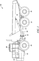
- FIG. 1 an exemplary machine 102 is illustrated. More specifically, the machine 102 is an articulated truck. The machine 102 is adapted to transport material, such as ore, soil, rocks, and so on, from one location to another. In other embodiments, the machine 102 may be any other machine, such as a mining truck, an off-highway truck, a haul truck, and so on. The machine 102 may be related to an industry including, but not limited to, construction, transportation, mining, material handling, forestry, agriculture, and waste management.
- the machine 102 includes a load bed 114 provided on the rear frame 110.
- the load bed 114 is adapted to load and unload material therefrom for transporting the material from one location to another.
- the machine 102 also includes one or more hydraulic cylinders 116 coupled between the rear frame 110 and the load bed 114.
- the hydraulic cylinders 116 are adapted to tilt the load bed 114 during unloading of the material.
- the machine 102 further includes a set of wheels 118 mounted to the front frame 104 and the rear frame 110. The wheels 118 are adapted to support and provide mobility to the machine 102 on the ground.
- the fluid delivery system 202 will be hereinafter interchangeably referred to as the system 202. More specifically, the system 202 is adapted to deliver a fluid to one or more hydraulically operated brakes (not shown) associated with the set of wheels 118 of the machine 102.
- the system 202 is also associated with an auxiliary system 204 associated with the machine 102.
- the auxiliary system 204 may be any hydraulically operated system of the machine 102, such as an automatic traction control system employing a hydraulically operated cross axle differential, an automatic transmission employing a hydraulically operated clutch, and so on.
- the system 202 includes a fluid sump 206.
- the fluid sump 206 is adapted to store the working fluid of the system 202 therein.
- the fluid is hydraulic oil. In other embodiments, the fluid may vary based on application requirements including, but not limited to, brake oil, transmission oil, and engine oil.
- the system 202 includes a pump 208 in fluid communication with the fluid sump 206.
- the pump 208 is operably coupled to a motor 210. Accordingly, in the illustrated embodiment, the pump 208 is driven by the motor 210. In other embodiments, the pump 208 may be operably coupled to and driven by the engine.
- the system 202 includes a first valve 214 in fluid communication with the pump 208. More specifically, the first valve 214 is disposed in the main line 212 and downstream of the pump 208. The first valve 214 is configured to move between a first position "P1" (shown in FIG. 2 ) and a second position "P2" (Shown in FIG. 3 ). In the illustrated embodiment, the first valve 214 is a solenoid actuated hydraulic valve. In other embodiments, the first valve 214 may be any other hydraulic valve known in the art based on application requirements.
- the system 202 includes a plurality of accumulators 216, 218 in fluid communication with the pump 208.
- the system 202 may include a single accumulator or multiple accumulators based on application requirements.
- Each of the plurality of accumulators 216, 218 may be any hydraulic accumulator known in the art, such as a spring loaded accumulator, a gas or air charged accumulator, a piston type accumulator, a bellow type accumulator, and/or a combination thereof, and so on.
- Each of the plurality of accumulators 216, 218 is disposed in the main line 212 downstream of the pump 208.
- Each of the plurality of accumulators 216, 218 is configured to store the fluid delivered by the pump 208 under high pressure therein.
- each of the plurality of accumulators 216, 218 is associated with a braking circuit (not shown).
- the braking circuit may deliver the fluid under high pressure from one or more of the plurality of accumulators 216, 218 to one or more hydraulically operated brakes associated with the set of wheels 118.
- one or more of the plurality of accumulators 216, 218 may be associated with any other system/component of the machine 102 based on application requirements.
- the system 202 includes a check valve 220 in fluid communication with the pump 208. More specifically, the check valve 220 is disposed in the main line 212 and downstream of the first valve 214 and upstream of each of the plurality of accumulators 216, 218.
- the check valve 220 is configured to allow the flow of the fluid from the pump 208 to one or more of the plurality of accumulators 216, 218. Also, the check valve 220 is configured to limit a flow of the fluid from one or more of the plurality of accumulators 216, 218 to the pump 208.
- the check valve 220 may be any one way valve known in the art configured to allow the flow of the fluid in only one direction.
- the system 202 includes a second valve 222 in fluid communication with the pump 208 and each of the plurality of accumulators 216, 218. More specifically, the second valve 222 is disposed in the main line 212 downstream of the check valve 220 and upstream of each of the plurality of accumulators 216, 218. In the illustrated embodiment, the second valve 222 is an inverse shuttle valve known in the art. Accordingly, the second valve 222 is configured to allow the flow of the fluid from the main line 212 into each of the plurality of accumulators 216, 218.
- the system 202 also includes the auxiliary system 204 in fluid communication with the pump 208. More specifically, the auxiliary system 204 is fluidly coupled to the main line 212 through an auxiliary line 228. The auxiliary line 228 and the auxiliary system 204 are disposed upstream of the check valve 220 and the orifice 226. Also, first valve 214 is disposed upstream of the auxiliary line 228 and the auxiliary system 204. The system 202 also includes a third valve 230 associated with the auxiliary system 204 and in fluid communication with the pump 208. The third valve 230 is disposed in the auxiliary line 228 and upstream of the auxiliary system 204.
- the third valve 230 may be any valve known in the art including, but not limited to a ball valve, a gate valve, a globe valve, a diaphragm valve, and a multiway valve. In the illustrated embodiment, for explanation, the third valve 230 is shown as a separate component with respect to the auxiliary system 204. It should be noted that the third valve 230 may be an integral component of the auxiliary system 204 and may be located within limits of the auxiliary system 204. Also, the auxiliary system 204 may include multiple components (not shown) therein, such as one or more valves, fluid lines, couplings, sensors, and so on, based on application requirements. Also, it should be noted that a working pressure of the auxiliary system 204 may be substantially lower than a working pressure of each of the plurality of accumulators 216, 218.
- the system 202 further includes a control unit 232.
- the control unit 232 is communicably coupled to the first valve 214, the pressure sensor 224, the auxiliary system 204, and the third valve 230. More specifically, in the illustrated embodiment, the control unit 232 includes a first controller 234 and a second controller 236. Each of the first controller 234 and the second controller 236 is communicably coupled to one another. Also, the first controller 234 is communicably coupled to the auxiliary system 204. Further, the second controller 236 is communicably coupled to the first valve 214, the pressure sensor 224, and the third valve 230.
- the system 202 may include a single controller, such as the control unit 232. In such a situation, functions of the first controller 234 and the second controller 236 may be performed by the control unit 232.
- the control unit 232, the first controller 234, and/or the second controller 236 may be any controller known in the art configured to perform one or more functions related to the system 202 and/or the machine 102.
- the control unit 232, the first controller 234, and/or the second controller 236 may be an Engine Control Unit (ECU), a Machine Control Unit (MCU), a dedicated controller associated with the system 202 and configured to perform one or more functions thereof, and so on.
- ECU Engine Control Unit
- MCU Machine Control Unit
- the first controller 234 is configured to receive a signal indicative of a fluid demand from the auxiliary system 204.
- the auxiliary system 204 may generate the signal indicative of the fluid demand based on one or more operating parameters including, but not limited to, slipping of one or more wheels 118, slipping of the clutch (not shown), loss of power delivery to one or more wheels 118, and reduced fluid pressure within the auxiliary system 204.
- the first controller 234 is configured to generate a signal indicative of controlling the first valve 214. Additionally, or optionally, the first controller 234 is also configured to generate a signal indicative of controlling the third valve 230.
- the second controller 236 is configured to receive the signal indicative of controlling the first valve 214 from the first controller 234. Based on the received signal, the second controller 236 is configured to control the first valve 214, selectively, in the first position "P1" to limit the flow of the fluid from the pump 208 to the auxiliary system 204, and in the second position "P2" to allow the flow of the fluid from the pump 208 to the auxiliary system 204 based, at least in part, on the received signal. Additionally, or optionally, the second controller 236 is also configured to receive the signal indicative of controlling the third valve 230 from the first controller 234.
- the second controller 236 is configured to control the third valve 230, selectively, in a first position (not shown) to limit the flow of the fluid from the pump 208 to the auxiliary system 204, and in a second position (not shown) to allow the flow of the fluid from the pump 208 to the auxiliary system 204 based, at least in part, on the received signal indicative of the fluid demand from the auxiliary system 204.
- the check valve 220 limits the flow of the fluid from each of the plurality of accumulators 216, 218 to the auxiliary system 204.
- the second controller 236 is also configured to receive the signal indicative of the pressure of the fluid in each of the plurality of accumulators 216, 218 from the pressure sensor 224. Based on the received signal, the second controller 236 is configured to control the first valve 214, selectively, in the first position "P1" to limit the flow of the fluid from the pump 208 to each of the plurality of accumulators 216, 218, and in the second position "P2" to allow the flow of the fluid from the pump 208 to the each of the plurality of accumulators 216, 218 based, at least in part, on the received signal.
- the second controller 236 is also configured to control the third valve 230, selectively, in the first position to limit the flow of the fluid from the pump 208 to the auxiliary system 204, and in the second position to allow the flow of the fluid from the pump 208 to the auxiliary system 204 based, at least in part, on the received signal indicative of the fluid demand from the auxiliary system 204.
- each of the first valve 214 and the third valve 230 limits the flow of the fluid from the pump 208 in order to maintain a standby pressure within the system 202. More specifically, in the first position "P1", each of the first valve 214 and the third valve 230 allows a limited flow of the fluid there through in order to maintain the standby pressure or compensate for leakage within the system 202. In other embodiments, in the first position "P1", each of the first valve 214 and the third valve 230 may close in order to completely restrict the flow of the fluid there through. Further, in the second position "P2", each of the first valve 214 and the third valve 230 allows full flow of the fluid there through.
- the present disclosure relates to a method 400 of working of the system 202.
- a flowchart of the method 400 is illustrated.
- the method 400 will now be explained with reference to FIGS. 2 , 3 , and 4 .
- the control unit 232 receives the signal indicative of the fluid demand from the auxiliary system 204.
- the control unit 232 controls the first valve 214, selectively, in the first position "P1" to limit the flow of the fluid from the pump 208 to the auxiliary system 204, and in the second position "P2" to allow the flow of the fluid from the pump 208 to the auxiliary system 204 based, at least in part, on the received signal.
- control unit 232 also controls the third valve 230 in the first position to limit the flow of the fluid from the pump 208 to the auxiliary system 204, and in the second position to allow the flow of the fluid from the pump 208 to the auxiliary system 204 based, at least in part, on the received signal indicative of the fluid demand from the auxiliary system 204.
- the check valve 220 limits the flow of the fluid from each of the plurality of accumulators 216, 218 to the auxiliary system 204.
- the auxiliary system 204 In operation of the machine 102 when the system 202 may be in an idle state and/or there may be no fluid demand from the auxiliary system 204, the auxiliary system 204 generates a signal indicative of no fluid demand. Based on the signal indicative of no fluid demand, the control unit 232 controls the first valve 214 in the first position "P1". Accordingly, the first valve 214 limits the flow of the fluid from the pump 208 to the auxiliary system 204 through the main line 212 in order to maintain the standby pressure within the system 202.
- the control unit 232 also controls the third valve 230 in the first position. Accordingly, the third valve 230 limits the flow of the fluid from the pump 208 to the auxiliary system 204 through the auxiliary line 228 in order to maintain the standby pressure within the auxiliary system 204.
- each of the first valve 214 and the third valve 230 may completely restrict the flow of the fluid there through respectively based on application requirements.
- the pressure of the fluid in each of the plurality of accumulators 216, 218 may be substantially higher than the standby pressure. As such, the check valve 220 limits the flow of the fluid from each of the plurality of accumulators 216, 218 to the auxiliary system 204 through the main line 212.
- the auxiliary system 204 In another situation, as shown in FIG. 3 , during operation of the machine 102 when there may be the fluid demand from the auxiliary system 204, such as during an activated state of the auxiliary system 204, the auxiliary system 204 generates a signal indicative of the fluid demand. Based on the signal indicative of the fluid demand, the control unit 232 controls the first valve 214 in the second position "P2". Accordingly, the first valve 214 allows the flow of the fluid from the pump 208 to the auxiliary system 204 through the main line 212 in order to provide a required flow rate and/or pressure of the fluid to the auxiliary system 204.
- the control unit 232 also controls the third valve 230 in the second position. Accordingly, the third valve 230 allows the flow of the fluid from the pump 208 to the auxiliary system 204 through the auxiliary line 228 in order to provide the required flow rate and/or pressure of the fluid to the auxiliary system 204. Also, during the fluid demand condition, the pressure of the fluid in each of the plurality of accumulators 216, 218 may be substantially higher than the required pressure of the fluid in the auxiliary system 204. As such, the check valve 220 limits the flow of the fluid from each of the plurality of accumulators 216, 218 to the auxiliary system 204 through the main line 212.
- the auxiliary system 204 may be deactivated, the auxiliary system 204 generates the signal indicative of no fluid demand. Based on the signal indicative of no fluid demand, the control unit 232 controls the first valve 214 and the third in the first position "P1" respectively, and the cycle continues.
- control unit 232 also receives the signal indicative of the pressure of the fluid in each of the plurality of accumulators 216, 218 from the pressure sensor 224. Based on the received signal, the control unit 232 controls the first valve 214, selectively, in the first position "P1" to limit the flow of the fluid from the pump 208 to one or more of the plurality of accumulators 216, 218, and in the second position "P2" to allow the flow of the fluid from the pump 208 to one or more of the plurality of accumulators 216, 218.
- the pressure sensor 224 generates a signal indicative of low fluid pressure. Based on the signal indicative of the low fluid pressure, the control unit 232 controls the first valve 214 in the second position "P2". Accordingly, the first valve 214 allows the flow of the fluid from the pump 208 to one or more of the plurality of accumulators 216, 218 through the main line 212, the orifice 226, the check valve 220, and the second valve 222 in order to provide a required flow rate and/or pressure of the fluid to one or more of the plurality of accumulators 216, 218.
- the pressure sensor 224 As the pressure of the fluid in one or more of the plurality of accumulators 216, 218 may be equal or greater than the threshold due to the flow of the fluid from the pump 208, the pressure sensor 224 generates a signal indicative of threshold or high fluid pressure. Based on the signal indicative of the high fluid pressure, the control unit 232 controls the first valve 214 in the first position "P1", as shown in FIG. 2 . Accordingly, the first valve 214 limits the flow of the fluid from the pump 208 to one or more of the plurality of accumulators 216, 218 through the main line 212, the orifice 226, the check valve 220, and the second valve 222.
- control unit 232 may receive the signal indicative of the fluid demand from the auxiliary system 204 and the signal indicative of the low fluid pressure in one or more of the plurality of accumulators 216, 218 from the pressure sensor 224 simultaneously. In such a situation, the control unit 232 may simultaneously control the first valve 214 and the third valve 230 in order to provide the required flow rate and/or pressure of the fluid to the auxiliary system 204 and one or more of the plurality of accumulators 216, 218.
- the fluid delivery system 202 provides a simple, efficient, and cost effective system for delivering fluid to each of the plurality of accumulators 216, 218 associated with the braking circuit, and/or the auxiliary system 204, such as the automatic traction control system.
- An arrangement of the auxiliary system 204 upstream of the check valve 220 limits draining of the fluid from each of the plurality of accumulators 216, 218 to the auxiliary system 204 during the fluid demand condition of the auxiliary system 204. This, in turn, reduces a parasitic load on each of the plurality of accumulators 216, 218.
- each of the plurality of accumulators 216, 218 may be dedicatedly employed for providing hydraulic power to the braking circuit, thus, improving efficiency of the system 202.
Landscapes
- Engineering & Computer Science (AREA)
- Mechanical Engineering (AREA)
- Transportation (AREA)
- General Engineering & Computer Science (AREA)
- Physics & Mathematics (AREA)
- Fluid Mechanics (AREA)
- Computer Hardware Design (AREA)
- Fluid-Pressure Circuits (AREA)
Abstract
Description
- The present disclosure relates to a fluid delivery system. More particularly, the present disclosure relates to the fluid delivery system associated with a machine.
- A machine, such an articulated truck, having an auxiliary system, such as an automatic traction control, may employ a hydraulically operated cross axle differential. The differential may be powered by a hydraulic circuit associated with the machine. In some situations, a braking circuit employed for providing hydraulic power to hydraulically operated brakes of the machine may be employed for providing hydraulic power to the differential as well. Accordingly, the hydraulic circuit may employ one or more hydraulic accumulators, inverse shuttle valves, or the like.
- In some situations, the differential may be hydraulically coupled to the hydraulic circuit upstream of the inverse shuttle valve and the hydraulic accumulators. Typically, a working pressure of the hydraulic accumulators may be substantially greater than a working pressure of the differential. As a result, during a pressure demand on the differential side, fluid under pressure may be delivered from the hydraulic accumulators to the differential through the inverse shuttle valve. As a result, the differential may induce a parasitic load on the hydraulic accumulators which may be primarily employed for powering the hydraulically operated brakes.
- This may frequently trigger a low brake pressure warning in an operator console of the machine. Also, the inverse shuttle valve may be generally designed for allowing fluid flow there through in one direction, such as towards the hydraulic accumulators. As such, reverse flow of the fluid there through from the hydraulic accumulators towards the differential may result in vigorous movement of a valve element with respect to a valve seat of the inverse shuttle valve. This vibration may result in undesirable noise from the inverse shuttle valve, reduced valve life, and so on. Hence, there is a need for an improved system for providing hydraulic power to the auxiliary system of the machine.
-
U.S. Patent Number 5,700,070 describes a vehicle brake control device for reducing noise and pulsation while securing a pressure boost during an anti-skid control and traction control. The brake control device includes a main brake line routed through a master cylinder, an inlet valve, and a wheel cylinder. An accumulator to store hydraulic pressure is installed in the brake line between the master cylinder and the wheel cylinder. - In an aspect of the present disclosure, a system for delivering a fluid in a machine is provided. The system includes a pump configured to provide a flow of the fluid. The system includes a first valve in fluid communication with the pump and disposed downstream of the pump. The first valve is configured to move between a first position and a second position. The system includes a check valve in fluid communication with the pump and disposed downstream of the first valve. The system includes at least one accumulator in fluid communication with the pump and disposed downstream of the check valve. The system also includes an auxiliary system in fluid communication with the pump and disposed upstream of the check valve. The system further includes a control unit communicably coupled to the first valve and the auxiliary system. The control unit is configured to receive a signal indicative of a fluid demand from the auxiliary system. The control unit is also configured to selectively control the first valve in the first position to limit the flow of the fluid from the pump to the auxiliary system, and in the second position to allow the flow of the fluid from the pump to the auxiliary system based, at least in part, on the received signal. The check valve limits a flow of a fluid from the at least one accumulator to the auxiliary system.
- In another aspect of the present disclosure, a method for providing a flow of a fluid in a machine is provided. The machine includes a pump, a first valve, a second valve, a third valve, a check valve, an auxiliary system, at least one accumulator, and a pressure sensor. The method includes receiving a signal indicative of a fluid demand from the auxiliary system. The method also includes selectively controlling the first valve in a first position to limit a flow of the fluid from the pump to the auxiliary system, and in a second position to allow the flow of the fluid from the pump to the auxiliary system based, at least in part, on the received signal. The check valve limits a flow of a fluid from the at least one accumulator to the auxiliary system.
- Other features and aspects of this disclosure will be apparent from the following description and the accompanying drawings.
-
-
FIG. 1 is a side view of an exemplary machine, according to one embodiment of the present disclosure; -
FIG. 2 is a schematic representation of a fluid delivery system associated with the machine ofFIG. 1 , according to one embodiment of the present disclosure; -
FIG. 3 is a schematic representation of a fluid delivery system associated with the machine ofFIG. 1 , according to another embodiment of the present disclosure; and -
FIG. 4 is a flowchart of a method of working of the fluid delivery system ofFIGS. 2 and3 , according to an embodiment of the present disclosure. - Wherever possible, the same reference numbers will be used throughout the drawings to refer to the same or the like parts. Referring to
FIG. 1 , anexemplary machine 102 is illustrated. More specifically, themachine 102 is an articulated truck. Themachine 102 is adapted to transport material, such as ore, soil, rocks, and so on, from one location to another. In other embodiments, themachine 102 may be any other machine, such as a mining truck, an off-highway truck, a haul truck, and so on. Themachine 102 may be related to an industry including, but not limited to, construction, transportation, mining, material handling, forestry, agriculture, and waste management. - The
machine 102 includes afront frame 104. Thefront frame 104 is adapted to support various components of themachine 102. Themachine 102 includes anenclosure 106 provided on thefront frame 104. Theenclosure 106 is adapted to house a power source (not shown) of themachine 102. The power source is adapted to provide power to themachine 102 for operational and mobility requirements. The power source may be any power source known in the art, such as an internal combustion engine, an electric motor, a battery, and so on. Additionally, theenclosure 106 may also include various components and systems of themachine 102, such as a transmission system, a drive control system, a lubrication system, an engine control system, a cooling system, an air supply system, and so on. - The
machine 102 includes anoperator cabin 108 mounted on thefront frame 104. Theoperator cabin 108 is adapted to house one or more controls (not shown), such as a steering, a pedal, a lever, a control console, buttons, knobs, audio visual system, alarm system, and so on. The controls are adapted to operate and control themachine 102 on ground. Themachine 102 also includes arear frame 110. Therear frame 110 is coupled to thefront frame 104 via anarticulating joint 112. Accordingly, thefront frame 104 may articulate with respect to therear frame 110 via the articulatingjoint 112. - The
machine 102 includes aload bed 114 provided on therear frame 110. Theload bed 114 is adapted to load and unload material therefrom for transporting the material from one location to another. Themachine 102 also includes one or morehydraulic cylinders 116 coupled between therear frame 110 and theload bed 114. Thehydraulic cylinders 116 are adapted to tilt theload bed 114 during unloading of the material. Themachine 102 further includes a set ofwheels 118 mounted to thefront frame 104 and therear frame 110. Thewheels 118 are adapted to support and provide mobility to themachine 102 on the ground. - Referring to
FIGS. 2 and3 , a schematic representation of afluid delivery system 202 for themachine 102 is illustrated. Thefluid delivery system 202 will be hereinafter interchangeably referred to as thesystem 202. More specifically, thesystem 202 is adapted to deliver a fluid to one or more hydraulically operated brakes (not shown) associated with the set ofwheels 118 of themachine 102. Thesystem 202 is also associated with anauxiliary system 204 associated with themachine 102. Theauxiliary system 204 may be any hydraulically operated system of themachine 102, such as an automatic traction control system employing a hydraulically operated cross axle differential, an automatic transmission employing a hydraulically operated clutch, and so on. - The
system 202 includes afluid sump 206. Thefluid sump 206 is adapted to store the working fluid of thesystem 202 therein. In the illustrated embodiment, the fluid is hydraulic oil. In other embodiments, the fluid may vary based on application requirements including, but not limited to, brake oil, transmission oil, and engine oil. Thesystem 202 includes apump 208 in fluid communication with thefluid sump 206. Thepump 208 is operably coupled to amotor 210. Accordingly, in the illustrated embodiment, thepump 208 is driven by themotor 210. In other embodiments, thepump 208 may be operably coupled to and driven by the engine. - In the illustrated embodiment, the
pump 208 is a positive displacement pump, such as a piston pump. In other embodiments, thepump 208 may be any other pump known in the art, such as a variable displacement pump. Thepump 208 is configured to receive the fluid from thefluid pump 208 and provide a flow of the fluid at a pressure through amain line 212 to various components of thesystem 202. - The
system 202 includes afirst valve 214 in fluid communication with thepump 208. More specifically, thefirst valve 214 is disposed in themain line 212 and downstream of thepump 208. Thefirst valve 214 is configured to move between a first position "P1" (shown inFIG. 2 ) and a second position "P2" (Shown inFIG. 3 ). In the illustrated embodiment, thefirst valve 214 is a solenoid actuated hydraulic valve. In other embodiments, thefirst valve 214 may be any other hydraulic valve known in the art based on application requirements. - The
system 202 includes a plurality ofaccumulators pump 208. In other embodiments, thesystem 202 may include a single accumulator or multiple accumulators based on application requirements. Each of the plurality ofaccumulators accumulators main line 212 downstream of thepump 208. Each of the plurality ofaccumulators pump 208 under high pressure therein. - In the illustrated embodiment, each of the plurality of
accumulators accumulators wheels 118. In other embodiments, one or more of the plurality ofaccumulators machine 102 based on application requirements. - The
system 202 includes acheck valve 220 in fluid communication with thepump 208. More specifically, thecheck valve 220 is disposed in themain line 212 and downstream of thefirst valve 214 and upstream of each of the plurality ofaccumulators check valve 220 is configured to allow the flow of the fluid from thepump 208 to one or more of the plurality ofaccumulators check valve 220 is configured to limit a flow of the fluid from one or more of the plurality ofaccumulators pump 208. Thecheck valve 220 may be any one way valve known in the art configured to allow the flow of the fluid in only one direction. - The
system 202 includes asecond valve 222 in fluid communication with thepump 208 and each of the plurality ofaccumulators second valve 222 is disposed in themain line 212 downstream of thecheck valve 220 and upstream of each of the plurality ofaccumulators second valve 222 is an inverse shuttle valve known in the art. Accordingly, thesecond valve 222 is configured to allow the flow of the fluid from themain line 212 into each of the plurality ofaccumulators - The
second valve 222 is also configured to limit the flow of the fluid from each of the plurality ofaccumulators main line 212. Thesecond valve 222 is further configured to limit a flow of the fluid from one or more of the plurality ofaccumulators fluid sump 206 during a failure of remaining one or more of the plurality ofaccumulators - The
system 202 includes apressure sensor 224 in fluid communication with each of the plurality ofaccumulators pressure sensor 224 is disposed in themain line 212 downstream of thecheck valve 220 and upstream of thesecond valve 222. In other embodiments, thepressure sensor 224 may be disposed at any location within thesystem 202 including, but not limited to, directly coupled to one or more of the plurality ofaccumulators pressure sensor 224 is configured to generate a signal indicative of a pressure of the fluid in each of the plurality ofaccumulators pressure sensor 224 may be any pressure sensor known in the art including, but not limited to, a strain gauge type pressure sensor, a capacitive type pressure sensor, an electromagnetic type pressure sensor, a piezoelectric type pressure sensor, and an optical type pressure sensor. - The
system 202 includes anorifice 226 in fluid communication with thepump 208. Theorifice 226 is disposed downstream of thefirst valve 214 and upstream of thecheck valve 220. Theorifice 226 is configured to provide a restriction in themain line 212 for the flow of the fluid from thepump 208 to each of the plurality ofaccumulators orifice 226 limits pressure spike in the flow of the fluid from thepump 208 to each of the plurality ofaccumulators orifice 226 may be any orifice known in the art, such as a fixed restriction orifice, a variable restriction orifice, and so on, based on application requirements. - The
system 202 also includes theauxiliary system 204 in fluid communication with thepump 208. More specifically, theauxiliary system 204 is fluidly coupled to themain line 212 through anauxiliary line 228. Theauxiliary line 228 and theauxiliary system 204 are disposed upstream of thecheck valve 220 and theorifice 226. Also,first valve 214 is disposed upstream of theauxiliary line 228 and theauxiliary system 204. Thesystem 202 also includes athird valve 230 associated with theauxiliary system 204 and in fluid communication with thepump 208. Thethird valve 230 is disposed in theauxiliary line 228 and upstream of theauxiliary system 204. - The
third valve 230 may be any valve known in the art including, but not limited to a ball valve, a gate valve, a globe valve, a diaphragm valve, and a multiway valve. In the illustrated embodiment, for explanation, thethird valve 230 is shown as a separate component with respect to theauxiliary system 204. It should be noted that thethird valve 230 may be an integral component of theauxiliary system 204 and may be located within limits of theauxiliary system 204. Also, theauxiliary system 204 may include multiple components (not shown) therein, such as one or more valves, fluid lines, couplings, sensors, and so on, based on application requirements. Also, it should be noted that a working pressure of theauxiliary system 204 may be substantially lower than a working pressure of each of the plurality ofaccumulators - The
system 202 further includes acontrol unit 232. Thecontrol unit 232 is communicably coupled to thefirst valve 214, thepressure sensor 224, theauxiliary system 204, and thethird valve 230. More specifically, in the illustrated embodiment, thecontrol unit 232 includes afirst controller 234 and asecond controller 236. Each of thefirst controller 234 and thesecond controller 236 is communicably coupled to one another. Also, thefirst controller 234 is communicably coupled to theauxiliary system 204. Further, thesecond controller 236 is communicably coupled to thefirst valve 214, thepressure sensor 224, and thethird valve 230. - It should be noted that the
first controller 234 and thesecond controller 236 described herein are merely exemplary. In other embodiments, thesystem 202 may include a single controller, such as thecontrol unit 232. In such a situation, functions of thefirst controller 234 and thesecond controller 236 may be performed by thecontrol unit 232. Thecontrol unit 232, thefirst controller 234, and/or thesecond controller 236 may be any controller known in the art configured to perform one or more functions related to thesystem 202 and/or themachine 102. For example, thecontrol unit 232, thefirst controller 234, and/or thesecond controller 236 may be an Engine Control Unit (ECU), a Machine Control Unit (MCU), a dedicated controller associated with thesystem 202 and configured to perform one or more functions thereof, and so on. - The
first controller 234 is configured to receive a signal indicative of a fluid demand from theauxiliary system 204. Theauxiliary system 204 may generate the signal indicative of the fluid demand based on one or more operating parameters including, but not limited to, slipping of one ormore wheels 118, slipping of the clutch (not shown), loss of power delivery to one ormore wheels 118, and reduced fluid pressure within theauxiliary system 204. Based on the received signal, thefirst controller 234 is configured to generate a signal indicative of controlling thefirst valve 214. Additionally, or optionally, thefirst controller 234 is also configured to generate a signal indicative of controlling thethird valve 230. - Further, the
second controller 236 is configured to receive the signal indicative of controlling thefirst valve 214 from thefirst controller 234. Based on the received signal, thesecond controller 236 is configured to control thefirst valve 214, selectively, in the first position "P1" to limit the flow of the fluid from thepump 208 to theauxiliary system 204, and in the second position "P2" to allow the flow of the fluid from thepump 208 to theauxiliary system 204 based, at least in part, on the received signal. Additionally, or optionally, thesecond controller 236 is also configured to receive the signal indicative of controlling thethird valve 230 from thefirst controller 234. - Accordingly, the
second controller 236 is configured to control thethird valve 230, selectively, in a first position (not shown) to limit the flow of the fluid from thepump 208 to theauxiliary system 204, and in a second position (not shown) to allow the flow of the fluid from thepump 208 to theauxiliary system 204 based, at least in part, on the received signal indicative of the fluid demand from theauxiliary system 204. Also, thecheck valve 220 limits the flow of the fluid from each of the plurality ofaccumulators auxiliary system 204. - Further, the
second controller 236 is also configured to receive the signal indicative of the pressure of the fluid in each of the plurality ofaccumulators pressure sensor 224. Based on the received signal, thesecond controller 236 is configured to control thefirst valve 214, selectively, in the first position "P1" to limit the flow of the fluid from thepump 208 to each of the plurality ofaccumulators pump 208 to the each of the plurality ofaccumulators - In such a situation, the
second controller 236 is also configured to control thethird valve 230, selectively, in the first position to limit the flow of the fluid from thepump 208 to theauxiliary system 204, and in the second position to allow the flow of the fluid from thepump 208 to theauxiliary system 204 based, at least in part, on the received signal indicative of the fluid demand from theauxiliary system 204. - In the illustrated embodiment, in the first position "P1", each of the
first valve 214 and thethird valve 230 limits the flow of the fluid from thepump 208 in order to maintain a standby pressure within thesystem 202. More specifically, in the first position "P1", each of thefirst valve 214 and thethird valve 230 allows a limited flow of the fluid there through in order to maintain the standby pressure or compensate for leakage within thesystem 202. In other embodiments, in the first position "P1", each of thefirst valve 214 and thethird valve 230 may close in order to completely restrict the flow of the fluid there through. Further, in the second position "P2", each of thefirst valve 214 and thethird valve 230 allows full flow of the fluid there through. - The present disclosure relates to a
method 400 of working of thesystem 202. Referring toFIG. 4 , a flowchart of themethod 400 is illustrated. Themethod 400 will now be explained with reference toFIGS. 2 ,3 , and4 . Atstep 402, thecontrol unit 232 receives the signal indicative of the fluid demand from theauxiliary system 204. Atstep 404, thecontrol unit 232 controls thefirst valve 214, selectively, in the first position "P1" to limit the flow of the fluid from thepump 208 to theauxiliary system 204, and in the second position "P2" to allow the flow of the fluid from thepump 208 to theauxiliary system 204 based, at least in part, on the received signal. - Additionally, the
control unit 232 also controls thethird valve 230 in the first position to limit the flow of the fluid from thepump 208 to theauxiliary system 204, and in the second position to allow the flow of the fluid from thepump 208 to theauxiliary system 204 based, at least in part, on the received signal indicative of the fluid demand from theauxiliary system 204. Also, thecheck valve 220 limits the flow of the fluid from each of the plurality ofaccumulators auxiliary system 204. - For example, as shown in
FIG. 2 , during operation of themachine 102 when thesystem 202 may be in an idle state and/or there may be no fluid demand from theauxiliary system 204, theauxiliary system 204 generates a signal indicative of no fluid demand. Based on the signal indicative of no fluid demand, thecontrol unit 232 controls thefirst valve 214 in the first position "P1". Accordingly, thefirst valve 214 limits the flow of the fluid from thepump 208 to theauxiliary system 204 through themain line 212 in order to maintain the standby pressure within thesystem 202. - Additionally, based on the signal indicative of no fluid demand, the
control unit 232 also controls thethird valve 230 in the first position. Accordingly, thethird valve 230 limits the flow of the fluid from thepump 208 to theauxiliary system 204 through theauxiliary line 228 in order to maintain the standby pressure within theauxiliary system 204. In some embodiments, in the first position "P1", each of thefirst valve 214 and thethird valve 230 may completely restrict the flow of the fluid there through respectively based on application requirements. Also, during the idle state or no fluid demand condition, the pressure of the fluid in each of the plurality ofaccumulators check valve 220 limits the flow of the fluid from each of the plurality ofaccumulators auxiliary system 204 through themain line 212. - In another situation, as shown in
FIG. 3 , during operation of themachine 102 when there may be the fluid demand from theauxiliary system 204, such as during an activated state of theauxiliary system 204, theauxiliary system 204 generates a signal indicative of the fluid demand. Based on the signal indicative of the fluid demand, thecontrol unit 232 controls thefirst valve 214 in the second position "P2". Accordingly, thefirst valve 214 allows the flow of the fluid from thepump 208 to theauxiliary system 204 through themain line 212 in order to provide a required flow rate and/or pressure of the fluid to theauxiliary system 204. - Additionally, based on the signal indicative of the fluid demand, the
control unit 232 also controls thethird valve 230 in the second position. Accordingly, thethird valve 230 allows the flow of the fluid from thepump 208 to theauxiliary system 204 through theauxiliary line 228 in order to provide the required flow rate and/or pressure of the fluid to theauxiliary system 204. Also, during the fluid demand condition, the pressure of the fluid in each of the plurality ofaccumulators auxiliary system 204. As such, thecheck valve 220 limits the flow of the fluid from each of the plurality ofaccumulators auxiliary system 204 through themain line 212. - Further, as the
auxiliary system 204 may be deactivated, theauxiliary system 204 generates the signal indicative of no fluid demand. Based on the signal indicative of no fluid demand, thecontrol unit 232 controls thefirst valve 214 and the third in the first position "P1" respectively, and the cycle continues. - Additionally, the
control unit 232 also receives the signal indicative of the pressure of the fluid in each of the plurality ofaccumulators pressure sensor 224. Based on the received signal, thecontrol unit 232 controls thefirst valve 214, selectively, in the first position "P1" to limit the flow of the fluid from thepump 208 to one or more of the plurality ofaccumulators pump 208 to one or more of the plurality ofaccumulators - For example, as shown in
FIG. 3 , during operation of themachine 102 when the pressure of the fluid in one or more of the plurality ofaccumulators pressure sensor 224 generates a signal indicative of low fluid pressure. Based on the signal indicative of the low fluid pressure, thecontrol unit 232 controls thefirst valve 214 in the second position "P2". Accordingly, thefirst valve 214 allows the flow of the fluid from thepump 208 to one or more of the plurality ofaccumulators main line 212, theorifice 226, thecheck valve 220, and thesecond valve 222 in order to provide a required flow rate and/or pressure of the fluid to one or more of the plurality ofaccumulators - As the pressure of the fluid in one or more of the plurality of
accumulators pump 208, thepressure sensor 224 generates a signal indicative of threshold or high fluid pressure. Based on the signal indicative of the high fluid pressure, thecontrol unit 232 controls thefirst valve 214 in the first position "P1", as shown inFIG. 2 . Accordingly, thefirst valve 214 limits the flow of the fluid from thepump 208 to one or more of the plurality ofaccumulators main line 212, theorifice 226, thecheck valve 220, and thesecond valve 222. - Further, in some situations, the
control unit 232 may receive the signal indicative of the fluid demand from theauxiliary system 204 and the signal indicative of the low fluid pressure in one or more of the plurality ofaccumulators pressure sensor 224 simultaneously. In such a situation, thecontrol unit 232 may simultaneously control thefirst valve 214 and thethird valve 230 in order to provide the required flow rate and/or pressure of the fluid to theauxiliary system 204 and one or more of the plurality ofaccumulators - The
fluid delivery system 202 provides a simple, efficient, and cost effective system for delivering fluid to each of the plurality ofaccumulators auxiliary system 204, such as the automatic traction control system. An arrangement of theauxiliary system 204 upstream of thecheck valve 220 limits draining of the fluid from each of the plurality ofaccumulators auxiliary system 204 during the fluid demand condition of theauxiliary system 204. This, in turn, reduces a parasitic load on each of the plurality ofaccumulators accumulators system 202. - Also, the arrangement of the
check valve 220 upstream of each of the plurality ofaccumulators accumulators fluid sump 206 and theauxiliary system 204, at all times. As a result, a reverse flow of the fluid through thesecond valve 222 / the inverse shuttle valve is limited, in turn, resulting in limiting undesired valve noise, improving valve life, reducing replacement cost, and so on, due to the reverse flow there through. Further, thesystem 202 may be employed in any machine with little or no modification to the existing system. - While aspects of the present disclosure have been particularly shown and described with reference to the embodiments above, it will be understood by those skilled in the art that various additional embodiments may be contemplated by the modification of the disclosed machines, systems and methods without departing from the spirit and scope of the disclosure. Such embodiments should be understood to fall within the scope of the present disclosure as determined based upon the claims and any equivalents thereof.
Claims (20)
- A system (202) for delivering a fluid in a machine (102), the system (202) comprising:a pump (208) configured to provide a flow of the fluid;a first valve (214) in fluid communication with the pump (208) and disposed downstream of the pump (208), wherein the first valve (214) is configured to move between a first position (P1) and a second position (P2);a check valve (220) in fluid communication with the pump (208) and disposed downstream of the first valve (214);at least one accumulator (216, 218) in fluid communication with the pump (208) and disposed downstream of the check valve (220);an auxiliary system (204) in fluid communication with the pump (208) and disposed upstream of the check valve (220); anda control unit (232) communicably coupled to the first valve (214) and the auxiliary system (204), and configured to:receive a signal indicative of a fluid demand from the auxiliary system (204); andcontrol the first valve (214), selectively, in the first position (P1) to limit the flow of the fluid from the pump (208) to the auxiliary system (204), and in the second position (P2) to allow the flow of the fluid from the pump (208) to the auxiliary system (204) based, at least in part, on the received signal, wherein the check valve (220) limits a flow of a fluid from the at least one accumulator (216, 218) to the auxiliary system (204).
- The system (202) of claim 1 further includes a pressure sensor (224) in fluid communication with the at least one accumulator (216, 218) and communicably coupled to the control unit (232), and configured to generate a signal indicative of a pressure of the fluid in the at least one accumulator (216, 218).
- The system (202) of claim 2, wherein the control unit (232) is further configured to:receive the signal indicative of the pressure from the pressure sensor (224); andcontrol the first valve (214), selectively, in the first position (P1) to limit the flow of the fluid from the pump (208) to the at least one accumulator (216, 218), and in the second position (P2) to allow the flow of the fluid from the pump (208) to the at least one accumulator (216, 218) based, at least in part, on the received signal.
- The system (202) of claim 2, wherein the control unit (232) further includes a first controller (234) communicably coupled to the auxiliary system (204), and configured to:receive the signal indicative of the fluid demand from the auxiliary system (204); andgenerate a signal indicative of controlling the first valve (214).
- The system (202) of claim 4, wherein the control unit (232) further includes a second controller (236) communicably coupled to the first valve (214) and the first controller (234), and configured to:receive the signal indicative of controlling the first valve (214) from the first controller (234); andcontrol the first valve (214), selectively, in the first position (P1) to limit the flow of the fluid from the pump (208) to the auxiliary system (204), and in the second position (P2) to allow the flow of the fluid from the pump (208) to the auxiliary system (204) based, at least in part, on the received signal, wherein the check valve (220) limits the flow of the fluid from the at least one accumulator (216, 218) to the auxiliary system (204).
- The system (202) of claim 5, wherein the second controller (236) is further communicably coupled to the pressure sensor (224), and configured to:receive the signal indicative of the pressure from the pressure sensor (224); andcontrol the first valve (214), selectively, in the first position (P1) to limit the flow of the fluid from the pump (208) to the at least one accumulator (216, 218), and in the second position (P2) to allow the flow of the fluid from the pump (208) to the at least one accumulator (216, 218) based, at least in part, on the received signal.
- The system (202) of claim 5 further includes a second valve (222) in fluid communication with the pump (208) and the at least one accumulator (216, 218), and disposed downstream of the check valve (220).
- The system (202) of claim 7, wherein the pressure sensor (224) is disposed downstream of the check valve (220) and upstream of the second valve (222).
- The system (202) of claim 7, wherein the at least one accumulator (216, 218) includes a plurality of accumulators (216, 218) fluidly coupled to the second valve (222).
- The system (202) of claim 7 further includes a third valve (230) in fluid communication with the pump (208) and the auxiliary system (204), and communicably coupled to the control unit (232), wherein the third valve (230) is configured to move in a first position to limit the flow of the fluid from the pump (208) to the auxiliary system (204), and in a second position to allow the flow of the fluid from the pump (208) to the auxiliary system (204) based, at least in part, on the received signal indicative of the fluid demand from the auxiliary system (204).
- The system (202) of claim 10, wherein the third valve (230) is communicably coupled to the second controller (236).
- The system (202) of claim 7, wherein the second valve (222) is an inverse shuttle valve.
- The system (202) of claim 1, wherein the first valve (214) is disposed upstream of the auxiliary system (204).
- The system (202) of claim 1, wherein the first valve (214) is a solenoid actuated valve.
- The system (202) of claim 1 further includes an orifice (226) disposed downstream of the auxiliary system (204) and upstream of the check valve (220).
- The system (202) of claim 1, wherein the auxiliary system (204) is a traction control system associated with the machine (102).
- The system (202) of claim 1, wherein the at least one accumulator (216, 218) is associated with a brake of the machine (102).
- A method (400) for providing a flow of a fluid in a machine (102), the machine (102) including a pump (208), a first valve (214), a second valve (222), a third valve (230), a check valve (220), an auxiliary system (204), at least one accumulator (216, 218), and a pressure sensor (224), the method (400) comprising:receiving a signal indicative of a fluid demand from the auxiliary system (204); andcontrolling the first valve (214), selectively, in a first position (P1) to limit the flow of the fluid from the pump (208) to the auxiliary system (204), and in a second position (P2) to allow the flow of the fluid from the pump (208) to the auxiliary system (204) based, at least in part, on the received signal, wherein the check valve (220) limits a flow of a fluid from the at least one accumulator (216, 218) to the auxiliary system (204).
- The method (400) of claim 18 further comprising:receiving a signal indicative of a pressure in the at least one accumulator (216, 218) from the pressure sensor (224); andcontrolling the first valve (214), selectively, in the first position (P1) to limit the flow of the fluid from the pump (208) to the at least one accumulator (216, 218), and in the second position (P2) to allow the flow of the fluid from the pump (208) to the at least one accumulator (216, 218) based, at least in part, on the received signal.
- The method (400) of claim 19 further comprising:
controlling the third valve (230) in a first position to limit the flow of the fluid from the pump (208) to the auxiliary system (204), and in a second position to allow the flow of the fluid from the pump (208) to the auxiliary system (204) based, at least in part, on the received signal indicative of the fluid demand from the auxiliary system (204).
Applications Claiming Priority (1)
| Application Number | Priority Date | Filing Date | Title |
|---|---|---|---|
| GB1709037.4A GB2563238B (en) | 2017-06-07 | 2017-06-07 | Fluid delivery system |
Publications (2)
| Publication Number | Publication Date |
|---|---|
| EP3412912A1 true EP3412912A1 (en) | 2018-12-12 |
| EP3412912B1 EP3412912B1 (en) | 2023-07-19 |
Family
ID=59349823
Family Applications (1)
| Application Number | Title | Priority Date | Filing Date |
|---|---|---|---|
| EP18175431.8A Active EP3412912B1 (en) | 2017-06-07 | 2018-05-31 | Fluid delivery system |
Country Status (3)
| Country | Link |
|---|---|
| US (1) | US10981554B2 (en) |
| EP (1) | EP3412912B1 (en) |
| GB (1) | GB2563238B (en) |
Cited By (1)
| Publication number | Priority date | Publication date | Assignee | Title |
|---|---|---|---|---|
| CN113734123A (en) * | 2021-09-22 | 2021-12-03 | 一汽解放汽车有限公司 | Automatic driving hydraulic braking system |
Families Citing this family (4)
| Publication number | Priority date | Publication date | Assignee | Title |
|---|---|---|---|---|
| WO2016195560A1 (en) * | 2015-06-05 | 2016-12-08 | Volvo Construction Equipment Ab | Hydraulic suspension system for a vehicle, a vehicle being provided with such a system and a method for damping an anti-roll function of a vehicle |
| US10890174B2 (en) * | 2018-12-12 | 2021-01-12 | Danfoss Power Solutions Inc. | Hydrostatic system providing volumetric efficiency when pump is neutral |
| US10920396B1 (en) * | 2019-07-31 | 2021-02-16 | Caterpillar Inc. | Hydraulic system for a motor grader |
| US11905810B2 (en) | 2021-11-08 | 2024-02-20 | EKU Power Drives Inc. | Transmission shaft brake for engine auto restart |
Citations (4)
| Publication number | Priority date | Publication date | Assignee | Title |
|---|---|---|---|---|
| US20030182938A1 (en) * | 2002-03-28 | 2003-10-02 | Smith David P. | Fluid system for two hydraulic circuits having a common source of pressurized fluid |
| US20060230751A1 (en) * | 2005-04-18 | 2006-10-19 | Xiaodong Huang | Electro-hydraulic system for fan driving and brake charging |
| US20150059860A1 (en) * | 2014-11-10 | 2015-03-05 | Caterpillar Sarl | Method to stabilize pressure in an electro-hydraulically controlled brake charge system |
| US20160090715A1 (en) * | 2014-09-26 | 2016-03-31 | Caterpillar Inc. | Brake Charge Valve with Set Minimum Fixed Hydro-Mechanical Pressure By-Pass Function |
Family Cites Families (10)
| Publication number | Priority date | Publication date | Assignee | Title |
|---|---|---|---|---|
| FR2554179B1 (en) * | 1983-11-02 | 1986-01-03 | Gtm Ets Sa | METHOD FOR SUPPLYING HYDRAULIC FLUID, CONTINUOUSLY AND BY CONTROLLED PULSE, A HYDRAULIC CYLINDER NORMALLY WORKING CONTINUOUSLY, AND DEVICE FOR IMPLEMENTING THE PROCESS |
| US5183127A (en) * | 1989-09-13 | 1993-02-02 | Mazda Motor Corporation | Suspension-traction total control system |
| JPH0858548A (en) * | 1994-08-16 | 1996-03-05 | Nisshinbo Ind Inc | Brake controller |
| US6167701B1 (en) * | 1998-07-06 | 2001-01-02 | Caterpillar Inc. | Variable rate ride control |
| DE10345956A1 (en) * | 2003-10-02 | 2005-04-21 | Deere & Co | Hydraulic arrangement and method for such |
| JP4217634B2 (en) * | 2004-02-03 | 2009-02-04 | 日立建機株式会社 | Control device for work vehicle |
| EP2151361A3 (en) * | 2008-07-29 | 2013-07-10 | Magna Powertrain USA, Inc. | Integrated hydraulic control system for awd vehicle |
| US8844278B2 (en) * | 2009-12-23 | 2014-09-30 | Caterpillar Inc. | System and method for controlling an electro-hydraulic charging system |
| JP5862042B2 (en) * | 2010-06-28 | 2016-02-16 | マツダ株式会社 | Idle stop control device for vehicle |
| DE102015003201A1 (en) * | 2015-03-10 | 2016-09-15 | Wabco Gmbh | Hydraulic brake system |
-
2017
- 2017-06-07 GB GB1709037.4A patent/GB2563238B/en active Active
-
2018
- 2018-05-22 US US15/985,920 patent/US10981554B2/en active Active
- 2018-05-31 EP EP18175431.8A patent/EP3412912B1/en active Active
Patent Citations (4)
| Publication number | Priority date | Publication date | Assignee | Title |
|---|---|---|---|---|
| US20030182938A1 (en) * | 2002-03-28 | 2003-10-02 | Smith David P. | Fluid system for two hydraulic circuits having a common source of pressurized fluid |
| US20060230751A1 (en) * | 2005-04-18 | 2006-10-19 | Xiaodong Huang | Electro-hydraulic system for fan driving and brake charging |
| US20160090715A1 (en) * | 2014-09-26 | 2016-03-31 | Caterpillar Inc. | Brake Charge Valve with Set Minimum Fixed Hydro-Mechanical Pressure By-Pass Function |
| US20150059860A1 (en) * | 2014-11-10 | 2015-03-05 | Caterpillar Sarl | Method to stabilize pressure in an electro-hydraulically controlled brake charge system |
Cited By (1)
| Publication number | Priority date | Publication date | Assignee | Title |
|---|---|---|---|---|
| CN113734123A (en) * | 2021-09-22 | 2021-12-03 | 一汽解放汽车有限公司 | Automatic driving hydraulic braking system |
Also Published As
| Publication number | Publication date |
|---|---|
| GB201709037D0 (en) | 2017-07-19 |
| GB2563238A (en) | 2018-12-12 |
| EP3412912B1 (en) | 2023-07-19 |
| GB2563238B (en) | 2021-04-28 |
| US10981554B2 (en) | 2021-04-20 |
| US20180354485A1 (en) | 2018-12-13 |
Similar Documents
| Publication | Publication Date | Title |
|---|---|---|
| US10981554B2 (en) | Fluid delivery system | |
| US10538226B1 (en) | Vehicle braking system and method | |
| US6848255B2 (en) | Hydraulic fan drive system | |
| US8844278B2 (en) | System and method for controlling an electro-hydraulic charging system | |
| US11674532B2 (en) | Hydraulic braking energy utilization for emergency steering, braking, charging accumulator(s), and/or work functions to reduce or prevent engine from overspeed, assist acceleration and/or unlimited towing | |
| US20100029440A1 (en) | Integrated hydraulic control system for awd vehicle | |
| WO2019022229A1 (en) | Brake system | |
| US20140346854A1 (en) | Braking system | |
| US6688419B2 (en) | Vehicle hydraulic driving system | |
| US11359649B2 (en) | Hydraulic system and vehicle | |
| AU2006203304B2 (en) | System and method for remotely releasing a parking brake on a disabled vehicle | |
| EP3868620B1 (en) | Vehicle propelled with a hydrostatic drive unit and braking method | |
| US9677250B2 (en) | Work vehicle and method of controlling work vehicle | |
| WO2014099747A1 (en) | Braking system with switchable pump path | |
| WO2015079973A1 (en) | Brake device | |
| US20240336095A1 (en) | Tire inflation system and commercial vehicle with a tire inflation system and method of operating a tire inflation system | |
| US20230011283A1 (en) | A hydraulic system and a method for controlling a hydraulic system of a working machine | |
| US8360531B2 (en) | Hydraulic brake system | |
| US4359867A (en) | Seat accumulator clutch booster assist | |
| WO2025011469A1 (en) | Electronically controlled hydraulic brake system for construction machine and construction machine | |
| US4015681A (en) | Ground driven hydraulic emergency steering system | |
| WO2017030954A1 (en) | Accumulator driven accessories | |
| SE541399C2 (en) | A method and system for controlling air supply | |
| CN104246236B (en) | Vehicle hydraulic circuit and carry the vehicle of this vehicle hydraulic circuit | |
| GB2572393A (en) | Hydraulic system for a machine |
Legal Events
| Date | Code | Title | Description |
|---|---|---|---|
| PUAI | Public reference made under article 153(3) epc to a published international application that has entered the european phase |
Free format text: ORIGINAL CODE: 0009012 |
|
| STAA | Information on the status of an ep patent application or granted ep patent |
Free format text: STATUS: THE APPLICATION HAS BEEN PUBLISHED |
|
| AK | Designated contracting states |
Kind code of ref document: A1 Designated state(s): AL AT BE BG CH CY CZ DE DK EE ES FI FR GB GR HR HU IE IS IT LI LT LU LV MC MK MT NL NO PL PT RO RS SE SI SK SM TR |
|
| AX | Request for extension of the european patent |
Extension state: BA ME |
|
| STAA | Information on the status of an ep patent application or granted ep patent |
Free format text: STATUS: REQUEST FOR EXAMINATION WAS MADE |
|
| 17P | Request for examination filed |
Effective date: 20190612 |
|
| RBV | Designated contracting states (corrected) |
Designated state(s): AL AT BE BG CH CY CZ DE DK EE ES FI FR GB GR HR HU IE IS IT LI LT LU LV MC MK MT NL NO PL PT RO RS SE SI SK SM TR |
|
| STAA | Information on the status of an ep patent application or granted ep patent |
Free format text: STATUS: EXAMINATION IS IN PROGRESS |
|
| 17Q | First examination report despatched |
Effective date: 20211026 |
|
| GRAP | Despatch of communication of intention to grant a patent |
Free format text: ORIGINAL CODE: EPIDOSNIGR1 |
|
| STAA | Information on the status of an ep patent application or granted ep patent |
Free format text: STATUS: GRANT OF PATENT IS INTENDED |
|
| INTG | Intention to grant announced |
Effective date: 20230207 |
|
| GRAS | Grant fee paid |
Free format text: ORIGINAL CODE: EPIDOSNIGR3 |
|
| GRAA | (expected) grant |
Free format text: ORIGINAL CODE: 0009210 |
|
| STAA | Information on the status of an ep patent application or granted ep patent |
Free format text: STATUS: THE PATENT HAS BEEN GRANTED |
|
| AK | Designated contracting states |
Kind code of ref document: B1 Designated state(s): AL AT BE BG CH CY CZ DE DK EE ES FI FR GB GR HR HU IE IS IT LI LT LU LV MC MK MT NL NO PL PT RO RS SE SI SK SM TR |
|
| P01 | Opt-out of the competence of the unified patent court (upc) registered |
Effective date: 20230614 |
|
| REG | Reference to a national code |
Ref country code: GB Ref legal event code: FG4D |
|
| REG | Reference to a national code |
Ref country code: CH Ref legal event code: EP |
|
| REG | Reference to a national code |
Ref country code: DE Ref legal event code: R096 Ref document number: 602018053487 Country of ref document: DE |
|
| REG | Reference to a national code |
Ref country code: IE Ref legal event code: FG4D |
|
| REG | Reference to a national code |
Ref country code: SE Ref legal event code: TRGR |
|
| REG | Reference to a national code |
Ref country code: LT Ref legal event code: MG9D |
|
| REG | Reference to a national code |
Ref country code: NL Ref legal event code: MP Effective date: 20230719 |
|
| REG | Reference to a national code |
Ref country code: AT Ref legal event code: MK05 Ref document number: 1589731 Country of ref document: AT Kind code of ref document: T Effective date: 20230719 |
|
| PG25 | Lapsed in a contracting state [announced via postgrant information from national office to epo] |
Ref country code: NL Free format text: LAPSE BECAUSE OF FAILURE TO SUBMIT A TRANSLATION OF THE DESCRIPTION OR TO PAY THE FEE WITHIN THE PRESCRIBED TIME-LIMIT Effective date: 20230719 |
|
| PG25 | Lapsed in a contracting state [announced via postgrant information from national office to epo] |
Ref country code: GR Free format text: LAPSE BECAUSE OF FAILURE TO SUBMIT A TRANSLATION OF THE DESCRIPTION OR TO PAY THE FEE WITHIN THE PRESCRIBED TIME-LIMIT Effective date: 20231020 |
|
| PG25 | Lapsed in a contracting state [announced via postgrant information from national office to epo] |
Ref country code: IS Free format text: LAPSE BECAUSE OF FAILURE TO SUBMIT A TRANSLATION OF THE DESCRIPTION OR TO PAY THE FEE WITHIN THE PRESCRIBED TIME-LIMIT Effective date: 20231119 |
|
| PG25 | Lapsed in a contracting state [announced via postgrant information from national office to epo] |
Ref country code: RS Free format text: LAPSE BECAUSE OF FAILURE TO SUBMIT A TRANSLATION OF THE DESCRIPTION OR TO PAY THE FEE WITHIN THE PRESCRIBED TIME-LIMIT Effective date: 20230719 Ref country code: PT Free format text: LAPSE BECAUSE OF FAILURE TO SUBMIT A TRANSLATION OF THE DESCRIPTION OR TO PAY THE FEE WITHIN THE PRESCRIBED TIME-LIMIT Effective date: 20231120 Ref country code: NO Free format text: LAPSE BECAUSE OF FAILURE TO SUBMIT A TRANSLATION OF THE DESCRIPTION OR TO PAY THE FEE WITHIN THE PRESCRIBED TIME-LIMIT Effective date: 20231019 Ref country code: LV Free format text: LAPSE BECAUSE OF FAILURE TO SUBMIT A TRANSLATION OF THE DESCRIPTION OR TO PAY THE FEE WITHIN THE PRESCRIBED TIME-LIMIT Effective date: 20230719 Ref country code: LT Free format text: LAPSE BECAUSE OF FAILURE TO SUBMIT A TRANSLATION OF THE DESCRIPTION OR TO PAY THE FEE WITHIN THE PRESCRIBED TIME-LIMIT Effective date: 20230719 Ref country code: IS Free format text: LAPSE BECAUSE OF FAILURE TO SUBMIT A TRANSLATION OF THE DESCRIPTION OR TO PAY THE FEE WITHIN THE PRESCRIBED TIME-LIMIT Effective date: 20231119 Ref country code: HR Free format text: LAPSE BECAUSE OF FAILURE TO SUBMIT A TRANSLATION OF THE DESCRIPTION OR TO PAY THE FEE WITHIN THE PRESCRIBED TIME-LIMIT Effective date: 20230719 Ref country code: GR Free format text: LAPSE BECAUSE OF FAILURE TO SUBMIT A TRANSLATION OF THE DESCRIPTION OR TO PAY THE FEE WITHIN THE PRESCRIBED TIME-LIMIT Effective date: 20231020 Ref country code: FI Free format text: LAPSE BECAUSE OF FAILURE TO SUBMIT A TRANSLATION OF THE DESCRIPTION OR TO PAY THE FEE WITHIN THE PRESCRIBED TIME-LIMIT Effective date: 20230719 Ref country code: AT Free format text: LAPSE BECAUSE OF FAILURE TO SUBMIT A TRANSLATION OF THE DESCRIPTION OR TO PAY THE FEE WITHIN THE PRESCRIBED TIME-LIMIT Effective date: 20230719 |
|
| PG25 | Lapsed in a contracting state [announced via postgrant information from national office to epo] |
Ref country code: PL Free format text: LAPSE BECAUSE OF FAILURE TO SUBMIT A TRANSLATION OF THE DESCRIPTION OR TO PAY THE FEE WITHIN THE PRESCRIBED TIME-LIMIT Effective date: 20230719 |
|
| REG | Reference to a national code |
Ref country code: DE Ref legal event code: R097 Ref document number: 602018053487 Country of ref document: DE |
|
| PG25 | Lapsed in a contracting state [announced via postgrant information from national office to epo] |
Ref country code: ES Free format text: LAPSE BECAUSE OF FAILURE TO SUBMIT A TRANSLATION OF THE DESCRIPTION OR TO PAY THE FEE WITHIN THE PRESCRIBED TIME-LIMIT Effective date: 20230719 |
|
| PG25 | Lapsed in a contracting state [announced via postgrant information from national office to epo] |
Ref country code: SM Free format text: LAPSE BECAUSE OF FAILURE TO SUBMIT A TRANSLATION OF THE DESCRIPTION OR TO PAY THE FEE WITHIN THE PRESCRIBED TIME-LIMIT Effective date: 20230719 Ref country code: RO Free format text: LAPSE BECAUSE OF FAILURE TO SUBMIT A TRANSLATION OF THE DESCRIPTION OR TO PAY THE FEE WITHIN THE PRESCRIBED TIME-LIMIT Effective date: 20230719 Ref country code: ES Free format text: LAPSE BECAUSE OF FAILURE TO SUBMIT A TRANSLATION OF THE DESCRIPTION OR TO PAY THE FEE WITHIN THE PRESCRIBED TIME-LIMIT Effective date: 20230719 Ref country code: EE Free format text: LAPSE BECAUSE OF FAILURE TO SUBMIT A TRANSLATION OF THE DESCRIPTION OR TO PAY THE FEE WITHIN THE PRESCRIBED TIME-LIMIT Effective date: 20230719 Ref country code: DK Free format text: LAPSE BECAUSE OF FAILURE TO SUBMIT A TRANSLATION OF THE DESCRIPTION OR TO PAY THE FEE WITHIN THE PRESCRIBED TIME-LIMIT Effective date: 20230719 Ref country code: CZ Free format text: LAPSE BECAUSE OF FAILURE TO SUBMIT A TRANSLATION OF THE DESCRIPTION OR TO PAY THE FEE WITHIN THE PRESCRIBED TIME-LIMIT Effective date: 20230719 Ref country code: SK Free format text: LAPSE BECAUSE OF FAILURE TO SUBMIT A TRANSLATION OF THE DESCRIPTION OR TO PAY THE FEE WITHIN THE PRESCRIBED TIME-LIMIT Effective date: 20230719 |
|
| PLBE | No opposition filed within time limit |
Free format text: ORIGINAL CODE: 0009261 |
|
| STAA | Information on the status of an ep patent application or granted ep patent |
Free format text: STATUS: NO OPPOSITION FILED WITHIN TIME LIMIT |
|
| PG25 | Lapsed in a contracting state [announced via postgrant information from national office to epo] |
Ref country code: IT Free format text: LAPSE BECAUSE OF FAILURE TO SUBMIT A TRANSLATION OF THE DESCRIPTION OR TO PAY THE FEE WITHIN THE PRESCRIBED TIME-LIMIT Effective date: 20230719 |
|
| 26N | No opposition filed |
Effective date: 20240422 |
|
| PG25 | Lapsed in a contracting state [announced via postgrant information from national office to epo] |
Ref country code: SI Free format text: LAPSE BECAUSE OF FAILURE TO SUBMIT A TRANSLATION OF THE DESCRIPTION OR TO PAY THE FEE WITHIN THE PRESCRIBED TIME-LIMIT Effective date: 20230719 |
|
| PG25 | Lapsed in a contracting state [announced via postgrant information from national office to epo] |
Ref country code: BG Free format text: LAPSE BECAUSE OF FAILURE TO SUBMIT A TRANSLATION OF THE DESCRIPTION OR TO PAY THE FEE WITHIN THE PRESCRIBED TIME-LIMIT Effective date: 20230719 |
|
| PG25 | Lapsed in a contracting state [announced via postgrant information from national office to epo] |
Ref country code: BG Free format text: LAPSE BECAUSE OF FAILURE TO SUBMIT A TRANSLATION OF THE DESCRIPTION OR TO PAY THE FEE WITHIN THE PRESCRIBED TIME-LIMIT Effective date: 20230719 |
|
| REG | Reference to a national code |
Ref country code: CH Ref legal event code: PL |
|
| PG25 | Lapsed in a contracting state [announced via postgrant information from national office to epo] |
Ref country code: MC Free format text: LAPSE BECAUSE OF FAILURE TO SUBMIT A TRANSLATION OF THE DESCRIPTION OR TO PAY THE FEE WITHIN THE PRESCRIBED TIME-LIMIT Effective date: 20230719 |
|
| PG25 | Lapsed in a contracting state [announced via postgrant information from national office to epo] |
Ref country code: LU Free format text: LAPSE BECAUSE OF NON-PAYMENT OF DUE FEES Effective date: 20240531 |
|
| GBPC | Gb: european patent ceased through non-payment of renewal fee |
Effective date: 20240531 |
|
| PG25 | Lapsed in a contracting state [announced via postgrant information from national office to epo] |
Ref country code: MC Free format text: LAPSE BECAUSE OF FAILURE TO SUBMIT A TRANSLATION OF THE DESCRIPTION OR TO PAY THE FEE WITHIN THE PRESCRIBED TIME-LIMIT Effective date: 20230719 Ref country code: LU Free format text: LAPSE BECAUSE OF NON-PAYMENT OF DUE FEES Effective date: 20240531 Ref country code: CH Free format text: LAPSE BECAUSE OF NON-PAYMENT OF DUE FEES Effective date: 20240531 |
|
| REG | Reference to a national code |
Ref country code: BE Ref legal event code: MM Effective date: 20240531 |
|
| PG25 | Lapsed in a contracting state [announced via postgrant information from national office to epo] |
Ref country code: IE Free format text: LAPSE BECAUSE OF NON-PAYMENT OF DUE FEES Effective date: 20240531 |
|
| PG25 | Lapsed in a contracting state [announced via postgrant information from national office to epo] |
Ref country code: BE Free format text: LAPSE BECAUSE OF NON-PAYMENT OF DUE FEES Effective date: 20240531 |
|
| PG25 | Lapsed in a contracting state [announced via postgrant information from national office to epo] |
Ref country code: FR Free format text: LAPSE BECAUSE OF NON-PAYMENT OF DUE FEES Effective date: 20240531 |
|
| PG25 | Lapsed in a contracting state [announced via postgrant information from national office to epo] |
Ref country code: GB Free format text: LAPSE BECAUSE OF NON-PAYMENT OF DUE FEES Effective date: 20240531 |
|
| PGFP | Annual fee paid to national office [announced via postgrant information from national office to epo] |
Ref country code: DE Payment date: 20250423 Year of fee payment: 8 |
|
| PGFP | Annual fee paid to national office [announced via postgrant information from national office to epo] |
Ref country code: SE Payment date: 20250423 Year of fee payment: 8 |
|
| PG25 | Lapsed in a contracting state [announced via postgrant information from national office to epo] |
Ref country code: CY Free format text: LAPSE BECAUSE OF FAILURE TO SUBMIT A TRANSLATION OF THE DESCRIPTION OR TO PAY THE FEE WITHIN THE PRESCRIBED TIME-LIMIT; INVALID AB INITIO Effective date: 20180531 |
|
| PG25 | Lapsed in a contracting state [announced via postgrant information from national office to epo] |
Ref country code: HU Free format text: LAPSE BECAUSE OF FAILURE TO SUBMIT A TRANSLATION OF THE DESCRIPTION OR TO PAY THE FEE WITHIN THE PRESCRIBED TIME-LIMIT; INVALID AB INITIO Effective date: 20180531 |