EP3412872A1 - Stator assembly for a radial-axial expansionstage of a steam turbine - Google Patents
Stator assembly for a radial-axial expansionstage of a steam turbine Download PDFInfo
- Publication number
- EP3412872A1 EP3412872A1 EP18176366.5A EP18176366A EP3412872A1 EP 3412872 A1 EP3412872 A1 EP 3412872A1 EP 18176366 A EP18176366 A EP 18176366A EP 3412872 A1 EP3412872 A1 EP 3412872A1
- Authority
- EP
- European Patent Office
- Prior art keywords
- ring
- anchoring
- stator
- guide ring
- stator vanes
- Prior art date
- Legal status (The legal status is an assumption and is not a legal conclusion. Google has not performed a legal analysis and makes no representation as to the accuracy of the status listed.)
- Granted
Links
Images

Classifications
-
- F—MECHANICAL ENGINEERING; LIGHTING; HEATING; WEAPONS; BLASTING
- F01—MACHINES OR ENGINES IN GENERAL; ENGINE PLANTS IN GENERAL; STEAM ENGINES
- F01D—NON-POSITIVE DISPLACEMENT MACHINES OR ENGINES, e.g. STEAM TURBINES
- F01D1/00—Non-positive-displacement machines or engines, e.g. steam turbines
- F01D1/02—Non-positive-displacement machines or engines, e.g. steam turbines with stationary working-fluid guiding means and bladed or like rotor, e.g. multi-bladed impulse steam turbines
- F01D1/06—Non-positive-displacement machines or engines, e.g. steam turbines with stationary working-fluid guiding means and bladed or like rotor, e.g. multi-bladed impulse steam turbines traversed by the working-fluid substantially radially
- F01D1/08—Non-positive-displacement machines or engines, e.g. steam turbines with stationary working-fluid guiding means and bladed or like rotor, e.g. multi-bladed impulse steam turbines traversed by the working-fluid substantially radially having inward flow
-
- F—MECHANICAL ENGINEERING; LIGHTING; HEATING; WEAPONS; BLASTING
- F01—MACHINES OR ENGINES IN GENERAL; ENGINE PLANTS IN GENERAL; STEAM ENGINES
- F01D—NON-POSITIVE DISPLACEMENT MACHINES OR ENGINES, e.g. STEAM TURBINES
- F01D5/00—Blades; Blade-carrying members; Heating, heat-insulating, cooling or antivibration means on the blades or the members
- F01D5/30—Fixing blades to rotors; Blade roots ; Blade spacers
- F01D5/3023—Fixing blades to rotors; Blade roots ; Blade spacers of radial insertion type, e.g. in individual recesses
- F01D5/303—Fixing blades to rotors; Blade roots ; Blade spacers of radial insertion type, e.g. in individual recesses in a circumferential slot
- F01D5/3038—Fixing blades to rotors; Blade roots ; Blade spacers of radial insertion type, e.g. in individual recesses in a circumferential slot the slot having inwardly directed abutment faces on both sides
-
- F—MECHANICAL ENGINEERING; LIGHTING; HEATING; WEAPONS; BLASTING
- F01—MACHINES OR ENGINES IN GENERAL; ENGINE PLANTS IN GENERAL; STEAM ENGINES
- F01D—NON-POSITIVE DISPLACEMENT MACHINES OR ENGINES, e.g. STEAM TURBINES
- F01D9/00—Stators
- F01D9/02—Nozzles; Nozzle boxes; Stator blades; Guide conduits, e.g. individual nozzles
- F01D9/04—Nozzles; Nozzle boxes; Stator blades; Guide conduits, e.g. individual nozzles forming ring or sector
- F01D9/041—Nozzles; Nozzle boxes; Stator blades; Guide conduits, e.g. individual nozzles forming ring or sector using blades
-
- F—MECHANICAL ENGINEERING; LIGHTING; HEATING; WEAPONS; BLASTING
- F01—MACHINES OR ENGINES IN GENERAL; ENGINE PLANTS IN GENERAL; STEAM ENGINES
- F01D—NON-POSITIVE DISPLACEMENT MACHINES OR ENGINES, e.g. STEAM TURBINES
- F01D9/00—Stators
- F01D9/02—Nozzles; Nozzle boxes; Stator blades; Guide conduits, e.g. individual nozzles
- F01D9/04—Nozzles; Nozzle boxes; Stator blades; Guide conduits, e.g. individual nozzles forming ring or sector
- F01D9/048—Nozzles; Nozzle boxes; Stator blades; Guide conduits, e.g. individual nozzles forming ring or sector for radial admission
-
- F—MECHANICAL ENGINEERING; LIGHTING; HEATING; WEAPONS; BLASTING
- F05—INDEXING SCHEMES RELATING TO ENGINES OR PUMPS IN VARIOUS SUBCLASSES OF CLASSES F01-F04
- F05D—INDEXING SCHEME FOR ASPECTS RELATING TO NON-POSITIVE-DISPLACEMENT MACHINES OR ENGINES, GAS-TURBINES OR JET-PROPULSION PLANTS
- F05D2220/00—Application
- F05D2220/30—Application in turbines
- F05D2220/31—Application in turbines in steam turbines
-
- F—MECHANICAL ENGINEERING; LIGHTING; HEATING; WEAPONS; BLASTING
- F05—INDEXING SCHEMES RELATING TO ENGINES OR PUMPS IN VARIOUS SUBCLASSES OF CLASSES F01-F04
- F05D—INDEXING SCHEME FOR ASPECTS RELATING TO NON-POSITIVE-DISPLACEMENT MACHINES OR ENGINES, GAS-TURBINES OR JET-PROPULSION PLANTS
- F05D2260/00—Function
- F05D2260/96—Preventing, counteracting or reducing vibration or noise
Definitions
- the present invention relates to a stator assembly for a radial-axial expansion stage of a steam turbine.
- steam turbines comprise several expansion stages wherein the thermodynamic energy of the flowing steam is converted into mechanical energy.
- Each stage is formed by an array of stator vanes and an array of rotor vanes.
- the first stage in particular, may have different configurations depending on the design of the machine.
- the first stage has a radial-axial configuration: the steam entering the turbine flows through the stator vanes of the first stage in a substantially radial direction towards the inside and is axially diverted before it reaches the first array of rotor vanes.
- the stator vanes are shaped and arranged so as to accelerate the steam flow in the tangential direction. More precisely, the stator vanes of the radial-axial stage extend from respective anchoring portions to roof portions in a direction substantially parallel to the main axis of the steam turbine and from respective leading edges to respective trailing edges tangentially around the main axis.
- the stator vanes of the first stage are individually manufactured and then mounted on the stator shell of the steam turbine.
- the anchoring and roof ends of each vane engage circumferential grooves formed in the shell of the steam turbine.
- the vanes are adjacent to each other, with the anchoring and roof adjacent surfaces touching each other, and with no clearance.
- the vanes are mounted with a slight twist in the housing grooves. The interference thus generated produces a tight coupling between the vanes and reduces the risk of vibration occurrence.
- twisting also causes high-intensity forces between the root and roof of the vanes and the respective housing grooves.
- the high operating temperatures favour the oxidation of the coupling surfaces between the roots and roofs of the vanes and the respective guides. Tightening by twisting and oxidation prevent free differential thermal expansion between the vanes and the shell during machine operation. As a result, the vanes are constantly subjected to stresses, which can compromise the structural integrity and reduce the service life of the vanes themselves.
- the object of the present invention is to provide a stator assembly for a radial-axial expansion stage of a steam turbine, which allows the limitations described above to be overcome, or at least mitigated.
- a stator assembly for a radial-axial expansion stage of a steam turbine comprising:
- the anchoring ring and the guide ring can easily be inserted in the circumferential grooves, which, in steam turbines, are usually used to house individual vanes. Since in the present case the vanes are formed in a single piece with the anchoring ring and the guide ring, no twisting is needed to obtain an ideal tightening and effectively attenuate the vibrations. Furthermore, deformations due to thermal expansion may take place freely even in the presence of surface oxide layers, thus drastically reducing the mechanical stresses on the vanes. The risk of sudden breakage is thus reduced, while, in general, the service life of the vanes increases.
- the stator assembly comprises a plurality of annular sectors, each comprising a respective group of stator vanes, an anchoring ring sector and a guide ring sector, wherein the stator vanes of each sector have the respective airfoil connected to the respective anchoring ring sector and to the respective guide ring sector.
- the stator assembly comprises two annular sectors, each extending over an arc of 180°, wherein each group of stator vanes comprises half of the stator vanes and wherein the anchoring ring sectors and the guide ring sectors extend over arcs of 180°.
- each annular sector is formed in a single piece.
- each annular sector comprises at least two respective stator vanes.
- the anchoring ring, the guide ring and the vanes define a substantially cylindrical region around the axis; in each vane, the airfoil has a leading edge and a trailing edge extending between the anchoring ring and the guide ring; and the airfoil of each vane has a concave side facing the outside of the cylindrical region and a convex side facing the inside of the cylindrical region.
- a steam turbine comprises a radial-axial expansion stage provided with a stator assembly comprising:
- the steam turbine comprises a shell housing a rotor rotatable about a rotation axis, the shell being provided with an anchoring circumferential groove and a guide circumferential groove; wherein the anchoring circumferential groove and the guide circumferential groove extend around the rotation axis and house the anchoring ring and the guide ring, respectively.
- the anchoring groove has a T-shaped cross-section and the anchoring ring has a base and a connection portion projecting from the base towards the guide ring. Moreover, the base has edges projecting radially inwards and radially outwards with respect to the connection portion, and wherein the anchoring ring is radially and axially retained inside the root guide.
- the stator assembly is thus firmly locked in its seat of use and may also be removed for maintenance or replacement with relative ease.
- the guide ring may instead have a rectangular cross-section.
- a process for manufacturing a stator assembly of a radial-axial expansion stage of a steam turbine comprises making:
- the process comprises obtaining a semi-finished block and making the anchoring ring (13), the guide ring (15) and the plurality of stator vanes (17) by subtractive manufacturing from the semi-finished block.
- the process comprises cutting the anchoring ring and the guide ring to form a plurality of annular sectors, each comprising a respective group of stator vanes, a respective sector of the anchoring ring and a respective sector of the roof ring.
- a steam turbine for convenience shown only in part, is indicated with number 1 and comprises a shell 2 and a rotor 3, which is housed inside the shell 2 so as to be rotatable around a rotation axis A.
- the shell 2 encloses the rotor 3 and forms a scroll 4 for receiving steam into a flow path 5 defined between the shell 2 and the rotor 3.
- the shell 2 and the rotor 3 are respectively provided with arrays of axial stator vanes 7 and arrays of axial rotor vanes 8, which are arranged in succession along the flow path 5 and form a plurality of expansion stages 10 of the axial type.
- An input expansion stage 11 instead, is of the radial-axial type and comprises a radial stator assembly 11a and an axial rotor assembly 11b.
- the axial rotor assembly 11b comprises an array of axial rotor vanes substantially like those previously described and for this reason indicated with the same reference number 8.
- the radial stator assembly 11a which is shown in greater detail in Figures 2-5 , comprises an anchoring ring 13, a guide ring 15 and a plurality of tangential stator vanes 17.
- the anchoring ring 13 and the guide ring 15 are coaxial and the stator vanes 17 each have a respective airfoil 18 ( Figures 2 and 5 ) connected to respective portions of the anchoring ring 13 and of the guide ring 15. Furthermore, the stator vanes 17 are arranged around the axis of the anchoring ring 13 and of the guide ring 15 ( Figures 3-5 ) and are configured to tangentially accelerate a steam flow entering from the outside toward the inside of the radial stator assembly 11a.
- the anchoring ring 13, the guide ring 15 and the stator vanes 17 define a substantially cylindrical region around the axis of the anchoring ring 13 and of the guide ring.
- each stator vane 17 ( Figure 5 ) the airfoil 18 has a leading edge 18a and a trailing edge 18b extending in a substantially axial direction between the anchoring ring 13 and the guide ring 15. Moreover, the airfoil 18 of each stator vane 17 has a concave side 18c and a convex side 18d defined between the respective leading edge 18a and the respective trailing edge 18b.
- the concave side 18c faces the outside of the cylindrical region, whereas the convex side 18d faces the inside of the cylindrical region.
- the stator vanes 17 are formed in a single piece with the respective portions of the anchoring ring 13 and of the guide ring 15.
- the radial stator assembly 11a is defined by a plurality of annular sectors 20, each comprising a respective group of stator vanes 17, an anchoring ring sector 13a, and a guide ring sector 15a.
- the stator vanes 17 of each annular sector 20 have the airfoil 18 connected to the respective anchoring ring sector 13a and to the respective guide ring sector 15a.
- the radial stator assembly 11a comprises two annular sectors 20 ( Figures 3-5 ), each extending over an arc of 180°.
- the anchoring ring sectors 13a and the guide ring sectors 15a also extend over arcs of 180° and each group of stator vanes comprises half of the total stator vanes 17.
- each annular sector 20 is formed in a single piece.
- the radial stator assembly 11a may be divided into a larger number of stator segments, for example three or four.
- each annular sector comprises at least two respective stator vanes.
- the shell 2 is provided with an anchoring circumferential groove 21 and a guide circumferential groove 22 extending around the rotation axis A.
- the anchoring ring 13 and the guide ring 15 are respectively housed in the anchoring circumferential groove 21 and the guide circumferential groove 22.
- the anchoring circumferential groove 21 has a T-shaped cross-section and the anchoring ring 13 has a base 13b and a connection portion 13c projecting from the base 13b towards the guide ring 15. Furthermore, the base 13b has edges projecting radially inwards and radially outwards with respect to the connection portion 13c, so that the anchoring ring 13 is radially and axially retained inside the anchoring groove 21.
- the guide circumferential groove 22 may have any cross section, just like the guide ring 15 (for example rectangular).
- a steam flow fed to the steam turbine 1 through the scroll 4 enters the flow path 5 substantially in a radial direction through the radial stator assembly 11a.
- the steam flow is tangentially accelerated by the stator vanes 17 of the radial stator assembly 11a and is further axially diverted before it reaches the axial rotor assembly 11b. Thereafter, the steam flow passes through the expansion stages 10 of the steam turbine 1, where part of the available thermodynamic energy is converted into mechanical energy.
- the radial stator assembly 11a may be manufactured (for example and not exclusively) with any subtractive manufacturing technique starting from a semi-finished block in the form of a disk, a cylinder or more generally a plate, made of steel or even a high-nickel alloy.
- the manufacturing may be carried out, for example, by milling or spark erosion in order to obtain the anchoring ring 13, the guide ring 15, and the stator vanes 17 described above.
- the radial stator assembly 11a can also be manufactured with additive manufacturing techniques, in any case so that the stator vanes form a single piece with the respective portions of the anchoring ring 13 and of the guide ring 15.
- the radial stator assembly 11a is then cut, for example by wire spark erosion, into the desired number of annular sectors (e.g. two, each of 180°).
- stator assembly described above can be subject to modifications and variations without departing from the scope of the present invention, as defined in the appended claims.
Landscapes
- Engineering & Computer Science (AREA)
- Mechanical Engineering (AREA)
- General Engineering & Computer Science (AREA)
- Turbine Rotor Nozzle Sealing (AREA)
Abstract
Description
- This application claims priority from Italian Patent Application No.
102017000061762 - The present invention relates to a stator assembly for a radial-axial expansion stage of a steam turbine.
- As is known, steam turbines comprise several expansion stages wherein the thermodynamic energy of the flowing steam is converted into mechanical energy. Each stage is formed by an array of stator vanes and an array of rotor vanes. The first stage, in particular, may have different configurations depending on the design of the machine. In some steam turbines, the first stage has a radial-axial configuration: the steam entering the turbine flows through the stator vanes of the first stage in a substantially radial direction towards the inside and is axially diverted before it reaches the first array of rotor vanes. The stator vanes are shaped and arranged so as to accelerate the steam flow in the tangential direction. More precisely, the stator vanes of the radial-axial stage extend from respective anchoring portions to roof portions in a direction substantially parallel to the main axis of the steam turbine and from respective leading edges to respective trailing edges tangentially around the main axis.
- The stator vanes of the first stage are individually manufactured and then mounted on the stator shell of the steam turbine. In detail, the anchoring and roof ends of each vane engage circumferential grooves formed in the shell of the steam turbine. To avoid vibrations during operation, the vanes are adjacent to each other, with the anchoring and roof adjacent surfaces touching each other, and with no clearance. Moreover, the vanes are mounted with a slight twist in the housing grooves. The interference thus generated produces a tight coupling between the vanes and reduces the risk of vibration occurrence. However, such twisting also causes high-intensity forces between the root and roof of the vanes and the respective housing grooves. In addition, the high operating temperatures favour the oxidation of the coupling surfaces between the roots and roofs of the vanes and the respective guides. Tightening by twisting and oxidation prevent free differential thermal expansion between the vanes and the shell during machine operation. As a result, the vanes are constantly subjected to stresses, which can compromise the structural integrity and reduce the service life of the vanes themselves.
- Therefore, the object of the present invention is to provide a stator assembly for a radial-axial expansion stage of a steam turbine, which allows the limitations described above to be overcome, or at least mitigated.
- According to the present invention, there is provided a stator assembly for a radial-axial expansion stage of a steam turbine, comprising:
- an anchoring ring extending around an axis;
- a guide ring extending around the axis;
- a plurality of tangential stator vanes, each having a respective airfoil connected to respective portions of the anchoring ring and of the guide ring, the stator vanes being arranged around the axis and configured to tangentially accelerate a steam flow entering from the outside toward the inside of the stator assembly;
- wherein the stator vanes are formed in a single piece with the respective portions of the anchoring ring and of the guide ring.
- The anchoring ring and the guide ring can easily be inserted in the circumferential grooves, which, in steam turbines, are usually used to house individual vanes. Since in the present case the vanes are formed in a single piece with the anchoring ring and the guide ring, no twisting is needed to obtain an ideal tightening and effectively attenuate the vibrations. Furthermore, deformations due to thermal expansion may take place freely even in the presence of surface oxide layers, thus drastically reducing the mechanical stresses on the vanes. The risk of sudden breakage is thus reduced, while, in general, the service life of the vanes increases.
- According to one aspect of the invention, the stator assembly comprises a plurality of annular sectors, each comprising a respective group of stator vanes, an anchoring ring sector and a guide ring sector, wherein the stator vanes of each sector have the respective airfoil connected to the respective anchoring ring sector and to the respective guide ring sector.
- The division into annular sectors simplifies the mounting of the stator assembly on the shell of the steam turbine.
- According to one aspect of the invention, the stator assembly comprises two annular sectors, each extending over an arc of 180°, wherein each group of stator vanes comprises half of the stator vanes and wherein the anchoring ring sectors and the guide ring sectors extend over arcs of 180°.
- The division into only two annular sectors allows the deformations due to thermal expansion to be effectively accommodated, while maintaining an optimal distribution of the stresses and the advantages deriving from the simplicity of assembly.
- According to one aspect of the invention, each annular sector is formed in a single piece.
- According to one aspect of the invention, each annular sector comprises at least two respective stator vanes.
- According to one aspect of the invention, the anchoring ring, the guide ring and the vanes define a substantially cylindrical region around the axis; in each vane, the airfoil has a leading edge and a trailing edge extending between the anchoring ring and the guide ring; and the airfoil of each vane has a concave side facing the outside of the cylindrical region and a convex side facing the inside of the cylindrical region.
- According to one aspect of the invention, a steam turbine comprises a radial-axial expansion stage provided with a stator assembly comprising:
- an anchoring ring extending around an axis;
- a guide ring extending around the axis;
- a plurality of tangential stator vanes, each having a respective aerodynamic body, or airfoil, connected to respective portions of the anchoring ring and of the guide ring, the stator vanes being arranged around the axis and configured to tangentially accelerate a steam flow entering from the outside toward the inside of the stator assembly;
- wherein the stator vanes are formed in a single piece with the respective portions of the anchoring ring and of the guide ring.
- According to one aspect of the invention, the steam turbine comprises a shell housing a rotor rotatable about a rotation axis, the shell being provided with an anchoring circumferential groove and a guide circumferential groove; wherein the anchoring circumferential groove and the guide circumferential groove extend around the rotation axis and house the anchoring ring and the guide ring, respectively.
- According to one aspect of the invention, the anchoring groove has a T-shaped cross-section and the anchoring ring has a base and a connection portion projecting from the base towards the guide ring. Moreover, the base has edges projecting radially inwards and radially outwards with respect to the connection portion, and wherein the anchoring ring is radially and axially retained inside the root guide.
- The stator assembly is thus firmly locked in its seat of use and may also be removed for maintenance or replacement with relative ease. The guide ring may instead have a rectangular cross-section.
- According to a further aspect of the invention, a process for manufacturing a stator assembly of a radial-axial expansion stage of a steam turbine comprises making:
- an anchoring ring (13) extending around an axis (A);
- a guide ring (15), extending around the axis (A);
- a plurality of tangential stator vanes (17), each having a respective airfoil (18) connected to respective portions of the anchoring ring (13) and of the guide ring (15), the stator vanes (17) being arranged around the axis (A) and configured to tangentially accelerate a steam flow entering from the outside toward the inside of the stator assembly;
- wherein the stator vanes (17) are formed in a single piece with the respective portions of the anchoring ring (13) and of the guide ring (15).
- According to a further aspect of the invention, the process comprises obtaining a semi-finished block and making the anchoring ring (13), the guide ring (15) and the plurality of stator vanes (17) by subtractive manufacturing from the semi-finished block.
- According to a further aspect of the invention, the process comprises cutting the anchoring ring and the guide ring to form a plurality of annular sectors, each comprising a respective group of stator vanes, a respective sector of the anchoring ring and a respective sector of the roof ring.
- The present invention will now be described with reference to the accompanying drawings, which illustrate a non-limiting embodiment thereof, in which:
-
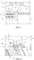
Figure 1 is a section along an axial longitudinal plane of a steam turbine incorporating a stator assembly according to one embodiment of the present invention; -
Figure 2 is a perspective view of an enlarged detail of the steam turbine ofFigure 1 ; -
Figure 3 is a perspective view of the stator assembly ofFigure 1 ; -
Figure 4 is an exploded perspective view of the stator assembly ofFigure 1 ; and -
Figure 5 is a front, partially sectioned view of the stator assembly ofFigure 1 . - With reference to
Figure 1 , a steam turbine, for convenience shown only in part, is indicated with number 1 and comprises ashell 2 and arotor 3, which is housed inside theshell 2 so as to be rotatable around a rotation axis A. Theshell 2 encloses therotor 3 and forms ascroll 4 for receiving steam into aflow path 5 defined between theshell 2 and therotor 3. - The
shell 2 and therotor 3 are respectively provided with arrays ofaxial stator vanes 7 and arrays ofaxial rotor vanes 8, which are arranged in succession along theflow path 5 and form a plurality ofexpansion stages 10 of the axial type. - An
input expansion stage 11, instead, is of the radial-axial type and comprises aradial stator assembly 11a and anaxial rotor assembly 11b. - The
axial rotor assembly 11b comprises an array of axial rotor vanes substantially like those previously described and for this reason indicated with thesame reference number 8. - The
radial stator assembly 11a, which is shown in greater detail inFigures 2-5 , comprises ananchoring ring 13, aguide ring 15 and a plurality oftangential stator vanes 17. - The
anchoring ring 13 and theguide ring 15 are coaxial and thestator vanes 17 each have a respective airfoil 18 (Figures 2 and5 ) connected to respective portions of theanchoring ring 13 and of theguide ring 15. Furthermore, thestator vanes 17 are arranged around the axis of the anchoringring 13 and of the guide ring 15 (Figures 3-5 ) and are configured to tangentially accelerate a steam flow entering from the outside toward the inside of theradial stator assembly 11a. In more detail, the anchoringring 13, theguide ring 15 and thestator vanes 17 define a substantially cylindrical region around the axis of the anchoringring 13 and of the guide ring. In each stator vane 17 (Figure 5 ), theairfoil 18 has aleading edge 18a and a trailingedge 18b extending in a substantially axial direction between the anchoringring 13 and theguide ring 15. Moreover, theairfoil 18 of eachstator vane 17 has aconcave side 18c and aconvex side 18d defined between the respectiveleading edge 18a and therespective trailing edge 18b. Theconcave side 18c faces the outside of the cylindrical region, whereas theconvex side 18d faces the inside of the cylindrical region. The stator vanes 17 are formed in a single piece with the respective portions of the anchoringring 13 and of theguide ring 15. - In one embodiment, the
radial stator assembly 11a is defined by a plurality ofannular sectors 20, each comprising a respective group ofstator vanes 17, an anchoringring sector 13a, and aguide ring sector 15a. The stator vanes 17 of eachannular sector 20 have theairfoil 18 connected to the respectiveanchoring ring sector 13a and to the respectiveguide ring sector 15a. - In one embodiment, in particular, the
radial stator assembly 11a comprises two annular sectors 20 (Figures 3-5 ), each extending over an arc of 180°. The anchoringring sectors 13a and theguide ring sectors 15a also extend over arcs of 180° and each group of stator vanes comprises half of thetotal stator vanes 17. Moreover, eachannular sector 20 is formed in a single piece. In further embodiments, not shown, theradial stator assembly 11a may be divided into a larger number of stator segments, for example three or four. Anyway, each annular sector comprises at least two respective stator vanes. - With reference to
Figure 2 , theshell 2 is provided with an anchoringcircumferential groove 21 and a guidecircumferential groove 22 extending around the rotation axis A. The anchoringring 13 and theguide ring 15 are respectively housed in the anchoringcircumferential groove 21 and the guidecircumferential groove 22. - The anchoring
circumferential groove 21 has a T-shaped cross-section and the anchoringring 13 has abase 13b and aconnection portion 13c projecting from the base 13b towards theguide ring 15. Furthermore, thebase 13b has edges projecting radially inwards and radially outwards with respect to theconnection portion 13c, so that the anchoringring 13 is radially and axially retained inside the anchoringgroove 21. - The guide
circumferential groove 22 may have any cross section, just like the guide ring 15 (for example rectangular). - In use, a steam flow fed to the steam turbine 1 through the
scroll 4 enters theflow path 5 substantially in a radial direction through theradial stator assembly 11a. The steam flow is tangentially accelerated by thestator vanes 17 of theradial stator assembly 11a and is further axially diverted before it reaches theaxial rotor assembly 11b. Thereafter, the steam flow passes through the expansion stages 10 of the steam turbine 1, where part of the available thermodynamic energy is converted into mechanical energy. - The
radial stator assembly 11a may be manufactured (for example and not exclusively) with any subtractive manufacturing technique starting from a semi-finished block in the form of a disk, a cylinder or more generally a plate, made of steel or even a high-nickel alloy. The manufacturing may be carried out, for example, by milling or spark erosion in order to obtain theanchoring ring 13, theguide ring 15, and thestator vanes 17 described above. Alternatively, theradial stator assembly 11a can also be manufactured with additive manufacturing techniques, in any case so that the stator vanes form a single piece with the respective portions of the anchoringring 13 and of theguide ring 15. - The
radial stator assembly 11a is then cut, for example by wire spark erosion, into the desired number of annular sectors (e.g. two, each of 180°). - Lastly, it is evident that the stator assembly described above can be subject to modifications and variations without departing from the scope of the present invention, as defined in the appended claims.
Claims (12)
- A stator assembly for a radial-axial expansion stage of a steam turbine, comprising:an anchoring ring (13) extending around an axis (A);a guide ring (15), extending around the axis (A);a plurality of tangential stator vanes (17), each having a respective airfoil (18) connected to respective portions of the anchoring ring (13) and of the guide ring (15), the stator vanes (17) being arranged around the axis (A) and configured to tangentially accelerate a steam flow entering from the outside toward the inside of the stator assembly;wherein the stator vanes (17) are formed in a single piece with the respective portions of the anchoring ring (13) and of the guide ring (15).
- The stator assembly according to claim 1, comprising a plurality of annular sectors (20), each comprising a respective group of stator vanes (17), an anchoring ring sector (13a) and a guide ring sector (15a), wherein the stator vanes (17) of each annular sector (20) have the respective airfoil (18) connected to the respective anchoring ring sector (13a) and to the respective guide ring sector (15a).
- The stator assembly according to claim 2, comprising two annular sectors (20), each extending over an arc of 180°, wherein each group of stator vanes (17) comprises half of the stator vanes (17) and wherein the anchoring ring sectors (13a) and the guide ring sectors (15a) extend over arcs of 180°.
- The stator assembly according to claim 2 or 3, wherein each annular sector (20) is formed in a single piece.
- The stator assembly according to any one of claims 2 to 4, wherein each annular sector (20) comprises at least two respective stator vanes (17).
- The stator assembly according to any one of the foregoing claims, wherein:the anchoring ring (13), the guide ring (15) and the vanes define a substantially cylindrical region around the axis (A);in each stator vane (17), the airfoil (18) has a leading edge (18a) and a trailing edge (18b) extending between the anchoring ring (13) and the guide ring (15); andthe airfoil (18) of each stator vane (17) has a concave side (18c) facing the outside of the cylindrical region and a convex side (18d) facing the inside of the cylindrical region.
- A steam turbine comprising a radial-axial expansion stage provided with a stator assembly (11a) according to any one of the foregoing claims.
- The steam turbine according to claim 7, comprising a shell (2) housing a rotor (3) rotatable about a rotation axis (A), the shell (2) being provided with an anchoring circumferential groove (21) and a guide circumferential groove (22); wherein the anchoring circumferential groove (21) and the guide circumferential groove (22) extend around the rotation axis (A) and house the anchoring ring (13) and the guide ring (15), respectively.
- The steam turbine according to claim 8, wherein:the anchoring circumferential groove (21) has a T-shaped cross-section and the anchoring ring (13) has a base (13b) and a connection portion (13c) projecting from the base (13b) towards the guide ring (15);the base (13b) has edges projecting radially inwards and radially outwards with respect to the connection portion (13c), and wherein the anchoring ring (13) is radially and axially retained inside the anchoring circumferential groove (21).
- A process for manufacturing a stator assembly of a radial-axial expansion stage of a steam turbine, comprising making:an anchoring ring (13) extending around an axis (A);a guide ring (15), extending around the axis (A);a plurality of tangential stator vanes (17), each having a respective airfoil (18) connected to respective portions of the anchoring ring (13) and of the guide ring (15), the stator vanes (17) being arranged around the axis (A) and configured to tangentially accelerate a steam flow entering from the outside toward the inside of the stator assembly;wherein the stator vanes (17) are formed in a single piece with the respective portions of the anchoring ring (13) and of the guide ring (15).
- The process according to claim 10, comprising obtaining a semi-finished block and making the anchoring ring (13), the guide ring (15) and the plurality of stator vanes (17) by subtractive manufacturing from the semi-finished block.
- The process according to claim 10 or 11, comprising cutting the anchoring ring (13) and the guide ring (15) to form a plurality of annular sectors (20), each comprising a respective group of stator vanes (17), a respective sector of the anchoring ring (13) and a respective sector of the guide ring (15).
Applications Claiming Priority (1)
| Application Number | Priority Date | Filing Date | Title |
|---|---|---|---|
| IT102017000061762A IT201700061762A1 (en) | 2017-06-06 | 2017-06-06 | STATIC GROUP FOR A STAGE OF RADIAL-AXIAL EXPANSION OF STEAM TURBINE |
Publications (2)
| Publication Number | Publication Date |
|---|---|
| EP3412872A1 true EP3412872A1 (en) | 2018-12-12 |
| EP3412872B1 EP3412872B1 (en) | 2020-08-05 |
Family
ID=60294138
Family Applications (1)
| Application Number | Title | Priority Date | Filing Date |
|---|---|---|---|
| EP18176366.5A Active EP3412872B1 (en) | 2017-06-06 | 2018-06-06 | Stator assembly for a radial-axial expansionstage of a steam turbine |
Country Status (2)
| Country | Link |
|---|---|
| EP (1) | EP3412872B1 (en) |
| IT (1) | IT201700061762A1 (en) |
Cited By (3)
| Publication number | Priority date | Publication date | Assignee | Title |
|---|---|---|---|---|
| CN116034211A (en) * | 2020-09-10 | 2023-04-28 | 通用电气公司 | Nozzle arc section, steam turbine with multiple nozzle arc section partitions, and partition assembly method |
| CN119593813A (en) * | 2023-09-08 | 2025-03-11 | 中国航发商用航空发动机有限责任公司 | Assembly method of low pressure turbine stator guide vane |
| TWI923605B (en) | 2020-09-10 | 2026-05-01 | 瑞士商通用電氣技術公司 | Nozzle segment, steam turbine with diaphragm of multiple nozzle segments and method for assembly thereof |
Citations (5)
| Publication number | Priority date | Publication date | Assignee | Title |
|---|---|---|---|---|
| US3802046A (en) * | 1972-01-27 | 1974-04-09 | Chromalloy American Corp | Method of making or reconditioning a turbine-nozzle or the like assembly |
| EP2206902A2 (en) * | 2008-12-23 | 2010-07-14 | General Electric Company | Turbine cooling air from a centrifugal compressor |
| EP2623717A1 (en) * | 2012-02-02 | 2013-08-07 | Siemens Aktiengesellschaft | Blade ring for an axial turbo engine and method for adjusting the absorption characteristics of the blade ring |
| EP2634373A1 (en) * | 2012-02-28 | 2013-09-04 | Siemens Aktiengesellschaft | Arrangement for a turbomachine |
| EP2781696A1 (en) * | 2013-03-19 | 2014-09-24 | ABB Turbo Systems AG | Nozzle ring with non-uniformly distributed airfoils and uniform throat area |
-
2017
- 2017-06-06 IT IT102017000061762A patent/IT201700061762A1/en unknown
-
2018
- 2018-06-06 EP EP18176366.5A patent/EP3412872B1/en active Active
Patent Citations (5)
| Publication number | Priority date | Publication date | Assignee | Title |
|---|---|---|---|---|
| US3802046A (en) * | 1972-01-27 | 1974-04-09 | Chromalloy American Corp | Method of making or reconditioning a turbine-nozzle or the like assembly |
| EP2206902A2 (en) * | 2008-12-23 | 2010-07-14 | General Electric Company | Turbine cooling air from a centrifugal compressor |
| EP2623717A1 (en) * | 2012-02-02 | 2013-08-07 | Siemens Aktiengesellschaft | Blade ring for an axial turbo engine and method for adjusting the absorption characteristics of the blade ring |
| EP2634373A1 (en) * | 2012-02-28 | 2013-09-04 | Siemens Aktiengesellschaft | Arrangement for a turbomachine |
| EP2781696A1 (en) * | 2013-03-19 | 2014-09-24 | ABB Turbo Systems AG | Nozzle ring with non-uniformly distributed airfoils and uniform throat area |
Cited By (5)
| Publication number | Priority date | Publication date | Assignee | Title |
|---|---|---|---|---|
| CN116034211A (en) * | 2020-09-10 | 2023-04-28 | 通用电气公司 | Nozzle arc section, steam turbine with multiple nozzle arc section partitions, and partition assembly method |
| JP2023540686A (en) * | 2020-09-10 | 2023-09-26 | ゼネラル・エレクトリック・カンパニイ | Steam turbine equipped with a nozzle segment, a diaphragm of a plurality of nozzle segments, and its assembly method |
| CN116034211B (en) * | 2020-09-10 | 2025-11-21 | 通用电气维诺瓦技术股份有限公司 | Nozzle arc segment, steam turbine with multiple nozzle arc segment diaphragms and diaphragm assembly method |
| TWI923605B (en) | 2020-09-10 | 2026-05-01 | 瑞士商通用電氣技術公司 | Nozzle segment, steam turbine with diaphragm of multiple nozzle segments and method for assembly thereof |
| CN119593813A (en) * | 2023-09-08 | 2025-03-11 | 中国航发商用航空发动机有限责任公司 | Assembly method of low pressure turbine stator guide vane |
Also Published As
| Publication number | Publication date |
|---|---|
| IT201700061762A1 (en) | 2018-12-06 |
| EP3412872B1 (en) | 2020-08-05 |
Similar Documents
| Publication | Publication Date | Title |
|---|---|---|
| US8720207B2 (en) | Gas turbine stator/rotor expansion stage having bumps arranged to locally increase static pressure | |
| US20170016342A1 (en) | Axial Flow Turbine | |
| US10794224B2 (en) | Gas turbine and method of attaching a turbine nozzle guide vane segment of a gas turbine | |
| US9874101B2 (en) | Platform with curved edges | |
| US9366148B2 (en) | Assembly of an axial turbomachine and method for manufacturing an assembly of this type | |
| EP3192983B1 (en) | Exhaust hood and its flow guide for steam turbine | |
| US9896952B2 (en) | Rotating machine | |
| EP2354449A2 (en) | Method and apparatus for double flow turbine first stage cooling | |
| US9494042B2 (en) | Sealing ring for a turbine stage of an aircraft turbomachine, comprising slotted anti-rotation pegs | |
| US9702259B2 (en) | Turbomachine compressor guide vanes assembly | |
| US11092028B2 (en) | Tip balance slits for turbines | |
| EP3412872B1 (en) | Stator assembly for a radial-axial expansionstage of a steam turbine | |
| EP2649279B1 (en) | Fluid flow machine especially gas turbine penetrated axially by a hot gas stream | |
| US10077662B2 (en) | Rotor for a thermal turbomachine | |
| US10107103B2 (en) | Rotor for a thermal turbomachine | |
| US9546561B2 (en) | Labyrinth disk for a turbomachine | |
| EP2692993B1 (en) | Gas turbine | |
| WO2011151329A1 (en) | Steam turbine assembly and method of assembling a steam turbine | |
| US8545170B2 (en) | Turbo machine efficiency equalizer system | |
| EP3486498B1 (en) | Axial compressor for gas turbine engines and gas turbine engine incorporating said axial compressor | |
| CN111520360B (en) | Mixing rotor with segmented drum | |
| US11313239B2 (en) | Turbmachine fan disc | |
| US9068475B2 (en) | Stator vane assembly | |
| EP3358134B1 (en) | Steam turbine with rotor blade | |
| EP3280880A1 (en) | Two pressure cooling of turbine airfoils |
Legal Events
| Date | Code | Title | Description |
|---|---|---|---|
| PUAI | Public reference made under article 153(3) epc to a published international application that has entered the european phase |
Free format text: ORIGINAL CODE: 0009012 |
|
| STAA | Information on the status of an ep patent application or granted ep patent |
Free format text: STATUS: THE APPLICATION HAS BEEN PUBLISHED |
|
| AK | Designated contracting states |
Kind code of ref document: A1 Designated state(s): AL AT BE BG CH CY CZ DE DK EE ES FI FR GB GR HR HU IE IS IT LI LT LU LV MC MK MT NL NO PL PT RO RS SE SI SK SM TR |
|
| AX | Request for extension of the european patent |
Extension state: BA ME |
|
| STAA | Information on the status of an ep patent application or granted ep patent |
Free format text: STATUS: REQUEST FOR EXAMINATION WAS MADE |
|
| 17P | Request for examination filed |
Effective date: 20190611 |
|
| RBV | Designated contracting states (corrected) |
Designated state(s): AL AT BE BG CH CY CZ DE DK EE ES FI FR GB GR HR HU IE IS IT LI LT LU LV MC MK MT NL NO PL PT RO RS SE SI SK SM TR |
|
| GRAP | Despatch of communication of intention to grant a patent |
Free format text: ORIGINAL CODE: EPIDOSNIGR1 |
|
| STAA | Information on the status of an ep patent application or granted ep patent |
Free format text: STATUS: GRANT OF PATENT IS INTENDED |
|
| INTG | Intention to grant announced |
Effective date: 20200207 |
|
| GRAS | Grant fee paid |
Free format text: ORIGINAL CODE: EPIDOSNIGR3 |
|
| GRAA | (expected) grant |
Free format text: ORIGINAL CODE: 0009210 |
|
| STAA | Information on the status of an ep patent application or granted ep patent |
Free format text: STATUS: THE PATENT HAS BEEN GRANTED |
|
| AK | Designated contracting states |
Kind code of ref document: B1 Designated state(s): AL AT BE BG CH CY CZ DE DK EE ES FI FR GB GR HR HU IE IS IT LI LT LU LV MC MK MT NL NO PL PT RO RS SE SI SK SM TR |
|
| REG | Reference to a national code |
Ref country code: GB Ref legal event code: FG4D |
|
| REG | Reference to a national code |
Ref country code: CH Ref legal event code: EP |
|
| REG | Reference to a national code |
Ref country code: AT Ref legal event code: REF Ref document number: 1298966 Country of ref document: AT Kind code of ref document: T Effective date: 20200815 |
|
| REG | Reference to a national code |
Ref country code: DE Ref legal event code: R096 Ref document number: 602018006573 Country of ref document: DE |
|
| REG | Reference to a national code |
Ref country code: IE Ref legal event code: FG4D |
|
| REG | Reference to a national code |
Ref country code: LT Ref legal event code: MG4D |
|
| REG | Reference to a national code |
Ref country code: NL Ref legal event code: MP Effective date: 20200805 |
|
| REG | Reference to a national code |
Ref country code: AT Ref legal event code: MK05 Ref document number: 1298966 Country of ref document: AT Kind code of ref document: T Effective date: 20200805 |
|
| PG25 | Lapsed in a contracting state [announced via postgrant information from national office to epo] |
Ref country code: LT Free format text: LAPSE BECAUSE OF FAILURE TO SUBMIT A TRANSLATION OF THE DESCRIPTION OR TO PAY THE FEE WITHIN THE PRESCRIBED TIME-LIMIT Effective date: 20200805 Ref country code: HR Free format text: LAPSE BECAUSE OF FAILURE TO SUBMIT A TRANSLATION OF THE DESCRIPTION OR TO PAY THE FEE WITHIN THE PRESCRIBED TIME-LIMIT Effective date: 20200805 Ref country code: FI Free format text: LAPSE BECAUSE OF FAILURE TO SUBMIT A TRANSLATION OF THE DESCRIPTION OR TO PAY THE FEE WITHIN THE PRESCRIBED TIME-LIMIT Effective date: 20200805 Ref country code: SE Free format text: LAPSE BECAUSE OF FAILURE TO SUBMIT A TRANSLATION OF THE DESCRIPTION OR TO PAY THE FEE WITHIN THE PRESCRIBED TIME-LIMIT Effective date: 20200805 Ref country code: PT Free format text: LAPSE BECAUSE OF FAILURE TO SUBMIT A TRANSLATION OF THE DESCRIPTION OR TO PAY THE FEE WITHIN THE PRESCRIBED TIME-LIMIT Effective date: 20201207 Ref country code: ES Free format text: LAPSE BECAUSE OF FAILURE TO SUBMIT A TRANSLATION OF THE DESCRIPTION OR TO PAY THE FEE WITHIN THE PRESCRIBED TIME-LIMIT Effective date: 20200805 Ref country code: NO Free format text: LAPSE BECAUSE OF FAILURE TO SUBMIT A TRANSLATION OF THE DESCRIPTION OR TO PAY THE FEE WITHIN THE PRESCRIBED TIME-LIMIT Effective date: 20201105 Ref country code: GR Free format text: LAPSE BECAUSE OF FAILURE TO SUBMIT A TRANSLATION OF THE DESCRIPTION OR TO PAY THE FEE WITHIN THE PRESCRIBED TIME-LIMIT Effective date: 20201106 Ref country code: BG Free format text: LAPSE BECAUSE OF FAILURE TO SUBMIT A TRANSLATION OF THE DESCRIPTION OR TO PAY THE FEE WITHIN THE PRESCRIBED TIME-LIMIT Effective date: 20201105 Ref country code: AT Free format text: LAPSE BECAUSE OF FAILURE TO SUBMIT A TRANSLATION OF THE DESCRIPTION OR TO PAY THE FEE WITHIN THE PRESCRIBED TIME-LIMIT Effective date: 20200805 |
|
| PG25 | Lapsed in a contracting state [announced via postgrant information from national office to epo] |
Ref country code: RS Free format text: LAPSE BECAUSE OF FAILURE TO SUBMIT A TRANSLATION OF THE DESCRIPTION OR TO PAY THE FEE WITHIN THE PRESCRIBED TIME-LIMIT Effective date: 20200805 Ref country code: PL Free format text: LAPSE BECAUSE OF FAILURE TO SUBMIT A TRANSLATION OF THE DESCRIPTION OR TO PAY THE FEE WITHIN THE PRESCRIBED TIME-LIMIT Effective date: 20200805 Ref country code: NL Free format text: LAPSE BECAUSE OF FAILURE TO SUBMIT A TRANSLATION OF THE DESCRIPTION OR TO PAY THE FEE WITHIN THE PRESCRIBED TIME-LIMIT Effective date: 20200805 Ref country code: LV Free format text: LAPSE BECAUSE OF FAILURE TO SUBMIT A TRANSLATION OF THE DESCRIPTION OR TO PAY THE FEE WITHIN THE PRESCRIBED TIME-LIMIT Effective date: 20200805 Ref country code: IS Free format text: LAPSE BECAUSE OF FAILURE TO SUBMIT A TRANSLATION OF THE DESCRIPTION OR TO PAY THE FEE WITHIN THE PRESCRIBED TIME-LIMIT Effective date: 20201205 |
|
| PG25 | Lapsed in a contracting state [announced via postgrant information from national office to epo] |
Ref country code: EE Free format text: LAPSE BECAUSE OF FAILURE TO SUBMIT A TRANSLATION OF THE DESCRIPTION OR TO PAY THE FEE WITHIN THE PRESCRIBED TIME-LIMIT Effective date: 20200805 Ref country code: DK Free format text: LAPSE BECAUSE OF FAILURE TO SUBMIT A TRANSLATION OF THE DESCRIPTION OR TO PAY THE FEE WITHIN THE PRESCRIBED TIME-LIMIT Effective date: 20200805 Ref country code: CZ Free format text: LAPSE BECAUSE OF FAILURE TO SUBMIT A TRANSLATION OF THE DESCRIPTION OR TO PAY THE FEE WITHIN THE PRESCRIBED TIME-LIMIT Effective date: 20200805 Ref country code: RO Free format text: LAPSE BECAUSE OF FAILURE TO SUBMIT A TRANSLATION OF THE DESCRIPTION OR TO PAY THE FEE WITHIN THE PRESCRIBED TIME-LIMIT Effective date: 20200805 Ref country code: SM Free format text: LAPSE BECAUSE OF FAILURE TO SUBMIT A TRANSLATION OF THE DESCRIPTION OR TO PAY THE FEE WITHIN THE PRESCRIBED TIME-LIMIT Effective date: 20200805 |
|
| REG | Reference to a national code |
Ref country code: DE Ref legal event code: R097 Ref document number: 602018006573 Country of ref document: DE |
|
| PG25 | Lapsed in a contracting state [announced via postgrant information from national office to epo] |
Ref country code: AL Free format text: LAPSE BECAUSE OF FAILURE TO SUBMIT A TRANSLATION OF THE DESCRIPTION OR TO PAY THE FEE WITHIN THE PRESCRIBED TIME-LIMIT Effective date: 20200805 |
|
| PLBE | No opposition filed within time limit |
Free format text: ORIGINAL CODE: 0009261 |
|
| STAA | Information on the status of an ep patent application or granted ep patent |
Free format text: STATUS: NO OPPOSITION FILED WITHIN TIME LIMIT |
|
| PG25 | Lapsed in a contracting state [announced via postgrant information from national office to epo] |
Ref country code: SK Free format text: LAPSE BECAUSE OF FAILURE TO SUBMIT A TRANSLATION OF THE DESCRIPTION OR TO PAY THE FEE WITHIN THE PRESCRIBED TIME-LIMIT Effective date: 20200805 |
|
| 26N | No opposition filed |
Effective date: 20210507 |
|
| PG25 | Lapsed in a contracting state [announced via postgrant information from national office to epo] |
Ref country code: IT Free format text: LAPSE BECAUSE OF FAILURE TO SUBMIT A TRANSLATION OF THE DESCRIPTION OR TO PAY THE FEE WITHIN THE PRESCRIBED TIME-LIMIT Effective date: 20200805 |
|
| PG25 | Lapsed in a contracting state [announced via postgrant information from national office to epo] |
Ref country code: SI Free format text: LAPSE BECAUSE OF FAILURE TO SUBMIT A TRANSLATION OF THE DESCRIPTION OR TO PAY THE FEE WITHIN THE PRESCRIBED TIME-LIMIT Effective date: 20200805 |
|
| PG25 | Lapsed in a contracting state [announced via postgrant information from national office to epo] |
Ref country code: MC Free format text: LAPSE BECAUSE OF FAILURE TO SUBMIT A TRANSLATION OF THE DESCRIPTION OR TO PAY THE FEE WITHIN THE PRESCRIBED TIME-LIMIT Effective date: 20200805 |
|
| REG | Reference to a national code |
Ref country code: CH Ref legal event code: PL |
|
| REG | Reference to a national code |
Ref country code: BE Ref legal event code: MM Effective date: 20210630 |
|
| PG25 | Lapsed in a contracting state [announced via postgrant information from national office to epo] |
Ref country code: LU Free format text: LAPSE BECAUSE OF NON-PAYMENT OF DUE FEES Effective date: 20210606 |
|
| PG25 | Lapsed in a contracting state [announced via postgrant information from national office to epo] |
Ref country code: LI Free format text: LAPSE BECAUSE OF NON-PAYMENT OF DUE FEES Effective date: 20210630 Ref country code: IE Free format text: LAPSE BECAUSE OF NON-PAYMENT OF DUE FEES Effective date: 20210606 Ref country code: CH Free format text: LAPSE BECAUSE OF NON-PAYMENT OF DUE FEES Effective date: 20210630 |
|
| PG25 | Lapsed in a contracting state [announced via postgrant information from national office to epo] |
Ref country code: FR Free format text: LAPSE BECAUSE OF NON-PAYMENT OF DUE FEES Effective date: 20210630 |
|
| PG25 | Lapsed in a contracting state [announced via postgrant information from national office to epo] |
Ref country code: BE Free format text: LAPSE BECAUSE OF NON-PAYMENT OF DUE FEES Effective date: 20210630 |
|
| GBPC | Gb: european patent ceased through non-payment of renewal fee |
Effective date: 20220606 |
|
| PG25 | Lapsed in a contracting state [announced via postgrant information from national office to epo] |
Ref country code: GB Free format text: LAPSE BECAUSE OF NON-PAYMENT OF DUE FEES Effective date: 20220606 |
|
| PG25 | Lapsed in a contracting state [announced via postgrant information from national office to epo] |
Ref country code: CY Free format text: LAPSE BECAUSE OF FAILURE TO SUBMIT A TRANSLATION OF THE DESCRIPTION OR TO PAY THE FEE WITHIN THE PRESCRIBED TIME-LIMIT Effective date: 20200805 |
|
| PG25 | Lapsed in a contracting state [announced via postgrant information from national office to epo] |
Ref country code: HU Free format text: LAPSE BECAUSE OF FAILURE TO SUBMIT A TRANSLATION OF THE DESCRIPTION OR TO PAY THE FEE WITHIN THE PRESCRIBED TIME-LIMIT; INVALID AB INITIO Effective date: 20180606 |
|
| PG25 | Lapsed in a contracting state [announced via postgrant information from national office to epo] |
Ref country code: MK Free format text: LAPSE BECAUSE OF FAILURE TO SUBMIT A TRANSLATION OF THE DESCRIPTION OR TO PAY THE FEE WITHIN THE PRESCRIBED TIME-LIMIT Effective date: 20200805 |
|
| P01 | Opt-out of the competence of the unified patent court (upc) registered |
Effective date: 20240430 |
|
| PG25 | Lapsed in a contracting state [announced via postgrant information from national office to epo] |
Ref country code: TR Free format text: LAPSE BECAUSE OF FAILURE TO SUBMIT A TRANSLATION OF THE DESCRIPTION OR TO PAY THE FEE WITHIN THE PRESCRIBED TIME-LIMIT Effective date: 20200805 |
|
| PG25 | Lapsed in a contracting state [announced via postgrant information from national office to epo] |
Ref country code: MT Free format text: LAPSE BECAUSE OF FAILURE TO SUBMIT A TRANSLATION OF THE DESCRIPTION OR TO PAY THE FEE WITHIN THE PRESCRIBED TIME-LIMIT Effective date: 20200805 |
|
| PGFP | Annual fee paid to national office [announced via postgrant information from national office to epo] |
Ref country code: DE Payment date: 20250618 Year of fee payment: 8 |