EP3412866A1 - Cooled gas turbine blade - Google Patents
Cooled gas turbine blade Download PDFInfo
- Publication number
- EP3412866A1 EP3412866A1 EP17174863.5A EP17174863A EP3412866A1 EP 3412866 A1 EP3412866 A1 EP 3412866A1 EP 17174863 A EP17174863 A EP 17174863A EP 3412866 A1 EP3412866 A1 EP 3412866A1
- Authority
- EP
- European Patent Office
- Prior art keywords
- cooling
- inlet
- discharge
- wall
- blade according
- Prior art date
- Legal status (The legal status is an assumption and is not a legal conclusion. Google has not performed a legal analysis and makes no representation as to the accuracy of the status listed.)
- Granted
Links
Images



Classifications
-
- F—MECHANICAL ENGINEERING; LIGHTING; HEATING; WEAPONS; BLASTING
- F01—MACHINES OR ENGINES IN GENERAL; ENGINE PLANTS IN GENERAL; STEAM ENGINES
- F01D—NON-POSITIVE DISPLACEMENT MACHINES OR ENGINES, e.g. STEAM TURBINES
- F01D5/00—Blades; Blade-carrying members; Heating, heat-insulating, cooling or antivibration means on the blades or the members
- F01D5/12—Blades
- F01D5/14—Form or construction
- F01D5/18—Hollow blades, i.e. blades with cooling or heating channels or cavities; Heating, heat-insulating or cooling means on blades
- F01D5/186—Film cooling
-
- F—MECHANICAL ENGINEERING; LIGHTING; HEATING; WEAPONS; BLASTING
- F01—MACHINES OR ENGINES IN GENERAL; ENGINE PLANTS IN GENERAL; STEAM ENGINES
- F01D—NON-POSITIVE DISPLACEMENT MACHINES OR ENGINES, e.g. STEAM TURBINES
- F01D5/00—Blades; Blade-carrying members; Heating, heat-insulating, cooling or antivibration means on the blades or the members
- F01D5/12—Blades
- F01D5/14—Form or construction
- F01D5/18—Hollow blades, i.e. blades with cooling or heating channels or cavities; Heating, heat-insulating or cooling means on blades
- F01D5/187—Convection cooling
-
- F—MECHANICAL ENGINEERING; LIGHTING; HEATING; WEAPONS; BLASTING
- F05—INDEXING SCHEMES RELATING TO ENGINES OR PUMPS IN VARIOUS SUBCLASSES OF CLASSES F01-F04
- F05D—INDEXING SCHEME FOR ASPECTS RELATING TO NON-POSITIVE-DISPLACEMENT MACHINES OR ENGINES, GAS-TURBINES OR JET-PROPULSION PLANTS
- F05D2250/00—Geometry
- F05D2250/10—Two-dimensional
- F05D2250/18—Two-dimensional patterned
- F05D2250/185—Two-dimensional patterned serpentine-like
-
- F—MECHANICAL ENGINEERING; LIGHTING; HEATING; WEAPONS; BLASTING
- F05—INDEXING SCHEMES RELATING TO ENGINES OR PUMPS IN VARIOUS SUBCLASSES OF CLASSES F01-F04
- F05D—INDEXING SCHEME FOR ASPECTS RELATING TO NON-POSITIVE-DISPLACEMENT MACHINES OR ENGINES, GAS-TURBINES OR JET-PROPULSION PLANTS
- F05D2260/00—Function
- F05D2260/20—Heat transfer, e.g. cooling
- F05D2260/202—Heat transfer, e.g. cooling by film cooling
-
- F—MECHANICAL ENGINEERING; LIGHTING; HEATING; WEAPONS; BLASTING
- F05—INDEXING SCHEMES RELATING TO ENGINES OR PUMPS IN VARIOUS SUBCLASSES OF CLASSES F01-F04
- F05D—INDEXING SCHEME FOR ASPECTS RELATING TO NON-POSITIVE-DISPLACEMENT MACHINES OR ENGINES, GAS-TURBINES OR JET-PROPULSION PLANTS
- F05D2260/00—Function
- F05D2260/20—Heat transfer, e.g. cooling
- F05D2260/204—Heat transfer, e.g. cooling by the use of microcircuits
Definitions
- the present invention relates to a blade for a gas turbine and to an electric power production plant comprising said blade.
- the present invention relates to an improved cooling of the blades of a gas turbine.
- the electric power production plant is connected to an electrical grid.
- the blades of gas turbines are constantly exposed to a hot gas flow coming from the combustion chamber.
- the temperature of the hot gas flowing in the gas turbine affects the performance of the plant.
- performances of the plant increase with an increasing temperature of the hot gas flowing inside the turbine.
- the object of the present invention is therefore to provide a blade having an optimized cooling system, capable of improving the thermal resistance of the blades, allowing a further increase of the temperature of the gases flowing in the gas turbine and reducing the thermodynamic losses thus consequently improving the plant performances.
- a blade for a gas turbine comprising:
- the flow rate of the cooling fluid exiting through the discharge arrangement is properly regulated. While thanks to the fact that the plurality of cooling fluid flows join at the outlet common slot the film cooling efficiency is improved.
- the external face of the outer wall in fact, is lapped by a cooling flow which is wide and homogeneous.
- the discharge arrangement comprises a plurality of connecting channels, each of which is configured to connect a respective hole with the outlet common slot.
- the inlet holes are substantially identical to each other.
- the connecting channels are substantially identical to each other.
- each connecting channel have an inlet section and an outlet section; the inlet section of each connecting channel being in contact with the respective inlet hole and the outlet section of each connecting channel being in contact with the outlet common slot.
- each inlet hole is smaller than the passage area of the inlet section of the respective connecting channels.
- the connecting channels are diverging toward the outlet common slot.
- the passage area of the inlet holes is constant.
- the inlet holes are substantially aligned along a direction which is substantially a straight line extending from a base of the airfoil to a tip of the airfoil.
- the inlet holes are arranged equally spaced from each other.
- the discharge arrangement comprises at least two discharge groups; each discharge group comprises the plurality of inlet holes, the outlet common slot and the plurality of connecting channels.
- the inlet holes of each discharge group are equally spaced one from the other.
- the discharge groups are equally spaced one from the other.
- the present invention relates to a plant for electric power production comprising at least one gas turbine, which extends along a longitudinal axis and comprises at least one row of blades circumferentially spaced and extending radially outwardly from a respective supporting disc of the gas turbine; at least one of the blades of the row being of the type claimed in anyone of the claims 1-12.
- the plant comprises at least one compressor which is connected to the gas turbine by a suction line configured to draw cooling air from the compressor and supply it to the cooling arrangement of the at least one blade.
- reference numeral 1 indicates a gas turbine plant for electrical energy production comprising a compressor 3, a combustor 4, a gas turbine 5 and a generator 7, which transforms the mechanical power supplied by turbine 5 into electrical power to be supplied to an electrical grid 8, connected to the generator 7 via a switch 9.
- plant 1 to be of the combined cycle type and including, in addition to the gas turbine 5 and generator 7, also a steam turbine.
- the gas turbine 5 extends along a longitudinal axis A and is provided with a shaft 10 (also extending along axis A) to which compressor 3 and generator 7 are also connected.
- Gas turbine 5 comprises an expansion channel 12 wherein the hot gas working fluid coming from the combustor 4 flows in a direction D.
- the expansion channel 12 has a section which radially increases along the axis A in the direction D.
- each stage 13 comprises a row of fixed blades and a row of rotating blades (not illustrated in figure 1 ). Each row comprises circumferentially spaced blades extending radially outwardly from a respective supporting disc.
- blade 15 is a rotating blade, but it is clear that the present invention can also be applied to stator blades.
- the blade 15 comprises a root 17, an airfoil 18 and a platform 20.
- the root 17 is configured to be coupled to a supporting disc (not illustrated in the accompanying figures) of the gas turbine 5.
- the disc has a plurality of axial seats, which are circumferentially spaced and engaged by respective roots 17 of the rotating blades 15.
- the airfoil 18 extends from the root 17 and is provided with base 21 coupled to the root 17 and a tip 22 which, in use, is radially opposite to the base 21.
- the airfoil 18 is completely housed in the expansion channel 12 and defines the aerodynamic profile of the rotating blade 15.
- the airfoil 18 has a concave pressure side 24 (better visible in figures 3 and 4 ) and a convex suction side 25, which, in use, extend axially between a leading edge 27 and a trailing edge 28 and radially between the base 21 and the tip 22.
- the leading edge 27 is arranged upstream of the trailing edge 28 along the direction D of the hot working fluid in the expansion channel 12.
- the platform 20 is arranged between the root 17 and the airfoil 18.
- Blade 15 is provided with a cooling arrangement 29.
- the cooling arrangement 29 comprise a plurality of feeding channels 30 made in the root 17 and a plurality of cooling paths 31 (not illustrated in figure 2 and better visible in figures 3 and 4 ) made in the airfoil 18.
- the feeding channels 30 are supplied with a cooling fluid coming from a cooling fluid source 32.
- the cooling fluid source 32 is a portion of the compressor 3.
- a suction line 33 dedicated to the suction of cooling air from the compressor 3 and connected to the gas turbine 5 is shown.
- each feeding channel 30 is coupled to a respective cooling path 31.
- each feeding channels can be coupled to more than one cooling path.
- the feeding channels 30 are four and the cooling paths 31 are four.
- the cooling arrangement 29 comprises a suction side cooling path 31a mainly dedicated to the cooling of the suction side 25, a pressure side cooling path 31b mainly dedicated to the cooling of the pressure side 24, a leading edge cooling path 31c mainly dedicated to the cooling of the leading edge 27 and a trailing edge cooling path 31d mainly dedicated to the cooling of the trailing edge 28.
- a dashed line is used to schematically indicate the cooling path 31a
- a dashed-dotted line is used to schematically indicate the pressure side cooling path 31b
- a dotted line is used to schematically indicate the leading edge cooling path 31c
- a solid line is used to schematically indicate the trailing edge cooling path 31d.
- the airfoil 18 comprises an outer wall 35 and an inner wall 36.
- the outer wall 35 defines at least in part the aerodynamic profile of the blade 15 and has an external face 37 which, in use, is arranged in contact with the hot gas working fluid flowing in the expansion channel 12.
- the inner wall 36 is enclosed by the outer wall 35 and may have cooling and structural functions.
- the inner wall 36 defines an inner central cooling chamber 38, through which, in use, the cooling fluid coming from a respective feeding channel 30 flows as will be detailed in the following.
- the suction side cooling path 31a is defined between the inner wall 36 and the outer wall 35 and extends at least partially along the suction side 25.
- the suction side cooling path 31a comprises at least one inlet 40 (better visible in figure 2 ) and at least one discharge arrangement 41.
- the inlet 40 being arranged closer to the trailing edge 28 than the discharge arrangement 41.
- the suction side cooling path 31a comprises one inlet 40, which is defined by an aperture located at the base 21 of the airfoil 18 and in fluidic communication with the respective feeding channel 30 of the root 17.
- the suction side cooling path 31a comprises one discharge arrangement 41 which will be described in detail later.
- the suction side cooling path 31a comprises a plurality of suction side cooling chambers 42 which are in fluidic communication and arranged side by side between the inner wall 36 and the outer wall 35 along the suction side 25.
- Each of the suction side cooling chambers 42 extends substantially along a direction going from the base 21 toward the tip 22.
- the plurality of suction side cooling chambers 42 comprises a suction side inlet chamber 42a, which is the suction side cooling chamber 42 closest to the trailing edge 28, and a suction side discharge chamber 42b, which is the suction side cooling chamber 42 closest to the leading edge 27.
- the suction side inlet chamber 42a comprises the inlet 40 and the suction side discharge chamber 42b comprises the discharge arrangement 41.
- the suction side cooling path 31a comprises three suction side cooling chambers 42. In other words, between the suction side inlet chamber 42a and the suction side discharge chamber 42b only one suction side intermediate chamber 42c is arranged.
- the cooling fluid coming from the respective feeding channel 30 of the root 17 flows along the suction side inlet chamber 41a, along the suction side intermediate chamber 42c along the suction side discharge chamber 42b and exits through the discharge arrangement 41 of the suction side discharge chamber 42b.
- the flow of the cooling fluid along the suction side cooling path 31a is a counter-current flow with respect to the flow of the hot gas working fluid in the expansion channel 12 having direction D.
- the pressure side cooling path 31b is defined between the inner wall 36 and the outer wall 35 and extends at least partially along the pressure side 24.
- the pressure side cooling path 31b comprises at least one inlet 44 (better visible in figure 2 ) and at least one discharge arrangement 45.
- the discharge arrangement 45 being arranged closer to the trailing edge 28 than the inlet 44.
- the pressure side cooling path 31b comprises one inlet 44, which is defined by an aperture located at the base 21 of the airfoil 18 and in fluidic communication with the respective feeding channel 30 of the root 17.
- the pressure side cooling path 31b comprises two discharge arrangements 45, which will be described in detail later.
- the pressure side cooling path 31b comprises a plurality of pressure side cooling chambers 47 which are in fluidic communication and arranged side by side between the inner wall 36 and the outer wall 35 along the pressure side 24.
- Each of the pressure side cooling chambers 47 extends substantially along a direction going from the base 21 toward the tip 22.
- the plurality of pressure side cooling chambers 47 comprises a pressure side inlet chamber 47a, which is the pressure side cooling chamber 47 closest to the leading edge 27, and at least one pressure side discharge chamber 47b, which is the pressure side cooling chamber 47 closest to the trailing edge 28.
- the pressure side inlet chamber 47a comprises the inlet 44 and the pressure side discharge chamber 47b comprises at least one discharge arrangement 45.
- the pressure side cooling path 31b comprises three pressure side cooling chambers 47: one pressure side inlet chamber 47a and two subsequent discharge chambers 47b, each of which is provided with at least one discharge arrangement 45.
- the cooling fluid coming from the respective feeding channel 30 of the root 17 flows along the pressure side inlet chamber 47a, along the pressure side discharge chamber 47b adjacent to the pressure side inlet chamber 47a and along the pressure side discharge chamber 47b closest to the trailing edge 28 and exits through the two discharge arrangements 45 of the pressure side discharge chambers 47b.
- the flow of the cooling fluid along the pressure side cooling path 31b is a co-current flow with respect to the flow of the hot gas working fluid in the expansion channel 12 having direction D.
- the leading edge cooling path 31c is defined by the inner central cooling chamber 38 and by a leading edge cooling chamber 49 arranged between the inner wall 36 and the outer wall 35 at the leading edge 27.
- the inner central cooling chamber 38 being in fluidic communication with the leading edge cooling chamber 49 by at least one connecting aperture 50.
- the inner central cooling chamber 38 and the leading edge cooling chamber 49 extend substantially along a direction going from the base 21 toward the tip 22.
- the leading edge cooling path 31c comprising at least one inlet 51 (better visible in figure 2 ) and at least one discharge arrangement 53.
- the discharge arrangement 53 being arranged closer to the leading edge 27 than the inlet 51.
- the leading edge cooling path 31c comprises one inlet 51, which is defined by an aperture located at the base 21 of the airfoil 18 and in fluidic communication with the respective feeding channel 30 of the root 17.
- the leading edge cooling path 31c comprises a plurality of discharge arrangements 53, which will be described in detail later.
- the discharge arrangements 53 are at least three: at least one discharge arrangement 53 directed toward the leading edge 27, at least one discharge arrangement 53 directed toward the suction side 25 and at least one discharge arrangement 53 directed toward the pressure side 24.
- leading edge cooling chamber 49 comprises the discharge arrangements 53, while the inner central cooling chamber 38 comprises the inlet 51.
- the cooling fluid coming from the respective feeding channel 30 of the root 17 flows along the inner central cooling chamber 38, through the connecting aperture 50, along leading edge cooling chamber 49 and exits through the discharge arrangements 53 of the leading edge cooling chamber 49.
- the flow of the cooling fluid along the leading edge cooling path 31c is a co-current flow with respect to the flow of the hot gas working fluid in the expansion channel 12 having direction D.
- the trailing edge cooling path 31d is defined by a trailing edge cooling chamber 55 arranged between the inlet 40 of suction side cooling path 31a and the trailing edge 28.
- the trailing edge cooling chamber 55 extends substantially along a direction going from the base 21 toward the tip 22.
- the trailing edge cooling path 31d comprises at least one inlet 57 (better visible in figure 2 ) and at least one discharge arrangement 58.
- the discharge arrangement 58 being arranged on the pressure side 24 and configured to direct the flow toward the trailing edge 28.
- the trailing edge cooling path 31d comprises one inlet 57, which is defined by an aperture located at the base 21 of the airfoil 18 and in fluidic communication with the respective feeding channel 30 of the root 17.
- trailing edge cooling path 31d comprises one discharge arrangement 58, which will be described in detail later.
- the trailing edge cooling chamber 55 comprises the discharge arrangements 58 and the inlet 57.
- the cooling fluid coming from the respective feeding channel 30 of the root 17 flows along the trailing edge cooling chamber 55 and exits through the discharge arrangement 58 toward the trailing edge 28.
- suction side cooling chambers 42, the pressure side cooling chambers 47, the leading edge cooling chamber 49 and the trailing edge cooling chamber 55 can be optionally provided with at least one turbulator in order to improve the cooling effect.
- suction side cooling chambers 42, the pressure side cooling chambers 47 and the trailing edge cooling chamber 55 may comprise turbulators defined by ribs which project from at least one internal face of the respective chamber and are angled with respect to the direction of the cooling fluid inside the chamber.
- said turbulators project from three adjacent internal faces of the respective chamber.
- the leading edge cooling chamber 49 may comprise a plurality of turbulators defined by ribs projecting from at least one internal face of the leading edge cooling chamber 49. Said ribs have a trapezoidal-shaped section. Preferably said turbulators are arranged staggered with respect to the inlet holes of the cooling arrangements 53 at least on the two internal faces of the leading edge cooling chamber 49 which are respectively closest to the pressure side 24 and to the suction side 25.
- the discharging arrangement 41 of the suction side cooling path 31a, the discharge arrangements 45 of the pressure side cooling path 31b, the discharge arrangements 53 of the leading edge cooling path 31c and the discharge arrangement 58 of the trailing edge cooling path 31d have all the structure illustrated in figures 5 and 6 .
- At least one of the discharge arrangement 41 45 53 58 have the structure illustrated in figures 5 and 6 .
- Discharge arrangement 45 extends through the outer wall 35 from the respective internal face of the pressure side discharge cooling chamber 47b to the external face 37 of the outer wall 35.
- the discharge arrangement 45 comprises a plurality of inlet holes 60, an outlet common slot 61 and a plurality of connecting channels 63, each of which is configured to connect a respective hole 60 with the outlet common slot 61.
- the inlet holes 60 are identical to each other.
- the connecting channels 63 are identical to each other.
- the connecting channels 63 are diverging toward the outlet common slot 61.
- the connecting channels 63 have a passage area which gradually increases toward the outlet common slot 61.
- the increase of the passage area starts from an inlet section 65 of the connecting channels 63 and ends at an outlet section 66 of the connecting channels 63.
- the inlet section 65 of each connecting channel 63 being in contact with the respective inlet hole 60 and the outlet section 66 of each connecting channel 63 being in contact with the outlet common slot 61.
- the passage area of the inlet holes 60 is constant.
- the passage area of the inlet hole 60 is smaller than the passage area of the inlet section 65 of the respective connecting channels 63.
- the passage area of the inlet section 65 of the respective connecting channels 63 is 10-20% greater than the passage area of the inlet hole 60.
- the area ratio between inlet section 65 and outlet section 66 of the connecting channels 63 is comprised between 3,5 to 5.
- the inlet holes 60 are substantially aligned along a direction F on the respective internal face of the pressure side discharge cooling chamber 47b.
- the inlet holes 60 are arranged equally spaced from each other.
- the outlet common slot 61 is substantially aligned along a direction parallel to direction F.
- Direction F is substantially a straight line extending from the base 21 to tip 22 of the airfoil 18.
- the discharge arrangement 45 extends along a main axis G which is inclined with respect to the external face 37 of the outer wall with an angle ⁇ .
- the inlet holes 60 and the connecting channels 63 and the outlet common slot 61 extends along said main axis G as shown in the cross section of figure 5 .
- the depth DH of the inlet holes 60 is 10-20% of the total depth Dtot of the outer wall 35; wherein both depth DH and depth Dtot are measured along the main axis G.
- the depth DC of the connecting channels 63 is 50%-70% of the total depth Dtot of the outer wall 35; wherein both depth DC and depth Dtot are measured along the main axis G.
- Depth DS of the outlet common slot 61 is 20-30% of the total depth Dtot of the outer wall 35; wherein both depth DS and depth Dtot are measured along the main axis G.
- angle ⁇ of inclination and the total depth of the outer wall 35 measured along the main axis G can be different for each one of the discharge arrangements 41 45 53 58.
- the angle ⁇ of discharge arrangement 58 is equal or greater than the angle ⁇ of discharge arrangement 45.
- the cooling fluid coming from the respective pressure side discharge cooling chamber 47b is divided by the plurality of inlet holes 60, flows into the respective connecting channels 63 and joins at the outlet common slot 61.
- a single wide and homogenous flow of cooling fluid exits from the outlet common slot 61 as indicated also by the arrow in figure 6 .
- outlet common slot 61 improves the film cooling efficiency as the external face 37 of the outer wall 35 is lapped by a cooling flow which is wide and homogeneous.
- FIG 7 a further embodiment of the discharge arrangement 145 is illustrated.
- the same reference numbers used for the cooling arrangement 45 of figures 5 and 6 are used also in figure 7 for indicating similar or identical parts.
- the discharge arrangement 145 comprises at least two discharge groups 146
- the discharge arrangement 145 comprises three discharge groups 146.
- Each discharge group 146 comprises a plurality of inlet holes 160, an outlet common slot 161 and a plurality of connecting channels 163, each of which is configured to connect a respective hole 160 with the outlet common slot 161.
- each connecting channel 163 have an inlet section 165 and an outlet section 166; the inlet section 165 of each connecting channel 163 being in contact with the respective inlet hole 160 and the outlet section 166 of each connecting channel 163 being in contact with the outlet common slot 161.
- the passage area of each inlet hole 160 is preferably smaller than the passage area of the inlet section 165 of the respective connecting channels 163 analogously to the embodiment illustrated in figure 6 .
- each discharge group 146 comprises a three inlet holes 160, an outlet common slot 161 and three connecting channels 163, each of which is configured to connect a respective hole 160 with the outlet common slot 161.
- the inlet holes 160 of each group 146 are equally spaced one from the other.
- the discharge groups 146 are spaced one from the other. Preferably the discharge groups 146 are equally spaced one from the other.
- cooling fluid coming from the respective pressure side discharge cooling chamber 47b is divided by the plurality of inlet holes 160, flows into the respective connecting channels 163 and joins at the outlet common slots 161.
- three homogenous flows of cooling fluid exits from the outlet common slots 161 as indicated also by the arrows in figure 7 .
Landscapes
- Engineering & Computer Science (AREA)
- Mechanical Engineering (AREA)
- General Engineering & Computer Science (AREA)
- Turbine Rotor Nozzle Sealing (AREA)
Abstract
Description
- The present invention relates to a blade for a gas turbine and to an electric power production plant comprising said blade. In particular, the present invention relates to an improved cooling of the blades of a gas turbine. Preferably the electric power production plant is connected to an electrical grid.
- During the operation of the electrical energy production plants, the blades of gas turbines are constantly exposed to a hot gas flow coming from the combustion chamber.
- The temperature of the hot gas flowing in the gas turbine affects the performance of the plant. In particular, performances of the plant increase with an increasing temperature of the hot gas flowing inside the turbine.
- However, the increase of the temperature of the hot gas flowing in the gas turbine is limited by the thermal resistance of the material constituting the blades.
- To overcome this kind of limitation, in recent years, a cooling system for the blades has been adopted. Normally cooling air extracted from the compressor or coming from a dedicated cooling air source is driven through the blades.
- Examples of blades provided with a cooling system are disclosed in documents
US 8,231,349 orEP 2107215 . - However, introducing a large amount of cooling air into the blades of the gas turbine would lead to excessive thermodynamic losses.
- The object of the present invention is therefore to provide a blade having an optimized cooling system, capable of improving the thermal resistance of the blades, allowing a further increase of the temperature of the gases flowing in the gas turbine and reducing the thermodynamic losses thus consequently improving the plant performances.
- According to the present invention, there is provided a blade for a gas turbine comprising:
- an airfoil having a leading edge, a trailing edge, a pressure side and a suction side; the airfoil comprising an outer wall and an inner wall substantially enclosed by the outer wall; and
- a cooling arrangement which comprises at least one cooling path between the outer wall and the inner wall; the cooling path having at least one inlet and at least one discharge arrangement; wherein the discharge arrangement extends through the outer wall and comprises a plurality of inlet holes and at least one outlet common slot.
- Thanks to the presence of a plurality of inlet holes having a defined passage area the flow rate of the cooling fluid exiting through the discharge arrangement is properly regulated. While thanks to the fact that the plurality of cooling fluid flows join at the outlet common slot the film cooling efficiency is improved. The external face of the outer wall, in fact, is lapped by a cooling flow which is wide and homogeneous.
- As the efficiency of the cooling is increased, a lower cooling fluid flow rate can be drawn for cooling the blades. This lead to a significant increase in the efficiency of the plant as the cooling fluid is normally drawn from the compressor of the plant.
- According to a preferred embodiment of the present invention, the discharge arrangement comprises a plurality of connecting channels, each of which is configured to connect a respective hole with the outlet common slot.
- According to a preferred embodiment of the present invention, the inlet holes are substantially identical to each other.
- According to a preferred embodiment of the present invention, the connecting channels are substantially identical to each other.
- According to a preferred embodiment of the present invention, each connecting channel have an inlet section and an outlet section; the inlet section of each connecting channel being in contact with the respective inlet hole and the outlet section of each connecting channel being in contact with the outlet common slot.
- According to a preferred embodiment of the present invention, the passage area of each inlet hole is smaller than the passage area of the inlet section of the respective connecting channels.
- According to a preferred embodiment of the present invention, the connecting channels are diverging toward the outlet common slot.
- According to a preferred embodiment of the present invention, the passage area of the inlet holes is constant.
- According to a preferred embodiment of the present invention, the inlet holes are substantially aligned along a direction which is substantially a straight line extending from a base of the airfoil to a tip of the airfoil.
- According to a preferred embodiment of the present invention, the inlet holes are arranged equally spaced from each other.
- According to a preferred embodiment of the present invention, the discharge arrangement comprises at least two discharge groups; each discharge group comprises the plurality of inlet holes, the outlet common slot and the plurality of connecting channels.
- According to a preferred embodiment of the present invention, the inlet holes of each discharge group are equally spaced one from the other.
- According to a preferred embodiment of the present invention, the discharge groups are equally spaced one from the other.
- It is furthermore another object of the present invention to provide a plant for electric power production having an improved power efficiency.
- According to said object the present invention relates to a plant for electric power production comprising at least one gas turbine, which extends along a longitudinal axis and comprises at least one row of blades circumferentially spaced and extending radially outwardly from a respective supporting disc of the gas turbine; at least one of the blades of the row being of the type claimed in anyone of the claims 1-12.
- According to a preferred embodiment of the present invention, the plant comprises at least one compressor which is connected to the gas turbine by a suction line configured to draw cooling air from the compressor and supply it to the cooling arrangement of the at least one blade.
- The present invention will now be described with reference to the accompanying drawings, which illustrate some non-limitative embodiment, in which:
-
Figure 1 is a schematic lateral representation, with parts removed for clarity and parts in section, of an electric power production plant comprising according to the present invention; -
Figure 2 is a schematic lateral view, with parts removed for clarity and parts in section, of a blade for a gas turbine according to the present invention; -
Figure 3 is a schematic perspective view, with parts removed for clarity and parts in section, of a first detail of the blade offigure 2 ; -
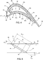
Figure 4 is a top section view of the first detail of the blade offigure 2 ; -
Figure 5 is an enlarged schematic section view of a second detail of the blade according to the present invention. -
Figure 6 is a schematic section view of the second detail along plane VI-VI indicated infigure 5 ; -
Figure 7 is a schematic section view of the second detail along plane VI-VI indicated infigure 5 according to a further embodiment of the present invention. - In
figure 1 ,reference numeral 1 indicates a gas turbine plant for electrical energy production comprising acompressor 3, acombustor 4, agas turbine 5 and agenerator 7, which transforms the mechanical power supplied byturbine 5 into electrical power to be supplied to anelectrical grid 8, connected to thegenerator 7 via aswitch 9. - A variant not shown provides for
plant 1 to be of the combined cycle type and including, in addition to thegas turbine 5 andgenerator 7, also a steam turbine. - The
gas turbine 5 extends along a longitudinal axis A and is provided with a shaft 10 (also extending along axis A) to whichcompressor 3 andgenerator 7 are also connected. -
Gas turbine 5 comprises anexpansion channel 12 wherein the hot gas working fluid coming from thecombustor 4 flows in a direction D. - The
expansion channel 12 has a section which radially increases along the axis A in the direction D. - In the expansion channel 12 a plurality of
stages 13 spaced along the longitudinal axis A is arranged. Eachstage 13 comprises a row of fixed blades and a row of rotating blades (not illustrated infigure 1 ). Each row comprises circumferentially spaced blades extending radially outwardly from a respective supporting disc. - In
figure 2 a blade 15 of astage 13 of thegas turbine 5 is represented. - Preferably, blade 15 is a rotating blade, but it is clear that the present invention can also be applied to stator blades.
- The blade 15 comprises a
root 17, anairfoil 18 and aplatform 20. - The
root 17 is configured to be coupled to a supporting disc (not illustrated in the accompanying figures) of thegas turbine 5. In particular, the disc has a plurality of axial seats, which are circumferentially spaced and engaged byrespective roots 17 of the rotating blades 15. - The
airfoil 18 extends from theroot 17 and is provided withbase 21 coupled to theroot 17 and atip 22 which, in use, is radially opposite to thebase 21. - The
airfoil 18 is completely housed in theexpansion channel 12 and defines the aerodynamic profile of the rotating blade 15. - The
airfoil 18 has a concave pressure side 24 (better visible infigures 3 and4 ) and aconvex suction side 25, which, in use, extend axially between a leadingedge 27 and atrailing edge 28 and radially between thebase 21 and thetip 22. - The leading
edge 27 is arranged upstream of thetrailing edge 28 along the direction D of the hot working fluid in theexpansion channel 12. - The
platform 20 is arranged between theroot 17 and theairfoil 18. - Blade 15 is provided with a cooling arrangement 29. The cooling arrangement 29 comprise a plurality of feeding
channels 30 made in theroot 17 and a plurality of cooling paths 31 (not illustrated infigure 2 and better visible infigures 3 and4 ) made in theairfoil 18. - The feeding
channels 30 are supplied with a cooling fluid coming from a coolingfluid source 32. - Preferably, the cooling
fluid source 32 is a portion of thecompressor 3. Infigure 1 asuction line 33 dedicated to the suction of cooling air from thecompressor 3 and connected to thegas turbine 5 is shown. - Preferably, each feeding
channel 30 is coupled to a respective cooling path 31. According to a variant not shown each feeding channels can be coupled to more than one cooling path. - In the non-limiting embodiment here disclosed and illustrated, the feeding
channels 30 are four and the cooling paths 31 are four. - With reference to
figure 3 , the cooling arrangement 29 comprises a suctionside cooling path 31a mainly dedicated to the cooling of thesuction side 25, a pressureside cooling path 31b mainly dedicated to the cooling of thepressure side 24, a leadingedge cooling path 31c mainly dedicated to the cooling of the leadingedge 27 and a trailingedge cooling path 31d mainly dedicated to the cooling of the trailingedge 28. - In
figure 3 a dashed line is used to schematically indicate thecooling path 31a, a dashed-dotted line is used to schematically indicate the pressureside cooling path 31b, a dotted line is used to schematically indicate the leadingedge cooling path 31c, a solid line is used to schematically indicate the trailingedge cooling path 31d. - The
airfoil 18 comprises anouter wall 35 and aninner wall 36. - The
outer wall 35 defines at least in part the aerodynamic profile of the blade 15 and has anexternal face 37 which, in use, is arranged in contact with the hot gas working fluid flowing in theexpansion channel 12. - The
inner wall 36 is enclosed by theouter wall 35 and may have cooling and structural functions. - In particular the
inner wall 36 defines an innercentral cooling chamber 38, through which, in use, the cooling fluid coming from arespective feeding channel 30 flows as will be detailed in the following. - The suction
side cooling path 31a is defined between theinner wall 36 and theouter wall 35 and extends at least partially along thesuction side 25. - The suction
side cooling path 31a comprises at least one inlet 40 (better visible infigure 2 ) and at least onedischarge arrangement 41. - The
inlet 40 being arranged closer to the trailingedge 28 than thedischarge arrangement 41. - In the non-limiting embodiment here disclosed and illustrated, the suction
side cooling path 31a comprises oneinlet 40, which is defined by an aperture located at thebase 21 of theairfoil 18 and in fluidic communication with therespective feeding channel 30 of theroot 17. - In the non-limiting embodiment here disclosed and illustrated, the suction
side cooling path 31a comprises onedischarge arrangement 41 which will be described in detail later. - In more detail, the suction
side cooling path 31a comprises a plurality of suction side cooling chambers 42 which are in fluidic communication and arranged side by side between theinner wall 36 and theouter wall 35 along thesuction side 25. - Each of the suction side cooling chambers 42 extends substantially along a direction going from the base 21 toward the
tip 22. - The plurality of suction side cooling chambers 42 comprises a suction
side inlet chamber 42a, which is the suction side cooling chamber 42 closest to the trailingedge 28, and a suctionside discharge chamber 42b, which is the suction side cooling chamber 42 closest to the leadingedge 27. - The suction
side inlet chamber 42a comprises theinlet 40 and the suctionside discharge chamber 42b comprises thedischarge arrangement 41. - In the non-limiting embodiment here disclosed and illustrated, the suction
side cooling path 31a comprises three suction side cooling chambers 42. In other words, between the suctionside inlet chamber 42a and the suctionside discharge chamber 42b only one suction sideintermediate chamber 42c is arranged. - In use, the cooling fluid coming from the
respective feeding channel 30 of theroot 17 flows along the suction side inlet chamber 41a, along the suction sideintermediate chamber 42c along the suctionside discharge chamber 42b and exits through thedischarge arrangement 41 of the suctionside discharge chamber 42b. - In other words, the flow of the cooling fluid along the suction
side cooling path 31a is a counter-current flow with respect to the flow of the hot gas working fluid in theexpansion channel 12 having direction D. - The pressure
side cooling path 31b is defined between theinner wall 36 and theouter wall 35 and extends at least partially along thepressure side 24. - The pressure
side cooling path 31b comprises at least one inlet 44 (better visible infigure 2 ) and at least onedischarge arrangement 45. - The
discharge arrangement 45 being arranged closer to the trailingedge 28 than theinlet 44. - In the non-limiting embodiment here disclosed and illustrated, the pressure
side cooling path 31b comprises oneinlet 44, which is defined by an aperture located at thebase 21 of theairfoil 18 and in fluidic communication with therespective feeding channel 30 of theroot 17. - In the non-limiting embodiment here disclosed and illustrated, the pressure
side cooling path 31b comprises twodischarge arrangements 45, which will be described in detail later. - In more detail, the pressure
side cooling path 31b comprises a plurality of pressure side cooling chambers 47 which are in fluidic communication and arranged side by side between theinner wall 36 and theouter wall 35 along thepressure side 24. - Each of the pressure side cooling chambers 47 extends substantially along a direction going from the base 21 toward the
tip 22. - The plurality of pressure side cooling chambers 47 comprises a pressure
side inlet chamber 47a, which is the pressure side cooling chamber 47 closest to the leadingedge 27, and at least one pressureside discharge chamber 47b, which is the pressure side cooling chamber 47 closest to the trailingedge 28. - The pressure
side inlet chamber 47a comprises theinlet 44 and the pressureside discharge chamber 47b comprises at least onedischarge arrangement 45. - In the non-limiting embodiment here disclosed and illustrated, the pressure
side cooling path 31b comprises three pressure side cooling chambers 47: one pressureside inlet chamber 47a and twosubsequent discharge chambers 47b, each of which is provided with at least onedischarge arrangement 45. - In use, the cooling fluid coming from the
respective feeding channel 30 of theroot 17 flows along the pressureside inlet chamber 47a, along the pressureside discharge chamber 47b adjacent to the pressureside inlet chamber 47a and along the pressureside discharge chamber 47b closest to the trailingedge 28 and exits through the twodischarge arrangements 45 of the pressureside discharge chambers 47b. - In other words, the flow of the cooling fluid along the pressure
side cooling path 31b is a co-current flow with respect to the flow of the hot gas working fluid in theexpansion channel 12 having direction D. - The leading
edge cooling path 31c is defined by the innercentral cooling chamber 38 and by a leadingedge cooling chamber 49 arranged between theinner wall 36 and theouter wall 35 at theleading edge 27. The innercentral cooling chamber 38 being in fluidic communication with the leadingedge cooling chamber 49 by at least one connectingaperture 50. - The inner
central cooling chamber 38 and the leadingedge cooling chamber 49 extend substantially along a direction going from the base 21 toward thetip 22. - The leading
edge cooling path 31c comprising at least one inlet 51 (better visible infigure 2 ) and at least onedischarge arrangement 53. - The
discharge arrangement 53 being arranged closer to the leadingedge 27 than theinlet 51. - In the non-limiting embodiment here disclosed and illustrated, the leading
edge cooling path 31c comprises oneinlet 51, which is defined by an aperture located at thebase 21 of theairfoil 18 and in fluidic communication with therespective feeding channel 30 of theroot 17. - In the non-limiting embodiment here disclosed and the leading
edge cooling path 31c comprises a plurality ofdischarge arrangements 53, which will be described in detail later. Preferably thedischarge arrangements 53 are at least three: at least onedischarge arrangement 53 directed toward the leadingedge 27, at least onedischarge arrangement 53 directed toward thesuction side 25 and at least onedischarge arrangement 53 directed toward thepressure side 24. - In more detail, the leading
edge cooling chamber 49 comprises thedischarge arrangements 53, while the innercentral cooling chamber 38 comprises theinlet 51. - In use, the cooling fluid coming from the
respective feeding channel 30 of theroot 17 flows along the innercentral cooling chamber 38, through the connectingaperture 50, along leadingedge cooling chamber 49 and exits through thedischarge arrangements 53 of the leadingedge cooling chamber 49. - In other words, the flow of the cooling fluid along the leading
edge cooling path 31c is a co-current flow with respect to the flow of the hot gas working fluid in theexpansion channel 12 having direction D. - The trailing
edge cooling path 31d is defined by a trailingedge cooling chamber 55 arranged between theinlet 40 of suctionside cooling path 31a and the trailingedge 28. - The trailing
edge cooling chamber 55 extends substantially along a direction going from the base 21 toward thetip 22. - The trailing
edge cooling path 31d comprises at least one inlet 57 (better visible infigure 2 ) and at least onedischarge arrangement 58. - The
discharge arrangement 58 being arranged on thepressure side 24 and configured to direct the flow toward the trailingedge 28. - In the non-limiting embodiment here disclosed and illustrated, the trailing
edge cooling path 31d comprises oneinlet 57, which is defined by an aperture located at thebase 21 of theairfoil 18 and in fluidic communication with therespective feeding channel 30 of theroot 17. - In the non-limiting embodiment here disclosed and illustrated the trailing
edge cooling path 31d comprises onedischarge arrangement 58, which will be described in detail later. - In more detail, the trailing
edge cooling chamber 55 comprises thedischarge arrangements 58 and theinlet 57. - In use, the cooling fluid coming from the
respective feeding channel 30 of theroot 17 flows along the trailingedge cooling chamber 55 and exits through thedischarge arrangement 58 toward the trailingedge 28. - The suction side cooling chambers 42, the pressure side cooling chambers 47, the leading
edge cooling chamber 49 and the trailingedge cooling chamber 55 can be optionally provided with at least one turbulator in order to improve the cooling effect. - In particular, the suction side cooling chambers 42, the pressure side cooling chambers 47 and the trailing
edge cooling chamber 55 may comprise turbulators defined by ribs which project from at least one internal face of the respective chamber and are angled with respect to the direction of the cooling fluid inside the chamber. - Preferably said turbulators project from three adjacent internal faces of the respective chamber.
- The leading
edge cooling chamber 49 may comprise a plurality of turbulators defined by ribs projecting from at least one internal face of the leadingedge cooling chamber 49. Said ribs have a trapezoidal-shaped section. Preferably said turbulators are arranged staggered with respect to the inlet holes of the coolingarrangements 53 at least on the two internal faces of the leadingedge cooling chamber 49 which are respectively closest to thepressure side 24 and to thesuction side 25. - In
figures 5 and6 the shape of a discharging arrangement is illustrated. - Preferably, the discharging
arrangement 41 of the suctionside cooling path 31a, thedischarge arrangements 45 of the pressureside cooling path 31b, thedischarge arrangements 53 of the leadingedge cooling path 31c and thedischarge arrangement 58 of the trailingedge cooling path 31d have all the structure illustrated infigures 5 and6 . - According to a variant not illustrated, at least one of the
discharge arrangement 41 45 53 58 have the structure illustrated infigures 5 and6 . - In
figure 5 and6 only thedischarge arrangement 45 is illustrated. However, as the structure of the remainingdischarge arrangements 41 53 58 is substantially identical to the structure of thedischarge arrangement 45, the following considerations can be considered valid also for thedischarge arrangements 41 53 58. -
Discharge arrangement 45 extends through theouter wall 35 from the respective internal face of the pressure side discharge coolingchamber 47b to theexternal face 37 of theouter wall 35. - With reference to
figure 6 , thedischarge arrangement 45 comprises a plurality of inlet holes 60, an outletcommon slot 61 and a plurality of connectingchannels 63, each of which is configured to connect arespective hole 60 with the outletcommon slot 61. - Preferably the inlet holes 60 are identical to each other.
- Preferably the connecting
channels 63 are identical to each other. - The connecting
channels 63 are diverging toward the outletcommon slot 61. In other words, the connectingchannels 63 have a passage area which gradually increases toward the outletcommon slot 61. - The increase of the passage area starts from an
inlet section 65 of the connectingchannels 63 and ends at an outlet section 66 of the connectingchannels 63. Theinlet section 65 of each connectingchannel 63 being in contact with therespective inlet hole 60 and the outlet section 66 of each connectingchannel 63 being in contact with the outletcommon slot 61. - The passage area of the inlet holes 60 is constant.
- As better visible in
figure 5 , the passage area of theinlet hole 60 is smaller than the passage area of theinlet section 65 of the respective connectingchannels 63. - In the non-limiting example here disclosed and illustrated the passage area of the
inlet section 65 of the respective connectingchannels 63 is 10-20% greater than the passage area of theinlet hole 60. - Moreover, in the non-limiting example here disclosed and illustrated, the area ratio between
inlet section 65 and outlet section 66 of the connectingchannels 63 is comprised between 3,5 to 5. - Preferably, the inlet holes 60 are substantially aligned along a direction F on the respective internal face of the pressure side discharge cooling
chamber 47b. Preferably, the inlet holes 60 are arranged equally spaced from each other. - Preferably, the outlet
common slot 61 is substantially aligned along a direction parallel to direction F. - Direction F is substantially a straight line extending from the base 21 to tip 22 of the
airfoil 18. - With reference to
figure 5 , thedischarge arrangement 45 extends along a main axis G which is inclined with respect to theexternal face 37 of the outer wall with an angle α. - In other words, the inlet holes 60 and the connecting
channels 63 and the outletcommon slot 61 extends along said main axis G as shown in the cross section offigure 5 . - The depth DH of the inlet holes 60 is 10-20% of the total depth Dtot of the
outer wall 35; wherein both depth DH and depth Dtot are measured along the main axis G. - The depth DC of the connecting
channels 63 is 50%-70% of the total depth Dtot of theouter wall 35; wherein both depth DC and depth Dtot are measured along the main axis G. - Depth DS of the outlet
common slot 61 is 20-30% of the total depth Dtot of theouter wall 35; wherein both depth DS and depth Dtot are measured along the main axis G. - Obviously the angle α of inclination and the total depth of the
outer wall 35 measured along the main axis G can be different for each one of thedischarge arrangements 41 45 53 58. - In the non-limiting example here disclosed and illustrated, the angle α of
discharge arrangement 58 is equal or greater than the angle α ofdischarge arrangement 45. - In use, the cooling fluid coming from the respective pressure side discharge cooling
chamber 47b is divided by the plurality of inlet holes 60, flows into the respective connectingchannels 63 and joins at the outletcommon slot 61. A single wide and homogenous flow of cooling fluid exits from the outletcommon slot 61 as indicated also by the arrow infigure 6 . - The presence of a plurality of inlet holes 60 having a defined passage area regulates the flow rate of the cooling fluid exiting through the
discharge arrangement 45. - The presence of an outlet
common slot 61 improves the film cooling efficiency as theexternal face 37 of theouter wall 35 is lapped by a cooling flow which is wide and homogeneous. - Due to the increased cooling efficiency lower amounts of cooling air is required for the blade. Due to this the overall efficiency of the gas turbine is increased.
- In
figure 7 a further embodiment of thedischarge arrangement 145 is illustrated. The same reference numbers used for thecooling arrangement 45 offigures 5 and6 are used also infigure 7 for indicating similar or identical parts. - According to said embodiment, the
discharge arrangement 145 comprises at least twodischarge groups 146 - In the non-limiting example here disclosed and illustrated, the
discharge arrangement 145 comprises threedischarge groups 146. - Each
discharge group 146 comprises a plurality of inlet holes 160, an outletcommon slot 161 and a plurality of connectingchannels 163, each of which is configured to connect arespective hole 160 with the outletcommon slot 161. - In particular, each connecting
channel 163 have an inlet section 165 and an outlet section 166; the inlet section 165 of each connectingchannel 163 being in contact with therespective inlet hole 160 and the outlet section 166 of each connectingchannel 163 being in contact with the outletcommon slot 161. The passage area of eachinlet hole 160 is preferably smaller than the passage area of the inlet section 165 of the respective connectingchannels 163 analogously to the embodiment illustrated infigure 6 . - In the non-limiting example here disclosed and illustrated, each
discharge group 146 comprises a threeinlet holes 160, an outletcommon slot 161 and three connectingchannels 163, each of which is configured to connect arespective hole 160 with the outletcommon slot 161. - The inlet holes 160 of each
group 146 are equally spaced one from the other. - The
discharge groups 146 are spaced one from the other. Preferably thedischarge groups 146 are equally spaced one from the other. - In use the cooling fluid coming from the respective pressure side discharge cooling
chamber 47b is divided by the plurality of inlet holes 160, flows into the respective connectingchannels 163 and joins at the outletcommon slots 161. In the non-limiting example here disclosed and illustrated, three homogenous flows of cooling fluid exits from the outletcommon slots 161 as indicated also by the arrows infigure 7 . - Finally, it is clear that modifications and variants can be made to the blade and the gas turbine described herein without departing from the scope of the present invention, as defined in the appended claims.
Claims (15)
- Blade for a gas turbine (5) comprising:an airfoil (18) having a leading edge (27), a trailing edge (28), a pressure side (24) and a suction side (25);the airfoil (18) comprising an outer wall (30) and an inner wall (31) substantially enclosed by the outer wall (30); anda cooling arrangement (29) which comprises at least one cooling path (31a; 31b; 31c; 31d) between the outer wall (30) and the inner wall (31); the cooling path (31a; 31b; 31c; 31d) having at least one inlet (40; 44; 51; 57) and at least one discharge arrangement (41; 45; 53; 58);wherein the discharge arrangement (41; 45; 53; 58) extends through the outer wall (35) and comprises a plurality of inlet holes (60; 160)and at least one outlet common slot (61; 161).
- Blade according to claim 1, wherein the discharge arrangement comprises a plurality of connecting channels (63; 163), each of which is configured to connect a respective hole (60;160) with the outlet common slot (61; 161).
- Blade according to claim 2, wherein the inlet holes (60; 160) are substantially identical to each other.
- Blade according to claim 2, wherein the connecting channels (63; 163) are substantially identical to each other.
- Blade according to anyone of the claims 2-4, wherein each connecting channel (63; 163) have an inlet section (65; 165) and an outlet section (66; 166); the inlet section (65; 165) of each connecting channel (63; 163) being in contact with the respective inlet hole (60; 160) and the outlet section (66; 166) of each connecting channel (63; 163) being in contact with the outlet common slot (61; 161).
- Blade according to claim 5, wherein the passage area of each inlet hole (60; 160) is smaller than the passage area of the inlet section (65; 165) of the respective connecting channels (63; 163).
- Blade according to anyone of the claims 2-6, wherein the connecting channels (63; 163) are diverging toward the outlet common slot (61; 161).
- Blade according to anyone of the foregoing claims, wherein the passage area of the inlet holes (60; 160) is constant.
- Blade according to anyone of the foregoing claims, wherein the inlet holes (60; 160) are substantially aligned along a direction (F) which is substantially a straight line extending from a base (21) of the airfoil (18) to a tip (22) of the airfoil (18).
- Blade according to claim 9, wherein the inlet holes (60) are arranged equally spaced from each other.
- Blade according to anyone of the claims 2-10, wherein the discharge arrangement (145) comprises at least two discharge groups (146); each discharge group (146) comprises the plurality of inlet holes (160), the outlet common slot (161) and the plurality of connecting channels (163).
- Blade according to claim 11, wherein the inlet holes (160) of each discharge group (146) are equally spaced one from the other.
- Blade according to claim 11 or 12, wherein the discharge groups (146) are equally spaced one from the other.
- Plant for electric power production comprising at least one gas turbine (5), which extends along a longitudinal axis (A) and comprises at least one row of blades (15) circumferentially spaced and extending radially outwardly from a respective supporting disc of the gas turbine (5); at least one of the blades (15) of the row being of the type claimed in anyone of the foregoing claims.
- Plant according to claim 14, comprising at least one compressor (3) which is connected to the gas turbine (5) by a suction line (33) configured to draw cooling air from the compressor (3) and supply it to the cooling arrangement (29) of the at least one blade (15).
Priority Applications (2)
| Application Number | Priority Date | Filing Date | Title |
|---|---|---|---|
| EP17174863.5A EP3412866B1 (en) | 2017-06-07 | 2017-06-07 | Cooled gas turbine blade |
| CN201810580261.3A CN108999645B (en) | 2017-06-07 | 2018-06-07 | Blade for gas turbine and power generation device comprising said blade |
Applications Claiming Priority (1)
| Application Number | Priority Date | Filing Date | Title |
|---|---|---|---|
| EP17174863.5A EP3412866B1 (en) | 2017-06-07 | 2017-06-07 | Cooled gas turbine blade |
Publications (2)
| Publication Number | Publication Date |
|---|---|
| EP3412866A1 true EP3412866A1 (en) | 2018-12-12 |
| EP3412866B1 EP3412866B1 (en) | 2024-10-23 |
Family
ID=59030841
Family Applications (1)
| Application Number | Title | Priority Date | Filing Date |
|---|---|---|---|
| EP17174863.5A Active EP3412866B1 (en) | 2017-06-07 | 2017-06-07 | Cooled gas turbine blade |
Country Status (2)
| Country | Link |
|---|---|
| EP (1) | EP3412866B1 (en) |
| CN (1) | CN108999645B (en) |
Cited By (1)
| Publication number | Priority date | Publication date | Assignee | Title |
|---|---|---|---|---|
| EP3597859B1 (en) * | 2018-07-13 | 2023-08-30 | Honeywell International Inc. | Turbine blade with dust tolerant cooling system |
Families Citing this family (1)
| Publication number | Priority date | Publication date | Assignee | Title |
|---|---|---|---|---|
| CN117468992A (en) * | 2022-07-22 | 2024-01-30 | 中国航发商用航空发动机有限责任公司 | High pressure turbine blades |
Citations (4)
| Publication number | Priority date | Publication date | Assignee | Title |
|---|---|---|---|---|
| US4303374A (en) * | 1978-12-15 | 1981-12-01 | General Electric Company | Film cooled airfoil body |
| US20070280832A1 (en) * | 2006-06-06 | 2007-12-06 | Siemens Power Generation, Inc. | Turbine airfoil with floating wall mechanism and multi-metering diffusion technique |
| EP2107215A1 (en) | 2008-03-31 | 2009-10-07 | ALSTOM Technology Ltd | Gas turbine airfoil |
| US8864469B1 (en) * | 2014-01-20 | 2014-10-21 | Florida Turbine Technologies, Inc. | Turbine rotor blade with super cooling |
Family Cites Families (10)
| Publication number | Priority date | Publication date | Assignee | Title |
|---|---|---|---|---|
| FR2829174B1 (en) * | 2001-08-28 | 2006-01-20 | Snecma Moteurs | IMPROVEMENTS IN COOLING CIRCUITS FOR GAS TURBINE BLADE |
| US7029235B2 (en) * | 2004-04-30 | 2006-04-18 | Siemens Westinghouse Power Corporation | Cooling system for a tip of a turbine blade |
| US7416390B2 (en) * | 2005-03-29 | 2008-08-26 | Siemens Power Generation, Inc. | Turbine blade leading edge cooling system |
| US7780413B2 (en) * | 2006-08-01 | 2010-08-24 | Siemens Energy, Inc. | Turbine airfoil with near wall inflow chambers |
| US8535004B2 (en) * | 2010-03-26 | 2013-09-17 | Siemens Energy, Inc. | Four-wall turbine airfoil with thermal strain control for reduced cycle fatigue |
| CN103080477B (en) * | 2010-06-23 | 2015-08-12 | 西门子公司 | Gas-turbine blade |
| CN102022139A (en) * | 2010-12-10 | 2011-04-20 | 南京航空航天大学 | Internal cooling device and method thereof for ground gas turbine blade |
| EP2682565B8 (en) * | 2012-07-02 | 2016-09-21 | General Electric Technology GmbH | Cooled blade for a gas turbine |
| CN102979583B (en) * | 2012-12-18 | 2015-05-20 | 上海交通大学 | Separate-type column rib cooling structure for turbine blade of gas turbine |
| CN103277145A (en) * | 2013-06-09 | 2013-09-04 | 哈尔滨工业大学 | Cooling blade of gas turbine |
-
2017
- 2017-06-07 EP EP17174863.5A patent/EP3412866B1/en active Active
-
2018
- 2018-06-07 CN CN201810580261.3A patent/CN108999645B/en active Active
Patent Citations (5)
| Publication number | Priority date | Publication date | Assignee | Title |
|---|---|---|---|---|
| US4303374A (en) * | 1978-12-15 | 1981-12-01 | General Electric Company | Film cooled airfoil body |
| US20070280832A1 (en) * | 2006-06-06 | 2007-12-06 | Siemens Power Generation, Inc. | Turbine airfoil with floating wall mechanism and multi-metering diffusion technique |
| EP2107215A1 (en) | 2008-03-31 | 2009-10-07 | ALSTOM Technology Ltd | Gas turbine airfoil |
| US8231349B2 (en) | 2008-03-31 | 2012-07-31 | Alstom Technology Ltd. | Gas turbine airfoil |
| US8864469B1 (en) * | 2014-01-20 | 2014-10-21 | Florida Turbine Technologies, Inc. | Turbine rotor blade with super cooling |
Cited By (1)
| Publication number | Priority date | Publication date | Assignee | Title |
|---|---|---|---|---|
| EP3597859B1 (en) * | 2018-07-13 | 2023-08-30 | Honeywell International Inc. | Turbine blade with dust tolerant cooling system |
Also Published As
| Publication number | Publication date |
|---|---|
| CN108999645A (en) | 2018-12-14 |
| CN108999645B (en) | 2023-05-16 |
| EP3412866B1 (en) | 2024-10-23 |
Similar Documents
| Publication | Publication Date | Title |
|---|---|---|
| US7118326B2 (en) | Cooled gas turbine vane | |
| US8011881B1 (en) | Turbine vane with serpentine cooling | |
| US8807945B2 (en) | Cooling system for turbine airfoil including ice-cream-cone-shaped pedestals | |
| JP6650687B2 (en) | Rotor blade cooling | |
| JP5503140B2 (en) | Divergent turbine nozzle | |
| EP3155233B1 (en) | Gas turbine engine with rotor centering cooling system in an exhaust diffuser | |
| CN114961878A (en) | Improved turbine bucket cooling system | |
| EP3064713B1 (en) | Turbine rotor blade and corresponding turbine section | |
| US20130142666A1 (en) | Turbine blade incorporating trailing edge cooling design | |
| CN106150561B (en) | Turbine Airfoil Spoiler Arrangement | |
| JP2015503699A (en) | Blade cooling circuit | |
| US10704406B2 (en) | Turbomachine blade cooling structure and related methods | |
| US8079811B1 (en) | Turbine blade with multi-impingement cooled squealer tip | |
| JP2017078418A (en) | Turbine blade | |
| US10563518B2 (en) | Gas turbine engine trailing edge ejection holes | |
| CN204312137U (en) | Turbogenerator and turbomachine injection nozzle wheel blade section | |
| EP3412866B1 (en) | Cooled gas turbine blade | |
| EP1992784B1 (en) | Cooling arrangement | |
| US20180051568A1 (en) | Engine component with porous holes | |
| US10774664B2 (en) | Plenum for cooling turbine flowpath components and blades | |
| EP3412867B1 (en) | Cooled gas turbine blade | |
| JP2016200144A (en) | Turbine airfoil | |
| CN108506048A (en) | Fenestra for turbogenerator is arranged | |
| US10443407B2 (en) | Accelerator insert for a gas turbine engine airfoil | |
| US9638046B2 (en) | Airfoil with variable land width at trailing edge |
Legal Events
| Date | Code | Title | Description |
|---|---|---|---|
| PUAI | Public reference made under article 153(3) epc to a published international application that has entered the european phase |
Free format text: ORIGINAL CODE: 0009012 |
|
| STAA | Information on the status of an ep patent application or granted ep patent |
Free format text: STATUS: THE APPLICATION HAS BEEN PUBLISHED |
|
| AK | Designated contracting states |
Kind code of ref document: A1 Designated state(s): AL AT BE BG CH CY CZ DE DK EE ES FI FR GB GR HR HU IE IS IT LI LT LU LV MC MK MT NL NO PL PT RO RS SE SI SK SM TR |
|
| AX | Request for extension of the european patent |
Extension state: BA ME |
|
| STAA | Information on the status of an ep patent application or granted ep patent |
Free format text: STATUS: REQUEST FOR EXAMINATION WAS MADE |
|
| 17P | Request for examination filed |
Effective date: 20190611 |
|
| RBV | Designated contracting states (corrected) |
Designated state(s): AL AT BE BG CH CY CZ DE DK EE ES FI FR GB GR HR HU IE IS IT LI LT LU LV MC MK MT NL NO PL PT RO RS SE SI SK SM TR |
|
| STAA | Information on the status of an ep patent application or granted ep patent |
Free format text: STATUS: EXAMINATION IS IN PROGRESS |
|
| 17Q | First examination report despatched |
Effective date: 20200529 |
|
| RAP3 | Party data changed (applicant data changed or rights of an application transferred) |
Owner name: ANSALDO ENERGIA SWITZERLAND AG |
|
| GRAP | Despatch of communication of intention to grant a patent |
Free format text: ORIGINAL CODE: EPIDOSNIGR1 |
|
| STAA | Information on the status of an ep patent application or granted ep patent |
Free format text: STATUS: GRANT OF PATENT IS INTENDED |
|
| P01 | Opt-out of the competence of the unified patent court (upc) registered |
Effective date: 20240430 |
|
| INTG | Intention to grant announced |
Effective date: 20240514 |
|
| GRAS | Grant fee paid |
Free format text: ORIGINAL CODE: EPIDOSNIGR3 |
|
| GRAA | (expected) grant |
Free format text: ORIGINAL CODE: 0009210 |
|
| STAA | Information on the status of an ep patent application or granted ep patent |
Free format text: STATUS: THE PATENT HAS BEEN GRANTED |
|
| AK | Designated contracting states |
Kind code of ref document: B1 Designated state(s): AL AT BE BG CH CY CZ DE DK EE ES FI FR GB GR HR HU IE IS IT LI LT LU LV MC MK MT NL NO PL PT RO RS SE SI SK SM TR |
|
| REG | Reference to a national code |
Ref country code: GB Ref legal event code: FG4D |
|
| REG | Reference to a national code |
Ref country code: CH Ref legal event code: EP |
|
| REG | Reference to a national code |
Ref country code: DE Ref legal event code: R096 Ref document number: 602017085625 Country of ref document: DE |
|
| REG | Reference to a national code |
Ref country code: IE Ref legal event code: FG4D |
|
| REG | Reference to a national code |
Ref country code: LT Ref legal event code: MG9D |
|
| REG | Reference to a national code |
Ref country code: NL Ref legal event code: MP Effective date: 20241023 |
|
| REG | Reference to a national code |
Ref country code: AT Ref legal event code: MK05 Ref document number: 1734990 Country of ref document: AT Kind code of ref document: T Effective date: 20241023 |
|
| PG25 | Lapsed in a contracting state [announced via postgrant information from national office to epo] |
Ref country code: NL Free format text: LAPSE BECAUSE OF FAILURE TO SUBMIT A TRANSLATION OF THE DESCRIPTION OR TO PAY THE FEE WITHIN THE PRESCRIBED TIME-LIMIT Effective date: 20241023 |
|
| PG25 | Lapsed in a contracting state [announced via postgrant information from national office to epo] |
Ref country code: NL Free format text: LAPSE BECAUSE OF FAILURE TO SUBMIT A TRANSLATION OF THE DESCRIPTION OR TO PAY THE FEE WITHIN THE PRESCRIBED TIME-LIMIT Effective date: 20241023 |
|
| PG25 | Lapsed in a contracting state [announced via postgrant information from national office to epo] |
Ref country code: HR Free format text: LAPSE BECAUSE OF FAILURE TO SUBMIT A TRANSLATION OF THE DESCRIPTION OR TO PAY THE FEE WITHIN THE PRESCRIBED TIME-LIMIT Effective date: 20241023 Ref country code: IS Free format text: LAPSE BECAUSE OF FAILURE TO SUBMIT A TRANSLATION OF THE DESCRIPTION OR TO PAY THE FEE WITHIN THE PRESCRIBED TIME-LIMIT Effective date: 20250223 Ref country code: PT Free format text: LAPSE BECAUSE OF FAILURE TO SUBMIT A TRANSLATION OF THE DESCRIPTION OR TO PAY THE FEE WITHIN THE PRESCRIBED TIME-LIMIT Effective date: 20250224 |
|
| PG25 | Lapsed in a contracting state [announced via postgrant information from national office to epo] |
Ref country code: FI Free format text: LAPSE BECAUSE OF FAILURE TO SUBMIT A TRANSLATION OF THE DESCRIPTION OR TO PAY THE FEE WITHIN THE PRESCRIBED TIME-LIMIT Effective date: 20241023 |
|
| PG25 | Lapsed in a contracting state [announced via postgrant information from national office to epo] |
Ref country code: BG Free format text: LAPSE BECAUSE OF FAILURE TO SUBMIT A TRANSLATION OF THE DESCRIPTION OR TO PAY THE FEE WITHIN THE PRESCRIBED TIME-LIMIT Effective date: 20241023 |
|
| PG25 | Lapsed in a contracting state [announced via postgrant information from national office to epo] |
Ref country code: ES Free format text: LAPSE BECAUSE OF FAILURE TO SUBMIT A TRANSLATION OF THE DESCRIPTION OR TO PAY THE FEE WITHIN THE PRESCRIBED TIME-LIMIT Effective date: 20241023 |
|
| PG25 | Lapsed in a contracting state [announced via postgrant information from national office to epo] |
Ref country code: NO Free format text: LAPSE BECAUSE OF FAILURE TO SUBMIT A TRANSLATION OF THE DESCRIPTION OR TO PAY THE FEE WITHIN THE PRESCRIBED TIME-LIMIT Effective date: 20250123 |
|
| PG25 | Lapsed in a contracting state [announced via postgrant information from national office to epo] |
Ref country code: LV Free format text: LAPSE BECAUSE OF FAILURE TO SUBMIT A TRANSLATION OF THE DESCRIPTION OR TO PAY THE FEE WITHIN THE PRESCRIBED TIME-LIMIT Effective date: 20241023 Ref country code: GR Free format text: LAPSE BECAUSE OF FAILURE TO SUBMIT A TRANSLATION OF THE DESCRIPTION OR TO PAY THE FEE WITHIN THE PRESCRIBED TIME-LIMIT Effective date: 20250124 Ref country code: AT Free format text: LAPSE BECAUSE OF FAILURE TO SUBMIT A TRANSLATION OF THE DESCRIPTION OR TO PAY THE FEE WITHIN THE PRESCRIBED TIME-LIMIT Effective date: 20241023 |
|
| PG25 | Lapsed in a contracting state [announced via postgrant information from national office to epo] |
Ref country code: PL Free format text: LAPSE BECAUSE OF FAILURE TO SUBMIT A TRANSLATION OF THE DESCRIPTION OR TO PAY THE FEE WITHIN THE PRESCRIBED TIME-LIMIT Effective date: 20241023 |
|
| PG25 | Lapsed in a contracting state [announced via postgrant information from national office to epo] |
Ref country code: RS Free format text: LAPSE BECAUSE OF FAILURE TO SUBMIT A TRANSLATION OF THE DESCRIPTION OR TO PAY THE FEE WITHIN THE PRESCRIBED TIME-LIMIT Effective date: 20250123 |
|
| PG25 | Lapsed in a contracting state [announced via postgrant information from national office to epo] |
Ref country code: SM Free format text: LAPSE BECAUSE OF FAILURE TO SUBMIT A TRANSLATION OF THE DESCRIPTION OR TO PAY THE FEE WITHIN THE PRESCRIBED TIME-LIMIT Effective date: 20241023 |
|
| PG25 | Lapsed in a contracting state [announced via postgrant information from national office to epo] |
Ref country code: DK Free format text: LAPSE BECAUSE OF FAILURE TO SUBMIT A TRANSLATION OF THE DESCRIPTION OR TO PAY THE FEE WITHIN THE PRESCRIBED TIME-LIMIT Effective date: 20241023 |
|
| PG25 | Lapsed in a contracting state [announced via postgrant information from national office to epo] |
Ref country code: EE Free format text: LAPSE BECAUSE OF FAILURE TO SUBMIT A TRANSLATION OF THE DESCRIPTION OR TO PAY THE FEE WITHIN THE PRESCRIBED TIME-LIMIT Effective date: 20241023 |
|
| PG25 | Lapsed in a contracting state [announced via postgrant information from national office to epo] |
Ref country code: RO Free format text: LAPSE BECAUSE OF FAILURE TO SUBMIT A TRANSLATION OF THE DESCRIPTION OR TO PAY THE FEE WITHIN THE PRESCRIBED TIME-LIMIT Effective date: 20241023 |
|
| REG | Reference to a national code |
Ref country code: DE Ref legal event code: R097 Ref document number: 602017085625 Country of ref document: DE |
|
| PG25 | Lapsed in a contracting state [announced via postgrant information from national office to epo] |
Ref country code: SK Free format text: LAPSE BECAUSE OF FAILURE TO SUBMIT A TRANSLATION OF THE DESCRIPTION OR TO PAY THE FEE WITHIN THE PRESCRIBED TIME-LIMIT Effective date: 20241023 |
|
| PG25 | Lapsed in a contracting state [announced via postgrant information from national office to epo] |
Ref country code: CZ Free format text: LAPSE BECAUSE OF FAILURE TO SUBMIT A TRANSLATION OF THE DESCRIPTION OR TO PAY THE FEE WITHIN THE PRESCRIBED TIME-LIMIT Effective date: 20241023 |
|
| PLBE | No opposition filed within time limit |
Free format text: ORIGINAL CODE: 0009261 |
|
| STAA | Information on the status of an ep patent application or granted ep patent |
Free format text: STATUS: NO OPPOSITION FILED WITHIN TIME LIMIT |
|
| PG25 | Lapsed in a contracting state [announced via postgrant information from national office to epo] |
Ref country code: SE Free format text: LAPSE BECAUSE OF FAILURE TO SUBMIT A TRANSLATION OF THE DESCRIPTION OR TO PAY THE FEE WITHIN THE PRESCRIBED TIME-LIMIT Effective date: 20241023 |
|
| 26N | No opposition filed |
Effective date: 20250724 |
|
| PGFP | Annual fee paid to national office [announced via postgrant information from national office to epo] |
Ref country code: IT Payment date: 20250630 Year of fee payment: 9 |
|
| REG | Reference to a national code |
Ref country code: CH Ref legal event code: H13 Free format text: ST27 STATUS EVENT CODE: U-0-0-H10-H13 (AS PROVIDED BY THE NATIONAL OFFICE) Effective date: 20260127 |
|
| PG25 | Lapsed in a contracting state [announced via postgrant information from national office to epo] |
Ref country code: MC Free format text: LAPSE BECAUSE OF FAILURE TO SUBMIT A TRANSLATION OF THE DESCRIPTION OR TO PAY THE FEE WITHIN THE PRESCRIBED TIME-LIMIT Effective date: 20241023 |
|
| PG25 | Lapsed in a contracting state [announced via postgrant information from national office to epo] |
Ref country code: LU Free format text: LAPSE BECAUSE OF NON-PAYMENT OF DUE FEES Effective date: 20250607 |
|
| GBPC | Gb: european patent ceased through non-payment of renewal fee |
Effective date: 20250607 |
|
| REG | Reference to a national code |
Ref country code: BE Ref legal event code: MM Effective date: 20250630 |
|
| PG25 | Lapsed in a contracting state [announced via postgrant information from national office to epo] |
Ref country code: GB Free format text: LAPSE BECAUSE OF NON-PAYMENT OF DUE FEES Effective date: 20250607 |
|
| PG25 | Lapsed in a contracting state [announced via postgrant information from national office to epo] |
Ref country code: IE Free format text: LAPSE BECAUSE OF NON-PAYMENT OF DUE FEES Effective date: 20250607 |
|
| PG25 | Lapsed in a contracting state [announced via postgrant information from national office to epo] |
Ref country code: BE Free format text: LAPSE BECAUSE OF NON-PAYMENT OF DUE FEES Effective date: 20250630 |
|
| PG25 | Lapsed in a contracting state [announced via postgrant information from national office to epo] |
Ref country code: FR Free format text: LAPSE BECAUSE OF NON-PAYMENT OF DUE FEES Effective date: 20250630 |
|
| PG25 | Lapsed in a contracting state [announced via postgrant information from national office to epo] |
Ref country code: CH Free format text: LAPSE BECAUSE OF NON-PAYMENT OF DUE FEES Effective date: 20250630 |
|
| PG25 | Lapsed in a contracting state [announced via postgrant information from national office to epo] |
Ref country code: LT Free format text: LAPSE BECAUSE OF FAILURE TO SUBMIT A TRANSLATION OF THE DESCRIPTION OR TO PAY THE FEE WITHIN THE PRESCRIBED TIME-LIMIT Effective date: 20241023 |
|
| PGFP | Annual fee paid to national office [announced via postgrant information from national office to epo] |
Ref country code: DE Payment date: 20260623 Year of fee payment: 10 |
|
| PG25 | Lapsed in a contracting state [announced via postgrant information from national office to epo] |
Ref country code: CY Free format text: LAPSE BECAUSE OF FAILURE TO SUBMIT A TRANSLATION OF THE DESCRIPTION OR TO PAY THE FEE WITHIN THE PRESCRIBED TIME-LIMIT Effective date: 20241023 |