EP3412861A1 - Screening arrangement with internal winding device - Google Patents
Screening arrangement with internal winding device Download PDFInfo
- Publication number
- EP3412861A1 EP3412861A1 EP18176861.5A EP18176861A EP3412861A1 EP 3412861 A1 EP3412861 A1 EP 3412861A1 EP 18176861 A EP18176861 A EP 18176861A EP 3412861 A1 EP3412861 A1 EP 3412861A1
- Authority
- EP
- European Patent Office
- Prior art keywords
- winding
- screening
- rolling tube
- guidance
- screening arrangement
- Prior art date
- Legal status (The legal status is an assumption and is not a legal conclusion. Google has not performed a legal analysis and makes no representation as to the accuracy of the status listed.)
- Granted
Links
Images


Classifications
-
- E—FIXED CONSTRUCTIONS
- E06—DOORS, WINDOWS, SHUTTERS, OR ROLLER BLINDS IN GENERAL; LADDERS
- E06B—FIXED OR MOVABLE CLOSURES FOR OPENINGS IN BUILDINGS, VEHICLES, FENCES OR LIKE ENCLOSURES IN GENERAL, e.g. DOORS, WINDOWS, BLINDS, GATES
- E06B9/00—Screening or protective devices for wall or similar openings, with or without operating or securing mechanisms; Closures of similar construction
- E06B9/24—Screens or other constructions affording protection against light, especially against sunshine; Similar screens for privacy or appearance; Slat blinds
- E06B9/40—Roller blinds
- E06B9/42—Parts or details of roller blinds, e.g. suspension devices, blind boxes
-
- E—FIXED CONSTRUCTIONS
- E06—DOORS, WINDOWS, SHUTTERS, OR ROLLER BLINDS IN GENERAL; LADDERS
- E06B—FIXED OR MOVABLE CLOSURES FOR OPENINGS IN BUILDINGS, VEHICLES, FENCES OR LIKE ENCLOSURES IN GENERAL, e.g. DOORS, WINDOWS, BLINDS, GATES
- E06B9/00—Screening or protective devices for wall or similar openings, with or without operating or securing mechanisms; Closures of similar construction
- E06B9/24—Screens or other constructions affording protection against light, especially against sunshine; Similar screens for privacy or appearance; Slat blinds
- E06B9/40—Roller blinds
- E06B9/42—Parts or details of roller blinds, e.g. suspension devices, blind boxes
- E06B9/44—Rollers therefor; Fastening roller blinds to rollers
-
- E—FIXED CONSTRUCTIONS
- E06—DOORS, WINDOWS, SHUTTERS, OR ROLLER BLINDS IN GENERAL; LADDERS
- E06B—FIXED OR MOVABLE CLOSURES FOR OPENINGS IN BUILDINGS, VEHICLES, FENCES OR LIKE ENCLOSURES IN GENERAL, e.g. DOORS, WINDOWS, BLINDS, GATES
- E06B9/00—Screening or protective devices for wall or similar openings, with or without operating or securing mechanisms; Closures of similar construction
- E06B9/56—Operating, guiding or securing devices or arrangements for roll-type closures; Spring drums; Tape drums; Counterweighting arrangements therefor
- E06B9/58—Guiding devices
-
- E—FIXED CONSTRUCTIONS
- E06—DOORS, WINDOWS, SHUTTERS, OR ROLLER BLINDS IN GENERAL; LADDERS
- E06B—FIXED OR MOVABLE CLOSURES FOR OPENINGS IN BUILDINGS, VEHICLES, FENCES OR LIKE ENCLOSURES IN GENERAL, e.g. DOORS, WINDOWS, BLINDS, GATES
- E06B9/00—Screening or protective devices for wall or similar openings, with or without operating or securing mechanisms; Closures of similar construction
- E06B9/56—Operating, guiding or securing devices or arrangements for roll-type closures; Spring drums; Tape drums; Counterweighting arrangements therefor
- E06B9/68—Operating devices or mechanisms, e.g. with electric drive
- E06B9/72—Operating devices or mechanisms, e.g. with electric drive comprising an electric motor positioned inside the roller
-
- E—FIXED CONSTRUCTIONS
- E06—DOORS, WINDOWS, SHUTTERS, OR ROLLER BLINDS IN GENERAL; LADDERS
- E06B—FIXED OR MOVABLE CLOSURES FOR OPENINGS IN BUILDINGS, VEHICLES, FENCES OR LIKE ENCLOSURES IN GENERAL, e.g. DOORS, WINDOWS, BLINDS, GATES
- E06B9/00—Screening or protective devices for wall or similar openings, with or without operating or securing mechanisms; Closures of similar construction
- E06B9/56—Operating, guiding or securing devices or arrangements for roll-type closures; Spring drums; Tape drums; Counterweighting arrangements therefor
- E06B9/58—Guiding devices
- E06B2009/583—Cords or cables
Definitions
- the present invention relates to a screening arrangement for screening of a window, said screening arrangement comprising a screening body having an upper first end and a lower second end, said screening body being movable in a longitudinal direction between a non-screening position, in which the screening body is rolled up, and a screening position, in which the screening body is extended, a hollow rolling tube adapted for being rotatable when mounted, said rolling tube extending in a transverse direction perpendicular to the longitudinal direction and being connected to the first end of the screening body, such that the screening body is rolled up around the rolling tube in the non-screening position, a bottom bar extending parallel with the rolling tube, said bottom bar being connected to the second end of the screening body, and at least one guidance cord, each in one end being connected to a winding device, said at least one guidance cord providing a force in the longitudinal direction on the bottom bar such that the screening body is kept tensioned between the rolling tube and the bottom bar, said winding device comprising at least one winding reel for winding the at least one guidance
- Screening arrangements for windows particularly those wherein a screening body is rolled up around a rolling tube are usually provided with a bottom bar connected to the screening body, such that the user may apply a force on the bottom bar to move the screening body between two opposing frame members to put the screening body in a screening or a non-screening position.
- such screening arrangements may comprise guidance cords adapted to apply a force on the bottom bar in the longitudinal direction away from the rolling tube, such that the screening body is stretched between the rolling tube and the bottom bar. This is particularly relevant for screening arrangements for inclined or horizontal windows where gravity may make the screening body sack if the screening body is not kept tensioned.
- the guidance cords have to be wound/unwound on a winding reel in engagement with the rolling tube, such that the guidance cords are wound when the screening body is unwound from the rolling tube and vice versa.
- the reduced width of the screening body means that the screening arrangement will have to be provided with wider side rails to cover the remaining portion of the window pane if the screening arrangement is to be able to block out light effectively.
- Such wide side rails have shown largely unpopular with the users, who prefer the side rails to be as slim as possible.
- this is achieved by a screening arrangement as mentioned in the background, wherein the at least one winding reel is/are arranged mostly, preferably fully, inside the hollow rolling tube.
- the hollow rolling tube When installed, the hollow rolling tube is arranged at a first frame member of the window, preferably the top frame member, and the bottom bar will be movable between the rolling tube, at which position the screening body is rolled up around the rolling tube, and a second frame member of the window opposite the first member, preferably the bottom frame member, at which position the screening body is fully extended and covers the window pane.
- the screening body can take any intermediate position between its screening and non-screening positions.
- Windows in general, comprise a stationary frame and typically also a sash frame. Throughout this text the term frame may refer to either of the two.
- the screening body may be roller blinds, awning blinds, roller shutters, or similar and will preferably be adapted to fit the size of the window which the screening arrangement is to be installed in.
- the screening body In its unrolled condition, the screening body will usually have a rectangular form with two major surfaces, one for facing the interior of the building and one for facing the exterior, and as mentioned above, an upper first end and a lower second end which extends in the transverse direction and two sides extending in the longitudinal direction. If the screening body is provided as roller shutters, the bottom bar may take the form of the lower most slat.
- the terms upper, lower, and bottom which have been used to describe the ends of the screening body and bottom bar are references to the position which these elements will have in the installed condition.
- most screening arrangements will be adapted to be installed at the top frame member such that the screening body is moved vertically towards the bottom frame member when bringing it into the screening position, it is contemplated that the screening arrangement according to the invention could be adapted to be installed at a side frame member such that the screening body is moved horizontally between the non-screening and the screening positions.
- the guidance cord(s) In order to have the at least one guidance cord(s) maintain the screening body stretched between the rolling tube and the bottom bar, the guidance cord(s) have to apply a force on the bottom bar in the longitudinal direction away from the rolling tube. This may be done by having the at least one guidance cord(s) pass a return element. When installed, the return element will be arranged at the second frame member to redirect the guidance cord towards the bottom bar.
- the screening arrangement may comprise two return elements, one arranged at each respective end of the second frame member, i.e. at a position corresponding to the bottom bar when the screening body is fully extended.
- the screening arrangement may benefit from the advantages of one or more guidance cord(s) maintaining the bottom bar parallel with the rolling tube and keeping the screening body tensioned between the rolling tube and the bottom bar, while not suffering from the added width the winding reels add to known screening arrangements.
- At least one guidance element is/are arranged at one or both of the open ends of the rolling tube, such that the at least one guidance element allows the guidance cord(s) to be guided, substantially, in the transverse direction into the rolling tube where it connects with the winding reel(s).
- the winding reel has to wind a length of guidance cord substantially equal to the length of the screening body unrolled from the rolling tube, or in a few embodiments twice the length of the screening body unrolled from the rolling tube. This is made difficult by the restriction that the winding reel(s) will always have a smaller circumference than the rolling tube if it is to be arranged inside the rolling tube.
- this may be solved by using a winding reel(s) which has as large a circumference as possible while still being able to be arranged and function inside the rolling tube and attaching the guidance cord(s) to a spring element, preferably at the end of the guidance cord(s) opposite the end attached to the winding device, such that the spring element may compensate for the winding reel(s) not being able to wind/unwind a length of guidance cord equal the length of screening body unrolled/rolled by the rolling tube.
- the at least one winding reel(s) is/are in engagement with the rolling tube but rotate at a faster angular velocity than that of the rolling tube. This allows winding reels with a smaller circumference than the rolling tube to revolve several times for each revolution made by the rolling tube, whereby the length of guidance cord wound/unwound can match the length of screening body unrolled/rolled from the rolling tube.
- the length of screening body rolled up per revolution of the rolling tube depends on the number of layers of screening body already rolled up on the rolling tube at the given position. This results in a need for the winding reel(s) to take up a varying length of guidance cord depending on the position of the screening body.
- a flexible cord or by providing spring means, e.g. in the form of helical springs, at the respective other ends of the guidance cord(s), whereby the winding reels can wind a substantially constant length of guidance cord per revolution, while the spring means or the flexible cord will compensate for the requirement of winding/unwinding a varying length of guidance cord depending on the position of the screening body by keeping the guidance cord(s) tensioned.
- the screening arrangement may therefore in any embodiment have the at least one guidance cord be spring-loaded at their respective other ends.
- the guidance cord(s) should apply a substantially symmetrical guidance force on the bottom bar such that the bottom bar does not experience any torque. In the most primitive embodiment, this is achieved by connecting a single guidance cords to the centre of the bottom bar, from where the guidance cord extends in the longitudinal direction towards the second frame member where it is redirected.
- the guidance cord(s) should preferably extend along the third and/or fourth frame members which connect the first and the second frame member where the guidance cords are more discrete.
- the screening arrangement comprises two guidance cords, each in one end being connected to the winding device and being connected to the bottom bar at their respective other ends.
- each of the two guidance cords extends from a respective end of the bottom bar in the longitudinal direction towards a respective return element at the second frame member and back in the longitudinal direction towards a respective guidance element at an end of the rolling tube and from there towards the winding reel(s).
- the winding device may comprise one winding reel for winding both guidance cords.
- the advantage of winding both guidance cords on the same winding reel is that the winding device will require fewer moving elements. This in turn results in a smaller amount of internal friction caused moving parts.
- the screening device comprises two winding reels, each being adapted for winding a respective guidance cord. This solution reduces the risk of entangling the guidance cords during winding/unwinding.
- the two winding reels are preferably arranged side-by-side.
- both winding reels can fit in one end of the hollow cavity of the rolling tube, thus making room for a motor to be arranged in the opposite end of the rolling tube.
- This solution does however require that the winding reels have a substantially smaller diameter than the rolling tube in order to fit inside the hollow cavity of the rolling tube.
- This in turn means that the winding reels have to rotate several times for each rotation made by the rolling tube, in order to wind/unwind a length of guidance cord substantially equal to the length of screening body unrolled/rolled by the rolling tube.
- the two winding reels are arranged in opposite ends of the rolling tube. This makes it easier to assemble the screening arrangement compared to embodiments where both winding reels are arranged in one end, as one of the guidance cords does not have to be lead through the rolling tube.
- the winding device further comprises a winding guide arranged adjacent to each of the at least one winding reels, each winding guide being movable in the transverse direction along the length of the respective winding reel, to guide the at least one guidance cords onto the adjacent winding reel.
- a winding guide the guidance cord(s) may extend between the end of the rolling tube, preferably from the guidance element(s), and the winding guide such that the guidance cord(s) can more easily be wound/unwound from the winding reel(s).
- the winding device may comprises one winding guide arranged between the two winding reels, said winding guide being adapted for guiding each of the guidance cords onto a respective winding reel.
- the two guidance cords apply substantially equal oppositely directed forces on the winding guide(s) in the transverse direction.
- the advantage of this is that the forces applied on the winding guide(s) during operation by the guidance cords cancel each other out, such that the winding guide can slide freely during winding/unwinding of the guidance cords without being pulled sideways. This allows the winding guide to guide the guidance cords onto the winding reels without adding substantially to the collected friction of the screening arrangement.
- this is achieved by passing both guidance cords over the winding guide from opposite transverse directions, i.e. from different ends of the rolling tube, whereby the forces applied on the winding guide by the guidance cords will cancel out.
- each winding guide may be provided by a sled slideably arranged alongside the winding surface of the winding reel, whereby at least one guide element of the sled, in the form of a pulley or a rounded corner with a low friction surface, may guide the guidance cord onto the winding reel.
- the at least one winding reel(s) is/are in engagement with the rolling tube by means of gears such that the at least one winding reel(s) and the rolling tube rotate in unison, wherein the gear dimensions are such that the at least one winding reels rotate at a higher angular velocity than the rolling tube.
- the winding device comprises an annular gear, i.e. a circular ring with inwards facing teeth, and each winding reel of the at least one winding reels has a gear in engagement with the annular gear, whereby the winding reels will rotate in unison with the rolling tube.
- the annular gear may be arranged on an inner side of the rolling tube or on the inner side of an insertion piece adapted to be inserted into the rolling tube.
- the screening arrangement further comprises a motor arranged at least partially inside the rolling tube, preferably fully inside the rolling tube.
- the motor By arranging the motor at least partially inside the rolling tube, the screening arrangement becomes much more compact and even more discrete.
- the motor when arranged inside the rolling tube, the motor may be protected from any external influences that may occur when opening and closing the window.
- While portions of the motor may extend beyond the boundary of the rolling tube, the term arranged mostly, preferably fully, inside the hollow rolling tube should be understood as the majority of the length of the mo-tor being arranged inside the hollow cavity of the rolling tube.
- the motor is positioned at one end of the rolling tube, while the winding reel(s) are situated in the opposite end. This allows the motor to be fixedly connected to one the frame members such that it may rotate the rolling tube while remaining fixed itself.
- the screening arrangement comprise a guidance cord which extends through the rolling tube
- the motor may be displaced from the central axis of the rolling tube, i.e. arranged eccentrically, whereby a clearance in the cross-sectional space of the rolling tube is provided, such that the guidance cord can pass by the motor.
- the screening arrangement of the invention has achieved smaller frictional forces, it allows movement of the screening body to be done using a smaller motor, both in terms of physical size and effect output. This is an advantage as the motor may powered consume less power, thus enabling use of smaller power supplies such as batteries and/or solar cells.
- the screening arrangement further comprises side rails adapted for, in an installed condition, covering the gap between the screening body and the frame members, i.e. the third and fourth frame member.
- the side rails can in cooperation with the screening body provide an almost complete screening of the window, such that almost all visible light is blocked out.
- the screening arrangement further comprises guide rails arranged on both sides of the screening body and extending in the longitudinal direction.
- the guide rails may assist the guidance cords in guiding the screening body and/or bottom bar when moving the screening body between positions.
- the guide rails may advantageously be formed in the side rails.
- the winding reel(s) comprise a thread on for storing and guiding the at least one guidance cords, preferably in one layer. This enables the winding reel to store the guidance cord in an organized fashion, such that the guidance cord does not risk getting entangled.
- the winding reel may comprise two cord threads on its surface, such that the guidance cords can be wound in parallel helices around the winding reel.
- the winding reel(s) is/are conical. This provides a solution to the aforementioned problem, that the rolling tube rolls/unrolls varying lengths of screening body depending on how many layers of screening body are already stored on the rolling tube, as the winding reel(s) will also be able to unwind/wind varying lengths of guidance cord, even though the ratio of revolutions between the winding reel(s) and the rolling tube remains constant. In other embodiments of the invention, this is solved by providing winding reel(s) that has a varying pitch of the thread along the length of the winding reel(s).
- the winding guide may be in engagement with the respective adjacent winding reel, such that rotation of the adjacent winding reel moves the winding guide along the length of the adjacent winding reel. This can be accomplished by the winding guide comprising an engagement protrusion in engagement with a cord thread of the adjacent winding reel.
- the advantage of providing a winding guide in engagement with the adjacent winding reel is that the guidance cord is better guided onto to winding reel. This is particularly advantageous when the winding reel comprises a thread for storing the guidance cord, as the guidance cord is prevented from skipping between the grooves of the thread.
- the winding guide may be in engagement with one or both of the winding reels.
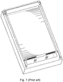
- FIG 1 shows a screening arrangement of the prior art in the form of an awning blind designed for external use, i.e. being mounted outside the building.
- Screening arrangements as the ones described in the background comprise a screening body typically in the form of a roller blind or a roller shutter, which is connected at an upper first end to a rolling tube and at a lower second end to a bottom bar.
- the rolling tube is adapted for being arranged at a first frame member of the window, usually the top frame member, such that the bottom bar can be moved downwards towards a second frame member of the window, usually the bottom frame member, to bring the screening body into the screening position.
- the bottom bar is provided such that the screening body is maintained tensioned. This is of importance when the screening arrangement is installed in an inclined or horizontal roof window, where gravity may make the screening body sack downwards if it is not kept stretched out between the rolling tube and the bottom bar.
- the screening arrangement comprises two guidance cords, each running from the rolling tube towards the second frame member alongside a respective side of the screening body, past a return member at the second frame member and back towards the bottom bar which they are connected to, such that the guidance cords apply a force in the longitudinal direction towards the second frame member on the bottom bar, such that the screening body is kept tensioned between the rolling tube and the bottom bar.
- the guidance cord should apply the force symmetrically in relation to the midpoint of the bottom bar.
- the guidance cord tense To keep the guidance cord tense, they are connected to winding reels arranged on each end of the rolling tube, such that the winding reels are in direct engagement with the rolling tube, i.e. they rotate in unison at the same angular velocity.
- This solution is usually used for screening arrangements adapted for exterior use, as the width added to the screening arrangement by the winding reels make it impossible to fit between two members frame members unless the rolling tube and thus also the screening body is made narrower. Furthermore, the visible winding reels make the screening arrangement less aesthetically appealing to the user.
- the screening arrangements 1 of the invention comprise a winding device 2 which is substantially arranged inside a hollow rolling tube 3. This allows the rolling tube 3 and the screening body 9 to have a width substantially equal to the width of the central opening of the frame of the window in which the screening arrangement 1 is adapted to be installed in. It also makes the winding device 2 less visible and thus more discrete to the user.
- the guidance cords 5a, 5b must keep the screening body 9 tensioned between the rolling tube 3 and the bottom bar 4. This means that the winding reels should unwind/wind a length of guidance cord 5a, 5b substantially equal the length of screening body 9 rolled/unrolled by the rolling tube 3 when the screening body is moved between positions.
- Figs. 2 to 5 show different examples of guidance cord configuration which would work with the screening arrangement 1 of the invention.
- Fig. 3 shows the most primitive solution, wherein a single guidance cord 5 is connected at a first end to the winding device 2 and at the other second end to the center of the bottom bar 5. This solution will keep the screening body 9 stretched out between the rolling tube 3 and the bottom bar 4, while also applying a symmetrical force on the bottom bar 4 so that it is kept parallel with the rolling tube 3.
- this guidance cord configuration is that a single guidance cord 5 can keep the tension on the screening body 9. This means that the screening body 9 can be moved almost free from internal friction caused by the friction between the guidance cord 5 and the various redirection elements used to guide the guidance cord 5.
- the guidance cord configuration shown in Fig. 3 do however suffer from the disadvantage, that the guidance cord 5 is highly visible to the user, as the guidance cord extends across the window pane of the window. Furthermore, as the guidance cord 5 is only connected to the bottom bar 4 at one location, it will be unable to maintain the bottom bar parallel with the rolling tube 3, when the bottom bar 5 is affected by outside forces.
- Fig. 4 shows another embodiment of the invention also using a single guidance cord 5.
- the guidance cord 5 extends from the winding device 2 to a return element, then to one end of the bottom bar 5, through the bottom bar 5, and finally down to the second frame member where it is connected.
- this guidance cord configuration is better at maintaining the bottom bar 4 parallel with the rolling tube 3, while also benefiting from the advantages of having only a single guidance cord 5. It does however require that the winding reel winds/unwinds twice the length of screening body 9 unrolled/rolled from the rolling tube 3. This means that the winding reel must rotate additional times for each movement of the screening body 9,.
- Fig. 5 shows another embodiment of the invention also using a single guidance cord 5.
- the guidance cord 5 splits into two second ends connected to respective sides of the bottom bar 5. Where one of the second ends extends from the second frame member to the bottom bar 4, the other second end extends alongside the second frame member and then towards the other respective side of the bottom bar 5.
- the guidance cord 5 should be composed of an un-split cord portion with a length of at least the distance between the winding device 2 and the return element 6, and two split cord portions, one having a length of at least the distance between the bottom bar in the non-screening position and the return element 6 and one having a length of at least the distance between the bottom bar in the non-screening position and the return element 6 plus the width of the second frame member.
- a preferred guidance cord configuration is shown in figure 2 , wherein two guidance cords 5a, 5b extend alongside respective sides of the screening body 9 and are connected at their first ends to the winding device 2 and at their respective second ends to the bottom bar 4.
- this guidance cord configuration requires two guidance cords 5a, 5b, it provides the most stable guidance of the bottom bar 4 while also being visually discrete to the user, especially if the screening arrangement 1 is provided with side rails 71.
- the spring elements 7a, 7b shown in Fig. 2 are optional and are adapted to compensate for the rolling tube rolling/unrolling a length of screening body 9 different from the length of guidance cord 5a, 5b unwound/wound by the winding reel(s).
- Such spring elements can be arranged inside the bottom bar 4 as shown in Fig. 2 .
- Figs. 2 to 5 show the screening arrangement mounted on the front surface of the frame, the screening arrangement is perferably adapted to be mounted inside the central opening of a window frame.
- a winding device 2 adapted for use with embodiments comprising two guidance cords 5a, 5b, like the one shown in Fig. 2 .
- the winding device 2 comprises two winding reels 21a, 21b, each adapted for storing a respective one of the two guidance cords 5a, 5b. While some embodiments of the invention only comprise a single winding reel 21 adapted to store both of the two guidance cords 5a, 5b, the guidance cords 5a, 5b have a smaller chance of getting entangled if stored on separate winding reels 21a, 21b.
- the winding device 2 has dimensions which are smaller than the inner dimensions of the hollow rolling tube 3.
- the screening arrangement 1 comprises an insertion piece 32.
- the insertion piece comprises two surface portions, a first surface portion adapted to be inserted into the rolling tube 3, said first surface portion having an outer circumference which allows it to fit tightly into the hollow cavity of the rolling tube 3, and a second surface portion which has a diameter substantially equal to the of the rolling tube 3.
- the insertion piece 32 will form part of the rolling tube 3, whereby the total length of the rolling tube 3 will be the length of the central rolling tube itself plus the width of the second surface portion.
- the insertion piece 32 may be provided with a number of flanges 39 adapted to be received in corresponding recesses 31 in the rolling tube 3 to ensure that the central rolling tube 3 and the insertion piece 32 rotate in unison.
- the winding device 2 comprises a winding guide 23.
- the winding guide 23 is adapted for redirecting the guidance cords 5a, 5b, which extend in the transverse direction into the rolling tube 3 from respective ends of the rolling tube 3, onto the respective winding reels 21a, 21b. This is done either by passing the guidance cords 5a, 5b over rounded corners with a low friction surface or by providing a pulley 24 on the winding guide 23.
- the winding guide 23 is mounted on two rails 27 extending from a side piece 28 (shown in Fig.
- the two winding reels 21a, 21b are arranged side-by-side. This allows a single winding guide 23 to be used, as it can simultaneously guide both guidance cords 5a, 5b onto their respective winding reel 5a, 5b.
- the winding reels may be arranged differently, e.g. in opposite ends of the rolling tube 3, whereby a separate winding guide 23 will have to be provided for each winding reel 21a, 21b.
- An advantage of arranging the winding reels 21a, 21b side-by-side such that a single winding guide 23 can guide both guidance cords 5a, 5b onto their respective winding reels 21a, 21b, is that the guidance cords 5a, 5b which extend onto the winding guide 23 from opposite ends of the rolling tube 3 will apply equal oppositely directed forces on the winding guide 23. This allows the winding guide 23 to slide almost frictionless alongside the winding reels, thereby not adding to the friction of the screening arrangement 1 and thus providing a more seamless movement of the screening body 9.
- the winding reels 21a, 21b of the shown embodiment, and winding reels in general, comprise a cord thread on their outer surface, which is adapted to store a respective guidance cord 5a, 5b in a single layer.
- the cord thread enables each winding reel 21a, 21b to store the guidance cord 5a, 5b without risking that the guidance cords 5a, 5b become entangled.
- a further advantage of the cord thread is that the guidance cords 5a, 5b are stored in one layer on the winding reels 21a, 21b. This allows the winding reel 21a, 21b to unwind a predetermined length of guidance cord 5a, 5b for each revolution of the winding reel 21a, 21b.
- the winding reels 21a, 21b are rotatably connected to the side piece 28 (shown in Fig. 11 ) in one end of the winding reels 21a, 21b.
- the winding device 2 of the shown embodiment further comprises an end element 29 attached at the end of the rails 27, to which end element 29 the winding reels 21a, 21b are rotatably connected at their other end.
- the end element 29 could be omitted, it provides stability to the winding device by keeping the winding reels 21a, 21b stable during rotation.
- Fig. 9 and 10 show exploded views of the winding device shown 2 in Fig. 6 .
- the guidance element 22 which guides the guidance cord 5a, 5b from the end opening of the rolling tube 3 towards the winding guide 23 and the winding reels 21a, 21b can be seen.
- the guidance element 22 is provided by a pulley but it may alternatively be provided by a rounded corner with a low friction surface. By adding a guidance element 22 the guidance cords 5a, 5b may pass more frictionless into the rolling tube 3.
- a similar guidance element may be arranged at the opposite end of the rolling tube 3 to guide the guidance cord 5b from the opposite side of the rolling tube 3 towards the respective winding reel 21b.
- the winding reels 21a, 21b comprise a gear each 26a, 26b.
- the gears 26, 26b provide an engagement between each winding reel 21a, 21b to an annular gear 33 (shown in Fig. 8 to 10 ) arranged on an inner side of the insertion piece 32, and thereby also an engagement between each winding reel 21a, 21b and the rolling tube 3.
- the ratio between the number of teeth on the winding reel gears 26a, 26b and on the annular gear 33, is such that the winding reels 21a, 21b rotate more times than the rolling tube 3, thus allowing them to unwind/wind a length of guidance cord 5a, 5b substantially equal to the length of screening body 9 unrolled/rolled by the rolling tube 3.
- Fig. 8 shows an end view of the winding device 2 of figs. 6 and 7 .
- the gears 26a, 26b on the winding reels 21a, 21b comprise 12 teeth each and the annular gear 33 comprises 40.
- the winding reels 21a, 21b will therefore perform 3 1/3 revolutions for each revolution of the rolling tube 3. This allows the winding reels 21a, 21b to have a diameter approximately 3 times smaller than the rolling tube 3, and therefore also allows two winding reels 21a, 21b to be arranged side-by-side inside the hollow cavity of the rolling tube 3.
- the length of screening body 9 unrolled/rolled per rotation of the rolling tube 3 depends on the number of layers of screening body 9 stored on the rolling tube 3 at the given position, as each layer of screening body 9 rolled onto the rolling tube 3 increases the diameter of the rolling tube 3 by approximately two times the thickness of the screening body 9.
- the first revolution of the rolling tube 3 will unroll a longer length of screening body 9 than the following revolutions.
- the winding reels 21a, 21b perform a constant number of revolutions for each revolution of the rolling tube 3 this brings some issues if the winding reels 21a, 21b are to match the length of the guidance cords 5a, 5b with the position of the screening body 9. To compensate for this, the winding reels 21a, 21b are made with a conical shape, such that the length of guidance cord 5a, 5b wound/unwound per revolution changes depending on the diameter of the winding reel 21a, 21b at the given position.
- the guidance cords 5a, 5b will thus be attached to the thickest portion of the winding reels 21a, 21b, such that when the guidance cords 5a, 5b are completely unwound from the winding reels 21a, 21b, i.e. the screening body 9 is completely rolled up on the rolling tube 3, the winding reels 21a, 21b will wind a longer length of guidance cord 5a, 5b in the first revolution than the successive revolutions.
- the winding reels 21a, 21b will therefore wind/unwind substantially the same length of guidance cord 5a, 5b as the length of the screening body 9 unrolled/rolled by the rolling tube 3, regardless of the position of the screening body 9.
- this may be achieved by varying the pitch of the cord thread along the length of the winding reels 21a, 21b. This would also enable the winding reels 21a, 21b to wind/unwind a varying length of guidance cord 5a, 5b depending on the pitch of the cord thread at the given position.
- the screening arrangement 1 may be provided with a spring element 7a, 7b and/or an elastic guidance cord 5a, 5b to help compensate for the varying length of screening body 9 unrolled/rolled for each revolution of the rolling tube 3, such that the guidance cords 5a, 5b can maintain the screening body 9 stretched at all positions depending on the tolerance of the window in which the screening arrangement 1 is to be mounted.
- Fig. 11 shows a cross-sectional view of a screening device 2.
- the winding device 2 is shown with two guidance cords 5a, 5b connected to respective winding reels 21a, 21b of the winding device 2.
- the guidance cords 5a, 5b extend from opposite ends of the rolling tube 3 in the transverse direction between a respective guidance element 22 and the winding guide 24. This configuration allows the two guidance cords 5a, 5b to apply substantially equal oppositely directed forces on the winding guide 24 as described above. This means that the guidance cords 5a, 5b will be guided onto the winding reels 21a, 21b in a direction perpendicular to the transversal direction.
- the winding device comprises a side piece 28 adapted to be attached to a frame member of the window.
- the insertion piece 32 is rotatably connected to the side piece 28.
- the rotatable connection may preferably be provided by a ball bearing or by a smooth cylindrical outer surface of the side piece 28, on which a smooth cylindrical inner surface of the insertion piece 32 may rotate around.
- the winding guide 23 may be in engagement with at least one of the winding reels 21a, 21b, such that rotation of the winding reels 21a, 21b causes movement of the winding guide 23 along the length of the winding reels 21a, 21b.
- Figs. 12 to 14 show and embodiment of the invention, wherein this is accomplished by a pair of engagement protrusions 231 adapted to follow the thread of an adjacent winding reel 21b.
- the engagement protrusions 231 are arranged such, that they occupy unused thread of the winding reel 21b, i.e. the guidance cord 5b is guided onto the thread behind the engagement protrusions 231.
- Fig. 14 shows a winding reel 21 adapted to be in engagement with the engagement protrusions 231 of the winding guide 23. While the winding reel 21 itself is conical as described above, the walls of the thread increase in height, such that the engagement protrusions 231 remain in engagement, even when the depth of the thread increases along the length of the winding reel 21b.
- a conical winding reel 21b is arranged at an angle in relation to the path of the winding guide 23 such that the distance between the winding guide 23 and the conical winding reel 21b remain constant as the winding guide 23 moves along the length of the winding reel 21b.
- the winding guide 24 will only comprise a single engagement protrusion 231 and not two as in the embodiment shown in Fig. 12 .
- a screening arrangement 1 according to the invention is shown without the screening body 9 and the guidance cords 5.
- the screening arrangement 1 may comprise a side piece 28 and an insertion piece 32 connect the other end of the rolling tube 3 to mount the screening arrangement 1 to the opposite frame member of the window.
- the winding device 2 may comprise two side pieces 28 arranged in opposite ends of the rolling tube 3. Each of the two side pieces 28 being connected to an insertion piece 32 and each side piece 28 being rotatably connected to a respective winding reel 21a, 21b.
- the return element 6 comprises a pulley 61 which allows the guidance cord 5 to be guided back towards the bottom bar 5 almost frictionless.
- the pulley may be replaced by a rounded low-friction surface.
- the shown return element 6 is adapted for being mounted on the third or fourth frame member near the second frame member so that the guidance cords 5a, 5b can provide a force in the longitudinal direction towards the second frame member on the bottom bar 4 in any position of the screening body 9.
- the front face of the return element 6 is flat, so that the bottom bar can pass is, so that the return element 6 and the bottom bar 4 are flush with each other in the fully extended screening position of the screening body 9.
- the window arrangement of the invention may comprise a bottom rail arranged at the second frame member to cover the gap between the second frame member and the bottom bar 4 in the fully extended position of the screening body 9.
- the return element 6 has been provided with an aperture 62 for attachment means such as screws.
- the return element 6 may be an integral part of either a side or a bottom rail, such that the number of individual parts may be reduced.
- a winding device 2 according to the invention is shown mounted in a window.
- the winding device 2 is shown without the rolling tube 3 and the screening body 9 to illustrate the placement of the winding device 2 when mounted.
- Fig. 21 shows a screening arrangement 1 according to the invention mounted at a top frame member of a window.
- the screening arrangement 1 comprises side rails 71 arranged at the side frame members of the window, such that they cooperate with the screening body 9 to fully screen the window.
- the screening arrangement 1 of the invention allows the rolling tube 3 and the screening body 9 to be made almost as wide as the length between the two side frame members, the screening body 9 can cover most of the window pane on its own, thus enabling that the side rails be made as slim as possible. This has shown to be valued by the end users, to whom the aesthetic appearance of the screening arrangement 1 is also an important featu re.
- the side rails 71 may comprise guide rails adapted to guide the screening body 9 and/or the bottom bar 5 during movement of these.
- the side rails 71 also allow the guidance cords 5a, 5b to be protected and concealed, as the guidance cords 5a, 5b may be led to the bottom frame member and back up to the bottom bar 4 behind the side rails 71, such that they are less likely to get entangled with the user and are less visible.
- the returns element(s) 6 can be integrated in the side rails, which facilitates installation of the screening arrangement 1.
- the shown screening arrangement 1 further comprises a top rail 72 adapted for covering the gap between the screening body 9 and the first frame member, such that the screening arrangement 1 may provide substantially complete screening of light.
- the screening arrangement 1 further comprises a motor device 8 arranged inside the rolling tube 3 in engagement with the rolling tube 3.
- a motor device 8 arranged inside the rolling tube 3 in engagement with the rolling tube 3.
- the screening arrangement 1 is shown from a perspective view.
- the screening arrangement 1 is shown with only half of the bottom bar 4 and without the right side piece and side rail 72 such that the rolling tube 3 and the motor device 8 can be seen.
- the motor device 8 comprises a motor 80 which is arranged inside the rolling tube 3. This allows the rolling tube 3 and the screening body 9 to be made wider than in screening arrangements, wherein the motor is placed in extension of the rolling tube.
- the motor 80 and the rolling tube 3 are in engagement via an annular gear 35.
- the motor device 8 is connected to an insertion piece 32, which when inserted into the central rolling tube 3 forms part of the rolling tube 3.
- the motor 80 is in engagement with an annular gear 35 attached to the insertion piece 32 via a pinion 86 connected to an axle of the motor 80.
- the motor 80 may be an electrical motor powered by a battery and/or a solar cell of the screening arrangement 1, such that the screening arrangement may function autonomously, or coupled to an external power source, e.g. the power grid, such that the screening arrangement 1 may function without needing replacement of batteries.
- the motor 80 is arranged such that a clearance 81 is provided within the cross-sectional space of the rolling tube 3. In the shown embodiment, this is achieved by using a cylindrical motor 80 with a diameter smaller than the inner diameter of the rolling tube 3, the motor 80 being arranged such that the central axis of the motor 80 is parallel with the central axis of the rolling tube 3, i.e. both extending in the transverse direction. To maximize the dimensions of the clearance in the cross-sectional space, the motor 80 is arranged eccentrically in relation to the rolling tube 3.
- the pinion 86 has a smaller diameter than the inner diameter of the annular gear 35. Providing a pinion 86 with a smaller diameter than then inner diameter of the annular gear 35 is possible, due to the eccentric placement of the motor 80 which brings the axle closer to the annular gear 35. In alternative embodiments, it is enabled by placing an intermediary secondary gear between the pinion 86 and the annular gear 35 to transfer the torque of the pinion 86 to the annular gear 35.
- the motor device 8 further comprises a first shielding element 82 arranged between the pinion 86 and the guidance cord (not shown) passing through the clearance 81 in the cross-sectional space of the rolling tube 3. This ensures that the guidance cord (not shown) can pass the clearance 81 without getting entangled in the pinion 86 or the axle of the motor 80.
- the first shielding element 82 may be provided by a metal or plastic plate attached to the motor 80 or to a side piece 88.
- the plate forming the first shielding element 82 has a curvature matching the curvature of the pinion 86 such that the first shielding element 82 can be arranged as close as possible to the pinion 86, thus maximizing the area of the clearance 81 in the cross-sectional space.
- all embodiments comprising a pinion 86 with a diameter smaller than the inner diameter may comprise such a shielding element 82.
- These embodiments may also further comprise a second shielding element (not shown) arranged between the guidance cord 5 passing through the clearance 81 and a nearest portion of the annular gear 35, such that the second shielding element prevents the guidance cord from coming into contact with the annular gear 35.
- the first and second shielding elements will thus define a portion of the outer periphery of the clearance 81 in the cross-sectional space.
- the motor device 8 comprises a mounting portion 87 adapted the be connected to a side piece 84, similar to that of the winding device 2, or directly to a frame member of the window.
- the mounting portion 87 enables the motor 80 to be mounted to the window, such that the remains fixed when rotating the rolling tube 3.
Landscapes
- Engineering & Computer Science (AREA)
- Structural Engineering (AREA)
- Architecture (AREA)
- Civil Engineering (AREA)
- Storing, Repeated Paying-Out, And Re-Storing Of Elongated Articles (AREA)
Abstract
Description
- The present invention relates to a screening arrangement for screening of a window, said screening arrangement comprising a screening body having an upper first end and a lower second end, said screening body being movable in a longitudinal direction between a non-screening position, in which the screening body is rolled up, and a screening position, in which the screening body is extended, a hollow rolling tube adapted for being rotatable when mounted, said rolling tube extending in a transverse direction perpendicular to the longitudinal direction and being connected to the first end of the screening body, such that the screening body is rolled up around the rolling tube in the non-screening position, a bottom bar extending parallel with the rolling tube, said bottom bar being connected to the second end of the screening body, and at least one guidance cord, each in one end being connected to a winding device, said at least one guidance cord providing a force in the longitudinal direction on the bottom bar such that the screening body is kept tensioned between the rolling tube and the bottom bar, said winding device comprising at least one winding reel for winding the at least one guidance cord when the screening body is moved to the screening position.
- Screening arrangements for windows, particularly those wherein a screening body is rolled up around a rolling tube are usually provided with a bottom bar connected to the screening body, such that the user may apply a force on the bottom bar to move the screening body between two opposing frame members to put the screening body in a screening or a non-screening position.
- To keep the screening body tensioned, such screening arrangements may comprise guidance cords adapted to apply a force on the bottom bar in the longitudinal direction away from the rolling tube, such that the screening body is stretched between the rolling tube and the bottom bar. This is particularly relevant for screening arrangements for inclined or horizontal windows where gravity may make the screening body sack if the screening body is not kept tensioned. To adapt to the position of the bottom bar, the guidance cords have to be wound/unwound on a winding reel in engagement with the rolling tube, such that the guidance cords are wound when the screening body is unwound from the rolling tube and vice versa.
- The applicant's own
WO 2006/074653 A1 shows such a screening arrangement, wherein the guidance cords are wound or unwound on a winding reel as the bottom bar is moved. However, this solution is mainly applied to external screening arrangements, as the winding reels add to the width of the screening arrangement. For screening arrangements adapted to fit between the frame members of a window, this is undesirable as there is a limited amount of space between the frame members. The added width of the winding reels will therefore mean, that the rolling tube and the screening body will have to be shortened if the screening arrangement is to be able to fit between two frame members of a window frame. - The reduced width of the screening body means that the screening arrangement will have to be provided with wider side rails to cover the remaining portion of the window pane if the screening arrangement is to be able to block out light effectively. Such wide side rails have shown largely unpopular with the users, who prefer the side rails to be as slim as possible.
- On this background it is an object of the invention to provide a screening arrangement, wherein the screening body may be made as wide as possible, while still allowing the screening arrangement to fit between two frame members of a window frame.
- According to the invention, this is achieved by a screening arrangement as mentioned in the background, wherein the at least one winding reel is/are arranged mostly, preferably fully, inside the hollow rolling tube.
- When installed, the hollow rolling tube is arranged at a first frame member of the window, preferably the top frame member, and the bottom bar will be movable between the rolling tube, at which position the screening body is rolled up around the rolling tube, and a second frame member of the window opposite the first member, preferably the bottom frame member, at which position the screening body is fully extended and covers the window pane. It should be noted that the screening body can take any intermediate position between its screening and non-screening positions. Windows in general, comprise a stationary frame and typically also a sash frame. Throughout this text the term frame may refer to either of the two.
- The screening body may be roller blinds, awning blinds, roller shutters, or similar and will preferably be adapted to fit the size of the window which the screening arrangement is to be installed in. In its unrolled condition, the screening body will usually have a rectangular form with two major surfaces, one for facing the interior of the building and one for facing the exterior, and as mentioned above, an upper first end and a lower second end which extends in the transverse direction and two sides extending in the longitudinal direction. If the screening body is provided as roller shutters, the bottom bar may take the form of the lower most slat.
- It should be noted, that the terms upper, lower, and bottom which have been used to describe the ends of the screening body and bottom bar are references to the position which these elements will have in the installed condition. Although most screening arrangements will be adapted to be installed at the top frame member such that the screening body is moved vertically towards the bottom frame member when bringing it into the screening position, it is contemplated that the screening arrangement according to the invention could be adapted to be installed at a side frame member such that the screening body is moved horizontally between the non-screening and the screening positions.
- In order to have the at least one guidance cord(s) maintain the screening body stretched between the rolling tube and the bottom bar, the guidance cord(s) have to apply a force on the bottom bar in the longitudinal direction away from the rolling tube. This may be done by having the at least one guidance cord(s) pass a return element. When installed, the return element will be arranged at the second frame member to redirect the guidance cord towards the bottom bar. In embodiments where two guidance cords are provided, the screening arrangement may comprise two return elements, one arranged at each respective end of the second frame member, i.e. at a position corresponding to the bottom bar when the screening body is fully extended.
- By arranging the winding device inside the at least one winding reel inside the hollow rolling tube, the screening arrangement may benefit from the advantages of one or more guidance cord(s) maintaining the bottom bar parallel with the rolling tube and keeping the screening body tensioned between the rolling tube and the bottom bar, while not suffering from the added width the winding reels add to known screening arrangements. This in turn means that the rolling tube and screening body may be made nearly as wide as the central opening of the window frame or sash, such that the screening body can cover as much of the central opening as possible.
- While portions of the winding reel(s) may extend beyond the boundary of the rolling tube, the term arranged mostly, preferably fully, inside the hollow rolling tube should be understood as the majority of the length of the winding reel(s) being arranged inside the hollow cavity of the rolling tube.
- In an embodiment of the invention at least one guidance element is/are arranged at one or both of the open ends of the rolling tube, such that the at least one guidance element allows the guidance cord(s) to be guided, substantially, in the transverse direction into the rolling tube where it connects with the winding reel(s).
- Because the guidance cord(s) has to maintain the screening body tensioned at all positions between the non-screening and screening positions, the winding reel has to wind a length of guidance cord substantially equal to the length of the screening body unrolled from the rolling tube, or in a few embodiments twice the length of the screening body unrolled from the rolling tube. This is made difficult by the restriction that the winding reel(s) will always have a smaller circumference than the rolling tube if it is to be arranged inside the rolling tube.
- In some embodiments, this may be solved by using a winding reel(s) which has as large a circumference as possible while still being able to be arranged and function inside the rolling tube and attaching the guidance cord(s) to a spring element, preferably at the end of the guidance cord(s) opposite the end attached to the winding device, such that the spring element may compensate for the winding reel(s) not being able to wind/unwind a length of guidance cord equal the length of screening body unrolled/rolled by the rolling tube.
- However, in preferred embodiments, the at least one winding reel(s) is/are in engagement with the rolling tube but rotate at a faster angular velocity than that of the rolling tube. This allows winding reels with a smaller circumference than the rolling tube to revolve several times for each revolution made by the rolling tube, whereby the length of guidance cord wound/unwound can match the length of screening body unrolled/rolled from the rolling tube.
- When moving the screening body between the screening and the non-screening positions, the length of screening body rolled up per revolution of the rolling tube depends on the number of layers of screening body already rolled up on the rolling tube at the given position. This results in a need for the winding reel(s) to take up a varying length of guidance cord depending on the position of the screening body.
- This can be solved by a flexible cord or by providing spring means, e.g. in the form of helical springs, at the respective other ends of the guidance cord(s), whereby the winding reels can wind a substantially constant length of guidance cord per revolution, while the spring means or the flexible cord will compensate for the requirement of winding/unwinding a varying length of guidance cord depending on the position of the screening body by keeping the guidance cord(s) tensioned. The screening arrangement may therefore in any embodiment have the at least one guidance cord be spring-loaded at their respective other ends.
- To ensure that the guidance cord(s) maintain the bottom bar parallel with the rolling tube during operation, the guidance cord(s) should apply a substantially symmetrical guidance force on the bottom bar such that the bottom bar does not experience any torque. In the most primitive embodiment, this is achieved by connecting a single guidance cords to the centre of the bottom bar, from where the guidance cord extends in the longitudinal direction towards the second frame member where it is redirected.
- Although this guidance cord configuration would work it is undesirable to have the guidance cord extend across the window pane where it will be visible to the user. To keep the guidance cord(s) concealed, the guidance cord(s) should preferably extend along the third and/or fourth frame members which connect the first and the second frame member where the guidance cords are more discrete.
- In a preferred embodiment of the invention, the screening arrangement comprises two guidance cords, each in one end being connected to the winding device and being connected to the bottom bar at their respective other ends. By providing the screening arrangement with two guidance cords the bottom bar is kept more stable and the tension on the screening body is better maintained.
- In some embodiment with two guidance cords, each of the two guidance cords extends from a respective end of the bottom bar in the longitudinal direction towards a respective return element at the second frame member and back in the longitudinal direction towards a respective guidance element at an end of the rolling tube and from there towards the winding reel(s). By leading the guidance cords alongside the third and fourth frame member when installed, they will be less visible to the user, especially when the screening arrangement is provided with side rails.
- In embodiments of the invention, wherein the screening arrangement comprises two guidance cords, the winding device may comprise one winding reel for winding both guidance cords. The advantage of winding both guidance cords on the same winding reel is that the winding device will require fewer moving elements. This in turn results in a smaller amount of internal friction caused moving parts.
- In other embodiments of the invention, the screening device comprises two winding reels, each being adapted for winding a respective guidance cord. This solution reduces the risk of entangling the guidance cords during winding/unwinding.
- In such embodiments, the two winding reels are preferably arranged side-by-side. By arranging the winding reels side-by-side both winding reels can fit in one end of the hollow cavity of the rolling tube, thus making room for a motor to be arranged in the opposite end of the rolling tube. This solution does however require that the winding reels have a substantially smaller diameter than the rolling tube in order to fit inside the hollow cavity of the rolling tube. This in turn, means that the winding reels have to rotate several times for each rotation made by the rolling tube, in order to wind/unwind a length of guidance cord substantially equal to the length of screening body unrolled/rolled by the rolling tube.
- In alternative embodiments, the two winding reels are arranged in opposite ends of the rolling tube. This makes it easier to assemble the screening arrangement compared to embodiments where both winding reels are arranged in one end, as one of the guidance cords does not have to be lead through the rolling tube.
- In an embodiment of the invention, the winding device further comprises a winding guide arranged adjacent to each of the at least one winding reels, each winding guide being movable in the transverse direction along the length of the respective winding reel, to guide the at least one guidance cords onto the adjacent winding reel. By providing a winding guide the guidance cord(s) may extend between the end of the rolling tube, preferably from the guidance element(s), and the winding guide such that the guidance cord(s) can more easily be wound/unwound from the winding reel(s).
- In embodiments wherein the winding device comprise two winding reels arranged side-by-side, the winding device may comprises one winding guide arranged between the two winding reels, said winding guide being adapted for guiding each of the guidance cords onto a respective winding reel. This allows the screening arrangement to be made using only a single winding guide, thus saving moving parts, reducing friction, and allowing the guidance cord forces to be canceled out by leading the guidance cords onto the winding guide from opposite ends of the rolling tube.
- In some embodiments of the invention, the two guidance cords apply substantially equal oppositely directed forces on the winding guide(s) in the transverse direction. The advantage of this, is that the forces applied on the winding guide(s) during operation by the guidance cords cancel each other out, such that the winding guide can slide freely during winding/unwinding of the guidance cords without being pulled sideways. This allows the winding guide to guide the guidance cords onto the winding reels without adding substantially to the collected friction of the screening arrangement.
- In embodiments comprising one winding guide, this is achieved by passing both guidance cords over the winding guide from opposite transverse directions, i.e. from different ends of the rolling tube, whereby the forces applied on the winding guide by the guidance cords will cancel out.
- In an embodiment of the invention, each winding guide may be provided by a sled slideably arranged alongside the winding surface of the winding reel, whereby at least one guide element of the sled, in the form of a pulley or a rounded corner with a low friction surface, may guide the guidance cord onto the winding reel.
- In an embodiment of the invention, the at least one winding reel(s) is/are in engagement with the rolling tube by means of gears such that the at least one winding reel(s) and the rolling tube rotate in unison, wherein the gear dimensions are such that the at least one winding reels rotate at a higher angular velocity than the rolling tube.
- This solves the aforementioned problem that the winding reel(s) has to unwind/wind a length of guidance cord substantially equal to the length of screening body rolled/unrolled by the rolling tube in order to keep the screening body tensioned between the rolling tube and the bottom bar. The gearing may be provided in several ways, in a preferred embodiment, the winding device comprises an annular gear, i.e. a circular ring with inwards facing teeth, and each winding reel of the at least one winding reels has a gear in engagement with the annular gear, whereby the winding reels will rotate in unison with the rolling tube. The annular gear may be arranged on an inner side of the rolling tube or on the inner side of an insertion piece adapted to be inserted into the rolling tube.
- In an embodiment of the invention, the screening arrangement further comprises a motor arranged at least partially inside the rolling tube, preferably fully inside the rolling tube. By arranging the motor at least partially inside the rolling tube, the screening arrangement becomes much more compact and even more discrete. Furthermore, when arranged inside the rolling tube, the motor may be protected from any external influences that may occur when opening and closing the window.
- While portions of the motor may extend beyond the boundary of the rolling tube, the term arranged mostly, preferably fully, inside the hollow rolling tube should be understood as the majority of the length of the mo-tor being arranged inside the hollow cavity of the rolling tube.
- In an embodiment of the invention the motor is positioned at one end of the rolling tube, while the winding reel(s) are situated in the opposite end. This allows the motor to be fixedly connected to one the frame members such that it may rotate the rolling tube while remaining fixed itself. In such embodiments, wherein the screening arrangement comprise a guidance cord which extends through the rolling tube, the motor may be displaced from the central axis of the rolling tube, i.e. arranged eccentrically, whereby a clearance in the cross-sectional space of the rolling tube is provided, such that the guidance cord can pass by the motor.
- As the screening arrangement of the invention has achieved smaller frictional forces, it allows movement of the screening body to be done using a smaller motor, both in terms of physical size and effect output. This is an advantage as the motor may powered consume less power, thus enabling use of smaller power supplies such as batteries and/or solar cells.
- In an embodiment of the invention, the screening arrangement further comprises side rails adapted for, in an installed condition, covering the gap between the screening body and the frame members, i.e. the third and fourth frame member. The side rails can in cooperation with the screening body provide an almost complete screening of the window, such that almost all visible light is blocked out.
- In an embodiment of the invention, the screening arrangement further comprises guide rails arranged on both sides of the screening body and extending in the longitudinal direction. The guide rails may assist the guidance cords in guiding the screening body and/or bottom bar when moving the screening body between positions. The guide rails may advantageously be formed in the side rails.
- In an embodiment of the invention, the winding reel(s) comprise a thread on for storing and guiding the at least one guidance cords, preferably in one layer. This enables the winding reel to store the guidance cord in an organized fashion, such that the guidance cord does not risk getting entangled. In embodiments where one winding reel is used to store two guidance cords, the winding reel may comprise two cord threads on its surface, such that the guidance cords can be wound in parallel helices around the winding reel.
- In a preferred embodiment of the invention, the winding reel(s) is/are conical. This provides a solution to the aforementioned problem, that the rolling tube rolls/unrolls varying lengths of screening body depending on how many layers of screening body are already stored on the rolling tube, as the winding reel(s) will also be able to unwind/wind varying lengths of guidance cord, even though the ratio of revolutions between the winding reel(s) and the rolling tube remains constant. In other embodiments of the invention, this is solved by providing winding reel(s) that has a varying pitch of the thread along the length of the winding reel(s).
- In embodiments comprising a winding guide, the winding guide may be in engagement with the respective adjacent winding reel, such that rotation of the adjacent winding reel moves the winding guide along the length of the adjacent winding reel. This can be accomplished by the winding guide comprising an engagement protrusion in engagement with a cord thread of the adjacent winding reel.
- The advantage of providing a winding guide in engagement with the adjacent winding reel, is that the guidance cord is better guided onto to winding reel. This is particularly advantageous when the winding reel comprises a thread for storing the guidance cord, as the guidance cord is prevented from skipping between the grooves of the thread.
- In embodiments wherein two winding reels are arranged side-by-side sharing one winding guide, the winding guide may be in engagement with one or both of the winding reels.
- In the following the invention will be described in further detail by means of examples of embodiments with reference to the schematic drawings, in which
-
Fig. 1 shows a front view of a screening arrangement of the invention mounted in the sash of a roof window; -
Fig. 2 shows an embodiment of a screening arrangement of the invention, comprising two guidance cords; -
Fig. 3 shows an embodiment of a screening arrangement of the invention, comprising a single guidance cord; -
Fig. 4 shows an embodiment of a screening arrangement of the invention, comprising a single guidance cord passing through the bottom bar; -
Fig. 5 shows an embodiment of a screening arrangement of the invention, comprising a single guidance cord which splits into two second ends connected to the bottom bar at respective sides; -
Fig. 6 shows a perspective view of a winding device according to the invention; -
Fig. 7 . shows an exploded view of a winding device according to the invention; -
Fig. 8 shows an end view of a winding device according to the invention; -
Fig. 9 . shows a perspective cutaway view of a winding device according to the invention; -
Fig. 10 shows a perspective cutaway view of a winding device according to the invention; -
Fig. 11 shows a front view of a winding device according to the invention, wherein the guidance cords are shown; -
Fig. 12 shows a perspective view of a winding guide of the winding device of the invention; -
Fig. 13 shows an end view of two winding reels with a single winding guide of the winding device of the invention; -
Fig. 14 shows a winding reel of the winding device of the invention; -
Fig. 15 shows a front view of a screening arrangement according to the invention; -
Fig. 16 shows a perspective view of a screening arrangement according to the invention; -
Fig. 17 shows a top view of a return element of the invention; -
Fig. 18 shows a side view of a return element of the invention; -
Fig. 19 shows a front view of a return element of the invention; -
Fig. 20 shows a perspective view of a winding device according to the invention mounted on a window; -
Fig. 21 shows a screening arrangement according to the invention mounted in a window; -
Fig. 22 . shows and perspective view of a motorized screening arrangement of the invention; -
Fig. 23 shows and end view of a motorized screening arrangement of the invention; and -
Fig. 24 shows a motor unit of a motorized screening arrangement of the invention. - In the following, embodiments of the invention will be described in further detail. Each specific variation of the features can be applied to other embodiments of the invention unless specifically stated otherwise.
- Turning first to
figure 1 , which shows a screening arrangement of the prior art in the form of an awning blind designed for external use, i.e. being mounted outside the building. Screening arrangements as the ones described in the background comprise a screening body typically in the form of a roller blind or a roller shutter, which is connected at an upper first end to a rolling tube and at a lower second end to a bottom bar. - The rolling tube is adapted for being arranged at a first frame member of the window, usually the top frame member, such that the bottom bar can be moved downwards towards a second frame member of the window, usually the bottom frame member, to bring the screening body into the screening position. The bottom bar is provided such that the screening body is maintained tensioned. This is of importance when the screening arrangement is installed in an inclined or horizontal roof window, where gravity may make the screening body sack downwards if it is not kept stretched out between the rolling tube and the bottom bar.
- To keep the screening body tensioned and to keep the bottom bar parallel with the rolling tube, the screening arrangement comprises two guidance cords, each running from the rolling tube towards the second frame member alongside a respective side of the screening body, past a return member at the second frame member and back towards the bottom bar which they are connected to, such that the guidance cords apply a force in the longitudinal direction towards the second frame member on the bottom bar, such that the screening body is kept tensioned between the rolling tube and the bottom bar. To keep the bottom bar parallel with the rolling tube the guidance cord should apply the force symmetrically in relation to the midpoint of the bottom bar.
- To keep the guidance cord tense, they are connected to winding reels arranged on each end of the rolling tube, such that the winding reels are in direct engagement with the rolling tube, i.e. they rotate in unison at the same angular velocity.
- This solution is usually used for screening arrangements adapted for exterior use, as the width added to the screening arrangement by the winding reels make it impossible to fit between two members frame members unless the rolling tube and thus also the screening body is made narrower. Furthermore, the visible winding reels make the screening arrangement less aesthetically appealing to the user.
- Turning now to
Figs. 2 to 5 , whereinscreening arrangements 1 according to the invention are shown. The functioning principle of thescreening arrangements 1 are similar to that shown inFig. 1 , in that thescreening arrangements 1 of the invention also maintains thescreening body 9 tensioned by means of at least oneguidance cord 5. To overcome the problems of the screening arrangement ofFig. 1 , thescreening arrangements 1 of the invention comprise a windingdevice 2 which is substantially arranged inside ahollow rolling tube 3. This allows the rollingtube 3 and thescreening body 9 to have a width substantially equal to the width of the central opening of the frame of the window in which thescreening arrangement 1 is adapted to be installed in. It also makes the windingdevice 2 less visible and thus more discrete to the user. - For this type of
screening arrangement 1 to function, theguidance cords screening body 9 tensioned between the rollingtube 3 and thebottom bar 4. This means that the winding reels should unwind/wind a length ofguidance cord screening body 9 rolled/unrolled by the rollingtube 3 when the screening body is moved between positions. - Screening arrangements of the prior art solve this requirement, by having winding reels with a diameter adapted to wind the length of guidance cord per revolution needed to maintain the screening body tensioned. For screening arrangements, wherein the winding reels rotate in unison with the rolling tube, the winding reel will thus usually have substantially the same diameter as the rolling tube. This however, is impossible for
screening arrangements 1 of the invention as the winding reels must fit in the hollow cavity of the rolling tube and therefore must have a smaller diameter than the inner diameter of the rollingtube 3. In preferred embodiments of the invention, this is solved by a windingdevice 2 in engagement with the rollingtube 3, wherein the winding reel(s) rotate at an angular velocity different from that of the rollingtube 3 during movement of thescreening body 9. With this solution, the winding reel(s) can rotate faster than the rollingtube 3, such that it can the winding reel(s) 21 can wind/unwind the right length ofguidance cord screening body 9 stretched at all positions. -
Figs. 2 to 5 show different examples of guidance cord configuration which would work with thescreening arrangement 1 of the invention.Fig. 3 shows the most primitive solution, wherein asingle guidance cord 5 is connected at a first end to the windingdevice 2 and at the other second end to the center of thebottom bar 5. This solution will keep thescreening body 9 stretched out between the rollingtube 3 and thebottom bar 4, while also applying a symmetrical force on thebottom bar 4 so that it is kept parallel with the rollingtube 3. - The advantage of this guidance cord configuration is that a
single guidance cord 5 can keep the tension on thescreening body 9. This means that thescreening body 9 can be moved almost free from internal friction caused by the friction between theguidance cord 5 and the various redirection elements used to guide theguidance cord 5. The guidance cord configuration shown inFig. 3 do however suffer from the disadvantage, that theguidance cord 5 is highly visible to the user, as the guidance cord extends across the window pane of the window. Furthermore, as theguidance cord 5 is only connected to thebottom bar 4 at one location, it will be unable to maintain the bottom bar parallel with the rollingtube 3, when thebottom bar 5 is affected by outside forces. -
Fig. 4 shows another embodiment of the invention also using asingle guidance cord 5. In this embodiment theguidance cord 5 extends from the windingdevice 2 to a return element, then to one end of thebottom bar 5, through thebottom bar 5, and finally down to the second frame member where it is connected. Compared to the embodiment shown inFig. 3 , this guidance cord configuration is better at maintaining thebottom bar 4 parallel with the rollingtube 3, while also benefiting from the advantages of having only asingle guidance cord 5. It does however require that the winding reel winds/unwinds twice the length ofscreening body 9 unrolled/rolled from the rollingtube 3. This means that the winding reel must rotate additional times for each movement of thescreening body 9,. -
Fig. 5 shows another embodiment of the invention also using asingle guidance cord 5. In this embodiment theguidance cord 5 splits into two second ends connected to respective sides of thebottom bar 5. Where one of the second ends extends from the second frame member to thebottom bar 4, the other second end extends alongside the second frame member and then towards the other respective side of thebottom bar 5. To allow theguidance cord 5 to reach thebottom bar 4 in the non-screening position, the guidance cord should be composed of an un-split cord portion with a length of at least the distance between the windingdevice 2 and thereturn element 6, and two split cord portions, one having a length of at least the distance between the bottom bar in the non-screening position and thereturn element 6 and one having a length of at least the distance between the bottom bar in the non-screening position and thereturn element 6 plus the width of the second frame member. - A preferred guidance cord configuration is shown in
figure 2 , wherein twoguidance cords screening body 9 and are connected at their first ends to the windingdevice 2 and at their respective second ends to thebottom bar 4. Although this guidance cord configuration requires twoguidance cords bottom bar 4 while also being visually discrete to the user, especially if thescreening arrangement 1 is provided with side rails 71. - The
spring elements Fig. 2 are optional and are adapted to compensate for the rolling tube rolling/unrolling a length ofscreening body 9 different from the length ofguidance cord bottom bar 4 as shown inFig. 2 . - It should be noted, that although
Figs. 2 to 5 show the screening arrangement mounted on the front surface of the frame, the screening arrangement is perferably adapted to be mounted inside the central opening of a window frame. - Turning now to
Fig. 6 , a windingdevice 2 according to the invention is shown adapted for use with embodiments comprising twoguidance cords Fig. 2 . The windingdevice 2 comprises two windingreels guidance cords reel 21 adapted to store both of the twoguidance cords guidance cords reels device 2 to fit inside the rollingtube 3, the windingdevice 2 has dimensions which are smaller than the inner dimensions of thehollow rolling tube 3. - To connect the winding
device 2 to the rollingtube 3, thescreening arrangement 1 comprises aninsertion piece 32. The insertion piece comprises two surface portions, a first surface portion adapted to be inserted into the rollingtube 3, said first surface portion having an outer circumference which allows it to fit tightly into the hollow cavity of the rollingtube 3, and a second surface portion which has a diameter substantially equal to the of the rollingtube 3. Thus, when inserted into the rollingtube 3, theinsertion piece 32 will form part of the rollingtube 3, whereby the total length of the rollingtube 3 will be the length of the central rolling tube itself plus the width of the second surface portion. Theinsertion piece 32 may be provided with a number offlanges 39 adapted to be received in correspondingrecesses 31 in the rollingtube 3 to ensure that thecentral rolling tube 3 and theinsertion piece 32 rotate in unison. - To facilitate winding and unwinding of the
guidance cords device 2 comprises a windingguide 23. The windingguide 23 is adapted for redirecting theguidance cords tube 3 from respective ends of the rollingtube 3, onto the respective windingreels guidance cords pulley 24 on the windingguide 23. To allow the windingguide 23 to slide during winding/unwinding of theguidance cords guide 23 is mounted on tworails 27 extending from a side piece 28 (shown inFig. 11 ) parallel with the windingreels guide 23 to slide alongside the windingreels guidance cord reels - In the shown embodiment the two winding
reels guide 23 to be used, as it can simultaneously guide bothguidance cords reel tube 3, whereby a separate windingguide 23 will have to be provided for each windingreel - An advantage of arranging the winding
reels guide 23 can guide bothguidance cords reels guidance cords guide 23 from opposite ends of the rollingtube 3 will apply equal oppositely directed forces on the windingguide 23. This allows the windingguide 23 to slide almost frictionless alongside the winding reels, thereby not adding to the friction of thescreening arrangement 1 and thus providing a more seamless movement of thescreening body 9. - The winding
reels respective guidance cord reel guidance cord guidance cords guidance cords reels reel guidance cord reel - To allow the winding
reels reels Fig. 11 ) in one end of the windingreels device 2 of the shown embodiment further comprises anend element 29 attached at the end of therails 27, to whichend element 29 the windingreels end element 29 could be omitted, it provides stability to the winding device by keeping the windingreels -
Fig. 9 and 10 show exploded views of the winding device shown 2 inFig. 6 . In these figures, theguidance element 22 which guides theguidance cord tube 3 towards the windingguide 23 and the windingreels guidance element 22 is provided by a pulley but it may alternatively be provided by a rounded corner with a low friction surface. By adding aguidance element 22 theguidance cords tube 3. Although it is not shown in the figure, a similar guidance element may be arranged at the opposite end of the rollingtube 3 to guide theguidance cord 5b from the opposite side of the rollingtube 3 towards the respective windingreel 21b. - In the exploded view it can be seen, that the winding
reels gears reel Fig. 8 to 10 ) arranged on an inner side of theinsertion piece 32, and thereby also an engagement between each windingreel tube 3. The gear dimensions, i.e. the ratio between the number of teeth on the windingreel gears annular gear 33, is such that the windingreels tube 3, thus allowing them to unwind/wind a length ofguidance cord screening body 9 unrolled/rolled by the rollingtube 3. - The gear dimensions can be seen in
Fig. 8 which shows an end view of the windingdevice 2 offigs. 6 and 7 . In the shown embodiment, thegears reels annular gear 33 comprises 40. The windingreels tube 3. This allows the windingreels tube 3, and therefore also allows two windingreels tube 3. - During operation, the length of
screening body 9 unrolled/rolled per rotation of the rollingtube 3 depends on the number of layers ofscreening body 9 stored on the rollingtube 3 at the given position, as each layer ofscreening body 9 rolled onto the rollingtube 3 increases the diameter of the rollingtube 3 by approximately two times the thickness of thescreening body 9. Thus, when thescreening body 9 is in the non-screening position, i.e. all of thescreening body 9 is stored on the rollingtube 3, the first revolution of the rollingtube 3 will unroll a longer length ofscreening body 9 than the following revolutions. - As the winding
reels tube 3 this brings some issues if the windingreels guidance cords screening body 9. To compensate for this, the windingreels guidance cord reel - The
guidance cords reels guidance cords reels screening body 9 is completely rolled up on the rollingtube 3, the windingreels guidance cord reels guidance cord screening body 9 unrolled/rolled by the rollingtube 3, regardless of the position of thescreening body 9. - In other embodiments of the invention, this may be achieved by varying the pitch of the cord thread along the length of the winding
reels reels guidance cord screening arrangement 1 may be provided with aspring element elastic guidance cord screening body 9 unrolled/rolled for each revolution of the rollingtube 3, such that theguidance cords screening body 9 stretched at all positions depending on the tolerance of the window in which thescreening arrangement 1 is to be mounted. -
Fig. 11 shows a cross-sectional view of ascreening device 2. The windingdevice 2 is shown with twoguidance cords reels device 2. Theguidance cords tube 3 in the transverse direction between arespective guidance element 22 and the windingguide 24. This configuration allows the twoguidance cords guide 24 as described above. This means that theguidance cords reels guidance cords guide 23 facilitates storage of theguidance cord reels screening arrangement 1. - To mount the
screening arrangement 1 on the window, the winding device comprises aside piece 28 adapted to be attached to a frame member of the window. To connect the rollingtube 3 to theside piece 28, theinsertion piece 32 is rotatably connected to theside piece 28. The rotatable connection may preferably be provided by a ball bearing or by a smooth cylindrical outer surface of theside piece 28, on which a smooth cylindrical inner surface of theinsertion piece 32 may rotate around. - In embodiments of the invention, wherein the winding
device 1 comprises two windingreels guide 23 may be in engagement with at least one of the windingreels reels guide 23 along the length of the windingreels Figs. 12 to 14 show and embodiment of the invention, wherein this is accomplished by a pair ofengagement protrusions 231 adapted to follow the thread of an adjacent windingreel 21b. The engagement protrusions 231 are arranged such, that they occupy unused thread of the windingreel 21b, i.e. theguidance cord 5b is guided onto the thread behind theengagement protrusions 231. - In
Fig. 13 it can be seen, how theengagement protrusions 231 are in engagement with the thread of one of the adjacent windingreels 21b. as the threads of the two windingreels guide 23 need only be in engagement with one of the windingreels -
Fig. 14 shows a windingreel 21 adapted to be in engagement with theengagement protrusions 231 of the windingguide 23. While the windingreel 21 itself is conical as described above, the walls of the thread increase in height, such that theengagement protrusions 231 remain in engagement, even when the depth of the thread increases along the length of the windingreel 21b. In an alternative embodiment, aconical winding reel 21b is arranged at an angle in relation to the path of the windingguide 23 such that the distance between the windingguide 23 and the conical windingreel 21b remain constant as the windingguide 23 moves along the length of the windingreel 21b. - It should be noted, that in embodiments wherein the thread of the winding
reel 21 is provided with a varying pitch, the windingguide 24 will only comprise asingle engagement protrusion 231 and not two as in the embodiment shown inFig. 12 . - Turning now to
Figs. 15 and 16 , ascreening arrangement 1 according to the invention is shown without thescreening body 9 and theguidance cords 5. In embodiments where the windingdevice 2 is situated in one end of the rollingtube 3, i.e. windingdevices 2 which only comprise a single windingreel 21 or two windingreels screening arrangement 1 may comprise aside piece 28 and aninsertion piece 32 connect the other end of the rollingtube 3 to mount thescreening arrangement 1 to the opposite frame member of the window. - In embodiments where the winding
device 2 comprises two windingreels tube 3, the windingdevice 2 may comprise twoside pieces 28 arranged in opposite ends of the rollingtube 3. Each of the twoside pieces 28 being connected to aninsertion piece 32 and eachside piece 28 being rotatably connected to a respective windingreel - Turning now to
figs. 17, 18, and 19 , an embodiment of thereturn element 6 is shown from the top, side, and front, respectively. Thereturn element 6 comprises apulley 61 which allows theguidance cord 5 to be guided back towards thebottom bar 5 almost frictionless. Alternatively, the pulley may be replaced by a rounded low-friction surface. - The shown
return element 6 is adapted for being mounted on the third or fourth frame member near the second frame member so that theguidance cords bottom bar 4 in any position of thescreening body 9. The front face of thereturn element 6 is flat, so that the bottom bar can pass is, so that thereturn element 6 and thebottom bar 4 are flush with each other in the fully extended screening position of thescreening body 9. In general, the window arrangement of the invention may comprise a bottom rail arranged at the second frame member to cover the gap between the second frame member and thebottom bar 4 in the fully extended position of thescreening body 9. - To mount the
return element 6 on the third or fourth frame member, thereturn element 6 has been provided with anaperture 62 for attachment means such as screws. In other embodiments, thereturn element 6 may be an integral part of either a side or a bottom rail, such that the number of individual parts may be reduced. - Turning now to
Fig. 20 , a windingdevice 2 according to the invention is shown mounted in a window. The windingdevice 2 is shown without the rollingtube 3 and thescreening body 9 to illustrate the placement of the windingdevice 2 when mounted. -
Fig. 21 shows ascreening arrangement 1 according to the invention mounted at a top frame member of a window. Thescreening arrangement 1 comprises side rails 71 arranged at the side frame members of the window, such that they cooperate with thescreening body 9 to fully screen the window. As thescreening arrangement 1 of the invention allows the rollingtube 3 and thescreening body 9 to be made almost as wide as the length between the two side frame members, thescreening body 9 can cover most of the window pane on its own, thus enabling that the side rails be made as slim as possible. This has shown to be valued by the end users, to whom the aesthetic appearance of thescreening arrangement 1 is also an important featu re. - To provide stability to the
bottom bar 5 and thescreening body 9, the side rails 71 may comprise guide rails adapted to guide thescreening body 9 and/or thebottom bar 5 during movement of these. - The side rails 71 also allow the
guidance cords guidance cords bottom bar 4 behind the side rails 71, such that they are less likely to get entangled with the user and are less visible. In some embodiment, the returns element(s) 6 can be integrated in the side rails, which facilitates installation of thescreening arrangement 1. The shownscreening arrangement 1 further comprises atop rail 72 adapted for covering the gap between thescreening body 9 and the first frame member, such that thescreening arrangement 1 may provide substantially complete screening of light. - Turning now to
Figs. 22 to 24 which show amotorized screening arrangements 1 of the invention. To automate movement of thescreening body 9, thescreening arrangement 1 further comprises amotor device 8 arranged inside the rollingtube 3 in engagement with the rollingtube 3. This makes thescreening arrangement 1 well suited for roof windows mounted in tall ceilings and/or allows thescreening arrangement 1 to be coupled to and controlled over a network via an external or internal network connector, preferably a wireless network connector. - In
Fig. 22 thescreening arrangement 1 is shown from a perspective view. In order to better illustrate thescreening arrangement 1, thescreening arrangement 1 is shown with only half of thebottom bar 4 and without the right side piece andside rail 72 such that the rollingtube 3 and themotor device 8 can be seen. As can be seen in the figure, themotor device 8 comprises amotor 80 which is arranged inside the rollingtube 3. This allows the rollingtube 3 and thescreening body 9 to be made wider than in screening arrangements, wherein the motor is placed in extension of the rolling tube. To enable themotor 80 to rotate the rollingtube 3, themotor 80 and the rollingtube 3 are in engagement via anannular gear 35. Like the windingdevice 2, themotor device 8 is connected to aninsertion piece 32, which when inserted into thecentral rolling tube 3 forms part of the rollingtube 3. To allow themotor device 8 to rotate the rollingtube 3, themotor 80 is in engagement with anannular gear 35 attached to theinsertion piece 32 via apinion 86 connected to an axle of themotor 80. - In general, the
motor 80 may be an electrical motor powered by a battery and/or a solar cell of thescreening arrangement 1, such that the screening arrangement may function autonomously, or coupled to an external power source, e.g. the power grid, such that thescreening arrangement 1 may function without needing replacement of batteries. - To allow one or both of the
guidance cord motor 80 inside the rollingtube 3, themotor 80 is arranged such that aclearance 81 is provided within the cross-sectional space of the rollingtube 3. In the shown embodiment, this is achieved by using acylindrical motor 80 with a diameter smaller than the inner diameter of the rollingtube 3, themotor 80 being arranged such that the central axis of themotor 80 is parallel with the central axis of the rollingtube 3, i.e. both extending in the transverse direction. To maximize the dimensions of the clearance in the cross-sectional space, themotor 80 is arranged eccentrically in relation to the rollingtube 3. - To avoid that the
pinion 86 covers the clearance in the cross-sectional space, thepinion 86 has a smaller diameter than the inner diameter of theannular gear 35. Providing apinion 86 with a smaller diameter than then inner diameter of theannular gear 35 is possible, due to the eccentric placement of themotor 80 which brings the axle closer to theannular gear 35. In alternative embodiments, it is enabled by placing an intermediary secondary gear between thepinion 86 and theannular gear 35 to transfer the torque of thepinion 86 to theannular gear 35. - Turning now to
Fig. 23 , an end view of the rollingtube 3 is shown. Themotor device 8 further comprises afirst shielding element 82 arranged between thepinion 86 and the guidance cord (not shown) passing through theclearance 81 in the cross-sectional space of the rollingtube 3. This ensures that the guidance cord (not shown) can pass theclearance 81 without getting entangled in thepinion 86 or the axle of themotor 80. Thefirst shielding element 82 may be provided by a metal or plastic plate attached to themotor 80 or to a side piece 88. In most embodiments the plate forming thefirst shielding element 82 has a curvature matching the curvature of thepinion 86 such that thefirst shielding element 82 can be arranged as close as possible to thepinion 86, thus maximizing the area of theclearance 81 in the cross-sectional space. - In general, all embodiments comprising a
pinion 86 with a diameter smaller than the inner diameter may comprise such ashielding element 82. These embodiments may also further comprise a second shielding element (not shown) arranged between theguidance cord 5 passing through theclearance 81 and a nearest portion of theannular gear 35, such that the second shielding element prevents the guidance cord from coming into contact with theannular gear 35. The first and second shielding elements will thus define a portion of the outer periphery of theclearance 81 in the cross-sectional space. - To mount the
motor device 8, themotor device 8 comprises a mountingportion 87 adapted the be connected to a side piece 84, similar to that of the windingdevice 2, or directly to a frame member of the window. The mountingportion 87 enables themotor 80 to be mounted to the window, such that the remains fixed when rotating the rollingtube 3. - The invention should not be regarded as being limited to the described embodiments. Several modifications and combinations of the different embodiments will be apparent to the person skilled in the art.
-
- 1
- screening arrangement
- 2
- winding device
- 3
- rolling tube
- 4
- bottom bar
- 5a
- guidance cord
- 5b
- guidance cord
- 6a
- return element
- 6b
- return element
- 7a
- spring element
- 7b
- spring element
- 8
- motor device
- 9
- screening body
- 21a
- winding reel
- 21b
- winding reel
- 22
- guidance element
- 24
- winding guide
- 26a
- gear
- 26b
- gear
- 27
- rails
- 28
- side piece
- 29
- end element
- 31
- recesses
- 32
- insertion piece
- 33
- annular gear
- 35
- annular gear
- 37
- biasing element
- 39
- flanges
- 61
- pulley
- 62
- aperture
- 71
- side rails
- 72
- top rail
- 80
- motor
- 81
- clearance
- 82
- guidance element
- 83
- shielding element
- 86
- pinion
- 87
- mounting element
- 88
- side piece
- 231
- engagement protrusions
Claims (15)
- A screening arrangement (1) for screening of a window, said screening arrangement (1) comprising:a screening body (9) having an upper first end and a lower second end, said screening body (9) being movable in a longitudinal direction between a non-screening position, in which the screening body (9) is rolled up, and a screening position, in which the screening body (9) is extended;a hollow rolling tube (3) adapted for being rotatable when mounted, said rolling tube (3) extending in a transverse direction perpendicular to the longitudinal direction and being connected to the first end of the screening body (9), such that the screening body (3) is rolled up around the rolling tube (3) in the non-screening position;a bottom bar (4) extending parallel with the rolling tube (3), said bottom bar (4) being connected to the second end of the screening body (9); andat least one guidance cord (5a, 5b), each in one end being connected to a winding device (2), said at least one guidance cord (5a, 5b) providing a force in the longitudinal direction on the bottom bar (4) such that the screening body (9) is kept tensioned between the rolling tube (3) and the bottom bar (4),characterized in that said winding device (2) comprising at least one winding reel (21a, 21b) for winding the at least one guidance cord (5a, 5b) when the screening body (9) is moved to the screening position, wherein at least one winding reel (21a, 21b) is arranged mostly, preferably fully, inside the hollow rolling tube (3).
- A screening arrangement (1) according to claim 1, wherein the at least one winding reel (21a, 21b) is in engagement with the rolling tube (3) but rotate at an angular velocity different from that of the rolling tube (3) during movement of the screening body (9).
- A screening arrangement (1) according to any one of the preceding claims, wherein the screening arrangement (1) comprises two guidance cords (21a, 21b), each in one end being connected to the winding device (2) and being connected to the bottom bar (4) at their respective other ends.
- A screening arrangement (1) according claim 3, wherein the winding device (2) comprises two winding reels (21a, 21b), each being adapted for winding a respective guidance cord (5a, 5b).
- A screening arrangement (1) according to claim 4, wherein the two winding reels (21a, 21b) are arranged side-by-side.
- A screening arrangement (1) according to claim 3, wherein the winding device (2) comprises one winding reel for winding both of the guidance cords (5a, 5b).
- A screening arrangement (1) according to any one of the preceding claims, wherein the winding device (2) further comprises a winding guide (24) arranged adjacent to each of the at least one winding reels (21a, 21b), each winding guide (24) being movable in the transverse direction along the length of the respective winding reel (21a, 21b), to guide the at least one guidance cords (5a, 5b) onto the adjacent winding reel (21a, 21b).
- A screening arrangement (1) according claims 5 and 7, wherein the winding device (2) comprises one winding guide (24) arranged between the two winding reels (21a, 21b), said winding guide (24) being adapted for guiding each of the guidance cords (5a, 5b) onto a respective winding reel (21a, 21b).
- A screening arrangement (1) according to claim 3 and claim 7 or 8, wherein the two guidance cords (5a, 5b) apply substantially equal oppositely directed forces on the winding guide(s) (24) in the transverse direction.
- A screening arrangement (1) according to any one of the preceding claims, wherein the at least one winding reel(s) (21a, 21b) is/are in engagement with the rolling tube (3) by means of gears (26a, 26b) such that the at least one winding reel(s) (21a, 21b) and the rolling tube (3) rotate in unison, wherein the gear (26a, 26b) dimensions are such that the at least one winding reels (21a, 21b) rotate at a higher angular velocity than the rolling tube (3).
- A screening arrangement (1) according to claim 10, wherein the rolling tube (3) comprises an annular gear (33) in engagement with a gear (26a, 26b) on each of the at least one winding reels (21a, 21b).
- A screening arrangement (1) according to any one of the preceding claims, further comprising a motor device (8) comprising a motor (80), said motor (80) preferably being arranged at least partially inside the rolling tube (3).
- A screening arrangement (1) according to claim 12, wherein the at least one winding reel(s) (21a, 21b) is/are arranged at one end of the rolling tube (3) and the motor device (8) is arranged at the opposite end.
- A screening arrangement (1) according to any one of the preceding claims, wherein the winding reel(s) (21a, 21b) comprise a thread with a varying pitch along the length of the winding reel(s) (21a, 21b), and/or wherein the winding reel(s) (21a, 21b) is/are conical.
- A screening arrangement (1) according to any one of the preceding claims when dependent on claim 7, wherein the winding guide (24) is in engagement with the respective adjacent winding reel (21a, 21b), such that rotation of the adjacent winding reel (21a, 21b) moves the winding guide (24) along the length of the adjacent winding reel (21a, 21b).
Priority Applications (1)
| Application Number | Priority Date | Filing Date | Title |
|---|---|---|---|
| PL18176861T PL3412861T3 (en) | 2017-06-09 | 2018-06-08 | Screening arrangement with internal winding device |
Applications Claiming Priority (1)
| Application Number | Priority Date | Filing Date | Title |
|---|---|---|---|
| DKPA201770452 | 2017-06-09 |
Publications (2)
| Publication Number | Publication Date |
|---|---|
| EP3412861A1 true EP3412861A1 (en) | 2018-12-12 |
| EP3412861B1 EP3412861B1 (en) | 2020-11-04 |
Family
ID=62597394
Family Applications (1)
| Application Number | Title | Priority Date | Filing Date |
|---|---|---|---|
| EP18176861.5A Active EP3412861B1 (en) | 2017-06-09 | 2018-06-08 | Screening arrangement with internal winding device |
Country Status (2)
| Country | Link |
|---|---|
| EP (1) | EP3412861B1 (en) |
| PL (1) | PL3412861T3 (en) |
Citations (3)
| Publication number | Priority date | Publication date | Assignee | Title |
|---|---|---|---|---|
| DE2409320A1 (en) * | 1973-02-28 | 1974-08-29 | Sigfried Lidin | ROLLING DEVICE FOR A FLEXIBLE SHEET |
| CA1157766A (en) * | 1981-09-24 | 1983-11-29 | Walter Timoschuk | Wire drum for door |
| WO2006074653A1 (en) * | 2005-01-11 | 2006-07-20 | Vkr Holding A/S | A winding device for a cord guidance system of a screening device for the screening of a window |
-
2018
- 2018-06-08 PL PL18176861T patent/PL3412861T3/en unknown
- 2018-06-08 EP EP18176861.5A patent/EP3412861B1/en active Active
Patent Citations (3)
| Publication number | Priority date | Publication date | Assignee | Title |
|---|---|---|---|---|
| DE2409320A1 (en) * | 1973-02-28 | 1974-08-29 | Sigfried Lidin | ROLLING DEVICE FOR A FLEXIBLE SHEET |
| CA1157766A (en) * | 1981-09-24 | 1983-11-29 | Walter Timoschuk | Wire drum for door |
| WO2006074653A1 (en) * | 2005-01-11 | 2006-07-20 | Vkr Holding A/S | A winding device for a cord guidance system of a screening device for the screening of a window |
Also Published As
| Publication number | Publication date |
|---|---|
| PL3412861T3 (en) | 2021-05-04 |
| EP3412861B1 (en) | 2020-11-04 |
Similar Documents
| Publication | Publication Date | Title |
|---|---|---|
| US6257305B1 (en) | Method and apparatus for driving and storing a covering | |
| US10294718B2 (en) | Pull across roll up screen assembly | |
| AU2005287216B2 (en) | Anti-bow roller tube arrangement | |
| EP3175073B1 (en) | A retrofitable retractable screen system | |
| US20130269885A1 (en) | Motorized Operating Device Intended for Operating a Movable Screen with a Windable Canvas of a Window Covering Device or a Projection Screen Device | |
| GB2437962A (en) | Cordless blind mechanism | |
| WO2009139751A1 (en) | Spring biased slide arrangement for anti-bow roller tube | |
| US20080202705A1 (en) | Cordless Blinds with Secondary Blind Adjustment Means | |
| WO2017007944A1 (en) | Cable drum drive system for sliding window sash | |
| US6935398B2 (en) | Operating unit for a window covering | |
| US11473369B2 (en) | Top-down bottom-up window covering | |
| EP3412861B1 (en) | Screening arrangement with internal winding device | |
| GB2535506A (en) | Retractable blind system | |
| EP3412860B1 (en) | Screening arrangement with internal motor | |
| CN102182391A (en) | Hollow glass with built-in sunblind and hollow glass system | |
| US20210017809A1 (en) | Rolling shutter system and component parts | |
| EP2094931B1 (en) | Screening device | |
| CN202055728U (en) | Manual drive mechanism and manual hollow glass system | |
| CN223034882U (en) | Built-in roller shutter drive device, built-in roller shutter mechanism and built-in roller shutter glass product | |
| US20050139331A1 (en) | Overhead door apparatus with enclosed counterbalance mechanism | |
| AU776515B2 (en) | A method and apparatus for driving and storing a covering | |
| CN212027615U (en) | Single motor drive formula roller shutter | |
| CN201981983U (en) | Built-in sun-shading curtain insulating glass and insulating glass system | |
| KR200222378Y1 (en) | Adjuster of blind | |
| JP7094518B2 (en) | Automatic closing device for sliding doors |
Legal Events
| Date | Code | Title | Description |
|---|---|---|---|
| PUAI | Public reference made under article 153(3) epc to a published international application that has entered the european phase |
Free format text: ORIGINAL CODE: 0009012 |
|
| STAA | Information on the status of an ep patent application or granted ep patent |
Free format text: STATUS: THE APPLICATION HAS BEEN PUBLISHED |
|
| AK | Designated contracting states |
Kind code of ref document: A1 Designated state(s): AL AT BE BG CH CY CZ DE DK EE ES FI FR GB GR HR HU IE IS IT LI LT LU LV MC MK MT NL NO PL PT RO RS SE SI SK SM TR |
|
| AX | Request for extension of the european patent |
Extension state: BA ME |
|
| STAA | Information on the status of an ep patent application or granted ep patent |
Free format text: STATUS: REQUEST FOR EXAMINATION WAS MADE |
|
| 17P | Request for examination filed |
Effective date: 20190606 |
|
| RBV | Designated contracting states (corrected) |
Designated state(s): AL AT BE BG CH CY CZ DE DK EE ES FI FR GB GR HR HU IE IS IT LI LT LU LV MC MK MT NL NO PL PT RO RS SE SI SK SM TR |
|
| RIC1 | Information provided on ipc code assigned before grant |
Ipc: E06B 9/42 20060101AFI20190822BHEP Ipc: E06B 9/72 20060101ALI20190822BHEP Ipc: E06B 9/58 20060101ALI20190822BHEP Ipc: E06B 9/44 20060101ALI20190822BHEP |
|
| GRAP | Despatch of communication of intention to grant a patent |
Free format text: ORIGINAL CODE: EPIDOSNIGR1 |
|
| STAA | Information on the status of an ep patent application or granted ep patent |
Free format text: STATUS: GRANT OF PATENT IS INTENDED |
|
| INTG | Intention to grant announced |
Effective date: 20191016 |
|
| GRAJ | Information related to disapproval of communication of intention to grant by the applicant or resumption of examination proceedings by the epo deleted |
Free format text: ORIGINAL CODE: EPIDOSDIGR1 |
|
| STAA | Information on the status of an ep patent application or granted ep patent |
Free format text: STATUS: REQUEST FOR EXAMINATION WAS MADE |
|
| GRAP | Despatch of communication of intention to grant a patent |
Free format text: ORIGINAL CODE: EPIDOSNIGR1 |
|
| STAA | Information on the status of an ep patent application or granted ep patent |
Free format text: STATUS: GRANT OF PATENT IS INTENDED |
|
| INTC | Intention to grant announced (deleted) | ||
| INTG | Intention to grant announced |
Effective date: 20200309 |
|
| GRAJ | Information related to disapproval of communication of intention to grant by the applicant or resumption of examination proceedings by the epo deleted |
Free format text: ORIGINAL CODE: EPIDOSDIGR1 |
|
| STAA | Information on the status of an ep patent application or granted ep patent |
Free format text: STATUS: REQUEST FOR EXAMINATION WAS MADE |
|
| INTC | Intention to grant announced (deleted) | ||
| GRAS | Grant fee paid |
Free format text: ORIGINAL CODE: EPIDOSNIGR3 |
|
| STAA | Information on the status of an ep patent application or granted ep patent |
Free format text: STATUS: GRANT OF PATENT IS INTENDED |
|
| GRAP | Despatch of communication of intention to grant a patent |
Free format text: ORIGINAL CODE: EPIDOSNIGR1 |
|
| GRAA | (expected) grant |
Free format text: ORIGINAL CODE: 0009210 |
|
| STAA | Information on the status of an ep patent application or granted ep patent |
Free format text: STATUS: THE PATENT HAS BEEN GRANTED |
|
| INTG | Intention to grant announced |
Effective date: 20200915 |
|
| AK | Designated contracting states |
Kind code of ref document: B1 Designated state(s): AL AT BE BG CH CY CZ DE DK EE ES FI FR GB GR HR HU IE IS IT LI LT LU LV MC MK MT NL NO PL PT RO RS SE SI SK SM TR |
|
| REG | Reference to a national code |
Ref country code: GB Ref legal event code: FG4D |
|
| REG | Reference to a national code |
Ref country code: CH Ref legal event code: EP |
|
| REG | Reference to a national code |
Ref country code: AT Ref legal event code: REF Ref document number: 1331029 Country of ref document: AT Kind code of ref document: T Effective date: 20201115 |
|
| REG | Reference to a national code |
Ref country code: IE Ref legal event code: FG4D |
|
| REG | Reference to a national code |
Ref country code: DE Ref legal event code: R096 Ref document number: 602018009318 Country of ref document: DE |
|
| REG | Reference to a national code |
Ref country code: NL Ref legal event code: FP |
|
| REG | Reference to a national code |
Ref country code: AT Ref legal event code: MK05 Ref document number: 1331029 Country of ref document: AT Kind code of ref document: T Effective date: 20201104 |
|
| PG25 | Lapsed in a contracting state [announced via postgrant information from national office to epo] |
Ref country code: PT Free format text: LAPSE BECAUSE OF FAILURE TO SUBMIT A TRANSLATION OF THE DESCRIPTION OR TO PAY THE FEE WITHIN THE PRESCRIBED TIME-LIMIT Effective date: 20210304 Ref country code: RS Free format text: LAPSE BECAUSE OF FAILURE TO SUBMIT A TRANSLATION OF THE DESCRIPTION OR TO PAY THE FEE WITHIN THE PRESCRIBED TIME-LIMIT Effective date: 20201104 Ref country code: FI Free format text: LAPSE BECAUSE OF FAILURE TO SUBMIT A TRANSLATION OF THE DESCRIPTION OR TO PAY THE FEE WITHIN THE PRESCRIBED TIME-LIMIT Effective date: 20201104 Ref country code: GR Free format text: LAPSE BECAUSE OF FAILURE TO SUBMIT A TRANSLATION OF THE DESCRIPTION OR TO PAY THE FEE WITHIN THE PRESCRIBED TIME-LIMIT Effective date: 20210205 Ref country code: NO Free format text: LAPSE BECAUSE OF FAILURE TO SUBMIT A TRANSLATION OF THE DESCRIPTION OR TO PAY THE FEE WITHIN THE PRESCRIBED TIME-LIMIT Effective date: 20210204 |
|
| PG25 | Lapsed in a contracting state [announced via postgrant information from national office to epo] |
Ref country code: SE Free format text: LAPSE BECAUSE OF FAILURE TO SUBMIT A TRANSLATION OF THE DESCRIPTION OR TO PAY THE FEE WITHIN THE PRESCRIBED TIME-LIMIT Effective date: 20201104 Ref country code: IS Free format text: LAPSE BECAUSE OF FAILURE TO SUBMIT A TRANSLATION OF THE DESCRIPTION OR TO PAY THE FEE WITHIN THE PRESCRIBED TIME-LIMIT Effective date: 20210304 Ref country code: LV Free format text: LAPSE BECAUSE OF FAILURE TO SUBMIT A TRANSLATION OF THE DESCRIPTION OR TO PAY THE FEE WITHIN THE PRESCRIBED TIME-LIMIT Effective date: 20201104 Ref country code: BG Free format text: LAPSE BECAUSE OF FAILURE TO SUBMIT A TRANSLATION OF THE DESCRIPTION OR TO PAY THE FEE WITHIN THE PRESCRIBED TIME-LIMIT Effective date: 20210204 Ref country code: ES Free format text: LAPSE BECAUSE OF FAILURE TO SUBMIT A TRANSLATION OF THE DESCRIPTION OR TO PAY THE FEE WITHIN THE PRESCRIBED TIME-LIMIT Effective date: 20201104 Ref country code: AT Free format text: LAPSE BECAUSE OF FAILURE TO SUBMIT A TRANSLATION OF THE DESCRIPTION OR TO PAY THE FEE WITHIN THE PRESCRIBED TIME-LIMIT Effective date: 20201104 |
|
| REG | Reference to a national code |
Ref country code: LT Ref legal event code: MG9D |
|
| PG25 | Lapsed in a contracting state [announced via postgrant information from national office to epo] |
Ref country code: HR Free format text: LAPSE BECAUSE OF FAILURE TO SUBMIT A TRANSLATION OF THE DESCRIPTION OR TO PAY THE FEE WITHIN THE PRESCRIBED TIME-LIMIT Effective date: 20201104 |
|
| PG25 | Lapsed in a contracting state [announced via postgrant information from national office to epo] |
Ref country code: SM Free format text: LAPSE BECAUSE OF FAILURE TO SUBMIT A TRANSLATION OF THE DESCRIPTION OR TO PAY THE FEE WITHIN THE PRESCRIBED TIME-LIMIT Effective date: 20201104 Ref country code: RO Free format text: LAPSE BECAUSE OF FAILURE TO SUBMIT A TRANSLATION OF THE DESCRIPTION OR TO PAY THE FEE WITHIN THE PRESCRIBED TIME-LIMIT Effective date: 20201104 Ref country code: SK Free format text: LAPSE BECAUSE OF FAILURE TO SUBMIT A TRANSLATION OF THE DESCRIPTION OR TO PAY THE FEE WITHIN THE PRESCRIBED TIME-LIMIT Effective date: 20201104 Ref country code: LT Free format text: LAPSE BECAUSE OF FAILURE TO SUBMIT A TRANSLATION OF THE DESCRIPTION OR TO PAY THE FEE WITHIN THE PRESCRIBED TIME-LIMIT Effective date: 20201104 Ref country code: EE Free format text: LAPSE BECAUSE OF FAILURE TO SUBMIT A TRANSLATION OF THE DESCRIPTION OR TO PAY THE FEE WITHIN THE PRESCRIBED TIME-LIMIT Effective date: 20201104 |
|
| REG | Reference to a national code |
Ref country code: DE Ref legal event code: R097 Ref document number: 602018009318 Country of ref document: DE |
|
| PG25 | Lapsed in a contracting state [announced via postgrant information from national office to epo] |
Ref country code: DK Free format text: LAPSE BECAUSE OF FAILURE TO SUBMIT A TRANSLATION OF THE DESCRIPTION OR TO PAY THE FEE WITHIN THE PRESCRIBED TIME-LIMIT Effective date: 20201104 |
|
| PLBE | No opposition filed within time limit |
Free format text: ORIGINAL CODE: 0009261 |
|
| STAA | Information on the status of an ep patent application or granted ep patent |
Free format text: STATUS: NO OPPOSITION FILED WITHIN TIME LIMIT |
|
| 26N | No opposition filed |
Effective date: 20210805 |
|
| PG25 | Lapsed in a contracting state [announced via postgrant information from national office to epo] |
Ref country code: AL Free format text: LAPSE BECAUSE OF FAILURE TO SUBMIT A TRANSLATION OF THE DESCRIPTION OR TO PAY THE FEE WITHIN THE PRESCRIBED TIME-LIMIT Effective date: 20201104 Ref country code: IT Free format text: LAPSE BECAUSE OF FAILURE TO SUBMIT A TRANSLATION OF THE DESCRIPTION OR TO PAY THE FEE WITHIN THE PRESCRIBED TIME-LIMIT Effective date: 20201104 |
|
| PG25 | Lapsed in a contracting state [announced via postgrant information from national office to epo] |
Ref country code: SI Free format text: LAPSE BECAUSE OF FAILURE TO SUBMIT A TRANSLATION OF THE DESCRIPTION OR TO PAY THE FEE WITHIN THE PRESCRIBED TIME-LIMIT Effective date: 20201104 |
|
| PG25 | Lapsed in a contracting state [announced via postgrant information from national office to epo] |
Ref country code: MC Free format text: LAPSE BECAUSE OF FAILURE TO SUBMIT A TRANSLATION OF THE DESCRIPTION OR TO PAY THE FEE WITHIN THE PRESCRIBED TIME-LIMIT Effective date: 20201104 |
|
| REG | Reference to a national code |
Ref country code: CH Ref legal event code: PL |
|
| REG | Reference to a national code |
Ref country code: BE Ref legal event code: MM Effective date: 20210630 |
|
| PG25 | Lapsed in a contracting state [announced via postgrant information from national office to epo] |
Ref country code: LU Free format text: LAPSE BECAUSE OF NON-PAYMENT OF DUE FEES Effective date: 20210608 |
|
| PG25 | Lapsed in a contracting state [announced via postgrant information from national office to epo] |
Ref country code: LI Free format text: LAPSE BECAUSE OF NON-PAYMENT OF DUE FEES Effective date: 20210630 Ref country code: IE Free format text: LAPSE BECAUSE OF NON-PAYMENT OF DUE FEES Effective date: 20210608 Ref country code: CH Free format text: LAPSE BECAUSE OF NON-PAYMENT OF DUE FEES Effective date: 20210630 |
|
| PG25 | Lapsed in a contracting state [announced via postgrant information from national office to epo] |
Ref country code: IS Free format text: LAPSE BECAUSE OF FAILURE TO SUBMIT A TRANSLATION OF THE DESCRIPTION OR TO PAY THE FEE WITHIN THE PRESCRIBED TIME-LIMIT Effective date: 20210304 |
|
| PG25 | Lapsed in a contracting state [announced via postgrant information from national office to epo] |
Ref country code: BE Free format text: LAPSE BECAUSE OF NON-PAYMENT OF DUE FEES Effective date: 20210630 |
|
| PG25 | Lapsed in a contracting state [announced via postgrant information from national office to epo] |
Ref country code: CY Free format text: LAPSE BECAUSE OF FAILURE TO SUBMIT A TRANSLATION OF THE DESCRIPTION OR TO PAY THE FEE WITHIN THE PRESCRIBED TIME-LIMIT Effective date: 20201104 |
|
| PG25 | Lapsed in a contracting state [announced via postgrant information from national office to epo] |
Ref country code: HU Free format text: LAPSE BECAUSE OF FAILURE TO SUBMIT A TRANSLATION OF THE DESCRIPTION OR TO PAY THE FEE WITHIN THE PRESCRIBED TIME-LIMIT; INVALID AB INITIO Effective date: 20180608 |
|
| PG25 | Lapsed in a contracting state [announced via postgrant information from national office to epo] |
Ref country code: MK Free format text: LAPSE BECAUSE OF FAILURE TO SUBMIT A TRANSLATION OF THE DESCRIPTION OR TO PAY THE FEE WITHIN THE PRESCRIBED TIME-LIMIT Effective date: 20201104 |
|
| PG25 | Lapsed in a contracting state [announced via postgrant information from national office to epo] |
Ref country code: MT Free format text: LAPSE BECAUSE OF FAILURE TO SUBMIT A TRANSLATION OF THE DESCRIPTION OR TO PAY THE FEE WITHIN THE PRESCRIBED TIME-LIMIT Effective date: 20201104 |
|
| PGFP | Annual fee paid to national office [announced via postgrant information from national office to epo] |
Ref country code: NL Payment date: 20250516 Year of fee payment: 8 |
|
| PGFP | Annual fee paid to national office [announced via postgrant information from national office to epo] |
Ref country code: PL Payment date: 20250515 Year of fee payment: 8 Ref country code: DE Payment date: 20250507 Year of fee payment: 8 |
|
| PGFP | Annual fee paid to national office [announced via postgrant information from national office to epo] |
Ref country code: GB Payment date: 20250501 Year of fee payment: 8 |
|
| PGFP | Annual fee paid to national office [announced via postgrant information from national office to epo] |
Ref country code: FR Payment date: 20250523 Year of fee payment: 8 |
|
| PGFP | Annual fee paid to national office [announced via postgrant information from national office to epo] |
Ref country code: CZ Payment date: 20250529 Year of fee payment: 8 |
|
| PG25 | Lapsed in a contracting state [announced via postgrant information from national office to epo] |
Ref country code: TR Free format text: LAPSE BECAUSE OF FAILURE TO SUBMIT A TRANSLATION OF THE DESCRIPTION OR TO PAY THE FEE WITHIN THE PRESCRIBED TIME-LIMIT Effective date: 20201104 |