EP3412798A1 - Process for the preparation of a magnesium nanostructured material - Google Patents
Process for the preparation of a magnesium nanostructured material Download PDFInfo
- Publication number
- EP3412798A1 EP3412798A1 EP18176295.6A EP18176295A EP3412798A1 EP 3412798 A1 EP3412798 A1 EP 3412798A1 EP 18176295 A EP18176295 A EP 18176295A EP 3412798 A1 EP3412798 A1 EP 3412798A1
- Authority
- EP
- European Patent Office
- Prior art keywords
- nanowires
- nanostructured material
- alloy
- conductive support
- process according
- Prior art date
- Legal status (The legal status is an assumption and is not a legal conclusion. Google has not performed a legal analysis and makes no representation as to the accuracy of the status listed.)
- Withdrawn
Links
Images


Classifications
-
- C—CHEMISTRY; METALLURGY
- C25—ELECTROLYTIC OR ELECTROPHORETIC PROCESSES; APPARATUS THEREFOR
- C25D—PROCESSES FOR THE ELECTROLYTIC OR ELECTROPHORETIC PRODUCTION OF COATINGS; ELECTROFORMING; APPARATUS THEREFOR
- C25D1/00—Electroforming
- C25D1/04—Wires; Strips; Foils
-
- C—CHEMISTRY; METALLURGY
- C25—ELECTROLYTIC OR ELECTROPHORETIC PROCESSES; APPARATUS THEREFOR
- C25D—PROCESSES FOR THE ELECTROLYTIC OR ELECTROPHORETIC PRODUCTION OF COATINGS; ELECTROFORMING; APPARATUS THEREFOR
- C25D1/00—Electroforming
- C25D1/003—3D structures, e.g. superposed patterned layers
-
- C—CHEMISTRY; METALLURGY
- C25—ELECTROLYTIC OR ELECTROPHORETIC PROCESSES; APPARATUS THEREFOR
- C25D—PROCESSES FOR THE ELECTROLYTIC OR ELECTROPHORETIC PRODUCTION OF COATINGS; ELECTROFORMING; APPARATUS THEREFOR
- C25D1/00—Electroforming
- C25D1/006—Nanostructures, e.g. using aluminium anodic oxidation templates [AAO]
-
- C—CHEMISTRY; METALLURGY
- C25—ELECTROLYTIC OR ELECTROPHORETIC PROCESSES; APPARATUS THEREFOR
- C25D—PROCESSES FOR THE ELECTROLYTIC OR ELECTROPHORETIC PRODUCTION OF COATINGS; ELECTROFORMING; APPARATUS THEREFOR
- C25D21/00—Processes for servicing or operating cells for electrolytic coating
- C25D21/12—Process control or regulation
-
- C—CHEMISTRY; METALLURGY
- C25—ELECTROLYTIC OR ELECTROPHORETIC PROCESSES; APPARATUS THEREFOR
- C25D—PROCESSES FOR THE ELECTROLYTIC OR ELECTROPHORETIC PRODUCTION OF COATINGS; ELECTROFORMING; APPARATUS THEREFOR
- C25D5/00—Electroplating characterised by the process; Pretreatment or after-treatment of workpieces
- C25D5/18—Electroplating using modulated, pulsed or reversing current
-
- H—ELECTRICITY
- H01—ELECTRIC ELEMENTS
- H01G—CAPACITORS; CAPACITORS, RECTIFIERS, DETECTORS, SWITCHING DEVICES, LIGHT-SENSITIVE OR TEMPERATURE-SENSITIVE DEVICES OF THE ELECTROLYTIC TYPE
- H01G11/00—Hybrid capacitors, i.e. capacitors having different positive and negative electrodes; Electric double-layer [EDL] capacitors; Processes for the manufacture thereof or of parts thereof
- H01G11/22—Electrodes
- H01G11/24—Electrodes characterised by structural features of the materials making up or comprised in the electrodes, e.g. form, surface area or porosity; characterised by the structural features of powders or particles used therefor
-
- H—ELECTRICITY
- H01—ELECTRIC ELEMENTS
- H01G—CAPACITORS; CAPACITORS, RECTIFIERS, DETECTORS, SWITCHING DEVICES, LIGHT-SENSITIVE OR TEMPERATURE-SENSITIVE DEVICES OF THE ELECTROLYTIC TYPE
- H01G11/00—Hybrid capacitors, i.e. capacitors having different positive and negative electrodes; Electric double-layer [EDL] capacitors; Processes for the manufacture thereof or of parts thereof
- H01G11/22—Electrodes
- H01G11/30—Electrodes characterised by their material
-
- H—ELECTRICITY
- H01—ELECTRIC ELEMENTS
- H01G—CAPACITORS; CAPACITORS, RECTIFIERS, DETECTORS, SWITCHING DEVICES, LIGHT-SENSITIVE OR TEMPERATURE-SENSITIVE DEVICES OF THE ELECTROLYTIC TYPE
- H01G11/00—Hybrid capacitors, i.e. capacitors having different positive and negative electrodes; Electric double-layer [EDL] capacitors; Processes for the manufacture thereof or of parts thereof
- H01G11/84—Processes for the manufacture of hybrid or EDL capacitors, or components thereof
- H01G11/86—Processes for the manufacture of hybrid or EDL capacitors, or components thereof specially adapted for electrodes
-
- H—ELECTRICITY
- H01—ELECTRIC ELEMENTS
- H01M—PROCESSES OR MEANS, e.g. BATTERIES, FOR THE DIRECT CONVERSION OF CHEMICAL ENERGY INTO ELECTRICAL ENERGY
- H01M4/00—Electrodes
- H01M4/02—Electrodes composed of, or comprising, active material
- H01M4/04—Processes of manufacture in general
- H01M4/0438—Processes of manufacture in general by electrochemical processing
- H01M4/045—Electrochemical coating; Electrochemical impregnation
- H01M4/0452—Electrochemical coating; Electrochemical impregnation from solutions
-
- H—ELECTRICITY
- H01—ELECTRIC ELEMENTS
- H01M—PROCESSES OR MEANS, e.g. BATTERIES, FOR THE DIRECT CONVERSION OF CHEMICAL ENERGY INTO ELECTRICAL ENERGY
- H01M4/00—Electrodes
- H01M4/02—Electrodes composed of, or comprising, active material
- H01M4/13—Electrodes for accumulators with non-aqueous electrolyte, e.g. for lithium-accumulators; Processes of manufacture thereof
- H01M4/134—Electrodes based on metals, Si or alloys
-
- H—ELECTRICITY
- H01—ELECTRIC ELEMENTS
- H01M—PROCESSES OR MEANS, e.g. BATTERIES, FOR THE DIRECT CONVERSION OF CHEMICAL ENERGY INTO ELECTRICAL ENERGY
- H01M4/00—Electrodes
- H01M4/02—Electrodes composed of, or comprising, active material
- H01M4/36—Selection of substances as active materials, active masses, active liquids
- H01M4/38—Selection of substances as active materials, active masses, active liquids of elements or alloys
- H01M4/381—Alkaline or alkaline earth metals elements
-
- H—ELECTRICITY
- H01—ELECTRIC ELEMENTS
- H01M—PROCESSES OR MEANS, e.g. BATTERIES, FOR THE DIRECT CONVERSION OF CHEMICAL ENERGY INTO ELECTRICAL ENERGY
- H01M4/00—Electrodes
- H01M4/02—Electrodes composed of, or comprising, active material
- H01M4/36—Selection of substances as active materials, active masses, active liquids
- H01M4/38—Selection of substances as active materials, active masses, active liquids of elements or alloys
- H01M4/46—Alloys based on magnesium or aluminium
- H01M4/466—Magnesium based
-
- C—CHEMISTRY; METALLURGY
- C25—ELECTROLYTIC OR ELECTROPHORETIC PROCESSES; APPARATUS THEREFOR
- C25D—PROCESSES FOR THE ELECTROLYTIC OR ELECTROPHORETIC PRODUCTION OF COATINGS; ELECTROFORMING; APPARATUS THEREFOR
- C25D3/00—Electroplating: Baths therefor
- C25D3/66—Electroplating: Baths therefor from melts
- C25D3/665—Electroplating: Baths therefor from melts from ionic liquids
-
- H—ELECTRICITY
- H01—ELECTRIC ELEMENTS
- H01M—PROCESSES OR MEANS, e.g. BATTERIES, FOR THE DIRECT CONVERSION OF CHEMICAL ENERGY INTO ELECTRICAL ENERGY
- H01M10/00—Secondary cells; Manufacture thereof
- H01M10/05—Accumulators with non-aqueous electrolyte
- H01M10/052—Li-accumulators
-
- Y—GENERAL TAGGING OF NEW TECHNOLOGICAL DEVELOPMENTS; GENERAL TAGGING OF CROSS-SECTIONAL TECHNOLOGIES SPANNING OVER SEVERAL SECTIONS OF THE IPC; TECHNICAL SUBJECTS COVERED BY FORMER USPC CROSS-REFERENCE ART COLLECTIONS [XRACs] AND DIGESTS
- Y02—TECHNOLOGIES OR APPLICATIONS FOR MITIGATION OR ADAPTATION AGAINST CLIMATE CHANGE
- Y02E—REDUCTION OF GREENHOUSE GAS [GHG] EMISSIONS, RELATED TO ENERGY GENERATION, TRANSMISSION OR DISTRIBUTION
- Y02E60/00—Enabling technologies; Technologies with a potential or indirect contribution to GHG emissions mitigation
- Y02E60/10—Energy storage using batteries
-
- Y—GENERAL TAGGING OF NEW TECHNOLOGICAL DEVELOPMENTS; GENERAL TAGGING OF CROSS-SECTIONAL TECHNOLOGIES SPANNING OVER SEVERAL SECTIONS OF THE IPC; TECHNICAL SUBJECTS COVERED BY FORMER USPC CROSS-REFERENCE ART COLLECTIONS [XRACs] AND DIGESTS
- Y02—TECHNOLOGIES OR APPLICATIONS FOR MITIGATION OR ADAPTATION AGAINST CLIMATE CHANGE
- Y02E—REDUCTION OF GREENHOUSE GAS [GHG] EMISSIONS, RELATED TO ENERGY GENERATION, TRANSMISSION OR DISTRIBUTION
- Y02E60/00—Enabling technologies; Technologies with a potential or indirect contribution to GHG emissions mitigation
- Y02E60/13—Energy storage using capacitors
Definitions
- the present invention relates to a process for the preparation of a Mg nanostructured material, in particular Mg nanowires, to the materials obtainable by this process and to their use in particular in electrodes for lithium batteries, supercapacitors, hydrogen storage, electronic detectors of chemical or biological substances or anti-microbial textiles.
- LiBs lithium-ion batteries
- SiNWs silicon nanowires
- electrochemically Mg nanowires have been synthesized using galvanostatic methods (constant current density of 5 mA cm -2 ) in a 2-electrode cell configuration constituted from a Pt cathode and a Mg anode ( Chem. Commun. 2012, 48, 5169 ).
- galvanostatic methods constant current density of 5 mA cm -2
- Mg anode Chem. Commun. 2012, 48, 5169 .
- the obtained coatings are not satisfactory in terms of density, uniformity, and adherence, which are critical in the above-mentioned applications.
- this two steps method advantageously yields homogeneous and adherent coatings, with high densities of Mg nanostructured material, in particular Mg nanowires. This quality confers a very high specific surface to the material.
- said two steps method enables the direct electrochemical synthesis of Mg nanostructured material, in particular Mg nanowires, on substrates of interest, for example copper substrates, which are commonly used as current collectors in lithium-ion batteries.
- substrates of interest for example copper substrates, which are commonly used as current collectors in lithium-ion batteries.
- the two steps method enables an easy control of the morphology of the Mg nanostructured material (shape, e.g. nanowires or nanoaggregates, density%), depending on the electrochemical conditions (e.g. current density, voltage, deposition time, concentration of electrolyte).
- the Mg nanostructured material for example the Mg nanowires of the invention, advantageously make it possible to yield excellent electrochemical performance as battery anode, and in particular to obtain excellent capacity retention with excellent coulombic efficiency, in particular by virtue of their great density.
- This Mg nanostructured material in particular Mg nanowires, can be deposited in large quantities, by controlling electrochemical conditions through a safe and low synthesis cost by virtue of an easy synthesis method based on inexpensive reactants.
- a first subject matter of the invention relates to a process for the preparation of a Mg nanostructured material, comprising the steps of:
- the conductive support is in particular a metal or alloy, more particularly a metal or alloy selected from the group constituted of Cu, steel, for example stainless steel, and Al.
- the process of the invention enables the direct electrochemical synthesis of Mg nanostructured material, in particular Mg nanowires, on substrates of interest, which are for example commonly used as current collectors in lithium-ion batteries, with no need to transfer said Mg nanostructured material, in particular Mg nanowires.
- Said conductive support in particular the metal or alloy, may be in the form of a foil.
- the electrolyte is in particular in solution in a polar organic solvent.
- Said polar organic solvent is in particular chosen from the group consisting of THF, dichloromethane, diethylether, ethylacetate, dimethylsulfoxide or acetonitrile.
- the concentration of the electrolyte in the polar organic solvent is comprised from 0.0005 to 0.05M, more particularly from 0.001M to 0.01M, even more particularly of about 0.005M.
- the electrolyte can in particular be chosen from perchlorate containing salts, hexafluorophosphate containing salts, borate containing salts, and their mixtures.
- the electrolyte can in particular be chosen from Li containing salts, more particularly from perchlorate and Li containing salts, hexafluorophosphate and Li containing salts, borate and Li containing salts, and their mixtures.
- the electrolyte can more particularly be chosen from TBAPF 6 , LiClO 4 , and their mixtures.
- a Mg nanostructured material i.e. a nanostructured material comprising or consisting of magnesium, notably Mg nanowires, i.e. nanowires comprising or consisting of magnesium, is obtained using TBAPF 6 as an electrolyte.
- a Mg-Li alloy nanostructured material is obtained using as an electrolyte a Li containing salt, in particular LiClO 4 .
- the Mg precursor is preferably a Grignard reagent.
- the Grignard reagent may be chosen from alkyl, vinyl, and aryl-magnesium halides, in particular alkyl, vinyl, and aryl-magnesium iodides, bromides or chlorides, said Grignard reagent being more particularly PhMgBr.
- Stage i) consists in a potentiostatic step, and can be performed by any methods known for maintaining a constant electrode potential.
- stage i) enables to nucleate the conductive support surface with magnesium.
- the potentiostatic step is in particular based on chronoamperometry or chronocoulometry, more particularly on chronoamperometry at reduction potentials.
- the potentiostatic step is preferably performed at a reduction potential of +0.5 to -1.5 V, in particular of -1.0 to -1.5 V, more particularly of about -1.24 V.
- Stage i) is in particular performed for 1 to 10 seconds, in particular for 2 to 8 seconds, more particularly for about 5 seconds.
- Stage i) can also be performed for 1 to 20 seconds, in particular for 5 to 15 seconds, more particularly for about 10 seconds.
- Stage i) is carried out in particular at a temperature of 15 to 30°C, in particular of about 20 or 25°C.
- step i) is performed in a 3 electrode cell configuration.
- step ii) is performed in a cell comprising a working electrode, a counter electrode and a reference electrode, the conductive support being used as the working electrode.
- the counter electrode and a reference electrode comprise or consist of magnesium, in particular as a magnesium ribbon.
- the potential as defined above is applied between the working electrode and the reference electrode.
- Stage ii) consists in a galvanostatic (e.g. chronopotentiometry) step, and can be performed by any methods known for maintaining a constant electrode current density.
- stage ii) enables the growth of the Mg nanostructured material from the Mg nuclei obtained in stage i). enables to nucleate the conductive support surface with magnesium.
- the galvanostatic step is in particular based on chronopotentiometry.
- the galvanostatic step is preferably performed at a constant current density of 75 to 150 ⁇ A/cm 2 , in particular of about 100 ⁇ A/cm 2 .
- Stage ii) is in particular performed for 4 to 20 hours, in particular for about 10 hours.
- Stage ii) is carried out in particular at a temperature of 15 to 30°C, in particular of about 20 or 25°C, preferably at the same temperature as the one of step i).
- step ii) is performed in a 3 electrode cell configuration, preferably in the same cell that the one used in step i).
- step ii) is performed in a cell comprising a working electrode, a counter electrode and a reference electrode, the conductive support being used as the working electrode, the cell being preferably the same cell that the one used in step i).
- the counter electrode and a reference electrode comprise or consist of magnesium, in particular as a magnesium ribbon.
- the current density as defined above is applied to the working electrode and the counter electrode.
- Another subject matter of the invention relates to a Mg nanostructured material obtainable by the process as defined above.
- the Mg nanostructured material may be in contact, or not, with the conductive support as defined above.
- said Mg nanostructured material comprises or is constituted of Mg nanowires.
- Mg nanowires are for example obtained using TBAPF 6 as electrolyte.
- said Mg nanostructured material comprises or is constituted of Mg nanoaggregates.
- Mg nanoaggregates are for example obtained using LiClO 4 as electrolyte.
- the Mg of said Mg nanostructured material, in particular nanoaggregates, is notably an alloy of Mg and Li.
- Another subject matter of the invention relates to Mg nanowires, wherein said Mg nanowires are on a conductive support, and wherein said Mg nanowires cover at least 85% of the surface of said conductive support.
- Mg nanowires wherein said Mg nanowires are on a conductive support, and wherein said Mg nanowires cover said conductive support with a density of 1.2 10 10 to 1.8 10 10 Mg nanowires per cm 2 of support, in particular of about 1.4 10 10 nanowires by cm 2 of support.
- the Mg nanowires as defined above have in particular a length of 1 to 10 ⁇ m, more particularly of 4 to 6 ⁇ m.
- the Mg nanowires as defined above have in particular a diameter of 10 to 100 nm, more particularly of 20 to 70 nm.
- the size of the nanowires in particular their diameter and/or their length, can be measured according to conventional techniques, such as scanning electron microscopy and transmission electron microscopy.
- this diameter is homogeneous over the whole of the magnesium nanowires, that is to say that a standard deviation of less than 30% is observed in the distribution of the diameters.
- Mg-Li alloy nanostructured material is a nanostructured material comprising or consisting of Mg-Li alloy.
- the quantity of Li in the Mg-Li alloy is of 1 to 49% in mass, in particular of 10 to 30% atomic, more particularly of about 20% atomic (at%).
- said Mg-Li alloy nanostructured material is on a conductive support, and covers more particularly at least 85% of the surface of said conductive support.
- said Mg-Li alloy nanostructured material is on a conductive support, more particularly with a density of 1.2 10 10 to 3.6 10 10 Mg nanostructures per cm 2 of support, for example of about 2.8 10 10 nanostructures by cm 2 of support.
- the Mg-Li alloy nanostructures as defined above have in particular a length of 1 to 25 ⁇ m, more particularly of 4 to 18 ⁇ m, even more particularly of 7 to 11 ⁇ m.
- the Mg-Li alloy nanostructures as defined above have in particular a thickness of 50 to 500 nm, more particularly of 100 to 300 nm.
- the size of the nanostructured material in particular the length of the nanostructures and/or their length, can be measured according to conventional techniques, such as scanning electron microscopy and transmission electron microscopy.
- the Mg-Li alloy nanostructured material is in particular a Mg-Li alloy nanoaggregate, more particularly a cypress-leaf like materials
- Another subject matter of the present patent application relates to the use of a Mg or Mg-Li alloy nanostructured material as defined above or of Mg nanowires as defined above or of Mg or Mg-Li alloy nanoaggregates as defined above in the preparation of electrodes for energy storage, in particular for lithium batteries, supercapacitors or hydrogen storage.
- the Mg or Mg-Li alloy nanostructured material for example the Mg nanowires and the Mg or Mg-Li alloy nanoaggregates of the invention, advantageously make it possible to yield excellent electrochemical performance as battery anode, and in particular to obtain excellent capacity retention with excellent coulombic efficiency, in particular by virtue of their great density. Furthermore, the lithiation potential can occur below 0.2 V which contributes for a better and higher open-circuit voltage (OCV) for the full cell configuration.
- OCV open-circuit voltage
- the Mg or Mg-Li alloy nanostructured material according to the invention are useful in particular in the preparation of anodes for lithium-metal, lithium-ion, lithium-air or lithium-sulfur batteries or other technologies of lithium or sodium batteries.
- the Mg or Mg-Li alloy nanostructured material according to the invention in particular the Mg nanowires and the Mg or Mg-Li alloy nanoaggregates, are thus useful in particular in the preparation of anodes and/or cathodes of supercapacitors, micro-supercapacitors or ultramicrocapacitors.
- Another subject matter of the present patent application relates to the use of Mg or Mg-Li alloy nanostructured material, for example the Mg nanowires and the Mg or Mg-Li alloy nanoaggregates as defined above in the preparation of electrodes for electronic detectors of chemical or biological substances.
- Mg or Mg-Li alloy nanostructured material for example the Mg nanowires and the Mg or Mg-Li alloy nanoaggregates as defined above in the preparation of anti-microbial textiles.
- the Mg or Mg-Li alloy nanostructured material of the invention for example the Mg nanowires and the Mg or Mg-Li alloy nanoaggregates as defined above, may be used in textiles for its anti-microbial activity.
- the term "about” means plus or minus 10% of the numerical value of the number with which it is being used. Therefore, about 50% means in the range of 45%-55%.
- a range of values in the form "x-y” or “x to y”, or “x through y”, include integers x, y, and the integers therebetween.
- the phrases “1-6", or “1 to 6” or “1 through 6” are intended to include the integers 1, 2, 3, 4, 5, and 6.
- Preferred embodiments include each individual integer in the range, as well as any subcombination of integers.
- preferred integers for "1-6” can include 1, 2, 3, 4, 5, 6, 1-2, 1-3, 1-4, 1-5, 2-3, 2-4, 2-5, 2-6, etc.
- nanostructured material is meant a material having at least one of its dimensions within nanometric scale, in particular sized from 1 to 100 nm.
- Said nanostructured material corresponds in particular to a nanomaterial, in particular a material having at least one of its dimensions sized from 1 to 100 nm.
- the material may comprise or be constituted of nanoparticles, nanothorns, nanopillars, nanowires or nanoaggregates.
- deposit of Mg is meant the deposit of a material comprising or consisting of magnesium.
- the Mg deposit comprises at least another compound. It may be a matter in particular of an alloy of Mg and Li, more particularly when the electrolyte is a Li containing salt.
- Mg nanostructured material is meant a nanostructured material comprising or consisting of magnesium.
- the Mg nanostructured material comprises at least another compound. It may be a matter in particular of an alloy of Mg and Li, more particularly when the electrolyte is a Li containing salt.
- Nanowire is understood to mean a wire, the diameter of which is less than 100 nm.
- the size of the nanowires in particular their diameter and/or their length, can be measured according to conventional techniques, such as scanning electron microscopy and transmission electron microscopy.
- Nanoaggregate is understood to mean a nanomaterial resulting from the aggregation of particles of the same kind, in particular ions of the same kind, which nucleate and grow to form aggregates.
- Nanoaggregates of the invention are in particular cypress-leaf like Mg. Such cypress-leaf like materials are for example described in the case of Sb by Hou et al. (J. Mater. Chem. A, 2015, 3, 17549-17552 ).
- Mg precursor any compound that enable the deposit of magnesium on a support thanks to an electrochemical method.
- electrophile is in particular meant any compound that separates, once dissolved in an organic polar compound, into cations and anions.
- potentiostatic method is meant a method enabling a constant electrode potential to be imposed.
- galvanostatic method is meant a method enabling a constant electrode current density to be imposed.
- chronoamperometry is meant a method wherein a potential step is applied to the working electrode and its resulting current is measured as a function of time. Chronoamperometry is thus a technique where a particular potential is imposed onto the working electrode and the resulting current is monitored with respect to time.
- chronocoulometry is meant a method wherein a potential step is applied to the working electrode and its resulting charge is measured as a function of time. Chronocoulometry is a thus a technique where a particular potential is imposed onto the working electrode and the resulting charge is monitored with respect to time.
- chronopotentiometry is meant a method wherein a current pulse is applied to the working electrode and its resulting potential is measured against a reference electrode as a function of time. Such a method is for instance described by S.-I. Pyun et al., Electrochemistry of Insertion Materials for Hydrogen and Lithium, Chapter 2 Electrochemical methods . Chronopotentiometry is a thus technique where a particular current is imposed onto the working electrode and the resulting potential is monitored with respect to time.
- Mg-Li alloy any combination of Mg and Li, in particular obtained by electrodeposition from the Mg precursor and a Li containing salt as the electrolyte in a polar organic solvent.
- the quantity of Li in the Mg-Li alloy is below 50% in mass.
- the electrochemical synthesis of MgNWs was conducted in a 3 electrode cell configuration at room temperature using copper foil (1 cm 2 ) as a working electrode and Mg ribbon as counter and reference electrodes respectively.
- a THF solution containing 0.25M PhMgBr salt with the 0.005M TBAPF 6 was employed during the synthesis.
- the electrodeposition was carried out by means of a 2-step electrochemical procedure using both potentiostatic and galvanostatic methods. The former was employed to nucleate the Cu surface by applying a reduction potential of -1.24 V for a few seconds (chronoamperometry), and subsequently, the latter was used for growing the corresponding nanostructure applying a constant current of 100 ⁇ A/cm 2 during 10h. All the electrochemical experiments were performed in an argon-filled glove box with oxygen and water levels less than 1 ppm.
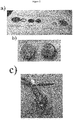
- the morphology of the MgNWs obtained in example 1 was analyzed by scanning electron microscopy (SEM) at an accelerating voltage of 4 kV ( figure 1 ).
- the as-grown MgNWs were evaluated as anodes in LiBs using a CR2032 coin cell in a half-cell configuration ( figure 2 ).
- MgNWs deposited on Cu foil was used as anode, Li as a counter and reference electrode and a Celgard separator soaked with 1M LiPF 6 in EC:DEC (1:1) as electrolyte.
- the different coin cells were employed to perform cyclic voltammetry curves and galvanostatic charge-discharge cycles at different scan rates and current densities as well as to evaluate their cycling stability. All measurements were performed in an argon filled glove box with oxygen and water levels less than 1 ppm at room temperature using a multichannel VMP3 potentiostat/galvanostat with EC-Lab software (Biologic, France).
- Figure 3a shows a cyclic voltammogram curve of a THF solution containing 0.25M PhMgBr with 0.005M TBAPF 6 electrolyte at a scan rate of 5 mVs -1 .
- the plot displays a pronounced reduction peak at -1.24V Vs Mg/Mg + associated to the Mg deposition potential, which was employed for the electrochemical deposition of MgNWs according to the experimental conditions described in the previous section. Subsequently, the as-grown electrode was used as anode in a half-cell configuration LiB.
- a characterization by CV was carried out in order to determine the different electrochemical process involved in the anode at different scan rates ranging from 0.01 mVs -1 to 0.15 mVs -1 at a potential window of 0.01 to -1.5V.
- the CV curves show two oxidation peaks at 0.2 and ⁇ 0.7V during the anodic scan in all the scan rates. Additionally, two reduction peaks at 0.2 and 0.7V were clearly evidenced at a very low scan rate of 0.01 mVs -1 . These peaks were attributed to the different lithiation-delithiation phases.
- the specific capacity of the battery was calculated from galvanostatic charge-discharge cycles at different current densities as illustrated in Figure 2c .
- the 3 electrode system experimental setup consists of two Mg strips (Sigma Aldrich) as counter and reference electrode along with a copper foil of 1 cm 2 working electrode.
- the electrochemical cell is filled with the electrolyte having 0.25 M PhMgBr and 0.005 M LiClO 4 as a supporting electrolyte.
- a Bio-Logic electrochemical workstation has been used to conduct the electrodeposition of Mg-Li alloy.
- a two steps electrodeposition process involving initially chronoamperometry at -1.24 V for 10 seconds is performed in order to create nucleation for the further growth of the nucleated Mg-Li alloy seeds by the consecutive chronopotentiometry step.
- a constant current 100 ⁇ A has been applied for 10 h period to form a nanostructured Mg-Li alloy. All the electrochemical deposition of Mg-Li alloy has been carried out under Ar gas filled in the glove box (JACOMEX).
- CR-2032 type coin cell has been used with the 1 x 1 cm of electrochemically deposited Mg-Li alloy working electrode against Li metal as counter and reference electrode with the electrolyte 1M LiPF 6 in EC:DEC (1:1).
- the fabricated cells were galvanostatically cycled at different scan rates (16, 32, 64, 100 and 166 mA/g) in a Bio-Logic electrochemical work station.
- the electrodeposited Mg-Li nanostructure is in particular nanoaggregates, more particularly like a leaf of a Cyprus tree, the growth of the nanostructure being found to be almost vertical.
- the length of the continuous nano structure varies in the range 7 to 11 ⁇ m, thickness is around 100 to 300 nm approximately.
- the incorporation of secondary metal Li + into the primary Mg 2+ crystal lattices enabled the formation of an alloy kind of phase. 10 to 15 unique Mg-Li nanostructures are present in the 8 ⁇ m 2 dimension. These measures values are advantageous to obtain a high tape density of the electrode and micrometer particles which are attributed for an advantageous capacity.
- the Mg-Li alloy electrode is having the material loading ⁇ 2 fold higher than what it is for MgNWs electrodes (both electrodeposited on Cu foil). A Li content of approximately 20% at was estimated into the Mg nanostructure.
- the prepared coin cell has been galvanostatically cycled (for example for 7 cycles) to study the Li ion insertion and desertion behavior at different current rates namely 16, 32, 64, 100 and 166 mA/g, and the specific capacities are 1005, 797, 431, 273 and 194 mAh/g respectively.
- the charge discharge curves indicate that the lithium insertion and desertion potential is comparatively in the lower region as that of the convention graphite, the same trend being observed in the MgNWs.
- the lithiation potential is at around 80 mV region and the major part of delithiation is observed at below 180 mV.
- the advantageous characteristics of this material is well suitable for the LIBs as a anode material due to its lower potential cycling with respect to Li reference, enable to achieve higher open circuit potential (OCV) of the full cell.
Landscapes
- Chemical & Material Sciences (AREA)
- Engineering & Computer Science (AREA)
- Chemical Kinetics & Catalysis (AREA)
- Electrochemistry (AREA)
- Materials Engineering (AREA)
- Metallurgy (AREA)
- Organic Chemistry (AREA)
- Power Engineering (AREA)
- General Chemical & Material Sciences (AREA)
- Microelectronics & Electronic Packaging (AREA)
- Crystallography & Structural Chemistry (AREA)
- Manufacturing & Machinery (AREA)
- Nanotechnology (AREA)
- Automation & Control Theory (AREA)
- Battery Electrode And Active Subsutance (AREA)
Abstract
Description
- The present invention relates to a process for the preparation of a Mg nanostructured material, in particular Mg nanowires, to the materials obtainable by this process and to their use in particular in electrodes for lithium batteries, supercapacitors, hydrogen storage, electronic detectors of chemical or biological substances or anti-microbial textiles.
- The rapid and growing evolution of consumer electronics in our society has triggered a great revolution in the field of energy storage due to their severe technical specifications in terms of high power and energy density as well as long lifespan. Accordingly, the need to find low-cost, safe and high-performance reliable solutions result critical to accomplish these commitments in the next coming years. In this regard, lithium-ion batteries (LiBs) based on nanostructured material anodes, such as nanowires, have emerged as promising anodes compared to graphite, employed commonly in commercial lithium-ion batteries. More specifically, tremendous efforts have currently been addressed to the domain of silicon nanowires (SiNWs) owing to its high theoretical charge capacity (4200 mAh g). However, in spite of the important advances carried out in SiNW-based lithium-ion batteries, an important drawback associated to their poor cycling performances limit nowadays their potential use in commercial applications, consequently exhaustive and deep studies are still required. Within this context, other interesting metal nanowires have attracted a great deal of attention as promising anode materials, such as Sn, Sb, Al or Mg. In particular, Mg presents a high theoretical specific capacity (3350 mAh g-1) and charge density (4355 mAh cm-3), which make him an excellent and promising candidate as anode for lithium-ion batteries.
- Over the past years, several works have been reported dealing with the electrochemical synthesis of metal nanowires, which provides an interesting approach due to its versatility, easy procedure, and synthesis at room temperature compared to other conventional techniques based on chemical vapor deposition or chemical etching. In this direction, for example, Sn, Sb or Al nanowires were conducted by means of a 3-electrode cell configuration using ionic liquid electrolytes in different substrates (or templates) at room temperature.
- Concerning Mg, electrochemically Mg nanowires have been synthesized using galvanostatic methods (constant current density of 5 mA cm-2) in a 2-electrode cell configuration constituted from a Pt cathode and a Mg anode (Chem. Commun. 2012, 48, 5169). However, the obtained coatings are not satisfactory in terms of density, uniformity, and adherence, which are critical in the above-mentioned applications.
- There has now been developed a process for the synthesis of Mg nanostructured material, in particular Mg nanowires, based on two steps, a first step related to a potentiostatic method, and a second step related to a galvanostatic method.
- Unexpectedly, it has been shown that this two steps method advantageously yields homogeneous and adherent coatings, with high densities of Mg nanostructured material, in particular Mg nanowires. This quality confers a very high specific surface to the material.
- As another advantage, said two steps method enables the direct electrochemical synthesis of Mg nanostructured material, in particular Mg nanowires, on substrates of interest, for example copper substrates, which are commonly used as current collectors in lithium-ion batteries. This represents an important advantage because it is not necessary to prepare a slurry by dispersing an active material, a conductive agent and a polymeric binder in a solvent, as described for instance by Cho et al. (Materials Research Bulletin 2013, 48, 2922). Thereby, the preparation of an anode electrode can be carried out directly on a battery device.
- In addition, the two steps method enables an easy control of the morphology of the Mg nanostructured material (shape, e.g. nanowires or nanoaggregates, density...), depending on the electrochemical conditions (e.g. current density, voltage, deposition time, concentration of electrolyte...).
- Furthermore, the Mg nanostructured material, for example the Mg nanowires of the invention, advantageously make it possible to yield excellent electrochemical performance as battery anode, and in particular to obtain excellent capacity retention with excellent coulombic efficiency, in particular by virtue of their great density.
- This Mg nanostructured material, in particular Mg nanowires, can be deposited in large quantities, by controlling electrochemical conditions through a safe and low synthesis cost by virtue of an easy synthesis method based on inexpensive reactants.
- Thus, a first subject matter of the invention relates to a process for the preparation of a Mg nanostructured material, comprising the steps of:
- i) submitting a conductive support to a potentiostatic step in presence of a Mg precursor and an electrolyte to obtain a deposit of Mg on said conductive support;
- ii) submitting the Mg deposit on said conductive support obtained in step i) to a galvanostatic step in presence of the Mg precursor and the electrolyte, whereby the Mg nanostructured material deposited on said conductive support is obtained; and
- iii) optionally, removing the conductive support and recovering the Mg nanostructured material obtained in step ii).
- The conductive support is in particular a metal or alloy, more particularly a metal or alloy selected from the group constituted of Cu, steel, for example stainless steel, and Al.
- The process of the invention enables the direct electrochemical synthesis of Mg nanostructured material, in particular Mg nanowires, on substrates of interest, which are for example commonly used as current collectors in lithium-ion batteries, with no need to transfer said Mg nanostructured material, in particular Mg nanowires.
- Said conductive support, in particular the metal or alloy, may be in the form of a foil.
- The electrolyte is in particular in solution in a polar organic solvent.
- Said polar organic solvent is in particular chosen from the group consisting of THF, dichloromethane, diethylether, ethylacetate, dimethylsulfoxide or acetonitrile.
- In a particular embodiment, the concentration of the electrolyte in the polar organic solvent is comprised from 0.0005 to 0.05M, more particularly from 0.001M to 0.01M, even more particularly of about 0.005M.
- The electrolyte can in particular be chosen from perchlorate containing salts, hexafluorophosphate containing salts, borate containing salts, and their mixtures.
- The electrolyte can in particular be chosen from Li containing salts, more particularly from perchlorate and Li containing salts, hexafluorophosphate and Li containing salts, borate and Li containing salts, and their mixtures.
- The electrolyte can more particularly be chosen from TBAPF6, LiClO4, and their mixtures.
- In particular, a Mg nanostructured material, i.e. a nanostructured material comprising or consisting of magnesium, notably Mg nanowires, i.e. nanowires comprising or consisting of magnesium, is obtained using TBAPF6 as an electrolyte.
- In particular, a Mg-Li alloy nanostructured material is obtained using as an electrolyte a Li containing salt, in particular LiClO4.
- The Mg precursor is preferably a Grignard reagent. The Grignard reagent may be chosen from alkyl, vinyl, and aryl-magnesium halides, in particular alkyl, vinyl, and aryl-magnesium iodides, bromides or chlorides, said Grignard reagent being more particularly PhMgBr.
- Stage i) consists in a potentiostatic step, and can be performed by any methods known for maintaining a constant electrode potential.
- Without wishing to be bound by theory, it is believed that stage i) enables to nucleate the conductive support surface with magnesium.
- The potentiostatic step is in particular based on chronoamperometry or chronocoulometry, more particularly on chronoamperometry at reduction potentials.
- The potentiostatic step is preferably performed at a reduction potential of +0.5 to -1.5 V, in particular of -1.0 to -1.5 V, more particularly of about -1.24 V.
- Stage i) is in particular performed for 1 to 10 seconds, in particular for 2 to 8 seconds, more particularly for about 5 seconds.
- Stage i) can also be performed for 1 to 20 seconds, in particular for 5 to 15 seconds, more particularly for about 10 seconds.
- Stage i) is carried out in particular at a temperature of 15 to 30°C, in particular of about 20 or 25°C.
- In a particular embodiment, step i) is performed in a 3 electrode cell configuration.
- In a more particular embodiment, step ii) is performed in a cell comprising a working electrode, a counter electrode and a reference electrode, the conductive support being used as the working electrode.
- For example, the counter electrode and a reference electrode comprise or consist of magnesium, in particular as a magnesium ribbon.
- By way of example, the potential as defined above is applied between the working electrode and the reference electrode.
- Stage ii) consists in a galvanostatic (e.g. chronopotentiometry) step, and can be performed by any methods known for maintaining a constant electrode current density.
- Without wishing to be bound by theory, it is believed that stage ii) enables the growth of the Mg nanostructured material from the Mg nuclei obtained in stage i).
enables to nucleate the conductive support surface with magnesium. - The galvanostatic step is in particular based on chronopotentiometry.
- The galvanostatic step is preferably performed at a constant current density of 75 to 150 µA/cm2, in particular of about 100 µA/cm2.
- Stage ii) is in particular performed for 4 to 20 hours, in particular for about 10 hours.
- Stage ii) is carried out in particular at a temperature of 15 to 30°C, in particular of about 20 or 25°C, preferably at the same temperature as the one of step i).
- In a particular embodiment, step ii) is performed in a 3 electrode cell configuration, preferably in the same cell that the one used in step i).
- In a more particular embodiment, step ii) is performed in a cell comprising a working electrode, a counter electrode and a reference electrode, the conductive support being used as the working electrode, the cell being preferably the same cell that the one used in step i).
- For example, the counter electrode and a reference electrode comprise or consist of magnesium, in particular as a magnesium ribbon.
- By way of example, the current density as defined above is applied to the working electrode and the counter electrode.
- Another subject matter of the invention relates to a Mg nanostructured material obtainable by the process as defined above.
- The Mg nanostructured material may be in contact, or not, with the conductive support as defined above.
- In a particular embodiment, said Mg nanostructured material comprises or is constituted of Mg nanowires. Mg nanowires are for example obtained using TBAPF6 as electrolyte.
- In a particular embodiment, said Mg nanostructured material comprises or is constituted of Mg nanoaggregates. Mg nanoaggregates are for example obtained using LiClO4 as electrolyte. The Mg of said Mg nanostructured material, in particular nanoaggregates, is notably an alloy of Mg and Li.
- Another subject matter of the invention relates to Mg nanowires, wherein said Mg nanowires are on a conductive support, and wherein said Mg nanowires cover at least 85% of the surface of said conductive support.
- Another subject matter of the invention relates to Mg nanowires, wherein said Mg nanowires are on a conductive support, and wherein said Mg nanowires cover said conductive support with a density of 1.2 1010 to 1.8 1010 Mg nanowires per cm2 of support, in particular of about 1.4 1010 nanowires by cm2 of support.
- The Mg nanowires as defined above have in particular a length of 1 to 10 µm, more particularly of 4 to 6 µm.
- The Mg nanowires as defined above have in particular a diameter of 10 to 100 nm, more particularly of 20 to 70 nm.
- The size of the nanowires, in particular their diameter and/or their length, can be measured according to conventional techniques, such as scanning electron microscopy and transmission electron microscopy.
- Typically, this diameter is homogeneous over the whole of the magnesium nanowires, that is to say that a standard deviation of less than 30% is observed in the distribution of the diameters.
- Another subject matter of the invention relates to a Mg-Li alloy nanostructured material. Said Mg-Li alloy nanostructured material is a nanostructured material comprising or consisting of Mg-Li alloy.
- The quantity of Li in the Mg-Li alloy is of 1 to 49% in mass, in particular of 10 to 30% atomic, more particularly of about 20% atomic (at%).
- In particular, said Mg-Li alloy nanostructured material is on a conductive support, and covers more particularly at least 85% of the surface of said conductive support.
- In particular, said Mg-Li alloy nanostructured material is on a conductive support, more particularly with a density of 1.2 1010 to 3.6 1010 Mg nanostructures per cm2 of support, for example of about 2.8 1010 nanostructures by cm2 of support.
- The Mg-Li alloy nanostructures as defined above have in particular a length of 1 to 25 µm, more particularly of 4 to 18 µm, even more particularly of 7 to 11 µm.
- The Mg-Li alloy nanostructures as defined above have in particular a thickness of 50 to 500 nm, more particularly of 100 to 300 nm.
- The size of the nanostructured material, in particular the length of the nanostructures and/or their length, can be measured according to conventional techniques, such as scanning electron microscopy and transmission electron microscopy.
- The Mg-Li alloy nanostructured material is in particular a Mg-Li alloy nanoaggregate, more particularly a cypress-leaf like materials
- Another subject matter of the present patent application relates to the use of a Mg or Mg-Li alloy nanostructured material as defined above or of Mg nanowires as defined above or of Mg or Mg-Li alloy nanoaggregates as defined above in the preparation of electrodes for energy storage, in particular for lithium batteries, supercapacitors or hydrogen storage.
- The Mg or Mg-Li alloy nanostructured material, for example the Mg nanowires and the Mg or Mg-Li alloy nanoaggregates of the invention, advantageously make it possible to yield excellent electrochemical performance as battery anode, and in particular to obtain excellent capacity retention with excellent coulombic efficiency, in particular by virtue of their great density. Furthermore, the lithiation potential can occur below 0.2 V which contributes for a better and higher open-circuit voltage (OCV) for the full cell configuration.
- The Mg or Mg-Li alloy nanostructured material according to the invention, in particular the Mg nanowires and the Mg or Mg-Li alloy nanoaggregates, are useful in particular in the preparation of anodes for lithium-metal, lithium-ion, lithium-air or lithium-sulfur batteries or other technologies of lithium or sodium batteries.
- The Mg or Mg-Li alloy nanostructured material according to the invention, in particular the Mg nanowires and the Mg or Mg-Li alloy nanoaggregates, are thus useful in particular in the preparation of anodes and/or cathodes of supercapacitors, micro-supercapacitors or ultramicrocapacitors.
- Another subject matter of the present patent application relates to the use of Mg or Mg-Li alloy nanostructured material, for example the Mg nanowires and the Mg or Mg-Li alloy nanoaggregates as defined above in the preparation of electrodes for electronic detectors of chemical or biological substances.
- Another subject matter of the present patent application relates to the use of Mg or Mg-Li alloy nanostructured material, for example the Mg nanowires and the Mg or Mg-Li alloy nanoaggregates as defined above in the preparation of anti-microbial textiles. As other nanostructured materials made of Zn or Ag, the Mg or Mg-Li alloy nanostructured material of the invention, for example the Mg nanowires and the Mg or Mg-Li alloy nanoaggregates as defined above, may be used in textiles for its anti-microbial activity.
- The following terms and expressions contained herein are defined as follows:
Unless otherwise indicated, all numbers expressing quantities of ingredients, properties such as size, weight, reaction conditions and so forth used in the specification and claims are to the understood as being modified in all instances by the term "about". - Accordingly, unless indicated to the contrary, the numerical parameters set forth in the following specification and attached claims are approximations that may vary depending upon the desired properties sought to be obtained by the invention. At the very least, and not as an attempt to limit the application of the doctrine of equivalents to the scope of the claims, each numerical parameter should at least be construed in light of the number of reported significant digits and by applying ordinary rounding techniques.
- As used herein, the term "about" means plus or minus 10% of the numerical value of the number with which it is being used. Therefore, about 50% means in the range of 45%-55%.
- As used herein, a range of values in the form "x-y" or "x to y", or "x through y", include integers x, y, and the integers therebetween. For example, the phrases "1-6", or "1 to 6" or "1 through 6" are intended to include the
integers - By "nanostructured material" is meant a material having at least one of its dimensions within nanometric scale, in particular sized from 1 to 100 nm.
- Said nanostructured material corresponds in particular to a nanomaterial, in particular a material having at least one of its dimensions sized from 1 to 100 nm.
- The material may comprise or be constituted of nanoparticles, nanothorns, nanopillars, nanowires or nanoaggregates.
- By "deposit of Mg" is meant the deposit of a material comprising or consisting of magnesium. In the first case, the Mg deposit comprises at least another compound. It may be a matter in particular of an alloy of Mg and Li, more particularly when the electrolyte is a Li containing salt.
- By "Mg nanostructured material" is meant a nanostructured material comprising or consisting of magnesium. In the first case, the Mg nanostructured material comprises at least another compound. It may be a matter in particular of an alloy of Mg and Li, more particularly when the electrolyte is a Li containing salt.
- "Nanowire" is understood to mean a wire, the diameter of which is less than 100 nm.
- The size of the nanowires, in particular their diameter and/or their length, can be measured according to conventional techniques, such as scanning electron microscopy and transmission electron microscopy.
- "Nanoaggregate" is understood to mean a nanomaterial resulting from the aggregation of particles of the same kind, in particular ions of the same kind, which nucleate and grow to form aggregates. Nanoaggregates of the invention are in particular cypress-leaf like Mg. Such cypress-leaf like materials are for example described in the case of Sb by Hou et al. (J. Mater. Chem. A, 2015, 3, 17549-17552).
- By "Mg precursor" is meant any compound that enable the deposit of magnesium on a support thanks to an electrochemical method.
- By "electrolyte" is in particular meant any compound that separates, once dissolved in an organic polar compound, into cations and anions.
- By "potentiostatic method" is meant a method enabling a constant electrode potential to be imposed.
- By "galvanostatic method" is meant a method enabling a constant electrode current density to be imposed.
- By "chronoamperometry" is meant a method wherein a potential step is applied to the working electrode and its resulting current is measured as a function of time. Chronoamperometry is thus a technique where a particular potential is imposed onto the working electrode and the resulting current is monitored with respect to time.
- By "chronocoulometry" is meant a method wherein a potential step is applied to the working electrode and its resulting charge is measured as a function of time. Chronocoulometry is a thus a technique where a particular potential is imposed onto the working electrode and the resulting charge is monitored with respect to time.
- By "chronopotentiometry" is meant a method wherein a current pulse is applied to the working electrode and its resulting potential is measured against a reference electrode as a function of time. Such a method is for instance described by S.-I. Pyun et al., Electrochemistry of Insertion Materials for Hydrogen and Lithium, . Chronopotentiometry is a thus technique where a particular current is imposed onto the working electrode and the resulting potential is monitored with respect to time.
- By "Mg-Li alloy" is meant any combination of Mg and Li, in particular obtained by electrodeposition from the Mg precursor and a Li containing salt as the electrolyte in a polar organic solvent. In particular, the quantity of Li in the Mg-Li alloy is below 50% in mass.
-
-
Figure 1 :
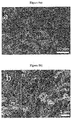
SEM images corresponding to the electrochemical deposition of Mg nanostructures on Cu substrates using a THF solution containing 0.25M PhMgBr in presence of a) 0.005 M TBAPF6 (figure 1a ), two different magnifications) and b) 0.005 M LiClO4 (figure 1b ), two different locations). -
Figure 1c ): Cross-sectional view of Mg nanowires under the conditions described in a).
All synthesis were carried out by using two steps, firstly chronoamperometry at - 1.24V during 2 seconds and subsequently a chronopotentiometry technique using a current density of 100 µA/cm2 during 10H. -
Figure 2 :-
Figure 2a ): Components employed for the coin cell device configuration (example 3); -
Figure 2b ): Assembled cell (Front and back side); and -
Figure 2c ): Electrical connections using a black case for the electrochemical performances (example 3).
-
-
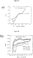
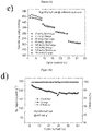
Figure 3 :-
Figure 3a ): Cyclic voltammetry curve (CV) of a THF solution containing 0.25M PhMgBr salt with 0.005M TBAPF6 using Cu foil as working electrode and Mg ribbon as counter and reference electrodes. Scan rate: 5 mVs-1 (example 3); -
Figure 3b ): CV curves of a LiB coin cell device using a half-cell configuration at different scan rates (example 3); -
Figure 3c ): Specific capacity calculated for the first seven cycles at different current densities (example 3); -
Figure 3d ): Specific capacity, efficiency and cycling stability of LiBs based on MgNW anodes in a half cell configuration using different current densities at 160 mA/g (example 3).
-
-
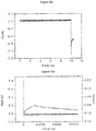
Figure 4 :-
Figure 4a ): Chronoamperometry curve of the electrochemical deposition of Mg-Li alloy experiment described in example 4. -
Figure 4b ): chronopotentiometry curves of the electrochemical deposition of Mg-Li alloy experiment described in example 4.
-
-
Figure 5 :-
Figure 5a represents the nanostructure dimensions after deposition, on a SEM image of the Mg-Li nanostructure prepared by electrodeposition technique on the Cu substrate; -
Figure 5b represents the density of the Mg-Li nano structure in a 8 µm square on a SEM image of the Mg-Li nanostructure prepared by electrodeposition technique on the Cu substrate.
-
-
Figure 6 :
Figure 6 represents the charge-discharge profile of the Mg-Li nanostructures of example 4 at different rates. - 3M PhMgBr (Sigma Aldrich), Mg ribbon 99.9 % (Sigma Aldrich), THF (Sigma Aldrich) and TEB-HFP (Sigma Aldrich) were used in these examples.
- The electrochemical synthesis of MgNWs was conducted in a 3 electrode cell configuration at room temperature using copper foil (1 cm2) as a working electrode and Mg ribbon as counter and reference electrodes respectively. A THF solution containing 0.25M PhMgBr salt with the 0.005M TBAPF6 was employed during the synthesis. The electrodeposition was carried out by means of a 2-step electrochemical procedure using both potentiostatic and galvanostatic methods. The former was employed to nucleate the Cu surface by applying a reduction potential of -1.24 V for a few seconds (chronoamperometry), and subsequently, the latter was used for growing the corresponding nanostructure applying a constant current of 100 µA/cm2 during 10h. All the electrochemical experiments were performed in an argon-filled glove box with oxygen and water levels less than 1 ppm.
- The same procedure was conducted with 0.005 M LiClO4 instead of 0.005M the TBAPF6, to yield a Mg nanostructured material in the form of nanoaggregates.
- The morphology of the MgNWs obtained in example 1 was analyzed by scanning electron microscopy (SEM) at an accelerating voltage of 4 kV (
figure 1 ). - The as-grown MgNWs, according to the electrochemical conditions mentioned in example 1, were evaluated as anodes in LiBs using a CR2032 coin cell in a half-cell configuration (
figure 2 ). MgNWs deposited on Cu foil was used as anode, Li as a counter and reference electrode and a Celgard separator soaked with 1M LiPF6 in EC:DEC (1:1) as electrolyte. The different coin cells were employed to perform cyclic voltammetry curves and galvanostatic charge-discharge cycles at different scan rates and current densities as well as to evaluate their cycling stability. All measurements were performed in an argon filled glove box with oxygen and water levels less than 1 ppm at room temperature using a multichannel VMP3 potentiostat/galvanostat with EC-Lab software (Biologic, France). -
Figure 3a shows a cyclic voltammogram curve of a THF solution containing 0.25M PhMgBr with 0.005M TBAPF6 electrolyte at a scan rate of 5 mVs-1. The plot displays a pronounced reduction peak at -1.24V Vs Mg/Mg+ associated to the Mg deposition potential, which was employed for the electrochemical deposition of MgNWs according to the experimental conditions described in the previous section. Subsequently, the as-grown electrode was used as anode in a half-cell configuration LiB. Firstly, a characterization by CV was carried out in order to determine the different electrochemical process involved in the anode at different scan rates ranging from 0.01 mVs-1 to 0.15 mVs-1 at a potential window of 0.01 to -1.5V. The CV curves show two oxidation peaks at 0.2 and ~0.7V during the anodic scan in all the scan rates. Additionally, two reduction peaks at 0.2 and 0.7V were clearly evidenced at a very low scan rate of 0.01 mVs-1. These peaks were attributed to the different lithiation-delithiation phases. The specific capacity of the battery was calculated from galvanostatic charge-discharge cycles at different current densities as illustrated inFigure 2c . Values ranging from 229 to 460 mAhg-1 were obtained from 33 to 166 mAg-1 with an excellent reversible capacity retention of approximately 93%. Cycling stability is another critical factor to characterize the performance of a battery. In this study, the lifetime of the device was evaluated by applying 50 galvanostatic charge-discharge cycles at a current density of 160 mAg-1 as shown in Figure 5d. Accordingly, a capacity retention of 80% with an excellent coulombic efficiency was observed during the cycling test. In overall, the results obtained in this study reflect the enormous potential of MgNWs to be employed as anodes in LiBs using a simple and low-cost process. - Advantageous lithiation behavior has been observed with the Mg-Li alloys formed electrochemically, in particular with the substituting lithium salt for the supporting electrolyte along with PhMgBr in THF solvent. Resulting specific capacities are 1005, 797, 431, 273 and 194 mAh/g for the current densities of 16, 32, 64, 100 and 166 mA/g respectively. This advantageous performance may be attributed from the better Li ion transport mechanism intrinsically in the alloy.
- The 3 electrode system experimental setup consists of two Mg strips (Sigma Aldrich) as counter and reference electrode along with a copper foil of 1 cm2 working electrode. The electrochemical cell is filled with the electrolyte having 0.25 M PhMgBr and 0.005 M LiClO4 as a supporting electrolyte. A Bio-Logic electrochemical workstation has been used to conduct the electrodeposition of Mg-Li alloy. A two steps electrodeposition process involving initially chronoamperometry at -1.24 V for 10 seconds is performed in order to create nucleation for the further growth of the nucleated Mg-Li alloy seeds by the consecutive chronopotentiometry step. Regarding the chronopotentiometry step, a constant current 100 µA has been applied for 10 h period to form a nanostructured Mg-Li alloy. All the electrochemical deposition of Mg-Li alloy has been carried out under Ar gas filled in the glove box (JACOMEX).
- CR-2032 type coin cell has been used with the 1 x 1 cm of electrochemically deposited Mg-Li alloy working electrode against Li metal as counter and reference electrode with the electrolyte 1M LiPF6 in EC:DEC (1:1). The fabricated cells were galvanostatically cycled at different scan rates (16, 32, 64, 100 and 166 mA/g) in a Bio-Logic electrochemical work station.
- The electrodeposited Mg-Li nanostructure is in particular nanoaggregates, more particularly like a leaf of a Cyprus tree, the growth of the nanostructure being found to be almost vertical.
- There are many void spaces in between the leaves morphology. The length of the continuous nano structure varies in the range 7 to 11 µm, thickness is around 100 to 300 nm approximately. The incorporation of secondary metal Li+ into the primary Mg2+ crystal lattices enabled the formation of an alloy kind of phase.
10 to 15 unique Mg-Li nanostructures are present in the 8 µm2 dimension. These measures values are advantageous to obtain a high tape density of the electrode and micrometer particles which are attributed for an advantageous capacity. The Mg-Li alloy electrode is having the material loading ∼2 fold higher than what it is for MgNWs electrodes (both electrodeposited on Cu foil). A Li content of approximately 20% at was estimated into the Mg nanostructure. - The prepared coin cell has been galvanostatically cycled (for example for 7 cycles) to study the Li ion insertion and desertion behavior at different current rates namely 16, 32, 64, 100 and 166 mA/g, and the specific capacities are 1005, 797, 431, 273 and 194 mAh/g respectively. The charge discharge curves indicate that the lithium insertion and desertion potential is comparatively in the lower region as that of the convention graphite, the same trend being observed in the MgNWs.
Significantly, the lithiation potential is at around 80 mV region and the major part of delithiation is observed at below 180 mV. The advantageous characteristics of this material is well suitable for the LIBs as a anode material due to its lower potential cycling with respect to Li reference, enable to achieve higher open circuit potential (OCV) of the full cell.
Claims (15)
- A process for the preparation of a Mg nanostructured material, comprising the steps of:i) submitting a conductive support to a potentiostatic step in presence of a Mg precursor and an electrolyte to obtain a deposit of Mg on said conductive support;ii) submitting the Mg deposit on said conductive support obtained in step i) to a galvanostatic step in presence of the Mg precursor and the electrolyte, whereby the Mg nanostructured material deposited on said conductive support is obtained; andiii) optionally, removing the conductive support and recovering the Mg nanostructured material obtained in step ii).
- The process according to claim 1, wherein the conductive support is a metal or alloy, in particular a metal or alloy selected from the group constituted of Cu, steel, in particular stainless steel, and Al.
- The process according to anyone of claims 1 to 2, wherein the electrolyte is chosen from TBAPF6 and LiClO4.
- The process according to anyone of claims 1 to 3, wherein the Mg precursor is a Grignard reagent, said Grignard reagent being in particular PhMgBr.
- The process according to anyone of claims 1 to 4, wherein the potentiostatic step is based on chronoamperometry or chronocoulometry, in particular on chronoamperometry at reduction potentials.
- The process according to claim 5, wherein the potentiostatic step is performed:- at a reduction potential of +0.5 to -1.5 V, in particular of -1.0 to -1.5 V, more particularly of about -1.24 V; and/or- for 1 to 10 seconds, in particular for 2 to 8 seconds, more particularly for about 5 seconds.
- The process according to anyone of claims 1 to 6, wherein the galvanostatic step is based on chronopotentiometry.
- The process according to claim 7, wherein the galvanostatic step is performed:- at a constant current density of 75 to 150 µA/cm2, in particular of about 100 µA/cm2; and/or- for 4 to 20 hours, in particular for about 10 hours.
- The process according to anyone of claims 1 to 8, wherein step i) and/or step ii) are performed at a temperature of 15 to 30°C, in particular of about 20 or 25°C, and/or in a 3 electrode cell configuration, in particular in a cell comprising a working electrode, a counter electrode and a reference electrode, the conductive support being used as the working electrode.
- Mg nanostructured material obtainable by the process according to anyone of claims 1 to 9, in particular said Mg nanostructured material comprising or being constituted of Mg nanowires or of Mg-Li alloy nanostructured material.
- Mg nanowires, wherein said Mg nanowires are on a conductive support, and wherein said Mg nanowires cover at least 85% of the surface of said conductive support, and/or wherein said Mg nanowires cover said conductive support with a density of 1.2 1010 to 1.8 1010 Mg nanowires per cm2 of support, in particular of about 1.4 1010 nanowires by cm2 of support.
- Mg nanowires according to anyone of claims 10 to 11, wherein said Mg nanowires have:- a length of 1 to 10 µm, in particular of 4 to 6 µm; and/or- a diameter of 10 to 100 nm, in particular of 20 to 70 nm.
- Mg-Li alloy nanostructured material, said Mg-Li alloy nanostructured material being in particular on a conductive support, and covers more particularly at least 85% of the surface of said conductive support, and/or with a density of 1.2 1010 to 3.6 1010 Mg nanostructures per cm2 of support, for example of about 2.8 1010 nanostructures by cm2 of support.
- Mg-Li alloy nanostructured material according to claim 10 or 13, wherein said Mg-Li alloy nanostructures have:- a length of 1 to 25 µm, in particular of 4 to 18 µm, more particularly of 7 to 11 µm; and/or- a thickness of 50 to 500 nm, more particularly of 100 to 300 nm.
- The use of a Mg or Mg-Li alloy nanostructured material according to claim 10, 13 or 14 or of Mg nanowires according to anyone of claims 11 to 12:- for energy storage, in particular in the preparation of electrodes for lithium batteries, supercapacitors or hydrogen storage; or- in the preparation of electrodes for electronic detectors of chemical or biological substances; or- in the preparation of anti-microbial textiles.
Applications Claiming Priority (1)
| Application Number | Priority Date | Filing Date | Title |
|---|---|---|---|
| EP17305663.1A EP3412797A1 (en) | 2017-06-06 | 2017-06-06 | Process for the preparation of a magnesium nanostructured material |
Publications (1)
| Publication Number | Publication Date |
|---|---|
| EP3412798A1 true EP3412798A1 (en) | 2018-12-12 |
Family
ID=59093504
Family Applications (2)
| Application Number | Title | Priority Date | Filing Date |
|---|---|---|---|
| EP17305663.1A Withdrawn EP3412797A1 (en) | 2017-06-06 | 2017-06-06 | Process for the preparation of a magnesium nanostructured material |
| EP18176295.6A Withdrawn EP3412798A1 (en) | 2017-06-06 | 2018-06-06 | Process for the preparation of a magnesium nanostructured material |
Family Applications Before (1)
| Application Number | Title | Priority Date | Filing Date |
|---|---|---|---|
| EP17305663.1A Withdrawn EP3412797A1 (en) | 2017-06-06 | 2017-06-06 | Process for the preparation of a magnesium nanostructured material |
Country Status (1)
| Country | Link |
|---|---|
| EP (2) | EP3412797A1 (en) |
Cited By (1)
| Publication number | Priority date | Publication date | Assignee | Title |
|---|---|---|---|---|
| CN110051350A (en) * | 2019-04-17 | 2019-07-26 | 深圳市脑潜能实业发展有限公司 | The preparation method and nanometer tow brain electrode of nanometer tow |
Families Citing this family (1)
| Publication number | Priority date | Publication date | Assignee | Title |
|---|---|---|---|---|
| CN113224387B (en) * | 2021-05-11 | 2022-05-10 | 河南大学 | Lithium-sulfur electrolyte added with Grignard reagent derivative, and preparation method and application thereof |
Citations (2)
| Publication number | Priority date | Publication date | Assignee | Title |
|---|---|---|---|---|
| US20120313587A1 (en) * | 2010-02-12 | 2012-12-13 | Washington Stat University Research Foundation | Lithium-ion batteries with nanostructured electrodes and associated methods of making |
| CN104846433A (en) * | 2015-04-23 | 2015-08-19 | 北京科技大学 | Method for high vacuum preparation of magnesium nano-wires |
-
2017
- 2017-06-06 EP EP17305663.1A patent/EP3412797A1/en not_active Withdrawn
-
2018
- 2018-06-06 EP EP18176295.6A patent/EP3412798A1/en not_active Withdrawn
Patent Citations (2)
| Publication number | Priority date | Publication date | Assignee | Title |
|---|---|---|---|---|
| US20120313587A1 (en) * | 2010-02-12 | 2012-12-13 | Washington Stat University Research Foundation | Lithium-ion batteries with nanostructured electrodes and associated methods of making |
| CN104846433A (en) * | 2015-04-23 | 2015-08-19 | 北京科技大学 | Method for high vacuum preparation of magnesium nano-wires |
Non-Patent Citations (4)
| Title |
|---|
| LASANTHA VIYANNALAGE ET AL: "From Grignard's reagents to well-defined Mg nanostructures: distinctive electrochemical and solution reduction routes", CHEMICAL COMMUNICATIONS - CHEMCOM., vol. 48, no. 42, 19 April 2012 (2012-04-19), pages 5169 - 5171, XP055426183, ISSN: 1359-7345, DOI: 10.1039/c2cc31405c * |
| SONG XIPING ET AL: "Preparation of magnesium nanowires by physical vapor deposition", 2016 IEEE 16TH INTERNATIONAL CONFERENCE ON NANOTECHNOLOGY (IEEE-NANO), IEEE, 22 August 2016 (2016-08-22), pages 261 - 263, XP033003756, DOI: 10.1109/NANO.2016.7751450 * |
| WANG MANG ET AL: "Electrodeposition of Mg doped ZnO thin film for the window layer of CIGS solar cell", APPLIED SURFACE SCIENCE, ELSEVIER, AMSTERDAM, NL, vol. 382, 19 April 2016 (2016-04-19), pages 217 - 224, XP029564014, ISSN: 0169-4332, DOI: 10.1016/J.APSUSC.2016.03.232 * |
| YAHUI SUN ET AL: "Synthesis of Magnesium Nanofibers by Electroless Reduction and their Hydrogen Interaction Properties", PARTICLE AND PARTICLE SYSTEMS CHARACTERIZATION., vol. 34, no. 4, 20 December 2016 (2016-12-20), DE, pages 1600276, XP055427177, ISSN: 0934-0866, DOI: 10.1002/ppsc.201600276 * |
Cited By (2)
| Publication number | Priority date | Publication date | Assignee | Title |
|---|---|---|---|---|
| CN110051350A (en) * | 2019-04-17 | 2019-07-26 | 深圳市脑潜能实业发展有限公司 | The preparation method and nanometer tow brain electrode of nanometer tow |
| CN110051350B (en) * | 2019-04-17 | 2020-04-07 | 深圳市脑潜能实业发展有限公司 | Preparation method of nano-filament bundle and nano-filament bundle brain electrode |
Also Published As
| Publication number | Publication date |
|---|---|
| EP3412797A1 (en) | 2018-12-12 |
Similar Documents
| Publication | Publication Date | Title |
|---|---|---|
| Meng et al. | Surface-alloyed nanoporous zinc as reversible and stable anodes for high-performance aqueous zinc-ion battery | |
| Li et al. | Phase-transition tailored nanoporous zinc metal electrodes for rechargeable alkaline zinc-nickel oxide hydroxide and zinc-air batteries | |
| Luo et al. | Dendrite-free lithium metal anode with lithiophilic interphase from hierarchical frameworks by tuned nucleation | |
| Han et al. | Toward highly reversible aqueous zinc-ion batteries: nanoscale-regulated zinc nucleation via graphene quantum dots functionalized with multiple functional groups | |
| Hoang et al. | Sustainable gel electrolyte containing pyrazole as corrosion inhibitor and dendrite suppressor for aqueous Zn/LiMn2O4 battery | |
| US20100021800A1 (en) | Carbon cathodes for fluoride ion storage | |
| Lee et al. | Byproduct reverse engineering to construct unusually enhanced protection layers for dendrite-free Zn anode | |
| US20110183205A1 (en) | Process for Fabricating a Silicon-Based Electrode, Silicon-Based Electrode and Lithium Battery Comprising Such an Electrode | |
| EP3199667B1 (en) | Method for producing silicon-plated metal plate | |
| EP1201004A1 (en) | Rechargeable electrochemical cell | |
| Li et al. | Low-temperature replacement construction of three-dimensional corrosion-resistant interface for deeply rechargeable Zn metal batteries | |
| Afzali et al. | Improved plating/stripping in anode-free lithium metal batteries through electrodeposition of lithiophilic zinc thin films | |
| Li et al. | Achieving stable Zn metal anode via a hydrophobic and Zn2+-conductive amorphous carbon interface | |
| WO2012050155A1 (en) | Electrodeposited material, active material for use in lithium secondary battery, and lithium secondary battery | |
| Chang et al. | Morphological and chemical mapping of columnar lithium metal | |
| Park et al. | Fabrication and characterization of Li-coated nickel mesh for anode of lithium-metal batteries | |
| WO2023173077A2 (en) | Superfast recharging zinc-based energy storage devices | |
| Shi et al. | Organothiols for dual-interface modification of high performance lithium-sulfur batteries | |
| Hsu et al. | One-step vapor–solid reaction growth of Sn@ C core–shell nanowires as an anode material for Li-ion batteries | |
| WO2012133214A1 (en) | Active material for lithium secondary battery, negative electrode for lithium secondary battery, and lithium secondary battery | |
| EP3412798A1 (en) | Process for the preparation of a magnesium nanostructured material | |
| JP2023525567A (en) | Electrolytic deposition of pure-phase SnSb from eutectic solution ethaline for sodium-ion and lithium-ion battery anodes. | |
| KR102238898B1 (en) | Protection of lithium-dendrite growth by functionalized carbon nanodot additives | |
| Lahiri et al. | Electrochemical synthesis of battery electrode materials from ionic liquids | |
| He et al. | Modulating the confined Na deposition via a carbon hollow tube decorated with in-situ formed sodiophilic NaZn13 alloys |
Legal Events
| Date | Code | Title | Description |
|---|---|---|---|
| PUAI | Public reference made under article 153(3) epc to a published international application that has entered the european phase |
Free format text: ORIGINAL CODE: 0009012 |
|
| STAA | Information on the status of an ep patent application or granted ep patent |
Free format text: STATUS: THE APPLICATION HAS BEEN PUBLISHED |
|
| AK | Designated contracting states |
Kind code of ref document: A1 Designated state(s): AL AT BE BG CH CY CZ DE DK EE ES FI FR GB GR HR HU IE IS IT LI LT LU LV MC MK MT NL NO PL PT RO RS SE SI SK SM TR |
|
| AX | Request for extension of the european patent |
Extension state: BA ME |
|
| STAA | Information on the status of an ep patent application or granted ep patent |
Free format text: STATUS: REQUEST FOR EXAMINATION WAS MADE |
|
| 17P | Request for examination filed |
Effective date: 20190611 |
|
| RBV | Designated contracting states (corrected) |
Designated state(s): AL AT BE BG CH CY CZ DE DK EE ES FI FR GB GR HR HU IE IS IT LI LT LU LV MC MK MT NL NO PL PT RO RS SE SI SK SM TR |
|
| STAA | Information on the status of an ep patent application or granted ep patent |
Free format text: STATUS: EXAMINATION IS IN PROGRESS |
|
| 17Q | First examination report despatched |
Effective date: 20210416 |
|
| STAA | Information on the status of an ep patent application or granted ep patent |
Free format text: STATUS: THE APPLICATION IS DEEMED TO BE WITHDRAWN |
|
| 18D | Application deemed to be withdrawn |
Effective date: 20240103 |