EP3412536A1 - Work vehicle and work vehicle control method - Google Patents
Work vehicle and work vehicle control method Download PDFInfo
- Publication number
- EP3412536A1 EP3412536A1 EP17806613.0A EP17806613A EP3412536A1 EP 3412536 A1 EP3412536 A1 EP 3412536A1 EP 17806613 A EP17806613 A EP 17806613A EP 3412536 A1 EP3412536 A1 EP 3412536A1
- Authority
- EP
- European Patent Office
- Prior art keywords
- joystick lever
- force
- steering
- assist torque
- work vehicle
- Prior art date
- Legal status (The legal status is an assumption and is not a legal conclusion. Google has not performed a legal analysis and makes no representation as to the accuracy of the status listed.)
- Granted
Links
Images











Classifications
-
- B—PERFORMING OPERATIONS; TRANSPORTING
- B62—LAND VEHICLES FOR TRAVELLING OTHERWISE THAN ON RAILS
- B62D—MOTOR VEHICLES; TRAILERS
- B62D5/00—Power-assisted or power-driven steering
- B62D5/06—Power-assisted or power-driven steering fluid, i.e. using a pressurised fluid for most or all the force required for steering a vehicle
- B62D5/09—Power-assisted or power-driven steering fluid, i.e. using a pressurised fluid for most or all the force required for steering a vehicle characterised by means for actuating valves
-
- B—PERFORMING OPERATIONS; TRANSPORTING
- B62—LAND VEHICLES FOR TRAVELLING OTHERWISE THAN ON RAILS
- B62D—MOTOR VEHICLES; TRAILERS
- B62D5/00—Power-assisted or power-driven steering
- B62D5/06—Power-assisted or power-driven steering fluid, i.e. using a pressurised fluid for most or all the force required for steering a vehicle
- B62D5/09—Power-assisted or power-driven steering fluid, i.e. using a pressurised fluid for most or all the force required for steering a vehicle characterised by means for actuating valves
- B62D5/091—Hydraulic steer-by-wire systems, e.g. the valve being actuated by an electric motor
-
- B—PERFORMING OPERATIONS; TRANSPORTING
- B62—LAND VEHICLES FOR TRAVELLING OTHERWISE THAN ON RAILS
- B62D—MOTOR VEHICLES; TRAILERS
- B62D1/00—Steering controls, i.e. means for initiating a change of direction of the vehicle
- B62D1/02—Steering controls, i.e. means for initiating a change of direction of the vehicle vehicle-mounted
- B62D1/12—Hand levers
-
- B—PERFORMING OPERATIONS; TRANSPORTING
- B62—LAND VEHICLES FOR TRAVELLING OTHERWISE THAN ON RAILS
- B62D—MOTOR VEHICLES; TRAILERS
- B62D12/00—Steering specially adapted for vehicles operating in tandem or having pivotally connected frames
-
- B—PERFORMING OPERATIONS; TRANSPORTING
- B62—LAND VEHICLES FOR TRAVELLING OTHERWISE THAN ON RAILS
- B62D—MOTOR VEHICLES; TRAILERS
- B62D5/00—Power-assisted or power-driven steering
- B62D5/06—Power-assisted or power-driven steering fluid, i.e. using a pressurised fluid for most or all the force required for steering a vehicle
- B62D5/20—Power-assisted or power-driven steering fluid, i.e. using a pressurised fluid for most or all the force required for steering a vehicle specially adapted for particular type of steering gear or particular application
- B62D5/28—Power-assisted or power-driven steering fluid, i.e. using a pressurised fluid for most or all the force required for steering a vehicle specially adapted for particular type of steering gear or particular application for pivoted bogies
-
- B—PERFORMING OPERATIONS; TRANSPORTING
- B62—LAND VEHICLES FOR TRAVELLING OTHERWISE THAN ON RAILS
- B62D—MOTOR VEHICLES; TRAILERS
- B62D6/00—Arrangements for automatically controlling steering depending on driving conditions sensed and responded to, e.g. control circuits
- B62D6/008—Control of feed-back to the steering input member, e.g. simulating road feel in steer-by-wire applications
-
- E—FIXED CONSTRUCTIONS
- E02—HYDRAULIC ENGINEERING; FOUNDATIONS; SOIL SHIFTING
- E02F—DREDGING; SOIL-SHIFTING
- E02F9/00—Component parts of dredgers or soil-shifting machines, not restricted to one of the kinds covered by groups E02F3/00 - E02F7/00
- E02F9/08—Superstructures; Supports for superstructures
-
- E—FIXED CONSTRUCTIONS
- E02—HYDRAULIC ENGINEERING; FOUNDATIONS; SOIL SHIFTING
- E02F—DREDGING; SOIL-SHIFTING
- E02F9/00—Component parts of dredgers or soil-shifting machines, not restricted to one of the kinds covered by groups E02F3/00 - E02F7/00
- E02F9/08—Superstructures; Supports for superstructures
- E02F9/0841—Articulated frame, i.e. having at least one pivot point between two travelling gear units
-
- E—FIXED CONSTRUCTIONS
- E02—HYDRAULIC ENGINEERING; FOUNDATIONS; SOIL SHIFTING
- E02F—DREDGING; SOIL-SHIFTING
- E02F9/00—Component parts of dredgers or soil-shifting machines, not restricted to one of the kinds covered by groups E02F3/00 - E02F7/00
- E02F9/20—Drives; Control devices
- E02F9/2004—Control mechanisms, e.g. control levers
-
- E—FIXED CONSTRUCTIONS
- E02—HYDRAULIC ENGINEERING; FOUNDATIONS; SOIL SHIFTING
- E02F—DREDGING; SOIL-SHIFTING
- E02F9/00—Component parts of dredgers or soil-shifting machines, not restricted to one of the kinds covered by groups E02F3/00 - E02F7/00
- E02F9/20—Drives; Control devices
- E02F9/22—Hydraulic or pneumatic drives
- E02F9/225—Control of steering, e.g. for hydraulic motors driving the vehicle tracks
-
- G—PHYSICS
- G01—MEASURING; TESTING
- G01L—MEASURING FORCE, STRESS, TORQUE, WORK, MECHANICAL POWER, MECHANICAL EFFICIENCY, OR FLUID PRESSURE
- G01L5/00—Apparatus for, or methods of, measuring force, work, mechanical power, or torque, specially adapted for specific purposes
- G01L5/22—Apparatus for, or methods of, measuring force, work, mechanical power, or torque, specially adapted for specific purposes for measuring the force applied to control members, e.g. control members of vehicles, triggers
- G01L5/223—Apparatus for, or methods of, measuring force, work, mechanical power, or torque, specially adapted for specific purposes for measuring the force applied to control members, e.g. control members of vehicles, triggers to joystick controls
-
- B—PERFORMING OPERATIONS; TRANSPORTING
- B62—LAND VEHICLES FOR TRAVELLING OTHERWISE THAN ON RAILS
- B62D—MOTOR VEHICLES; TRAILERS
- B62D12/00—Steering specially adapted for vehicles operating in tandem or having pivotally connected frames
- B62D12/02—Steering specially adapted for vehicles operating in tandem or having pivotally connected frames for vehicles operating in tandem
-
- B—PERFORMING OPERATIONS; TRANSPORTING
- B62—LAND VEHICLES FOR TRAVELLING OTHERWISE THAN ON RAILS
- B62D—MOTOR VEHICLES; TRAILERS
- B62D6/00—Arrangements for automatically controlling steering depending on driving conditions sensed and responded to, e.g. control circuits
- B62D6/08—Arrangements for automatically controlling steering depending on driving conditions sensed and responded to, e.g. control circuits responsive only to driver input torque
- B62D6/10—Arrangements for automatically controlling steering depending on driving conditions sensed and responded to, e.g. control circuits responsive only to driver input torque characterised by means for sensing or determining torque
Definitions
- the present invention relates to a work vehicle and to a method for controlling a work vehicle.
- Patent Literature 1 and 2 are provided with a steering valve that adjusts the flow of fluid supplied to a hydraulic actuator according to an inputted pilot pressure, and a pilot valve that adjusts the pilot pressure to be supplied to the steering valve.
- the pilot valve is provided with an operation input shaft and a feedback input shaft, which are able to rotate relative to each other.
- the operation input shaft is linked to the joystick lever and rotates according to the rotation angle of the joystick lever.
- the feedback input shaft is linked to the front frame by a link mechanism, and rotates according to the change in the steering angle.
- This pilot valve adjusts the pilot pressure inputted to the steering valve according to the difference between the rotation angle of the operation input shaft and the rotation angle of the feedback input shaft.
- the flow of fluid supplied from the steering valve to the hydraulic actuator is changed according to the adjusted pilot pressure, and the steering angle is changed.
- the operator can change the steering angle by merely pushing on the joystick lever with the light operating force necessary for changing the open or closed state of the port of the pilot valve.
- the joystick lever is provided with a play angle. Therefore, within the angular range of play, the vehicle body will not bend even if the joystick lever is moved, and only once the play angle is exceeded will the spool of the steering valve open and the body begin to bend.
- the work vehicle according to the first invention is an articulated work vehicle in which a front frame and a rear frame are linked, said work vehicle comprising a joystick lever, a hydraulic actuator, a control valve, a force imparting component, and a controller.
- the joystick lever is operated by the operator and allows the target steering angle to be set.
- the hydraulic actuator is driven by hydraulic pressure and performs an articulation for changing the actual steering angle of the front frame with respect to the rear frame in response to operation of the joystick lever.
- the control valve controls the flow of fluid supplied to the hydraulic actuator so as to make the actual steering angle coincide with the target steering angle.
- the force imparting component imparts an assisting force or counterforce to the operation of the joystick lever.
- the controller controls the force imparting component so as to generate resistance against the operation of the joystick lever on the basis of the start timing of the articulation.
- the resistance against the joystick lever may be generated at the start timing of the articulation, or may be before the start timing or after the start timing.
- the work vehicle according to the second invention is the work vehicle according to the first invention, wherein the controller controls the force imparting component so as to generate resistance to the operation of the joystick lever from a first position of the joystick lever in a state in which the deviation angle between the target steering angle and the actual steering angle is zero, to a second position of the joystick lever at which the articulation begins.
- the vehicle body can be bent slightly by moving the joystick lever just a little from the position where the resistance was felt, making it easy to perform fine operations.
- the work vehicle according to the third invention is the work vehicle according to the first invention, wherein the controller generates resistance to the operation of the joystick lever by decreasing the assisting force or increasing the counterforce.
- the work vehicle according to the fourth invention is the work vehicle according to the first invention, further comprising a steering valve that adjusts the flow of fluid supplied to the hydraulic actuator on the basis of a pilot pressure inputted from the control valve.
- the control valve controls the flow of fluid supplied from the steering valve to the hydraulic actuator by adjusting the pilot pressure.
- the controller controls the force imparting component so that the opening timing of the steering valve falls within the period during which the resistance is generated.
- the work vehicle according to the fifth invention is the work vehicle according to the first invention, wherein the control valve has a first input member, a second input member, and a biasing component.
- the first input member is displaced according to the target steering angle.
- the second input member is displaced according to the actual steering angle.
- the biasing component biases the first input member so that the amount of displacement of the first input member coincides with the amount of displacement of the second input member.
- the difference between the amount of displacement of the first input member and the amount of displacement of the second input member corresponds to the deviation angle between the target steering angle and the actual steering angle.
- the joystick lever is operated against the biasing force of the biasing component.
- control valve is thus provided with a biasing component, and the operator operates the joystick lever with an operating force that goes against the biasing force produced by the biasing component.
- the force imparting component is controlled so as to generate resistance to operation against this biasing force.
- the work vehicle according to the sixth invention is the work vehicle according to the first invention, further comprising a timing sensor that senses the timing at which the generation of resistance is started, which is preset on the basis of the start timing of the articulation.
- the controller controls the force imparting component so as to start generating resistance against the operation of the joystick lever when the timing sensor senses this timing.
- the work vehicle according to the seventh invention is the work vehicle according to the sixth invention, wherein the timing sensor has a target steering angle sensor that senses the target steering angle, and an actual steering angle sensor that senses the actual steering angle.
- the controller controls the force imparting component so as to start the generation of resistance against the operation of the joystick lever at the point when the deviation angle calculated from the sensing value of the target steering angle sensor and the sensing value of the actual steering angle sensor reaches a specific value preset on the basis of the start timing of the articulation.
- the work vehicle according to the eighth invention is the work vehicle according to the sixth invention, further comprising a steering valve that adjusts the flow of fluid supplied to the hydraulic actuator on the basis of the pilot pressure inputted from the control valve.
- the control valve controls the flow of fluid supplied from the steering valve to the hydraulic actuator by adjusting the pilot pressure.
- articulation can be started by operating the joystick lever to move the control valve and adjust the pilot pressure.
- the work vehicle according to the ninth invention is the work vehicle according to the eighth invention, wherein the timing sensor senses the position of the valve body of the steering valve.
- the controller controls the force imparting component so as to start the generation of resistance against the operation of the joystick lever at the point when the position of the valve body sensed by the timing sensor reaches a specific value set in advance on the basis of the start timing of the articulation.
- the work vehicle according to the tenth invention is the work vehicle according to the eighth invention, wherein the timing sensor senses the pilot pressure.
- the controller controls the force imparting component so as to start the generation of resistance against the operation of the joystick lever at the point when the pilot pressure sensed by the timing sensor reaches a specific value preset on the basis of the start timing of the articulation.
- the work vehicle according to the eleventh invention is the work vehicle according to the eighth invention, further comprising a pump that supplies fluid to the hydraulic actuator via the steering valve.
- the timing sensor senses the load pressure on the pump.
- the controller controls the force imparting component so as to start the generation of resistance against the operation of the joystick lever at the point when the load pressure on the pump sensed by the timing sensor reaches a specific value set in advance on the basis of the start timing of the articulation.
- the work vehicle according to the twelfth invention is the work vehicle according to the first invention, further comprising a torque sensor that senses the torque produced by operation of the joystick lever.
- the force imparting component has an electric motor as a drive source.
- the controller controls the force imparting component on the basis of the value sensed by the torque sensor.
- a force can be applied according to the torque applied by the operator to the joystick lever.
- the imparted force can be controlled so that when the torque applied to the joystick lever by the operator is high, the assisting force imparted by the imparting component is increased, and when the torque is low, the assisting force is decreased.
- the work vehicle according to the thirteenth invention is the work vehicle according to the seventh invention, further comprising a torque sensor that senses the torque produced by operation of the joystick lever.
- the force imparting component has an electric motor as a drive source.
- the controller has a calculator and an operation controller.
- the calculator calculates the force to be imparted to the operation of the joystick lever by matching the imparted force that is preset for the sensed torque to an imparted force that is preset for the deviation angle.
- the operation controller operates the force imparting component so that the calculated force will be imparted.
- the work vehicle according to the fourteenth invention is the work vehicle according to the ninth invention, further comprising a torque sensor that senses the torque produced by operation of the joystick lever.
- the force imparting component has an electric motor as a drive source.
- the controller has a calculator and an operation controller.
- the calculator calculates the force to be imparted to the operation of the joystick lever by matching the imparted force that is preset for the torque to an imparted force that is preset for the position of the valve body.
- the operation controller operates the force imparting component so that the calculated force will be imparted.
- the work vehicle according to the fifteenth invention is the work vehicle according to the tenth invention, further comprising a torque sensor that senses the torque produced by operation of the joystick lever.
- the force imparting component has an electric motor as a drive source.
- the controller has a calculator and an operation controller.
- the calculator calculates the force to be imparted against the operation of the joystick lever by matching the imparted force that is preset for the torque to an imparted force that is preset for the pilot pressure.
- the operation controller operates the force imparting component so that the calculated force will be imparted.
- the work vehicle according to the sixteenth invention is the work vehicle according to the eleventh invention, further comprising a torque sensor that senses the torque produced by operation of the joystick lever.
- the force imparting component has an electric motor as a drive source.
- the controller has a calculator and an operation controller.
- the calculator calculates the force to be imparted against the operation of the joystick lever by matching the imparted force that is preset for the torque to an imparted force that is preset for the load pressure on the pump.
- the operation controller operates the force imparting component so that the calculated force will be imparted.
- the work vehicle according to the seventeenth invention is the work vehicle according to any of the fourteenth to sixteenth inventions, further comprising a speed sensor that senses the speed of the work vehicle.
- the imparted force preset for the torque is varied on the basis of the speed sensed by the speed sensor.
- the work vehicle according to the eighteenth invention is the work vehicle according to any of the first to seventeenth inventions, wherein the control valve is linked to the joystick lever.
- the method for controlling a work vehicle is a method for controlling an articulated work vehicle in which a front frame and a rear frame are linked, comprising a first acquisition step, a generation step, and a transmission step.
- the first acquisition step involves acquiring a first signal from a timing sensor that senses the start timing of an articulation.
- the generation step involves generating a second signal for generating resistance against the operation of a joystick lever on the basis of the first signal.
- the transmission step involves transmitting the second signal to a force imparting component that imparts an assisting force or a counterforce to the operation of the joystick lever.
- the resistance to the joystick lever may be generated at the start of the articulation, or may be before or after the start.
- the work vehicle control method according to the twentieth invention is the work vehicle control method according to the nineteenth invention, further comprising a second acquisition step.
- This second acquisition step involves acquiring a third signal from a torque sensor that senses the torque produced by operation of the joystick lever.
- the generation step comprises a first determination operation, a second determination operation, and a computation operation.
- the first determination operation the counterforce to be imparted to the operation of the joystick lever is determined on the basis of the first signal, and a fourth signal is outputted.
- the second determination operation the assisting force or counterforce to be imparted to the operation of the joystick lever is determined on the basis of the third signal, and a fifth signal is outputted.
- the computation operation the counterforce indicated by the fourth signal and the assisting force or counterforce indicated by the fifth signal are added together to generate the second signal.
- the present invention provides a work vehicle and a method for controlling a work vehicle with which it is easy to perform fine operations.
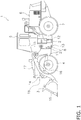
- FIG. 1 is a simplified diagram of the configuration of a wheel loader 1 in this embodiment.
- the wheel loader 1 in this embodiment comprises a body frame 2, a work implement 3, a pair of front tires 4, a cab 5, an engine compartment 6, a pair of rear tires 7, and a steering operation device 8 (see FIG. 2 described below).
- the wheel loader 1 uses the work implement 3 to load earth and perform other such work.
- the body frame 2 is what is called an articulated type, and has a front frame 11, a rear frame 12, and a connecting shaft 13.
- the front frame 11 is disposed ahead of the rear frame 12.
- the connecting shaft 13 is provided in the center in the vehicle width direction, and links the front frame 11 and the rear frame 12 so that they can pivot relative to each other.
- the front tires 4 are mounted on the left and right sides of the front frame 11.
- the rear tires 7 are mounted on the left and right sides of the rear frame 12.
- the work implement 3 is driven by hydraulic fluid from a work implement pump (not shown).
- the work implement 3 has a boom 14, a bucket 15, a lift cylinder 16, and a bucket cylinder 17.
- the boom 14 is mounted on the front frame 11.
- the bucket 15 is attached to the distal end of the boom 14.
- the lift cylinder 16 and the bucket cylinder 17 are hydraulic cylinders. One end of the lift cylinder 16 is attached to the front frame 11, and the other end of the lift cylinder 16 is attached to the boom 14. The expansion and contraction of the lift cylinder 16 causes the boom 14 to pivot up and down. One end of the bucket cylinder 17 is attached to the front frame 11, and the other end of the bucket cylinder 17 is attached to the bucket 15 via a bell crank 18. As the bucket cylinder 17 expands and contracts, the bucket 15 pivots up and down.
- the cab 5 is mounted on the rear frame 12, and in its interior are disposed a steering wheel or a joystick lever 24 (see FIG. 2 described below) for a steering operation, a lever for operating the work implement 3, various display devices, and the like.
- the engine compartment 6 is disposed on the rear frame 12 to the rear of the cab 5, and houses an engine.
- the steering operation device 8 will be described in detail below, but has steering cylinders 21 and 22, and when the flow of fluid supplied to the steering cylinders 21 and 22 is changed, this changes the steering angle of the front frame 11 with respect to the rear frame 12, thereby changing the traveling direction of the wheel loader 1.
- FIG. 2 is a hydraulic circuit diagram of the configuration of the steering operation device 8.
- the steering operation device 8 in this embodiment mainly has the pair of steering cylinders 21 and 22, a steering hydraulic circuit 23, the joystick lever 24, a connecting portion 25, a link mechanism 26, a force imparting component 27, a controller 28, and a timing sensor 29.
- the steering cylinders 21 and 22 are driven by hydraulic pressure.
- the steering cylinders 21 and 22 are disposed side by side on the left and right sides in the vehicle width direction, with the connecting shaft 13 in between.
- the steering cylinder 21 is disposed on the left side of the connecting shaft 13 (see FIG. 1 ).
- the steering cylinder 22 is disposed on the right side of the connecting shaft 13.
- One end of each of the steering cylinders 21 and 22 is attached to the front frame 11, and the other end is attached to the rear frame 12.
- the steering cylinder 21 is provided with an extension port 21a and a contraction port 21b
- the steering cylinder 22 is provided with an extension port 22a and a contraction port 22b.
- a steering angle sensor 104 that senses the steering angle ⁇ s is provided near the connecting shaft 13 disposed between the steering cylinders 21 and 22.
- the steering angle sensor 104 is constituted by a potentiometer, for example, and the sensed steering angle ⁇ s is sent to the controller 28 as a sensing signal.
- the steering cylinder 21 is provided with a cylinder stroke sensor 106 for sensing the stroke of the cylinder, and the steering cylinder 22 is provided with a cylinder stroke sensor 107 for sensing the stroke of that cylinder.
- the sensed values of the cylinder stroke sensors 106 and 107 may be sent to the controller 28 and to find the steering angle ⁇ s.
- the steering hydraulic circuit 23 is a hydraulic circuit for adjusting the flow of fluid supplied to the steering cylinders 21 and 22.
- the steering hydraulic circuit 23 has a main hydraulic circuit 30 and a pilot hydraulic circuit 40.
- the main hydraulic circuit 30 is a circuit that supplies fluid from a main hydraulic pressure source 31 to the steering cylinders 21 and 22, and has a steering valve 32.
- the main hydraulic pressure source 31 is made up of a hydraulic pump, a relief valve, and the like.
- the steering valve 32 is a spool type of valve, and is a flow control valve that adjusts the flow of fluid supplied to the steering cylinders 21 and 22 according to the inputted pilot pressure.
- the steering valve 32 has a main pump port P1, a main drain port P2, a first steering port P3, and a second steering port P4.
- the main pump port P1 is connected to the main hydraulic pressure source 31 via a main hydraulic line 36.
- the main drain port P2 is connected to a drain tank DT that collects fluid via the main drain line 37.
- the first steering port P3 is connected to the contraction port 21b of the steering cylinder 21 and the extension port 22a of the steering cylinder 22 via a first steering line 38.
- the second steering port P4 is connected to the extension port 21a of the steering cylinder 21 and the contraction port 22b of the steering cylinder 22 via a second steering line 39.
- the steering valve 32 has a valve body 33 that can move between a neutral position Ns, a left steering position Ls, and a right steering position Rs.
- the valve body 33 When the valve body 33 is disposed in the neutral position Ns, the main pump port P1 and the main drain port P2 are communicating with each other. In this case, the first steering port P3 and the second steering port P4 are not in communication with either port.
- the valve body 33 When the valve body 33 is disposed in the left steering position Ls, the main pump port P1 and the first steering port P3 are communicating with each other, and the main drain port P2 and the second steering port P4 are communicating with each other.
- the valve body 33 When the valve body 33 is disposed in the right steering position Rs, the main pump port P1 and the second steering port P4 are communicating with each other, and the main drain port P2 and the first steering port P3 are communicating with each other.
- the steering valve 32 has a first pilot chamber 34 and a second pilot chamber 35.
- the valve body 33 When pilot pressure is not being supplied to the first pilot chamber 34 or the second pilot chamber 35, and when the same pilot pressure is being supplied to the first pilot chamber 34 and the second pilot chamber 35, the valve body 33 is located in the neutral position Ns.
- the valve element 33 In a state in which the pilot pressure is being supplied only to the first pilot chamber 34, the valve element 33 is located in the left steering position Ls.
- the valve element 33 In a state in which the pilot pressure is supplied only to the second pilot chamber 35, the valve element 33 is located in the right steering position Rs.
- the steering valve 32 changes the opening surface area through which the fluid from the main hydraulic pressure source 31 passes, according to the supplied pilot pressure. Accordingly, the steering valve 32 controls the flow of fluid supplied to the steering cylinder 21 or the steering cylinder 22 according to the pilot pressure.
- the pilot hydraulic circuit 40 is a circuit for supplying fluid from a pilot hydraulic pressure source 43 to the first pilot chamber 34 and the second pilot chamber 35 of the steering valve 32.
- the pilot hydraulic circuit 40 has a variable pressure reducer 41 and a pilot valve 42.
- the variable pressure reducer 41 reduces and adjusts the hydraulic pressure sent from the pilot hydraulic pressure source 43 to the pilot valve 42.
- the variable pressure reducer 41 has a built-in electromagnetic pressure reducing valve, and receives a command signal from the controller 28 to control the hydraulic pressure.
- the pilot valve 42 is a rotary type of valve that adjusts the pilot pressure inputted from the pilot hydraulic pressure source 43 to the steering valve 32.
- the rotary pilot valve 42 has a pilot pump port P5, a pilot drain port P6, a first pilot port P7, and a second pilot port P8.
- the pilot pump port P5 is connected to the variable pressure reducer 41 via the pilot hydraulic line 44, and the variable pressure reducer 41 is connected to the pilot hydraulic pressure source 43.
- the pilot drain port P6 is connected to the drain tank DT that collects fluid via a pilot drain line 45.
- the first pilot port P7 is connected to the first pilot chamber 34 of the steering valve 32 via the first pilot line 46.
- the second pilot port P8 is connected to the second pilot chamber 35 of the steering valve 32 via the second pilot line 47.
- the pilot valve 42 has a valve body 60 including an operation spool 71 and an operation sleeve 72. With the operation sleeve 72 serving as a reference, the operation spool 71 has a neutral position Np, a left pilot position Lp, and a right pilot position Rp.
- the pilot pump port P5, the pilot drain port P6, the first pilot port P7, and the second pilot port P8 communicate with each other.
- the pilot pump port P5 communicates with the first pilot port P7
- the pilot drain port P6 and the second pilot port P8 communicate with each other.
- the pilot pump port P5 and the second pilot port P8 communicate with each other, and the pilot drain port P6 and the first pilot port P7 communicate with each other.
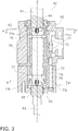
- FIG. 3 is a cross sectional configuration diagram of the pilot valve 42.
- the pilot valve 42 mainly has the valve body 60, an operation input shaft 61, a feedback input shaft 62, a housing 63, a first spring 64, a second spring 65, and a feedback component 66.
- the operation input shaft 61 is provided rotatably around its center axis O, and is inserted into the housing 63.
- the operation input shaft 61 is connected to the joystick lever 24 (discussed below) via the connecting portion 25.
- the operation input shaft 61 rotates to the left and right at the same rotation angle as the rotation angle ⁇ in of the joystick lever 24.
- the feedback input shaft 62 is disposed coaxially with the operation input shaft 61, and is provided rotatably around the center axis O.
- the feedback input shaft 62 is inserted into the housing 63 so as to be opposite the operation input shaft 61.
- the feedback input shaft 62 is connected to the front frame 11 via the link mechanism 26 (discussed below), and rotates at the same rotation angle as the steering angle ⁇ s of the front frame 11 with respect to the rear frame 12.
- a substantially cylindrical space is formed in the housing 63, and the operation input shaft 61 and the feedback input shaft 62 are inserted as described above.
- the housing 63 houses the valve body 60 and the feedback component 66, and the pilot pump port P5, the pilot drain port P6, the first pilot port P7, and the second pilot port P8 are formed in the housing 63.
- the valve body 60 has the operation spool 71 and the operation sleeve 72, and moves into the neutral position Np, the left pilot position Lp, and the right pilot position Rp when the operation spool 71 rotates with respect to the operation sleeve 72.
- the operation spool 71 is substantially cylindrical in shape and is disposed coaxially with the operation input shaft 61, and is connected to the operation input shaft 61.
- the joystick lever 24 is connected to the operation input shaft 61 via the connecting portion 25 (discussed below), and when the operator operates the joystick lever 24 to the right side by the rotation angle ⁇ in, the operation input shaft 61 and the operation spool 71 also rotate to the right around the center axis O by the rotation angle ⁇ in.
- Slits 71a and 71b are formed in the operation spool 71 near the operation input shaft 61 along the circumferential direction at two opposing positions so as to sandwich the center axis O in between.
- the operation sleeve 72 has a substantially cylindrical shape and is disposed outside the operation spool 71 and inside the housing 63 so as to be rotatable with respect to the operation spool 71 and the housing 63.
- the first spring 64 is inserted between the operation spool 71 and the operation sleeve 72, which are rotatable with respect to each other, and generates a counterforce corresponding to the difference in rotation angle between the operation spool 71 and the operation sleeve 72.
- FIG. 4a is a cross section along the A-A' line perpendicular to the center axis O.
- square holes 71c and 71d are provided to diametrically opposed walls of the operation spool 71.
- rectangular grooves 72c and 72d are formed in diametrically opposed walls at the end of the operation sleeve 72 on the operation input shaft 61 side.
- the first spring 64 is formed from two sets of leaf springs 64a in which a plurality of convex leaf springs are stacked. The two sets of leaf springs 64a are arranged so that the convex parts are opposing to each other to form an X shape in FIG. 4a .
- the two sets of leaf springs 64a pass through the holes 71c and 71d in the operation spool 71 and both ends thereof intrude into the grooves 72c and 72d in the operation sleeve 72. In this manner, the operation spool 71 and the operation sleeve 72 are linked by the first spring 64.
- a state in which the circumferential positions of the hole 71c and the groove 72c substantially coincide and the circumferential positions of the hole 71d and the groove 72d substantially coincide is a state in which the valve body 60 is in the neutral position Np.
- the operation spool 71 rotates with respect to the operation sleeve 72 as shown in FIG. 4b , and the operation spool 71 moves to the left pilot position Lp or the right pilot position Rp with respect to the operation sleeve 72.
- the operation spool 71 rotates to the right with respect to the operation sleeve 72 and moves to the right pilot position Rp.
- the operation spool 71 rotates to the left with respect to the operation sleeve 72 and moves to the left pilot position Lp.
- the feedback component 66 feeds back the steering angle ⁇ s of the front frame 11 with respect to the rear frame 12 to the valve body component 60.
- the feedback component 66 mainly has a feedback spool 73, a feedback sleeve 74, a drive shaft 75, a first center pin 76, and a restrictor 78.
- the drive shaft 75 is disposed between the operation input shaft 61 and the feedback input shaft 62, and is coaxially with the operation input shaft 61 and the feedback input shaft 62 (the center axis O).
- the drive shaft 75 is disposed inside the operation spool 71.
- the first center pin 76 is disposed perpendicular to the center axis O at the end of the drive shaft 75 on the operation input shaft 61 side. The ends of the first center pin 76 pass through the slits 71a and 71b and are fixed to the operation sleeve 72.
- the rotation angle of the operation spool 71 with respect to the operation sleeve 72 is restricted to an angle within a specific range by the first center pin 76 and the slits 71a and 71b. Also, since the first center pin 76 is fixed to the operation sleeve 72 and the drive shaft 75, when the drive shaft 75 rotates, the operation sleeve 72 integrated with the drive shaft 75 also rotates.
- the feedback spool 73 has a substantially cylindrical shape and is disposed coaxially with the feedback input shaft 62, and is connected to the feedback input shaft 62. Slits 73a and 73b are formed in the feedback spool 73 in the circumferential direction near the feedback input shaft 62, at two positions opposite each other with the center axis O in between.
- the drive shaft 75 is disposed inside the feedback spool 73.
- the feedback input shaft 62 is linked to the front frame 11 via the link mechanism 26 (discussed below), and when the front frame 11 rotates to the right by a steering angle ⁇ s with respect to the rear frame 12, the feedback input shaft 62 and the feedback spool 73 also rotate to the right by the same rotation angle ⁇ s as the steering angle ⁇ s.
- the feedback sleeve 74 has a substantially cylindrical shape and is disposed outside the feedback spool 73 and inside the housing 63 so as to be rotatable with respect to the feedback spool 73 and the housing 63.
- the restrictor 78 restricts the rotation of the feedback sleeve 74 with respect to the feedback spool 73 to an angle within a specific range.
- the restrictor 78 is constituted by a second center pin 77 and wall portions 73ae and 73be (see FIG. 7 (discussed below)) at the ends of the slits 73a and 73b in the circumferential direction.
- the second center pin 77 is disposed at the end of the drive shaft 75 on the feedback input shaft 62 side, perpendicular to the center axis O.
- the ends of the second center pin 77 pass through the slits 73a and 73b and are fixed to the feedback sleeve 74.
- the rotation of the feedback sleeve 74 relative to the feedback spool 73 is restricted to an angle within a specific range by the second center pin 77 and the slits 73a and 73b.
- the second center pin 77 is fixed to the feedback sleeve 74 and the drive shaft 75, when the feedback sleeve 74 rotates, the drive shaft 75 integrated with the feedback sleeve 74 also rotates.
- the operation sleeve 72 fixed to the drive shaft 75 is rotated by the first center pin 76.
- FIG. 4c is a cross section along the B-B' line in FIG. 23 .
- square holes 73c and 73d are provided to the feedback spool 73, in diametrically opposed walls.
- Rectangular grooves 74c and 74d are formed in diametrically opposite walls at the end of the feedback sleeve 74 on the feedback input shaft 62 side.
- the second spring 65 is formed from two sets of leaf springs 65a in which a plurality of convex leaf springs are stacked.
- the two sets of leaf springs 65a are disposed so that the convex parts are opposite each other to form an X shape in FIG. 4c .
- the two sets of leaf springs 65a pass through the holes 73c and 73d in the feedback spool 73 and both ends thereof intrude into the grooves 74c and 74d in the operation sleeve 72.
- the feedback spool 73 and the feedback sleeve 74 are linked by the second spring 65.
- the hole 73c and the groove 74c coincide in the circumferential direction
- the hole 73d and the groove 74d coincide in the circumferential direction.
- the feedback sleeve 74 is biased by the second spring 65 so that the positions of the grooves 74c and 74d in the circumferential direction match up with the circumferential positions of the holes 73c and 73d of the feedback spool 73.
- the second spring 65 is set to begin bending upon being subjected to a force greater than or equal to the counterforce generated in the first spring 64 until the operation spool 71 is restricted.
- FIG. 4d is a cross section along the B-B' line in FIG. 3 , and since the view is from below, the arrows in the rotation direction are opposite to those in FIG. 4b .
- the feedback unit 66 when the feedback input shaft 62 rotates in response to a change in the steering angle, the feedback spool 73 rotates, and the feedback sleeve 74 linked to the feedback spool 73 via the second spring 65 also rotates. Then, the operation sleeve 72 fixed to the feedback sleeve 74 via the second center pin 77, the drive shaft 75, and the first center pin 76 rotates, a change occurs in the difference in the rotation angle between the operation spool 71 and the operation sleeve 72, and the pilot pressure is changed.
- the position of the operation spool 71 with respect to the operation sleeve 72 moves to the neutral position Np, the left pilot position Lp, or the right pilot position Rp according to the difference ⁇ between the rotation angle ⁇ in of the operation input shaft 61 and the rotation angle fb of the feedback input shaft 62 (which coincides with the steering angle ⁇ s).
- the rotational angle difference ⁇ is zero, the operation spool 71 is in the neutral position Np with respect to the operation sleeve 72.
- the pilot valve 42 When the operation spool 71 is in the left pilot position Lp or the right pilot position Rp with respect to the operation sleeve 72, the pilot valve 42 changes the opening surface area through which fluid passes from the pilot hydraulic pressure source 43 in accordance with the rotation angle difference ⁇ . This adjusts the pilot pressure that is sent from the pilot valve 42 to the steering valve 32 according to the difference ⁇ of the rotation angle.
- the operation input shaft 61 is provided with a first rotation angle sensor 101 constituted by a rotary sensor, for example.
- the first rotation angle sensor 101 senses the rotation angle ⁇ in of the operation input shaft 61.
- the feedback input shaft 62 is also provided with a second rotation angle sensor 102 constituted by a rotary sensor, for example.
- the rotation angles ⁇ in and ⁇ fb sensed by the first rotation angle sensor 101 and the second rotation angle sensor 102 are sent to the controller 28 as sensing signals.
- the steering angle ⁇ s is also sensed by the steering angle sensor 104 in the connecting shaft 13, but since the rotation angle ⁇ fb of the feedback input shaft 62 coincides with the steering angle ⁇ s, the steering angle sensor 104 need not be provided.
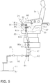
- FIG. 5 is a side view of the configuration inside the cab 5.
- a driver's seat 5a in which an operator sits is provided in the cab 5.
- a steering box 80 is disposed on the left side of the driver's seat 5a in the vehicle width direction.
- the joystick lever 24 is disposed so as to protrude obliquely upward from the steering box 80 toward the front.
- the connecting portion 25 connects the joystick lever 24 and the pilot valve 42.
- the connecting portion 25 mainly has a steering operation shaft 81, a connecting bar 82, and a universal joint 83.
- the steering operation shaft 81 is disposed vertically and is supported by the steering box 80 so as to be rotatable around its center axis E.
- the connecting bar 82 is disposed in the steering box 80 and connects the joystick lever 24 and the steering operation shaft 81.
- the steering operation shaft 81 is configured to connect a lever side shaft 81a, an input shaft 81b, and a valve side shaft 81c, in that order (see FIG. 8 (discussed below)). That is, one end of the lever side shaft 81a is connected to the connecting bar 82, and the other end of the lever side shaft 81a is connected to one end of the input shaft 81b. Also, the other end of the input shaft 81b is connected to one end of the valve side shaft 81c, and the other end of the valve side shaft 81c is connected to the universal joint 83. An assisting force or a counterforce from the force imparting component 27 (discussed below) is inputted to the input shaft 81b.
- the universal joint 83 connects the steering operation shaft 81 and the operation input shaft 61 of the pilot valve 42 disposed near the driver's seat 5a.
- the universal joint 83 has an extendible central portion 83a and joint portions 83b and 83c disposed at the ends of the central portion 83a.
- the joint portion 83b is connected to the steering operation shaft 81.
- the joint portion 83c is connected to the operation input shaft 61.
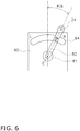
- FIG. 6 is a plan view of the area near the joystick lever 24 as viewed from above.
- the joystick lever 24 is formed so as to protrude obliquely upward from an arc-shaped hole 84 formed in the upper face of the steering box 80.
- the joystick lever 24 can turn horizontally around the steering operation shaft 81 (more precisely, the center axis E). Also, an R mark is made at the right edge of the hole 84 of the steering box 80, and an L mark is made at the left edge.
- the steering operation shaft 81 when the operator rotates the joystick lever 24 from the center position to the right by the rotation angle ⁇ in, the steering operation shaft 81 also rotates to the right by the rotation angle ⁇ in.
- This rotation of the steering operation shaft 81 by the rotation angle ⁇ in is transmitted through the universal joint 83 to the operation input shaft 61, and the operation input shaft 61 also rotates to the right by the rotation angle ⁇ in.
- the joystick lever 24 is rotated to the left.
- the link mechanism 26 has a follow-up lever 91, a follow-up link 92, and a bracket 93.
- the follow-up link 92 is fixed to the feedback input shaft 62 of the pilot valve 42.
- the bracket 93 is fixed to the front frame 11.
- the follow-up link 92 connects the follow-up lever 91 and the bracket 93.
- This link mechanism 26 links the front frame 11 to the pilot valve 42 disposed on the rear frame 12.
- the steering angle ⁇ s of the front frame 11 relative to the rear frame 12 is made to be the same as the rotation angle ⁇ fb of the feedback input shaft 62 by the link mechanism 26.
- the feedback input shaft 62 when the front frame 11 rotates to the right by the steering angle ⁇ s around the connecting shaft 13 with respect to the rear frame 12, the feedback input shaft 62 also rotates to the right by the rotation angle ⁇ s via the link mechanism 26, and when the front frame 11 rotates to the left by the angle ⁇ s, the feedback input shaft 62 also rotates to the left by the rotation angle ⁇ s via the link mechanism 26.
- FIG. 7a is a simplified diagram of the pilot valve 42.
- FIG. 7b is a graph of the relation between the vehicle body-lever deviation angle and the lever counterforce.
- FIG. 7c consists of cross sections along the C-C', D-D', E-E', and F-F' lines in FIG. 7a when the deviation angle ⁇ is zero.
- FIG. 7d consists of cross sections along the C-C', D-D', E-E', and F-F' lines in FIG.
- FIG. 7e consists of cross sections along the C-C', D-D', E-E', and F-F' lines in FIG. 7a when the when the deviation angle ⁇ is ⁇ 3.
- the cross sections along the C-C', D-D', E-E', and F-F' lines are all views from above.
- play in the joystick lever 24 is not taken into account in order to make the drawing easier to understand.
- the operation input shaft 61 When the operator rotates the joystick lever 24 from the center position by the rotation angle ⁇ in, the operation input shaft 61 also rotates by the rotation angle ⁇ in. On the other hand, since the response of the steering cylinders 21 and 22 is delayed, the steering angle ⁇ s gradually increases along with the rotation angle ⁇ in.
- This rotation angle ⁇ in of the joystick lever 24 indicates the target steering angle, and the steering angle ⁇ s indicates the actual steering angle.
- the feedback input shaft 62 also rotates at the same rotation angle ⁇ s as the steering angle ⁇ s in response to a change in the steering angle ⁇ s.
- the feedback spool 73 also rotates along with the feedback input shaft 62, and the feedback sleeve 74 connected via the second spring 65 also rotates as a result of this rotation.
- the operation sleeve 72 is also rotated by the rotation of the feedback sleeve 74.
- the difference in rotation angle that occurs between the rotation angle of the operation spool 71 and the rotation angle of the operation sleeve 72 corresponds to the deviation angle ⁇ (see FIG. 4b ).
- the joystick lever 24 Since the first spring 64 biases the operation spool 71 to the neutral position Np with respect to the operation sleeve 72, in order to increase the deviation angle ⁇ , the joystick lever 24 has to be operated against the biasing force of the first spring 64 .
- the first spring 64 has the spring characteristic S1 shown in FIG. 7b .
- the joystick lever 24 has to be operated with a force greater than or equal to the initial counterforce F1 (the force required to start bending the first spring 64).
- the lever counterforce increases as the deviation angle ⁇ increases. That is, as the deviation angle ⁇ increases, the force required to operate the joystick lever 24 increases.
- the first center pin 76 is disposed in the center of the slits 71a and 71b of the operation spool 71. Also, the second center pin 77 is disposed in the center of the slits 73a and 73b of the feedback spool 73.
- the deviation angle ⁇ is increased by turning the joystick lever 24 to the right, for example, and when the deviation angle ⁇ reaches the angle ⁇ 2, as shown in FIG. 7d , the first center pin 76 hits the wall portion 71ae formed in the circumferential direction of the slit 71a, and the wall portion 71be formed in the circumferential direction of the slit 71b.
- the second center pin 77 is disposed in the center of the slits 73a and 73b of the feedback spool 73.
- the initial counterforce (the force necessary to start bending the second spring 65) is set to F2 as indicated by the spring characteristic S2 of the second spring 65.
- the initial counterforce of the second spring 65 may be set higher than F2, as long as it is equal to or greater than F2.
- the second center pin 77 hits the wall portion 73ae formed in the circumferential direction of the slit 73a and the wall portion 73be formed in the circumferential direction of the slit 73b, as shown in FIG. 7e .
- the second center pin 77 can rotate by an angle of ( ⁇ 3 - ⁇ 2). That is, the pilot valve 42 is configured so that the deviation angle ⁇ can not be greater than the angle ⁇ 3. Therefore, as shown in FIG. 7b , the lever counterforce rises linearly at the angle ⁇ 3. If the second center pin 77 hits the wall portions 73ae and 73be hard, it produces a sudden reaction that subjects the wrist of the operator to a load. This angle ⁇ 3 is also called a catch-up angle.
- FIG. 7b illustrates an example in which the joystick lever 24 is rotated to the right, but the same holds true when the joystick lever 24 is rotated to the left, in which case the deviation angle ⁇ is a negative value, and is in right and left symmetry as indicated by the two-dot chain line L7 in FIG. 10b (discussed below). That is, the first center pin 76 hits the wall portions 71ae and 71be at - ⁇ 2, and the second center pin 77 hits the wall portions 71ae and 71be at - ⁇ 3.
- the pilot valve 42 is configured so that the absolute value of the deviation angle ⁇ does not become greater than the angle ⁇ 3.
- a difference is generated between the rotation angle of the operation spool 71 and the rotation angle of the operation sleeve 72 up until the deviation angle ⁇ reaches ⁇ 2, but once the difference exceeds the angle ⁇ 2, there is no longer any difference between the operation spool 71 and the operation sleeve 72, so the aperture of the pilot valve 42 is constant.
- the deviation angle ⁇ is constant while the deviation angle ⁇ between the angles ⁇ 2 and ⁇ 3, but the pilot pressure may be varied according to the deviation angle by controlling the variable pressure reducer 41.
- FIG. 8 is an oblique view of the force imparting component 27.
- the force imparting component 27 imparts an assisting force or a counterforce to the operation of the joystick lever 24.
- the force imparting component 27 has an electric motor 111 and a worm gear 112.
- the worm gear 112 has a cylindrical worm 112a and a worm wheel 112b.
- the worm wheel 112b is provided around the input shaft 81b described above, and meshes with the cylindrical worm 112a.
- the output shaft of the electric motor 111 is connected to the cylindrical worm 112a, and rotates the cylindrical worm 112a around its center axis.
- the electric motor 111 is driven on the basis of a command from a drive circuit 204 provided to the controller 28.
- a first end 81b1 of the input shaft 81b is connected to the lever side shaft 81a, and the second end 81b2 is connected to the valve side shaft 81c.
- a force is applied to the input shaft 81b in the clockwise direction, thereby imparting an assisting force to the operation of the joystick lever 24.
- a counterforce is applied to the operation of the joystick lever 24 by applying a force to the input shaft 81b in the counterclockwise direction.
- a torque sensor 103 is provided to the input shaft 81b.
- the torque sensor 103 senses torque generated at the input shaft 81b when the operator applies force to the joystick lever 24.
- the torque sensor 103 in this embodiment senses the rotation direction of the input shaft 81b and the torque generated at the input shaft 81b by using a coil to sense twisting of the torsion bar, for example.
- the sensed rotation direction and torque T are outputted to the controller 28 as a steering torque signal.
- FIG. 9 is a block diagram of the configuration of the controller 28.
- the controller 28 comprises a storage component 200, a first assist torque determination component 201, a second assist torque determination component 202, a calculator 203, and the drive circuit 204.
- the first assist torque determination component 201, the second assist torque determination component 202, and the calculator 203 are executed by a computing device such as a CPU.
- the storage component 200 stores the relation of the applied assist torque to the lever input torque (first assist torque information) for each speed. Also, the storage component 200 stores the relation of the applied assist torque to the deviation angle ⁇ (second assist torque information).
- the first assist torque information and the second assist torque information are preset. The first assist torque information and the second assist torque information will be described in detail below.
- the storage component 200 may be provided inside the controller 28 or outside the controller 28. Also, the storage component 200 is constituted by a RAM, a ROM, a hard disk drive, or the like.
- the first assist torque determination component 201 receives a steering torque signal (S(T0) in FIG. 9 ) from the torque sensor 103 and a speed signal (S(V) in FIG. 9 ) from a vehicle speed sensor 105. The first assist torque determination component 201 then determines the first assist torque from the steering torque signal from the torque sensor 103 and the speed signal from the vehicle speed sensor 105, on the basis of the first assist torque information stored in the storage component 200. The first assist torque determination component 201 outputs the determined first assist torque as a first assist torque signal (S(T1) in FIG. 9 ).
- the second assist torque determination component 202 then calculates the difference between the rotation angle ⁇ in and the rotation angle ⁇ fb, and calculates the deviation angle ⁇ ( ⁇ in - ⁇ fb).
- the second assist torque determination component 202 determines the second assist torque from the deviation angle ⁇ on the basis of the second assist torque information stored in the storage component 200.
- the second assist torque information is set so as to generate resistance against operation so that when the joystick lever 24 is operated, the operator will intuitively grasp the timing at which the inclination operation (articulation) of the front frame 11 with respect to the rear frame 12 starts.
- the second assist torque determination component 202 outputs the determined second assist torque as a second assist torque signal (S(T2) in FIG. 9 ).
- the calculator 203 calculates the sum of the first assist torque determined by the first assist torque determination component 201 and the second assist torque determined by the second assist torque determination component 202, and calculates the target assist torque to be imparted to the input shaft component 81b.
- the calculator 203 outputs the calculated target assist torque to the drive circuit 204 as a target assist torque signal (S(T3) in FIG. 9 ).
- the drive circuit 204 drives the electric motor 111 on the basis of the calculated target assist torque.
- the controller 28 can impart an assisting force or a counterforce to the operation of the joystick lever 24 by the operator on the basis of the torque T, the deviation angle ⁇ , and the speed V.
- control of the electric motor 111 and the variable pressure reducer 41 by the controller 28 may be performed by wire or wirelessly.
- the timing sensor 29 senses the timing at which resistance against the operation of the joystick lever 24 is generated in order to allow the operator to feel the start timing of the articulation.
- the timing sensor 29 has the first rotation angle sensor 101 and the second rotation angle sensor 102 described above.
- the first rotation angle sensor 101 is provided to the operation input shaft 61, and senses the rotation angle ⁇ in of the operation input shaft 61.
- the operation input shaft 61 When the joystick lever 24 is in its center position, the operation input shaft 61 is in a specific initial position, and the rotation angle ⁇ in of the operation input shaft 61 is zero. Since the steering angle ⁇ s is also zero, the feedback input shaft 62 is also in a specific initial position. In this embodiment, as shown in FIG. 7a , if zero is a state of going along the longitudinal direction with respect to the rear frame 12, then the steering angle ⁇ s is the angle from that state. Also, as shown in FIG. 6 , the rotation angle ⁇ in indicates the rotation angle from the center position of the joystick lever 24. In finding the deviation angle, rotation to the right may be calculated as a positive angle and rotation to the left may be calculated as a negative angle, for example.
- the operation spool 71 is in the neutral position Np shown in FIG. 4a with respect to the operation sleeve 72.
- the operator applies the operation force Fin in order to rotate the joystick lever 24 from the center position to the right side as shown in FIG. 6 .
- the operation force Fin exceeds F1 of the first spring 64
- the operation input shaft 61 rotates to the right just like the joystick lever 24, and the rotation angle ⁇ in of the operation input shaft 61 increases.
- the operation spool 71 rotates to the right with respect to the operation sleeve 72 along with the rotation of the operation input shaft 61.
- the operation sleeve 72 is integrated with the feedback sleeve 74, and the feedback sleeve 74 is linked to the feedback spool 73 by the second spring 65.
- the initial counterforce F2 of the second spring 65 is equal to or greater than the counterforce of the spring characteristic S1 of the first spring 64 shown in FIG. 7b . Therefore, the operation sleeve 72 does not rotate along with the operation spool 71, and the operation spool 71 rotates to the right with respect to the operation sleeve 72.
- the operation spool 71 rotates to the right with respect to the operation sleeve 72 and moves to the right pilot position Rp, pilot pressure is supplied to the second pilot port P8, and pilot pressure is supplied to the second pilot chamber 35.
- valve body 33 of the steering valve 32 moves to the right steering position Rs, fluid is supplied to the extension port 21a of the steering cylinder 21 and the contraction port 22b of the steering cylinder 22, and fluid is discharged from the contraction port 21b of the steering cylinder 21 and the extension port 22a of the steering cylinder 22. Consequently, articulation commences, the steering angle ⁇ s gradually increases, and the front frame 11 is pointed to the right with respect to the rear frame 12 (see R in FIG. 2 ). This change in the steering angle ⁇ s is transmitted by the link mechanism 26 to the feedback input shaft 62, and the feedback input shaft 62 rotates at the rotation angle ⁇ s.
- the operation input shaft 61 When the operator stops the joystick lever 24 at a specific rotation angle ⁇ 1, the operation input shaft 61 also stops at the rotation angle ⁇ 1.
- the rotation angle ⁇ s of the feedback input shaft 62 also increases.
- the feedback spool 73 rotates along with the feedback input shaft 62, and the feedback sleeve 74 linked to the feedback spool 73 via the second spring 65 also rotates. Since the feedback sleeve 74 is integrated with the operation sleeve 72 via the first center pin 76, the second center pin 77, and the drive shaft 75, the operation sleeve 72 also rotates along with the rotation of the feedback sleeve 74.
- the difference in the rotation angle between the operation sleeve 72 and the operation spool 71 decreases as the operation sleeve 72 rotates.
- the deviation angle ⁇ drops to zero.
- the operation spool 71 of the pilot valve 42 is in the neutral position Np with respect to the operation sleeve 72.
- the pilot pressure is the same in the first pilot chamber 34 and the second pilot chamber 35 of the steering valve 32, and the steering valve 32 is also in the neutral position Ns. Accordingly, fluid is neither supplied nor discharged to the left and right steering cylinders 21 and 22, and the steering angle ⁇ s is maintained at the rotation angle ⁇ 1.
- the valve body 33 of the steering valve 32 moves to the left steering position Ls, fluid is supplied to the contraction port 21b of the steering cylinder 21 and the extension port 22a of the steering cylinder 22, and fluid is discharged from the extension port 21a of the steering cylinder 21 and the contraction port 22b of the steering cylinder 22.
- the steering angle ⁇ s therefore gradually decreases from the rotation angle ⁇ 1.
- This change in the steering angle ⁇ s is transmitted by the link mechanism 26 to the feedback input shaft 62, and the feedback input shaft 62 rotates at the same change in the rotation angle as the change in the steering angle ⁇ s.
- the pilot pressure is the same in the first pilot chamber 34 and the second pilot chamber 35 of the steering valve 32, and the steering valve 32 is also in the neutral position Ns. Consequently, fluid is neither supplied to nor discharged from the left and right steering cylinders 21 and 22, and the steering angle ⁇ s also returns to zero and held there. As a result, the front frame 11 is returned to an orientation along the longitudinal direction with respect to the rear frame 12.
- the wheel loader 1 in this embodiment changes the assist torque to be imparted to the operation of the joystick lever 24 according to the torque and the speed on the basis of the first assist torque information.
- the wheel loader 1 in this embodiment is set to generate resistance against operation so that when the joystick lever 24 is operated, the operator will intuitively grasp the timing at which an inclination operation (articulation) of the front frame 11 with respect to the rear frame 12 starts, on the basis of the second assist torque information.
- the first assist torque information and the second assist torque information will be described.
- FIG. 10a is a graph of the assist torque (first assist torque information) imparted for each speed versus the input torque.
- the solid line L1 indicates assist torque information at a vehicle speed of 0 km/h
- the dotted line L2 indicates assist torque information at a vehicle speed of 25 km/h
- the one-dot chain line L3 indicates assist torque information at a vehicle speed of 40 km/h.
- positive lever input torque indicates the torque generated by rotation of the joystick lever 24 toward the right side
- negative lever input torque indicates rotation of the joystick lever 24 toward the left side.
- positive assist torque applies a force to clockwise rotation of the input shaft 81b
- negative assist torque applies a force to the counterclockwise rotation of the input shaft 81b.
- L1a indicates the assist torque when the joystick lever 24 is rotated to the right at a vehicle speed of 0 km/h
- L1b indicates the assist torque when the joystick lever 24 is rotated to the left at a vehicle speed of 0 km/h
- L2a indicates the assist torque when the joystick lever 24 is rotated to the right at a vehicle speed of 25 km/h
- L2b indicates the assist torque when the joystick lever 24 is rotated to the left at a vehicle speed of 25 km/h
- L3a indicates the assist torque when the joystick lever 24 is rotated to the right at a vehicle speed of 40 km/h
- L3b indicates the assist torque when the joystick lever 24 is rotated to the left at a vehicle speed of 40 km/h.
- L1a, L2a, and L3a show a case in which the joystick lever 24 is rotated to the right side, and since the assist torque is a positive value at this point, a force is applied to the clockwise rotation of the input shaft 81b.
- L1b, L2b, and L3b show a case in which the joystick lever 24 is rotated to the left side, and since the assist torque is a negative value, a force is applied to the counterclockwise rotation of the input shaft 81b.
- an assist force is added to the operation of the joystick lever 24.
- L1a and L1b are symmetrical with respect to the origin
- L2a and L2b are symmetrical with respect to the origin
- L3a and L3b are symmetrical with respect to the origin. Therefore, the assist force is in right and left symmetry with respect to the absolute value of the input torque.
- FIG. 10b is a graph of lever counterforce versus the vehicle body-lever deviation angle when assist torque is and is not imparted.
- a positive deviation angle ⁇ indicates that the joystick lever 24 has moved to the right side
- a negative deviation angle ⁇ indicates that the joystick lever 24 has moved to the left side. That is, as shown in FIG. 7e , the angle ⁇ 3 indicates the angle at which the operation is restricted when the joystick lever 24 has been rotated to the right, and the angle - ⁇ 3 indicates the angle at which the operation is restricted when the joystick lever 24 has been rotated to the left. As shown in FIG.
- the angle ⁇ 2 indicates the angle at which the first center pin 76 hits the wall portions 71ae and 71be when the joystick lever 24 has been rotated to the right
- the angle - ⁇ 2 indicates the angle at which the first center pin 76 hits the wall portions 71 ae and 71be when the joystick lever 24 has been rotated to the left.
- the solid line L4 shows the lever counterforce with respect to the deviation angle when the vehicle speed is 0 km/h
- the dotted line L5 shows the lever counterforce with respect to the deviation angle when the vehicle speed is 25 km/h
- the one-dot chain line L6 shows the lever counterforce with respect to the deviation angle when the vehicle speed is vehicle speed is 40 km/h.
- the two-dot chain line L7 shows the case when no assist torque is imparted.
- FIG. 10b shows the same state as FIG. 7b .
- L4 to L7 are in line symmetry with respect to the vertical axis, and in L4 to L6, an assist force is imparted symmetrically to left and right operations, and the lever counterforce is smaller than when no assist torque is imparted (L7).
- lever counterforce is set to increase as the speed rises. This makes it possible to achieve both good operability at low speed and good stability at high speed.
- the first assist torque determination component 201 determines the first assist torque from the assist torque information for three stored vehicle speeds on the basis of the sensed value from the vehicle speed sensor 105. When the sensed value from the vehicle speed sensor 105 is within these three speeds (for example, 12 km/h), assist torque for that vehicle speed is calculated by interpolation. Calculating the first assist torque by interpolation allows the assist torque to be continuously varied according to changes in speed.
- the second assist torque information indicates the assist torque to be imparted in order to generate resistance to the operation of the joystick lever 24 before articulation begins when the joystick lever 24 is operated.
- FIG. 11a is a graph of assist torque versus vehicle body-lever deviation angle ( ⁇ ) (second assist torque information).
- FIG. 11a also shows the case when the joystick lever 24 is operated to the right side at a positive vehicle body-lever deviation angle ⁇ ( ⁇ in - ⁇ s), when the joystick lever 24 is operated to the left side at a negative vehicle body-lever deviation angle ⁇ . Also shows are the case when positive assist torque applies a force to the clockwise rotation of the input shaft 81b, and when negative assist torque applies a force to the counterclockwise rotation of the input shaft 81b.
- a counterforce is generated when the deviation angle ⁇ reaches an angle of ⁇ 4, and the assist torque is set so that the counterforce increases until the deviation angle reaches ⁇ 5.
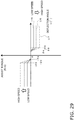
- FIG. 11b is a graph of lever counterforce versus the vehicle body-lever deviation angle when assist torque is and is not imparted, on the basis of the second assist torque information in FIG. 11a .
- the solid line L8 indicates the case when assist torque is imparted, and the two-dot chain line L9 indicates the case when assist torque is not imparted.
- L9 is the same graph as in FIG. 7b and L7 in FIG. 10b .
- the one-dot chain line L10 shows a graph of the opening surface area of the steering valve 32 with respect to the deviation angle ⁇ .
- the vertical axis is the opening surface area.
- the opening area of the steering valve 32 also increases, the deviation angle reaches its maximum value in the vicinity of ⁇ 2, and even if the absolute value of the deviation angle increases after that, the opening area remains constant. Also, the timing at which the articulation begins is delayed somewhat from ⁇ 6, which is the opening timing of the steering valve 32, and is indicated by ⁇ 7. - ⁇ 7 to + ⁇ 7 correspond to the angle of play in the joystick lever 24.
- the angle ⁇ 4 is set to a value less than the angle ⁇ 2 shown in FIGS. 7b and 10b , and the angle - ⁇ 4 to a value greater than - ⁇ 2.
- the opening angle + ⁇ 6 is set between + ⁇ 4 and + ⁇ 5, and the opening angle - ⁇ 6 is set between - ⁇ 5 and - ⁇ 4. Also, since the start of the articulation is delayed from the start of the opening of the steering valve 32, resistance against the operation of the joystick lever 24 is generated before the start of the articulation.
- the slope from the neutral position to the deviation angle ⁇ 4 (the increase in lever counterforce with respect to the deviation angle ⁇ ) is due to the elastic force of the first spring 64.
- the slope from + ⁇ 4 to + ⁇ 5 is due to the increase in resistance produced by the second assist torque shown in FIG. 11a and to the elastic force of the first spring 64, and the proportional increase of the lever counterforce versus the deviation angle is greater than between the neutral position (where the deviation angle ⁇ is zero) and + ⁇ 4.
- the slope of L8 when the deviation angle ⁇ is from + ⁇ 5 to + ⁇ 2 is due to the elastic force of the first spring 64.
- the slope of L8 when the deviation angle ⁇ is from + ⁇ 2 to + ⁇ 3 is due to the elastic force of the second spring 65.
- the negative side of L8 is symmetrical with the positive side.
- FIG. 12 is a flowchart of the control operation of the force imparting component 27.
- the first assist torque determination component 201 of the controller 28 receives a steering torque signal (S(T0) in FIG. 9 ) from the torque sensor 103.
- the steering torque signal includes information related to the amount of torque and the direction of rotation. For example, if the torque value is positive, the torque is considered to be produced by clockwise rotation of the input shaft 81b, and if the torque value is negative, the torque is considered to be produced by counterclockwise rotation of the input shaft 81b, and therefore information related to the amount of torque and the rotation direction can be included in the torque value.
- step S130 the controller 28 determines the steering direction of the joystick lever 24 on the basis of the steering torque signal. This steering direction determines the rotational direction of the electric motor 111 when force is imparted.
- step S140 the first assist torque determination component 201 of the controller 28 acquires a signal of the vehicle speed V (S(V) in FIG. 9 ) from the vehicle speed sensor 105.
- step S150 the first assist torque determination component 201 determines the first assist torque on the basis of the first assist information stored in the storage component 200.
- the first assist torque determination component 201 then outputs the first assist torque thus determined as a first assist torque signal (S(T1) in FIG. 9 ).
- the controller 28 stores the three kinds of first assist torque information shown in FIG. 10 (when the vehicle speed is 0 km/h, 25 km/h, and 40 km/h). When the sensed value from the vehicle speed sensor 105 is within these three speeds (for example, 12 km/h), the controller 28 calculates the assist torque at that speed by interpolation. The controller 28 thus determines the first assist torque by interpolation. Calculating the first assist torque by interpolation allows the assist torque to be continuously varied according to changes in speed.
- step S160 the second assist torque determination component 202 determines the second assist torque on the basis of the second assist torque information shown in FIG. 11a from the deviation angle ⁇ calculated in step S110.
- the second assist torque determination component 202 then outputs the second assist torque thus determined as a second assist torque signal (S(T2) in FIG. 9 ).
- step S170 the calculator 203 adds the first assist torque to the second assist torque to calculate the target assist torque, and outputs the calculated target assist torque as a target assist torque signal (S(T3)) to the drive circuit 204.
- S(T3) target assist torque signal
- the target assist torque is a positive or negative value, and also includes information about the rotational direction. For example, if the rotation is to the right, an assisting force is imparted with the first assist torque information shown in FIG. 10a , but with the second assist torque information shown in FIG. 11a , if the deviation angle ⁇ exceeds the angle ⁇ 4, counterforce is imparted.
- these values are summed, and when the absolute value of the counterforce is greater than the absolute value of the assisting force, the target assist torque is a negative value, and a force equal to the remainder of subtracting the absolute value of the assisting force from the absolute value of the counterforce is imparted to counterclockwise rotation.
- the target assist torque is a positive value, and a force equal to the remainder of subtracting the absolute value of the counterforce from the absolute value of the assisting force is imparted.
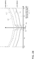
- FIG. 13 is a graph of the lever counterforce versus the deviation angle when the assist torque combined by the calculator 203 is imparted to the operation of the joystick lever 24.
- three kinds of combined assist torque are shown as examples: high speed, medium speed, and low speed.
- the solid line L11 indicates the lever counterforce versus the deviation angle when the vehicle speed is 0 km/h
- the dotted line L12 indicates the lever counterforce versus the deviation angle when the vehicle speed is 25 km/h
- the one-dot chain line L13 indicates the lever counterforce versus the deviation angle when the vehicle speed is 40 km/h.
- the two-dot chain line L14 indicates the case when no assist torque is imparted.
- L14 is the same graph as L9 and L7.
- the lever counterforce is set to increase as the speed rises. This makes it possible to achieve both good operability at low speed and good stability at high speed. Also, since the rate of increase (slope) of the lever counterforce versus the deviation angle is steep between the absolute values of ⁇ 4 and ⁇ 5 of the deviation angle for each speed (solid line L11, dotted line L12, one-dot chain line L13), the operator can feel the beginning of the articulation.
- the high-speed graph (one-dot chain line L13) intersects with the graph when no assist torque is imparted (the two-dot chain line L14) at the angle ⁇ 8 between the absolute values of ⁇ 4 to ⁇ 5 of the deviation angle.
- the assisting force imparted by the first assist torque information is small at high speed, so the counterforce is increased by imparting counterforce according to the second assist torque information, as compared to when no assist torque is imparted. That is, a counterforce is imparted to the operation of the joystick lever 24 in the region where the absolute value of the deviation angle is greater than the intersecting angle ⁇ 8.
- resistance is generated in the joystick lever 24 by weakening the assisting force when the deviation angle is between ⁇ 4 and ⁇ 8 and between - ⁇ 4 and - ⁇ 8, with respect to when no assisting force is imparted (see the two-dot chain line L14). Resistance is then generated in the joystick lever 24 by increasing the counterforce when the deviation angle is between ⁇ 8 and ⁇ 5, and between - ⁇ 5 and - ⁇ 8.
- step S180 the calculator 203 outputs a command torque signal to the drive circuit 204 on the basis of the target assist torque that has been determined. Consequently, the electric motor 111 is driven, and a force is imparted to the operation of the joystick lever 24 via the connecting portion 25.
- the timing at which resistance to the operation of the joystick lever 24 is generated is determined on the basis of the deviation angle ⁇ , but in Embodiment 2, the timing of at which the resistance is generated is determined by sensing the position of the valve body 33 of the steering valve 32.
- Embodiment 2 we will focus on what is different from the configuration in Embodiment 1. Those components that are the same as in Embodiment 1 will be numbered the same and will not be described again.
- FIG. 14 is a diagram of a steering operation device 308 of the wheel loader 1 Embodiment 2. As shown in FIG. 14 , the steering operation device 308 in Embodiment 2 is different from the steering operation device 8 in Embodiment 1 in that it has a valve body position sensor 309 that senses the position of the valve body 33 of the steering valve 32. A controller 328 receives the sensed value from the valve body position sensor 309.
- FIG. 15 is a block diagram of the configuration of the controller 328 in Embodiment 2. Unlike the controller 28 in Embodiment 1, the controller 328 has a second assist torque determination component 302.
- the second assist torque determination component 302 receives a valve body position signal (S(Vp) in FIG. 15 ) related to the valve body position sensed by the valve body position sensor 309.
- the second assist torque determination component 302 determines the second assist torque from the valve body position on the basis of the second assist torque information stored in the storage component 200, and sets the second assist torque thus determined as the second assist torque (S(T2) in FIG. 15 ).
- FIG. 16 is a diagram of the second assist torque information in Embodiment 2.
- a state in which the valve body 33 of the steering valve 32 is in the neutral position Ns is defined as 0, a state in which the valve body 33 has moved to the right steering position Rs side is on the positive side of the horizontal axis, and a state in which the valve body 33 has moved to the left steering position Ls side is on the negative side of the horizontal axis.
- the diagram shows a case in which a positive assist torque applies a force to the input shaft 81b in the clockwise rotation direction, and a case in which a negative assist torque applies a force to the input shaft 81b in the counterclockwise rotation direction.
- These positions ⁇ P1 and ⁇ P2 are set on the basis of the opening timing of the steering valve 32 or the start timing of the articulation.
- the opening position of the steering valve 32 is indicated by the position ⁇ P3.
- the position P1 and position P2 are preset to include the position P3 in between them.
- the position -P1 and position -P2 are preset to include the position -P3 in between them.
- the position of the valve body 33 when articulation begins is indicated by P4.
- the position P4 is somewhat larger than the position P3, and the position -P4 is somewhat smaller than the position -P3.
- the position P4 is smaller than the position P2, and the position -P4 is larger than the position -P2, but depending on the rise (slope) of the assist torque, the position P4 may be larger than the position P2, and the position -P4 may be smaller than the position -P2.
- FIG. 17 is a flowchart of the operation for controlling the force imparting component.
- step S210 the controller 328 receives a valve body position signal (S(Vp) in FIG. 15 ) from the valve body position sensor 309, and acquires information about the position of the valve body 33.
- a valve body position signal S(Vp) in FIG. 15
- step S120 the first assist torque determination component 201 of the controller 328 receives a steering torque signal from the torque sensor 103.
- the steering torque signal includes information related to the amount of torque and the rotation direction.
- step S130 the controller 328 determines the steering direction of the joystick lever 24 on the basis of the steering torque signal. This steering direction determines the rotation direction of the electric motor 111 when the force is imparted.
- step S140 the first assist torque determination component 201 of the controller 328 acquires a signal indicating the vehicle speed V (S(V) in FIG. 15 ) from the vehicle speed sensor 105.
- step S150 the first assist torque determination component 201 determines the first assist torque on the basis of the first assist information stored in the storage component 200.
- the first assist torque determination component 201 then outputs the first assist torque thus determined as a first assist torque signal (S(T1) in FIG. 15 ).
- step S260 the second assist torque determination component 302 determines the second assist torque on the basis of the second assist torque information shown in FIG. 16 from the valve body position calculated in step S210.
- the second assist torque determination component 202 then outputs the second assist torque thus determined as a second assist torque signal (S(T2) in FIG. 15 ).
- step S170 the calculator 203 calculates the target assist torque by adding the first assist torque to the second assist torque, and outputs the calculated target assist torque as a target assist torque signal (S(T3) in FIG. 15 ) to the drive circuit 204.
- Embodiment 2 the timing at which resistance against the operation of the joystick lever 24 is generated is determined by sensing the position of the valve body 33 of the steering valve 32, but in Embodiment 3, the timing at which resistance is generated is determined by sensing the pilot pressure.
- Embodiment 3 we will focus on what is different from the configuration in Embodiment 2. Those components that are the same as in Embodiment 2 will be numbered the same and will not be described again.
- FIG. 18 is a view of the steering operation device 408 of the wheel loader 1 in Embodiment 3.
- the steering operation device 408 in Embodiment 3 differs from the steering operation device 308 in Embodiment 2 in that the valve body position sensor 309 is not provided, and there are pilot pressure sensors 409a and 409b for sensing the pilot pressure.
- the pilot pressure sensor 409a is provided to the first pilot line 46 and senses the pilot pressure supplied from the pilot hydraulic pressure source 43 to the first pilot line 46 via the pilot valve 42.
- the pilot pressure sensor 409b is provided to the second pilot line 47 and senses the pilot pressure supplied from the pilot hydraulic pressure source 43 to the second pilot line 47 via the pilot valve 42.
- the controller 428 receives the sensed values from the pilot pressure sensors 409a and 409b.
- FIG. 19 is a block diagram of the configuration of the controller 428 in Embodiment 3. Unlike the controller 328 in Embodiment 2, the controller 428 has a second assist torque determination component 402.
- the second assist torque determination component 402 receives pilot pressure signals (S(Ppa) and S(Ppb) in FIG. 19 ) related to the values sensed by the pilot pressure sensors 409a and 409b.
- the second assist torque determination component 402 finds the differential pressure from the values sensed by the pilot pressure sensors 409a and 409b, and determines the second assist torque from the differential pressure on the basis of the second assist torque information stored in the storage component 200.
- the second assist torque determination component 402 then outputs the second assist torque thus determined as a second assist torque signal (S(T2) in FIG. 19 ).
- the first assist torque and the determined second assist torque are added together by the calculator 203 to calculate the assist torque.
- FIG. 20 is a diagram showing second assist torque information in Embodiment 3.
- FIG. 20 shows the case when positive assist torque applies a clockwise force to the input shaft 81b, and when negative assist torque applies a counterclockwise force to the input shaft 81b.
- a state in which there is no difference between the hydraulic pressure of the first pilot line 46 and the hydraulic pressure of the second pilot line 47 is set as zero.
- the positive size of the horizontal axis is when the hydraulic pressure of the second pilot line 47 is higher than the hydraulic pressure of the first pilot line 46
- the negative size of the horizontal axis is when the hydraulic pressure of the second pilot line 47 is lower than the hydraulic pressure of the first pilot line 46.
- the differential pressure ⁇ Q1 and the differential pressure ⁇ Q2 are set on the basis of the timing at which the steering valve 32 opens or the timing at which articulation starts.
- the differential pressure when the steering valve 32 opens is indicated by ⁇ Q3.
- the differential pressure Q1 and the position Q2 are preset so as to include a differential pressure Q3 in between them.
- the differential pressure -Q1 and the differential pressure -Q2 are preset so as to include a differential pressure -Q3 in between them.
- the differential pressure at the point when articulation starts is indicated by ⁇ Q4.
- the differential pressure Q4 is somewhat greater than the differential pressure Q3, and the differential pressure -Q4 is somewhat less than the differential pressure -Q3.
- the differential pressure Q4 is less than the differential pressure Q2, and the differential pressure -Q4 is greater than the differential pressure -Q2, but depending on the rise (slope) of the assist torque, the differential pressure Q4 may be greater than the differential pressure Q2, and the differential pressure -Q4 may be less than the differential pressure -Q2.
- FIG. 21 is a flowchart of the operation of controlling the force imparting component.
- step S310 the controller 428 receives pilot pressure signals (S(Ppa) and S(Ppb) in FIG. 19 ) from the pilot pressure sensors 409a and 409b, and reads the values sensed by the pilot pressure sensors 409a and 409b.
- pilot pressure signals S(Ppa) and S(Ppb) in FIG. 19
- step S360 the second assist torque determination component 402 calculates the differential pressure by subtracting the hydraulic pressure of the first pilot line 46 from the hydraulic pressure of the second pilot line 47, and calculates the second assist torque from the second assist torque information stored in the storage component 200 (see FIG. 20 ).
- the second assist torque determination component 402 then outputs the determined second assist torque as a second assist torque signal (S(T2) in FIG. 19 ).
- step S170 the calculator 203 calculates the target assist torque by adding the first assist torque to the second assist torque, and in step S180 a command torque signal (S(T3) in FIG. 19 ) is outputted to the drive circuit 204.
- Embodiment 3 when the absolute value of the differential pressure obtained by subtracting the hydraulic pressure of the first pilot line 46 from the hydraulic pressure of the second pilot line 47 reaches Q1, the force imparting component 27 is controlled so that resistance to the operation of the joystick lever 24 is generated.
- Embodiment 2 the timing at which resistance to the operation of the joystick lever 24 is generated is determined by sensing the position of the valve body 33 of the steering valve 32, but in Embodiment 4, the timing at which the resistance is generated is determined by sensing the load pressure of the pump of the hydraulic pressure source 31.
- Embodiment 4 we will focus on the differences from the configuration of Embodiment 2. Those components that are the same as in Embodiment 2 will be numbered the same and will not be described again.
- FIG. 22 is a diagram of a steering operation device 508 of the wheel loader 1 in Embodiment 4.
- the steering operation device 508 in Embodiment 4 differs from the steering operation device 308 in Embodiment 2 in that it does not have the valve body position sensor 309, and instead has a pump load pressure sensor 509.
- the pump load pressure sensor 509 is provided to the main hydraulic line 36 and senses the load pressure on the main hydraulic pressure source 31 by sensing the pressure of the main hydraulic line 36.
- a controller 528 receives the value sensed by the pump load pressure sensor 509.
- FIG. 23 is a block diagram of the configuration of the controller 528 in Embodiment 4. Unlike the controller 328 in Embodiment 2, the controller 528 has a second assist torque determination component 502.
- the second assist torque determination component 502 receives a pump load pressure signal (S(Pp) in FIG. 23 ) related to the value sensed by the pump load pressure sensor 509.
- the second assist torque determination component 502 determines the second assist torque from the sensed value on the basis of the second assist torque information stored in the storage component 200, and outputs the second assist torque thus determined as a second assist torque signal (S(T2) in FIG. 23 ).
- FIGS. 24a and 24b are graphs of the second assist torque information in Embodiment 4.
- FIG. 24a shows the second assist torque information that is used when the torque sensor 103 has sensed that the joystick lever 24 has moved to the right side.
- FIG. 24b shows the second assist torque information used when the torque sensor 103 senses that the joystick lever 24 is moved to the left.
- the second assist torque determination component 502 senses the operation direction of the joystick lever 24 on the basis of the value sensed by the torque sensor 103, and applies the second assist torque information shown in FIG. 24a .
- the second assist torque information shown in FIG. 24a when the pump load pressure produced by the main hydraulic pressure source 31 reaches R1, a force is applied to the input shaft 81b in the counterclockwise rotation direction. The force in the counterclockwise rotation direction then increases (resistance increases) at a constant slope until the pump load pressure reaches R2. Once the pump load pressure reaches R2, the force applied to the input shaft 81b in the counterclockwise rotation direction remains constant.
- the second assist torque determination component 502 senses the operation direction of the joystick lever 24 on the basis of the value sensed by the torque sensor 103, and applies the second assist torque information shown in FIG. 24b .
- the second assist torque information shown in FIG. 24b when the joystick lever 24 is rotated to the left and the load pressure reaches R1, a force is applied to the input shaft 81b in the clockwise rotation direction. The force in the clockwise direction then increases (resistance increases) at a constant slope until the load pressure reaches R2. Once the load pressure reaches - R2, the force in the clockwise direction applied to the input shaft 81b remains constant.
- load pressures R1 and R2 are set on the basis of the timing at which the steering valve 32 opens or the timing at which the articulation starts. With the second assist torque information shown in FIGS. 24a and 24b , the load pressure when the steering valve 32 opens is indicated by R3.
- the load pressure R1 and the load pressure R2 are preset so as to include the load pressure R3 in between them.
- the load pressure when the articulation starts is indicated by R4.
- the load pressure R4 is greater than the load pressure R3.
- the load pressure R4 is less than the load pressure R2, but depending on the rise (slope) of the assist torque, the load pressure R4 may be greater than the load pressure R2, and the load pressure -R4 may be less than the load pressure -R2.
- FIG. 25 is a flowchart of the operation of controlling the force imparting component.
- step S410 the controller 428 receives a pump load pressure signal (S(Pp) in FIG. 23 ) from the pump load pressure sensor 509, and reads the value sensed by the pump load pressure sensor 509.
- S(Pp) pump load pressure signal
- Steps S120 to S150 are the same as in Embodiment 2.
- step S460 the second assist torque determination component 402 senses the operation direction of the joystick lever 24 from the value sensed by the torque sensor 103, and applies one of the two kinds of second assist information stored in the storage component 200 (see
- the second assist torque determination component 402 then calculates the second assist torque from the applied second assist torque information on the basis of the value sensed by the pump load pressure sensor 509. Next, the second assist torque determination component 402 outputs the second assist torque thus determined as a second assist torque signal (S(T2) in FIG. 23 ).
- step S170 the calculator 203 calculates the target assist torque by adding the first assist torque to the second assist torque, and in step S180 outputs a command torque signal (S(T3) in FIG. 23 ) to the drive circuit 204.
- Embodiment 4 when the load pressure of the main hydraulic pressure source 31 reaches R1, this triggers the control of the force imparting component 27 so as to produce resistance to the operation of the joystick lever 24.
- the work vehicle and work vehicle control method of the present invention have the effect of facilitating fine operations, and are useful in a wheel loader or the like.
Landscapes
- Engineering & Computer Science (AREA)
- Chemical & Material Sciences (AREA)
- Mechanical Engineering (AREA)
- Transportation (AREA)
- Combustion & Propulsion (AREA)
- General Engineering & Computer Science (AREA)
- Structural Engineering (AREA)
- Civil Engineering (AREA)
- Mining & Mineral Resources (AREA)
- Physics & Mathematics (AREA)
- General Physics & Mathematics (AREA)
- Steering Control In Accordance With Driving Conditions (AREA)
- Power Steering Mechanism (AREA)
- Operation Control Of Excavators (AREA)
- Steering Controls (AREA)
Abstract
Description
- The present invention relates to a work vehicle and to a method for controlling a work vehicle.
- As an articulated work vehicle, a configuration has been disclosed in which the steering angle is varied by controlling the flow of fluid supplied to a hydraulic actuator disposed spanning a front frame and a rear frame (see, for example,
Patent Literature 1 and 2). - The work vehicles in
Patent Literature - The pilot valve is provided with an operation input shaft and a feedback input shaft, which are able to rotate relative to each other. The operation input shaft is linked to the joystick lever and rotates according to the rotation angle of the joystick lever. Also, the feedback input shaft is linked to the front frame by a link mechanism, and rotates according to the change in the steering angle.
- This pilot valve adjusts the pilot pressure inputted to the steering valve according to the difference between the rotation angle of the operation input shaft and the rotation angle of the feedback input shaft. The flow of fluid supplied from the steering valve to the hydraulic actuator is changed according to the adjusted pilot pressure, and the steering angle is changed.
- Since the steering angle is thus varied hydraulically, the operator can change the steering angle by merely pushing on the joystick lever with the light operating force necessary for changing the open or closed state of the port of the pilot valve.
-
- Patent Literature 1:
JP-A H11-105723 - Patent Literature 2:
JP-A H11-321664 - However, with the work vehicles in the above-mentioned
Patent Literature - That is, due to play in the pilot valve and the characteristics near the neutral position of the steering valve, the joystick lever is provided with a play angle. Therefore, within the angular range of play, the vehicle body will not bend even if the joystick lever is moved, and only once the play angle is exceeded will the spool of the steering valve open and the body begin to bend.
- Consequently, when the operator wants to bend the vehicle body just a little, it is necessary to operate the joystick lever by an angle that is somewhat greater than the play angle. However, since the steering angle can be changed by merely pushing on the joystick lever with a light operating force as mentioned above, the operator cannot feel the end of the play angle, making it difficult to perform a fine operation such as slightly bending the vehicle body.
- It is an object of the present invention to provide a work vehicle and a method for controlling a work vehicle with which it is easy to perform fine operations.
- The work vehicle according to the first invention is an articulated work vehicle in which a front frame and a rear frame are linked, said work vehicle comprising a joystick lever, a hydraulic actuator, a control valve, a force imparting component, and a controller. The joystick lever is operated by the operator and allows the target steering angle to be set. The hydraulic actuator is driven by hydraulic pressure and performs an articulation for changing the actual steering angle of the front frame with respect to the rear frame in response to operation of the joystick lever. The control valve controls the flow of fluid supplied to the hydraulic actuator so as to make the actual steering angle coincide with the target steering angle. The force imparting component imparts an assisting force or counterforce to the operation of the joystick lever. The controller controls the force imparting component so as to generate resistance against the operation of the joystick lever on the basis of the start timing of the articulation.
- By thus generating resistance against the operation of the joystick lever on the basis of the start timing of the articulation, the operator can feel the work vehicle start to bend with his hand. Therefore, the vehicle body can be slightly bent, making fine operations easier to perform.
- The resistance against the joystick lever may be generated at the start timing of the articulation, or may be before the start timing or after the start timing.
- The work vehicle according to the second invention is the work vehicle according to the first invention, wherein the controller controls the force imparting component so as to generate resistance to the operation of the joystick lever from a first position of the joystick lever in a state in which the deviation angle between the target steering angle and the actual steering angle is zero, to a second position of the joystick lever at which the articulation begins.
- Thus generating resistance against the operation of the joystick lever before or at the start of the articulation allows the operator to feel the start timing of the articulation with his hand.
- Therefore, the vehicle body can be bent slightly by moving the joystick lever just a little from the position where the resistance was felt, making it easy to perform fine operations.
- Also, saying that the deviation angle is zero encompasses a margin of error.
- The work vehicle according to the third invention is the work vehicle according to the first invention, wherein the controller generates resistance to the operation of the joystick lever by decreasing the assisting force or increasing the counterforce.
- This allows resistance to be generated while imparting an assisting force or counterforce to the operation of the joystick lever.
- The work vehicle according to the fourth invention is the work vehicle according to the first invention, further comprising a steering valve that adjusts the flow of fluid supplied to the hydraulic actuator on the basis of a pilot pressure inputted from the control valve. The control valve controls the flow of fluid supplied from the steering valve to the hydraulic actuator by adjusting the pilot pressure. The controller controls the force imparting component so that the opening timing of the steering valve falls within the period during which the resistance is generated.
- Consequently, the operator can feel the point at which the steering valve driving the hydraulic actuator opens up from the resistance produced in the joystick lever, and it is easier to perform a fine operation.
- The work vehicle according to the fifth invention is the work vehicle according to the first invention, wherein the control valve has a first input member, a second input member, and a biasing component. The first input member is displaced according to the target steering angle. The second input member is displaced according to the actual steering angle. The biasing component biases the first input member so that the amount of displacement of the first input member coincides with the amount of displacement of the second input member. The difference between the amount of displacement of the first input member and the amount of displacement of the second input member corresponds to the deviation angle between the target steering angle and the actual steering angle. The joystick lever is operated against the biasing force of the biasing component.
- Consequently, after the joystick lever is operated, the steering angle changes in response to the joystick lever, and when the operation amount of the joystick lever coincides with the steering angle, the control valve is in the neutral position.
- Also, the control valve is thus provided with a biasing component, and the operator operates the joystick lever with an operating force that goes against the biasing force produced by the biasing component. The force imparting component is controlled so as to generate resistance to operation against this biasing force.
- The work vehicle according to the sixth invention is the work vehicle according to the first invention, further comprising a timing sensor that senses the timing at which the generation of resistance is started, which is preset on the basis of the start timing of the articulation. The controller controls the force imparting component so as to start generating resistance against the operation of the joystick lever when the timing sensor senses this timing.
- This makes it possible to feel the start of articulation in the operator's hand.
- The work vehicle according to the seventh invention is the work vehicle according to the sixth invention, wherein the timing sensor has a target steering angle sensor that senses the target steering angle, and an actual steering angle sensor that senses the actual steering angle. The controller controls the force imparting component so as to start the generation of resistance against the operation of the joystick lever at the point when the deviation angle calculated from the sensing value of the target steering angle sensor and the sensing value of the actual steering angle sensor reaches a specific value preset on the basis of the start timing of the articulation.
- Setting the specific value on the basis of the timing at which the articulation starts makes it possible to generate resistance against the operation of the joystick lever near the point when articulation starts, depending on the deviation angle. Accordingly, the operator can feel the start of the articulation, making it easier to perform a fine operation.
- The work vehicle according to the eighth invention is the work vehicle according to the sixth invention, further comprising a steering valve that adjusts the flow of fluid supplied to the hydraulic actuator on the basis of the pilot pressure inputted from the control valve. The control valve controls the flow of fluid supplied from the steering valve to the hydraulic actuator by adjusting the pilot pressure.
- Thus, articulation can be started by operating the joystick lever to move the control valve and adjust the pilot pressure.
- The work vehicle according to the ninth invention is the work vehicle according to the eighth invention, wherein the timing sensor senses the position of the valve body of the steering valve. The controller controls the force imparting component so as to start the generation of resistance against the operation of the joystick lever at the point when the position of the valve body sensed by the timing sensor reaches a specific value set in advance on the basis of the start timing of the articulation.
- Setting the specific value on the basis of the timing at which the articulation starts makes it possible to generate resistance against the operation of the joystick lever near the point when articulation is started, depending on the valve body position. Accordingly, the operator can feel the start of the articulation, making it easy to perform a fine operation.
- The work vehicle according to the tenth invention is the work vehicle according to the eighth invention, wherein the timing sensor senses the pilot pressure. The controller controls the force imparting component so as to start the generation of resistance against the operation of the joystick lever at the point when the pilot pressure sensed by the timing sensor reaches a specific value preset on the basis of the start timing of the articulation.
- Setting the specific value on the basis of the timing at which the articulation starts makes it possible to generate resistance against the operation of the joystick lever near the point when articulation starts, depending on the pilot pressure. Accordingly, the operator can feel the start of the articulation, making it easy to perform a fine operation.
- The work vehicle according to the eleventh invention is the work vehicle according to the eighth invention, further comprising a pump that supplies fluid to the hydraulic actuator via the steering valve. The timing sensor senses the load pressure on the pump. The controller controls the force imparting component so as to start the generation of resistance against the operation of the joystick lever at the point when the load pressure on the pump sensed by the timing sensor reaches a specific value set in advance on the basis of the start timing of the articulation.
- Setting the specific value on the basis of the timing at which the articulation starts makes it possible to generate resistance against the operation of the joystick lever near the point when articulation starts, depending on the pump load pressure. Accordingly, the operator can feel the start of the articulation, making it easy to perform a fine operation.
- The work vehicle according to the twelfth invention is the work vehicle according to the first invention, further comprising a torque sensor that senses the torque produced by operation of the joystick lever. The force imparting component has an electric motor as a drive source. The controller controls the force imparting component on the basis of the value sensed by the torque sensor.
- Consequently, a force can be applied according to the torque applied by the operator to the joystick lever. For example, the imparted force can be controlled so that when the torque applied to the joystick lever by the operator is high, the assisting force imparted by the imparting component is increased, and when the torque is low, the assisting force is decreased.
- The work vehicle according to the thirteenth invention is the work vehicle according to the seventh invention, further comprising a torque sensor that senses the torque produced by operation of the joystick lever. The force imparting component has an electric motor as a drive source. The controller has a calculator and an operation controller. The calculator calculates the force to be imparted to the operation of the joystick lever by matching the imparted force that is preset for the sensed torque to an imparted force that is preset for the deviation angle. The operation controller operates the force imparting component so that the calculated force will be imparted.
- This makes it possible to generate resistance against the operation of the joystick lever on the basis of the timing of the start of the articulation while imparting an assisting force or a counterforce with the force imparting component to the operation of the joystick lever.
- The work vehicle according to the fourteenth invention is the work vehicle according to the ninth invention, further comprising a torque sensor that senses the torque produced by operation of the joystick lever. The force imparting component has an electric motor as a drive source. The controller has a calculator and an operation controller. The calculator calculates the force to be imparted to the operation of the joystick lever by matching the imparted force that is preset for the torque to an imparted force that is preset for the position of the valve body. The operation controller operates the force imparting component so that the calculated force will be imparted.
- This makes it possible to generate resistance against the operation of the joystick lever on the basis of the timing of the start of the articulation while applying an assisting force or a counterforce with the force imparting component to the operation of the joystick lever.
- The work vehicle according to the fifteenth invention is the work vehicle according to the tenth invention, further comprising a torque sensor that senses the torque produced by operation of the joystick lever. The force imparting component has an electric motor as a drive source. The controller has a calculator and an operation controller. The calculator calculates the force to be imparted against the operation of the joystick lever by matching the imparted force that is preset for the torque to an imparted force that is preset for the pilot pressure. The operation controller operates the force imparting component so that the calculated force will be imparted.
- This makes it possible to generate resistance against the operation of the joystick lever on the basis of the timing of the start of the articulation while applying an assisting force or a counterforce with the force imparting component to the operation of the joystick lever.
- The work vehicle according to the sixteenth invention is the work vehicle according to the eleventh invention, further comprising a torque sensor that senses the torque produced by operation of the joystick lever. The force imparting component has an electric motor as a drive source. The controller has a calculator and an operation controller. The calculator calculates the force to be imparted against the operation of the joystick lever by matching the imparted force that is preset for the torque to an imparted force that is preset for the load pressure on the pump. The operation controller operates the force imparting component so that the calculated force will be imparted.
- This makes it possible to generate resistance against the operation of the joystick lever on the basis of the timing of the start of the articulation while applying an assisting force or a counterforce with the force imparting component to the operation of the joystick lever.
- The work vehicle according to the seventeenth invention is the work vehicle according to any of the fourteenth to sixteenth inventions, further comprising a speed sensor that senses the speed of the work vehicle. The imparted force preset for the torque is varied on the basis of the speed sensed by the speed sensor.
- This makes it possible to change the force imparted to the operation of the joystick lever by the force imparting component according to the torque and also according to the speed of the vehicle, and furthermore allows resistance to the operation of the joystick lever to be generated on the basis of the timing of the start of the articulation.
- The work vehicle according to the eighteenth invention is the work vehicle according to any of the first to seventeenth inventions, wherein the control valve is linked to the joystick lever.
- Consequently, the operation of the joystick lever is transmitted to the control valve.
- The method for controlling a work vehicle according to the nineteenth invention is a method for controlling an articulated work vehicle in which a front frame and a rear frame are linked, comprising a first acquisition step, a generation step, and a transmission step. The first acquisition step involves acquiring a first signal from a timing sensor that senses the start timing of an articulation. The generation step involves generating a second signal for generating resistance against the operation of a joystick lever on the basis of the first signal. The transmission step involves transmitting the second signal to a force imparting component that imparts an assisting force or a counterforce to the operation of the joystick lever.
- Thus generating resistance against the operation of the joystick lever on the basis of the start timing of the articulation allows the operator to feel the start of bending of the work vehicle with his hand. Therefore, the vehicle body can be bent just a little, making it easy to perform fine operations.
- The resistance to the joystick lever may be generated at the start of the articulation, or may be before or after the start.
- The work vehicle control method according to the twentieth invention is the work vehicle control method according to the nineteenth invention, further comprising a second acquisition step. This second acquisition step involves acquiring a third signal from a torque sensor that senses the torque produced by operation of the joystick lever.
- The generation step comprises a first determination operation, a second determination operation, and a computation operation. In the first determination operation, the counterforce to be imparted to the operation of the joystick lever is determined on the basis of the first signal, and a fourth signal is outputted. In the second determination operation, the assisting force or counterforce to be imparted to the operation of the joystick lever is determined on the basis of the third signal, and a fifth signal is outputted. In the computation operation, the counterforce indicated by the fourth signal and the assisting force or counterforce indicated by the fifth signal are added together to generate the second signal.
- This makes it possible to generate resistance against the operation of the joystick lever on the basis of the timing of the start of the articulation while imparting an assisting force or a counterforce with the force imparting component to the operation of the joystick lever.
- The present invention provides a work vehicle and a method for controlling a work vehicle with which it is easy to perform fine operations.
-
-
FIG. 1 is a side view of a wheel loader inEmbodiment 1 of the present invention; -
FIG. 2 is a hydraulic circuit diagram showing the configuration of the steering operation device of the wheel loader inFIG. 1 ; -
FIG. 3 is a cross sectional configuration diagram of the pilot valve inFIG. 2 ; -
FIGS. 4a and 4b are cross sections along the A-A' line inFIG. 3 , andFIGS. 4c and 4d are cross sections along the B-B' line inFIG. 3 ; -
FIG. 5 is a side view of the connecting portion and link mechanism inFIG. 2 ; -
FIG. 6 is a top view of the joystick lever inFIG. 5 ; -
FIG. 7a is a simplified diagram of the pilot valve inFIG. 3 ,FIG. 7b is a graph of the relation between the lever counterforce and the vehicle body-lever deflection angle in the pilot valve inFIG. 7a, FIG. 7c consists of cross sections along the C-C', D-D', E-E', and F-F' lines inFIG. 7a when the deviation angle α is zero,FIG. 7d consists of cross sections along the C-C', D-D', E-E', and F-F' lines inFIG. 7a when the deviation angle α is θ2, andFIG. 7e consists of cross sections along the C-C', D-D', E-E', and F-F' lines inFIG. 7a when the deviation angle α is θ3; -
FIG. 8 is an oblique view of the configuration of the force imparting component inFIG. 2 ; -
FIG. 9 is a block diagram of the configuration of the controller inFIG. 2 ; -
FIG. 10a is a graph of first assist torque information provided for each speed stored in the storage component inFIG. 9 (the assist torque imparted versus the lever input torque), andFIG. 10b is a graph of lever counterforce versus the vehicle body-lever deviation angle when assist torque is and is not imparted, on the basis of the first assist torque information inFIG. 9a ; -
FIG. 11a is a graph of second assist torque information stored in the storage component inFIG. 9 (the assist torque imparted versus the vehicle body-lever deviation angle), andFIG. 11b is a graph of lever counterforce versus the vehicle body-lever deviation angle when assist torque is and is not imparted, on the basis of the second assist torque information inFIG. 11a ; -
FIG. 12 is a flowchart of the wheel loader control method inEmbodiment 1 of the present invention; -
FIG. 13 is a graph of the assist torque obtained by combining the first assist torque information shown inFIG. 10a with the second assist torque information shown inFIG. 11a ; -
FIG. 14 is a hydraulic circuit diagram showing the configuration of the steering operation device of the wheel loader inEmbodiment 2 of the present invention; -
FIG. 15 is a block diagram of the configuration of the controller inFIG. 14 ; -
FIG. 16 is a graph of second assist torque information stored in the storage component inFIG. 15 (the assist torque imparted versus the valve body position); -
FIG. 17 is a flowchart of the wheel loader control method according toEmbodiment 2 of the present invention; -
FIG. 18 is a hydraulic circuit diagram of the configuration of the steering operation device of the wheel loader inEmbodiment 3 of the present invention; -
FIG. 19 is a block diagram of the configuration of the controller inFIG. 18 ; -
FIG. 20 is a graph of second assist torque information stored in the storage component inFIG. 19 (the assist torque imparted versus the differential pressure); -
FIG. 21 is a flowchart of the wheel loader control method inEmbodiment 3 of the present invention; -
FIG. 22 is a hydraulic circuit diagram of the configuration of the steering operation device of the wheel loader inEmbodiment 4 of the present invention; -
FIG. 23 is a block diagram of the configuration of the controller inFIG. 22 ; -
FIGS. 24a and 24b are graphs of second assist torque information stored in the storage component inFIG. 23 (the assist torque imparted versus the load pressure); -
FIG. 25 is a flowchart of the wheel loader control method inEmbodiment 4 of the present invention; -
FIG. 26 is a graph of first assist torque information provided for each speed in a modification example of an embodiment of the present invention; -
FIG. 27 is a graph of the assist torque obtained by combining the first assist torque information shown inFIG. 26 with the second assist torque information shown inFIG. 11a ; -
FIG. 28 is a graph of the combined assist torque in a modification example of an embodiment of the present invention; -
FIG. 29 is a graph of second assist torque information in a modification example of an embodiment of the present invention; -
FIG. 30 is a configuration diagram of a steering operation device in a modification example of an embodiment of the present invention; and -
FIG. 31 is a configuration diagram of a force imparting component in a modification example of an embodiment of the present invention. - A wheel loader in an embodiment of the present invention will now be described through reference to the drawings.
-
FIG. 1 is a simplified diagram of the configuration of awheel loader 1 in this embodiment. Thewheel loader 1 in this embodiment comprises abody frame 2, a work implement 3, a pair offront tires 4, acab 5, anengine compartment 6, a pair ofrear tires 7, and a steering operation device 8 (seeFIG. 2 described below). - The
wheel loader 1 uses the work implement 3 to load earth and perform other such work. - The
body frame 2 is what is called an articulated type, and has afront frame 11, arear frame 12, and a connectingshaft 13. Thefront frame 11 is disposed ahead of therear frame 12. The connectingshaft 13 is provided in the center in the vehicle width direction, and links thefront frame 11 and therear frame 12 so that they can pivot relative to each other. Thefront tires 4 are mounted on the left and right sides of thefront frame 11. Therear tires 7 are mounted on the left and right sides of therear frame 12. - The work implement 3 is driven by hydraulic fluid from a work implement pump (not shown). The work implement 3 has a
boom 14, abucket 15, alift cylinder 16, and abucket cylinder 17. Theboom 14 is mounted on thefront frame 11. Thebucket 15 is attached to the distal end of theboom 14. - The
lift cylinder 16 and thebucket cylinder 17 are hydraulic cylinders. One end of thelift cylinder 16 is attached to thefront frame 11, and the other end of thelift cylinder 16 is attached to theboom 14. The expansion and contraction of thelift cylinder 16 causes theboom 14 to pivot up and down. One end of thebucket cylinder 17 is attached to thefront frame 11, and the other end of thebucket cylinder 17 is attached to thebucket 15 via abell crank 18. As thebucket cylinder 17 expands and contracts, thebucket 15 pivots up and down. - The
cab 5 is mounted on therear frame 12, and in its interior are disposed a steering wheel or a joystick lever 24 (seeFIG. 2 described below) for a steering operation, a lever for operating the work implement 3, various display devices, and the like. Theengine compartment 6 is disposed on therear frame 12 to the rear of thecab 5, and houses an engine. - The
steering operation device 8 will be described in detail below, but has steeringcylinders steering cylinders front frame 11 with respect to therear frame 12, thereby changing the traveling direction of thewheel loader 1. -
FIG. 2 is a hydraulic circuit diagram of the configuration of thesteering operation device 8. Thesteering operation device 8 in this embodiment mainly has the pair ofsteering cylinders hydraulic circuit 23, thejoystick lever 24, a connectingportion 25, alink mechanism 26, aforce imparting component 27, acontroller 28, and atiming sensor 29. - The
steering cylinders steering cylinders shaft 13 in between. Thesteering cylinder 21 is disposed on the left side of the connecting shaft 13 (seeFIG. 1 ). Thesteering cylinder 22 is disposed on the right side of the connectingshaft 13. One end of each of thesteering cylinders front frame 11, and the other end is attached to therear frame 12. - The
steering cylinder 21 is provided with anextension port 21a and acontraction port 21b, and thesteering cylinder 22 is provided with anextension port 22a and acontraction port 22b. - When fluid is supplied to the
extension port 21a of thesteering cylinder 21 and thecontraction port 22b of thesteering cylinder 22, and fluid is discharged from thecontraction port 21b of thesteering cylinder 21 and theextension port 22a of thesteering cylinder 22, thesteering cylinder 21 extends and thesteering cylinder 22 contracts. This changes the steering angle θs, and the vehicle turns to the right. When fluid is supplied to thecontraction port 21b of thesteering cylinder 21 and theextension port 22a of thesteering cylinder 22, and fluid is discharged from theextension port 21a of thesteering cylinder 21 and thecontraction port 22b of thesteering cylinder 22, thesteering cylinder 21 contracts and thesteering cylinder 22 extends. This changes the steering angle θs, and the vehicle turns to the left. - A
steering angle sensor 104 that senses the steering angle θs is provided near the connectingshaft 13 disposed between the steeringcylinders steering angle sensor 104 is constituted by a potentiometer, for example, and the sensed steering angle θs is sent to thecontroller 28 as a sensing signal. - The
steering cylinder 21 is provided with acylinder stroke sensor 106 for sensing the stroke of the cylinder, and thesteering cylinder 22 is provided with acylinder stroke sensor 107 for sensing the stroke of that cylinder. The sensed values of thecylinder stroke sensors controller 28 and to find the steering angle θs. - The steering
hydraulic circuit 23 is a hydraulic circuit for adjusting the flow of fluid supplied to thesteering cylinders hydraulic circuit 23 has a mainhydraulic circuit 30 and a pilothydraulic circuit 40. - The main
hydraulic circuit 30 is a circuit that supplies fluid from a mainhydraulic pressure source 31 to thesteering cylinders valve 32. The mainhydraulic pressure source 31 is made up of a hydraulic pump, a relief valve, and the like. - The steering
valve 32 is a spool type of valve, and is a flow control valve that adjusts the flow of fluid supplied to thesteering cylinders valve 32 has a main pump port P1, a main drain port P2, a first steering port P3, and a second steering port P4. The main pump port P1 is connected to the mainhydraulic pressure source 31 via a mainhydraulic line 36. The main drain port P2 is connected to a drain tank DT that collects fluid via themain drain line 37. The first steering port P3 is connected to thecontraction port 21b of thesteering cylinder 21 and theextension port 22a of thesteering cylinder 22 via afirst steering line 38. The second steering port P4 is connected to theextension port 21a of thesteering cylinder 21 and thecontraction port 22b of thesteering cylinder 22 via asecond steering line 39. - The steering
valve 32 has avalve body 33 that can move between a neutral position Ns, a left steering position Ls, and a right steering position Rs. When thevalve body 33 is disposed in the neutral position Ns, the main pump port P1 and the main drain port P2 are communicating with each other. In this case, the first steering port P3 and the second steering port P4 are not in communication with either port. When thevalve body 33 is disposed in the left steering position Ls, the main pump port P1 and the first steering port P3 are communicating with each other, and the main drain port P2 and the second steering port P4 are communicating with each other. When thevalve body 33 is disposed in the right steering position Rs, the main pump port P1 and the second steering port P4 are communicating with each other, and the main drain port P2 and the first steering port P3 are communicating with each other. - The steering
valve 32 has afirst pilot chamber 34 and asecond pilot chamber 35. When pilot pressure is not being supplied to thefirst pilot chamber 34 or thesecond pilot chamber 35, and when the same pilot pressure is being supplied to thefirst pilot chamber 34 and thesecond pilot chamber 35, thevalve body 33 is located in the neutral position Ns. In a state in which the pilot pressure is being supplied only to thefirst pilot chamber 34, thevalve element 33 is located in the left steering position Ls. In a state in which the pilot pressure is supplied only to thesecond pilot chamber 35, thevalve element 33 is located in the right steering position Rs. When thevalve body 33 is located in the left steering position Ls and the right steering position Rs, the steeringvalve 32 changes the opening surface area through which the fluid from the mainhydraulic pressure source 31 passes, according to the supplied pilot pressure. Accordingly, the steeringvalve 32 controls the flow of fluid supplied to thesteering cylinder 21 or thesteering cylinder 22 according to the pilot pressure. - The pilot
hydraulic circuit 40 is a circuit for supplying fluid from a pilothydraulic pressure source 43 to thefirst pilot chamber 34 and thesecond pilot chamber 35 of the steeringvalve 32. - The pilot
hydraulic circuit 40 has avariable pressure reducer 41 and apilot valve 42. - The
variable pressure reducer 41 reduces and adjusts the hydraulic pressure sent from the pilothydraulic pressure source 43 to thepilot valve 42. Thevariable pressure reducer 41 has a built-in electromagnetic pressure reducing valve, and receives a command signal from thecontroller 28 to control the hydraulic pressure. - The
pilot valve 42 is a rotary type of valve that adjusts the pilot pressure inputted from the pilothydraulic pressure source 43 to the steeringvalve 32. - The
rotary pilot valve 42 has a pilot pump port P5, a pilot drain port P6, a first pilot port P7, and a second pilot port P8. The pilot pump port P5 is connected to thevariable pressure reducer 41 via the pilothydraulic line 44, and thevariable pressure reducer 41 is connected to the pilothydraulic pressure source 43. The pilot drain port P6 is connected to the drain tank DT that collects fluid via apilot drain line 45. The first pilot port P7 is connected to thefirst pilot chamber 34 of the steeringvalve 32 via thefirst pilot line 46. The second pilot port P8 is connected to thesecond pilot chamber 35 of the steeringvalve 32 via thesecond pilot line 47. - The
pilot valve 42 has avalve body 60 including anoperation spool 71 and anoperation sleeve 72. With theoperation sleeve 72 serving as a reference, theoperation spool 71 has a neutral position Np, a left pilot position Lp, and a right pilot position Rp. - When the
operation spool 71 is in the neutral position Np with respect to theoperation sleeve 72, the pilot pump port P5, the pilot drain port P6, the first pilot port P7, and the second pilot port P8 communicate with each other. When theoperation spool 71 is disposed in the left pilot position Lp with respect to theoperation sleeve 72, the pilot pump port P5 communicates with the first pilot port P7, and the pilot drain port P6 and the second pilot port P8 communicate with each other. When theoperation spool 71 is disposed in the right pilot position Rp with respect to theoperation sleeve 72, the pilot pump port P5 and the second pilot port P8 communicate with each other, and the pilot drain port P6 and the first pilot port P7 communicate with each other. -
FIG. 3 is a cross sectional configuration diagram of thepilot valve 42. - The
pilot valve 42 mainly has thevalve body 60, anoperation input shaft 61, afeedback input shaft 62, ahousing 63, afirst spring 64, asecond spring 65, and afeedback component 66. - The
operation input shaft 61 is provided rotatably around its center axis O, and is inserted into thehousing 63. Theoperation input shaft 61 is connected to the joystick lever 24 (discussed below) via the connectingportion 25. Theoperation input shaft 61 rotates to the left and right at the same rotation angle as the rotation angle θin of thejoystick lever 24. - The
feedback input shaft 62 is disposed coaxially with theoperation input shaft 61, and is provided rotatably around the center axis O. Thefeedback input shaft 62 is inserted into thehousing 63 so as to be opposite theoperation input shaft 61. Thefeedback input shaft 62 is connected to thefront frame 11 via the link mechanism 26 (discussed below), and rotates at the same rotation angle as the steering angle θs of thefront frame 11 with respect to therear frame 12. - A substantially cylindrical space is formed in the
housing 63, and theoperation input shaft 61 and thefeedback input shaft 62 are inserted as described above. Thehousing 63 houses thevalve body 60 and thefeedback component 66, and the pilot pump port P5, the pilot drain port P6, the first pilot port P7, and the second pilot port P8 are formed in thehousing 63. - The
valve body 60 has theoperation spool 71 and theoperation sleeve 72, and moves into the neutral position Np, the left pilot position Lp, and the right pilot position Rp when theoperation spool 71 rotates with respect to theoperation sleeve 72. - The
operation spool 71 is substantially cylindrical in shape and is disposed coaxially with theoperation input shaft 61, and is connected to theoperation input shaft 61. Thejoystick lever 24 is connected to theoperation input shaft 61 via the connecting portion 25 (discussed below), and when the operator operates thejoystick lever 24 to the right side by the rotation angle θin, theoperation input shaft 61 and theoperation spool 71 also rotate to the right around the center axis O by the rotation angle θin.Slits operation spool 71 near theoperation input shaft 61 along the circumferential direction at two opposing positions so as to sandwich the center axis O in between. - The
operation sleeve 72 has a substantially cylindrical shape and is disposed outside theoperation spool 71 and inside thehousing 63 so as to be rotatable with respect to theoperation spool 71 and thehousing 63. - In this specification, "right rotation" and "left rotation" refer to the rotation direction when viewed from above.
- The
first spring 64 is inserted between theoperation spool 71 and theoperation sleeve 72, which are rotatable with respect to each other, and generates a counterforce corresponding to the difference in rotation angle between theoperation spool 71 and theoperation sleeve 72. -
FIG. 4a is a cross section along the A-A' line perpendicular to the center axis O. As shown inFIG. 4a ,square holes operation spool 71. Also,rectangular grooves operation sleeve 72 on theoperation input shaft 61 side. Thefirst spring 64 is formed from two sets ofleaf springs 64a in which a plurality of convex leaf springs are stacked. The two sets ofleaf springs 64a are arranged so that the convex parts are opposing to each other to form an X shape inFIG. 4a . The two sets ofleaf springs 64a pass through theholes operation spool 71 and both ends thereof intrude into thegrooves operation sleeve 72. In this manner, theoperation spool 71 and theoperation sleeve 72 are linked by thefirst spring 64. - As shown in
FIG. 4a , a state in which the circumferential positions of thehole 71c and thegroove 72c substantially coincide and the circumferential positions of thehole 71d and thegroove 72d substantially coincide is a state in which thevalve body 60 is in the neutral position Np. - Also, when the
joystick lever 24 is operated, theoperation spool 71 rotates with respect to theoperation sleeve 72 as shown inFIG. 4b , and theoperation spool 71 moves to the left pilot position Lp or the right pilot position Rp with respect to theoperation sleeve 72. When thejoystick lever 24 is rotated to the right, theoperation spool 71 rotates to the right with respect to theoperation sleeve 72 and moves to the right pilot position Rp. When thejoystick lever 24 is rotated to the left, theoperation spool 71 rotates to the left with respect to theoperation sleeve 72 and moves to the left pilot position Lp. - In this movement, since the operator moves the
joystick lever 24 against the spring force of thefirst spring 64, a lever counterforce is generated at thejoystick lever 24. In other words, thefirst spring 64 biases theoperation spool 71 so as to be in the neutral position Np with respect to theoperation sleeve 72. - Meanwhile, the
feedback component 66 feeds back the steering angle θs of thefront frame 11 with respect to therear frame 12 to thevalve body component 60. Thefeedback component 66 mainly has afeedback spool 73, afeedback sleeve 74, adrive shaft 75, afirst center pin 76, and arestrictor 78. - The
drive shaft 75 is disposed between theoperation input shaft 61 and thefeedback input shaft 62, and is coaxially with theoperation input shaft 61 and the feedback input shaft 62 (the center axis O). Thedrive shaft 75 is disposed inside theoperation spool 71. Thefirst center pin 76 is disposed perpendicular to the center axis O at the end of thedrive shaft 75 on theoperation input shaft 61 side. The ends of thefirst center pin 76 pass through theslits operation sleeve 72. As will be described in detail below, the rotation angle of theoperation spool 71 with respect to theoperation sleeve 72 is restricted to an angle within a specific range by thefirst center pin 76 and theslits first center pin 76 is fixed to theoperation sleeve 72 and thedrive shaft 75, when thedrive shaft 75 rotates, theoperation sleeve 72 integrated with thedrive shaft 75 also rotates. - The
feedback spool 73 has a substantially cylindrical shape and is disposed coaxially with thefeedback input shaft 62, and is connected to thefeedback input shaft 62.Slits feedback spool 73 in the circumferential direction near thefeedback input shaft 62, at two positions opposite each other with the center axis O in between. Thedrive shaft 75 is disposed inside thefeedback spool 73. Thefeedback input shaft 62 is linked to thefront frame 11 via the link mechanism 26 (discussed below), and when thefront frame 11 rotates to the right by a steering angle θs with respect to therear frame 12, thefeedback input shaft 62 and thefeedback spool 73 also rotate to the right by the same rotation angle θs as the steering angle θs. - The
feedback sleeve 74 has a substantially cylindrical shape and is disposed outside thefeedback spool 73 and inside thehousing 63 so as to be rotatable with respect to thefeedback spool 73 and thehousing 63. - The restrictor 78 restricts the rotation of the
feedback sleeve 74 with respect to thefeedback spool 73 to an angle within a specific range. The restrictor 78 is constituted by asecond center pin 77 and wall portions 73ae and 73be (seeFIG. 7 (discussed below)) at the ends of theslits - The
second center pin 77 is disposed at the end of thedrive shaft 75 on thefeedback input shaft 62 side, perpendicular to the center axis O. The ends of thesecond center pin 77 pass through theslits feedback sleeve 74. The rotation of thefeedback sleeve 74 relative to thefeedback spool 73 is restricted to an angle within a specific range by thesecond center pin 77 and theslits second center pin 77 is fixed to thefeedback sleeve 74 and thedrive shaft 75, when thefeedback sleeve 74 rotates, thedrive shaft 75 integrated with thefeedback sleeve 74 also rotates. When thedrive shaft 75 rotates, theoperation sleeve 72 fixed to thedrive shaft 75 is rotated by thefirst center pin 76. - The
second spring 65 is inserted between thefeedback spool 73 and thefeedback sleeve 74, which are rotatable with respect to each other, and generates a counterforce corresponding to the rotation difference between the spool and the sleeve.FIG. 4c is a cross section along the B-B' line inFIG. 23 . - As shown in
FIG. 4c ,square holes feedback spool 73, in diametrically opposed walls. -
Rectangular grooves feedback sleeve 74 on thefeedback input shaft 62 side. Thesecond spring 65 is formed from two sets ofleaf springs 65a in which a plurality of convex leaf springs are stacked. The two sets ofleaf springs 65a are disposed so that the convex parts are opposite each other to form an X shape inFIG. 4c . The two sets ofleaf springs 65a pass through theholes feedback spool 73 and both ends thereof intrude into thegrooves operation sleeve 72. In this manner, thefeedback spool 73 and thefeedback sleeve 74 are linked by thesecond spring 65. In the state inFIG. 4c , thehole 73c and thegroove 74c coincide in the circumferential direction, and thehole 73d and thegroove 74d coincide in the circumferential direction. Thus, thefeedback sleeve 74 is biased by thesecond spring 65 so that the positions of thegrooves holes feedback spool 73. - Although the
first spring 64 bends until theoperation spool 71 is restricted with respect to theoperation sleeve 72, thesecond spring 65 is set to begin bending upon being subjected to a force greater than or equal to the counterforce generated in thefirst spring 64 until theoperation spool 71 is restricted. - More precisely, as will be discussed below through reference to
FIG. 7 , when theoperation spool 71 rotates to the angle at which it is restricted with respect to theoperation sleeve 72, and when thejoystick lever 24 is then operated, as shown inFIG. 4d , thesecond spring 65 bends and thefeedback sleeve 74 rotates with respect to thefeedback spool 73.FIG. 4d is a cross section along the B-B' line inFIG. 3 , and since the view is from below, the arrows in the rotation direction are opposite to those inFIG. 4b . - That is, when the
joystick lever 24 is operated beyond the angle at which theoperation spool 71 is restricted with respect to theoperation sleeve 72, the operator will have to operate thejoystick lever 24 against the biasing force of thesecond spring 65. - With the above configuration of the
feedback unit 66, when thefeedback input shaft 62 rotates in response to a change in the steering angle, thefeedback spool 73 rotates, and thefeedback sleeve 74 linked to thefeedback spool 73 via thesecond spring 65 also rotates. Then, theoperation sleeve 72 fixed to thefeedback sleeve 74 via thesecond center pin 77, thedrive shaft 75, and thefirst center pin 76 rotates, a change occurs in the difference in the rotation angle between theoperation spool 71 and theoperation sleeve 72, and the pilot pressure is changed. - That is, with the
pilot valve 42, the position of theoperation spool 71 with respect to theoperation sleeve 72 moves to the neutral position Np, the left pilot position Lp, or the right pilot position Rp according to the difference α between the rotation angle θin of theoperation input shaft 61 and the rotation angle fb of the feedback input shaft 62 (which coincides with the steering angle θs). When the rotational angle difference α is zero, theoperation spool 71 is in the neutral position Np with respect to theoperation sleeve 72. When theoperation spool 71 is in the left pilot position Lp or the right pilot position Rp with respect to theoperation sleeve 72, thepilot valve 42 changes the opening surface area through which fluid passes from the pilothydraulic pressure source 43 in accordance with the rotation angle difference α. This adjusts the pilot pressure that is sent from thepilot valve 42 to the steeringvalve 32 according to the difference α of the rotation angle. - In addition, the
operation input shaft 61 is provided with a firstrotation angle sensor 101 constituted by a rotary sensor, for example. The firstrotation angle sensor 101 senses the rotation angle θin of theoperation input shaft 61. Thefeedback input shaft 62 is also provided with a secondrotation angle sensor 102 constituted by a rotary sensor, for example. Also, the secondrotation angle sensor 102 senses the rotation angle θfb (= θs) of thefeedback input shaft 62. The rotation angles θin and θfb sensed by the firstrotation angle sensor 101 and the secondrotation angle sensor 102 are sent to thecontroller 28 as sensing signals. - As described above, the steering angle θs is also sensed by the
steering angle sensor 104 in the connectingshaft 13, but since the rotation angle θfb of thefeedback input shaft 62 coincides with the steering angle θs, thesteering angle sensor 104 need not be provided. -
FIG. 5 is a side view of the configuration inside thecab 5. A driver'sseat 5a in which an operator sits is provided in thecab 5. Asteering box 80 is disposed on the left side of the driver'sseat 5a in the vehicle width direction. - The
joystick lever 24 is disposed so as to protrude obliquely upward from thesteering box 80 toward the front. - The connecting
portion 25 connects thejoystick lever 24 and thepilot valve 42. The connectingportion 25 mainly has asteering operation shaft 81, a connectingbar 82, and auniversal joint 83. - The
steering operation shaft 81 is disposed vertically and is supported by thesteering box 80 so as to be rotatable around its center axis E.The connecting bar 82 is disposed in thesteering box 80 and connects thejoystick lever 24 and thesteering operation shaft 81. - More precisely, the
steering operation shaft 81 is configured to connect alever side shaft 81a, aninput shaft 81b, and avalve side shaft 81c, in that order (seeFIG. 8 (discussed below)). That is, one end of thelever side shaft 81a is connected to the connectingbar 82, and the other end of thelever side shaft 81a is connected to one end of theinput shaft 81b. Also, the other end of theinput shaft 81b is connected to one end of thevalve side shaft 81c, and the other end of thevalve side shaft 81c is connected to theuniversal joint 83. An assisting force or a counterforce from the force imparting component 27 (discussed below) is inputted to theinput shaft 81b. - The
universal joint 83 connects thesteering operation shaft 81 and theoperation input shaft 61 of thepilot valve 42 disposed near the driver'sseat 5a. Theuniversal joint 83 has an extendiblecentral portion 83a andjoint portions central portion 83a. Thejoint portion 83b is connected to thesteering operation shaft 81. Thejoint portion 83c is connected to theoperation input shaft 61. -
FIG. 6 is a plan view of the area near thejoystick lever 24 as viewed from above. As shown inFIG. 6 , thejoystick lever 24 is formed so as to protrude obliquely upward from an arc-shapedhole 84 formed in the upper face of thesteering box 80. Thejoystick lever 24 can turn horizontally around the steering operation shaft 81 (more precisely, the center axis E). Also, an R mark is made at the right edge of thehole 84 of thesteering box 80, and an L mark is made at the left edge. - For example, as shown in
FIG. 6 , when the operator rotates thejoystick lever 24 from the center position to the right by the rotation angle θin, thesteering operation shaft 81 also rotates to the right by the rotation angle θin. This rotation of thesteering operation shaft 81 by the rotation angle θin is transmitted through the universal joint 83 to theoperation input shaft 61, and theoperation input shaft 61 also rotates to the right by the rotation angle θin. The same is true when thejoystick lever 24 is rotated to the left. - The
link mechanism 26 has a follow-uplever 91, a follow-up link 92, and abracket 93. - The follow-
up link 92 is fixed to thefeedback input shaft 62 of thepilot valve 42. Thebracket 93 is fixed to thefront frame 11. The follow-up link 92 connects the follow-uplever 91 and thebracket 93. - This
link mechanism 26 links thefront frame 11 to thepilot valve 42 disposed on therear frame 12. - The steering angle θs of the
front frame 11 relative to therear frame 12 is made to be the same as the rotation angle θfb of thefeedback input shaft 62 by thelink mechanism 26. - That is, when the
front frame 11 rotates to the right by the steering angle θs around the connectingshaft 13 with respect to therear frame 12, thefeedback input shaft 62 also rotates to the right by the rotation angle θs via thelink mechanism 26, and when thefront frame 11 rotates to the left by the angle θs, thefeedback input shaft 62 also rotates to the left by the rotation angle θs via thelink mechanism 26. - Next, the lever counterforce generated by the
first spring 64 and thesecond spring 65 when thejoystick lever 24 is operated will be described. -
FIG. 7a is a simplified diagram of thepilot valve 42.FIG. 7b is a graph of the relation between the vehicle body-lever deviation angle and the lever counterforce. The vehicle body-lever deviation angle α is the difference (θin - θfb) between the rotation angle θin of thejoystick lever 24 and the steering angle θs (= θfb) of thefront frame 11 with respect to therear frame 12.FIG. 7c consists of cross sections along the C-C', D-D', E-E', and F-F' lines inFIG. 7a when the deviation angle α is zero.FIG. 7d consists of cross sections along the C-C', D-D', E-E', and F-F' lines inFIG. 7a when the deviation angle α is θ2.FIG. 7e consists of cross sections along the C-C', D-D', E-E', and F-F' lines inFIG. 7a when the when the deviation angle α is θ3. As shown inFIG. 7a , the cross sections along the C-C', D-D', E-E', and F-F' lines are all views from above. InFIG. 7b , play in thejoystick lever 24 is not taken into account in order to make the drawing easier to understand. - When the operator rotates the
joystick lever 24 from the center position by the rotation angle θin, theoperation input shaft 61 also rotates by the rotation angle θin. On the other hand, since the response of thesteering cylinders joystick lever 24 indicates the target steering angle, and the steering angle θs indicates the actual steering angle. Thefeedback input shaft 62 also rotates at the same rotation angle θs as the steering angle θs in response to a change in the steering angle θs. Thefeedback spool 73 also rotates along with thefeedback input shaft 62, and thefeedback sleeve 74 connected via thesecond spring 65 also rotates as a result of this rotation. - Here, since the
feedback sleeve 74 and theoperation sleeve 72 are integrated by thefirst center pin 76, thesecond center pin 77, and thedrive shaft 75, theoperation sleeve 72 is also rotated by the rotation of thefeedback sleeve 74. - That is, the difference in rotation angle that occurs between the rotation angle of the
operation spool 71 and the rotation angle of theoperation sleeve 72 corresponds to the deviation angle α (seeFIG. 4b ). - Since the
first spring 64 biases theoperation spool 71 to the neutral position Np with respect to theoperation sleeve 72, in order to increase the deviation angle α, thejoystick lever 24 has to be operated against the biasing force of thefirst spring 64 . - The
first spring 64 has the spring characteristic S1 shown inFIG. 7b . With the spring characteristic S1 of thefirst spring 64, in order to rotate theoperation input shaft 61, thejoystick lever 24 has to be operated with a force greater than or equal to the initial counterforce F1 (the force required to start bending the first spring 64). Also, with the spring characteristic S1 of thefirst spring 64, the lever counterforce increases as the deviation angle α increases. That is, as the deviation angle α increases, the force required to operate thejoystick lever 24 increases. - As shown in
FIG. 7c , in the neutral position Np where the deviation angle α is zero, thefirst center pin 76 is disposed in the center of theslits operation spool 71. Also, thesecond center pin 77 is disposed in the center of theslits feedback spool 73. - Then, the deviation angle α is increased by turning the
joystick lever 24 to the right, for example, and when the deviation angle α reaches the angle θ2, as shown inFIG. 7d , thefirst center pin 76 hits the wall portion 71ae formed in the circumferential direction of theslit 71a, and the wall portion 71be formed in the circumferential direction of theslit 71b. At this point, thesecond center pin 77 is disposed in the center of theslits feedback spool 73. This is because, if we let F2 be the counterforce produced by thefirst spring 64 when the deviation angle α is the angle θ2, the initial counterforce (the force necessary to start bending the second spring 65) is set to F2 as indicated by the spring characteristic S2 of thesecond spring 65. The initial counterforce of thesecond spring 65 may be set higher than F2, as long as it is equal to or greater than F2. - Furthermore, in order for the operator to rotate the
joystick lever 24 to the right, it is necessary to operate it against the counterforce of thesecond spring 65. That is, when thejoystick lever 24 is rotated further to the right, thefirst center pin 76 hits the wall portion 71be and the wall portion 71ae, so if the operator tries to rotateoperation spool 71, it is necessary to rotate theoperation sleeve 72 as well. Also, as described above, theoperation sleeve 72 is integrated with thefeedback sleeve 74, and thefeedback spool 73 is connected to thefeedback input shaft 62. Therefore, when thejoystick lever 24 is further rotated to the right, as shown inFIG. 4d , thejoystick lever 24 is operated against the counterforce of thesecond spring 65. - When the deviation angle α reaches θ3, the
second center pin 77 hits the wall portion 73ae formed in the circumferential direction of theslit 73a and the wall portion 73be formed in the circumferential direction of theslit 73b, as shown inFIG. 7e . Thus, thesecond center pin 77 can rotate by an angle of (θ3 - θ2). That is, thepilot valve 42 is configured so that the deviation angle α can not be greater than the angle θ3. Therefore, as shown inFIG. 7b , the lever counterforce rises linearly at the angle θ3. If thesecond center pin 77 hits the wall portions 73ae and 73be hard, it produces a sudden reaction that subjects the wrist of the operator to a load. This angle θ3 is also called a catch-up angle. -
FIG. 7b illustrates an example in which thejoystick lever 24 is rotated to the right, but the same holds true when thejoystick lever 24 is rotated to the left, in which case the deviation angle α is a negative value, and is in right and left symmetry as indicated by the two-dot chain line L7 inFIG. 10b (discussed below). That is, thefirst center pin 76 hits the wall portions 71ae and 71be at -θ2, and thesecond center pin 77 hits the wall portions 71ae and 71be at -θ3. Thus, thepilot valve 42 is configured so that the absolute value of the deviation angle α does not become greater than the angle θ3. - A difference is generated between the rotation angle of the
operation spool 71 and the rotation angle of theoperation sleeve 72 up until the deviation angle α reaches θ2, but once the difference exceeds the angle θ2, there is no longer any difference between theoperation spool 71 and theoperation sleeve 72, so the aperture of thepilot valve 42 is constant. The deviation angle α is constant while the deviation angle α between the angles θ2 and θ3, but the pilot pressure may be varied according to the deviation angle by controlling thevariable pressure reducer 41. -
FIG. 8 is an oblique view of theforce imparting component 27. - The
force imparting component 27 imparts an assisting force or a counterforce to the operation of thejoystick lever 24. Theforce imparting component 27 has anelectric motor 111 and aworm gear 112. Theworm gear 112 has acylindrical worm 112a and aworm wheel 112b. Theworm wheel 112b is provided around theinput shaft 81b described above, and meshes with thecylindrical worm 112a. The output shaft of theelectric motor 111 is connected to thecylindrical worm 112a, and rotates thecylindrical worm 112a around its center axis. Theelectric motor 111 is driven on the basis of a command from adrive circuit 204 provided to thecontroller 28. - A first end 81b1 of the
input shaft 81b is connected to thelever side shaft 81a, and the second end 81b2 is connected to thevalve side shaft 81c. - When the
electric motor 111 is driven, thecylindrical worm 112a rotates, this rotation causes theworm wheel 112b to rotate, and a rotational force is also generated at theinput shaft 81b fixed to theworm wheel 112b. A rotational force can be applied to theinput shaft 81b in the directions of both left rotation and right rotation by changing the rotation direction of thecylindrical worm 112a. - For example, when the
joystick lever 24 is rotated to the right, a force is applied to theinput shaft 81b in the clockwise direction, thereby imparting an assisting force to the operation of thejoystick lever 24. Also, when thejoystick lever 24 is rotated to the right, a counterforce is applied to the operation of thejoystick lever 24 by applying a force to theinput shaft 81b in the counterclockwise direction. - A
torque sensor 103 is provided to theinput shaft 81b. Thetorque sensor 103 senses torque generated at theinput shaft 81b when the operator applies force to thejoystick lever 24. Thetorque sensor 103 in this embodiment senses the rotation direction of theinput shaft 81b and the torque generated at theinput shaft 81b by using a coil to sense twisting of the torsion bar, for example. The sensed rotation direction and torque T are outputted to thecontroller 28 as a steering torque signal. -
FIG. 9 is a block diagram of the configuration of thecontroller 28. As shown inFIG. 9 , thecontroller 28 comprises astorage component 200, a first assisttorque determination component 201, a second assisttorque determination component 202, acalculator 203, and thedrive circuit 204. The first assisttorque determination component 201, the second assisttorque determination component 202, and thecalculator 203 are executed by a computing device such as a CPU. - The
storage component 200 stores the relation of the applied assist torque to the lever input torque (first assist torque information) for each speed. Also, thestorage component 200 stores the relation of the applied assist torque to the deviation angle α (second assist torque information). The first assist torque information and the second assist torque information are preset. The first assist torque information and the second assist torque information will be described in detail below. Thestorage component 200 may be provided inside thecontroller 28 or outside thecontroller 28. Also, thestorage component 200 is constituted by a RAM, a ROM, a hard disk drive, or the like. - The first assist
torque determination component 201 receives a steering torque signal (S(T0) inFIG. 9 ) from thetorque sensor 103 and a speed signal (S(V) inFIG. 9 ) from avehicle speed sensor 105. The first assisttorque determination component 201 then determines the first assist torque from the steering torque signal from thetorque sensor 103 and the speed signal from thevehicle speed sensor 105, on the basis of the first assist torque information stored in thestorage component 200. The first assisttorque determination component 201 outputs the determined first assist torque as a first assist torque signal (S(T1) inFIG. 9 ). - The second assist
torque determination component 202 receives a first rotation angle signal (S(θin) inFIG. 9 ) indicating the rotation angle θin sensed by the firstrotation angle sensor 101, and a second rotation angle signal (S(θs) inFIG. 9 ) indicating the rotation angle θfb (= θs) sensed by the secondrotation angle sensor 102. The second assisttorque determination component 202 then calculates the difference between the rotation angle θin and the rotation angle θfb, and calculates the deviation angle α (θin - θfb). The second assisttorque determination component 202 determines the second assist torque from the deviation angle α on the basis of the second assist torque information stored in thestorage component 200. More precisely, as will be described below, the second assist torque information is set so as to generate resistance against operation so that when thejoystick lever 24 is operated, the operator will intuitively grasp the timing at which the inclination operation (articulation) of thefront frame 11 with respect to therear frame 12 starts. The second assisttorque determination component 202 outputs the determined second assist torque as a second assist torque signal (S(T2) inFIG. 9 ). - The
calculator 203 calculates the sum of the first assist torque determined by the first assisttorque determination component 201 and the second assist torque determined by the second assisttorque determination component 202, and calculates the target assist torque to be imparted to theinput shaft component 81b. Thecalculator 203 outputs the calculated target assist torque to thedrive circuit 204 as a target assist torque signal (S(T3) inFIG. 9 ). - The
drive circuit 204 drives theelectric motor 111 on the basis of the calculated target assist torque. - As described above, the
controller 28 can impart an assisting force or a counterforce to the operation of thejoystick lever 24 by the operator on the basis of the torque T, the deviation angle α, and the speed V. - The
controller 28 also controls thevariable pressure reducer 41 as shown inFIG. 2 on the basis of the rotation angle θin, the rotation angle θfb (= θs), and the vehicle speed V. Consequently, the original pilot pressure sent to thepilot valve 42 can be controlled so that there is no sudden change in the flow of fluid to the left andright steering cylinders - Also, the control of the
electric motor 111 and thevariable pressure reducer 41 by thecontroller 28 may be performed by wire or wirelessly. - The
timing sensor 29 senses the timing at which resistance against the operation of thejoystick lever 24 is generated in order to allow the operator to feel the start timing of the articulation. Thetiming sensor 29 has the firstrotation angle sensor 101 and the secondrotation angle sensor 102 described above. The firstrotation angle sensor 101 is provided to theoperation input shaft 61, and senses the rotation angle θin of theoperation input shaft 61. The secondrotation angle sensor 102 is provided to thefeedback input shaft 62, and senses the rotation angle θfb (= θs) of thefeedback input shaft 62. - The steering of the
wheel loader 1 in this embodiment will be described below. - When the
joystick lever 24 is in its center position, theoperation input shaft 61 is in a specific initial position, and the rotation angle θin of theoperation input shaft 61 is zero. Since the steering angle θs is also zero, thefeedback input shaft 62 is also in a specific initial position. In this embodiment, as shown inFIG. 7a , if zero is a state of going along the longitudinal direction with respect to therear frame 12, then the steering angle θs is the angle from that state. Also, as shown inFIG. 6 , the rotation angle θin indicates the rotation angle from the center position of thejoystick lever 24. In finding the deviation angle, rotation to the right may be calculated as a positive angle and rotation to the left may be calculated as a negative angle, for example. - At this point, the
operation spool 71 is in the neutral position Np shown inFIG. 4a with respect to theoperation sleeve 72. In this case, the pilot pressure is the same in thefirst pilot chamber 34 and thesecond pilot chamber 35 of the steeringvalve 32, and thevalve body 33 of the steeringvalve 32 is also in the neutral position Ns. Therefore, fluid is neither supplied to nor discharged from the left andright steering cylinders feedback input shaft 62 is also maintained at zero. - Next, the operator applies the operation force Fin in order to rotate the
joystick lever 24 from the center position to the right side as shown inFIG. 6 . If the operation force Fin exceeds F1 of thefirst spring 64, theoperation input shaft 61 rotates to the right just like thejoystick lever 24, and the rotation angle θin of theoperation input shaft 61 increases. At this point, the steering angle θs is still zero and the rotation angle θfb (= θs) of thefeedback input shaft 62 is also zero, due to the delay in the response of the left andright steering cylinders - The
operation spool 71 rotates to the right with respect to theoperation sleeve 72 along with the rotation of theoperation input shaft 61. Here, theoperation sleeve 72 is integrated with thefeedback sleeve 74, and thefeedback sleeve 74 is linked to thefeedback spool 73 by thesecond spring 65. The initial counterforce F2 of thesecond spring 65 is equal to or greater than the counterforce of the spring characteristic S1 of thefirst spring 64 shown inFIG. 7b . Therefore, theoperation sleeve 72 does not rotate along with theoperation spool 71, and theoperation spool 71 rotates to the right with respect to theoperation sleeve 72. - Thus, the
operation spool 71 rotates to the right with respect to theoperation sleeve 72 and moves to the right pilot position Rp, pilot pressure is supplied to the second pilot port P8, and pilot pressure is supplied to thesecond pilot chamber 35. - Consequently, the
valve body 33 of the steeringvalve 32 moves to the right steering position Rs, fluid is supplied to theextension port 21a of thesteering cylinder 21 and thecontraction port 22b of thesteering cylinder 22, and fluid is discharged from thecontraction port 21b of thesteering cylinder 21 and theextension port 22a of thesteering cylinder 22. Consequently, articulation commences, the steering angle θs gradually increases, and thefront frame 11 is pointed to the right with respect to the rear frame 12 (see R inFIG. 2 ). This change in the steering angle θs is transmitted by thelink mechanism 26 to thefeedback input shaft 62, and thefeedback input shaft 62 rotates at the rotation angle θs. - When the operator stops the
joystick lever 24 at a specific rotation angle θ1, theoperation input shaft 61 also stops at the rotation angle θ1. On the other hand, since the steering angle θs gradually increases, the rotation angle θs of thefeedback input shaft 62 also increases. Thefeedback spool 73 rotates along with thefeedback input shaft 62, and thefeedback sleeve 74 linked to thefeedback spool 73 via thesecond spring 65 also rotates. Since thefeedback sleeve 74 is integrated with theoperation sleeve 72 via thefirst center pin 76, thesecond center pin 77, and thedrive shaft 75, theoperation sleeve 72 also rotates along with the rotation of thefeedback sleeve 74. The difference in the rotation angle between theoperation sleeve 72 and the operation spool 71 (the deviation angle α) decreases as theoperation sleeve 72 rotates. When the steering angle θs (the rotation angle θs of the feedback input shaft 62) catches up with the rotation angle θ1 (the rotation angle θin of the operation input shaft 61), the deviation angle α drops to zero. At this point, theoperation spool 71 of thepilot valve 42 is in the neutral position Np with respect to theoperation sleeve 72. In this case, the pilot pressure is the same in thefirst pilot chamber 34 and thesecond pilot chamber 35 of the steeringvalve 32, and the steeringvalve 32 is also in the neutral position Ns. Accordingly, fluid is neither supplied nor discharged to the left andright steering cylinders - Thus, when the
joystick lever 24 is rotated to the right and stopped at the specific rotation angle θ1, the steering angle θs is also maintained at the same rotation angle θ1. Consequently, thefront frame 11 is kept facing in the direction of the rotation angle θ1, to the right with respect to therear frame 12. - Next, when the operator returns the
joystick lever 24 from the right side position toward the center position, theoperation input shaft 61 similarly rotates, and the rotation angle θin of theoperation input shaft 61 decreases. At this point, because of the delay in the response of the left andright steering cylinders operation spool 71 rotates to the left with respect to theoperation sleeve 72 and moves to the left pilot position Lp, and pilot pressure is supplied to the first pilot port P7. Consequently, thevalve body 33 of the steeringvalve 32 moves to the left steering position Ls, fluid is supplied to thecontraction port 21b of thesteering cylinder 21 and theextension port 22a of thesteering cylinder 22, and fluid is discharged from theextension port 21a of thesteering cylinder 21 and thecontraction port 22b of thesteering cylinder 22. The steering angle θs therefore gradually decreases from the rotation angle θ1. This change in the steering angle θs is transmitted by thelink mechanism 26 to thefeedback input shaft 62, and thefeedback input shaft 62 rotates at the same change in the rotation angle as the change in the steering angle θs. - When the operator stops the
joystick lever 24 in the central position, theoperation input shaft 61 also stops in the initial position, that is, at the position where the rotation angle θin is zero. On the other hand, since the steering angle θs is also gradually decreasing from the rotation angle θ1, the difference in the rotation angle (deviation angle) α gradually decreases. When the steering angle θs goes to zero, the rotation angle θfb of the feedback input shaft 62 (= θs) also goes to zero, and the difference α in the rotation angle goes to zero. At this point, theoperation spool 71 is disposed in the neutral position Np with respect to theoperation sleeve 72. In this case, the pilot pressure is the same in thefirst pilot chamber 34 and thesecond pilot chamber 35 of the steeringvalve 32, and the steeringvalve 32 is also in the neutral position Ns. Consequently, fluid is neither supplied to nor discharged from the left andright steering cylinders front frame 11 is returned to an orientation along the longitudinal direction with respect to therear frame 12. - When the
joystick lever 24 is rotated to the left side, everything is the same as above, so it will not be described again. - The control of the
force imparting component 27 when thejoystick lever 24 is operated as discussed above will now be described. - The
wheel loader 1 in this embodiment changes the assist torque to be imparted to the operation of thejoystick lever 24 according to the torque and the speed on the basis of the first assist torque information. - The
wheel loader 1 in this embodiment is set to generate resistance against operation so that when thejoystick lever 24 is operated, the operator will intuitively grasp the timing at which an inclination operation (articulation) of thefront frame 11 with respect to therear frame 12 starts, on the basis of the second assist torque information. - First, the first assist torque information and the second assist torque information will be described.
-
FIG. 10a is a graph of the assist torque (first assist torque information) imparted for each speed versus the input torque. InFIG. 10a , the solid line L1 indicates assist torque information at a vehicle speed of 0 km/h, the dotted line L2 indicates assist torque information at a vehicle speed of 25 km/h, and the one-dot chain line L3 indicates assist torque information at a vehicle speed of 40 km/h. - In the graph shown in
FIG. 10a , positive lever input torque indicates the torque generated by rotation of thejoystick lever 24 toward the right side, and negative lever input torque indicates rotation of thejoystick lever 24 toward the left side. Also, a case is shown in which the positive assist torque applies a force to clockwise rotation of theinput shaft 81b, and a case is shown in which the negative assist torque applies a force to the counterclockwise rotation of theinput shaft 81b. - That is, L1a indicates the assist torque when the
joystick lever 24 is rotated to the right at a vehicle speed of 0 km/h, and L1b indicates the assist torque when thejoystick lever 24 is rotated to the left at a vehicle speed of 0 km/h. L2a indicates the assist torque when thejoystick lever 24 is rotated to the right at a vehicle speed of 25 km/h, and L2b indicates the assist torque when thejoystick lever 24 is rotated to the left at a vehicle speed of 25 km/h. L3a indicates the assist torque when thejoystick lever 24 is rotated to the right at a vehicle speed of 40 km/h, and L3b indicates the assist torque when thejoystick lever 24 is rotated to the left at a vehicle speed of 40 km/h. - L1a, L2a, and L3a show a case in which the
joystick lever 24 is rotated to the right side, and since the assist torque is a positive value at this point, a force is applied to the clockwise rotation of theinput shaft 81b. L1b, L2b, and L3b show a case in which thejoystick lever 24 is rotated to the left side, and since the assist torque is a negative value, a force is applied to the counterclockwise rotation of theinput shaft 81b. Thus, an assist force is added to the operation of thejoystick lever 24. - Also, L1a and L1b are symmetrical with respect to the origin, L2a and L2b are symmetrical with respect to the origin, and L3a and L3b are symmetrical with respect to the origin. Therefore, the assist force is in right and left symmetry with respect to the absolute value of the input torque.
-
FIG. 10b is a graph of lever counterforce versus the vehicle body-lever deviation angle when assist torque is and is not imparted. InFIG. 10b , a positive deviation angle α indicates that thejoystick lever 24 has moved to the right side, and a negative deviation angle α indicates that thejoystick lever 24 has moved to the left side. That is, as shown inFIG. 7e , the angle θ3 indicates the angle at which the operation is restricted when thejoystick lever 24 has been rotated to the right, and the angle -θ3 indicates the angle at which the operation is restricted when thejoystick lever 24 has been rotated to the left. As shown inFIG. 7d , the angle θ2 indicates the angle at which thefirst center pin 76 hits the wall portions 71ae and 71be when thejoystick lever 24 has been rotated to the right, and the angle -θ2 indicates the angle at which thefirst center pin 76 hits thewall portions 71 ae and 71be when thejoystick lever 24 has been rotated to the left. - The solid line L4 shows the lever counterforce with respect to the deviation angle when the vehicle speed is 0 km/h, the dotted line L5 shows the lever counterforce with respect to the deviation angle when the vehicle speed is 25 km/h, and the one-dot chain line L6 shows the lever counterforce with respect to the deviation angle when the vehicle speed is vehicle speed is 40 km/h. In
FIG. 10b , the two-dot chain line L7 shows the case when no assist torque is imparted.FIG. 10b shows the same state asFIG. 7b . - As shown in
FIG. 10b , L4 to L7 are in line symmetry with respect to the vertical axis, and in L4 to L6, an assist force is imparted symmetrically to left and right operations, and the lever counterforce is smaller than when no assist torque is imparted (L7). - Also, the lever counterforce is set to increase as the speed rises. This makes it possible to achieve both good operability at low speed and good stability at high speed.
- The first assist
torque determination component 201 determines the first assist torque from the assist torque information for three stored vehicle speeds on the basis of the sensed value from thevehicle speed sensor 105. When the sensed value from thevehicle speed sensor 105 is within these three speeds (for example, 12 km/h), assist torque for that vehicle speed is calculated by interpolation. Calculating the first assist torque by interpolation allows the assist torque to be continuously varied according to changes in speed. - The second assist torque information indicates the assist torque to be imparted in order to generate resistance to the operation of the
joystick lever 24 before articulation begins when thejoystick lever 24 is operated.FIG. 11a is a graph of assist torque versus vehicle body-lever deviation angle (α) (second assist torque information).FIG. 11a also shows the case when thejoystick lever 24 is operated to the right side at a positive vehicle body-lever deviation angle α (θin - θs), when thejoystick lever 24 is operated to the left side at a negative vehicle body-lever deviation angle α. Also shows are the case when positive assist torque applies a force to the clockwise rotation of theinput shaft 81b, and when negative assist torque applies a force to the counterclockwise rotation of theinput shaft 81b. - With the second assist torque information shown in
FIG. 11a , a counterforce is generated when the deviation angle α reaches an angle of ±θ4, and the assist torque is set so that the counterforce increases until the deviation angle reaches ±θ5. - Specifically, with the second assist torque information, when the
joystick lever 24 is rotated to the right and the deviation angle α reaches an angle of +θ4, a force is applied to the counterclockwise rotation of theinput shaft 81b until the deviation angle α reaches +θ5. This force in the counterclockwise rotation direction is set so that resistance increases at a constant slope from +θ4 to +θ5. Once the deviation angle has reached +θ5, the force applied to theinput shaft 81b in the counterclockwise rotation direction is constant. - When the
joystick lever 24 is rotated to the left and the deviation angle α reaches an angle of -θ4, a force is applied to theinput shaft 81b in the clockwise direction until the deviation angle α reaches -θ5. This force in the clockwise rotation direction is set such that resistance increases at a constant slope. Once the deviation angle reaches -θ5, the force applied to theinput shaft 81b in the clockwise direction is constant. -
FIG. 11b is a graph of lever counterforce versus the vehicle body-lever deviation angle when assist torque is and is not imparted, on the basis of the second assist torque information inFIG. 11a . The solid line L8 indicates the case when assist torque is imparted, and the two-dot chain line L9 indicates the case when assist torque is not imparted. L9 is the same graph as inFIG. 7b and L7 inFIG. 10b . - Also, in
FIG. 11b , the one-dot chain line L10 shows a graph of the opening surface area of the steeringvalve 32 with respect to the deviation angle α. In L10, the vertical axis is the opening surface area. As described above, after thejoystick lever 24 is operated so that pilot pressure is supplied from thepilot valve 42, thevalve body 33 moves and the steeringvalve 32 starts to open. The angle at which this opening occurs is when the deviation angle α is ±θ6. That is, when the deviation angle reaches ±θ6 from the neutral position, the port starts to open and fluid starts being supplied toward thesteering cylinder 21. After this, the left andright steering cylinders valve 32 also increases, the deviation angle reaches its maximum value in the vicinity of θ2, and even if the absolute value of the deviation angle increases after that, the opening area remains constant. Also, the timing at which the articulation begins is delayed somewhat from ±θ6, which is the opening timing of the steeringvalve 32, and is indicated by ±θ7. -θ7 to +θ7 correspond to the angle of play in thejoystick lever 24. The angle θ4 is set to a value less than the angle θ2 shown inFIGS. 7b and10b , and the angle -θ4 to a value greater than -θ2. - As shown in
FIG. 11a , the opening angle +θ6 is set between +θ4 and +θ5, and the opening angle -θ6 is set between -θ5 and -θ4. Also, since the start of the articulation is delayed from the start of the opening of the steeringvalve 32, resistance against the operation of thejoystick lever 24 is generated before the start of the articulation. - As shown by L8, when the operator operates the
joystick lever 24, the slope from the neutral position to the deviation angle θ4 (the increase in lever counterforce with respect to the deviation angle α) is due to the elastic force of thefirst spring 64. The slope from +θ4 to +θ5 is due to the increase in resistance produced by the second assist torque shown inFIG. 11a and to the elastic force of thefirst spring 64, and the proportional increase of the lever counterforce versus the deviation angle is greater than between the neutral position (where the deviation angle α is zero) and +θ4. The slope of L8 when the deviation angle α is from +θ5 to +θ2 is due to the elastic force of thefirst spring 64. The slope of L8 when the deviation angle α is from +θ2 to +θ3 is due to the elastic force of thesecond spring 65. The negative side of L8 is symmetrical with the positive side. - As shown by L8, when the operator operates the
joystick lever 24, the slope of the graph, which is the proportional increase in lever counterforce versus the absolute value of the deviation angle when the absolute value of the deviation angle is between θ4 and θ5, is greater than the slope when the absolute value of the deviation angle is up to θ4. Consequently, the operator can feel the point at which the articulation starts as resistance, so it is easy to perform fine operations in which only a slight articulation is performed. -
FIG. 12 is a flowchart of the control operation of theforce imparting component 27. - When the
joystick lever 24 is operated, in step S110 the second assisttorque determination component 202 of thecontroller 28 receives a first rotation angle signal (S(θ1) inFIG. 9 ) from the firstrotation angle sensor 101, and receives a second rotation angle signal (S(θ2) inFIG. 9 ) from the secondrotation angle sensor 102. Consequently, the second assisttorque determination component 202 acquires the rotation angle θin of theoperation input shaft 61 from the firstrotation angle sensor 101, and acquires the rotation angle θfb (= θs) of thefeedback input shaft 62 from the secondrotation angle sensor 102. The second assisttorque determination component 202 then calculates the deviation angle α (= θin - θs). - Next, in step S120, the first assist
torque determination component 201 of thecontroller 28 receives a steering torque signal (S(T0) inFIG. 9 ) from thetorque sensor 103. The steering torque signal includes information related to the amount of torque and the direction of rotation. For example, if the torque value is positive, the torque is considered to be produced by clockwise rotation of theinput shaft 81b, and if the torque value is negative, the torque is considered to be produced by counterclockwise rotation of theinput shaft 81b, and therefore information related to the amount of torque and the rotation direction can be included in the torque value. - Next, in step S130, the
controller 28 determines the steering direction of thejoystick lever 24 on the basis of the steering torque signal. This steering direction determines the rotational direction of theelectric motor 111 when force is imparted. - Next, in step S140, the first assist
torque determination component 201 of thecontroller 28 acquires a signal of the vehicle speed V (S(V) inFIG. 9 ) from thevehicle speed sensor 105. - Next, in step S150, the first assist
torque determination component 201 determines the first assist torque on the basis of the first assist information stored in thestorage component 200. The first assisttorque determination component 201 then outputs the first assist torque thus determined as a first assist torque signal (S(T1) inFIG. 9 ). - The
controller 28 stores the three kinds of first assist torque information shown inFIG. 10 (when the vehicle speed is 0 km/h, 25 km/h, and 40 km/h). When the sensed value from thevehicle speed sensor 105 is within these three speeds (for example, 12 km/h), thecontroller 28 calculates the assist torque at that speed by interpolation. Thecontroller 28 thus determines the first assist torque by interpolation. Calculating the first assist torque by interpolation allows the assist torque to be continuously varied according to changes in speed. - Next, in step S160, the second assist
torque determination component 202 determines the second assist torque on the basis of the second assist torque information shown inFIG. 11a from the deviation angle α calculated in step S110. The second assisttorque determination component 202 then outputs the second assist torque thus determined as a second assist torque signal (S(T2) inFIG. 9 ). - Next, in step S170, the
calculator 203 adds the first assist torque to the second assist torque to calculate the target assist torque, and outputs the calculated target assist torque as a target assist torque signal (S(T3)) to thedrive circuit 204. - Here, the target assist torque is a positive or negative value, and also includes information about the rotational direction. For example, if the rotation is to the right, an assisting force is imparted with the first assist torque information shown in
FIG. 10a , but with the second assist torque information shown inFIG. 11a , if the deviation angle α exceeds the angle θ4, counterforce is imparted. In thecalculator 203, these values are summed, and when the absolute value of the counterforce is greater than the absolute value of the assisting force, the target assist torque is a negative value, and a force equal to the remainder of subtracting the absolute value of the assisting force from the absolute value of the counterforce is imparted to counterclockwise rotation. On the other hand, when the absolute value of the assisting force is greater than the absolute value of the counterforce, the target assist torque is a positive value, and a force equal to the remainder of subtracting the absolute value of the counterforce from the absolute value of the assisting force is imparted. -
FIG. 13 is a graph of the lever counterforce versus the deviation angle when the assist torque combined by thecalculator 203 is imparted to the operation of thejoystick lever 24. InFIG. 13 , three kinds of combined assist torque are shown as examples: high speed, medium speed, and low speed. The solid line L11 indicates the lever counterforce versus the deviation angle when the vehicle speed is 0 km/h, the dotted line L12 indicates the lever counterforce versus the deviation angle when the vehicle speed is 25 km/h, and the one-dot chain line L13 indicates the lever counterforce versus the deviation angle when the vehicle speed is 40 km/h. The two-dot chain line L14 indicates the case when no assist torque is imparted. L14 is the same graph as L9 and L7. - As shown in
FIG. 13 , the lever counterforce is set to increase as the speed rises. This makes it possible to achieve both good operability at low speed and good stability at high speed. Also, since the rate of increase (slope) of the lever counterforce versus the deviation angle is steep between the absolute values of θ4 and θ5 of the deviation angle for each speed (solid line L11, dotted line L12, one-dot chain line L13), the operator can feel the beginning of the articulation. - In the low-speed graph (solid line L11) and the medium-speed graph (dotted line L12) in
FIG. 13 , when the deviation angle α reaches ±04 the assisting force is weakened with respect to when no assist torque is imparted (see the two-dot chain line L14), and as a result, resistance is generated in thejoystick lever 24, and the operator is made to feel the start of the articulation. - Also, in
FIG. 13 , the high-speed graph (one-dot chain line L13) intersects with the graph when no assist torque is imparted (the two-dot chain line L14) at the angle θ8 between the absolute values of θ4 to θ5 of the deviation angle. This is because the assisting force imparted by the first assist torque information is small at high speed, so the counterforce is increased by imparting counterforce according to the second assist torque information, as compared to when no assist torque is imparted. That is, a counterforce is imparted to the operation of thejoystick lever 24 in the region where the absolute value of the deviation angle is greater than the intersecting angle θ8. - As described above, in the high-speed graph (one-dot chain line L13) in
FIG. 13 , resistance is generated in thejoystick lever 24 by weakening the assisting force when the deviation angle is between θ4 and θ8 and between -θ4 and -θ8, with respect to when no assisting force is imparted (see the two-dot chain line L14). Resistance is then generated in thejoystick lever 24 by increasing the counterforce when the deviation angle is between θ8 and θ5, and between -θ5 and - θ8. - Next, in step S180, the
calculator 203 outputs a command torque signal to thedrive circuit 204 on the basis of the target assist torque that has been determined. Consequently, theelectric motor 111 is driven, and a force is imparted to the operation of thejoystick lever 24 via the connectingportion 25. - The
wheel loader 1 inEmbodiment 2 of the present invention will now be described. - In the first embodiment, as shown by the first assist torque information in
FIG. 11a , the timing at which resistance to the operation of thejoystick lever 24 is generated is determined on the basis of the deviation angle α, but inEmbodiment 2, the timing of at which the resistance is generated is determined by sensing the position of thevalve body 33 of the steeringvalve 32. InEmbodiment 2 we will focus on what is different from the configuration inEmbodiment 1. Those components that are the same as inEmbodiment 1 will be numbered the same and will not be described again. -
FIG. 14 is a diagram of asteering operation device 308 of thewheel loader 1Embodiment 2. As shown inFIG. 14 , thesteering operation device 308 inEmbodiment 2 is different from thesteering operation device 8 inEmbodiment 1 in that it has a valvebody position sensor 309 that senses the position of thevalve body 33 of the steeringvalve 32. Acontroller 328 receives the sensed value from the valvebody position sensor 309. -
FIG. 15 is a block diagram of the configuration of thecontroller 328 inEmbodiment 2. Unlike thecontroller 28 inEmbodiment 1, thecontroller 328 has a second assisttorque determination component 302. The second assisttorque determination component 302 receives a valve body position signal (S(Vp) inFIG. 15 ) related to the valve body position sensed by the valvebody position sensor 309. The second assisttorque determination component 302 then determines the second assist torque from the valve body position on the basis of the second assist torque information stored in thestorage component 200, and sets the second assist torque thus determined as the second assist torque (S(T2) inFIG. 15 ). -
FIG. 16 is a diagram of the second assist torque information inEmbodiment 2. InFIG. 16 , a state in which thevalve body 33 of the steeringvalve 32 is in the neutral position Ns is defined as 0, a state in which thevalve body 33 has moved to the right steering position Rs side is on the positive side of the horizontal axis, and a state in which thevalve body 33 has moved to the left steering position Ls side is on the negative side of the horizontal axis. Also, the diagram shows a case in which a positive assist torque applies a force to theinput shaft 81b in the clockwise rotation direction, and a case in which a negative assist torque applies a force to theinput shaft 81b in the counterclockwise rotation direction. - With the second assist torque information, when the
joystick lever 24 is rotated to the right and thevalve body 33 moves to the right steering position Rs side and reaches the position P1, a force is applied to theinput shaft 81b in the counterclockwise rotation direction. Then, the force in the counterclockwise direction increases (the resistance increases) at a constant slope until the position reaches P2. Once the position reaches P2, the force applied to theinput shaft 81b in the counterclockwise rotation direction is constant. - Also, with the second assist torque information, when the
joystick lever 24 is rotated to the left and thevalve body 33 moves to the left steering position Ls side and reaches the position -P1, a force is applied to theinput shaft 81b in the clockwise direction. Then, the force in the clockwise direction increases (the resistance increases) at a constant slope until the position reaches -P2. Once the position reaches -P2, the force applied to theinput shaft 81b in the clockwise direction is constant. - These positions ±P1 and ±P2 are set on the basis of the opening timing of the steering
valve 32 or the start timing of the articulation. - The opening position of the steering
valve 32 is indicated by the position ±P3. The position P1 and position P2 are preset to include the position P3 in between them. The position -P1 and position -P2 are preset to include the position -P3 in between them. - The position of the
valve body 33 when articulation begins is indicated by P4. As shown inFIG. 16 , since the articulation is slightly delayed from the opening position of the steeringvalve 32, the position P4 is somewhat larger than the position P3, and the position -P4 is somewhat smaller than the position -P3. Also, the position P4 is smaller than the position P2, and the position -P4 is larger than the position -P2, but depending on the rise (slope) of the assist torque, the position P4 may be larger than the position P2, and the position -P4 may be smaller than the position -P2. - Next, the operation for controlling the
force imparting component 27 when thejoystick lever 24 is operated will be described.FIG. 17 is a flowchart of the operation for controlling the force imparting component. - When the
joystick lever 24 is operated, in step S210 thecontroller 328 receives a valve body position signal (S(Vp) inFIG. 15 ) from the valvebody position sensor 309, and acquires information about the position of thevalve body 33. - Next, in step S120, the first assist
torque determination component 201 of thecontroller 328 receives a steering torque signal from thetorque sensor 103. The steering torque signal includes information related to the amount of torque and the rotation direction. - Next, in step S130, the
controller 328 determines the steering direction of thejoystick lever 24 on the basis of the steering torque signal. This steering direction determines the rotation direction of theelectric motor 111 when the force is imparted. - Next, in step S140, the first assist
torque determination component 201 of thecontroller 328 acquires a signal indicating the vehicle speed V (S(V) inFIG. 15 ) from thevehicle speed sensor 105. - Next, in step S150, the first assist
torque determination component 201 determines the first assist torque on the basis of the first assist information stored in thestorage component 200. The first assisttorque determination component 201 then outputs the first assist torque thus determined as a first assist torque signal (S(T1) inFIG. 15 ). - Next, in step S260, the second assist
torque determination component 302 determines the second assist torque on the basis of the second assist torque information shown inFIG. 16 from the valve body position calculated in step S210. The second assisttorque determination component 202 then outputs the second assist torque thus determined as a second assist torque signal (S(T2) inFIG. 15 ). - Next, in step S170, the
calculator 203 calculates the target assist torque by adding the first assist torque to the second assist torque, and outputs the calculated target assist torque as a target assist torque signal (S(T3) inFIG. 15 ) to thedrive circuit 204. - As described above, in
Embodiment 2, when the absolute value of the valve body position sensed by the valvebody position sensor 309 reaches P1, resistance to the operation of thejoystick lever 24 is generated using this absolute value as a trigger. - The
wheel loader 1 inEmbodiment 3 of the present invention will now be described. - In
Embodiment 2, the timing at which resistance against the operation of thejoystick lever 24 is generated is determined by sensing the position of thevalve body 33 of the steeringvalve 32, but inEmbodiment 3, the timing at which resistance is generated is determined by sensing the pilot pressure. InEmbodiment 3 we will focus on what is different from the configuration inEmbodiment 2. Those components that are the same as inEmbodiment 2 will be numbered the same and will not be described again. -
FIG. 18 is a view of thesteering operation device 408 of thewheel loader 1 inEmbodiment 3. As shown inFIG. 18 , thesteering operation device 408 inEmbodiment 3 differs from thesteering operation device 308 inEmbodiment 2 in that the valvebody position sensor 309 is not provided, and there arepilot pressure sensors - The
pilot pressure sensor 409a is provided to thefirst pilot line 46 and senses the pilot pressure supplied from the pilothydraulic pressure source 43 to thefirst pilot line 46 via thepilot valve 42. Thepilot pressure sensor 409b is provided to thesecond pilot line 47 and senses the pilot pressure supplied from the pilothydraulic pressure source 43 to thesecond pilot line 47 via thepilot valve 42. - The
controller 428 receives the sensed values from thepilot pressure sensors -
FIG. 19 is a block diagram of the configuration of thecontroller 428 inEmbodiment 3. Unlike thecontroller 328 inEmbodiment 2, thecontroller 428 has a second assisttorque determination component 402. The second assisttorque determination component 402 receives pilot pressure signals (S(Ppa) and S(Ppb) inFIG. 19 ) related to the values sensed by thepilot pressure sensors torque determination component 402 then finds the differential pressure from the values sensed by thepilot pressure sensors storage component 200. The second assisttorque determination component 402 then outputs the second assist torque thus determined as a second assist torque signal (S(T2) inFIG. 19 ). - The first assist torque and the determined second assist torque are added together by the
calculator 203 to calculate the assist torque. -
FIG. 20 is a diagram showing second assist torque information inEmbodiment 3.FIG. 20 shows the case when positive assist torque applies a clockwise force to theinput shaft 81b, and when negative assist torque applies a counterclockwise force to theinput shaft 81b. - Also, in
FIG. 20 , a state in which there is no difference between the hydraulic pressure of thefirst pilot line 46 and the hydraulic pressure of thesecond pilot line 47 is set as zero. The positive size of the horizontal axis is when the hydraulic pressure of thesecond pilot line 47 is higher than the hydraulic pressure of thefirst pilot line 46, and the negative size of the horizontal axis is when the hydraulic pressure of thesecond pilot line 47 is lower than the hydraulic pressure of thefirst pilot line 46. When thejoystick lever 24 is rotated to the right and thepilot valve 42 moves to the right pilot position Rp side and fluid is supplied to thesecond pilot line 47 side, the differential pressure obtained by subtracting the hydraulic pressure of theline 46 from the hydraulic pressure of thesecond pilot line 47 becomes larger on the positive side. On the other hand, when thejoystick lever 24 is rotated to the left and thepilot valve 42 moves to the left pilot position Lp side and fluid is supplied to thefirst pilot line 46 side, the differential pressure obtained by subtracting the hydraulic pressure offirst pilot line 46 from the hydraulic pressure ofsecond pilot line 47 becomes larger on the negative side. - With the second assist torque information, when the
joystick lever 24 is rotated to the right and the differential pressure reaches Q1, a force is applied to theinput shaft 81b in the counterclockwise rotation direction. Then, the force in the counterclockwise direction increases (resistance increases) at a constant slope until the differential pressure reaches Q2. Once the differential pressure reaches Q2, the force applied to theinput shaft 81b in the counterclockwise rotation direction remains constant. - Also, with the second assist torque information, when the
joystick lever 24 is rotated to the left and the differential pressure reaches -Q1, a force is applied to theinput shaft 81b in the clockwise direction. Then, the force in the clockwise direction increases (resistance increases) at a constant slope until the differential pressure reaches -Q2. Once the differential pressure reaches -Q2, the force applied to theinput shaft 81b in the counterclockwise rotation direction remains constant. - The differential pressure ±Q1 and the differential pressure ±Q2 are set on the basis of the timing at which the
steering valve 32 opens or the timing at which articulation starts. InFIG. 20 , the differential pressure when the steeringvalve 32 opens is indicated by ±Q3. The differential pressure Q1 and the position Q2 are preset so as to include a differential pressure Q3 in between them. Also, the differential pressure -Q1 and the differential pressure -Q2 are preset so as to include a differential pressure -Q3 in between them. - The differential pressure at the point when articulation starts is indicated by ±Q4. As shown in
FIG. 20 , since the articulation is slightly later than the opening of the steeringvalve 32, the differential pressure Q4 is somewhat greater than the differential pressure Q3, and the differential pressure -Q4 is somewhat less than the differential pressure -Q3. Also, the differential pressure Q4 is less than the differential pressure Q2, and the differential pressure -Q4 is greater than the differential pressure -Q2, but depending on the rise (slope) of the assist torque, the differential pressure Q4 may be greater than the differential pressure Q2, and the differential pressure -Q4 may be less than the differential pressure -Q2. - The operation of controlling the
force imparting component 27 when thejoystick lever 24 is operated will now be described.FIG. 21 is a flowchart of the operation of controlling the force imparting component. - When the
joystick lever 24 is operated, in step S310 thecontroller 428 receives pilot pressure signals (S(Ppa) and S(Ppb) inFIG. 19 ) from thepilot pressure sensors pilot pressure sensors - In step S360, the second assist
torque determination component 402 calculates the differential pressure by subtracting the hydraulic pressure of thefirst pilot line 46 from the hydraulic pressure of thesecond pilot line 47, and calculates the second assist torque from the second assist torque information stored in the storage component 200 (seeFIG. 20 ). The second assisttorque determination component 402 then outputs the determined second assist torque as a second assist torque signal (S(T2) inFIG. 19 ). - Next, in step S170, the
calculator 203 calculates the target assist torque by adding the first assist torque to the second assist torque, and in step S180 a command torque signal (S(T3) inFIG. 19 ) is outputted to thedrive circuit 204. - As described above, in
Embodiment 3, when the absolute value of the differential pressure obtained by subtracting the hydraulic pressure of thefirst pilot line 46 from the hydraulic pressure of thesecond pilot line 47 reaches Q1, theforce imparting component 27 is controlled so that resistance to the operation of thejoystick lever 24 is generated. - The
wheel loader 1 inEmbodiment 4 of the present invention will now be described. - In
Embodiment 2, the timing at which resistance to the operation of thejoystick lever 24 is generated is determined by sensing the position of thevalve body 33 of the steeringvalve 32, but inEmbodiment 4, the timing at which the resistance is generated is determined by sensing the load pressure of the pump of thehydraulic pressure source 31. InEmbodiment 4 we will focus on the differences from the configuration ofEmbodiment 2. Those components that are the same as inEmbodiment 2 will be numbered the same and will not be described again. -
FIG. 22 is a diagram of asteering operation device 508 of thewheel loader 1 inEmbodiment 4. As shown inFIG. 22 , thesteering operation device 508 inEmbodiment 4 differs from thesteering operation device 308 inEmbodiment 2 in that it does not have the valvebody position sensor 309, and instead has a pumpload pressure sensor 509. The pumpload pressure sensor 509 is provided to the mainhydraulic line 36 and senses the load pressure on the mainhydraulic pressure source 31 by sensing the pressure of the mainhydraulic line 36. Acontroller 528 receives the value sensed by the pumpload pressure sensor 509. -
FIG. 23 is a block diagram of the configuration of thecontroller 528 inEmbodiment 4. Unlike thecontroller 328 inEmbodiment 2, thecontroller 528 has a second assisttorque determination component 502. The second assisttorque determination component 502 receives a pump load pressure signal (S(Pp) inFIG. 23 ) related to the value sensed by the pumpload pressure sensor 509. The second assisttorque determination component 502 then determines the second assist torque from the sensed value on the basis of the second assist torque information stored in thestorage component 200, and outputs the second assist torque thus determined as a second assist torque signal (S(T2) inFIG. 23 ). -
FIGS. 24a and 24b are graphs of the second assist torque information inEmbodiment 4.FIG. 24a shows the second assist torque information that is used when thetorque sensor 103 has sensed that thejoystick lever 24 has moved to the right side.FIG. 24b shows the second assist torque information used when thetorque sensor 103 senses that thejoystick lever 24 is moved to the left. With the second assist torque information inFIGS. 24a and 24b , the load pressure in a state where thevalve body 33 of the steeringvalve 32 is disposed in the neutral position Np is set to zero. - When the
joystick lever 24 is rotated to the right, the second assisttorque determination component 502 senses the operation direction of thejoystick lever 24 on the basis of the value sensed by thetorque sensor 103, and applies the second assist torque information shown inFIG. 24a . With the second assist torque information shown inFIG. 24a , when the pump load pressure produced by the mainhydraulic pressure source 31 reaches R1, a force is applied to theinput shaft 81b in the counterclockwise rotation direction. The force in the counterclockwise rotation direction then increases (resistance increases) at a constant slope until the pump load pressure reaches R2. Once the pump load pressure reaches R2, the force applied to theinput shaft 81b in the counterclockwise rotation direction remains constant. - Also, when the
joystick lever 24 is rotated to the left, the second assisttorque determination component 502 senses the operation direction of thejoystick lever 24 on the basis of the value sensed by thetorque sensor 103, and applies the second assist torque information shown inFIG. 24b . With the second assist torque information shown inFIG. 24b , when thejoystick lever 24 is rotated to the left and the load pressure reaches R1, a force is applied to theinput shaft 81b in the clockwise rotation direction. The force in the clockwise direction then increases (resistance increases) at a constant slope until the load pressure reaches R2. Once the load pressure reaches - R2, the force in the clockwise direction applied to theinput shaft 81b remains constant. These load pressures R1 and R2 are set on the basis of the timing at which thesteering valve 32 opens or the timing at which the articulation starts. With the second assist torque information shown inFIGS. 24a and 24b , the load pressure when the steeringvalve 32 opens is indicated by R3. The load pressure R1 and the load pressure R2 are preset so as to include the load pressure R3 in between them. - The load pressure when the articulation starts is indicated by R4. As shown in
FIG. 20 , since the articulation is slightly later than the opening of the steeringvalve 32, the load pressure R4 is greater than the load pressure R3. Also, the load pressure R4 is less than the load pressure R2, but depending on the rise (slope) of the assist torque, the load pressure R4 may be greater than the load pressure R2, and the load pressure -R4 may be less than the load pressure -R2. - The operation of controlling the
force imparting component 27 when thejoystick lever 24 is operated will now be described.FIG. 25 is a flowchart of the operation of controlling the force imparting component. - When the
joystick lever 24 is operated, in step S410 thecontroller 428 receives a pump load pressure signal (S(Pp) inFIG. 23 ) from the pumpload pressure sensor 509, and reads the value sensed by the pumpload pressure sensor 509. - Steps S120 to S150 are the same as in
Embodiment 2. - Then, in step S460, the second assist
torque determination component 402 senses the operation direction of thejoystick lever 24 from the value sensed by thetorque sensor 103, and applies one of the two kinds of second assist information stored in the storage component 200 (see -
FIGS. 24a and 24b ). The second assisttorque determination component 402 then calculates the second assist torque from the applied second assist torque information on the basis of the value sensed by the pumpload pressure sensor 509. Next, the second assisttorque determination component 402 outputs the second assist torque thus determined as a second assist torque signal (S(T2) inFIG. 23 ). - Next, in step S170, the
calculator 203 calculates the target assist torque by adding the first assist torque to the second assist torque, and in step S180 outputs a command torque signal (S(T3) inFIG. 23 ) to thedrive circuit 204. - As described above, in
Embodiment 4, when the load pressure of the mainhydraulic pressure source 31 reaches R1, this triggers the control of theforce imparting component 27 so as to produce resistance to the operation of thejoystick lever 24. -
- (1)
The wheel loader 1 (an example of a work vehicle) inEmbodiments 1 to 4 is an articulated type in which thefront frame 11 and therear frame 12 are linked. Thewheel loader 1 comprises thejoystick lever 24, thesteering cylinders 21 and 22 (an example of hydraulic actuators), the pilot valve 42 (an example of a control valve), theforce imparting component 27, and thecontroller joystick lever 24 is operated by an operator and can set a rotation angle θin (an example of a target steering angle). Thesteering cylinders front frame 11 with respect to therear frame 12 in response to the operation of thejoystick lever 24. Thepilot valve 42 controls the flow of fluid supplied to thesteering cylinders force imparting component 27 imparts an assisting force or a counterforce to the operation of thejoystick lever 24. Thecontroller force imparting component 27 so as to generate resistance to the operation of the joystick lever on the basis of the deviation angle ±θ7, the position ±P4, the differential pressure ±Q4, or the load pressure R4 (the start timing of the articulation).
Thus generating resistance against the operation of thejoystick lever 24 on the basis of the start timing of the articulation allows the operator to feel by hand when thewheel loader 1 starts bending. Therefore, the vehicle body can be slightly bent, making it easy to perform fine operations.
In this embodiment, the resistance to thejoystick lever 24 is generated at the point when the articulation begins, but it may be before or after this starting point. If before the starting point, immediately before the starting point is preferable, and if after the starting point, immediately after the starting point is preferable. - (2)
With the wheel loader 1 (an example of a work vehicle) inEmbodiments 1 to 4, thecontroller force imparting component 27 so as to generate resistance to the operation of thejoystick lever 24 during the period between the differential pressure when the deviation angle is 0, thevalve body 33 is in the neutral position Ns, and thepilot valve 42 is in the neutral position Np, or the load pressure when thevalve element 33 is in the neutral position Ns (an example of the first position of the joystick lever in a state in which the deviation angle between the target steering angle and the actual steering angle is zero), and the deviation angle ±θ7, the position ±P4, the differential pressure ±Q4, or the load pressure R4 at which the articulation begins (an example of the second position of the joystick lever 24).
Thus generating resistance to the operation of thejoystick lever 24 before or at the start of the articulation allows the operator to feel the start of the articulation in his hand.
Therefore, slightly moving thejoystick lever 24 from the position where the resistance is felt makes it easy to bend the vehicle body slightly, and makes it easy to perform fine operations.
The concept of "from the first position to the second position" encompasses the second position. - (3)
With the wheel loader 1 (an example of a work vehicle) inEmbodiments 1 to 4, thecontroller joystick lever 24.
Consequently, resistance can be generated while imparting an assisting force or counterforce to the operation of thejoystick lever 24. - (4)
The wheel loader 1 (an example of a work vehicle) inEmbodiments 1 to 4 further comprises the steeringvalve 32 that adjusts the flow of fluid supplied to thesteering cylinders 21 and 22 (an example of hydraulic actuators) on the basis of the pilot pressure inputted from the pilot valve 42 (an example of a control valve). Thepilot valve 42 controls the flow of fluid supplied from the steeringvalve 32 to thesteering cylinders controller force imparting component 27 so that the deviation angle ±θ7, the position ±P4, the differential pressure ±Q4, or the load pressure R4 (an example of the opening timing of the steering valve 32) will be located within the period in which the resistance is increasing.
Consequently, the operator can feel from the resistance generated in thejoystick lever 24 the point when the steeringvalve 32 that drives thesteering cylinders - (5)
With the wheel loader 1 (an example of a work vehicle) inEmbodiments 1 to 4, the pilot valve 42 (an example of a control valve) has the operation input shaft 61 (an example of a first input member), the feedback input shaft 62 (an example of a second input member), the first spring 64 (an example of a biasing component), and the second spring 65 (an example of a biasing component). Theoperation input shaft 61 is displaced according to the rotation angle θin (an example of the target steering angle). Thefeedback input shaft 62 is displaced according to the steering angle θs (an example of the actual steering angle). Thefirst spring 64 and thesecond spring 65 bias theoperation input shaft 61 so that the rotation angle θin of the operation input shaft 61 (an example of a displacement amount) matches the rotation angle θfb (= θss) of the feedback input shaft 62 (an example of a displacement amount). The difference between the rotation angle θin of theoperation input shaft 61 and the rotation angle θfb (= θs) of thefeedback input shaft 62 corresponds to the deviation angle α. Thejoystick lever 24 is operated against the biasing force of thefirst spring 64 and thesecond spring 65.
Consequently, after thejoystick lever 24 is operated, the steering angle θs changes following thejoystick lever 24, and when the rotation angle θin of thejoystick lever 24 matches up with the steering angle θs, thepilot valve 42 is in the neutral position Np.
Also, thepilot valve 42 is provided with thefirst spring 64 and thesecond spring 65, and the operator operates thejoystick lever 24 with an operation force that goes against the biasing force of thefirst spring 64 and thesecond spring 65. The operating force required to operate thejoystick lever 24 can be raised by decreasing the assisting force or increasing the counterforce before operation against this resistance is restricted. - (6)
Thewheel loader 1 inEmbodiments 1 to 4 (an example of a work vehicle) further comprises the firstrotation angle sensor 101 and the secondrotation angle sensor 102, the valvebody position sensor 309, thepilot pressure sensor 409a and thepilot pressure sensor 409b, or the pump load pressure sensor 509 (an example of a timing sensor), which sense the point at which a preset rise in resistance begins on the basis of the deviation angle ±θ7, the position ±P4, the differential pressure ±Q4, or the load pressure R4 (an example of the start timing of articulation). When this timing is sensed by the valvebody position sensor 309, thepilot pressure sensor 409a and thepilot pressure sensor 409b, or the pumpload pressure sensor 509, thecontroller force imparting component 27 so as to start generating resistance to the operation of thejoystick lever 24.
This allows the operator to feel by hand the start of the articulation. - (7)
The wheel loader 1 (an example of a work vehicle) inEmbodiment 1 has the first rotation angle sensor 101 (an example of a target steering angle sensor) that senses the rotation angle θin (an example of the target steering angle), and the second rotation angle sensor 102 (an example of an actual steering angle sensor) that senses the steering angle θs (an example of the actual steering angle). Thecontroller 28 controls theforce imparting component 27 so as to start generating resistance to the operation of thejoystick lever 24 at the point when the deviation angle α (an example of a deviation angle) calculated from the value sensed by the firstrotation angle sensor 101 and the value sensed by the secondrotation angle sensor 102 reaches the deviation angle ±θ6 (an example of a specific value) set in advance on the basis of the deviation angle ±θ7 (an example of the start timing of the articulation).
Here, setting the deviation angle ±θ6 to a value from before the start of the articulation allows resistance to the operation of thejoystick lever 24 to be generated ahead of the articulation start position on the basis of the deviation angle α. Accordingly, the operator can feel the start of the articulation, making it easy to perform fine operations. - (8)
The wheel loader 1 (an example of a work vehicle) inEmbodiments 1 to 4 further comprises the steeringvalve 32 that adjusts the flow of fluid supplied to thesteering cylinders 21 and 22 (an example of hydraulic actuators) on the basis of the pilot pressure inputted from the pilot valve 42 (an example of a control valve). Thepilot valve 42 controls the flow of fluid supplied from the steeringvalve 32 to thesteering cylinders
Thus, articulation can be started by operating thejoystick lever 24 and thereby moving thepilot valve 42 and adjusting the pilot pressure. - (9)
With the wheel loader 1 (an example of a work vehicle) inEmbodiment 2, the valve body position sensor 309 (an example of a timing sensor) senses the position of thevalve body 33 of the steeringvalve 32. Thecontroller 328 controls theforce imparting component 27 so as to start generating resistance to the operation of thejoystick lever 24 at the point when the position of thevalve body 33 sensed by the valvebody position sensor 309 reaches the position ±P3 (an example of a specific value) preset on the basis of the position ±P4 (an example of the start timing of the articulation).
Here, resistance to the operation of thelever 24 can be generated ahead of the articulation start position on the basis of the position of thevalve body 33 of the steeringvalve 32 by setting the position ±P3 (an example of a specific value) to a value from before the start of the articulation. Accordingly, the operator can feel the start of the articulation, making it easy to perform fine operations. - (10)
With the wheel loader 1 (an example of a work vehicle) inEmbodiment 3, thepilot pressure sensors controller 428 controls theforce imparting component 27 so as to start generating resistance to the operation of thejoystick lever 24 at the point when the pilot pressures sensed by thepilot pressure sensors
Here, resistance to the operation of thejoystick lever 24 can be generated ahead of the articulation start position on the basis of the pilot pressure by setting ±Q3 (an example of a specific value) to a value from before the start of the articulation. Accordingly, the operator can feel the start of the articulation, making it easy to perform fine operations. - (11)
The wheel loader 1 (an example of a work vehicle) inEmbodiment 4 further comprises the main hydraulic pressure source 31 (an example of a pump) that supplies fluid to thesteering cylinders 21 and 22 (an example of hydraulic actuators) via the steeringvalve 32. The pump load pressure sensor 509 (an example of a timing sensor) senses the load pressure of the mainhydraulic pressure source 31. Thecontroller 528 controls theforce imparting component 27 so as to start generating resistance to the operation of thejoystick lever 24 at the point when the load pressure of the pump sensed by the pumpload pressure sensor 509 reaches the load pressure R3 (an example of a specific value) preset on the basis of the load pressure R4 (an example of the start timing of the articulation).
Here, setting the load pressure R3 (an example of a specific value) to a value from before the start of the articulation makes it possible to generate resistance to the operation of thejoystick lever 24 ahead of the articulation start position on the basis of the load pressure of the mainhydraulic pressure source 31. Accordingly, the operator can feel the start of the articulation, making it easy to perform fine operations. - (12)
The wheel loader 1 (an example of a work vehicle) inEmbodiments 1 to 4 further comprises the torque sensor 103 (an example of a torque sensor) that senses the torque generated by operation of thejoystick lever 24. Theforce imparting component 27 has theelectric motor 111 as a drive source. Thecontroller force imparting component 27 on the basis of the value sensed by thetorque sensor 103.
Consequently, a force can be imparted according to the torque applied by the operator to thejoystick lever 24. For example, the amount of force imparted can be controlled so that when the torque applied to thejoystick lever 24 by the operator is high, the assisting force imparted by theforce imparting portion 27 is increased, and when the torque is low, the assisting force can be reduced. - (13)
The wheel loader 1 (an example of a work vehicle) inEmbodiment 1 further comprises the torque sensor 103 (an example of a torque sensor) that senses the torque generated by operation of thejoystick lever 24. Theforce imparting component 27 has theelectric motor 111 as a drive source. Thecontroller 28 has thecalculator 203 and the drive circuit 204 (an example of an operation controller). Thecalculator 203 calculates the force to be imparted to the operation of thejoystick lever 24 by combining the imparted force preset for the sensed torque with the imparted force preset for the deviation angle α (an example of a deviation angle). Thedrive circuit 204 operates theforce imparting component 27 so as to impart the calculated force.
Consequently, resistance to the operation of thejoystick lever 24 can be generated before the articulation starts, while theforce imparting component 27 imparts an assisting force or a counterforce to the operation of thejoystick lever 24. - (14)
The wheel loader 1 (an example of a work vehicle) inEmbodiment 2 further comprises the torque sensor 103 (an example of a torque sensor) that senses the torque generated by operation of thejoystick lever 24. Theforce imparting component 27 has theelectric motor 111 as a drive source. Thecontroller 328 has thecalculator 203 and the drive circuit 204 (an example of an operation controller). Thecalculator 203 calculates the force to be imparted to the operation of thejoystick lever 24 by combining the imparted force preset for the sensed torque with the imparted force preset for the position of thevalve body 33. Thedrive circuit 204 operates theforce imparting component 27 so as to impart the calculated force.
Consequently, resistance to the operation of thejoystick lever 24 can be generated before the articulation starts, while theforce imparting component 27 imparts an assisting force or a counterforce to the operation of thejoystick lever 24. - (15)
The wheel loader 1 (an example of a work vehicle) inEmbodiment 3 further comprises the torque sensor 103 (an example of a torque sensor) that senses torque generated by operation of thejoystick lever 24. Theforce imparting component 27 has theelectric motor 111 as a drive source. Thecontroller 428 has thecalculator 203 and the drive circuit 204 (an example of an operation controller). Thecalculator 203 calculates the force to be imparted to the operation of thejoystick lever 24 by combining the imparted force preset for the sensed torque with the imparted force preset for the position of the pilot pressure. Thedrive circuit 204 operates theforce imparting component 27 so as to impart the calculated force.
Consequently, resistance to the operation of thejoystick lever 24 can be generated before the articulation starts, while theforce imparting component 27 imparts an assisting force or a counterforce to the operation of thejoystick lever 24. - (16)
The wheel loader 1 (an example of a work vehicle) inEmbodiment 4 further comprises the torque sensor 103 (an example of a torque sensor) that senses torque generated by operation of thejoystick lever 24. Theforce imparting component 27 has theelectric motor 111 as a drive source. Thecontroller 528 has thecalculator 203 and the drive circuit 204 (an example of an operation controller). Thecalculator 203 calculates the force to be imparted to the operation of thejoystick lever 24 by combining the imparted force preset for the sensed torque with the imparted force preset for the load pressure of the main hydraulic pressure source 31(an example of a pump). Thedrive circuit 204 operates theforce imparting component 27 so as to impart the calculated force.
Consequently, resistance to the operation of thejoystick lever 24 can be generated before the articulation starts, while theforce imparting component 27 imparts an assisting force or a counterforce to the operation of thejoystick lever 24. - (17)
The wheel loader 1 (an example of a work vehicle) inEmbodiments 1 to 4 further comprises the vehicle speed sensor 105 (an example of a speed sensor) that senses the speed of the work vehicle. The imparted force preset for the torque is varied on the basis of the speed sensed by thevehicle speed sensor 105.
Consequently, the force imparted to the operation of thejoystick lever 24 by theforce imparting component 27 according to the torque can also be varied depending on the speed of the vehicle, and furthermore, resistance to the operation of thejoystick lever 24 can be generated before the articulation starts. - (18)
With the wheel loader 1 (an example of a work vehicle) inEmbodiments 1 to 4, the pilot valve 42 (an example of a control valve) is linked to thejoystick lever 24.
Consequently, the operation of thejoystick lever 24 is transmitted to thepilot valve 42. - (19)
The method for controlling thewheel loader 1 inEmbodiments 1 to 4 is a method for controlling an articulated wheel loader 1 (an example of a work vehicle) in which thefront frame 11 and therear frame 12 are linked, and comprises steps S110, S210, S310, and S410 (an example of a first acquisition step), steps S150, S160, S260, S360, S460, and S170 (an example of a generation step), and step S180 (an example of a transmission step). Steps S160, S260, S360, and S460 (an example of a generation step) involve acquiring the first rotation angle signal S(θin) and the second rotation angle signal S(θs), the valve body position signal S(Vp), the pilot pressure signals S(Pa) and S(Pb), or the pump load pressure signal S(Pp) (an example of a first signal) from the firstrotation angle sensor 101 and the secondrotation angle sensor 102 that sense the start timing of articulation, the valvebody position sensor 309 that sense the start timing of articulation, thepilot pressure sensor 409a and thepilot pressure sensor 409b that sense the start timing of articulation, or the pumpload pressure sensor 509 that sense the start timing of articulation. Steps S160, S260, S360 and S460 (an example of a generation step) involve generating the target assist torque signal S(T3) (an example of a second signal) for generating resistance to the operation of thejoystick lever 24 on the basis of the first rotation angle signal S(θin) and the second rotation angle signal S(θs), the valve body position signal S(Vp), the pilot pressure signals S(Pa) and S(Pb), or the pump load pressure signal (Pp) (an example of a first signal). Step S180 (an example of a transmission step) involves transmitting the target assist torque signal S(T3) (an example of a second signal) to theforce imparting component 27 that imparts an assisting force or a counterforce to the operation of thejoystick lever 24.
Thus generating resistance to the operation of thejoystick lever 24 on the basis of the start timing of the articulation allows the operator to feel by hand when thewheel loader 1 starts bending. Therefore, the vehicle body can be slightly bent, making fine operations easier to perform.
In this embodiment, the resistance to thejoystick lever 24 is generated at the point when the articulation begins, but it may be before or after this starting point. If before the starting point, immediately before the starting point is preferable, and if after the starting point, immediately after the starting point is preferable. - (20)
The method for controlling thewheel loader 1 inEmbodiments 1 to 4 further comprises the step S120 (an example of a second acquisition step). Step S120 (an example of a second acquisition step) involves acquiring a steering torque signal S(T0) (an example of a third signal) from the torque sensor 103 (an example of a torque sensor) that senses the torque generated by operation of thejoystick lever 24.
Steps S150, S160, S260, S360, S460, and S170 (an example of a generation step) have steps S160, S260, S360, and S460 (an example of a first determination operation), step S150 (an example of a second determination operation), and step S170 (an example of a calculation operation). Steps S160, S260, S360 and S460 (an example of the first determining operation) involve deciding on the counterforce to be imparted to the operation of thejoystick lever 24 on the basis of the first rotation angle signal S(θin) and the second rotation angle signal S(θs), the valve body position signal S(Vp), the pilot pressure signals S(Pa) and S(Pb), or the pump load pressure signal S(Pp) (an example of a first signal), and outputting a second assist torque signal S(T2) (an example of a fourth signal). Step S150 (an example of a second determination operation) involves deciding on the assisting force or counterforce to be imparted to the operation of thejoystick lever 24 on the basis of the steering torque signal S(T0) (an example of a third signal), and outputting a first assist torque signal S(T1) (an example of a fifth signal). Step S170 (an example of a calculation operation) involves generating a target assist torque signal S(T3) (an example of a second signal) by adding the assisting force or counterforce indicated by the second assist torque signal S(T2).
Consequently, resistance to the operation of thejoystick lever 24 can be generated on the basis of the start timing of the articulation, while theforce imparting component 27 imparts an assisting force or a counterforce to the operation of thejoystick lever 24. - Embodiments of the present disclosure have been described above, but the present disclosure is not limited to or by the above embodiments, and various modifications are possible without departing from the gist of the present disclosure.
- (A)
InEmbodiments 1 to 4, theforce imparting component 27 is controlled so as to assist the operation of thejoystick lever 24 in the first assist torque information, but this is not the only option. For example, as shown by the one-dot chain line L3' inFIG. 26 , a counterforce may be imparted to the operation of thejoystick lever 24 when the speed is high. The one-dot chain line L3' inFIG. 26 shows the assist torque information at high speed. As indicated by the portion L3'a when the deviation angle of L3' is on the positive side, the assist torque information is set so that theforce imparting portion 27 imparts a force to the counterclockwise rotation side to the clockwise rotation of thejoystick lever 24. As indicated by the portion L3'b when the deviation angle of L3' is on the negative side, the assist torque information is set so that theforce imparting portion 27 imparts a force to the clockwise rotation side.
FIG. 27 is a graph of the state when the target assist torque, which is obtained by combining the first assist torque information shown inFIG. 26 and the second assist torque information shown inFIG. 11A inEmbodiment 1, is imparted to the operation of thejoystick lever 24. The lever operating force at high speed shown inFIG. 27 is set so that the operating force of thejoystick lever 24 will be heavier over the entire region than when no assist torque is imparted (two-dot chain line L14). At the deviation angle θ4, the counterforce is further increased to produce resistance in thejoystick lever 24, allowing the operator to feel the start of articulation.
In the first assist torque information inFIG. 10a , when the assisting force imparted to the operation of thejoystick lever 24 is increased at a high vehicle speed, as shown inFIG. 28 , the high-speed curve L13" of the total target assist torque may be set so that the lever counterforce is lower than in the curve when no assist torque is imparted over the entire region (two-dot chain line L14).
In the case of this curve L13", when the deviation angle θ4 is reached, resistance is generated in thejoystick lever 24 by decreasing the assisting force, allowing the operator to feel the start of the articulation. - (B)
In the above embodiments, thecontroller 28 stores the first assist torque information for three speeds (0 km/h, 25 km/h, and 40 km/h), but the speeds are not limited to these. Also, the first assist torque information is not limited to three kinds, and two kinds or four or more kinds may be provided. In addition, when the assist torque is smoothly varied according to the vehicle speed, it is preferable to provide three or more kinds of information. - (C)
In the above embodiments, thecontroller 28 stores three kinds of first assist torque information, and the assist torque is continuously varied by interpolation according to the vehicle speed, but the assist torque may be varied in steps.
For example, let us assume that the first assist torque information at low speed is indicated by a solid line L1 inFIG. 10a , the first assist torque information at medium speed is indicated by a dotted line L2 inFIG. 10a , the first assist torque information at high speed is indicated by a one-dot chain line L3 inFIG. 10a . The low speed here is set, for example, to a speed of less than 15 km/hour, the medium speed is set to a speed of 15 km/hour or more and less than 25 km/hour, and the high speed is set to aspeed 25 km/hour or more and 40 km/hour or less. Also, 15 km/hour can be set as a first threshold value and 25 km/hour can be set as a second threshold value, for example.
In such a case, when thejoystick lever 24 is operated, thecontroller 28 compares the speed sensed by thevehicle speed sensor 105 with a first threshold value and a second threshold value, and determines whether or not the vehicle speed is a low, medium, or high speed. It then uses the first assist torque information for the determined speed to determine the first assist torque from the steering torque signal. The speed need not be divided up into three levels, and may instead be divided up into just two levels, or into three or more levels. - (D)
With thewheel loader 1 in the above embodiments, the first assist torque information is provided for each speed, but it need not be provided for each speed. That is, the first assist torque may be determined on the basis of just the value sensed by thetorque sensor 103.
In the above embodiments, the operation direction of thejoystick lever 24 is sensed by thetorque sensor 103 in determining the first assist torque, but the operation direction may instead be sensed by using the vehicle body-lever deviation angle α sensed in step S110.
Also, the vehicle body-lever deviation angle α may be calculated from the steering angle θs sensed by thesteering angle sensor 104 and the rotation angle θin sensed by the firstrotation angle sensor 101, rather than using the value sensed by the secondrotation angle sensor 102. Furthermore, the vehicle body-lever deviation angle α may be calculated from the steering angle θs calculated from the values sensed by thecylinder stroke sensors rotation angle sensor 101. - (E)
In the above embodiments, the second assist torque information (FIG. 11a ) and the first assist torque information (FIG. 10a ) are combined to obtain the target assist torque for driving theelectric motor 111, but instead of using the first assist torque information, just the second assist torque information may be used to impart assist torque. In this case, takingEmbodiment 1 as an example, as shown inFIG. 11b , until the deviation angle α reaches angle ±θ4, theforce imparting component 27 does not impart force to the operation of thejoystick lever 24, a counterforce is imparted while the absolute value of the deviation angle α is between θ4 and θ5, and a constant counterforce is imparted when the absolute value of the deviation angle α is greater than θ5. - (F)
Also, in the above embodiments, in the second assist torque information, when thejoystick lever 24 is operated to the right side or the left side, the counterforce increases linearly while the absolute value of the deviation angle is between θ4 and θ5, while the absolute value of the position of thevalve body 33 is between P1 and P2, while the absolute value of the differential pressure is between Q1 and Q2, and while the load pressure is between R1 and R2, but it may instead increase exponentially.
In order to prevent vibration caused by hunting, it is preferable for the increase in resistance to have some width, rather than rising straight up. - (G)
In the above embodiments, the second assist torque is the same even at different vehicle speeds, but the second assist torque may be varied on the basis of the vehicle speed. To describe this usingEmbodiment 1 as an example, assist torque information may be provided for when the speed is low (solid line L15), medium (dotted line L16), and high (one-dot chain line L17) as shown inFIG. 29 . InFIG. 29 , the resistance is set to increase as the vehicle speed increase.
In this case, the second assisttorque determination component 202 determines the second assist torque on the basis of the deviation angle α and the value from thevehicle speed sensor 105. Also, the second assisttorque determination component 202 determines the second assist torque from the assist torque information for the three stored vehicle speeds, but when the value sensed by thevehicle speed sensor 105 is between these three speeds, the assist torque for that vehicle speed is calculated by interpolation. - (H)
InEmbodiment 3 above, the second assist torque is determined on the basis of the difference between the hydraulic pressure of thefirst pilot line 46 and the hydraulic pressure of thesecond pilot line 47 in the second assist torque information, but the second assist torque may be determined on the basis of the hydraulic pressure of each line. For example, the second assist torque may be determined on the basis of the change from the pressure of thesecond pilot line 47 when thepilot valve 42 is in the neutral position Np and the change from the pressure of thefirst pilot line 46 when thepilot valve 42 is in the neutral position Np. Theforce imparting component 27 imparts a force to the left rotation side when the change in thesecond pilot line 47 reaches a specific amount or more, and theforce imparting component 27 imparts a force to the right rotation side when the change in thefirst pilot line 46 reaches a specific amount. - (I)
In the above embodiments, thejoystick lever 24 and thepilot valve 42 are mechanically linked by the connectingportion 25, but this is not the only option. Thejoystick lever 24 and the pilot valve may not be mechanically linked, and the operation of thejoystick lever 24 may be electrically transmitted to the pilot valve to operate the pilot valve.
FIG. 30 is a diagram of a steering operation device 8' serving as an example of a configuration for electrically transmitting the operation of thejoystick lever 24 to a pilot valve 42'. The steering operation device 8' shown inFIG. 30 is a modification example ofEmbodiment 1 above.
The pilot valve 42' shown inFIG. 30 is of a spool type instead of a rotary type as in the above embodiments. The pilot valve 42' has a valve body component 60' including a spool 71' and a sleeve (not shown), and the spool 71' is able to move to the neutral position Np, the left pilot position Lp, and the right pilot position Rp according to a signal from thecontroller 28, using the sleeve as a reference.
With the configuration shown inFIG. 30 , the universal joint 83 as shown inFIG. 5 is not provided, for example. Thejoystick lever 24 is connected to thesteering operation shaft 81. Thesteering operation shaft 81 is not linked to the pilot valve. Just as in the above embodiments, theforce imparting component 27 imparts an assisting force or a counterforce to thesteering operation shaft 81. Also, the firstrotation angle sensor 101 senses the rotation angle θin of thesteering operation shaft 81 and transmits it to thecontroller 28.
Also, with the steering operation device 8', thelink mechanism 26 for linking the pilot valve and thefront frame 11 as shown inFIG. 5 is not provided. The steering angle θs of thefront frame 11 relative to therear frame 12 is sensed by thesteering angle sensor 104 and transmitted to thecontroller 28.
Thecontroller 28 transmits a command to the pilot valve 42' to control the movement of the spool 71' of the pilot valve 42' on the basis of the received information about the rotation angle θin and the steering angle θs. The movement of the spool 71' changes the pilot pressure supplied from the pilot valve 42' to the steeringvalve 32, and also changes the amount of fluid supplied from the steeringvalve 32 to thesteering cylinders controller 28 may control the pilot pressure so that there is little difference between θin and θs, and thereby causing the steering angle θs to match the rotation angle θin.
With the steering operation device 8', the force of theelectric motor 111 is transmitted by theworm gear 112 to thesteering operation shaft 81, but with the force application portion 27' shown inFIG. 31 , theworm gear 112 or other such reduction gear device may not be used, and the rotary shaft of theelectric motor 111 may be directly connected to thesteering operation shaft 81.
With thesteering operation device 8 shown inFIG. 5 , thejoystick lever 24 itself is able to rotate to the inside or outside of the driver's seat around a vertical axis. Thejoystick lever 24 of the steering operation device 8' shown inFIG. 30 may itself be configured so that it can rotate to the inside or outside of the driver's seat around a horizontal axis. In other words, what is important is that the pilot valve 42' operates on the basis of the operation of thejoystick lever 24, and the force from theforce imparting component 27 can be transmitted to thejoystick lever 24.
Also, with the steering operation device 8', the deviation angle α is calculated on the basis of the value θs sensed by thesteering angle sensor 104 instead of the secondrotation angle sensor 102 shown inFIG. 9 , and the second assisttorque determination component 202 determines the second assist torque. Instead of using the deviation angle, a sensor for sensing the position of the spool 71' may be provided to the spool-type pilot valve 42' to determine the second assist torque from the position of the spool 71' as inEmbodiment 2.
The electrical transmission may be performed by wire or wirelessly.
FIG. 30 shows the steering operation device 8' as an example of the configuration of a modification example ofEmbodiment 1, but a configuration in which the operation of thejoystick lever 24 is electrically transmitted to the pilot valve (the configuration shown inFIG. 30 ) may be applied toEmbodiments - (J)
In the above embodiments, two springs (thefirst spring 64 and the second spring 65) are provided, but thesecond spring 65 need not be provided. In this case, for example, what is important is that the portion between thefeedback spool 73 and thefeedback sleeve 74 is fixed. - (K)
In the above embodiments, the configuration is such that the amount of fluid supplied from the steeringvalve 32 to thesteering cylinders pilot valve 42 is supplied directly to thesteering cylinders - (L)
In the above embodiments, a force is generated by theelectric motor 111, but an electric motor is not the only option, and a hydraulic motor or the like may be used instead. That is, what is important is that it is an actuator or the like capable of generating the force to be imparted. - (M)
In the above embodiments, thedrive circuit 204 is included in thecontroller 28, but it need not be included in thecontroller 28, and just thedrive circuit 204 may be mounted as a single unit. Furthermore, thedrive circuit 204 may be mounted on an electric motor. - (N)
In the above embodiments, thewheel loader 1 is given as an example of a work vehicle, but a wheel loader is not the only option, and it may be an articulated dump truck, motor grader, or the like, or any articulated work vehicle. - The work vehicle and work vehicle control method of the present invention have the effect of facilitating fine operations, and are useful in a wheel loader or the like.
-
- 1:
- wheel loader
- 2:
- body frame
- 3:
- work implement
- 4:
- front tire
- 5:
- cab
- 5a:
- driver's seat
- 6:
- engine compartment
- 7:
- rear tire
- 8:
- steering operation device
- 11:
- front frame
- 12:
- rear frame
- 13:
- connecting shaft
- 14:
- boom
- 15:
- bucket
- 16:
- lift cylinder
- 17:
- bucket cylinder
- 18:
- bell crank
- 21:
- steering cylinder
- 21a:
- extension port
- 21b:
- contraction port
- 22:
- steering cylinder
- 22a:
- extension port
- 22b:
- contraction port
- 23:
- steering hydraulic circuit
- 24:
- joystick lever
- 25:
- connecting portion
- 26:
- link mechanism
- 27:
- force imparting component
- 28:
- controller
- 29:
- timing sensor
- 30:
- main hydraulic circuit
- 31:
- main hydraulic pressure source
- 32:
- steering valve
- 33:
- valve body
- 34:
- first pilot chamber
- 35:
- second pilot chamber
- 36:
- main hydraulic line
- 37:
- main drain line
- 38:
- first steering line
- 39:
- second steering line
- 40:
- pilot hydraulic circuit
- 41:
- variable pressure reducer
- 41a:
- pressure reducing valve
- 41b:
- variable pressure reducing valve
- 42:
- pilot valve
- 43:
- pilot hydraulic pressure source
- 44:
- pilot hydraulic line
- 45:
- pilot drain line
- 46:
- first pilot line
- 47:
- second pilot line
- 60:
- valve body
- 61:
- operation input shaft
- 62:
- feedback input shaft
- 63:
- housing
- 64:
- first spring
- 64a:
- leaf spring
- 65:
- second spring
- 65a:
- leaf spring
- 66:
- feedback component
- 71:
- operation spool
- 71a:
- slit
- 71ae:
- wall portion
- 71b:
- slit
- 71be:
- wall portion
- 71c:
- hole
- 71d:
- hole
- 72:
- operation sleeve
- 72c:
- groove
- 72d:
- groove
- 73:
- feedback spool
- 73a:
- slit
- 73ae:
- wall portion
- 73b:
- slit
- 73be:
- wall portion
- 73c:
- hole
- 73d:
- hole
- 74:
- feedback sleeve
- 74c:
- groove
- 74d:
- groove
- 75:
- drive shaft
- 76:
- first center pin
- 77:
- second center pin
- 78:
- restrictor
- 80:
- steering box
- 81:
- steering operation shaft
- 81a:
- lever side shaft
- 81b:
- input shaft
- 81b1:
- first end
- 81b2:
- second end
- 81c:
- valve side shaft
- 82:
- connecting bar
- 83:
- universal joint
- 83a:
- central portion
- 83b:
- joint portion
- 83c:
- joint portion
- 84:
- hole
- 91:
- follow-up lever
- 92:
- follow-up link
- 93:
- bracket
- 101:
- first rotation angle sensor
- 102:
- second rotation angle sensor
- 103:
- torque sensor
- 104:
- steering angle sensor
- 105:
- vehicle speed sensor
- 106:
- cylinder stroke sensor
- 107:
- cylinder stroke sensor
- 111:
- electric motor
- 112:
- worm gear
- 112a:
- cylindrical worm
- 112b:
- worm wheel
- 200:
- storage component
- 201:
- first assist torque determination component
- 202:
- second assist torque determination component
- 203:
- calculator
- 204:
- drive circuit
- 302:
- second assist torque determination component
- 308:
- steering operation device
- 309:
- valve body position sensor
- 328:
- controller
- 402:
- second assist torque determination component
- 408:
- steering operation device
- 409a,
- 409b: pilot pressure sensor
- 428:
- controller
- 502:
- second assist torque determination component
- 508:
- steering operation device
- 509:
- pump load pressure sensor
- 528:
- controller
Claims (20)
- An articulated work vehicle in which a front frame is linked to a rear frame, the articulated work vehicle comprising:a joystick lever configured to be operated by an operator, the joystick lever being able to be used to set a target steering angle;a hydraulic actuator driven by hydraulic pressure, the hydraulic actuator configured to perform an articulation for changing an actual steering angle of the front frame with respect to the rear frame in response to operation of the joystick lever;a control valve configured to control flow of fluid supplied to the hydraulic actuator so as to make the actual steering angle coincide with the target steering angle;a force imparting component configured to apply an assisting force or a counterforce to operation of the joystick lever; anda controller configured to control the force imparting component so as to generate resistance to operation of the joystick lever on the basis of start timing of an articulation.
- The work vehicle according to Claim 1,
wherein the controller is configured to control the force imparting component so as to generate resistance to the operation of the joystick lever from a first position of the joystick lever in a state in which a deviation angle between the target steering angle and the actual steering angle is zero, to a second position of the joystick lever at which the articulation begins. - The work vehicle according to Claim 1,
wherein the controller is configure to generate resistance to the operation of the joystick lever by decreasing assisting force or increasing counterforce produced by the force imparting component. - The work vehicle according to Claim 1,
further comprising a steering valve configured to adjust the flow of fluid supplied to the hydraulic actuator on the basis of a pilot pressure inputted from the control valve,
wherein the control valve is configured to control the flow of fluid supplied from the steering valve to the hydraulic actuator by adjusting the pilot pressure, and
the controller is configured to control the force imparting component so that opening timing of the steering valve falls within a period during which the resistance is generated. - The work vehicle according to Claim 1,
wherein the control valve includes:a first input member displaced according to the target steering angle;a second input member displaced according to the actual steering angle; anda biasing component biasing the first input member so that an amount of displacement of the first input member coincides with an amount of displacement of the second input member,difference between the amount of displacement of the first input member and the amount of displacement of the second input member corresponds to the deviation angle between the target steering angle and the actual steering angle, andthe joystick lever is configured to be operated against the biasing force of the biasing component. - The work vehicle according to Claim 1,
further comprising a timing sensor configured to sense timing at which generation of resistance is started, the timing being preset on the basis of the start timing of the articulation,
wherein the controller is configured to control the force imparting component so as to start generating resistance against the operation of the joystick lever when the timing sensor senses the timing at which the generation of resistance is started. - The work vehicle according to Claim 6,
wherein the timing sensor includes:a target steering angle sensor configured to sense the target steering angle; andan actual steering angle sensor configured to sense the actual steering angle,wherein the controller is configured to control the force imparting component so as to start the generation of resistance against the operation of the joystick lever at a point when a deviation angle calculated from a sensing value of the target steering angle sensor and a sensing value of the actual steering angle sensor reaches a specific value preset on the basis of the start timing of the articulation. - The work vehicle according to Claim 6,
further comprising a steering valve configured to adjust the flow of fluid supplied to the hydraulic actuator on the basis of the pilot pressure inputted from the control valve,
wherein the control valve is configured to control the flow of fluid supplied from the steering valve to the hydraulic actuator by adjusting the pilot pressure. - The work vehicle according to Claim 8,
wherein the timing sensor is configured to sense a position of a valve body of the steering valve, and
the controller is configured to control the force imparting component so as to start the generation of resistance against the operation of the joystick lever at a point when the position of the valve body sensed by the timing sensor reaches a specific value set in advance on the basis of the start timing of the articulation. - The work vehicle according to Claim 8,
wherein the timing sensor is configured to sense the pilot pressure, and
the controller is configured to control the force imparting component so as to start the generation of resistance against the operation of the joystick lever at a point when the pilot pressure sensed by the timing sensor reaches a specific value preset on the basis of the start timing of the articulation. - The work vehicle according to Claim 8,
further comprising a pump configured to supply fluid to the hydraulic actuator via the steering valve,
wherein the timing sensor is configured to sense load pressure on the pump, and
the controller is configured to control the force imparting component so as to start the generation of resistance against the operation of the joystick lever at a point when the load pressure on the pump sensed by the timing sensor reaches a specific value set in advance on the basis of the start timing of the articulation. - The work vehicle according to Claim 1,
further comprising a torque sensor configured to sense torque produced by operation of the joystick lever,
wherein the force imparting component includes an electric motor as a drive source, and
the controller is configured to control the force imparting component on the basis of a value sensed by the torque sensor. - The work vehicle according to Claim 7,
further comprising a torque sensor configure to sense torque produced by operation of the joystick lever,
wherein the force imparting component includes an electric motor as a drive source, and
the controller includes:a calculator configured to calculate force to be imparted to the operation of the joystick lever by matching imparted force that is preset for sensed torque to an imparted force being preset for the deviation angle; andan operation controller configured to operate the force imparting component so that calculated force will be imparted. - The work vehicle according to Claim 9,
further comprising a torque sensor configured to sense torque produced by operation of the joystick lever,
wherein the force imparting component includes an electric motor as a drive source, and the controller includes:a calculator configured to calculate force to be imparted to the operation of the joystick lever by matching imparted force being preset for the torque to an imparted force being preset for the position of the valve body; andan operation controller configured to operate the force imparting component so that calculated force will be imparted. - The work vehicle according to Claim 10,
further comprising a torque sensor configured to sense torque produced by operation of the joystick lever,
wherein the force imparting component includes an electric motor as a drive source, and
the controller includes:a calculator configured to calculate force to be imparted against the operation of the joystick lever by matching imparted force being preset for the torque to an imparted force being preset for the pilot pressure; andan operation controller configured to operate the force imparting component so that calculated force will be imparted. - The work vehicle according to Claim 11,
further comprising a torque sensor configured to sense torque produced by operation of the joystick lever,
wherein the force imparting component includes an electric motor as a drive source, and
the controller includes:a calculator configured to calculate force to be imparted against the operation of the joystick lever by matching imparted force being preset for the torque to an imparted force being preset for the load pressure on the pump; andan operation controller configured to operate the force imparting component so that calculated force will be imparted. - The work vehicle according to any one of Claims 14 to 16,
further comprising a speed sensor configured to sense a speed of the work vehicle,
wherein the imparted force preset for the torque is varied on the basis of the speed sensed by the speed sensor. - The work vehicle according to any of Claims 1 to 17,
wherein the control valve is linked to the joystick lever. - A method for controlling an articulated work vehicle in which a front frame and a rear frame are linked, the method for controlling the articulated work vehicle comprising:a first acquisition step of acquiring a first signal from a timing sensor configured to sense start timing of an articulation;a generation step of generating a second signal for generating resistance against operation of a joystick lever on the basis of the first signal; anda transmission step of transmitting the second signal to a force imparting component configured to impart an assisting force or a counterforce to the operation of the joystick lever.
- The method for controlling a work vehicle according to Claim 19,
further comprising a second acquisition step of acquiring a third signal from a torque sensor configured to sense torque produced by operation of the joystick lever,
wherein the generation step comprises:a first determination operation in which counterforce to be imparted to the operation of the joystick lever is determined on the basis of the first signal, and a fourth signal is outputted;a second determination operation in which assisting force or counterforce to be imparted to the operation of the joystick lever is determined on the basis of the third signal, and a fifth signal is outputted; anda computation operation in which the counterforce indicated by the fourth signal and the assisting force or counterforce indicated by the fifth signal are added together to generate the second signal.
Applications Claiming Priority (2)
| Application Number | Priority Date | Filing Date | Title |
|---|---|---|---|
| JP2016109163 | 2016-05-31 | ||
| PCT/JP2017/019935 WO2017209058A1 (en) | 2016-05-31 | 2017-05-29 | Work vehicle and work vehicle control method |
Publications (3)
| Publication Number | Publication Date |
|---|---|
| EP3412536A1 true EP3412536A1 (en) | 2018-12-12 |
| EP3412536A4 EP3412536A4 (en) | 2019-10-09 |
| EP3412536B1 EP3412536B1 (en) | 2021-07-28 |
Family
ID=60477607
Family Applications (1)
| Application Number | Title | Priority Date | Filing Date |
|---|---|---|---|
| EP17806613.0A Active EP3412536B1 (en) | 2016-05-31 | 2017-05-29 | Work vehicle and work vehicle control method |
Country Status (5)
| Country | Link |
|---|---|
| US (1) | US11167791B2 (en) |
| EP (1) | EP3412536B1 (en) |
| JP (1) | JP6817299B2 (en) |
| CN (1) | CN108698634B (en) |
| WO (1) | WO2017209058A1 (en) |
Cited By (1)
| Publication number | Priority date | Publication date | Assignee | Title |
|---|---|---|---|---|
| EP3412537A4 (en) * | 2016-08-26 | 2019-10-09 | Komatsu Ltd. | CONSTRUCTION MACHINE AND METHOD FOR CONTROLLING CONSTRUCTION MACHINE |
Families Citing this family (18)
| Publication number | Priority date | Publication date | Assignee | Title |
|---|---|---|---|---|
| JP6705314B2 (en) * | 2016-07-05 | 2020-06-03 | 株式会社デンソー | Steering control device |
| WO2018049475A1 (en) | 2016-09-15 | 2018-03-22 | Terex Australia Pty Ltd | Crane counterweight and suspension |
| JP7212461B2 (en) * | 2018-06-06 | 2023-01-25 | 株式会社小松製作所 | work vehicle |
| DE102018125053B4 (en) * | 2018-10-10 | 2022-02-17 | Danfoss Power Solutions Aps | Hydraulic steering assembly |
| DE102019109144B4 (en) * | 2019-04-08 | 2020-10-15 | Danfoss Power Solutions Aps | Hydraulic steering arrangement |
| JP7402724B2 (en) * | 2020-03-26 | 2023-12-21 | 株式会社小松製作所 | Steering equipment and working machines |
| US20210340724A1 (en) | 2020-05-01 | 2021-11-04 | Deere & Company | Work vehicle magnetorheological fluid joystick systems providing machine state feedback |
| US11634885B2 (en) | 2020-05-01 | 2023-04-25 | Deere & Company | Work vehicle magnetorheological fluid joystick systems reducing unintended joystick motions |
| US11681320B2 (en) | 2020-05-01 | 2023-06-20 | Deere & Company | Work vehicle magnetorheological fluid joystick systems operable in modified centering modes |
| JP7490478B2 (en) * | 2020-07-10 | 2024-05-27 | 株式会社小松製作所 | Working machine and method for controlling working machine |
| JP7610337B2 (en) * | 2021-09-29 | 2025-01-08 | コベルコ建機株式会社 | Operation reaction force control system and operation reaction force control method |
| KR102990814B1 (en) | 2022-01-06 | 2026-07-13 | 현대자동차주식회사 | Steering system and control method therefor |
| CN114855922B (en) * | 2022-05-27 | 2022-12-13 | 徐工集团工程机械股份有限公司科技分公司 | An energy-saving electric loader hydraulic system and electric loader |
| JP7891891B2 (en) * | 2022-09-29 | 2026-07-17 | 株式会社小松製作所 | Steering system and work vehicle |
| JP7891890B2 (en) * | 2022-09-29 | 2026-07-17 | 株式会社小松製作所 | Steering system and work vehicle |
| JP2024075941A (en) * | 2022-11-24 | 2024-06-05 | ヤンマーホールディングス株式会社 | CONTROL METHOD FOR CONTROLLING A WORK MACHINE, CONTROL PROGRAM FOR CONTROLLING A WORK MACHINE, AND CONTROL SYSTEM FOR CONTROLLING A WORK MACHINE |
| EP4431366B1 (en) | 2023-03-16 | 2025-06-25 | Volvo Construction Equipment AB | Feedback control |
| JP2026079223A (en) * | 2024-10-30 | 2026-05-15 | ヤンマーホールディングス株式会社 | Drive systems and working machines |
Family Cites Families (30)
| Publication number | Priority date | Publication date | Assignee | Title |
|---|---|---|---|---|
| JPS57110562A (en) * | 1980-12-26 | 1982-07-09 | Hino Motors Ltd | Power steering device |
| DE3625003A1 (en) * | 1985-08-03 | 1987-02-12 | Zahnradfabrik Friedrichshafen | Power steering, in particular for motor vehicles |
| JPH01105723A (en) | 1987-10-19 | 1989-04-24 | Kojima Press Co Ltd | Molding method for resin molding item with surfacing material |
| JPH01321664A (en) | 1988-06-23 | 1989-12-27 | Nec Corp | Resin sealed semiconductor device |
| JP2805351B2 (en) * | 1989-08-15 | 1998-09-30 | カヤバ工業株式会社 | Power steering device |
| JPH0683469A (en) | 1992-08-29 | 1994-03-25 | Namco Ltd | Operating lever device |
| US5307895A (en) * | 1993-03-29 | 1994-05-03 | Ford Motor Company | Hydraulic reaction variable assist power steering control hydraulic "detent" |
| US5732789A (en) * | 1996-06-24 | 1998-03-31 | Eaton Corporation | Articulated vehicle steering with bogie feedback |
| JP3695909B2 (en) * | 1997-09-30 | 2005-09-14 | 株式会社小松製作所 | Hydraulic steering device and hydraulic valve thereof |
| JP3783189B2 (en) | 1998-05-08 | 2006-06-07 | 株式会社小松製作所 | Steering device |
| JP2007106308A (en) * | 2005-10-14 | 2007-04-26 | Komatsu Ltd | Hydraulic steering device |
| US8448741B2 (en) | 2006-08-16 | 2013-05-28 | Deere & Company | Electro-hydraulic steering feedback and adjustment |
| US7881841B2 (en) * | 2006-12-28 | 2011-02-01 | Caterpillar Inc. | Motion-control system |
| JP2008302838A (en) | 2007-06-08 | 2008-12-18 | Komatsu Ltd | Steering system |
| JP5388461B2 (en) * | 2008-03-21 | 2014-01-15 | 株式会社小松製作所 | Steering device |
| CN102015417B (en) * | 2008-04-25 | 2013-02-27 | 株式会社小松制作所 | Steering controller and steering control method of working vehicle |
| JP5112210B2 (en) * | 2008-07-18 | 2013-01-09 | カヤバ工業株式会社 | Steering device for work vehicle |
| WO2010110086A1 (en) | 2009-03-27 | 2010-09-30 | 株式会社小松製作所 | Fuel saving control device for working machine and fuel saving control method for working machine |
| JP5498858B2 (en) * | 2010-05-27 | 2014-05-21 | 日立建機株式会社 | Wheel loader |
| JP5581479B2 (en) * | 2010-07-05 | 2014-09-03 | 株式会社 神崎高級工機製作所 | Hydraulic four-wheel drive work vehicle |
| US20120217083A1 (en) * | 2011-02-28 | 2012-08-30 | Brickner Chad T | Steering control system having speed-based centering |
| US9050999B2 (en) | 2013-01-25 | 2015-06-09 | Caterpillar Inc | System with smart steering force feedback |
| JP2015168294A (en) * | 2014-03-05 | 2015-09-28 | 日立建機株式会社 | work vehicle |
| JP6578186B2 (en) | 2015-10-30 | 2019-09-18 | 株式会社小松製作所 | Work vehicle and control method of work vehicle |
| JP6616661B2 (en) * | 2015-10-30 | 2019-12-04 | 株式会社小松製作所 | Work vehicle |
| CN107428367B (en) * | 2015-10-30 | 2019-10-25 | 株式会社小松制作所 | Work vehicle and control method for work vehicle |
| WO2017073616A1 (en) * | 2015-10-30 | 2017-05-04 | 株式会社小松製作所 | Work vehicle and work vehicle control method |
| EP3254935B1 (en) * | 2015-10-30 | 2020-05-20 | Komatsu Ltd. | Work vehicle and work vehicle control method |
| JP6666795B2 (en) * | 2016-05-31 | 2020-03-18 | 株式会社小松製作所 | Work vehicle |
| US10794043B2 (en) * | 2016-08-26 | 2020-10-06 | Komatsu Ltd. | Work vehicle and control method for work vehicle |
-
2017
- 2017-05-29 WO PCT/JP2017/019935 patent/WO2017209058A1/en not_active Ceased
- 2017-05-29 JP JP2018520898A patent/JP6817299B2/en active Active
- 2017-05-29 EP EP17806613.0A patent/EP3412536B1/en active Active
- 2017-05-29 CN CN201780013281.6A patent/CN108698634B/en not_active Expired - Fee Related
- 2017-05-29 US US16/082,561 patent/US11167791B2/en active Active
Cited By (2)
| Publication number | Priority date | Publication date | Assignee | Title |
|---|---|---|---|---|
| EP3412537A4 (en) * | 2016-08-26 | 2019-10-09 | Komatsu Ltd. | CONSTRUCTION MACHINE AND METHOD FOR CONTROLLING CONSTRUCTION MACHINE |
| US10794043B2 (en) | 2016-08-26 | 2020-10-06 | Komatsu Ltd. | Work vehicle and control method for work vehicle |
Also Published As
| Publication number | Publication date |
|---|---|
| WO2017209058A1 (en) | 2017-12-07 |
| EP3412536B1 (en) | 2021-07-28 |
| JP6817299B2 (en) | 2021-01-20 |
| CN108698634B (en) | 2019-06-14 |
| CN108698634A (en) | 2018-10-23 |
| US20190071119A1 (en) | 2019-03-07 |
| US11167791B2 (en) | 2021-11-09 |
| JPWO2017209058A1 (en) | 2019-03-28 |
| EP3412536A4 (en) | 2019-10-09 |
Similar Documents
| Publication | Publication Date | Title |
|---|---|---|
| EP3412536B1 (en) | Work vehicle and work vehicle control method | |
| EP3254931B1 (en) | Work vehicle and work vehicle control method | |
| EP3254936B1 (en) | Work vehicle and work vehicle control method | |
| EP3254935B1 (en) | Work vehicle and work vehicle control method | |
| EP3406505B1 (en) | Work vehicle | |
| EP3254934B1 (en) | Work vehicle and work vehicle control method | |
| US10794043B2 (en) | Work vehicle and control method for work vehicle | |
| EP3248856B1 (en) | Work vehicle | |
| EP3412538B1 (en) | Work vehicle and control method for work vehicle |
Legal Events
| Date | Code | Title | Description |
|---|---|---|---|
| STAA | Information on the status of an ep patent application or granted ep patent |
Free format text: STATUS: THE INTERNATIONAL PUBLICATION HAS BEEN MADE |
|
| PUAI | Public reference made under article 153(3) epc to a published international application that has entered the european phase |
Free format text: ORIGINAL CODE: 0009012 |
|
| STAA | Information on the status of an ep patent application or granted ep patent |
Free format text: STATUS: REQUEST FOR EXAMINATION WAS MADE |
|
| 17P | Request for examination filed |
Effective date: 20180905 |
|
| AK | Designated contracting states |
Kind code of ref document: A1 Designated state(s): AL AT BE BG CH CY CZ DE DK EE ES FI FR GB GR HR HU IE IS IT LI LT LU LV MC MK MT NL NO PL PT RO RS SE SI SK SM TR |
|
| AX | Request for extension of the european patent |
Extension state: BA ME |
|
| DAV | Request for validation of the european patent (deleted) | ||
| DAX | Request for extension of the european patent (deleted) | ||
| A4 | Supplementary search report drawn up and despatched |
Effective date: 20190906 |
|
| RIC1 | Information provided on ipc code assigned before grant |
Ipc: B62D 6/00 20060101ALI20190902BHEP Ipc: B62D 12/00 20060101ALI20190902BHEP Ipc: B62D 1/12 20060101ALI20190902BHEP Ipc: B62D 5/28 20060101AFI20190902BHEP Ipc: B62D 5/09 20060101ALI20190902BHEP |
|
| REG | Reference to a national code |
Ref country code: DE Ref legal event code: R079 Ref document number: 602017043007 Country of ref document: DE Free format text: PREVIOUS MAIN CLASS: B62D0005280000 Ipc: B62D0001120000 |
|
| GRAP | Despatch of communication of intention to grant a patent |
Free format text: ORIGINAL CODE: EPIDOSNIGR1 |
|
| STAA | Information on the status of an ep patent application or granted ep patent |
Free format text: STATUS: GRANT OF PATENT IS INTENDED |
|
| RIC1 | Information provided on ipc code assigned before grant |
Ipc: B62D 6/00 20060101ALI20210226BHEP Ipc: E02F 9/20 20060101ALI20210226BHEP Ipc: B62D 5/09 20060101ALI20210226BHEP Ipc: B62D 12/00 20060101ALI20210226BHEP Ipc: B62D 1/12 20060101AFI20210226BHEP Ipc: E02F 9/22 20060101ALI20210226BHEP Ipc: E02F 9/08 20060101ALI20210226BHEP |
|
| INTG | Intention to grant announced |
Effective date: 20210324 |
|
| GRAS | Grant fee paid |
Free format text: ORIGINAL CODE: EPIDOSNIGR3 |
|
| GRAA | (expected) grant |
Free format text: ORIGINAL CODE: 0009210 |
|
| STAA | Information on the status of an ep patent application or granted ep patent |
Free format text: STATUS: THE PATENT HAS BEEN GRANTED |
|
| AK | Designated contracting states |
Kind code of ref document: B1 Designated state(s): AL AT BE BG CH CY CZ DE DK EE ES FI FR GB GR HR HU IE IS IT LI LT LU LV MC MK MT NL NO PL PT RO RS SE SI SK SM TR |
|
| REG | Reference to a national code |
Ref country code: GB Ref legal event code: FG4D |
|
| REG | Reference to a national code |
Ref country code: CH Ref legal event code: EP |
|
| REG | Reference to a national code |
Ref country code: AT Ref legal event code: REF Ref document number: 1414506 Country of ref document: AT Kind code of ref document: T Effective date: 20210815 |
|
| REG | Reference to a national code |
Ref country code: IE Ref legal event code: FG4D |
|
| REG | Reference to a national code |
Ref country code: DE Ref legal event code: R096 Ref document number: 602017043007 Country of ref document: DE |
|
| REG | Reference to a national code |
Ref country code: SE Ref legal event code: TRGR |
|
| REG | Reference to a national code |
Ref country code: LT Ref legal event code: MG9D |
|
| REG | Reference to a national code |
Ref country code: AT Ref legal event code: MK05 Ref document number: 1414506 Country of ref document: AT Kind code of ref document: T Effective date: 20210728 |
|
| PG25 | Lapsed in a contracting state [announced via postgrant information from national office to epo] |
Ref country code: LT Free format text: LAPSE BECAUSE OF FAILURE TO SUBMIT A TRANSLATION OF THE DESCRIPTION OR TO PAY THE FEE WITHIN THE PRESCRIBED TIME-LIMIT Effective date: 20210728 Ref country code: AT Free format text: LAPSE BECAUSE OF FAILURE TO SUBMIT A TRANSLATION OF THE DESCRIPTION OR TO PAY THE FEE WITHIN THE PRESCRIBED TIME-LIMIT Effective date: 20210728 Ref country code: BG Free format text: LAPSE BECAUSE OF FAILURE TO SUBMIT A TRANSLATION OF THE DESCRIPTION OR TO PAY THE FEE WITHIN THE PRESCRIBED TIME-LIMIT Effective date: 20211028 Ref country code: NL Free format text: LAPSE BECAUSE OF FAILURE TO SUBMIT A TRANSLATION OF THE DESCRIPTION OR TO PAY THE FEE WITHIN THE PRESCRIBED TIME-LIMIT Effective date: 20210728 Ref country code: NO Free format text: LAPSE BECAUSE OF FAILURE TO SUBMIT A TRANSLATION OF THE DESCRIPTION OR TO PAY THE FEE WITHIN THE PRESCRIBED TIME-LIMIT Effective date: 20211028 Ref country code: PT Free format text: LAPSE BECAUSE OF FAILURE TO SUBMIT A TRANSLATION OF THE DESCRIPTION OR TO PAY THE FEE WITHIN THE PRESCRIBED TIME-LIMIT Effective date: 20211129 Ref country code: HR Free format text: LAPSE BECAUSE OF FAILURE TO SUBMIT A TRANSLATION OF THE DESCRIPTION OR TO PAY THE FEE WITHIN THE PRESCRIBED TIME-LIMIT Effective date: 20210728 Ref country code: ES Free format text: LAPSE BECAUSE OF FAILURE TO SUBMIT A TRANSLATION OF THE DESCRIPTION OR TO PAY THE FEE WITHIN THE PRESCRIBED TIME-LIMIT Effective date: 20210728 Ref country code: FI Free format text: LAPSE BECAUSE OF FAILURE TO SUBMIT A TRANSLATION OF THE DESCRIPTION OR TO PAY THE FEE WITHIN THE PRESCRIBED TIME-LIMIT Effective date: 20210728 Ref country code: RS Free format text: LAPSE BECAUSE OF FAILURE TO SUBMIT A TRANSLATION OF THE DESCRIPTION OR TO PAY THE FEE WITHIN THE PRESCRIBED TIME-LIMIT Effective date: 20210728 |
|
| PG25 | Lapsed in a contracting state [announced via postgrant information from national office to epo] |
Ref country code: PL Free format text: LAPSE BECAUSE OF FAILURE TO SUBMIT A TRANSLATION OF THE DESCRIPTION OR TO PAY THE FEE WITHIN THE PRESCRIBED TIME-LIMIT Effective date: 20210728 Ref country code: LV Free format text: LAPSE BECAUSE OF FAILURE TO SUBMIT A TRANSLATION OF THE DESCRIPTION OR TO PAY THE FEE WITHIN THE PRESCRIBED TIME-LIMIT Effective date: 20210728 Ref country code: GR Free format text: LAPSE BECAUSE OF FAILURE TO SUBMIT A TRANSLATION OF THE DESCRIPTION OR TO PAY THE FEE WITHIN THE PRESCRIBED TIME-LIMIT Effective date: 20211029 |
|
| PG25 | Lapsed in a contracting state [announced via postgrant information from national office to epo] |
Ref country code: DK Free format text: LAPSE BECAUSE OF FAILURE TO SUBMIT A TRANSLATION OF THE DESCRIPTION OR TO PAY THE FEE WITHIN THE PRESCRIBED TIME-LIMIT Effective date: 20210728 |
|
| REG | Reference to a national code |
Ref country code: DE Ref legal event code: R097 Ref document number: 602017043007 Country of ref document: DE |
|
| PG25 | Lapsed in a contracting state [announced via postgrant information from national office to epo] |
Ref country code: SM Free format text: LAPSE BECAUSE OF FAILURE TO SUBMIT A TRANSLATION OF THE DESCRIPTION OR TO PAY THE FEE WITHIN THE PRESCRIBED TIME-LIMIT Effective date: 20210728 Ref country code: SK Free format text: LAPSE BECAUSE OF FAILURE TO SUBMIT A TRANSLATION OF THE DESCRIPTION OR TO PAY THE FEE WITHIN THE PRESCRIBED TIME-LIMIT Effective date: 20210728 Ref country code: RO Free format text: LAPSE BECAUSE OF FAILURE TO SUBMIT A TRANSLATION OF THE DESCRIPTION OR TO PAY THE FEE WITHIN THE PRESCRIBED TIME-LIMIT Effective date: 20210728 Ref country code: EE Free format text: LAPSE BECAUSE OF FAILURE TO SUBMIT A TRANSLATION OF THE DESCRIPTION OR TO PAY THE FEE WITHIN THE PRESCRIBED TIME-LIMIT Effective date: 20210728 Ref country code: CZ Free format text: LAPSE BECAUSE OF FAILURE TO SUBMIT A TRANSLATION OF THE DESCRIPTION OR TO PAY THE FEE WITHIN THE PRESCRIBED TIME-LIMIT Effective date: 20210728 Ref country code: AL Free format text: LAPSE BECAUSE OF FAILURE TO SUBMIT A TRANSLATION OF THE DESCRIPTION OR TO PAY THE FEE WITHIN THE PRESCRIBED TIME-LIMIT Effective date: 20210728 |
|
| PLBE | No opposition filed within time limit |
Free format text: ORIGINAL CODE: 0009261 |
|
| STAA | Information on the status of an ep patent application or granted ep patent |
Free format text: STATUS: NO OPPOSITION FILED WITHIN TIME LIMIT |
|
| 26N | No opposition filed |
Effective date: 20220429 |
|
| PG25 | Lapsed in a contracting state [announced via postgrant information from national office to epo] |
Ref country code: IT Free format text: LAPSE BECAUSE OF FAILURE TO SUBMIT A TRANSLATION OF THE DESCRIPTION OR TO PAY THE FEE WITHIN THE PRESCRIBED TIME-LIMIT Effective date: 20210728 |
|
| REG | Reference to a national code |
Ref country code: CH Ref legal event code: PL |
|
| REG | Reference to a national code |
Ref country code: BE Ref legal event code: MM Effective date: 20220531 |
|
| GBPC | Gb: european patent ceased through non-payment of renewal fee |
Effective date: 20220529 |
|
| PG25 | Lapsed in a contracting state [announced via postgrant information from national office to epo] |
Ref country code: MC Free format text: LAPSE BECAUSE OF FAILURE TO SUBMIT A TRANSLATION OF THE DESCRIPTION OR TO PAY THE FEE WITHIN THE PRESCRIBED TIME-LIMIT Effective date: 20210728 Ref country code: LU Free format text: LAPSE BECAUSE OF NON-PAYMENT OF DUE FEES Effective date: 20220529 Ref country code: LI Free format text: LAPSE BECAUSE OF NON-PAYMENT OF DUE FEES Effective date: 20220531 Ref country code: CH Free format text: LAPSE BECAUSE OF NON-PAYMENT OF DUE FEES Effective date: 20220531 |
|
| PG25 | Lapsed in a contracting state [announced via postgrant information from national office to epo] |
Ref country code: IE Free format text: LAPSE BECAUSE OF NON-PAYMENT OF DUE FEES Effective date: 20220529 Ref country code: FR Free format text: LAPSE BECAUSE OF NON-PAYMENT OF DUE FEES Effective date: 20220531 |
|
| PG25 | Lapsed in a contracting state [announced via postgrant information from national office to epo] |
Ref country code: GB Free format text: LAPSE BECAUSE OF NON-PAYMENT OF DUE FEES Effective date: 20220529 Ref country code: BE Free format text: LAPSE BECAUSE OF NON-PAYMENT OF DUE FEES Effective date: 20220531 |
|
| PG25 | Lapsed in a contracting state [announced via postgrant information from national office to epo] |
Ref country code: HU Free format text: LAPSE BECAUSE OF FAILURE TO SUBMIT A TRANSLATION OF THE DESCRIPTION OR TO PAY THE FEE WITHIN THE PRESCRIBED TIME-LIMIT; INVALID AB INITIO Effective date: 20170529 |
|
| PG25 | Lapsed in a contracting state [announced via postgrant information from national office to epo] |
Ref country code: MK Free format text: LAPSE BECAUSE OF FAILURE TO SUBMIT A TRANSLATION OF THE DESCRIPTION OR TO PAY THE FEE WITHIN THE PRESCRIBED TIME-LIMIT Effective date: 20210728 Ref country code: CY Free format text: LAPSE BECAUSE OF FAILURE TO SUBMIT A TRANSLATION OF THE DESCRIPTION OR TO PAY THE FEE WITHIN THE PRESCRIBED TIME-LIMIT Effective date: 20210728 |
|
| PG25 | Lapsed in a contracting state [announced via postgrant information from national office to epo] |
Ref country code: TR Free format text: LAPSE BECAUSE OF FAILURE TO SUBMIT A TRANSLATION OF THE DESCRIPTION OR TO PAY THE FEE WITHIN THE PRESCRIBED TIME-LIMIT Effective date: 20210728 |
|
| PG25 | Lapsed in a contracting state [announced via postgrant information from national office to epo] |
Ref country code: MT Free format text: LAPSE BECAUSE OF FAILURE TO SUBMIT A TRANSLATION OF THE DESCRIPTION OR TO PAY THE FEE WITHIN THE PRESCRIBED TIME-LIMIT Effective date: 20210728 |
|
| PGFP | Annual fee paid to national office [announced via postgrant information from national office to epo] |
Ref country code: DE Payment date: 20260402 Year of fee payment: 10 |
|
| PGFP | Annual fee paid to national office [announced via postgrant information from national office to epo] |
Ref country code: SE Payment date: 20260402 Year of fee payment: 10 |