EP3412437A1 - Prepreg manufacturing device and prepreg manufacturing method using same - Google Patents
Prepreg manufacturing device and prepreg manufacturing method using same Download PDFInfo
- Publication number
- EP3412437A1 EP3412437A1 EP16889551.4A EP16889551A EP3412437A1 EP 3412437 A1 EP3412437 A1 EP 3412437A1 EP 16889551 A EP16889551 A EP 16889551A EP 3412437 A1 EP3412437 A1 EP 3412437A1
- Authority
- EP
- European Patent Office
- Prior art keywords
- resin
- inflow part
- resin inflow
- prepreg manufacturing
- manufacturing device
- Prior art date
- Legal status (The legal status is an assumption and is not a legal conclusion. Google has not performed a legal analysis and makes no representation as to the accuracy of the status listed.)
- Granted
Links
Images

Classifications
-
- B—PERFORMING OPERATIONS; TRANSPORTING
- B29—WORKING OF PLASTICS; WORKING OF SUBSTANCES IN A PLASTIC STATE IN GENERAL
- B29B—PREPARATION OR PRETREATMENT OF THE MATERIAL TO BE SHAPED; MAKING GRANULES OR PREFORMS; RECOVERY OF PLASTICS OR OTHER CONSTITUENTS OF WASTE MATERIAL CONTAINING PLASTICS
- B29B15/00—Pretreatment of the material to be shaped, not covered by groups B29B7/00 - B29B13/00
- B29B15/08—Pretreatment of the material to be shaped, not covered by groups B29B7/00 - B29B13/00 of reinforcements or fillers
- B29B15/10—Coating or impregnating independently of the moulding or shaping step
- B29B15/12—Coating or impregnating independently of the moulding or shaping step of reinforcements of indefinite length
- B29B15/122—Coating or impregnating independently of the moulding or shaping step of reinforcements of indefinite length with a matrix in liquid form, e.g. as melt, solution or latex
-
- B—PERFORMING OPERATIONS; TRANSPORTING
- B29—WORKING OF PLASTICS; WORKING OF SUBSTANCES IN A PLASTIC STATE IN GENERAL
- B29B—PREPARATION OR PRETREATMENT OF THE MATERIAL TO BE SHAPED; MAKING GRANULES OR PREFORMS; RECOVERY OF PLASTICS OR OTHER CONSTITUENTS OF WASTE MATERIAL CONTAINING PLASTICS
- B29B15/00—Pretreatment of the material to be shaped, not covered by groups B29B7/00 - B29B13/00
- B29B15/08—Pretreatment of the material to be shaped, not covered by groups B29B7/00 - B29B13/00 of reinforcements or fillers
- B29B15/10—Coating or impregnating independently of the moulding or shaping step
-
- B—PERFORMING OPERATIONS; TRANSPORTING
- B29—WORKING OF PLASTICS; WORKING OF SUBSTANCES IN A PLASTIC STATE IN GENERAL
- B29C—SHAPING OR JOINING OF PLASTICS; SHAPING OF MATERIAL IN A PLASTIC STATE, NOT OTHERWISE PROVIDED FOR; AFTER-TREATMENT OF THE SHAPED PRODUCTS, e.g. REPAIRING
- B29C33/00—Moulds or cores; Details thereof or accessories therefor
- B29C33/0077—Moulds or cores; Details thereof or accessories therefor characterised by the configuration of the mould filling gate ; accessories for connecting the mould filling gate with the filling spout
-
- B—PERFORMING OPERATIONS; TRANSPORTING
- B29—WORKING OF PLASTICS; WORKING OF SUBSTANCES IN A PLASTIC STATE IN GENERAL
- B29C—SHAPING OR JOINING OF PLASTICS; SHAPING OF MATERIAL IN A PLASTIC STATE, NOT OTHERWISE PROVIDED FOR; AFTER-TREATMENT OF THE SHAPED PRODUCTS, e.g. REPAIRING
- B29C70/00—Shaping composites, i.e. plastics material comprising reinforcements, fillers or preformed parts, e.g. inserts
- B29C70/04—Shaping composites, i.e. plastics material comprising reinforcements, fillers or preformed parts, e.g. inserts comprising reinforcements only, e.g. self-reinforcing plastics
- B29C70/28—Shaping operations therefor
- B29C70/30—Shaping by lay-up, i.e. applying fibres, tape or broadsheet on a mould, former or core; Shaping by spray-up, i.e. spraying of fibres on a mould, former or core
- B29C70/34—Shaping by lay-up, i.e. applying fibres, tape or broadsheet on a mould, former or core; Shaping by spray-up, i.e. spraying of fibres on a mould, former or core and shaping or impregnating by compression, i.e. combined with compressing after the lay-up operation
- B29C70/345—Shaping by lay-up, i.e. applying fibres, tape or broadsheet on a mould, former or core; Shaping by spray-up, i.e. spraying of fibres on a mould, former or core and shaping or impregnating by compression, i.e. combined with compressing after the lay-up operation using matched moulds
-
- B—PERFORMING OPERATIONS; TRANSPORTING
- B29—WORKING OF PLASTICS; WORKING OF SUBSTANCES IN A PLASTIC STATE IN GENERAL
- B29C—SHAPING OR JOINING OF PLASTICS; SHAPING OF MATERIAL IN A PLASTIC STATE, NOT OTHERWISE PROVIDED FOR; AFTER-TREATMENT OF THE SHAPED PRODUCTS, e.g. REPAIRING
- B29C70/00—Shaping composites, i.e. plastics material comprising reinforcements, fillers or preformed parts, e.g. inserts
- B29C70/04—Shaping composites, i.e. plastics material comprising reinforcements, fillers or preformed parts, e.g. inserts comprising reinforcements only, e.g. self-reinforcing plastics
- B29C70/28—Shaping operations therefor
- B29C70/54—Component parts, details or accessories; Auxiliary operations, e.g. feeding or storage of prepregs or SMC after impregnation or during ageing
-
- C—CHEMISTRY; METALLURGY
- C08—ORGANIC MACROMOLECULAR COMPOUNDS; THEIR PREPARATION OR CHEMICAL WORKING-UP; COMPOSITIONS BASED THEREON
- C08J—WORKING-UP; GENERAL PROCESSES OF COMPOUNDING; AFTER-TREATMENT NOT COVERED BY SUBCLASSES C08B, C08C, C08F, C08G or C08H
- C08J5/00—Manufacture of articles or shaped materials containing macromolecular substances
- C08J5/24—Impregnating materials with prepolymers which can be polymerised in situ, e.g. manufacture of prepregs
-
- B—PERFORMING OPERATIONS; TRANSPORTING
- B29—WORKING OF PLASTICS; WORKING OF SUBSTANCES IN A PLASTIC STATE IN GENERAL
- B29K—INDEXING SCHEME ASSOCIATED WITH SUBCLASSES B29B, B29C OR B29D, RELATING TO MOULDING MATERIALS OR TO MATERIALS FOR MOULDS, REINFORCEMENTS, FILLERS OR PREFORMED PARTS, e.g. INSERTS
- B29K2307/00—Use of elements other than metals as reinforcement
- B29K2307/04—Carbon
-
- B—PERFORMING OPERATIONS; TRANSPORTING
- B29—WORKING OF PLASTICS; WORKING OF SUBSTANCES IN A PLASTIC STATE IN GENERAL
- B29K—INDEXING SCHEME ASSOCIATED WITH SUBCLASSES B29B, B29C OR B29D, RELATING TO MOULDING MATERIALS OR TO MATERIALS FOR MOULDS, REINFORCEMENTS, FILLERS OR PREFORMED PARTS, e.g. INSERTS
- B29K2309/00—Use of inorganic materials not provided for in groups B29K2303/00 - B29K2307/00, as reinforcement
- B29K2309/08—Glass
Definitions
- the present invention relates to a prepreg manufacturing device and a prepreg manufacturing method using the same and, more specifically, to a prepreg manufacturing device which impregnates all of a prepreg uniformly with a resin and reduces a vertical impregnation ratio deviation, and a prepreg manufacturing method using the prepreg manufacturing device.
- a fiber reinforced composite material refers to a material which is made by binding at least two materials, and a representative example includes a material in which a reinforcement material such as a glass, a carbon fiber, etc. is impregnated with a mother material such as a resin (e.g., a polymer resin, etc.).
- a resin e.g., a polymer resin, etc.
- the continuous fiber reinforced composite material refers to a composite material which is prepared by impregnating the reinforced fiber continuously with the mother material in contrast to a conventional short fiber reinforced composite material or a long fiber reinforced composite material. Thanks to this feature, during a preparation process, a higher ratio of the reinforcement material can be impregnated with the continuous fiber reinforced composite material than the conventional short fiber reinforced composite material or the long fiber reinforced composite material, which results in an advantage of guaranteeing a higher degree of mechanical property than the conventional materials.
- This continuous fiber reinforced composite material is prepared by a weaving or stacking method and the stack type continuous fiber reinforced composite material of the continuous fiber reinforced composite material is formed by stacking unidirectional reinforced continuous fiber prepregs in various directions and applying heat on the stack.
- FIG. 1 is a conceptual diagram which schematically illustrates an impregnation mold used for preparing a conventional prepreg.
- most of the conventional impregnation mold is made in a tube type; more specifically, a tube type upper portion 30 is formed inside an upper mold 10 and a resin R is introduced into one side of the tube type upper portion 30. The introduced resin R flows toward the blocked other side of the tube type upper portion 30 and is discharged downwards.
- a relatively large amount of resin can be discharged at a front end 10a of the upper mold, where the resin is introduced, and the discharge amount of the resin can be decreased when the resin flows towards the end portion 10b of the upper mold. Therefore, the resin cannot be impregnated uniformly.
- the prior art related to the present invention includes a Korea Patent Publication No. 10-1999-0053333 which is published on June 15, 2001 and discloses a matrix resin composition and a prepreg for a fiber reinforced composite, and the fiber reinforced composite material.
- the objective of the present invention is to provide a prepreg manufacturing device which enables a uniform impregnation of a resin within an impregnation mold and reduces a vertical impregnation ratio deviation, and a prepreg manufacturing method using the prepreg manufacturing device.
- the prepreg manufacturing device comprises a first resin inflow part which is formed inside an upper mold, receives a resin supplied from an extruder, and discharges the resin to a reinforced fiber flowing to a lower part in the upper mold; and a second resin inflow part which is formed inside a lower mold, receives the resin supplied from the extruder, and discharges the resin to the reinforced fiber flowing to an upper part of the lower mold.
- Each of the first resin inflow part and the second resin inflow part can have a shape whose cross-section size at an outlet side where the resin is discharged is expanded compared to the cross-section size at an inlet side to which the resin is supplied from the extruder.
- each of the first resin inflow part and the second resin inflow part can have a triangular cross-section shape.
- the shape can be a triangle whose two sides are straight lines, or the triangle can have two sides which are rounded to be concave down or convex up.
- the examples are not restricted to these shapes.
- first resin inflow part and the second resin inflow part can have symmetrical shapes which face each other.
- first resin inflow part and the second resin inflow part can be connected with each other at the same time through a resin supply line which is branched off from the extruder.
- the prepreg manufacturing device comprises temperature control parts which control temperatures at a plurality of divided sections defined in a length direction for each of the first resin inflow part and the second resin inflow part.
- a prepreg manufacturing method uses the prepreg manufacturing device according to the present invention and comprises a step (a) in which a resin is supplied from the extruder to each of the first resin inflow part and the second resin inflow part; and a step (b) in which the resin is discharged uniformly from each of the first resin inflow part and the second resin inflow part toward a reinforced fiber which flows between the upper mold and the lower mold.
- the prepreg manufacturing method further comprises a step (c) in which temperatures at a plurality of divided sections defined in a length direction for each of the first resin inflow part and the second resin inflow part are controlled.
- a resin can be impregnated uniformly in an impregnation mold.
- a vertical impregnation ratio deviation in a prepreg can be reduced.
- a fiber reinforced composite material refers to a material which is made by binding at least two materials, and a representative example is a material in which a reinforcement material such as a glass, a carbon fiber, etc. is impregnated with a mother material such as a resin (e.g., a polymer resin, etc.).
- a resin e.g., a polymer resin, etc.
- a continuous fiber reinforced composite material refers to a composite material which is prepared by impregnating the reinforced fiber continuously with the mother material in contrast to a conventional short fiber reinforced composite material or a long fiber reinforced composite material.
- a higher ratio of the reinforcement material can be impregnated in the continuous fiber reinforced composite material than the conventional short fiber reinforced composite material or the long fiber reinforced composite material, which results in an advantage of guaranteeing a higher degree of mechanical property than conventional materials.
- the stack type continuous fiber reinforced composite material is formed by stacking unidirectional reinforced continuous fiber prepregs (referred to as 'prepregs', hereinafter) in various directions and binding the prepregs.
- 'prepregs' unidirectional reinforced continuous fiber prepregs
- a resin impregnation ratio in the reinforced fiber within the impregnation mold is crucial in a process using the prepregs.
- FIG. 2 is a conceptual diagram which schematically illustrates the prepreg manufacturing device according to an embodiment of the present invention.
- the prepreg manufacturing device 100 comprises an impregnation mold having an upper mold 10 and a lower mold 20, and a first resin inflow part 110 and a second resin inflow part 120 which receive the resin supplied by the extruder 200.
- the first resin inflow part 110 can be formed inside the upper mold 10.
- the first resin inflow part 110 corresponds to an inflow space inside the upper mold 10 to which the resin, which is supplied from the extruder 200, is introduced.
- the resin which has been introduced into the first resin inflow part 110, is discharged downwards from the upper mold 10, and, more specifically, can be discharged onto an upper surface of the reinforced fiber (not shown) which flows to a lower part in the upper mold 10.
- the first resin inflow part 110 can have a shape whose cross-section size at an outlet side where the resin is discharged is expanded compared to the cross-section size at an inlet side to which the resin, which has been supplied from the extruder 200, is introduced.
- the first resin inflow part 110 can have a triangular cross-section shape.
- the shape can be a triangle whose two sides are straight lines, or the triangle can have two sides which are rounded to be concave down or convex up.
- the examples are not restricted to these shapes.
- the first resin inflow part 110 can have various cross-section shapes.
- the second resin inflow part 120 can be formed inside the lower mold 20.
- the second resin inflow part 120 corresponds to an inflow space inside the lower mold 10 to which the resin, which is supplied from the extruder 200, is introduced.
- the resin which has been introduced into the second resin inflow part 120, is discharged upwards from the lower mold 20, and, more specifically, can be discharged onto a lower surface of the reinforced fiber (not shown) which flows between the upper mold 10 and the lower mold 20.
- the prepreg manufacturing device is configured as described, and there is no vertical deviation in the resin impregnation ratio between upper and lower positions of the reinforced fiber. Therefore, the physical properties of the continuous fiber reinforced composite material can be greatly improved.
- the second resin inflow part 120 can have a shape whose cross-section size at an outlet side where the resin is discharged is expanded compared to the cross-section size at an inlet side to which the resin, which has been supplied from the extruder 200, is introduced.
- the second resin inflow part 120 can have the cross-sections with the same size and shape as those of the aforementioned first resin inflow part 110; however, the size and shape of the second resin inflow part are not restricted to this. Therefore, although not shown separately, the second resin inflow part 120 can have various cross-section shapes such as a triangle, etc.
- the second resin inflow part 120 can have a shape which is symmetrical to and faces that of the first resin inflow part 110.
- the resin can be supplied from the extruder 200 to the first resin inflow part 110 and the second resin inflow part 120 at the same time.
- the supply line through which the resin R is supplied from the extruder 200 can be formed to be branched off towards the first and second resin inflow parts 110, 120.
- FIG. 3 is a conceptual diagram which describes a temperature adjusting arrangement of the prepreg manufacturing device according to an embodiment of the present invention.
- the prepreg manufacturing device 100 includes a temperature control part 300.
- the temperatures at a plurality of (e.g., three) divided sections A1, A2, A3, which are defined in a length direction for each of the first resin inflow part 110 and the second resin inflow part 120, can be adjusted separately.
- FIG. 4 is a flowchart which schematically illustrates the prepreg manufacturing method according to another embodiment of the present invention.
- the prepreg manufacturing method as shown includes a resin supply step S100, and resin impregnation step S200.
- This step is for supplying a resin, and corresponds to a step in which the resin is supplied from the extruder to each of the first resin inflow part and the second resin inflow part which are illustrated in FIG. 2 and FIG. 3 .
- the resin R is supplied to each of the first resin inflow part 110 of the upper mold 10 and the second resin inflow part 120 of the lower mold 20, such that the resin can be discharged uniformly on upper and lower portions of the reinforced fiber during subsequent processes.
- This step is a resin discharge step, and corresponds to a step in which the resin is discharged uniformly from each of the first resin inflow part and the second resin inflow part toward the reinforced fiber which flows between the upper mold and the lower mold.
- the resin R which has be introduced to the first resin inflow part 110 and the second resin inflow part 120 in the previous step, is discharged uniformly toward upper and lower surfaces of the reinforced fiber (not shown) which flows between the upper mold 10 and the lower mold 20.
- a temperature adjusting step can be additionally performed after this step.
- the temperature adjusting step refers to a step in which temperatures at various sections are adjusted when the discharge amount of the resin R, which is discharged from the first resin inflow part 110 and the second resin inflow part 120, is not uniform throughout the length direction of the upper mold (or the lower mold).
- uniformity of a sheet surface is obtained as the resin is simultaneously discharged to upper and lower portions of the reinforced fiber. More specifically, uniform quality of upper and lower portions of the sheet can be obtained since the reinforced fiber is positioned at a center of the height of the sheet.
- a uniform resin impregnation can be acquired in an impregnation mold.
Landscapes
- Engineering & Computer Science (AREA)
- Chemical & Material Sciences (AREA)
- Mechanical Engineering (AREA)
- Materials Engineering (AREA)
- Composite Materials (AREA)
- Manufacturing & Machinery (AREA)
- Health & Medical Sciences (AREA)
- Chemical Kinetics & Catalysis (AREA)
- Medicinal Chemistry (AREA)
- Polymers & Plastics (AREA)
- Organic Chemistry (AREA)
- Reinforced Plastic Materials (AREA)
Abstract
Description
- The present invention relates to a prepreg manufacturing device and a prepreg manufacturing method using the same and, more specifically, to a prepreg manufacturing device which impregnates all of a prepreg uniformly with a resin and reduces a vertical impregnation ratio deviation, and a prepreg manufacturing method using the prepreg manufacturing device.
- Generally, a fiber reinforced composite material refers to a material which is made by binding at least two materials, and a representative example includes a material in which a reinforcement material such as a glass, a carbon fiber, etc. is impregnated with a mother material such as a resin (e.g., a polymer resin, etc.).
- Recently, more and more interest is paid in a continuous fiber reinforced composite material among many fiber reinforced composite materials.
- The continuous fiber reinforced composite material refers to a composite material which is prepared by impregnating the reinforced fiber continuously with the mother material in contrast to a conventional short fiber reinforced composite material or a long fiber reinforced composite material. Thanks to this feature, during a preparation process, a higher ratio of the reinforcement material can be impregnated with the continuous fiber reinforced composite material than the conventional short fiber reinforced composite material or the long fiber reinforced composite material, which results in an advantage of guaranteeing a higher degree of mechanical property than the conventional materials.
- This continuous fiber reinforced composite material is prepared by a weaving or stacking method and the stack type continuous fiber reinforced composite material of the continuous fiber reinforced composite material is formed by stacking unidirectional reinforced continuous fiber prepregs in various directions and applying heat on the stack.
- In the meantime, uniformity in upper and lower surfaces of the prepreg as well as an increase in the impregnation ratio between the reinforced fiber and the resin are crucial in preparing the unidirectional reinforced continuous fiber prepregs which are used in forming the stack type composite material.
-
FIG. 1 is a conceptual diagram which schematically illustrates an impregnation mold used for preparing a conventional prepreg. - When referring to
FIG. 1 , most of the conventional impregnation mold is made in a tube type; more specifically, a tube typeupper portion 30 is formed inside anupper mold 10 and a resin R is introduced into one side of the tube typeupper portion 30. The introduced resin R flows toward the blocked other side of the tube typeupper portion 30 and is discharged downwards. - In this case, when the conventional method is adopted, it is difficult to adjust an discharge amount of the resin R within the impregnation mold due to a flow type of the resin R.
- For example, a relatively large amount of resin can be discharged at a
front end 10a of the upper mold, where the resin is introduced, and the discharge amount of the resin can be decreased when the resin flows towards theend portion 10b of the upper mold. Therefore, the resin cannot be impregnated uniformly. - Furthermore, most of the resin R is discharged through the
upper mold 10 in the conventional method, and a deviation can occur in the impregnation ratio of the resin due to a vertical position difference in the prepreg. This could degrade the physical property of the continuous fiber reinforced composite material. - The prior art related to the present invention includes a Korea Patent Publication No.
10-1999-0053333 - The objective of the present invention is to provide a prepreg manufacturing device which enables a uniform impregnation of a resin within an impregnation mold and reduces a vertical impregnation ratio deviation, and a prepreg manufacturing method using the prepreg manufacturing device.
- The objectives to be solved by the present invention are not limited to the aforementioned objective(s), and other objective(s) which are not clearly noted here can be clearly understood by a skilled artisan based on the description to be followed.
- The prepreg manufacturing device according to an embodiment of the present invention comprises a first resin inflow part which is formed inside an upper mold, receives a resin supplied from an extruder, and discharges the resin to a reinforced fiber flowing to a lower part in the upper mold; and a second resin inflow part which is formed inside a lower mold, receives the resin supplied from the extruder, and discharges the resin to the reinforced fiber flowing to an upper part of the lower mold.
- Each of the first resin inflow part and the second resin inflow part can have a shape whose cross-section size at an outlet side where the resin is discharged is expanded compared to the cross-section size at an inlet side to which the resin is supplied from the extruder.
- Also, each of the first resin inflow part and the second resin inflow part can have a triangular cross-section shape. As a specific example, the shape can be a triangle whose two sides are straight lines, or the triangle can have two sides which are rounded to be concave down or convex up. However, the examples are not restricted to these shapes.
- Also, the first resin inflow part and the second resin inflow part can have symmetrical shapes which face each other.
- In addition, the first resin inflow part and the second resin inflow part can be connected with each other at the same time through a resin supply line which is branched off from the extruder.
- Also, the prepreg manufacturing device comprises temperature control parts which control temperatures at a plurality of divided sections defined in a length direction for each of the first resin inflow part and the second resin inflow part.
- A prepreg manufacturing method according to another embodiment of the present invention uses the prepreg manufacturing device according to the present invention and comprises a step (a) in which a resin is supplied from the extruder to each of the first resin inflow part and the second resin inflow part; and a step (b) in which the resin is discharged uniformly from each of the first resin inflow part and the second resin inflow part toward a reinforced fiber which flows between the upper mold and the lower mold.
- After the step (b), the prepreg manufacturing method further comprises a step (c) in which temperatures at a plurality of divided sections defined in a length direction for each of the first resin inflow part and the second resin inflow part are controlled.
- According to embodiments of the invention, a resin can be impregnated uniformly in an impregnation mold.
- Also, according to the embodiments of the present invention, a vertical impregnation ratio deviation in a prepreg can be reduced.
- Therefore, physical properties of a continuous fiber reinforced composite material can be improved, and degradation in workability due to a fiber exposure can be prevented by improving quality of upper and lower surfaces of the prepreg.
-
-
FIG. 1 is a conceptual diagram which schematically illustrates an impregnation mold used for preparing a conventional prepreg. -
FIG. 2 is a conceptual diagram which schematically illustrates the prepreg manufacturing device according to an embodiment of the present invention. -
FIG. 3 is a conceptual diagram which describes a temperature adjusting arrangement of the prepreg manufacturing device according to an embodiment of the present invention. -
FIG. 4 is a flowchart which schematically illustrates the prepreg manufacturing method according to another embodiment of the present invention. - In the following, preferred embodiments of the present invention will be explained in detail by referring to the appended figures.
- It is to be noted that the present invention is not restricted to the embodiments disclosed in the following and can be realized in various different configurations, and the embodiments are provided to fully disclose the present invention and help a person with an ordinary skill in the art completely understand the categories of the present invention.
- A fiber reinforced composite material refers to a material which is made by binding at least two materials, and a representative example is a material in which a reinforcement material such as a glass, a carbon fiber, etc. is impregnated with a mother material such as a resin (e.g., a polymer resin, etc.).
- Among various fiber reinforced composite materials, a continuous fiber reinforced composite material refers to a composite material which is prepared by impregnating the reinforced fiber continuously with the mother material in contrast to a conventional short fiber reinforced composite material or a long fiber reinforced composite material.
- More specifically, a higher ratio of the reinforcement material can be impregnated in the continuous fiber reinforced composite material than the conventional short fiber reinforced composite material or the long fiber reinforced composite material, which results in an advantage of guaranteeing a higher degree of mechanical property than conventional materials.
- For example, the stack type continuous fiber reinforced composite material is formed by stacking unidirectional reinforced continuous fiber prepregs (referred to as 'prepregs', hereinafter) in various directions and binding the prepregs. And, a resin impregnation ratio in the reinforced fiber within the impregnation mold is crucial in a process using the prepregs.
-
FIG. 2 is a conceptual diagram which schematically illustrates the prepreg manufacturing device according to an embodiment of the present invention. - When referring to
FIG. 2 , theprepreg manufacturing device 100 according to an embodiment of the present invention comprises an impregnation mold having anupper mold 10 and alower mold 20, and a firstresin inflow part 110 and a secondresin inflow part 120 which receive the resin supplied by theextruder 200. - The first
resin inflow part 110 can be formed inside theupper mold 10. - More specifically, the first
resin inflow part 110 corresponds to an inflow space inside theupper mold 10 to which the resin, which is supplied from theextruder 200, is introduced. - The resin, which has been introduced into the first
resin inflow part 110, is discharged downwards from theupper mold 10, and, more specifically, can be discharged onto an upper surface of the reinforced fiber (not shown) which flows to a lower part in theupper mold 10. - When referring to
FIG. 2 it can be acknowledged that the resin R is discharged uniformly under the firstresin inflow part 110. - Meanwhile, the first
resin inflow part 110 can have a shape whose cross-section size at an outlet side where the resin is discharged is expanded compared to the cross-section size at an inlet side to which the resin, which has been supplied from theextruder 200, is introduced. - As a preferred embodiment, the first
resin inflow part 110 can have a triangular cross-section shape. As a specific example, the shape can be a triangle whose two sides are straight lines, or the triangle can have two sides which are rounded to be concave down or convex up. However, the examples are not restricted to these shapes. Although not shown separately, the firstresin inflow part 110 can have various cross-section shapes. - The second
resin inflow part 120 can be formed inside thelower mold 20. - More specifically, the second
resin inflow part 120 corresponds to an inflow space inside thelower mold 10 to which the resin, which is supplied from theextruder 200, is introduced. - The resin, which has been introduced into the second
resin inflow part 120, is discharged upwards from thelower mold 20, and, more specifically, can be discharged onto a lower surface of the reinforced fiber (not shown) which flows between theupper mold 10 and thelower mold 20. - When referring to
FIG. 2 it can be acknowledged that the resin R is discharged uniformly under the secondresin inflow part 120. - According to the embodiment of the present invention, the prepreg manufacturing device is configured as described, and there is no vertical deviation in the resin impregnation ratio between upper and lower positions of the reinforced fiber. Therefore, the physical properties of the continuous fiber reinforced composite material can be greatly improved.
- Meanwhile, the second
resin inflow part 120 can have a shape whose cross-section size at an outlet side where the resin is discharged is expanded compared to the cross-section size at an inlet side to which the resin, which has been supplied from theextruder 200, is introduced. - As a preferred example, the second
resin inflow part 120 can have the cross-sections with the same size and shape as those of the aforementioned firstresin inflow part 110; however, the size and shape of the second resin inflow part are not restricted to this. Therefore, although not shown separately, the secondresin inflow part 120 can have various cross-section shapes such as a triangle, etc. - Also, the second
resin inflow part 120 can have a shape which is symmetrical to and faces that of the firstresin inflow part 110. - Also, the resin can be supplied from the
extruder 200 to the firstresin inflow part 110 and the secondresin inflow part 120 at the same time. In order to accomplish this, the supply line through which the resin R is supplied from theextruder 200 can be formed to be branched off towards the first and secondresin inflow parts -
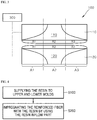
FIG. 3 is a conceptual diagram which describes a temperature adjusting arrangement of the prepreg manufacturing device according to an embodiment of the present invention. - When referring to
FIG. 3 , theprepreg manufacturing device 100 according to an embodiment of the present invention includes atemperature control part 300. - By using the
temperature control part 300, the temperatures at a plurality of (e.g., three) divided sections A1, A2, A3, which are defined in a length direction for each of the firstresin inflow part 110 and the secondresin inflow part 120, can be adjusted separately. - For example, when it is determined that the discharge amounts for the resins R1, R3, which are discharged at the A1 section and the A3 section of the first
resin inflow part 110 and the secondresin inflow part 120, are small, it is possible to increase the discharge amounts of the resins R1, R3, which are discharged at those sections, by increasing the temperatures at the A1 section and the A3 section. - Also, when it is determined that the discharge amounts for the resin R2, which is discharged at the A2 section of the first
resin inflow part 110 and the secondresin inflow part 120, are excessively large, it is possible to decrease the discharge amount of the resin R2, which is discharged at the corresponding section, by decreasing the temperatures at the A2 section. - Similarly, it is possible to impregnating reinforced fiber with the resin uniformly by dividing the upper and
lower molds -
FIG. 4 is a flowchart which schematically illustrates the prepreg manufacturing method according to another embodiment of the present invention. - When referring to
FIG. 4 , the prepreg manufacturing method as shown includes a resin supply step S100, and resin impregnation step S200. - This step is for supplying a resin, and corresponds to a step in which the resin is supplied from the extruder to each of the first resin inflow part and the second resin inflow part which are illustrated in
FIG. 2 andFIG. 3 . - As shown in
FIG. 2 , during this process which is different from conventional methods, the resin R is supplied to each of the firstresin inflow part 110 of theupper mold 10 and the secondresin inflow part 120 of thelower mold 20, such that the resin can be discharged uniformly on upper and lower portions of the reinforced fiber during subsequent processes. - This step is a resin discharge step, and corresponds to a step in which the resin is discharged uniformly from each of the first resin inflow part and the second resin inflow part toward the reinforced fiber which flows between the upper mold and the lower mold.
- When referring to
FIG. 2 , the resin R, which has be introduced to the firstresin inflow part 110 and the secondresin inflow part 120 in the previous step, is discharged uniformly toward upper and lower surfaces of the reinforced fiber (not shown) which flows between theupper mold 10 and thelower mold 20. - Meanwhile, a temperature adjusting step can be additionally performed after this step.
- The temperature adjusting step refers to a step in which temperatures at various sections are adjusted when the discharge amount of the resin R, which is discharged from the first
resin inflow part 110 and the secondresin inflow part 120, is not uniform throughout the length direction of the upper mold (or the lower mold). - For example, by referring to
FIG. 3 , when it is determined that the discharge amounts for the resins R1, R3, which are discharged at the A1 section and the A3 section of the firstresin inflow part 110 and the secondresin inflow part 120, are small, it is possible to increase the discharge amounts of the resins R1, R3, which are discharged at those sections, by increasing the temperatures at the A1 section and the A3 section. - Also, when it is determined that the discharge amounts for the resin R2, which is discharged at the A2 section of the first
resin inflow part 110 and the secondresin inflow part 120, is excessively large, it is possible to decrease the discharge amount of the resin R2, which is discharged at the corresponding section, by decreasing the temperatures at the A2 section. - Similarly, it is possible to impregnating the reinforced fiber with the resin uniformly by dividing the upper and
lower molds - By using the prepreg manufacturing method which is configured as illustrated according to the another embodiment of the present invention, uniformity of a sheet surface is obtained as the resin is simultaneously discharged to upper and lower portions of the reinforced fiber. More specifically, uniform quality of upper and lower portions of the sheet can be obtained since the reinforced fiber is positioned at a center of the height of the sheet.
- As mentioned above, according to embodiments of the invention, a uniform resin impregnation can be acquired in an impregnation mold.
- In addition, a vertical impregnation ratio deviation in the prepreg can be reduced.
- As a result, physical properties of a continuous fiber reinforced composite material can be improved, and degradation in workability due to a fiber exposure can be prevented by improving quality of upper and lower surfaces of the prepreg.
- Although the present invention has been explained by referring to the appended figures as in the above, it is to be noted than the present invention is not restricted to the embodiments and figures disclosed with this specification, and that various modifications can be made by the person having ordinary skill in the art within the scope of the technical spirit of the present invention. And, it is apparent that, although the advantageous effects according to the configuration of the present invention are not clearly written and described while explaining the embodiments of the present invention, any effect, which can be predicted by the corresponding configuration, can also be anticipated.
Claims (8)
- A prepreg manufacturing device comprising:a first resin inflow part which is formed inside an upper mold, receives a resin supplied from an extruder, and discharges the resin to a reinforced fiber flowing to a lower part in the upper mold; anda second resin inflow part which is formed inside a lower mold, receives the resin supplied from the extruder, and discharges the resin to the reinforced fiber flowing to an upper part of the lower mold.
- The prepreg manufacturing device of claim 1, wherein each of the first resin inflow part and the second resin inflow part has a shape whose cross-section size at an outlet side where the resin is discharged is expanded compared to the cross-section size at an inlet side to which the resin is supplied from the extruder.
- The prepreg manufacturing device of claim 2, wherein each of the first resin inflow part and the second resin inflow part has a triangular cross-section shape.
- The prepreg manufacturing device of claim 1, wherein the first resin inflow part and the second resin inflow part have symmetrical shapes which face each other.
- The prepreg manufacturing device of claim 1, wherein the first resin inflow part and the second resin inflow part are connected with each other at the same time through a resin supply line which is branched off from the extruder.
- The prepreg manufacturing device of claim 1, comprising temperature control parts which control temperatures at a plurality of divided sections defined in a length direction for each of the first resin inflow part and the second resin inflow part.
- A prepreg manufacturing method using the prepreg manufacturing device of any of claims 1-6, comprising:a step (a) in which a resin is supplied from the extruder to each of the first resin inflow part and the second resin inflow part; anda step (b) in which the resin is discharged uniformly from each of the first resin inflow part and the second resin inflow part toward a reinforced fiber which flows between the upper mold and the lower mold.
- The prepreg manufacturing method of claim 7, after the step (b), further comprising a step (c) in which temperatures at a plurality of divided sections defined in a length direction for each of the first resin inflow part and the second resin inflow part are controlled.
Applications Claiming Priority (2)
| Application Number | Priority Date | Filing Date | Title |
|---|---|---|---|
| KR1020160013219A KR101936584B1 (en) | 2016-02-03 | 2016-02-03 | Prepreg manufacturing apparatus and prepreg manufacturing using the same |
| PCT/KR2016/015308 WO2017135574A1 (en) | 2016-02-03 | 2016-12-27 | Prepreg manufacturing device and prepreg manufacturing method using same |
Publications (3)
| Publication Number | Publication Date |
|---|---|
| EP3412437A1 true EP3412437A1 (en) | 2018-12-12 |
| EP3412437A4 EP3412437A4 (en) | 2018-12-12 |
| EP3412437B1 EP3412437B1 (en) | 2020-01-29 |
Family
ID=59500858
Family Applications (1)
| Application Number | Title | Priority Date | Filing Date |
|---|---|---|---|
| EP16889551.4A Active EP3412437B1 (en) | 2016-02-03 | 2016-12-27 | Prepreg manufacturing device and prepreg manufacturing method using same |
Country Status (5)
| Country | Link |
|---|---|
| US (1) | US10946554B2 (en) |
| EP (1) | EP3412437B1 (en) |
| KR (1) | KR101936584B1 (en) |
| CN (1) | CN108602289B (en) |
| WO (1) | WO2017135574A1 (en) |
Family Cites Families (18)
| Publication number | Priority date | Publication date | Assignee | Title |
|---|---|---|---|---|
| FR2613661B1 (en) * | 1987-04-09 | 1989-10-06 | Atochem | PROCESS FOR PRODUCING CONTINUOUS FIBER REINFORCED THERMOPLASTIC RESIN PROFILES, APPARATUS FOR OBTAINING SAME |
| JP2787496B2 (en) | 1988-04-05 | 1998-08-20 | 3‐ディ コンポジット リミテッド | Molding method |
| JPH09136344A (en) | 1995-11-16 | 1997-05-27 | Sekisui Chem Co Ltd | Method for manufacturing tubular body |
| KR100607290B1 (en) | 1999-11-27 | 2006-07-28 | 에스케이케미칼주식회사 | Matrix resin compositions for fiber reinforced composites, prepregs and fiber reinforced composites |
| EP2644363B1 (en) * | 2002-10-09 | 2017-03-22 | Toray Industries, Inc. | Method of RTM molding |
| US20050184413A1 (en) | 2004-02-20 | 2005-08-25 | Forest Mark L.L. | Versatile mold flow capability in the infiltration of porous carbon preforms with pitch/thermoplastic/thermoset resins |
| JP4818752B2 (en) * | 2006-02-24 | 2011-11-16 | テルモ株式会社 | Injection molding die for outer cylinder for syringe, manufacturing method for outer cylinder for syringe, outer cylinder for syringe and prefilled syringe |
| JP5421625B2 (en) | 2009-03-18 | 2014-02-19 | 富士重工業株式会社 | Equipment for manufacturing fiber reinforced resin parts |
| JP5491767B2 (en) | 2009-05-26 | 2014-05-14 | パナソニック株式会社 | Method for manufacturing prepreg for printed wiring board and prepreg manufacturing apparatus for printed wiring board |
| KR20110058103A (en) | 2009-11-25 | 2011-06-01 | 삼성코닝정밀소재 주식회사 | Prepreg film manufacturing apparatus and manufacturing method for display panel |
| KR101172734B1 (en) | 2009-12-17 | 2012-08-14 | 한국철도기술연구원 | side beam and the Fabrication method for the railway bogie frame |
| CN102947076B (en) * | 2010-06-22 | 2016-01-27 | 提克纳有限责任公司 | Thermoplastic prepregs containing continuous and long fibers |
| JP5786616B2 (en) * | 2011-09-30 | 2015-09-30 | 東レ株式会社 | Method and apparatus for molding fiber reinforced plastic structure |
| CN202357450U (en) | 2011-11-24 | 2012-08-01 | 广州市博汇新材料科技有限公司 | Vacuum potting device for manufacturing carbon fibre composite plates |
| KR101377158B1 (en) | 2011-12-19 | 2014-03-26 | (주)에이티씨 | Method for Forming Fiber Reinforced Plastic Composite |
| KR20130105017A (en) | 2012-03-16 | 2013-09-25 | (주)선진오토텍 | Light-resin transfer molding apparatus for fiber-reinforced plastic |
| CN102941722A (en) | 2012-11-22 | 2013-02-27 | 中国人民解放军国防科学技术大学 | Flame-retardant corrosion-resistant case material, resin transfer molding (RTM) technique thereof and injection molding system |
| DE102014107584A1 (en) | 2014-05-28 | 2015-12-03 | Benteler Sgl Gmbh & Co. Kg | Apparatus and method for the production of fiber composite components and fiber composite component |
-
2016
- 2016-02-03 KR KR1020160013219A patent/KR101936584B1/en active Active
- 2016-12-27 EP EP16889551.4A patent/EP3412437B1/en active Active
- 2016-12-27 WO PCT/KR2016/015308 patent/WO2017135574A1/en not_active Ceased
- 2016-12-27 US US16/074,946 patent/US10946554B2/en active Active
- 2016-12-27 CN CN201680080995.4A patent/CN108602289B/en active Active
Also Published As
| Publication number | Publication date |
|---|---|
| EP3412437A4 (en) | 2018-12-12 |
| KR101936584B1 (en) | 2019-01-09 |
| KR20170092197A (en) | 2017-08-11 |
| CN108602289B (en) | 2021-01-29 |
| US10946554B2 (en) | 2021-03-16 |
| CN108602289A (en) | 2018-09-28 |
| WO2017135574A1 (en) | 2017-08-10 |
| US20190030759A1 (en) | 2019-01-31 |
| EP3412437B1 (en) | 2020-01-29 |
Similar Documents
| Publication | Publication Date | Title |
|---|---|---|
| US9186842B2 (en) | Method and device for manufacturing a dry textile preform | |
| CN106273554B (en) | Device and method for producing a composite reinforcing component | |
| CN111132844B (en) | Systems and methods for additive manufacturing of medical devices | |
| US10576663B2 (en) | Process and device for the production of a fibre-composite material | |
| EP2231908B1 (en) | Impregnation of a filament roving | |
| KR20190062911A (en) | Continuous fiber reinforced thermoplastic polymer composite and manufacturing method thereof | |
| CN104760304A (en) | Device for preparing glass fiber composite material Z-pin through ultraviolet curing quick pultrusion and preparation method of the glass fiber composite material | |
| KR20180115452A (en) | Apparatus for manufacturing tow prepreg and method for the same | |
| EP3412437B1 (en) | Prepreg manufacturing device and prepreg manufacturing method using same | |
| KR20220093745A (en) | Impregnation device for preparing unidirectional continuous fiber-reinforced thermoplastic resin composite material | |
| EP3412436B1 (en) | Prepreg preparation device and prepreg preparation method using same | |
| KR102062061B1 (en) | Heating slot die for SMC manufacturing | |
| EP3368263B1 (en) | Device for impregnation and curing of continuous fibers with resin | |
| CN116133824A (en) | Apparatus and method for producing a composite part comprising at least one layer of wound fiber-reinforced polymer | |
| JP2005335296A (en) | Tow prepreg manufacturing method | |
| KR101935509B1 (en) | Prepreg manufacturing apparatus and prepreg manufacturing using the same | |
| JP4671859B2 (en) | Long fiber reinforced thermoplastic resin material manufacturing apparatus and manufacturing method thereof | |
| Aimon et al. | Integration of soft tooling by additive manufacturing in polymer profile extrusion process chain | |
| CN111405976A (en) | Pultrusion method and pultrusion device for producing fiber-reinforced plastic profiles | |
| CN109501319A (en) | A kind of fiber impregnation device and method | |
| JP7058015B2 (en) | Continuous channel resin transfer molding method with fast cycle time | |
| US20210323251A1 (en) | Production line moulding assembly for manufacturing a non-metallic armature, production line and method of forming a rod use in the manufacture of a composite armature | |
| JP2007513313A (en) | Treater oven for prepreg manufacturing | |
| KR101552334B1 (en) | Slot-die type impregnation pin and manufacturing apparatus for continuous fiber composite | |
| JP2007076307A (en) | Resin transfer molding process |
Legal Events
| Date | Code | Title | Description |
|---|---|---|---|
| STAA | Information on the status of an ep patent application or granted ep patent |
Free format text: STATUS: THE INTERNATIONAL PUBLICATION HAS BEEN MADE |
|
| PUAI | Public reference made under article 153(3) epc to a published international application that has entered the european phase |
Free format text: ORIGINAL CODE: 0009012 |
|
| STAA | Information on the status of an ep patent application or granted ep patent |
Free format text: STATUS: REQUEST FOR EXAMINATION WAS MADE |
|
| 17P | Request for examination filed |
Effective date: 20180806 |
|
| A4 | Supplementary search report drawn up and despatched |
Effective date: 20181004 |
|
| AK | Designated contracting states |
Kind code of ref document: A1 Designated state(s): AL AT BE BG CH CY CZ DE DK EE ES FI FR GB GR HR HU IE IS IT LI LT LU LV MC MK MT NL NO PL PT RO RS SE SI SK SM TR |
|
| AX | Request for extension of the european patent |
Extension state: BA ME |
|
| DAV | Request for validation of the european patent (deleted) | ||
| DAX | Request for extension of the european patent (deleted) | ||
| GRAP | Despatch of communication of intention to grant a patent |
Free format text: ORIGINAL CODE: EPIDOSNIGR1 |
|
| STAA | Information on the status of an ep patent application or granted ep patent |
Free format text: STATUS: GRANT OF PATENT IS INTENDED |
|
| INTG | Intention to grant announced |
Effective date: 20190719 |
|
| GRAS | Grant fee paid |
Free format text: ORIGINAL CODE: EPIDOSNIGR3 |
|
| GRAA | (expected) grant |
Free format text: ORIGINAL CODE: 0009210 |
|
| STAA | Information on the status of an ep patent application or granted ep patent |
Free format text: STATUS: THE PATENT HAS BEEN GRANTED |
|
| AK | Designated contracting states |
Kind code of ref document: B1 Designated state(s): AL AT BE BG CH CY CZ DE DK EE ES FI FR GB GR HR HU IE IS IT LI LT LU LV MC MK MT NL NO PL PT RO RS SE SI SK SM TR |
|
| REG | Reference to a national code |
Ref country code: GB Ref legal event code: FG4D |
|
| REG | Reference to a national code |
Ref country code: CH Ref legal event code: EP |
|
| REG | Reference to a national code |
Ref country code: AT Ref legal event code: REF Ref document number: 1228182 Country of ref document: AT Kind code of ref document: T Effective date: 20200215 |
|
| REG | Reference to a national code |
Ref country code: IE Ref legal event code: FG4D |
|
| REG | Reference to a national code |
Ref country code: DE Ref legal event code: R096 Ref document number: 602016028987 Country of ref document: DE |
|
| REG | Reference to a national code |
Ref country code: NL Ref legal event code: FP |
|
| PG25 | Lapsed in a contracting state [announced via postgrant information from national office to epo] |
Ref country code: PT Free format text: LAPSE BECAUSE OF FAILURE TO SUBMIT A TRANSLATION OF THE DESCRIPTION OR TO PAY THE FEE WITHIN THE PRESCRIBED TIME-LIMIT Effective date: 20200621 Ref country code: RS Free format text: LAPSE BECAUSE OF FAILURE TO SUBMIT A TRANSLATION OF THE DESCRIPTION OR TO PAY THE FEE WITHIN THE PRESCRIBED TIME-LIMIT Effective date: 20200129 Ref country code: FI Free format text: LAPSE BECAUSE OF FAILURE TO SUBMIT A TRANSLATION OF THE DESCRIPTION OR TO PAY THE FEE WITHIN THE PRESCRIBED TIME-LIMIT Effective date: 20200129 Ref country code: NO Free format text: LAPSE BECAUSE OF FAILURE TO SUBMIT A TRANSLATION OF THE DESCRIPTION OR TO PAY THE FEE WITHIN THE PRESCRIBED TIME-LIMIT Effective date: 20200429 |
|
| REG | Reference to a national code |
Ref country code: LT Ref legal event code: MG4D |
|
| PG25 | Lapsed in a contracting state [announced via postgrant information from national office to epo] |
Ref country code: IS Free format text: LAPSE BECAUSE OF FAILURE TO SUBMIT A TRANSLATION OF THE DESCRIPTION OR TO PAY THE FEE WITHIN THE PRESCRIBED TIME-LIMIT Effective date: 20200529 Ref country code: GR Free format text: LAPSE BECAUSE OF FAILURE TO SUBMIT A TRANSLATION OF THE DESCRIPTION OR TO PAY THE FEE WITHIN THE PRESCRIBED TIME-LIMIT Effective date: 20200430 Ref country code: BG Free format text: LAPSE BECAUSE OF FAILURE TO SUBMIT A TRANSLATION OF THE DESCRIPTION OR TO PAY THE FEE WITHIN THE PRESCRIBED TIME-LIMIT Effective date: 20200429 Ref country code: SE Free format text: LAPSE BECAUSE OF FAILURE TO SUBMIT A TRANSLATION OF THE DESCRIPTION OR TO PAY THE FEE WITHIN THE PRESCRIBED TIME-LIMIT Effective date: 20200129 Ref country code: LV Free format text: LAPSE BECAUSE OF FAILURE TO SUBMIT A TRANSLATION OF THE DESCRIPTION OR TO PAY THE FEE WITHIN THE PRESCRIBED TIME-LIMIT Effective date: 20200129 Ref country code: HR Free format text: LAPSE BECAUSE OF FAILURE TO SUBMIT A TRANSLATION OF THE DESCRIPTION OR TO PAY THE FEE WITHIN THE PRESCRIBED TIME-LIMIT Effective date: 20200129 |
|
| REG | Reference to a national code |
Ref country code: AT Ref legal event code: UEP Ref document number: 1228182 Country of ref document: AT Kind code of ref document: T Effective date: 20200129 |
|
| PG25 | Lapsed in a contracting state [announced via postgrant information from national office to epo] |
Ref country code: RO Free format text: LAPSE BECAUSE OF FAILURE TO SUBMIT A TRANSLATION OF THE DESCRIPTION OR TO PAY THE FEE WITHIN THE PRESCRIBED TIME-LIMIT Effective date: 20200129 Ref country code: ES Free format text: LAPSE BECAUSE OF FAILURE TO SUBMIT A TRANSLATION OF THE DESCRIPTION OR TO PAY THE FEE WITHIN THE PRESCRIBED TIME-LIMIT Effective date: 20200129 Ref country code: SM Free format text: LAPSE BECAUSE OF FAILURE TO SUBMIT A TRANSLATION OF THE DESCRIPTION OR TO PAY THE FEE WITHIN THE PRESCRIBED TIME-LIMIT Effective date: 20200129 Ref country code: EE Free format text: LAPSE BECAUSE OF FAILURE TO SUBMIT A TRANSLATION OF THE DESCRIPTION OR TO PAY THE FEE WITHIN THE PRESCRIBED TIME-LIMIT Effective date: 20200129 Ref country code: LT Free format text: LAPSE BECAUSE OF FAILURE TO SUBMIT A TRANSLATION OF THE DESCRIPTION OR TO PAY THE FEE WITHIN THE PRESCRIBED TIME-LIMIT Effective date: 20200129 Ref country code: DK Free format text: LAPSE BECAUSE OF FAILURE TO SUBMIT A TRANSLATION OF THE DESCRIPTION OR TO PAY THE FEE WITHIN THE PRESCRIBED TIME-LIMIT Effective date: 20200129 Ref country code: SK Free format text: LAPSE BECAUSE OF FAILURE TO SUBMIT A TRANSLATION OF THE DESCRIPTION OR TO PAY THE FEE WITHIN THE PRESCRIBED TIME-LIMIT Effective date: 20200129 Ref country code: CZ Free format text: LAPSE BECAUSE OF FAILURE TO SUBMIT A TRANSLATION OF THE DESCRIPTION OR TO PAY THE FEE WITHIN THE PRESCRIBED TIME-LIMIT Effective date: 20200129 |
|
| REG | Reference to a national code |
Ref country code: DE Ref legal event code: R097 Ref document number: 602016028987 Country of ref document: DE |
|
| PLBE | No opposition filed within time limit |
Free format text: ORIGINAL CODE: 0009261 |
|
| STAA | Information on the status of an ep patent application or granted ep patent |
Free format text: STATUS: NO OPPOSITION FILED WITHIN TIME LIMIT |
|
| 26N | No opposition filed |
Effective date: 20201030 |
|
| PG25 | Lapsed in a contracting state [announced via postgrant information from national office to epo] |
Ref country code: IT Free format text: LAPSE BECAUSE OF FAILURE TO SUBMIT A TRANSLATION OF THE DESCRIPTION OR TO PAY THE FEE WITHIN THE PRESCRIBED TIME-LIMIT Effective date: 20200129 |
|
| PG25 | Lapsed in a contracting state [announced via postgrant information from national office to epo] |
Ref country code: PL Free format text: LAPSE BECAUSE OF FAILURE TO SUBMIT A TRANSLATION OF THE DESCRIPTION OR TO PAY THE FEE WITHIN THE PRESCRIBED TIME-LIMIT Effective date: 20200129 Ref country code: SI Free format text: LAPSE BECAUSE OF FAILURE TO SUBMIT A TRANSLATION OF THE DESCRIPTION OR TO PAY THE FEE WITHIN THE PRESCRIBED TIME-LIMIT Effective date: 20200129 |
|
| REG | Reference to a national code |
Ref country code: CH Ref legal event code: PL |
|
| GBPC | Gb: european patent ceased through non-payment of renewal fee |
Effective date: 20201227 |
|
| PG25 | Lapsed in a contracting state [announced via postgrant information from national office to epo] |
Ref country code: MC Free format text: LAPSE BECAUSE OF FAILURE TO SUBMIT A TRANSLATION OF THE DESCRIPTION OR TO PAY THE FEE WITHIN THE PRESCRIBED TIME-LIMIT Effective date: 20200129 |
|
| REG | Reference to a national code |
Ref country code: BE Ref legal event code: MM Effective date: 20201231 |
|
| PG25 | Lapsed in a contracting state [announced via postgrant information from national office to epo] |
Ref country code: LU Free format text: LAPSE BECAUSE OF NON-PAYMENT OF DUE FEES Effective date: 20201227 Ref country code: IE Free format text: LAPSE BECAUSE OF NON-PAYMENT OF DUE FEES Effective date: 20201227 |
|
| PG25 | Lapsed in a contracting state [announced via postgrant information from national office to epo] |
Ref country code: GB Free format text: LAPSE BECAUSE OF NON-PAYMENT OF DUE FEES Effective date: 20201227 Ref country code: LI Free format text: LAPSE BECAUSE OF NON-PAYMENT OF DUE FEES Effective date: 20201231 Ref country code: CH Free format text: LAPSE BECAUSE OF NON-PAYMENT OF DUE FEES Effective date: 20201231 |
|
| PG25 | Lapsed in a contracting state [announced via postgrant information from national office to epo] |
Ref country code: TR Free format text: LAPSE BECAUSE OF FAILURE TO SUBMIT A TRANSLATION OF THE DESCRIPTION OR TO PAY THE FEE WITHIN THE PRESCRIBED TIME-LIMIT Effective date: 20200129 Ref country code: MT Free format text: LAPSE BECAUSE OF FAILURE TO SUBMIT A TRANSLATION OF THE DESCRIPTION OR TO PAY THE FEE WITHIN THE PRESCRIBED TIME-LIMIT Effective date: 20200129 Ref country code: CY Free format text: LAPSE BECAUSE OF FAILURE TO SUBMIT A TRANSLATION OF THE DESCRIPTION OR TO PAY THE FEE WITHIN THE PRESCRIBED TIME-LIMIT Effective date: 20200129 |
|
| PG25 | Lapsed in a contracting state [announced via postgrant information from national office to epo] |
Ref country code: MK Free format text: LAPSE BECAUSE OF FAILURE TO SUBMIT A TRANSLATION OF THE DESCRIPTION OR TO PAY THE FEE WITHIN THE PRESCRIBED TIME-LIMIT Effective date: 20200129 Ref country code: AL Free format text: LAPSE BECAUSE OF FAILURE TO SUBMIT A TRANSLATION OF THE DESCRIPTION OR TO PAY THE FEE WITHIN THE PRESCRIBED TIME-LIMIT Effective date: 20200129 |
|
| PG25 | Lapsed in a contracting state [announced via postgrant information from national office to epo] |
Ref country code: BE Free format text: LAPSE BECAUSE OF NON-PAYMENT OF DUE FEES Effective date: 20201231 |
|
| PGFP | Annual fee paid to national office [announced via postgrant information from national office to epo] |
Ref country code: AT Payment date: 20221005 Year of fee payment: 7 |
|
| REG | Reference to a national code |
Ref country code: DE Ref legal event code: R082 Ref document number: 602016028987 Country of ref document: DE Representative=s name: KANDLBINDER, MARKUS, DIPL.-PHYS., DE |
|
| REG | Reference to a national code |
Ref country code: AT Ref legal event code: MM01 Ref document number: 1228182 Country of ref document: AT Kind code of ref document: T Effective date: 20231227 |
|
| PGFP | Annual fee paid to national office [announced via postgrant information from national office to epo] |
Ref country code: FR Payment date: 20240909 Year of fee payment: 9 |
|
| PGFP | Annual fee paid to national office [announced via postgrant information from national office to epo] |
Ref country code: NL Payment date: 20240905 Year of fee payment: 9 |
|
| PG25 | Lapsed in a contracting state [announced via postgrant information from national office to epo] |
Ref country code: AT Free format text: LAPSE BECAUSE OF NON-PAYMENT OF DUE FEES Effective date: 20231227 |
|
| PG25 | Lapsed in a contracting state [announced via postgrant information from national office to epo] |
Ref country code: AT Free format text: LAPSE BECAUSE OF NON-PAYMENT OF DUE FEES Effective date: 20231227 |
|
| PGFP | Annual fee paid to national office [announced via postgrant information from national office to epo] |
Ref country code: DE Payment date: 20250908 Year of fee payment: 10 |
|
| REG | Reference to a national code |
Ref country code: NL Ref legal event code: MM Effective date: 20260101 |