EP3412410A1 - Hook apparatus for centering and clamping workpieces, particularly sheets - Google Patents
Hook apparatus for centering and clamping workpieces, particularly sheets Download PDFInfo
- Publication number
- EP3412410A1 EP3412410A1 EP18000503.5A EP18000503A EP3412410A1 EP 3412410 A1 EP3412410 A1 EP 3412410A1 EP 18000503 A EP18000503 A EP 18000503A EP 3412410 A1 EP3412410 A1 EP 3412410A1
- Authority
- EP
- European Patent Office
- Prior art keywords
- pin
- hooking member
- rod
- main body
- shaped
- Prior art date
- Legal status (The legal status is an assumption and is not a legal conclusion. Google has not performed a legal analysis and makes no representation as to the accuracy of the status listed.)
- Granted
Links
Images


Classifications
-
- B—PERFORMING OPERATIONS; TRANSPORTING
- B25—HAND TOOLS; PORTABLE POWER-DRIVEN TOOLS; MANIPULATORS
- B25B—TOOLS OR BENCH DEVICES NOT OTHERWISE PROVIDED FOR, FOR FASTENING, CONNECTING, DISENGAGING, OR HOLDING
- B25B5/00—Clamps
- B25B5/06—Arrangements for positively actuating jaws
- B25B5/061—Arrangements for positively actuating jaws with fluid drive
- B25B5/064—Arrangements for positively actuating jaws with fluid drive with clamping means pivoting around an axis perpendicular to the pressing direction
-
- B—PERFORMING OPERATIONS; TRANSPORTING
- B25—HAND TOOLS; PORTABLE POWER-DRIVEN TOOLS; MANIPULATORS
- B25B—TOOLS OR BENCH DEVICES NOT OTHERWISE PROVIDED FOR, FOR FASTENING, CONNECTING, DISENGAGING, OR HOLDING
- B25B5/00—Clamps
- B25B5/06—Arrangements for positively actuating jaws
- B25B5/08—Arrangements for positively actuating jaws using cams
- B25B5/087—Arrangements for positively actuating jaws using cams actuated by a hydraulic or pneumatic piston
Definitions
- the present invention relates in general to apparatuses used in automatic processing lines for centering a workpiece, for example a metal sheet, and for locking it at a side edge thereof or at the edge of a hole formed therein, with the aim of holding the workpiece in a predetermined position to allow a processing to be executed, such as a welding, a bending or a similar operation.
- An apparatus of such a type which is known from DE-393 63 29 or from EP-1 393 861 , allows a workpiece in the form of a metal sheet, having a single predetermined thickness, to be clamped.
- the invention relates to an apparatus of the type defined in the preamble of appended claim 1.
- An apparatus of the type defined above which is known from EP-2 626 174 , allows sheets the thickness of which is comprised in a predefined thickness range, to be clamped in a predetermined position.
- This apparatus although satisfactory, takes up a large amount of space, which makes it unsuitable for use in some applications.
- the object of the present invention is to provide an apparatus of the type mentioned above, which allows workpieces of different thickness to be centered and clamped and which, at the same time, takes up a minimal amount of space and has a relatively high clamping force, and the structure of which is particularly compact and light so as to allow it to be used in apparatuses in which reduced handling spaces are available and/or to be used by industrial robots.
- the apparatus comprises a part connected to the control rod, which includes an auxiliary shaped body fixed to the rod at its side facing the hooking member, and has a slit in which a first transverse pin is slidably engaged, which pin also engages a hole of the first arm of said at least one L-shaped member, the apparatus of the invention has a very compact and light structure which allows a high clamping force to be developed.
- said slit is substantially arch-shaped and has a transverse section engageable by the first pin when the hooking member is in said resting position, and a section inclined with respect to the axis of said rod, which can be engaged by the first pin when the hooking member is in said clamping position, the inclination of said inclined section being such that the engagement of the first pin therein, in the absence of an axial displacement of the rod, causes the movement of said hooking member to be locked, in order to make irreversible the position of the hooking member.
- the movement of the coupling element of the apparatus is irreversible, and it allows the clamping action exerted on a workpiece to be deactivated only as a result of the displacement of the control rod, which makes the apparatus safe in operation.
- the structure of the apparatus is relatively simple, and therefore light and compact, while it allows workpieces of different thicknesses to be clamped.
- the apparatus comprises a second pin parallel to said first pin, which is slidably inserted into a slot of the second arm of said at least one L-shaped member and into a hole formed in a foot portion of the hooking member.
- the apparatus comprises a third pin parallel to said first pin, which engages a second hole formed in said foot portion of the hooking member, both said second and third pin engaging at least one substantially arch-shaped guide groove formed in the body of the apparatus and being part of said guide means. In this manner, the movement of the hooking member is guided reliably and precisely with respect to the main body of the apparatus.
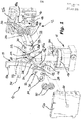
- an apparatus according to the invention which is intended for centering and clamping workpieces such as metal sheets, is indicated 10 as a whole.
- the apparatus 10 comprises a main body 12 to which a driving unit is fixed in its lower part (with reference to the figures), which unit, in the embodiment shown, consists of an actuating cylinder 14, conveniently pneumatic and typically of the double-acting type, controlled by a pressurized fluid.
- the body 12 comprises a pair of half-shells 12a, 12b which delimit, in their coupled condition, an inner cavity of the body 12.
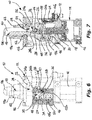
- the cylinder 14 comprises a chamber 16 ( Figure 7 ) in which a piston 18 is sealably and slidably mounted, which is fixed to the lower end of a control rod 20 that extends at least partially into the cavity defined by the half-shells 12a and 12b.
- the rod 20, as a result of sliding of the piston 18 in the chamber 16, can reach a series of axial positions with respect to the main body 12, in particular a completely lowered position and a plurality of raised positions, in order to control the displacement of a hooking member 19 that extends in part into the cavity defined between the half-shells 12a and 12b, the function of which is to clamp a workpiece (not shown), with respect to the apparatus 10.
- the hooking member 19 has a general stem shape and comprises a typically hook-shaped upper end 19a, and an opposite foot portion 19b. It is movable between a resting position, corresponding to the completely lowered position of the rod 20, and a series of clamping positions, corresponding to the aforesaid plurality of raised positions, as a function of the thickness of a workpiece to be clamped.
- the movement of the hooking member 19 is caused by control means described in greater detail below.
- a shaped auxiliary body 22 having a substantially trapezoidal shape in a side view, is fixed, for example by means of a screw.
- a through slit 24 having an arched shape is provided in this auxiliary body 22, which comprises a first section 24a transverse to the rod 20, and a second section 24b inclined of a predetermined small angle with respect to the rod 20, the purpose of which will be further clarified in the following.
- the slit 24 is slidably engaged by a first transverse pin 26, preferably with the interposition of a rolling bearing 28 between a central zone of the pin 26 and the surface of the slit 24.
- the presence of the shaped body 22 with its slit 24 engaged by the pin 26, allows the overall dimensions of the apparatus 10 to be made considerably smaller, and to reduce the weight in a sensitive manner, which are fundamental aspects for allowing the apparatus 10 to be used in applications in which it is moved by means of robotized devices or its operation occurs in limited spaces.
- the opposite ends of the pin 26 are engaged in respective holes 30 formed in a first arm of a pair of equal L-shaped members 32, arranged at the opposite sides of the shaped body 22.
- Each L-shaped member 32 has a second arm in which a slot 34 is formed.
- the two slots 34 of the two L-shaped members 32 are slidably engaged by a second transverse pin 36, parallel to the first pin 26.
- each L-shaped member 32 In an intermediate zone of each L-shaped member 32, between its two arms, a hole 38 is formed in which a half-pin 40 is inserted, which extends from a respective half-shell 12a, 12b.
- the two half-pins 40 In the coupled condition of the half-shells 12a and 12b, the two half-pins 40 are coaxial, so as to define together a common articulation axis of the two L-shaped members 32, which are therefore swingably mounted within the body 12.
- a pair of through holes, respectively indicated 42 and 44, are formed in the foot portion 19b of the hooking member 19.
- the opposite axial ends of the pins 36 and 46 extend up to the half-shells 12a and 12b to engage respective guide formations of the body 12 in order to keep the hooking member 19 in a predetermined configuration during the movement between its resting and clamping positions.
- the hooking member 19 remains substantially parallel to itself, and its inclination varies by a small angle with respect to the axis of the rod 20.
- the aforesaid formations consist of a pair of symmetrical guide grooves 48, each formed by milling a respective half-shell 12a, 12b.
- Each groove 48 has an overall arched shape defined by an upper arch-shaped portion 48a and by a lower rectilinear portion 48b ( Figures 1 and 5 ). Conveniently, each axial end of the pins 36 and 46 engages a respective groove 48, with the interposition of a rolling bearing 50.
- the intermediate part of the hooking member 19 projects above the half-shells 12a and 12b through an opening 52 formed in a shield plate 54 that is slidably mounted in the direction transverse to the axis of the rod 20.
- This plate 54 covers a widest opening facing the internal cavity of the body 12, in order to prevent foreign bodies from entering the body 12 during use of the apparatus 10, and interfering with the control means for controlling the movement of the hooking member 19.
- the opening 52 has a size substantially corresponding to the cross-section of the intermediate part of the hooking member 19, and has therefore a narrower width with respect to that of the widest opening facing the cavity of the body 12.
- the hooking member 19, during operation of the apparatus 10, undergoes a small transverse movement with respect to the body 12, and carries with it the shield plate 54.
- a stationary covering plate 56 is fixed to the half-shells 12a and 12b, from which an axial centering pin 58 extends upwardly, on the side opposite the cylinder 14, to which a collar 62 is associated.
- the centering pin 58 has a slightly conical shape and it is intended to be inserted into a corresponding hole of a workpiece to be clamped by the apparatus 10.
- a recess 60 is formed inside the centering pin 58, within which the hook end 19a of the member 19 is received with a small clearance. In particular, when the hooking member 19 is in its resting position, the hook end 19a is completely received into the recess 60.
- the collar 62 that surrounds the pin 58 defines at its upper edge a resting zone for resting the workpiece to be clamped, which is arranged beneath the hook end 19a when the hooking member 19 is in one of the clamping positions thereof. Therefore, the support zone of the apparatus 10 cooperates with the hook end 19a, in the aforementioned clamping positions, to clamp a workpiece with respect to the apparatus 10.
- a removable side plate 64 is applied to the half-shells 12a and 12b, to which a pair of microswitches 66a, 66b ( Figures 4 and 7 ) are fixed, in order to detect the opposite end-of-travel positions of the rod 20 by means of a check element 68 that projects from the shaped body 22.
- a workpiece such as a metal sheet, for example provided with a hole of predetermined size
- the hooking member 19 is in the resting position shown in Figures 2 and 3 , with the hook end 19a thereof fully recovered inside the recess 60.
- the rod 20 is in its fully lowered position, the first pin 26 engages the transverse section 24a of the slit 24 of the shaped body 22, and the opposite axial ends of the second pin 36 engage the upper arcuate portion 48a of the grooves 48 of the two half-shells 12a and 12b.
- the second pin 36 moves from the upper arch-shaped portion 48a to the lower rectilinear portion 48b of the grooves 48, causing the hooking member 19 to undergo a small counter-clockwise rotation (with reference to the figures), and to move downward in the direction of the cylinder 14.
- the hooking member 19 passes from its resting position, in which its hook end is received in the recess 60 and is substantially spaced from the edge of the collar 62, to a first clamping position in which its hook end 19a projects partially outside of the recess 60, and it is close to the edge of the collar 62, as shown in Figure 4 .
- the hook end 19a of the hooking member 19 is separated from the upper edge of the collar 62 by a distance indicated in Figure 4 by "X max", which corresponds to the maximum thickness of a workpiece to be clamped by means of the apparatus 10.
- the pin 26 engages the inclined section 24b of the slit 24, which section is inclined of a small angle with respect to the axial direction identified by the rod 20, such that, in the absence of an axial displacement of the rod 20 and of the shaped body 22 consequent to a variation of the position of the piston 18 in the cylinder 14, a sliding of the pin 26 along the slit 24 is prevented by the position of the L-shaped members 32, and therefore an accidental displacement of the hooking member 19 from the reached clamping position is prevented, whereby its position is irreversible.
- This feature is particularly useful in the case of an accidental interruption of the supply of pressurized fluid to the cylinder 14, for example as a result of an interruption of the power supply to the system that manages the operation of the apparatus 10.
- the hooking member 19 remains in the clamping position as long as the piston 18 undergoes a displacement controlled by the pressurized fluid in the cylinder 14.
- a further thrust applied to the piston 18 causes an additional raising of the rod 20 and of the shaped body 22.
- This raising causes a displacement of the pin 26 towards the bottom of the inclined section 24b of the slit 24, which causes the L-shaped members 32 to undergo a further rotation in the anti-clockwise direction, and the second and the third pins 36 and 46 to undergo another displacement towards the lower rectilinear portion 48b of the grooves 48. Therefore, a further lowering of the hooking member 19 takes place, which allows its hook end 19a to be brought into a position closer to the upper edge of the collar 62 with respect to the aforementioned "X max" distance, which corresponds to the thickness of the workpiece to be clamped.
- the minimum thickness of a workpiece to be clamped by the apparatus 10 corresponds to the distance "X min" (see figures 5 to 7 ) between the edge of the collar 62 and the hook end 19a, which is reached when the pin 26 is arranged at the bottom of the inclined section 24b of the slit 24.
- the third pin 46 is generally arranged at the bottom, or in a position adjacent thereto, of the rectilinear portion 48b of the grooves 48 (see in particular Figure 6 ).
- the apparatus 10 of the invention automatically adapts to clamp workpieces or sheets having a thickness included in the "X max"/"X min" range, which can usually correspond to 0.5 mm or more, while maintaining a high clamping force.
- the length of the inclined section 24b of the slit 24, and also of the rectilinear lower portions 48b of the grooves 48 allows the width of the thickness range "X max"/"X min" of the workpieces that can be locked through the apparatus 10, to be determined, by preserving the irreversibility of the device for any position of the pin 26 with respect to this inclined section.
Landscapes
- Engineering & Computer Science (AREA)
- Mechanical Engineering (AREA)
- Jigs For Machine Tools (AREA)
Abstract
Description
- The present invention relates in general to apparatuses used in automatic processing lines for centering a workpiece, for example a metal sheet, and for locking it at a side edge thereof or at the edge of a hole formed therein, with the aim of holding the workpiece in a predetermined position to allow a processing to be executed, such as a welding, a bending or a similar operation.
- An apparatus of such a type, which is known from
DE-393 63 29 or fromEP-1 393 861 , allows a workpiece in the form of a metal sheet, having a single predetermined thickness, to be clamped. - In particular, the invention relates to an apparatus of the type defined in the preamble of appended claim 1.
- An apparatus of the type defined above, which is known from
EP-2 626 174 , allows sheets the thickness of which is comprised in a predefined thickness range, to be clamped in a predetermined position. This apparatus, although satisfactory, takes up a large amount of space, which makes it unsuitable for use in some applications. - The object of the present invention is to provide an apparatus of the type mentioned above, which allows workpieces of different thickness to be centered and clamped and which, at the same time, takes up a minimal amount of space and has a relatively high clamping force, and the structure of which is particularly compact and light so as to allow it to be used in apparatuses in which reduced handling spaces are available and/or to be used by industrial robots.
- This object is achieved by virtue of an apparatus having the features mentioned in the appended claims.
- In particular, by virtue of the fact that the apparatus comprises a part connected to the control rod, which includes an auxiliary shaped body fixed to the rod at its side facing the hooking member, and has a slit in which a first transverse pin is slidably engaged, which pin also engages a hole of the first arm of said at least one L-shaped member, the apparatus of the invention has a very compact and light structure which allows a high clamping force to be developed.
- According to a preferred feature of the invention, said slit is substantially arch-shaped and has a transverse section engageable by the first pin when the hooking member is in said resting position, and a section inclined with respect to the axis of said rod, which can be engaged by the first pin when the hooking member is in said clamping position, the inclination of said inclined section being such that the engagement of the first pin therein, in the absence of an axial displacement of the rod, causes the movement of said hooking member to be locked, in order to make irreversible the position of the hooking member. Thanks to these features, the movement of the coupling element of the apparatus is irreversible, and it allows the clamping action exerted on a workpiece to be deactivated only as a result of the displacement of the control rod, which makes the apparatus safe in operation. Moreover, the structure of the apparatus is relatively simple, and therefore light and compact, while it allows workpieces of different thicknesses to be clamped.
- According to another preferred feature of the invention, the apparatus comprises a second pin parallel to said first pin, which is slidably inserted into a slot of the second arm of said at least one L-shaped member and into a hole formed in a foot portion of the hooking member. This makes it possible to connect the movement of the hooking member with the movement of the first pin in the slit of the shaped body in a highly reliable manner, by means of said at least one L-shaped member.
- According to still another preferred feature of the invention, the apparatus comprises a third pin parallel to said first pin, which engages a second hole formed in said foot portion of the hooking member, both said second and third pin engaging at least one substantially arch-shaped guide groove formed in the body of the apparatus and being part of said guide means. In this manner, the movement of the hooking member is guided reliably and precisely with respect to the main body of the apparatus.
- Further characteristics and advantages of the invention will be made clearer by the following detailed description, provided purely by way of non-limiting example and referred to the appended drawings in which:
-
Figure 1 is an exploded perspective view of the main components of an apparatus according to the invention, -
Figure 2 is a partially sectional side elevational view of the apparatus ofFigure 1 , in its resting condition in which the hooking member is spaced from a resting zone of a workpiece to be clamped, -
Figure 3 is a view similar to that ofFigure 1 , in which the main body of the apparatus is in the open condition and is sectioned along a median plane, -
Figures 4 and 5 are views similar toFigure 3 , which illustrate positions of the apparatus that correspond to the locking of a workpiece of a maximum thickness and of a workpiece of a minimum thickness, respectively, -
Figure 6 is a view similar toFigure 2 , in which the hooking member of the apparatus is in the locking position of a workpiece of a minimum thickness, and -
Figure 7 is a side elevational view of the apparatus fully sectioned along a median plane, in its locking position shown inFigure 6 . - With reference to the drawings, an apparatus according to the invention, which is intended for centering and clamping workpieces such as metal sheets, is indicated 10 as a whole.
- The
apparatus 10 comprises amain body 12 to which a driving unit is fixed in its lower part (with reference to the figures), which unit, in the embodiment shown, consists of an actuatingcylinder 14, conveniently pneumatic and typically of the double-acting type, controlled by a pressurized fluid. Thebody 12 comprises a pair of half-shells body 12. - The
cylinder 14 comprises a chamber 16 (Figure 7 ) in which apiston 18 is sealably and slidably mounted, which is fixed to the lower end of acontrol rod 20 that extends at least partially into the cavity defined by the half-shells rod 20, as a result of sliding of thepiston 18 in thechamber 16, can reach a series of axial positions with respect to themain body 12, in particular a completely lowered position and a plurality of raised positions, in order to control the displacement of a hookingmember 19 that extends in part into the cavity defined between the half-shells apparatus 10. - The hooking
member 19 has a general stem shape and comprises a typically hook-shapedupper end 19a, and anopposite foot portion 19b. It is movable between a resting position, corresponding to the completely lowered position of therod 20, and a series of clamping positions, corresponding to the aforesaid plurality of raised positions, as a function of the thickness of a workpiece to be clamped. - The movement of the hooking
member 19 is caused by control means described in greater detail below. - At the end of the
rod 20 opposite to thepiston 18, a shapedauxiliary body 22, having a substantially trapezoidal shape in a side view, is fixed, for example by means of a screw. A throughslit 24 having an arched shape is provided in thisauxiliary body 22, which comprises afirst section 24a transverse to therod 20, and asecond section 24b inclined of a predetermined small angle with respect to therod 20, the purpose of which will be further clarified in the following. - The
slit 24 is slidably engaged by a firsttransverse pin 26, preferably with the interposition of a rolling bearing 28 between a central zone of thepin 26 and the surface of theslit 24. The presence of theshaped body 22 with itsslit 24 engaged by thepin 26, allows the overall dimensions of theapparatus 10 to be made considerably smaller, and to reduce the weight in a sensitive manner, which are fundamental aspects for allowing theapparatus 10 to be used in applications in which it is moved by means of robotized devices or its operation occurs in limited spaces. - The opposite ends of the
pin 26 are engaged inrespective holes 30 formed in a first arm of a pair of equal L-shaped members 32, arranged at the opposite sides of theshaped body 22. - Each L-
shaped member 32 has a second arm in which aslot 34 is formed. The twoslots 34 of the two L-shaped members 32 are slidably engaged by a secondtransverse pin 36, parallel to thefirst pin 26. - In an intermediate zone of each L-
shaped member 32, between its two arms, ahole 38 is formed in which a half-pin 40 is inserted, which extends from a respective half-shell shells pins 40 are coaxial, so as to define together a common articulation axis of the two L-shaped members 32, which are therefore swingably mounted within thebody 12. - A pair of through holes, respectively indicated 42 and 44, are formed in the
foot portion 19b of the hookingmember 19. Thehole 42, closer to thehook end 19a, is engaged by a central portion of thetransverse pin 36, while thehole 44, farthest from thehook end 19a, is engaged by a central portion of a thirdtransverse pin 46, parallel to thepin 36. - The opposite axial ends of the
pins shells body 12 in order to keep the hookingmember 19 in a predetermined configuration during the movement between its resting and clamping positions. In particular, when passing between one and the other of these positions, the hookingmember 19 remains substantially parallel to itself, and its inclination varies by a small angle with respect to the axis of therod 20. The aforesaid formations consist of a pair ofsymmetrical guide grooves 48, each formed by milling a respective half-shell - Each
groove 48 has an overall arched shape defined by an upper arch-shaped portion 48a and by a lowerrectilinear portion 48b (Figures 1 and5 ). Conveniently, each axial end of thepins respective groove 48, with the interposition of a rollingbearing 50. - The intermediate part of the hooking
member 19 projects above the half-shells opening 52 formed in ashield plate 54 that is slidably mounted in the direction transverse to the axis of therod 20. Thisplate 54 covers a widest opening facing the internal cavity of thebody 12, in order to prevent foreign bodies from entering thebody 12 during use of theapparatus 10, and interfering with the control means for controlling the movement of the hookingmember 19. Theopening 52 has a size substantially corresponding to the cross-section of the intermediate part of the hookingmember 19, and has therefore a narrower width with respect to that of the widest opening facing the cavity of thebody 12. The hookingmember 19, during operation of theapparatus 10, undergoes a small transverse movement with respect to thebody 12, and carries with it theshield plate 54. - Above the
plate 54, astationary covering plate 56 is fixed to the half-shells pin 58 extends upwardly, on the side opposite thecylinder 14, to which acollar 62 is associated. - Preferably, the centering
pin 58 has a slightly conical shape and it is intended to be inserted into a corresponding hole of a workpiece to be clamped by theapparatus 10. Arecess 60 is formed inside the centeringpin 58, within which thehook end 19a of themember 19 is received with a small clearance. In particular, when the hookingmember 19 is in its resting position, thehook end 19a is completely received into therecess 60. - The
collar 62 that surrounds thepin 58 defines at its upper edge a resting zone for resting the workpiece to be clamped, which is arranged beneath thehook end 19a when the hookingmember 19 is in one of the clamping positions thereof. Therefore, the support zone of theapparatus 10 cooperates with thehook end 19a, in the aforementioned clamping positions, to clamp a workpiece with respect to theapparatus 10. - Moreover, a
removable side plate 64 is applied to the half-shells microswitches 66a, 66b (Figures 4 and7 ) are fixed, in order to detect the opposite end-of-travel positions of therod 20 by means of acheck element 68 that projects from theshaped body 22. - In the operation, a workpiece such as a metal sheet, for example provided with a hole of predetermined size, is approached to the
apparatus 10 in such a manner to engage the centeringpin 58 in the aforesaid hole, until the workpiece rests on the upper edge of thecollar 62. In this condition, the hookingmember 19 is in the resting position shown inFigures 2 and 3 , with thehook end 19a thereof fully recovered inside therecess 60. Moreover, therod 20 is in its fully lowered position, thefirst pin 26 engages thetransverse section 24a of theslit 24 of theshaped body 22, and the opposite axial ends of thesecond pin 36 engage the upper arcuate portion 48a of thegrooves 48 of the two half-shells - As a result of the application of a thrust on the lower surface of the
piston 18 by the pressurized fluid of thecylinder 14, therod 20 and theshaped body 22 undergo an upward displacement (with reference to the figures), such that thefirst pin 26 moves along theslit 24 until it engages the initial part of itsinclined section 24b. This displacement causes an anti-clockwise rotation (with reference to the figures) of the L-shaped members 32 about therespective pins 40, as well as a corresponding displacement of the second and thethird pins cylinder 14, along thegrooves 48. - In particular, the
second pin 36 moves from the upper arch-shaped portion 48a to the lowerrectilinear portion 48b of thegrooves 48, causing the hookingmember 19 to undergo a small counter-clockwise rotation (with reference to the figures), and to move downward in the direction of thecylinder 14. In this manner, the hookingmember 19 passes from its resting position, in which its hook end is received in therecess 60 and is substantially spaced from the edge of thecollar 62, to a first clamping position in which itshook end 19a projects partially outside of therecess 60, and it is close to the edge of thecollar 62, as shown inFigure 4 . - In particular, the
hook end 19a of the hookingmember 19 is separated from the upper edge of thecollar 62 by a distance indicated inFigure 4 by "X max", which corresponds to the maximum thickness of a workpiece to be clamped by means of theapparatus 10. - In this configuration, the
pin 26 engages theinclined section 24b of theslit 24, which section is inclined of a small angle with respect to the axial direction identified by therod 20, such that, in the absence of an axial displacement of therod 20 and of the shapedbody 22 consequent to a variation of the position of thepiston 18 in thecylinder 14, a sliding of thepin 26 along theslit 24 is prevented by the position of the L-shapedmembers 32, and therefore an accidental displacement of the hookingmember 19 from the reached clamping position is prevented, whereby its position is irreversible. - This feature is particularly useful in the case of an accidental interruption of the supply of pressurized fluid to the
cylinder 14, for example as a result of an interruption of the power supply to the system that manages the operation of theapparatus 10. In fact, the hookingmember 19 remains in the clamping position as long as thepiston 18 undergoes a displacement controlled by the pressurized fluid in thecylinder 14. - If the workpiece to be clamped has a thickness smaller than "X max", a further thrust applied to the
piston 18 causes an additional raising of therod 20 and of the shapedbody 22. This raising causes a displacement of thepin 26 towards the bottom of theinclined section 24b of theslit 24, which causes the L-shapedmembers 32 to undergo a further rotation in the anti-clockwise direction, and the second and thethird pins rectilinear portion 48b of thegrooves 48. Therefore, a further lowering of the hookingmember 19 takes place, which allows itshook end 19a to be brought into a position closer to the upper edge of thecollar 62 with respect to the aforementioned "X max" distance, which corresponds to the thickness of the workpiece to be clamped. - The minimum thickness of a workpiece to be clamped by the
apparatus 10 corresponds to the distance "X min" (seefigures 5 to 7 ) between the edge of thecollar 62 and thehook end 19a, which is reached when thepin 26 is arranged at the bottom of theinclined section 24b of theslit 24. In this configuration, thethird pin 46 is generally arranged at the bottom, or in a position adjacent thereto, of therectilinear portion 48b of the grooves 48 (see in particularFigure 6 ). - More specifically, the
apparatus 10 of the invention automatically adapts to clamp workpieces or sheets having a thickness included in the "X max"/"X min" range, which can usually correspond to 0.5 mm or more, while maintaining a high clamping force. - In particular, the length of the
inclined section 24b of theslit 24, and also of the rectilinearlower portions 48b of thegrooves 48, allows the width of the thickness range "X max"/"X min" of the workpieces that can be locked through theapparatus 10, to be determined, by preserving the irreversibility of the device for any position of thepin 26 with respect to this inclined section.
Claims (11)
- Hook apparatus for centering and clamping workpieces, particularly metal sheets, comprising a main body (12) that defines a support zone (62) for supporting a workpiece to be clamped, a hooking member (19) movable between a resting position spaced from said support zone (62) and at least one clamping position close to said support zone (62), and control means for controlling the movement of the hooking member (19) between the said positions, adapted to allow workpieces of different thickness to be clamped, which control means include:- a control rod (20) axially slidable with respect to the main body (12) between a lowered position and at least one raised position, said positions corresponding to said resting and clamping positions of the hooking member (19), respectively,- at least one L-shaped member (32) swingably mounted with respect to the main body (12), which comprises a first arm articulated to a part (22) connected to said rod (20), and a second arm articulated to the hooking member (19), and- guide means (36, 46, 48) for keeping a predetermined orientation of the hooking member (19) with respect to the main body (12),characterized in that said part connected to the control rod includes an auxiliary shaped body (22) fixed to the rod (20) at its side facing the hooking member (19), and having a slit (24) in which a first transverse pin (26) is slidably engaged, which pin also engages a hole (30) of the first arm of said at least one L-shaped member (32).
- Apparatus according to claim 1, characterized in that said slit (24) is substantially arch-shaped and has a transverse section (24a) engageable by the first pin (26) when the hooking member (19) is in said resting position, and a section (24b) inclined with respect to the axis of said rod (20), which can be engaged by the first pin (26) when the hooking member (19) is in said clamping position, the inclination of said inclined section (24b) being such that the engagement of the first pin (26) therein, in the absence of an axial displacement of the rod (20), causes the movement of said hooking member (19) to be locked in order to make irreversible the position of the hooking member (19).
- Apparatus according to claim 2, characterized in that positioning of the first pin (26) in the inclined section (24b) of said slit (24), in a section thereof spaced from the bottom of such a section (24b) or at the bottom of such a section (24b), causes a workpiece of a maximum or a minimum thickness, respectively, to be clamped by the hooking member (19).
- Apparatus according to any one of claims 1 to 3, characterized in that it comprises a second pin (36) parallel to said first pin (26), which is slidably inserted into a slot (34) of the second arm of said at least one L-shaped member (32) and into a hole (42) formed in a foot portion (19b) of the hooking member (19) .
- Apparatus according to claim 4, characterized in that it comprises a third pin (46) parallel to said first pin (26), which engages a second hole (44) formed in said foot portion (19b) of the hooking member (19), both said second (36) and third pin (46) engaging at least one substantially arch-shaped guide groove (48) formed in the body (12) of the apparatus (10) and being part of said guide means.
- Apparatus according to claim 5, characterized in that said at least one guide groove (48) has an arched upper portion (48a) and a rectilinear lower portion (48b).
- Apparatus according to any one of claims 1 to 6, characterized in that it comprises a pair of equal L-shaped members (32) which are mounted on opposite sides with respect to said rod (20) and to said shaped body (22), and in that the main body (12) comprises a pair of complementary half-shells (12a, 12b) coupled to each other, from each of which a half-pin (40) of articulation of a respective L-shaped member (32) projects toward said rod (20), each half-pin (40) engaging a hole (38) formed in the respective L-shaped member (32) in an intermediate portion between the arms thereof, a respective substantially arch-shaped guide groove (48) being formed in each half-shell (12a, 12b) to be slidably engaged by the respective ends of said second and third pins (36, 46).
- Apparatus according to claim 7, characterized in that respective rolling bearings (30, 50) are interposed between the first pin (26) and the slit (24) of the shaped body (22), as well as between each end of the second and the third pin (36, 46) and the respective guide groove (48) of the main body (12).
- Apparatus according to any one of claims 1 to 8, characterized in that the main body (12), close to said support zone (62), comprises an axial centering pin (58) for centering a workpiece to be clamped, in which centering pin (58) a recess (60) is formed for accommodating entirely a hook portion (19a) of the hooking member (19) in its resting position.
- Apparatus according to any one of claims 1 to 9, characterized in that the main body (12) has a generally wide opening through which a portion of the hooking member (19) projects beyond the main body (12) on the side opposite to said rod (20), and in that it comprises a guard plate (54) slidable along a direction transverse to said rod (20), which guard plate (54) has a narrow opening (52) the size of which substantially corresponds to the cross-section of the hooking member (19), through which the hooking member (19) extends beyond the main body (12) on the side opposite to said rod (20).
- Apparatus according to any one of claims 1 to 10, characterized in that the end of said rod (20) on its side opposite to the hooking member (19) is connected to a piston (18) slidably mounted in a driving cylinder (14) operated by a pressurized fluid, conveniently by a pneumatic actuating cylinder.
Applications Claiming Priority (1)
| Application Number | Priority Date | Filing Date | Title |
|---|---|---|---|
| IT102017000062835A IT201700062835A1 (en) | 2017-06-08 | 2017-06-08 | HOOK EQUIPMENT FOR CENTERING AND LOCKING OF PARTS, PARTICULARLY SHEETS OF SHEET. |
Publications (2)
| Publication Number | Publication Date |
|---|---|
| EP3412410A1 true EP3412410A1 (en) | 2018-12-12 |
| EP3412410B1 EP3412410B1 (en) | 2020-09-16 |
Family
ID=60138754
Family Applications (1)
| Application Number | Title | Priority Date | Filing Date |
|---|---|---|---|
| EP18000503.5A Active EP3412410B1 (en) | 2017-06-08 | 2018-06-07 | Hook apparatus for centering and clamping workpieces, particularly sheets |
Country Status (2)
| Country | Link |
|---|---|
| EP (1) | EP3412410B1 (en) |
| IT (1) | IT201700062835A1 (en) |
Cited By (1)
| Publication number | Priority date | Publication date | Assignee | Title |
|---|---|---|---|---|
| IT202100010481A1 (en) | 2021-04-26 | 2022-10-26 | Vep Automation Srl | HOOK CENTERING AND RETAINING DEVICE FOR CENTERING AND HOLDING AN ELEMENT WITHOUT PLAY, PARTICULARLY BODYWORK |
Citations (3)
| Publication number | Priority date | Publication date | Assignee | Title |
|---|---|---|---|---|
| EP1500470A1 (en) * | 2003-07-24 | 2005-01-26 | UNIVER S.p.A. | Toggle-lever clamping device for clamping work pieces with self-compensation |
| US20070045362A1 (en) * | 2005-08-26 | 2007-03-01 | Colby Douglas D | Variable thickness pin clamp |
| DE102015006019B3 (en) * | 2015-05-13 | 2016-06-02 | Olaf Und André Tünkers Gbr (Vertretungsberechtigter Gesellschafter: Dipl.-Ing. Olaf Tünkers, 40885 Ratingen) | Substructure clamp with spring-loaded articulated parallelogram |
-
2017
- 2017-06-08 IT IT102017000062835A patent/IT201700062835A1/en unknown
-
2018
- 2018-06-07 EP EP18000503.5A patent/EP3412410B1/en active Active
Patent Citations (3)
| Publication number | Priority date | Publication date | Assignee | Title |
|---|---|---|---|---|
| EP1500470A1 (en) * | 2003-07-24 | 2005-01-26 | UNIVER S.p.A. | Toggle-lever clamping device for clamping work pieces with self-compensation |
| US20070045362A1 (en) * | 2005-08-26 | 2007-03-01 | Colby Douglas D | Variable thickness pin clamp |
| DE102015006019B3 (en) * | 2015-05-13 | 2016-06-02 | Olaf Und André Tünkers Gbr (Vertretungsberechtigter Gesellschafter: Dipl.-Ing. Olaf Tünkers, 40885 Ratingen) | Substructure clamp with spring-loaded articulated parallelogram |
Cited By (2)
| Publication number | Priority date | Publication date | Assignee | Title |
|---|---|---|---|---|
| IT202100010481A1 (en) | 2021-04-26 | 2022-10-26 | Vep Automation Srl | HOOK CENTERING AND RETAINING DEVICE FOR CENTERING AND HOLDING AN ELEMENT WITHOUT PLAY, PARTICULARLY BODYWORK |
| EP4082720A1 (en) | 2021-04-26 | 2022-11-02 | VEP Automation S.r.l. | Hook centering and holding device for backlash-free centering and holding a member, particularly a body member |
Also Published As
| Publication number | Publication date |
|---|---|
| IT201700062835A1 (en) | 2018-12-08 |
| EP3412410B1 (en) | 2020-09-16 |
Similar Documents
| Publication | Publication Date | Title |
|---|---|---|
| EP2626174B1 (en) | Clamping apparatus for clamping workworkpieces, particularly sheets | |
| KR102060867B1 (en) | O-ring mounting device and method | |
| EP3034453B2 (en) | An equipment with side-shifter | |
| KR101426827B1 (en) | Clamp device | |
| US20140001712A1 (en) | Power operated chuck | |
| CA2988849C (en) | A screw installation aid for holding and aligning a screw | |
| JP6236492B2 (en) | Steady rest | |
| EP3412410B1 (en) | Hook apparatus for centering and clamping workpieces, particularly sheets | |
| CN105492161B (en) | Workholding equipment, lathe and the method for sandwiching workpiece | |
| US20200216297A1 (en) | An improved turntable | |
| US8919844B1 (en) | Gripper with actuator mounted displacement sensor | |
| KR20160061052A (en) | Apparatus for machining profile | |
| US20230138486A1 (en) | Apparatus for clamping workpieces on machine tools | |
| KR20170131942A (en) | Magazine for long boring bar and machine tool having the same | |
| EP3293020B1 (en) | Tyre changing machine | |
| EP2196286A2 (en) | Clamping device having a hook-shaped clamping member | |
| EP4082720B1 (en) | Hook centering and holding device for backlash-free centering and holding a member, particularly a body member | |
| KR101289788B1 (en) | Clamping apparatus of slope control bed for machine tool | |
| ITMO20100086A1 (en) | DEVICE | |
| EP2361711A1 (en) | Apparatus for controlling and adjusting the tension of cutting wires in machine tools for stone materials. | |
| US20050252269A1 (en) | Toggle press | |
| EP4363158B1 (en) | Apparatus for clamping workpieces on machine tools | |
| US2916171A (en) | Hydraulic clamp operating circuit | |
| US20190039144A1 (en) | Tailstock Device for Supporting and/or Centering a Workpiece | |
| KR20160127464A (en) | Backing device for repair fork lift |
Legal Events
| Date | Code | Title | Description |
|---|---|---|---|
| PUAI | Public reference made under article 153(3) epc to a published international application that has entered the european phase |
Free format text: ORIGINAL CODE: 0009012 |
|
| STAA | Information on the status of an ep patent application or granted ep patent |
Free format text: STATUS: THE APPLICATION HAS BEEN PUBLISHED |
|
| AK | Designated contracting states |
Kind code of ref document: A1 Designated state(s): AL AT BE BG CH CY CZ DE DK EE ES FI FR GB GR HR HU IE IS IT LI LT LU LV MC MK MT NL NO PL PT RO RS SE SI SK SM TR |
|
| AX | Request for extension of the european patent |
Extension state: BA ME |
|
| STAA | Information on the status of an ep patent application or granted ep patent |
Free format text: STATUS: REQUEST FOR EXAMINATION WAS MADE |
|
| 17P | Request for examination filed |
Effective date: 20190607 |
|
| RBV | Designated contracting states (corrected) |
Designated state(s): AL AT BE BG CH CY CZ DE DK EE ES FI FR GB GR HR HU IE IS IT LI LT LU LV MC MK MT NL NO PL PT RO RS SE SI SK SM TR |
|
| GRAP | Despatch of communication of intention to grant a patent |
Free format text: ORIGINAL CODE: EPIDOSNIGR1 |
|
| STAA | Information on the status of an ep patent application or granted ep patent |
Free format text: STATUS: GRANT OF PATENT IS INTENDED |
|
| RIC1 | Information provided on ipc code assigned before grant |
Ipc: B25B 5/06 20060101AFI20200303BHEP Ipc: B25B 5/08 20060101ALI20200303BHEP |
|
| INTG | Intention to grant announced |
Effective date: 20200326 |
|
| GRAS | Grant fee paid |
Free format text: ORIGINAL CODE: EPIDOSNIGR3 |
|
| GRAA | (expected) grant |
Free format text: ORIGINAL CODE: 0009210 |
|
| STAA | Information on the status of an ep patent application or granted ep patent |
Free format text: STATUS: THE PATENT HAS BEEN GRANTED |
|
| AK | Designated contracting states |
Kind code of ref document: B1 Designated state(s): AL AT BE BG CH CY CZ DE DK EE ES FI FR GB GR HR HU IE IS IT LI LT LU LV MC MK MT NL NO PL PT RO RS SE SI SK SM TR |
|
| REG | Reference to a national code |
Ref country code: GB Ref legal event code: FG4D |
|
| REG | Reference to a national code |
Ref country code: CH Ref legal event code: EP |
|
| REG | Reference to a national code |
Ref country code: DE Ref legal event code: R096 Ref document number: 602018007764 Country of ref document: DE |
|
| REG | Reference to a national code |
Ref country code: IE Ref legal event code: FG4D |
|
| REG | Reference to a national code |
Ref country code: AT Ref legal event code: REF Ref document number: 1313715 Country of ref document: AT Kind code of ref document: T Effective date: 20201015 |
|
| PG25 | Lapsed in a contracting state [announced via postgrant information from national office to epo] |
Ref country code: HR Free format text: LAPSE BECAUSE OF FAILURE TO SUBMIT A TRANSLATION OF THE DESCRIPTION OR TO PAY THE FEE WITHIN THE PRESCRIBED TIME-LIMIT Effective date: 20200916 Ref country code: SE Free format text: LAPSE BECAUSE OF FAILURE TO SUBMIT A TRANSLATION OF THE DESCRIPTION OR TO PAY THE FEE WITHIN THE PRESCRIBED TIME-LIMIT Effective date: 20200916 Ref country code: NO Free format text: LAPSE BECAUSE OF FAILURE TO SUBMIT A TRANSLATION OF THE DESCRIPTION OR TO PAY THE FEE WITHIN THE PRESCRIBED TIME-LIMIT Effective date: 20201216 Ref country code: FI Free format text: LAPSE BECAUSE OF FAILURE TO SUBMIT A TRANSLATION OF THE DESCRIPTION OR TO PAY THE FEE WITHIN THE PRESCRIBED TIME-LIMIT Effective date: 20200916 Ref country code: GR Free format text: LAPSE BECAUSE OF FAILURE TO SUBMIT A TRANSLATION OF THE DESCRIPTION OR TO PAY THE FEE WITHIN THE PRESCRIBED TIME-LIMIT Effective date: 20201217 Ref country code: BG Free format text: LAPSE BECAUSE OF FAILURE TO SUBMIT A TRANSLATION OF THE DESCRIPTION OR TO PAY THE FEE WITHIN THE PRESCRIBED TIME-LIMIT Effective date: 20201216 |
|
| REG | Reference to a national code |
Ref country code: AT Ref legal event code: MK05 Ref document number: 1313715 Country of ref document: AT Kind code of ref document: T Effective date: 20200916 |
|
| REG | Reference to a national code |
Ref country code: NL Ref legal event code: MP Effective date: 20200916 |
|
| PG25 | Lapsed in a contracting state [announced via postgrant information from national office to epo] |
Ref country code: RS Free format text: LAPSE BECAUSE OF FAILURE TO SUBMIT A TRANSLATION OF THE DESCRIPTION OR TO PAY THE FEE WITHIN THE PRESCRIBED TIME-LIMIT Effective date: 20200916 Ref country code: LV Free format text: LAPSE BECAUSE OF FAILURE TO SUBMIT A TRANSLATION OF THE DESCRIPTION OR TO PAY THE FEE WITHIN THE PRESCRIBED TIME-LIMIT Effective date: 20200916 |
|
| REG | Reference to a national code |
Ref country code: LT Ref legal event code: MG4D |
|
| PG25 | Lapsed in a contracting state [announced via postgrant information from national office to epo] |
Ref country code: SM Free format text: LAPSE BECAUSE OF FAILURE TO SUBMIT A TRANSLATION OF THE DESCRIPTION OR TO PAY THE FEE WITHIN THE PRESCRIBED TIME-LIMIT Effective date: 20200916 Ref country code: LT Free format text: LAPSE BECAUSE OF FAILURE TO SUBMIT A TRANSLATION OF THE DESCRIPTION OR TO PAY THE FEE WITHIN THE PRESCRIBED TIME-LIMIT Effective date: 20200916 Ref country code: EE Free format text: LAPSE BECAUSE OF FAILURE TO SUBMIT A TRANSLATION OF THE DESCRIPTION OR TO PAY THE FEE WITHIN THE PRESCRIBED TIME-LIMIT Effective date: 20200916 Ref country code: CZ Free format text: LAPSE BECAUSE OF FAILURE TO SUBMIT A TRANSLATION OF THE DESCRIPTION OR TO PAY THE FEE WITHIN THE PRESCRIBED TIME-LIMIT Effective date: 20200916 Ref country code: RO Free format text: LAPSE BECAUSE OF FAILURE TO SUBMIT A TRANSLATION OF THE DESCRIPTION OR TO PAY THE FEE WITHIN THE PRESCRIBED TIME-LIMIT Effective date: 20200916 Ref country code: PT Free format text: LAPSE BECAUSE OF FAILURE TO SUBMIT A TRANSLATION OF THE DESCRIPTION OR TO PAY THE FEE WITHIN THE PRESCRIBED TIME-LIMIT Effective date: 20210118 |
|
| PG25 | Lapsed in a contracting state [announced via postgrant information from national office to epo] |
Ref country code: IS Free format text: LAPSE BECAUSE OF FAILURE TO SUBMIT A TRANSLATION OF THE DESCRIPTION OR TO PAY THE FEE WITHIN THE PRESCRIBED TIME-LIMIT Effective date: 20210116 Ref country code: PL Free format text: LAPSE BECAUSE OF FAILURE TO SUBMIT A TRANSLATION OF THE DESCRIPTION OR TO PAY THE FEE WITHIN THE PRESCRIBED TIME-LIMIT Effective date: 20200916 Ref country code: AL Free format text: LAPSE BECAUSE OF FAILURE TO SUBMIT A TRANSLATION OF THE DESCRIPTION OR TO PAY THE FEE WITHIN THE PRESCRIBED TIME-LIMIT Effective date: 20200916 Ref country code: AT Free format text: LAPSE BECAUSE OF FAILURE TO SUBMIT A TRANSLATION OF THE DESCRIPTION OR TO PAY THE FEE WITHIN THE PRESCRIBED TIME-LIMIT Effective date: 20200916 Ref country code: ES Free format text: LAPSE BECAUSE OF FAILURE TO SUBMIT A TRANSLATION OF THE DESCRIPTION OR TO PAY THE FEE WITHIN THE PRESCRIBED TIME-LIMIT Effective date: 20200916 |
|
| REG | Reference to a national code |
Ref country code: DE Ref legal event code: R097 Ref document number: 602018007764 Country of ref document: DE |
|
| PG25 | Lapsed in a contracting state [announced via postgrant information from national office to epo] |
Ref country code: SK Free format text: LAPSE BECAUSE OF FAILURE TO SUBMIT A TRANSLATION OF THE DESCRIPTION OR TO PAY THE FEE WITHIN THE PRESCRIBED TIME-LIMIT Effective date: 20200916 |
|
| PLBE | No opposition filed within time limit |
Free format text: ORIGINAL CODE: 0009261 |
|
| STAA | Information on the status of an ep patent application or granted ep patent |
Free format text: STATUS: NO OPPOSITION FILED WITHIN TIME LIMIT |
|
| 26N | No opposition filed |
Effective date: 20210617 |
|
| PG25 | Lapsed in a contracting state [announced via postgrant information from national office to epo] |
Ref country code: DK Free format text: LAPSE BECAUSE OF FAILURE TO SUBMIT A TRANSLATION OF THE DESCRIPTION OR TO PAY THE FEE WITHIN THE PRESCRIBED TIME-LIMIT Effective date: 20200916 Ref country code: SI Free format text: LAPSE BECAUSE OF FAILURE TO SUBMIT A TRANSLATION OF THE DESCRIPTION OR TO PAY THE FEE WITHIN THE PRESCRIBED TIME-LIMIT Effective date: 20200916 |
|
| PG25 | Lapsed in a contracting state [announced via postgrant information from national office to epo] |
Ref country code: MC Free format text: LAPSE BECAUSE OF FAILURE TO SUBMIT A TRANSLATION OF THE DESCRIPTION OR TO PAY THE FEE WITHIN THE PRESCRIBED TIME-LIMIT Effective date: 20200916 |
|
| REG | Reference to a national code |
Ref country code: CH Ref legal event code: PL |
|
| REG | Reference to a national code |
Ref country code: BE Ref legal event code: MM Effective date: 20210630 |
|
| PG25 | Lapsed in a contracting state [announced via postgrant information from national office to epo] |
Ref country code: LU Free format text: LAPSE BECAUSE OF NON-PAYMENT OF DUE FEES Effective date: 20210607 |
|
| PG25 | Lapsed in a contracting state [announced via postgrant information from national office to epo] |
Ref country code: LI Free format text: LAPSE BECAUSE OF NON-PAYMENT OF DUE FEES Effective date: 20210630 Ref country code: IE Free format text: LAPSE BECAUSE OF NON-PAYMENT OF DUE FEES Effective date: 20210607 Ref country code: CH Free format text: LAPSE BECAUSE OF NON-PAYMENT OF DUE FEES Effective date: 20210630 |
|
| PG25 | Lapsed in a contracting state [announced via postgrant information from national office to epo] |
Ref country code: FR Free format text: LAPSE BECAUSE OF NON-PAYMENT OF DUE FEES Effective date: 20210630 |
|
| PG25 | Lapsed in a contracting state [announced via postgrant information from national office to epo] |
Ref country code: BE Free format text: LAPSE BECAUSE OF NON-PAYMENT OF DUE FEES Effective date: 20210630 |
|
| GBPC | Gb: european patent ceased through non-payment of renewal fee |
Effective date: 20220607 |
|
| PG25 | Lapsed in a contracting state [announced via postgrant information from national office to epo] |
Ref country code: GB Free format text: LAPSE BECAUSE OF NON-PAYMENT OF DUE FEES Effective date: 20220607 |
|
| PG25 | Lapsed in a contracting state [announced via postgrant information from national office to epo] |
Ref country code: NL Free format text: LAPSE BECAUSE OF NON-PAYMENT OF DUE FEES Effective date: 20200923 Ref country code: CY Free format text: LAPSE BECAUSE OF FAILURE TO SUBMIT A TRANSLATION OF THE DESCRIPTION OR TO PAY THE FEE WITHIN THE PRESCRIBED TIME-LIMIT Effective date: 20200916 |
|
| P01 | Opt-out of the competence of the unified patent court (upc) registered |
Effective date: 20230603 |
|
| PG25 | Lapsed in a contracting state [announced via postgrant information from national office to epo] |
Ref country code: HU Free format text: LAPSE BECAUSE OF FAILURE TO SUBMIT A TRANSLATION OF THE DESCRIPTION OR TO PAY THE FEE WITHIN THE PRESCRIBED TIME-LIMIT; INVALID AB INITIO Effective date: 20180607 |
|
| PG25 | Lapsed in a contracting state [announced via postgrant information from national office to epo] |
Ref country code: MK Free format text: LAPSE BECAUSE OF FAILURE TO SUBMIT A TRANSLATION OF THE DESCRIPTION OR TO PAY THE FEE WITHIN THE PRESCRIBED TIME-LIMIT Effective date: 20200916 |
|
| PG25 | Lapsed in a contracting state [announced via postgrant information from national office to epo] |
Ref country code: TR Free format text: LAPSE BECAUSE OF FAILURE TO SUBMIT A TRANSLATION OF THE DESCRIPTION OR TO PAY THE FEE WITHIN THE PRESCRIBED TIME-LIMIT Effective date: 20200916 |
|
| PG25 | Lapsed in a contracting state [announced via postgrant information from national office to epo] |
Ref country code: MT Free format text: LAPSE BECAUSE OF FAILURE TO SUBMIT A TRANSLATION OF THE DESCRIPTION OR TO PAY THE FEE WITHIN THE PRESCRIBED TIME-LIMIT Effective date: 20200916 |
|
| PGFP | Annual fee paid to national office [announced via postgrant information from national office to epo] |
Ref country code: DE Payment date: 20250630 Year of fee payment: 8 |
|
| PGFP | Annual fee paid to national office [announced via postgrant information from national office to epo] |
Ref country code: IT Payment date: 20250627 Year of fee payment: 8 |