EP3411934B1 - Integrated battery safety interlock - Google Patents
Integrated battery safety interlock Download PDFInfo
- Publication number
- EP3411934B1 EP3411934B1 EP16762912.0A EP16762912A EP3411934B1 EP 3411934 B1 EP3411934 B1 EP 3411934B1 EP 16762912 A EP16762912 A EP 16762912A EP 3411934 B1 EP3411934 B1 EP 3411934B1
- Authority
- EP
- European Patent Office
- Prior art keywords
- current
- terminal
- battery
- signal
- activation pattern
- Prior art date
- Legal status (The legal status is an assumption and is not a legal conclusion. Google has not performed a legal analysis and makes no representation as to the accuracy of the status listed.)
- Active
Links
Images


Classifications
-
- H—ELECTRICITY
- H02—GENERATION; CONVERSION OR DISTRIBUTION OF ELECTRIC POWER
- H02J—ELECTRIC POWER NETWORKS; CIRCUIT ARRANGEMENTS OR SYSTEMS FOR SUPPLYING OR DISTRIBUTING ELECTRIC POWER; SYSTEMS FOR STORING ELECTRIC ENERGY
- H02J7/00—Circuit arrangements for charging or discharging batteries or for supplying loads from batteries
- H02J7/60—Circuit arrangements for charging or discharging batteries or for supplying loads from batteries including safety or protection arrangements
- H02J7/663—Circuit arrangements for charging or discharging batteries or for supplying loads from batteries including safety or protection arrangements using battery or load disconnect circuits
-
- B—PERFORMING OPERATIONS; TRANSPORTING
- B60—VEHICLES IN GENERAL
- B60L—PROPULSION OF ELECTRICALLY-PROPELLED VEHICLES; SUPPLYING ELECTRIC POWER FOR AUXILIARY EQUIPMENT OF ELECTRICALLY-PROPELLED VEHICLES; ELECTRODYNAMIC BRAKE SYSTEMS FOR VEHICLES IN GENERAL; MAGNETIC SUSPENSION OR LEVITATION FOR VEHICLES; MONITORING OPERATING VARIABLES OF ELECTRICALLY-PROPELLED VEHICLES; ELECTRIC SAFETY DEVICES FOR ELECTRICALLY-PROPELLED VEHICLES
- B60L3/00—Electric devices on electrically-propelled vehicles for safety purposes; Monitoring operating variables, e.g. speed, deceleration or energy consumption
- B60L3/0023—Detecting, eliminating, remedying or compensating for drive train abnormalities, e.g. failures within the drive train
- B60L3/0046—Detecting, eliminating, remedying or compensating for drive train abnormalities, e.g. failures within the drive train relating to electric energy storage systems, e.g. batteries or capacitors
-
- B—PERFORMING OPERATIONS; TRANSPORTING
- B60—VEHICLES IN GENERAL
- B60L—PROPULSION OF ELECTRICALLY-PROPELLED VEHICLES; SUPPLYING ELECTRIC POWER FOR AUXILIARY EQUIPMENT OF ELECTRICALLY-PROPELLED VEHICLES; ELECTRODYNAMIC BRAKE SYSTEMS FOR VEHICLES IN GENERAL; MAGNETIC SUSPENSION OR LEVITATION FOR VEHICLES; MONITORING OPERATING VARIABLES OF ELECTRICALLY-PROPELLED VEHICLES; ELECTRIC SAFETY DEVICES FOR ELECTRICALLY-PROPELLED VEHICLES
- B60L3/00—Electric devices on electrically-propelled vehicles for safety purposes; Monitoring operating variables, e.g. speed, deceleration or energy consumption
- B60L3/04—Cutting off the power supply under fault conditions
-
- B—PERFORMING OPERATIONS; TRANSPORTING
- B60—VEHICLES IN GENERAL
- B60L—PROPULSION OF ELECTRICALLY-PROPELLED VEHICLES; SUPPLYING ELECTRIC POWER FOR AUXILIARY EQUIPMENT OF ELECTRICALLY-PROPELLED VEHICLES; ELECTRODYNAMIC BRAKE SYSTEMS FOR VEHICLES IN GENERAL; MAGNETIC SUSPENSION OR LEVITATION FOR VEHICLES; MONITORING OPERATING VARIABLES OF ELECTRICALLY-PROPELLED VEHICLES; ELECTRIC SAFETY DEVICES FOR ELECTRICALLY-PROPELLED VEHICLES
- B60L58/00—Methods or circuit arrangements for monitoring or controlling batteries or fuel cells, specially adapted for electric vehicles
- B60L58/10—Methods or circuit arrangements for monitoring or controlling batteries or fuel cells, specially adapted for electric vehicles for monitoring or controlling batteries
-
- B—PERFORMING OPERATIONS; TRANSPORTING
- B60—VEHICLES IN GENERAL
- B60L—PROPULSION OF ELECTRICALLY-PROPELLED VEHICLES; SUPPLYING ELECTRIC POWER FOR AUXILIARY EQUIPMENT OF ELECTRICALLY-PROPELLED VEHICLES; ELECTRODYNAMIC BRAKE SYSTEMS FOR VEHICLES IN GENERAL; MAGNETIC SUSPENSION OR LEVITATION FOR VEHICLES; MONITORING OPERATING VARIABLES OF ELECTRICALLY-PROPELLED VEHICLES; ELECTRIC SAFETY DEVICES FOR ELECTRICALLY-PROPELLED VEHICLES
- B60L58/00—Methods or circuit arrangements for monitoring or controlling batteries or fuel cells, specially adapted for electric vehicles
- B60L58/10—Methods or circuit arrangements for monitoring or controlling batteries or fuel cells, specially adapted for electric vehicles for monitoring or controlling batteries
- B60L58/24—Methods or circuit arrangements for monitoring or controlling batteries or fuel cells, specially adapted for electric vehicles for monitoring or controlling batteries for controlling the temperature of batteries
- B60L58/26—Methods or circuit arrangements for monitoring or controlling batteries or fuel cells, specially adapted for electric vehicles for monitoring or controlling batteries for controlling the temperature of batteries by cooling
-
- G—PHYSICS
- G01—MEASURING; TESTING
- G01R—MEASURING ELECTRIC VARIABLES; MEASURING MAGNETIC VARIABLES
- G01R31/00—Arrangements for testing electric properties; Arrangements for locating electric faults; Arrangements for electrical testing characterised by what is being tested not provided for elsewhere
- G01R31/36—Arrangements for testing, measuring or monitoring the electrical condition of accumulators or electric batteries, e.g. capacity or state of charge [SoC]
- G01R31/3644—Constructional arrangements
- G01R31/3648—Constructional arrangements comprising digital calculation means, e.g. for performing an algorithm
-
- H—ELECTRICITY
- H01—ELECTRIC ELEMENTS
- H01M—PROCESSES OR MEANS, e.g. BATTERIES, FOR THE DIRECT CONVERSION OF CHEMICAL ENERGY INTO ELECTRICAL ENERGY
- H01M10/00—Secondary cells; Manufacture thereof
- H01M10/42—Methods or arrangements for servicing or maintenance of secondary cells or secondary half-cells
- H01M10/425—Structural combination with electronic components, e.g. electronic circuits integrated to the outside of the casing
-
- H—ELECTRICITY
- H01—ELECTRIC ELEMENTS
- H01M—PROCESSES OR MEANS, e.g. BATTERIES, FOR THE DIRECT CONVERSION OF CHEMICAL ENERGY INTO ELECTRICAL ENERGY
- H01M10/00—Secondary cells; Manufacture thereof
- H01M10/42—Methods or arrangements for servicing or maintenance of secondary cells or secondary half-cells
- H01M10/48—Accumulators combined with arrangements for measuring, testing or indicating the condition of cells, e.g. the level or density of the electrolyte
-
- H—ELECTRICITY
- H01—ELECTRIC ELEMENTS
- H01M—PROCESSES OR MEANS, e.g. BATTERIES, FOR THE DIRECT CONVERSION OF CHEMICAL ENERGY INTO ELECTRICAL ENERGY
- H01M10/00—Secondary cells; Manufacture thereof
- H01M10/42—Methods or arrangements for servicing or maintenance of secondary cells or secondary half-cells
- H01M10/48—Accumulators combined with arrangements for measuring, testing or indicating the condition of cells, e.g. the level or density of the electrolyte
- H01M10/482—Accumulators combined with arrangements for measuring, testing or indicating the condition of cells, e.g. the level or density of the electrolyte for several batteries or cells simultaneously or sequentially
-
- H—ELECTRICITY
- H02—GENERATION; CONVERSION OR DISTRIBUTION OF ELECTRIC POWER
- H02J—ELECTRIC POWER NETWORKS; CIRCUIT ARRANGEMENTS OR SYSTEMS FOR SUPPLYING OR DISTRIBUTING ELECTRIC POWER; SYSTEMS FOR STORING ELECTRIC ENERGY
- H02J7/00—Circuit arrangements for charging or discharging batteries or for supplying loads from batteries
- H02J7/14—Circuit arrangements for charging or discharging batteries or for supplying loads from batteries for charging batteries from dynamo-electric generators driven at varying speed, e.g. on vehicle
-
- H—ELECTRICITY
- H02—GENERATION; CONVERSION OR DISTRIBUTION OF ELECTRIC POWER
- H02J—ELECTRIC POWER NETWORKS; CIRCUIT ARRANGEMENTS OR SYSTEMS FOR SUPPLYING OR DISTRIBUTING ELECTRIC POWER; SYSTEMS FOR STORING ELECTRIC ENERGY
- H02J7/00—Circuit arrangements for charging or discharging batteries or for supplying loads from batteries
- H02J7/60—Circuit arrangements for charging or discharging batteries or for supplying loads from batteries including safety or protection arrangements
-
- H—ELECTRICITY
- H02—GENERATION; CONVERSION OR DISTRIBUTION OF ELECTRIC POWER
- H02J—ELECTRIC POWER NETWORKS; CIRCUIT ARRANGEMENTS OR SYSTEMS FOR SUPPLYING OR DISTRIBUTING ELECTRIC POWER; SYSTEMS FOR STORING ELECTRIC ENERGY
- H02J7/00—Circuit arrangements for charging or discharging batteries or for supplying loads from batteries
- H02J7/80—Circuit arrangements for charging or discharging batteries or for supplying loads from batteries including monitoring or indicating arrangements
- H02J7/82—Control of state of charge [SOC]
-
- G—PHYSICS
- G01—MEASURING; TESTING
- G01R—MEASURING ELECTRIC VARIABLES; MEASURING MAGNETIC VARIABLES
- G01R31/00—Arrangements for testing electric properties; Arrangements for locating electric faults; Arrangements for electrical testing characterised by what is being tested not provided for elsewhere
- G01R31/005—Testing of electric installations on transport means
- G01R31/006—Testing of electric installations on transport means on road vehicles, e.g. automobiles or trucks
- G01R31/007—Testing of electric installations on transport means on road vehicles, e.g. automobiles or trucks using microprocessors or computers
-
- H—ELECTRICITY
- H01—ELECTRIC ELEMENTS
- H01M—PROCESSES OR MEANS, e.g. BATTERIES, FOR THE DIRECT CONVERSION OF CHEMICAL ENERGY INTO ELECTRICAL ENERGY
- H01M10/00—Secondary cells; Manufacture thereof
- H01M10/05—Accumulators with non-aqueous electrolyte
- H01M10/052—Li-accumulators
-
- H—ELECTRICITY
- H01—ELECTRIC ELEMENTS
- H01M—PROCESSES OR MEANS, e.g. BATTERIES, FOR THE DIRECT CONVERSION OF CHEMICAL ENERGY INTO ELECTRICAL ENERGY
- H01M10/00—Secondary cells; Manufacture thereof
- H01M10/06—Lead-acid accumulators
-
- H—ELECTRICITY
- H01—ELECTRIC ELEMENTS
- H01M—PROCESSES OR MEANS, e.g. BATTERIES, FOR THE DIRECT CONVERSION OF CHEMICAL ENERGY INTO ELECTRICAL ENERGY
- H01M10/00—Secondary cells; Manufacture thereof
- H01M10/42—Methods or arrangements for servicing or maintenance of secondary cells or secondary half-cells
- H01M10/425—Structural combination with electronic components, e.g. electronic circuits integrated to the outside of the casing
- H01M2010/4271—Battery management systems including electronic circuits, e.g. control of current or voltage to keep battery in healthy state, cell balancing
-
- H—ELECTRICITY
- H02—GENERATION; CONVERSION OR DISTRIBUTION OF ELECTRIC POWER
- H02J—ELECTRIC POWER NETWORKS; CIRCUIT ARRANGEMENTS OR SYSTEMS FOR SUPPLYING OR DISTRIBUTING ELECTRIC POWER; SYSTEMS FOR STORING ELECTRIC ENERGY
- H02J7/00—Circuit arrangements for charging or discharging batteries or for supplying loads from batteries
- H02J7/80—Circuit arrangements for charging or discharging batteries or for supplying loads from batteries including monitoring or indicating arrangements
- H02J7/84—Control of state of health [SOH]
-
- Y—GENERAL TAGGING OF NEW TECHNOLOGICAL DEVELOPMENTS; GENERAL TAGGING OF CROSS-SECTIONAL TECHNOLOGIES SPANNING OVER SEVERAL SECTIONS OF THE IPC; TECHNICAL SUBJECTS COVERED BY FORMER USPC CROSS-REFERENCE ART COLLECTIONS [XRACs] AND DIGESTS
- Y02—TECHNOLOGIES OR APPLICATIONS FOR MITIGATION OR ADAPTATION AGAINST CLIMATE CHANGE
- Y02T—CLIMATE CHANGE MITIGATION TECHNOLOGIES RELATED TO TRANSPORTATION
- Y02T10/00—Road transport of goods or passengers
- Y02T10/60—Other road transportation technologies with climate change mitigation effect
- Y02T10/70—Energy storage systems for electromobility, e.g. batteries
Definitions
- the present disclosure generally relates to the field of batteries and battery modules. More specifically, the present disclosure relates to an integrated battery safety interlock to prevent the modification of a battery module.
- xEV A vehicle that uses one or more battery systems for providing all or a portion of the motive power for the vehicle can be referred to as an xEV, where the term "xEV” is defined herein to include all of the following vehicles, or any variations or combinations thereof, that use electric power for all or a portion of their vehicular motive force.
- xEVs include electric vehicles (EVs) that utilize electric power for all motive force.
- EVs electric vehicles
- hybrid electric vehicles (HEVs) also considered xEVs, combine an internal combustion engine propulsion system and a battery-powered electric propulsion system, such as 48 volt or 130 volt systems.
- the term HEV may include any variation of a hybrid electric vehicle.
- fill hybrid systems may provide motive and other electrical power to the vehicle using one or more electric motors, using only an internal combustion engine, or using both.
- mild hybrid systems MHEVs
- MHEVs disable the internal combustion engine when the vehicle is idling and utilize a battery system to continue powering the air conditioning unit, radio, or other electronics, as well as to restart the engine when propulsion is desired.
- the mild hybrid system may also apply some level of power assist, during acceleration for example, to supplement the internal combustion engine.
- Mild hybrids are typically 96V to 130V and recover braking energy through a belt or crank integrated starter generator.
- a micro-hybrid electric vehicle also uses a "Stop-Start" system similar to the mild hybrids, but the micro-hybrid systems of an mHEV may or may not supply power assist to the internal combustion engine and operates at a voltage below 60V.
- mHEVs typically do not technically use electric power provided directly to the crankshaft or transmission for any portion of the motive force of the vehicle, but an mHEV may still be considered as an xEV since it does use electric power to supplement a vehicle's power needs when the vehicle is idling with internal combustion engine disabled and recovers braking energy through an integrated starter generator.
- a plug-in electric vehicle is any vehicle that can be charged from an external source of electricity, such as wall sockets, and the energy stored in the rechargeable battery packs drives or contributes to drive the wheels.
- PEVs are a subcategory of EVs that include all-electric or battery electric vehicles (BEVs), plug-in hybrid electric vehicles (PHEVs), and electric vehicle conversions of hybrid electric vehicles and conventional internal combustion engine vehicles.
- xEVs as described above may provide a number of advantages as compared to more traditional gas-powered vehicles using only internal combustion engines and traditional electrical systems, which are typically 12V systems powered by a lead acid battery.
- xEVs may produce fewer undesirable emission products and may exhibit greater fuel efficiency as compared to traditional internal combustion vehicles and, in some cases, such xEVs may eliminate the use of gasoline entirely, as is the case of certain types of EVs or PEVs.
- US 2016/018471 A1 relates to a battery system identification through impulse injection for vehicle systems.
- vehicle systems can include a traction battery and a controller to operate the traction battery according to current limits of a battery model identified from a battery response to a pulse of current injected into the battery while the battery is not being discharged to propel the vehicle or being charged.
- the controller can implement a state estimator configured to output battery state using a battery impulse response.
- US 2003/206021 A1 relates to a method and apparatus for measuring and analyzing electrical or electrochemical systems comprising creating a time-varying electrical excitation, delivering the same to a system comprising at least one electronic or electrochemical element and measuring and analyzing a time-varying electrical response developed within the system in response to the excitation.
- the response signal and the excitation signal are sampled in a synchronous manner, and the sampled values are analyzed to determine various characteristics of the system.
- CN 104377684 A discloses an example of interlocking circuit for high-voltage parts in electric cars.
- battery modules are used to provide power to these vehicles, the battery modules are integral to the operation of these vehicles. As such, it may be useful to prevent the battery module from being modified. Accordingly, it may be useful to employ circuitry that monitors various properties of the battery modules and components coupled to the battery modules.
- the present disclosure relates to batteries and battery modules. More specifically, the present disclosure relates to interlocking a battery module using an asynchronous current source, thereby preventing unauthorized modification or access to the battery module.
- a vehicle may include a battery system to provide motive force for the vehicle.
- the battery system may include a number of battery modules, such as a lithium-ion battery module, a lead-acid battery module, and the like.
- the lithium-ion battery module may include circuitry that monitors the SOH and SOC of each of a number of lithium ion cells of the lithium ion battery module, as well as a number of other properties related to the lithium ion battery module.
- the circuitry may also monitor various aspects of the lead acid battery module, which may be coupled in series with the lithium ion battery module at one terminal.
- a battery control unit within the battery module may asynchronously activate and deactivate a current source that outputs current through one terminal of the battery module and receives the same current via another terminal of the battery module.
- that battery control unit may monitor the current received via the other terminal and compare the received current signal with a pattern in which the current source has been activated and deactivated. If the battery control unit detects a discrepancy between the received current signal and the pattern of activation of the current source, the battery control unit may disable components coupled to the battery control unit. As a result, the battery control unit may detect attempts to modify or alter the battery module and disconnect the battery module from other components to prevent the alteration of the operation of the battery module.
- the battery control unit may serve as an interlock for improved quality of service for personnel in high voltage (HV) applications (e.g., ⁇ 60V).
- HV high voltage
- the circuits being protected by the interlock may routed through the external connections of the battery module, and the battery control unit may monitor the integrity of those connections. For example, if a service technician removes a high voltage bus or other connector while the vehicle/system is energized, the battery control unit may automatically disconnect the HV battery from the external bus connections via contactors. Additional details with regard to monitoring the battery module will be discussed below with reference to FIGS. 1-7 .
- the battery control unit may also be employed to control the operation of various types of batteries for use in vehicle systems.
- the vehicle system may include a battery xEV vehicle systems, which may provide advantages over traditional gas-powered vehicle technology.
- battery xEV technology has led to improvements in fuel economy and/or reductions in undesirable emissions compared to more traditional gas-powered vehicles.
- regenerative braking vehicles capture and store electrical energy generated when the vehicle is braking or coasting. The captured electrical energy may then be utilized to supply power to the vehicle's electrical system.
- battery modules in accordance with present embodiments may be incorporated with or provide power to stationary power systems (e.g., non-automotive systems).
- manufacturers which generally produce traditional gas-powered vehicles, may desire to utilize improved vehicle technologies (e.g., regenerative braking technology) within their vehicle lines. Often, these manufacturers may utilize one of their traditional vehicle platforms as a starting point. Accordingly, since traditional gas-powered vehicles are designed to utilize 12-volt battery systems, a 12-volt lithium ion battery may be used to supplement a 12-volt lead-acid battery. More specifically, the 12-volt lithium ion battery may be used to more efficiently capture electrical energy generated during regenerative braking and subsequently supply electrical energy to power the vehicle's electrical system.
- vehicle technologies e.g., regenerative braking technology
- high voltage electrical devices may be included in the vehicle's electrical system.
- the lithium ion battery may supply electrical energy to an electric motor in a mild-hybrid vehicle.
- these high voltage electrical devices utilize voltage greater than 12 volts, for example, up to 48 volts.
- the output voltage of a 12-volt lithium ion battery may be boosted using a DC-DC converter to supply power to the high voltage devices.
- a 48-volt lithium ion battery may be used to supplement a 12-volt lead-acid battery. More specifically, the 48-volt lithium ion battery may be used to more efficiently capture electrical energy generated during regenerative braking and subsequently supply electrical energy to power the high voltage devices.
- the design choice regarding whether to utilize a 12-volt lithium ion battery or a 48-volt lithium ion battery may depend directly on the electrical devices included in a particular vehicle. Nevertheless, although the voltage characteristics may differ, the operational principles of a 12-volt lithium ion battery and a 48-voltlithium ion battery are generally similar. More specifically, as described above, both may be used to capture electrical energy during regenerative braking and subsequently supply electrical energy to power electrical devices in the vehicle.
- the present techniques will be described in relation to a battery system with a 12-volt lithium ion battery and a 12-volt lead-acid battery.
- a battery system with a 48-volt lithium ion battery and a 12-volt lead-acid battery or any other suitable combination of batteries such as a battery system with a 48-volt lithium ion battery and a 12-volt lead-acid battery or any other suitable combination of batteries.
- FIG. 1 is a perspective view of an embodiment of a vehicle 10, which may utilize a regenerative braking system.
- vehicle 10 which may utilize a regenerative braking system.
- FIG. 1 is a perspective view of an embodiment of a vehicle 10, which may utilize a regenerative braking system.
- the battery system 12 may be placed in a location in the vehicle 10 that would have housed a traditional battery system.
- the vehicle 10 may include the battery system 12 positioned similarly to a lead-acid battery of a typical combustion-engine vehicle (e.g., under the hood of the vehicle 10).
- the battery system 12 may be positioned to facilitate managing temperature of the battery system 12. For example, in some embodiments, positioning a battery system 12 under the hood of the vehicle 10 may enable an air duct to channel airflow over the battery system 1 2 and cool the battery system 12.
- the battery system 12 includes battery module 14 coupled to an ignition system 16, an alternator 18, a vehicle console 20, and optionally to an electric motor 22.
- the battery module 14 may capture/store electrical energy generated in the vehicle 10 and output electrical energy to power electrical devices in the vehicle 10.
- the battery module 14 may capture/store generated electrical energy and output electrical energy to power each of these components, as well as others.
- the battery system 12 may supply power to components of the vehicle's electrical system, which may include radiator cooling fans, climate control systems, electric power steering systems, active suspension systems, auto park systems, electric oil pumps, electric super/turbochargers, electric water pumps, heated windscreen/defrosters, window lift motors, vanity lights, tire pressure monitoring systems, sunroof motor controls, power seats, alarm systems, infotainment systems, navigation features, lane departure warning systems, electric parking brakes, external lights, or any combination thereof.
- the batter module 14 depicted in FIG. 2 supplies power to the vehicle console 20 and the ignition system 16 to start (e.g., crank) the internal combustion engine 24.
- the ignition system 16 may include a traditional starter and/or a belt starter generator (BSG).
- BSG belt starter generator
- the battery module 14 may capture electrical energy generated by the alternator 18 and/or the electric motor 22.
- the alternator 18 may generate electrical energy while the internal combustion engine 24 is running. More specifically, the alternator 18 may convert the mechanical energy produced by the rotation of the internal combustion engine 24 into electrical energy. Additionally or alternatively, when the vehicle 10 includes an electric motor 22, the electric motor 22 may generate electrical energy by converting mechanical energy produced by the movement of the vehicle 10 (e.g., rotation of the wheels) into electrical energy. In other words, the battery module 14 may capture electrical energy generated during regenerative braking.
- the battery module 14 may be coupled to the vehicle's electric system via a bus 26.
- the bus 26 may enable the battery module 14 to receive electrical energy generated by the alternator 18 and/or the electric motor 22. Additionally, the bus 26 may enable the battery module 14 to output electrical energy to the ignition system 16 and/or the vehicle console 20. Accordingly, when a 12-volt battery system 12 is used, the bus 26 may carry electrical power typically between 8-18 volts.
- the battery module 14 may include multiple battery modules.
- the battery module 14 includes a lead acid battery 28 and a lithium ion battery 30, which each includes one or more battery cells.
- the battery module 14 may include any number of battery modules.
- the lead acid battery 28 and the lithium ion battery 30 are depicted adjacent to one another, they may be positioned in different areas around the vehicle.
- the lithium ion battery 30 may be positioned in or about the interior of the vehicle 10 while the lead acid battery 28 may be positioned under the hood of the vehicle 10.
- the performance of the battery system 12 may be improved since the lithium ion battery chemistry generally has a higher coulombic efficiency and/or a higher power charge acceptance rate (e.g., higher maximum charge current or charge voltage) than the lead-acid battery chemistry. As such, the capture, storage, and/or distribution efficiency of the battery system 12 may be improved.
- the battery module 14 includes a first terminal 32 and a second terminal 34.
- the second terminal 34 may provide a ground connection and the first terminal 32 may provide a positive voltage ranging between 7-18 volts.
- FIG. 3 A more detailed view of an embodiment of the battery module 14 is depicted in FIG. 3 .
- the battery module 14 may have dimensions comparable to those of a typical lead-acid battery to limit medications to the vehicle 10 design to accommodate the battery system 12.
- the battery module 14 may be of similar dimensions to an H6 battery, which may be approximately 13.9 inches ⁇ 6.8 inches ⁇ 7.5 inches.
- the battery module 14 may be included within a single continuous housing.
- the battery module 14 may include multiple housings coupled together (e.g., a first housing including the lead acid battery 28 and a second housing including the lithium ion battery 30).
- the battery module 14 may include the lead acid battery 28 located under the hood of the vehicle 10, and the lithium ion battery 30 may be located within the interior of the vehicle 10.
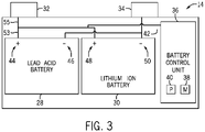
- the battery module 14 includes the first terminal 32, the second terminal 34, the lead acid battery 28, the lithium ion battery 30, and a battery control unit 36.
- the battery control unit 36 generally refers to control components that control operation of the battery system 12, such as relays within the battery module 14 or switches in the alternator 18.
- the operation of the battery module 14 may be controlled by the battery control unit 36,
- the battery control unit 36 is configured to regulate an amount of electrical energy captured/supplied by each battery 28 or 30 (e.g., to de-rate and re-rate the battery system 12), perform load balancing between the batteries, control charging and discharging of the batteries (e.g., via relays or DC/DC converters), determine a state of charge of each battery and/or the entire battery module 14, activate an active-cooling mechanism, activate a short circuit protection system, and the like.
- the battery control unit 36 may include one or more memory 38 and one or more processor 40 programmed to execute control algorithms for performing such tasks. More specifically, the one or more processor 40 may include one or more application specific integrated circuits (ASICs), one or more field programmable gate arrays (FPGAs), one or more general purpose processors, or any combination thereof. Additionally, the one or more memory 38 may include volatile memory, such as random access memory (RAM), and/or non-volatile memory, such as read-only memory (ROM), optical drives, hard disc drives, or solid-state drives. In some embodiments, the battery control unit 36 may include portions of a vehicle control unit (VCU) and/or a separate battery control module. Additionally, as depicted, the battery control unit 36 may be included separate from the battery module 14, such as a standalone module. In other embodiments, as depicted in FIG. 3 , the battery control unit 36 may be included within the battery module 14.
- VCU vehicle control unit
- the lead acid battery 28 and the lithium ion battery 30 are connected in parallel across the first terminal 32 and the second terminal 34 to enable charging and discharging of the batteries.
- the battery terminals 32 and 34 may output the power stored in the battery module 14 to provide power to the vehicle's electrical system. Further, the battery terminals 32 and 34 may also input power to the battery module 14 to enable the lead acid battery 28 and the lithium ion battery 30 to charge, for example, when the alternator 18 generates electrical power through regenerative braking.
- FIG. 3 illustrates a schematic view of components of the battery module 14.
- the lead acid battery 28 and the lithium ion battery 30 are separate within the battery module 14, which enables each to be configured based on desired characteristics, such as output voltage.
- the output voltage of the lead acid battery 28 and lithium ion battery 30 may depend on the configuration of individual battery cells within each battery (e.g., in serial or parallel) and the battery chemistries selected.
- the configuration of battery cells and the battery chemistries selected may result in certain advantages specific to multiple battery chemistries and cell arrangements. For example, the advantages may include an increased range in charging voltages, or the advantages may include varied power and charging capacities within the battery module 14.
- the lead acid battery 28 and the lithium ion battery 30 may couple to the first terminal 32 and the second terminal 34 in a parallel manner.
- a positive terminal 44 of the lead acid battery 28 may electrically couple to the first terminal 32 of the battery module 14, and a negative terminal 46 may electrically couple to the second terminal 34 of the battery module 14.
- a positive terminal 48 of the lithium ion battery 30 may electrically couple to the first terminal 32 of the battery module 14, and a negative terminal 50 of the lithium ion battery 30 may electrically couple to the second terminal 34 of the battery module 14.
- the two batteries 28, 30 may electrically couple in parallel with each other to the bus 26 to provide power to various components of the electrical system of the vehicle 10.
- the lead acid battery 28 and the lithium ion batter 30 are illustrated in FIG. 3 as being coupled in parallel with each other, it should be noted that the presently disclosed embodiments may be incorporated into any suitable battery system.
- the presently disclosed embodiments may be implemented in a high voltage system that does not connect the lead acid battery 28 in parallel with the lithium ion battery 30.
- the presently disclosed embodiments may be coupled to a single battery, a series of batteries, and the like.
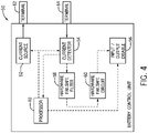
- FIG. 4 is a schematic diagram of the battery control unit 36 and various components that may be employed to monitor various properties of the battery control unit 36.
- the battery control unit 36 includes the processor 40, a current source 52, a current detector 54, an input/output disable component 56, a hardware failsafe filter 58, a hardware failsafe circuit 60, a terminal 62, and a terminal 64.
- the processor 40 as discussed above, may include any suitable processor capable of executing computer-executable instructions.
- the processor 40 sends a signal to the current source 52 indicating a pattern in which to activate and deactivate the current source 52.
- the current source 52 may include any suitable circuit that outputs some current (e.g., 10mA, 20mA).
- the processor 40 provides a current signal to the current source 52.
- the current signal specifies a pattern in which different current values are to be output by the current source 52.
- the current signal may indicate to the current source 52 to switch or alternate between a 10 mA current and a 20 mA current. Although this example corresponds to switching between two current values, it should be noted that the current signal may provide a pattern that switches between any suitable number of current values that the current source 52 may be capable of outputting.
- the current source 52 Upon receiving the activation pattern and the current signal from the processor 40, the current source 52 outputs a current that corresponds to the activation pattern and the current signal to the terminal 62.
- the terminal 62 may be a battery service disconnect, a high voltage connector, or other interface that may be coupled to a circuit or circuit components (e.g., electronic components) that the battery control unit 36 may monitor to prevent from being modified or accessed.
- the circuit components coupled to the terminal 62 and being monitored by the battery control unit 36 may include a service disconnect for the battery module, a high voltage (HV) direct-current (DC) link connector for the battery module, a motor control system HV DC link connector, and the like.
- HV high voltage
- DC direct-current
- the current output via the terminal 62 may be routed serially through the intervening circuits or circuit components to the terminal 64, which may also include a battery service disconnect, a high voltage connector, or other interface.
- the current received via the terminal 64 is provided to the current detector 54.
- the current detector 54 may be a circuit component that includes a switchable window current detector that may monitor the current received via the terminal 64.
- the current detector 54 may include a window detector switching function that is synchronized with the current signal provided to the current source 52 discussed above. As such, the current detector 54 monitors the switching of the current output by the current source 52 with respect to the current signal provided by the processor 40.
- the current detector 54 receives the activation pattern provided to the current source 52 from the processor 40. As such, the current detector 54 determines whether the current received via the terminal 64 matches the active and inactive states specified in the pattern. Additional details with regard to determining whether the received current corresponds to the current signal and the activation pattern will be discussed with reference to FIGS. 5-7 below.
- the current detector 54 may compare the activation pattern and the current signal to the received current and send a delta or difference signal to the processor 40.
- the delta signal may indicate the difference between the activation pattern and the current signal with respect to the received current.
- the delta signal may be used to determine whether there is a discrepancy between the activation pattern and the current signal with respect to the received current.
- the current detector 54 may provide the processor 40 a signal or representation of the current received via the terminal 64. In this case, the processor 40 may compare the activation pattern and the current signal, to the received current and determine the delta signal.
- the delta signal may be zero until the activation pattern does not match the current signal At this time, the delta signal may change from low to high (e.g., 1) to indicate that a difference between the activation pattern and the current signal is present.
- the output of the current detector 54 may be provided to the hardware failsafe filter 58.
- the hardware failsafe filter 58 may receive the delta signal from the current detector 54 and determine whether the delta signal indicates that an error is present for a period of time that is greater than some value (e.g., 50 ms). If the hardware failsafe filter 58 determines that the error is present for longer than the specified amount of time, the hardware failsafe filter 58 may send an indication of the error to the hardware failsafe circuit 60. If, however, the hardware failsafe filter 58 determines that the error is not present for longer than the specified amount of time, the hardware failsafe filter 58 may not perform any action. For instance, if the threshold is 50 ms, the hardware failsafe filter 58 may not perform any action unless the delta signal indicates that a difference between the activation pattern and the current signal is present for longer than 50 ms.
- the hardware failsafe circuit 60 may send a command to the input/output (I/O) disable component to disable the I/O components coupled to the battery control unit 36 or the like.
- the I/O disable component 56 may include an electrical switch that breaks an electrical connection or a connection path between one or more I/O components and the battery control unit 36.
- the processor compares the output of the current detector 54 with the activation pattern and the current signal sent to the current source 52 to determine whether the output of the current detector 54 corresponds to or matches the activation pattern and the current signal. If the output matches an expected output of the current detector 54, the processor 40 continues to monitor the received output from the current detector 54. If, however, the output does not match the expected output of the current detector 54, the processor 40 sends a command to the I/O disable component 56 to disable the I/O components coupled to the battery control unit 36 as discussed above. For example, if the monitored component is modified or accessed by some user, the current conducted serially through the component to the current detector 54 may be altered.
- the current detected by the current detector 54 may not match or correspond to the activation pattern and the current signal provided to the current source 52.
- the processor 40 may send a command to the I/O disable component 56 to disable the I/O components coupled to the battery control unit 36 as discussed above.
- the processor 40 may also determine whether output of the current detector 52 indicates that an error is present for a period of time that is greater than some value (e.g., 50 ms) and send the command to the I/O disable component 56 to disable the I/O components coupled to the battery control unit 36 when the error is present for longer than the period of time.
- some value e.g. 50 ms
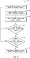
- FIG. 5 illustrates a flowchart of a method 80 that the processor 40 may use for monitoring properties of components coupled to the battery control unit 36 as described above.
- the method 80 may be performed by any suitable processor(s).
- the method 80 is described in a particular order, it should be understood that the method 80 may be performed in a variety of suitable orders.
- the processor 40 sends a command to the current source 52 to activate according to a source activation pattern signal.
- the source activation pattern which may be part of the command, is an asynchronous signal that indicates when the current source 52 should activate and deactivate.
- the source activation pattern corresponds to when the current source 52 outputs a current and when it does not output a current.
- the asynchronous signal may be randomly generated by the processor 40 using a random function or the like.
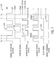
- FIG. 6 illustrates a collection of waveforms 100 that includes an example source activation pattern waveform 102 that indicates when the current source 52 will output current and when it will not output current.
- the processor 40 sends the current signal 104 to the current source 52.
- the current signal specifies a current value that the current source 52 should output.
- the current signal may be an asynchronous pattern.
- FIG. 6 includes an example current signal 104 that indicates when the current source 52 will output 10 mA and when it will output 20 mA.
- the processor 40 receives a current signal status from the current detector 54.
- the current signal status indicates the current detected by the current detector 54.
- FIG. 6 illustrates an example current signal status 106 waveform that may be detected by the current detector 54 based on the activation pattern waveform 102 and the current signal waveform 104. As shown in the current signal status 106, when the activation pattern waveform 102 is on at t1, the current signal status 106 indicates that 1.24 V has been detected by the current detector 54.
- the current detector 54 may include a 124-ohm resistor in series with the terminal 64. As such, the voltage across the resistor may indicate the current received via the current detector 54.
- the 1.24 V detected by the current detector 54 corresponds to a 10 mA current.
- the current signal 104 changes to cause the current source 52 to output 20 mA.
- the current signal status 106 may indicate that the voltage across the resistor is 2.48 V, which corresponds to 20 mA.
- the source activation pattern 102 may move to cause the current source 52 to deactivate or stop outputting the current.
- the current signal status 106 may indicate that there is 0 V or no current across the resistor within the current detector 54. That is, even though the current signal 104 indicates that the current source 52 should output 20 mA at time t3, since the activation pattern is off at time t3, the current source 52 may not output current, and thus the current detector 54 may not detect current.
- the processor 40 determines whether the current signal status 106 corresponds to an expected current signal status.
- the processor 40 may analyze the activation pattern 102 and the current signal 104 to determine an expected waveform for the current signal status 106.
- the processor 40 may determine whether current is detected by the current detector 52 in accordance with the activation pattern. For instance, the processor 40 may receive a current detect status signal 108 from the current detector 54. The current detect status signal 108 may indicate whether current is present across the resistor of the current detector 54 or not. As such, at block 88 of the method 80, the processor 40 may determine whether the current detect status signal 108 matches the source activation pattern 102.
- the processor 40 may return to block 82. If, however, the processor 40 determines that the current signal status does not match the expected status, the processor may proceed to block 90.
- the processor 40 may determine whether an error is present in the current detect status signal 108 for more than a threshold amount or period of time (e.g., 50 ms). That is, the processor 40 may determine whether the current signal status 106 or the current detect status signal 108 does not match the expected current signal status for more than the threshold amount of time. If the error is not present for less than the threshold amount of time, the processor 40 may return to block 82.
- a threshold amount or period of time e.g. 50 ms
- the processor 40 may proceed to block 92 and send a disable signal to the I/O disable component 56.
- the I/O disable component 56 may open a circuit or disconnect devices coupled to the battery control unit 36 via the terminals 62 and 64, as discussed above.
- FIG. 7 illustrates a sample current signal status 122 that does not match the expected status waveform. That is, according to the source activation pattern 102 and the current signal 104, the current detector 54 should detect a 20 mA current at time t5. However, as shown in the current signal status 122, at time t5, the current signal status 122 still indicates that a 10 mA current is present. As a result, a delta signal 124 may indicate that an error is present at time t5.
- the processor 40 may proceed to block 90 and determine whether the error is present for more than the threshold amount of time. As shown in an error confirmed signal 126 in FIG. 7 , the error present in the delta signal 124 at time t5 is not present for more than the threshold period of time. However, at time t7, the delta signal 124 may be present for more than the threshold amount of time (e.g., 50 ms). As a result, the error confirmed signal 126 may become active at time t8 when the delta signal is present for longer than the threshold amount of time Referring back to block 90 and FIG. 7 , at time t8, the processor 40 may proceed to block 92 and send the disable signal to the I/O disable component.
- the threshold amount of time e.g. 50 ms
- the processor 40 may proceed directly to block 92 when the processor 40 detects the error in the delta signal 124.
- the processor 40 may generate an alarm, send a notification, or provide some other notice to a user when it detects the error in the delta signal 124.
- the hardware failsafe filter 58 may receive the delta signal from the current detector 54 and determine whether the delta signal indicates that an error is present and/or determine whether the delta signal indicates that an error is present for a period of time that is greater than some value (e.g., 50 ms).
- the hardware failsafe filter 58 may send an indication of the error to the hardware failsafe circuit 60, which may send a command to the input/output (I/O) disable component to disable the I/O components coupled to the battery control unit 36 or the like. In this way, the hardware failsafe filter 58 may disable the I/O components coupled to the battery control unit 36 regardless of the operation of the processor 40. As such, the hardware components may serve as an additional safeguard to ensure that the I/O components are disabled when the battery control unit 36 or the battery module may be compromised.
- I/O input/output
- the presently disclosed embodiments may further protect the battery module from being manipulated via compromises to the operation of the processor 40. That is, the hardware components described herein may provide a redundant or independent option for protecting the I/O components.
- One or more of the disclosed embodiments may provide one or more technical effects including preventing the modification of the battery control unit 36, the battery module 14, and the like.
- the systems and methods described herein may be alerted with regard to when a component is being access or altered and may then disable the respective component. As a result, the integrity of the component and the battery module 14 itself may be preserved.
- the technical effects and technical problems in the specification are exemplary and are not limiting. It should be noted that the embodiments described in the specification may have other technical effects and can solve other technical problems.
Landscapes
- Engineering & Computer Science (AREA)
- Power Engineering (AREA)
- Life Sciences & Earth Sciences (AREA)
- Sustainable Development (AREA)
- Sustainable Energy (AREA)
- Transportation (AREA)
- Mechanical Engineering (AREA)
- Manufacturing & Machinery (AREA)
- Chemical & Material Sciences (AREA)
- Chemical Kinetics & Catalysis (AREA)
- Electrochemistry (AREA)
- General Chemical & Material Sciences (AREA)
- Microelectronics & Electronic Packaging (AREA)
- Physics & Mathematics (AREA)
- General Physics & Mathematics (AREA)
- Secondary Cells (AREA)
- Charge And Discharge Circuits For Batteries Or The Like (AREA)
Description
- This application claims priority from
U.S. Provisional Application Serial No. 62/291,096, entitled "SAFETY INTERLOCK UTILIZING AN ASYNCHRONOUS CURRENT SOURCE", filed February 4, 2016 - The present disclosure generally relates to the field of batteries and battery modules. More specifically, the present disclosure relates to an integrated battery safety interlock to prevent the modification of a battery module.
- This section is intended to introduce the reader to various aspects of art that may be related to various aspects of the present disclosure, which are described below. This discussion is believed to be helpful in providing the reader with background information to facilitate a better understanding of the various aspects of the present disclosure. Accordingly, it should be understood that these statements are to be read in this light, and not as admissions of prior art.
- A vehicle that uses one or more battery systems for providing all or a portion of the motive power for the vehicle can be referred to as an xEV, where the term "xEV" is defined herein to include all of the following vehicles, or any variations or combinations thereof, that use electric power for all or a portion of their vehicular motive force. For example, xEVs include electric vehicles (EVs) that utilize electric power for all motive force. As will be appreciated by those skilled in the art, hybrid electric vehicles (HEVs), also considered xEVs, combine an internal combustion engine propulsion system and a battery-powered electric propulsion system, such as 48 volt or 130 volt systems. The term HEV may include any variation of a hybrid electric vehicle.
- For example, fill hybrid systems (FHEVs) may provide motive and other electrical power to the vehicle using one or more electric motors, using only an internal combustion engine, or using both. In contrast, mild hybrid systems (MHEVs) disable the internal combustion engine when the vehicle is idling and utilize a battery system to continue powering the air conditioning unit, radio, or other electronics, as well as to restart the engine when propulsion is desired. The mild hybrid system may also apply some level of power assist, during acceleration for example, to supplement the internal combustion engine. Mild hybrids are typically 96V to 130V and recover braking energy through a belt or crank integrated starter generator.
- Further, a micro-hybrid electric vehicle (mHEV) also uses a "Stop-Start" system similar to the mild hybrids, but the micro-hybrid systems of an mHEV may or may not supply power assist to the internal combustion engine and operates at a voltage below 60V. For the purposes of the present discussion, it should be noted that mHEVs typically do not technically use electric power provided directly to the crankshaft or transmission for any portion of the motive force of the vehicle, but an mHEV may still be considered as an xEV since it does use electric power to supplement a vehicle's power needs when the vehicle is idling with internal combustion engine disabled and recovers braking energy through an integrated starter generator. In addition, a plug-in electric vehicle (PEV) is any vehicle that can be charged from an external source of electricity, such as wall sockets, and the energy stored in the rechargeable battery packs drives or contributes to drive the wheels. PEVs are a subcategory of EVs that include all-electric or battery electric vehicles (BEVs), plug-in hybrid electric vehicles (PHEVs), and electric vehicle conversions of hybrid electric vehicles and conventional internal combustion engine vehicles.
- xEVs as described above may provide a number of advantages as compared to more traditional gas-powered vehicles using only internal combustion engines and traditional electrical systems, which are typically 12V systems powered by a lead acid battery. For example, xEVs may produce fewer undesirable emission products and may exhibit greater fuel efficiency as compared to traditional internal combustion vehicles and, in some cases, such xEVs may eliminate the use of gasoline entirely, as is the case of certain types of EVs or PEVs.
-
US 2016/018471 A1 relates to a battery system identification through impulse injection for vehicle systems. The vehicle systems can include a traction battery and a controller to operate the traction battery according to current limits of a battery model identified from a battery response to a pulse of current injected into the battery while the battery is not being discharged to propel the vehicle or being charged. The controller can implement a state estimator configured to output battery state using a battery impulse response. -
US 2003/206021 A1 relates to a method and apparatus for measuring and analyzing electrical or electrochemical systems comprising creating a time-varying electrical excitation, delivering the same to a system comprising at least one electronic or electrochemical element and measuring and analyzing a time-varying electrical response developed within the system in response to the excitation. The response signal and the excitation signal are sampled in a synchronous manner, and the sampled values are analyzed to determine various characteristics of the system. -
CN 104377684 A discloses an example of interlocking circuit for high-voltage parts in electric cars. - Given that battery modules are used to provide power to these vehicles, the battery modules are integral to the operation of these vehicles. As such, it may be useful to prevent the battery module from being modified. Accordingly, it may be useful to employ circuitry that monitors various properties of the battery modules and components coupled to the battery modules.
- The invention is defined by the appended claims.
- Various aspects of this disclosure may be better understood upon reading the following detailed description and upon reference to the drawings in which:
-
FIG. 1 is perspective view of a vehicle (e.g., an xEV) having a battery system contributing all or a portion of the power for the vehicle, in accordance with an embodiment presented herein; -
FIG. 2 is a cutaway schematic view of the vehicle ofFIG. 1 in the form of a hybrid electric vehicle (HEV), in accordance with an embodiment presented herein; -
FIG. 3 is a schematic view of a battery system with a first battery, a second battery, and a battery control unit, in accordance with an embodiment presented herein; -
FIG. 4 is a schematic diagram of a battery control unit of the battery system ofFIG. 3 , in accordance with an embodiment presented herein; -
FIG. 5 is a flow chart describing a method for monitoring properties of the battery system ofFIG. 3 , in accordance with an embodiment presented herein; -
FIG. 6 includes example waveforms depicting the states of various components within the battery control unit ofFIG. 4 while operating under normal conditions, in accordance with an embodiment presented herein; and -
FIG. 7 includes example waveforms depicting the states of various components within the battery control unit ofFIG. 4 when an error is present, in accordance with an embodiment presented herein. - One or more specific embodiments will be described below. In an effort to provide a concise description of these embodiments, not all features of an actual implementation are described in the specification. It should be appreciated that in the development of any such actual implementation, as in any engineering or design project, numerous implementation-specific decisions must be made to achieve the developers' specific goals, such as compliance with system-related and business-related constraints, which may vary from one implementation to another. Moreover, it should be appreciated that such a development effort might be complex and time consuming, but would nevertheless be a routine undertaking of design, fabrication, and manufacture for those of ordinary skill having the benefit of this disclosure.
- The present disclosure relates to batteries and battery modules. More specifically, the present disclosure relates to interlocking a battery module using an asynchronous current source, thereby preventing unauthorized modification or access to the battery module.
- Generally, a vehicle may include a battery system to provide motive force for the vehicle. As such, the battery system may include a number of battery modules, such as a lithium-ion battery module, a lead-acid battery module, and the like. In one embodiment, the lithium-ion battery module may include circuitry that monitors the SOH and SOC of each of a number of lithium ion cells of the lithium ion battery module, as well as a number of other properties related to the lithium ion battery module. In addition to monitoring the properties of the lithium ion battery module, the circuitry may also monitor various aspects of the lead acid battery module, which may be coupled in series with the lithium ion battery module at one terminal.
- To effectively monitor the integrity of the battery module, a battery control unit within the battery module may asynchronously activate and deactivate a current source that outputs current through one terminal of the battery module and receives the same current via another terminal of the battery module. In one embodiment, that battery control unit may monitor the current received via the other terminal and compare the received current signal with a pattern in which the current source has been activated and deactivated. If the battery control unit detects a discrepancy between the received current signal and the pattern of activation of the current source, the battery control unit may disable components coupled to the battery control unit. As a result, the battery control unit may detect attempts to modify or alter the battery module and disconnect the battery module from other components to prevent the alteration of the operation of the battery module.
- In one embodiment, the battery control unit may serve as an interlock for improved quality of service for personnel in high voltage (HV) applications (e.g., ≥60V). As such, the circuits being protected by the interlock may routed through the external connections of the battery module, and the battery control unit may monitor the integrity of those connections. For example, if a service technician removes a high voltage bus or other connector while the vehicle/system is energized, the battery control unit may automatically disconnect the HV battery from the external bus connections via contactors. Additional details with regard to monitoring the battery module will be discussed below with reference to
FIGS. 1-7 . - In addition to monitoring the battery module, as discussed above, the battery control unit may also be employed to control the operation of various types of batteries for use in vehicle systems. For instance, the vehicle system may include a battery xEV vehicle systems, which may provide advantages over traditional gas-powered vehicle technology. Further, battery xEV technology has led to improvements in fuel economy and/or reductions in undesirable emissions compared to more traditional gas-powered vehicles. For example, regenerative braking vehicles capture and store electrical energy generated when the vehicle is braking or coasting. The captured electrical energy may then be utilized to supply power to the vehicle's electrical system. As another example, battery modules in accordance with present embodiments may be incorporated with or provide power to stationary power systems (e.g., non-automotive systems).
- Based on the advantages over traditional gas-powered vehicles, manufacturers, which generally produce traditional gas-powered vehicles, may desire to utilize improved vehicle technologies (e.g., regenerative braking technology) within their vehicle lines. Often, these manufacturers may utilize one of their traditional vehicle platforms as a starting point. Accordingly, since traditional gas-powered vehicles are designed to utilize 12-volt battery systems, a 12-volt lithium ion battery may be used to supplement a 12-volt lead-acid battery. More specifically, the 12-volt lithium ion battery may be used to more efficiently capture electrical energy generated during regenerative braking and subsequently supply electrical energy to power the vehicle's electrical system.
- However, as advancements occur with vehicle technologies, high voltage electrical devices may be included in the vehicle's electrical system. For example, the lithium ion battery may supply electrical energy to an electric motor in a mild-hybrid vehicle. Often, these high voltage electrical devices utilize voltage greater than 12 volts, for example, up to 48 volts. Accordingly, in some embodiments, the output voltage of a 12-volt lithium ion battery may be boosted using a DC-DC converter to supply power to the high voltage devices. Additionally or alternatively, a 48-volt lithium ion battery may be used to supplement a 12-volt lead-acid battery. More specifically, the 48-volt lithium ion battery may be used to more efficiently capture electrical energy generated during regenerative braking and subsequently supply electrical energy to power the high voltage devices.
- Thus, the design choice regarding whether to utilize a 12-volt lithium ion battery or a 48-volt lithium ion battery may depend directly on the electrical devices included in a particular vehicle. Nevertheless, although the voltage characteristics may differ, the operational principles of a 12-volt lithium ion battery and a 48-voltlithium ion battery are generally similar. More specifically, as described above, both may be used to capture electrical energy during regenerative braking and subsequently supply electrical energy to power electrical devices in the vehicle.
- Accordingly, to simplify the following discussion, the present techniques will be described in relation to a battery system with a 12-volt lithium ion battery and a 12-volt lead-acid battery. However, one of ordinary skill in art should be able to adapt the present techniques to other battery systems, such as a battery system with a 48-volt lithium ion battery and a 12-volt lead-acid battery or any other suitable combination of batteries.
- With the preceding in mind, the present disclosure describes systems and techniques for monitoring properties of the battery module. By way of introduction,
FIG. 1 is a perspective view of an embodiment of avehicle 10, which may utilize a regenerative braking system. Although the following discussion is presented in relation to vehicles with regenerative braking systems, the techniques described herein may be applied to other vehicles including xEV and gas-powered vehicles. - As discussed above, it would be desirable for a
battery system 12 to be largely compatibie with traditional vehicle designs. Accordingly, thebattery system 12 may be placed in a location in thevehicle 10 that would have housed a traditional battery system. For example, as illustrated, thevehicle 10 may include thebattery system 12 positioned similarly to a lead-acid battery of a typical combustion-engine vehicle (e.g., under the hood of the vehicle 10). Furthermore, as will be described in more detail below, thebattery system 12 may be positioned to facilitate managing temperature of thebattery system 12. For example, in some embodiments, positioning abattery system 12 under the hood of thevehicle 10 may enable an air duct to channel airflow over thebattery system 1 2 and cool thebattery system 12. - A more detailed view of the
battery system 12 is described inFIG. 2 . As depicted, thebattery system 12 includesbattery module 14 coupled to anignition system 16, analternator 18, avehicle console 20, and optionally to anelectric motor 22. Generally, thebattery module 14 may capture/store electrical energy generated in thevehicle 10 and output electrical energy to power electrical devices in thevehicle 10. - More specifically, the
battery module 14 may capture/store generated electrical energy and output electrical energy to power each of these components, as well as others. In other words, thebattery system 12 may supply power to components of the vehicle's electrical system, which may include radiator cooling fans, climate control systems, electric power steering systems, active suspension systems, auto park systems, electric oil pumps, electric super/turbochargers, electric water pumps, heated windscreen/defrosters, window lift motors, vanity lights, tire pressure monitoring systems, sunroof motor controls, power seats, alarm systems, infotainment systems, navigation features, lane departure warning systems, electric parking brakes, external lights, or any combination thereof. Illustratively, thebatter module 14 depicted inFIG. 2 supplies power to thevehicle console 20 and theignition system 16 to start (e.g., crank) theinternal combustion engine 24. In some embodiments, theignition system 16 may include a traditional starter and/or a belt starter generator (BSG). - Additionally, the
battery module 14 may capture electrical energy generated by thealternator 18 and/or theelectric motor 22. In some embodiments, thealternator 18 may generate electrical energy while theinternal combustion engine 24 is running. More specifically, thealternator 18 may convert the mechanical energy produced by the rotation of theinternal combustion engine 24 into electrical energy. Additionally or alternatively, when thevehicle 10 includes anelectric motor 22, theelectric motor 22 may generate electrical energy by converting mechanical energy produced by the movement of the vehicle 10 (e.g., rotation of the wheels) into electrical energy. In other words, thebattery module 14 may capture electrical energy generated during regenerative braking. - To facilitate capturing and supplying electric energy, the
battery module 14 may be coupled to the vehicle's electric system via abus 26. For example, thebus 26 may enable thebattery module 14 to receive electrical energy generated by thealternator 18 and/or theelectric motor 22. Additionally, thebus 26 may enable thebattery module 14 to output electrical energy to theignition system 16 and/or thevehicle console 20. Accordingly, when a 12-volt battery system 12 is used, thebus 26 may carry electrical power typically between 8-18 volts. - Additionally, the
battery module 14 may include multiple battery modules. For example, in the depicted embodiment, thebattery module 14 includes alead acid battery 28 and alithium ion battery 30, which each includes one or more battery cells. In other embodiments, thebattery module 14 may include any number of battery modules. Additionally, although thelead acid battery 28 and thelithium ion battery 30 are depicted adjacent to one another, they may be positioned in different areas around the vehicle. For example, thelithium ion battery 30 may be positioned in or about the interior of thevehicle 10 while thelead acid battery 28 may be positioned under the hood of thevehicle 10. - By employing the
lead acid battery 28 with the lithium,ion battery 30, the performance of thebattery system 12 may be improved since the lithium ion battery chemistry generally has a higher coulombic efficiency and/or a higher power charge acceptance rate (e.g., higher maximum charge current or charge voltage) than the lead-acid battery chemistry. As such, the capture, storage, and/or distribution efficiency of thebattery system 12 may be improved. - To facilitate supply of power from the
battery system 12 to the various components in the vehicle's electrical system (e.g., HVAC system and vehicle console 20), thebattery module 14 includes afirst terminal 32 and asecond terminal 34. In some embodiments, thesecond terminal 34 may provide a ground connection and thefirst terminal 32 may provide a positive voltage ranging between 7-18 volts. A more detailed view of an embodiment of thebattery module 14 is depicted inFIG. 3 . As previously noted, thebattery module 14 may have dimensions comparable to those of a typical lead-acid battery to limit medications to thevehicle 10 design to accommodate thebattery system 12. For example, thebattery module 14 may be of similar dimensions to an H6 battery, which may be approximately 13.9 inches × 6.8 inches × 7.5 inches. As depicted, thebattery module 14 may be included within a single continuous housing. In other embodiments, thebattery module 14 may include multiple housings coupled together (e.g., a first housing including thelead acid battery 28 and a second housing including the lithium ion battery 30). In still other embodiments, as mentioned above thebattery module 14 may include thelead acid battery 28 located under the hood of thevehicle 10, and thelithium ion battery 30 may be located within the interior of thevehicle 10. - As depicted, the
battery module 14 includes thefirst terminal 32, thesecond terminal 34, thelead acid battery 28, thelithium ion battery 30, and abattery control unit 36. As used herein, thebattery control unit 36 generally refers to control components that control operation of thebattery system 12, such as relays within thebattery module 14 or switches in thealternator 18. The operation of thebattery module 14 may be controlled by thebattery control unit 36, For example, thebattery control unit 36 is configured to regulate an amount of electrical energy captured/supplied by eachbattery 28 or 30 (e.g., to de-rate and re-rate the battery system 12), perform load balancing between the batteries, control charging and discharging of the batteries (e.g., via relays or DC/DC converters), determine a state of charge of each battery and/or theentire battery module 14, activate an active-cooling mechanism, activate a short circuit protection system, and the like. - Accordingly, the
battery control unit 36 may include one ormore memory 38 and one ormore processor 40 programmed to execute control algorithms for performing such tasks. More specifically, the one ormore processor 40 may include one or more application specific integrated circuits (ASICs), one or more field programmable gate arrays (FPGAs), one or more general purpose processors, or any combination thereof. Additionally, the one ormore memory 38 may include volatile memory, such as random access memory (RAM), and/or non-volatile memory, such as read-only memory (ROM), optical drives, hard disc drives, or solid-state drives. In some embodiments, thebattery control unit 36 may include portions of a vehicle control unit (VCU) and/or a separate battery control module. Additionally, as depicted, thebattery control unit 36 may be included separate from thebattery module 14, such as a standalone module. In other embodiments, as depicted inFIG. 3 , thebattery control unit 36 may be included within thebattery module 14. - Additionally, as depicted in
FIG. 2 , thelead acid battery 28 and thelithium ion battery 30 are connected in parallel across thefirst terminal 32 and thesecond terminal 34 to enable charging and discharging of the batteries. As described above, thebattery terminals battery module 14 to provide power to the vehicle's electrical system. Further, thebattery terminals battery module 14 to enable thelead acid battery 28 and thelithium ion battery 30 to charge, for example, when thealternator 18 generates electrical power through regenerative braking. - To provide more detail as to the
battery module 14,FIG. 3 illustrates a schematic view of components of thebattery module 14. As depicted, thelead acid battery 28 and thelithium ion battery 30 are separate within thebattery module 14, which enables each to be configured based on desired characteristics, such as output voltage. For example, the output voltage of thelead acid battery 28 andlithium ion battery 30 may depend on the configuration of individual battery cells within each battery (e.g., in serial or parallel) and the battery chemistries selected. Further, the configuration of battery cells and the battery chemistries selected may result in certain advantages specific to multiple battery chemistries and cell arrangements. For example, the advantages may include an increased range in charging voltages, or the advantages may include varied power and charging capacities within thebattery module 14. - Additionally, as discussed above and shown in
FIG. 3 , thelead acid battery 28 and thelithium ion battery 30 may couple to thefirst terminal 32 and thesecond terminal 34 in a parallel manner. In other words, apositive terminal 44 of thelead acid battery 28 may electrically couple to thefirst terminal 32 of thebattery module 14, and anegative terminal 46 may electrically couple to thesecond terminal 34 of thebattery module 14. In a similar manner, apositive terminal 48 of thelithium ion battery 30 may electrically couple to thefirst terminal 32 of thebattery module 14, and anegative terminal 50 of thelithium ion battery 30 may electrically couple to thesecond terminal 34 of thebattery module 14. In this manner, the twobatteries bus 26 to provide power to various components of the electrical system of thevehicle 10. - Although the
lead acid battery 28 and thelithium ion batter 30 are illustrated inFIG. 3 as being coupled in parallel with each other, it should be noted that the presently disclosed embodiments may be incorporated into any suitable battery system. For instance, the presently disclosed embodiments may be implemented in a high voltage system that does not connect thelead acid battery 28 in parallel with thelithium ion battery 30. Instead, the presently disclosed embodiments may be coupled to a single battery, a series of batteries, and the like. - With the foregoing in mind,
FIG. 4 is a schematic diagram of thebattery control unit 36 and various components that may be employed to monitor various properties of thebattery control unit 36. As shown inFIG. 4 , thebattery control unit 36 includes theprocessor 40, acurrent source 52, acurrent detector 54, an input/output disablecomponent 56, a hardwarefailsafe filter 58, a hardwarefailsafe circuit 60, a terminal 62, and a terminal 64. Theprocessor 40, as discussed above, may include any suitable processor capable of executing computer-executable instructions. - The
processor 40 sends a signal to thecurrent source 52 indicating a pattern in which to activate and deactivate thecurrent source 52. As such, thecurrent source 52 may include any suitable circuit that outputs some current (e.g., 10mA, 20mA). In addition to providing the activation pattern to thecurrent source 52, theprocessor 40 provides a current signal to thecurrent source 52. The current signal specifies a pattern in which different current values are to be output by thecurrent source 52. For example, the current signal may indicate to thecurrent source 52 to switch or alternate between a 10 mA current and a 20 mA current. Although this example corresponds to switching between two current values, it should be noted that the current signal may provide a pattern that switches between any suitable number of current values that thecurrent source 52 may be capable of outputting. - Upon receiving the activation pattern and the current signal from the
processor 40, thecurrent source 52 outputs a current that corresponds to the activation pattern and the current signal to the terminal 62. The terminal 62 may be a battery service disconnect, a high voltage connector, or other interface that may be coupled to a circuit or circuit components (e.g., electronic components) that thebattery control unit 36 may monitor to prevent from being modified or accessed. By way of example, the circuit components coupled to the terminal 62 and being monitored by thebattery control unit 36 may include a service disconnect for the battery module, a high voltage (HV) direct-current (DC) link connector for the battery module, a motor control system HV DC link connector, and the like. - The current output via the terminal 62 may be routed serially through the intervening circuits or circuit components to the terminal 64, which may also include a battery service disconnect, a high voltage connector, or other interface. The current received via the terminal 64 is provided to the
current detector 54. Thecurrent detector 54 may be a circuit component that includes a switchable window current detector that may monitor the current received via theterminal 64. In one embodiment, thecurrent detector 54 may include a window detector switching function that is synchronized with the current signal provided to thecurrent source 52 discussed above. As such, thecurrent detector 54 monitors the switching of the current output by thecurrent source 52 with respect to the current signal provided by theprocessor 40. - In addition to the current signal, the
current detector 54 receives the activation pattern provided to thecurrent source 52 from theprocessor 40. As such, thecurrent detector 54 determines whether the current received via the terminal 64 matches the active and inactive states specified in the pattern. Additional details with regard to determining whether the received current corresponds to the current signal and the activation pattern will be discussed with reference toFIGS. 5-7 below. - In some embodiments, the
current detector 54 may compare the activation pattern and the current signal to the received current and send a delta or difference signal to theprocessor 40. The delta signal may indicate the difference between the activation pattern and the current signal with respect to the received current. As such, the delta signal may be used to determine whether there is a discrepancy between the activation pattern and the current signal with respect to the received current. In other embodiments, thecurrent detector 54 may provide the processor 40 a signal or representation of the current received via theterminal 64. In this case, theprocessor 40 may compare the activation pattern and the current signal, to the received current and determine the delta signal. For instance, if the activation pattern matches the current signal, the delta signal may be zero until the activation pattern does not match the current signal At this time, the delta signal may change from low to high (e.g., 1) to indicate that a difference between the activation pattern and the current signal is present. - In either situation, the output of the
current detector 54 may be provided to the hardwarefailsafe filter 58. The hardwarefailsafe filter 58 may receive the delta signal from thecurrent detector 54 and determine whether the delta signal indicates that an error is present for a period of time that is greater than some value (e.g., 50 ms). If the hardwarefailsafe filter 58 determines that the error is present for longer than the specified amount of time, the hardwarefailsafe filter 58 may send an indication of the error to the hardwarefailsafe circuit 60. If, however, the hardwarefailsafe filter 58 determines that the error is not present for longer than the specified amount of time, the hardwarefailsafe filter 58 may not perform any action. For instance, if the threshold is 50 ms, the hardwarefailsafe filter 58 may not perform any action unless the delta signal indicates that a difference between the activation pattern and the current signal is present for longer than 50 ms. - When the hardware
failsafe circuit 60 receives the indication of the error, the hardwarefailsafe circuit 60 may send a command to the input/output (I/O) disable component to disable the I/O components coupled to thebattery control unit 36 or the like. In one embodiment, the I/O disablecomponent 56 may include an electrical switch that breaks an electrical connection or a connection path between one or more I/O components and thebattery control unit 36. Although thecurrent detector 54, the I/O disablecomponent 56, the hardwarefailsafe filter 58, and the hardwarefailsafe circuit 60 are described herein as individual components, it should be noted that, in some embodiments, two or more of these components may be incorporated together within a single circuit. - Referring back to the
processor 40, in the invention the processor compares the output of thecurrent detector 54 with the activation pattern and the current signal sent to thecurrent source 52 to determine whether the output of thecurrent detector 54 corresponds to or matches the activation pattern and the current signal. If the output matches an expected output of thecurrent detector 54, theprocessor 40 continues to monitor the received output from thecurrent detector 54. If, however, the output does not match the expected output of thecurrent detector 54, theprocessor 40 sends a command to the I/O disablecomponent 56 to disable the I/O components coupled to thebattery control unit 36 as discussed above. For example, if the monitored component is modified or accessed by some user, the current conducted serially through the component to thecurrent detector 54 may be altered. As such, the current detected by thecurrent detector 54 may not match or correspond to the activation pattern and the current signal provided to thecurrent source 52. In this case, upon determining that the current detected by thecurrent detector 54 may not match or correspond to the activation pattern and the current signal provided to thecurrent source 52, theprocessor 40 may send a command to the I/O disablecomponent 56 to disable the I/O components coupled to thebattery control unit 36 as discussed above. - In the same manner as the hardware
failsafe filter 58, theprocessor 40 may also determine whether output of thecurrent detector 52 indicates that an error is present for a period of time that is greater than some value (e.g., 50 ms) and send the command to the I/O disablecomponent 56 to disable the I/O components coupled to thebattery control unit 36 when the error is present for longer than the period of time. - With the foregoing in mind,
FIG. 5 illustrates a flowchart of amethod 80 that theprocessor 40 may use for monitoring properties of components coupled to thebattery control unit 36 as described above. Although the following description of themethod 80 is described as being performed by theprocessor 40, it should be noted that themethod 80 may be performed by any suitable processor(s). In addition, although themethod 80 is described in a particular order, it should be understood that themethod 80 may be performed in a variety of suitable orders. - Referring now to
FIG. 5 , atblock 82, theprocessor 40 sends a command to thecurrent source 52 to activate according to a source activation pattern signal. The source activation pattern, which may be part of the command, is an asynchronous signal that indicates when thecurrent source 52 should activate and deactivate. In other words, the source activation pattern corresponds to when thecurrent source 52 outputs a current and when it does not output a current. In one embodiment, the asynchronous signal may be randomly generated by theprocessor 40 using a random function or the like.FIG. 6 illustrates a collection ofwaveforms 100 that includes an example sourceactivation pattern waveform 102 that indicates when thecurrent source 52 will output current and when it will not output current. - In addition to the source activation pattern, at
block 84, theprocessor 40 sends thecurrent signal 104 to thecurrent source 52. As discussed above, the current signal specifies a current value that thecurrent source 52 should output. Like the source activation pattern, the current signal may be an asynchronous pattern.FIG. 6 includes an examplecurrent signal 104 that indicates when thecurrent source 52will output 10 mA and when it willoutput 20 mA. - At
block 86, theprocessor 40 receives a current signal status from thecurrent detector 54. The current signal status indicates the current detected by thecurrent detector 54.FIG. 6 illustrates an examplecurrent signal status 106 waveform that may be detected by thecurrent detector 54 based on theactivation pattern waveform 102 and thecurrent signal waveform 104. As shown in thecurrent signal status 106, when theactivation pattern waveform 102 is on at t1, thecurrent signal status 106 indicates that 1.24 V has been detected by thecurrent detector 54. In one embodiment, thecurrent detector 54 may include a 124-ohm resistor in series with the terminal 64. As such, the voltage across the resistor may indicate the current received via thecurrent detector 54. That is, the 1.24 V detected by thecurrent detector 54 corresponds to a 10 mA current. At time t2, thecurrent signal 104 changes to cause thecurrent source 52 tooutput 20 mA. As such, thecurrent signal status 106 may indicate that the voltage across the resistor is 2.48 V, which corresponds to 20 mA. - At time t3, however, the
source activation pattern 102 may move to cause thecurrent source 52 to deactivate or stop outputting the current. As such, at time t3, thecurrent signal status 106 may indicate that there is 0 V or no current across the resistor within thecurrent detector 54. That is, even though thecurrent signal 104 indicates that thecurrent source 52 shouldoutput 20 mA at time t3, since the activation pattern is off at time t3, thecurrent source 52 may not output current, and thus thecurrent detector 54 may not detect current. - Referring back to
FIG. 5 , atblock 88, theprocessor 40 determines whether thecurrent signal status 106 corresponds to an expected current signal status. In one embodiment, theprocessor 40 may analyze theactivation pattern 102 and thecurrent signal 104 to determine an expected waveform for thecurrent signal status 106. - In another embodiment, the
processor 40 may determine whether current is detected by thecurrent detector 52 in accordance with the activation pattern. For instance, theprocessor 40 may receive a current detect status signal 108 from thecurrent detector 54. The current detect status signal 108 may indicate whether current is present across the resistor of thecurrent detector 54 or not. As such, atblock 88 of themethod 80, theprocessor 40 may determine whether the current detect status signal 108 matches thesource activation pattern 102. - If, at
block 88, theprocessor 40 determines that the current signal status matches the expected status, theprocessor 40 may return to block 82. If, however, theprocessor 40 determines that the current signal status does not match the expected status, the processor may proceed to block 90. Atblock 90, theprocessor 40 may determine whether an error is present in the current detect status signal 108 for more than a threshold amount or period of time (e.g., 50 ms). That is, theprocessor 40 may determine whether thecurrent signal status 106 or the current detectstatus signal 108 does not match the expected current signal status for more than the threshold amount of time. If the error is not present for less than the threshold amount of time, theprocessor 40 may return to block 82. - If the error is present for more than the threshold amount of time, the
processor 40 may proceed to block 92 and send a disable signal to the I/O disablecomponent 56. As such, the I/O disablecomponent 56 may open a circuit or disconnect devices coupled to thebattery control unit 36 via theterminals - Referring back to block 88,
FIG. 7 illustrates a samplecurrent signal status 122 that does not match the expected status waveform. That is, according to thesource activation pattern 102 and thecurrent signal 104, thecurrent detector 54 should detect a 20 mA current at time t5. However, as shown in thecurrent signal status 122, at time t5, thecurrent signal status 122 still indicates that a 10 mA current is present. As a result, adelta signal 124 may indicate that an error is present at time t5. - As discussed above, after the
processor 40 detects the error in thedelta signal 124 atblock 88, theprocessor 40 may proceed to block 90 and determine whether the error is present for more than the threshold amount of time. As shown in an error confirmedsignal 126 inFIG. 7 , the error present in thedelta signal 124 at time t5 is not present for more than the threshold period of time. However, at time t7, thedelta signal 124 may be present for more than the threshold amount of time (e.g., 50 ms). As a result, the error confirmedsignal 126 may become active at time t8 when the delta signal is present for longer than the threshold amount of time Referring back to block 90 andFIG. 7 , at time t8, theprocessor 40 may proceed to block 92 and send the disable signal to the I/O disable component. - Referring back to block 88, in certain embodiments, the
processor 40 may proceed directly to block 92 when theprocessor 40 detects the error in thedelta signal 124. In another embodiment, theprocessor 40 may generate an alarm, send a notification, or provide some other notice to a user when it detects the error in thedelta signal 124. In this case, the hardwarefailsafe filter 58 may receive the delta signal from thecurrent detector 54 and determine whether the delta signal indicates that an error is present and/or determine whether the delta signal indicates that an error is present for a period of time that is greater than some value (e.g., 50 ms). If both conditions are present, the hardwarefailsafe filter 58 may send an indication of the error to the hardwarefailsafe circuit 60, which may send a command to the input/output (I/O) disable component to disable the I/O components coupled to thebattery control unit 36 or the like. In this way, the hardwarefailsafe filter 58 may disable the I/O components coupled to thebattery control unit 36 regardless of the operation of theprocessor 40. As such, the hardware components may serve as an additional safeguard to ensure that the I/O components are disabled when thebattery control unit 36 or the battery module may be compromised. - By employing the hardware
failsafe filter 58 and the hardwarefailsafe circuit 60 to disable the I/O components independently of the operations of theprocessor 40, the presently disclosed embodiments may further protect the battery module from being manipulated via compromises to the operation of theprocessor 40. That is, the hardware components described herein may provide a redundant or independent option for protecting the I/O components. - One or more of the disclosed embodiments, alone or in combination, may provide one or more technical effects including preventing the modification of the
battery control unit 36, thebattery module 14, and the like. In particular, by providing an asynchronous current signal serially through protected components, the systems and methods described herein may be alerted with regard to when a component is being access or altered and may then disable the respective component. As a result, the integrity of the component and thebattery module 14 itself may be preserved. The technical effects and technical problems in the specification are exemplary and are not limiting. It should be noted that the embodiments described in the specification may have other technical effects and can solve other technical problems. - While only certain features and embodiments have been illustrated and described, many modifications and changes may occur to those skilled in the art (e.g., variations in sizes, dimensions, structures, shapes and proportions of the various elements, values of parameters (e.g., temperatures, pressures, etc.), mounting arrangements, use of materials, colors, orientations, etc.) without materially departing from the novel teachings and advantages of the disclosed subject matter. The order of sequence of any process or method steps may be varied or re-sequenced according to alternative embodiments. Furthermore, in an effort to provide a concise description of the exemplary embodiments, all features of an actual implementation may not have been described. It should be appreciated that in the development of any such actual implementation, as in any engineering or design project, numerous implementation specific decisions may be made. Such a development effort might be complex and time consuming, but would nevertheless be a routine undertaking of design, fabrication, and manufacture for those of ordinary skill having the benefit of this disclosure, without undue experimentation.
Claims (13)
- A battery system (14), comprising:- a first terminal (62) and a second terminal (64) configured to electrically couple to an electronic component; and- a control system (36) comprising:- a current source (52) electrically coupled to the first terminal (62); and- a current detector (54) configured to receive a current from the second terminal (64);characterized in that- the current source (52) is configured to receive a source activation pattern corresponding to an asynchronous signal indicating when to activate or deactivate the current source (52) and a current signal specifying a current value to be output by the current source (52), wherein the current signal comprises a second pattern different from the source activation pattern;- the control system (36) is configured to direct an asynchronous current from the current source (52) to the first terminal (62) according to the source activation pattern;- the control system (36) is configured to receive a current signal status from the current detector (54), wherein the current signal status is associated with the current received by the current detector (54) via the second terminal (64); and- the control system (36) is configured to disconnect the electronic component from the first terminal (62) or the second terminal (64) when the current signal status does not match the source activation pattern.
- The battery system (14) of claim 1,
wherein the source activation pattern is configured to indicate when the current source (52) is activated and deactivated. - The battery system (14) of claim 1 or 2,
wherein the asynchronous current alternates between at least two current values based on the current signal in which the asynchronous current alternates between the at least two current values. - The battery system (14) of claim 3,
wherein the at least two current values comprises 10 mA and 20 mA. - The battery system (14) of one of claims 1 to 4,
wherein the control system (36) is configured to send a disable signal to an input/output (I/O) component (56) when the current signal status does not match the source activation pattern, wherein the I/O component (56) is configured to break a connection path between the electronic component and first terminal (62) or the second terminal (64) based on the disable signal. - The battery system (14) of claim 5,
wherein the control system (36) is configured to send the disable signal when the current signal status does not match the source activation pattern for more than a period of time. - The battery system (14) of claim 6,
wherein the period of time comprises 50 ms. - The battery system (14) of claim 5,
wherein the I/O disable component (56) comprises a switch configured to disconnect the component from the first terminal (62) or the second terminal (64). - The battery system (14) of one of claims 1 to 8, comprising a hardware filter (58) configured to:- receive a delta signal from the current detector (54), wherein the delta signal indicates whether the current signal status matches the source activation pattern; and- disconnect the electronic component from the first terminal (62) or the second terminal (64) when the current signal status does not match the source activation pattern.
- The battery system (14) of claim 9,
wherein the hardware filter (58) is configured to disconnect the electronic component from the first terminal (62) or the second terminal (64) when the current signal status does not match the source activation pattern for more than a period of time. - The battery system (14) of claim 9,
comprising a hardware failsafe circuit (60) configured to receive a disconnect signal from the hardware filter (58) when the delta signal indicates that the current signal status does not match the source activation pattern, wherein the disconnect signal is configured to cause the electronic component to be disconnected from the first terminal (62) or the second terminal (64). - The battery system (14) of claim 9,
comprising the hardware failsafe circuit (60) configured to receive a disconnect signal from the hardware filter (58) when the delta signal indicates that the current signal status does not match the source activation pattern for longer than a period of time, wherein the disconnect signal is configured to cause the electronic component to be disconnected from the first terminal (62) or the second terminal (64). - The battery system (14) of one of claims 1 to 12,
wherein the current detector (54) comprises a resistor, and wherein a voltage drop across the resistor is associated with the current signal status.
Applications Claiming Priority (3)
| Application Number | Priority Date | Filing Date | Title |
|---|---|---|---|
| US201662291096P | 2016-02-04 | 2016-02-04 | |
| US15/141,438 US10014700B2 (en) | 2016-02-04 | 2016-04-28 | Integrated battery safety interlock |
| PCT/US2016/045101 WO2017135997A1 (en) | 2016-02-04 | 2016-08-02 | Integrated battery safety interlock |
Publications (2)
| Publication Number | Publication Date |
|---|---|
| EP3411934A1 EP3411934A1 (en) | 2018-12-12 |
| EP3411934B1 true EP3411934B1 (en) | 2022-10-19 |
Family
ID=59498056
Family Applications (1)
| Application Number | Title | Priority Date | Filing Date |
|---|---|---|---|
| EP16762912.0A Active EP3411934B1 (en) | 2016-02-04 | 2016-08-02 | Integrated battery safety interlock |
Country Status (4)
| Country | Link |
|---|---|
| US (1) | US10014700B2 (en) |
| EP (1) | EP3411934B1 (en) |
| CN (1) | CN108604803B (en) |
| WO (1) | WO2017135997A1 (en) |
Families Citing this family (7)
| Publication number | Priority date | Publication date | Assignee | Title |
|---|---|---|---|---|
| KR102544778B1 (en) * | 2016-06-16 | 2023-06-19 | 삼성전자주식회사 | Method for detecting leakage current and electronic device supporting the same |
| WO2018199311A1 (en) * | 2017-04-28 | 2018-11-01 | 株式会社Gsユアサ | Management device, power storage device, and power storage system |
| US11072258B2 (en) * | 2017-12-11 | 2021-07-27 | Ford Global Technologies, Llc | Method for predicting battery life |
| JP2020162254A (en) * | 2019-03-26 | 2020-10-01 | 日本電産株式会社 | Inverter device |
| CN112277646B (en) * | 2019-07-23 | 2022-04-08 | 北京新能源汽车股份有限公司 | Power battery high-voltage connector fault detection method and device and automobile |
| CN113352893B (en) * | 2021-03-09 | 2022-05-03 | 奇瑞商用车(安徽)有限公司 | High-voltage interlocking troubleshooting system for electric automobile |
| CN115378071B (en) * | 2022-08-16 | 2024-02-20 | 惠州市乐亿通科技股份有限公司 | Charging control method, system, device, vehicle charging module and storage medium |
Citations (1)
| Publication number | Priority date | Publication date | Assignee | Title |
|---|---|---|---|---|
| CN104377684A (en) * | 2013-08-13 | 2015-02-25 | 上海汽车集团股份有限公司 | Interlock detection circuit of high voltage components, interlock detection system and detection method thereof |
Family Cites Families (16)
| Publication number | Priority date | Publication date | Assignee | Title |
|---|---|---|---|---|
| US6411098B1 (en) | 1996-03-27 | 2002-06-25 | William H. Laletin | Energy device analysis and evaluation |
| US20030206021A1 (en) | 1997-07-25 | 2003-11-06 | Laletin William H. | Method and apparatus for measuring and analyzing electrical or electrochemical systems |
| FR2749397B1 (en) | 1996-06-04 | 1998-08-14 | Telecommunications Sa | METHOD AND DEVICE FOR MEASURING THE STATE OF CHARGE OF A BATTERY |
| US7609050B2 (en) * | 2007-02-20 | 2009-10-27 | Gm Global Technology Operations, Inc. | Method and system for determing current in an electrical component in a power conversion system |
| JP5331493B2 (en) | 2009-01-13 | 2013-10-30 | 日立ビークルエナジー株式会社 | Battery control device |
| CN101570181A (en) | 2009-06-03 | 2009-11-04 | 奇瑞汽车股份有限公司 | Hybrid vehicle battery fault management system and management method thereof |
| US9026393B2 (en) | 2009-07-07 | 2015-05-05 | Ford Global Technologies, Llc | High voltage interlock strategy |
| DE102009047572A1 (en) * | 2009-12-07 | 2011-06-09 | Osram Gesellschaft mit beschränkter Haftung | Circuit arrangement for operating at least one discharge lamp |
| US9150108B2 (en) | 2012-04-16 | 2015-10-06 | Ford Global Technologies, Llc | High-frequency signal injection based high voltage interlock |
| US8571738B1 (en) | 2012-06-13 | 2013-10-29 | Jtt Electronics Ltd | Automotive vehicle battery power system monitoring systems, apparatus and methods |
| US9067546B2 (en) | 2012-06-22 | 2015-06-30 | Remy Technologies, L.L.C. | High voltage protection interlock system for serviceability |
| DE102012018338B4 (en) | 2012-09-17 | 2024-10-24 | Volkswagen Aktiengesellschaft | Device, vehicle, method and computer program for deactivating high-voltage components of a vehicle |
| US9550422B2 (en) | 2014-01-16 | 2017-01-24 | Ford Global Technologies, Llc | Vehicle high voltage interlock startup |
| US11112463B2 (en) | 2014-04-11 | 2021-09-07 | Cps Technology Holdings Llc | Integrated battery sensor for multiple battery modules |
| US10451678B2 (en) | 2014-07-17 | 2019-10-22 | Ford Global Technologies, Llc | Battery system identification through impulse injection |
| CN105150856B (en) | 2015-09-11 | 2017-12-01 | 安徽江淮汽车集团股份有限公司 | A kind of high-pressure system trouble-shooter and method |
-
2016
- 2016-04-28 US US15/141,438 patent/US10014700B2/en active Active
- 2016-08-02 EP EP16762912.0A patent/EP3411934B1/en active Active
- 2016-08-02 CN CN201680080620.8A patent/CN108604803B/en active Active
- 2016-08-02 WO PCT/US2016/045101 patent/WO2017135997A1/en not_active Ceased
Patent Citations (1)
| Publication number | Priority date | Publication date | Assignee | Title |
|---|---|---|---|---|
| CN104377684A (en) * | 2013-08-13 | 2015-02-25 | 上海汽车集团股份有限公司 | Interlock detection circuit of high voltage components, interlock detection system and detection method thereof |
Also Published As
| Publication number | Publication date |
|---|---|
| US20170229884A1 (en) | 2017-08-10 |
| CN108604803B (en) | 2022-02-22 |
| US10014700B2 (en) | 2018-07-03 |
| EP3411934A1 (en) | 2018-12-12 |
| WO2017135997A1 (en) | 2017-08-10 |
| CN108604803A (en) | 2018-09-28 |
Similar Documents
| Publication | Publication Date | Title |
|---|---|---|
| US11038363B2 (en) | Battery system to be implemented in an automotive vehicle, wake-up control unit configured to determine whether a short circuit is expected to be present in an electrical system, and short circuit detection unit of an electrical system | |
| US11190026B2 (en) | Battery system to be deployed in a vehicle having a first battery and a second battery, battery control unit to be deployed in a battery system of a vehicle, and method related to the same | |
| US11887796B2 (en) | Integrated connector having sense and switching conductors for a relay used in a battery module | |
| EP3218221B1 (en) | Semi-active partial parallel battery configuration for an vehicle system and method | |
| US10014700B2 (en) | Integrated battery safety interlock | |
| EP3130028B1 (en) | Integrated battery sensor for multiple battery modules | |
| EP3243235B1 (en) | Snap-in extensions and guide walls for bus bar bridges of a battery module | |
| US10076969B2 (en) | Battery systems and methods for bi-directional current control | |
| EP3507128B1 (en) | Bi-stable relay | |
| WO2013106167A2 (en) | Pre-charging vehicle bus using parallel battery packs | |
| US12113522B2 (en) | Solid-state relay dedicated recirculation path systems and methods | |
| CN111656571B (en) | Flip-over device for overcharge protection of lithium-ion battery cells |
Legal Events
| Date | Code | Title | Description |
|---|---|---|---|
| STAA | Information on the status of an ep patent application or granted ep patent |
Free format text: STATUS: THE INTERNATIONAL PUBLICATION HAS BEEN MADE |
|
| PUAI | Public reference made under article 153(3) epc to a published international application that has entered the european phase |
Free format text: ORIGINAL CODE: 0009012 |
|
| STAA | Information on the status of an ep patent application or granted ep patent |
Free format text: STATUS: REQUEST FOR EXAMINATION WAS MADE |
|
| 17P | Request for examination filed |
Effective date: 20180801 |
|
| AK | Designated contracting states |
Kind code of ref document: A1 Designated state(s): AL AT BE BG CH CY CZ DE DK EE ES FI FR GB GR HR HU IE IS IT LI LT LU LV MC MK MT NL NO PL PT RO RS SE SI SK SM TR |
|
| AX | Request for extension of the european patent |
Extension state: BA ME |
|
| DAV | Request for validation of the european patent (deleted) | ||
| DAX | Request for extension of the european patent (deleted) | ||
| RAP1 | Party data changed (applicant data changed or rights of an application transferred) |
Owner name: CPS TECHNOLOGY HOLDINGS LLC |
|
| STAA | Information on the status of an ep patent application or granted ep patent |
Free format text: STATUS: EXAMINATION IS IN PROGRESS |
|
| 17Q | First examination report despatched |
Effective date: 20210122 |
|
| GRAP | Despatch of communication of intention to grant a patent |
Free format text: ORIGINAL CODE: EPIDOSNIGR1 |
|
| STAA | Information on the status of an ep patent application or granted ep patent |
Free format text: STATUS: GRANT OF PATENT IS INTENDED |
|
| RIC1 | Information provided on ipc code assigned before grant |
Ipc: H01M 10/06 20060101ALI20220330BHEP Ipc: H01M 10/052 20100101ALI20220330BHEP Ipc: G01R 31/36 20060101ALI20220330BHEP Ipc: B60L 3/04 20060101ALI20220330BHEP Ipc: H01M 10/42 20060101ALI20220330BHEP Ipc: H01M 10/48 20060101ALI20220330BHEP Ipc: H02J 7/14 20060101ALI20220330BHEP Ipc: H02J 7/00 20060101AFI20220330BHEP |
|
| INTG | Intention to grant announced |
Effective date: 20220429 |
|
| GRAS | Grant fee paid |
Free format text: ORIGINAL CODE: EPIDOSNIGR3 |
|
| GRAA | (expected) grant |
Free format text: ORIGINAL CODE: 0009210 |
|
| STAA | Information on the status of an ep patent application or granted ep patent |
Free format text: STATUS: THE PATENT HAS BEEN GRANTED |
|
| AK | Designated contracting states |
Kind code of ref document: B1 Designated state(s): AL AT BE BG CH CY CZ DE DK EE ES FI FR GB GR HR HU IE IS IT LI LT LU LV MC MK MT NL NO PL PT RO RS SE SI SK SM TR |
|
| REG | Reference to a national code |
Ref country code: GB Ref legal event code: FG4D |
|
| REG | Reference to a national code |
Ref country code: CH Ref legal event code: EP |
|
| REG | Reference to a national code |
Ref country code: IE Ref legal event code: FG4D |
|
| REG | Reference to a national code |
Ref country code: DE Ref legal event code: R096 Ref document number: 602016075736 Country of ref document: DE |
|
| REG | Reference to a national code |
Ref country code: AT Ref legal event code: REF Ref document number: 1526175 Country of ref document: AT Kind code of ref document: T Effective date: 20221115 |
|
| REG | Reference to a national code |
Ref country code: LT Ref legal event code: MG9D |
|
| REG | Reference to a national code |
Ref country code: NL Ref legal event code: MP Effective date: 20221019 |
|
| REG | Reference to a national code |
Ref country code: AT Ref legal event code: MK05 Ref document number: 1526175 Country of ref document: AT Kind code of ref document: T Effective date: 20221019 |
|
| PG25 | Lapsed in a contracting state [announced via postgrant information from national office to epo] |
Ref country code: NL Free format text: LAPSE BECAUSE OF FAILURE TO SUBMIT A TRANSLATION OF THE DESCRIPTION OR TO PAY THE FEE WITHIN THE PRESCRIBED TIME-LIMIT Effective date: 20221019 |
|
| PG25 | Lapsed in a contracting state [announced via postgrant information from national office to epo] |
Ref country code: SE Free format text: LAPSE BECAUSE OF FAILURE TO SUBMIT A TRANSLATION OF THE DESCRIPTION OR TO PAY THE FEE WITHIN THE PRESCRIBED TIME-LIMIT Effective date: 20221019 Ref country code: PT Free format text: LAPSE BECAUSE OF FAILURE TO SUBMIT A TRANSLATION OF THE DESCRIPTION OR TO PAY THE FEE WITHIN THE PRESCRIBED TIME-LIMIT Effective date: 20230220 Ref country code: NO Free format text: LAPSE BECAUSE OF FAILURE TO SUBMIT A TRANSLATION OF THE DESCRIPTION OR TO PAY THE FEE WITHIN THE PRESCRIBED TIME-LIMIT Effective date: 20230119 Ref country code: LT Free format text: LAPSE BECAUSE OF FAILURE TO SUBMIT A TRANSLATION OF THE DESCRIPTION OR TO PAY THE FEE WITHIN THE PRESCRIBED TIME-LIMIT Effective date: 20221019 Ref country code: FI Free format text: LAPSE BECAUSE OF FAILURE TO SUBMIT A TRANSLATION OF THE DESCRIPTION OR TO PAY THE FEE WITHIN THE PRESCRIBED TIME-LIMIT Effective date: 20221019 Ref country code: ES Free format text: LAPSE BECAUSE OF FAILURE TO SUBMIT A TRANSLATION OF THE DESCRIPTION OR TO PAY THE FEE WITHIN THE PRESCRIBED TIME-LIMIT Effective date: 20221019 Ref country code: AT Free format text: LAPSE BECAUSE OF FAILURE TO SUBMIT A TRANSLATION OF THE DESCRIPTION OR TO PAY THE FEE WITHIN THE PRESCRIBED TIME-LIMIT Effective date: 20221019 |
|
| PG25 | Lapsed in a contracting state [announced via postgrant information from national office to epo] |
Ref country code: RS Free format text: LAPSE BECAUSE OF FAILURE TO SUBMIT A TRANSLATION OF THE DESCRIPTION OR TO PAY THE FEE WITHIN THE PRESCRIBED TIME-LIMIT Effective date: 20221019 Ref country code: PL Free format text: LAPSE BECAUSE OF FAILURE TO SUBMIT A TRANSLATION OF THE DESCRIPTION OR TO PAY THE FEE WITHIN THE PRESCRIBED TIME-LIMIT Effective date: 20221019 Ref country code: LV Free format text: LAPSE BECAUSE OF FAILURE TO SUBMIT A TRANSLATION OF THE DESCRIPTION OR TO PAY THE FEE WITHIN THE PRESCRIBED TIME-LIMIT Effective date: 20221019 Ref country code: HR Free format text: LAPSE BECAUSE OF FAILURE TO SUBMIT A TRANSLATION OF THE DESCRIPTION OR TO PAY THE FEE WITHIN THE PRESCRIBED TIME-LIMIT Effective date: 20221019 Ref country code: GR Free format text: LAPSE BECAUSE OF FAILURE TO SUBMIT A TRANSLATION OF THE DESCRIPTION OR TO PAY THE FEE WITHIN THE PRESCRIBED TIME-LIMIT Effective date: 20230120 Ref country code: IS Free format text: LAPSE BECAUSE OF FAILURE TO SUBMIT A TRANSLATION OF THE DESCRIPTION OR TO PAY THE FEE WITHIN THE PRESCRIBED TIME-LIMIT Effective date: 20230219 |
|
| REG | Reference to a national code |
Ref country code: DE Ref legal event code: R097 Ref document number: 602016075736 Country of ref document: DE |
|
| PG25 | Lapsed in a contracting state [announced via postgrant information from national office to epo] |
Ref country code: SM Free format text: LAPSE BECAUSE OF FAILURE TO SUBMIT A TRANSLATION OF THE DESCRIPTION OR TO PAY THE FEE WITHIN THE PRESCRIBED TIME-LIMIT Effective date: 20221019 Ref country code: RO Free format text: LAPSE BECAUSE OF FAILURE TO SUBMIT A TRANSLATION OF THE DESCRIPTION OR TO PAY THE FEE WITHIN THE PRESCRIBED TIME-LIMIT Effective date: 20221019 Ref country code: EE Free format text: LAPSE BECAUSE OF FAILURE TO SUBMIT A TRANSLATION OF THE DESCRIPTION OR TO PAY THE FEE WITHIN THE PRESCRIBED TIME-LIMIT Effective date: 20221019 Ref country code: DK Free format text: LAPSE BECAUSE OF FAILURE TO SUBMIT A TRANSLATION OF THE DESCRIPTION OR TO PAY THE FEE WITHIN THE PRESCRIBED TIME-LIMIT Effective date: 20221019 Ref country code: CZ Free format text: LAPSE BECAUSE OF FAILURE TO SUBMIT A TRANSLATION OF THE DESCRIPTION OR TO PAY THE FEE WITHIN THE PRESCRIBED TIME-LIMIT Effective date: 20221019 |
|
| PLBE | No opposition filed within time limit |
Free format text: ORIGINAL CODE: 0009261 |
|
| STAA | Information on the status of an ep patent application or granted ep patent |
Free format text: STATUS: NO OPPOSITION FILED WITHIN TIME LIMIT |
|
| PG25 | Lapsed in a contracting state [announced via postgrant information from national office to epo] |
Ref country code: SK Free format text: LAPSE BECAUSE OF FAILURE TO SUBMIT A TRANSLATION OF THE DESCRIPTION OR TO PAY THE FEE WITHIN THE PRESCRIBED TIME-LIMIT Effective date: 20221019 Ref country code: AL Free format text: LAPSE BECAUSE OF FAILURE TO SUBMIT A TRANSLATION OF THE DESCRIPTION OR TO PAY THE FEE WITHIN THE PRESCRIBED TIME-LIMIT Effective date: 20221019 |
|
| 26N | No opposition filed |
Effective date: 20230720 |
|
| PG25 | Lapsed in a contracting state [announced via postgrant information from national office to epo] |
Ref country code: SI Free format text: LAPSE BECAUSE OF FAILURE TO SUBMIT A TRANSLATION OF THE DESCRIPTION OR TO PAY THE FEE WITHIN THE PRESCRIBED TIME-LIMIT Effective date: 20221019 |
|
| PG25 | Lapsed in a contracting state [announced via postgrant information from national office to epo] |
Ref country code: MC Free format text: LAPSE BECAUSE OF FAILURE TO SUBMIT A TRANSLATION OF THE DESCRIPTION OR TO PAY THE FEE WITHIN THE PRESCRIBED TIME-LIMIT Effective date: 20221019 |
|
| REG | Reference to a national code |
Ref country code: CH Ref legal event code: PL |
|
| PG25 | Lapsed in a contracting state [announced via postgrant information from national office to epo] |
Ref country code: MC Free format text: LAPSE BECAUSE OF FAILURE TO SUBMIT A TRANSLATION OF THE DESCRIPTION OR TO PAY THE FEE WITHIN THE PRESCRIBED TIME-LIMIT Effective date: 20221019 |
|
| PG25 | Lapsed in a contracting state [announced via postgrant information from national office to epo] |
Ref country code: LU Free format text: LAPSE BECAUSE OF NON-PAYMENT OF DUE FEES Effective date: 20230802 |
|
| PG25 | Lapsed in a contracting state [announced via postgrant information from national office to epo] |
Ref country code: LU Free format text: LAPSE BECAUSE OF NON-PAYMENT OF DUE FEES Effective date: 20230802 Ref country code: CH Free format text: LAPSE BECAUSE OF NON-PAYMENT OF DUE FEES Effective date: 20230831 |
|
| REG | Reference to a national code |
Ref country code: BE Ref legal event code: MM Effective date: 20230831 |
|
| REG | Reference to a national code |
Ref country code: IE Ref legal event code: MM4A |
|
| PG25 | Lapsed in a contracting state [announced via postgrant information from national office to epo] |
Ref country code: IT Free format text: LAPSE BECAUSE OF FAILURE TO SUBMIT A TRANSLATION OF THE DESCRIPTION OR TO PAY THE FEE WITHIN THE PRESCRIBED TIME-LIMIT Effective date: 20221019 |
|
| PG25 | Lapsed in a contracting state [announced via postgrant information from national office to epo] |
Ref country code: IE Free format text: LAPSE BECAUSE OF NON-PAYMENT OF DUE FEES Effective date: 20230802 |
|
| PG25 | Lapsed in a contracting state [announced via postgrant information from national office to epo] |
Ref country code: IE Free format text: LAPSE BECAUSE OF NON-PAYMENT OF DUE FEES Effective date: 20230802 |
|
| PG25 | Lapsed in a contracting state [announced via postgrant information from national office to epo] |
Ref country code: BE Free format text: LAPSE BECAUSE OF NON-PAYMENT OF DUE FEES Effective date: 20230831 |
|
| PG25 | Lapsed in a contracting state [announced via postgrant information from national office to epo] |
Ref country code: BG Free format text: LAPSE BECAUSE OF FAILURE TO SUBMIT A TRANSLATION OF THE DESCRIPTION OR TO PAY THE FEE WITHIN THE PRESCRIBED TIME-LIMIT Effective date: 20221019 |
|
| PG25 | Lapsed in a contracting state [announced via postgrant information from national office to epo] |
Ref country code: BG Free format text: LAPSE BECAUSE OF FAILURE TO SUBMIT A TRANSLATION OF THE DESCRIPTION OR TO PAY THE FEE WITHIN THE PRESCRIBED TIME-LIMIT Effective date: 20221019 |
|
| PG25 | Lapsed in a contracting state [announced via postgrant information from national office to epo] |
Ref country code: CY Free format text: LAPSE BECAUSE OF FAILURE TO SUBMIT A TRANSLATION OF THE DESCRIPTION OR TO PAY THE FEE WITHIN THE PRESCRIBED TIME-LIMIT; INVALID AB INITIO Effective date: 20160802 |
|
| PG25 | Lapsed in a contracting state [announced via postgrant information from national office to epo] |
Ref country code: HU Free format text: LAPSE BECAUSE OF FAILURE TO SUBMIT A TRANSLATION OF THE DESCRIPTION OR TO PAY THE FEE WITHIN THE PRESCRIBED TIME-LIMIT; INVALID AB INITIO Effective date: 20160802 |
|
| PGFP | Annual fee paid to national office [announced via postgrant information from national office to epo] |
Ref country code: DE Payment date: 20250827 Year of fee payment: 10 |
|
| PGFP | Annual fee paid to national office [announced via postgrant information from national office to epo] |
Ref country code: GB Payment date: 20250827 Year of fee payment: 10 |
|
| PGFP | Annual fee paid to national office [announced via postgrant information from national office to epo] |
Ref country code: FR Payment date: 20250825 Year of fee payment: 10 |
|
| PG25 | Lapsed in a contracting state [announced via postgrant information from national office to epo] |
Ref country code: TR Free format text: LAPSE BECAUSE OF FAILURE TO SUBMIT A TRANSLATION OF THE DESCRIPTION OR TO PAY THE FEE WITHIN THE PRESCRIBED TIME-LIMIT Effective date: 20221019 |