EP3411916B1 - Improved separators, batteries systems, vehicles, and related methods - Google Patents
Improved separators, batteries systems, vehicles, and related methods Download PDFInfo
- Publication number
- EP3411916B1 EP3411916B1 EP17744931.1A EP17744931A EP3411916B1 EP 3411916 B1 EP3411916 B1 EP 3411916B1 EP 17744931 A EP17744931 A EP 17744931A EP 3411916 B1 EP3411916 B1 EP 3411916B1
- Authority
- EP
- European Patent Office
- Prior art keywords
- separators
- membranes
- batteries
- battery
- range
- Prior art date
- Legal status (The legal status is an assumption and is not a legal conclusion. Google has not performed a legal analysis and makes no representation as to the accuracy of the status listed.)
- Active
Links
Images


Classifications
-
- H—ELECTRICITY
- H01—ELECTRIC ELEMENTS
- H01M—PROCESSES OR MEANS, e.g. BATTERIES, FOR THE DIRECT CONVERSION OF CHEMICAL ENERGY INTO ELECTRICAL ENERGY
- H01M50/00—Constructional details or processes of manufacture of the non-active parts of electrochemical cells other than fuel cells, e.g. hybrid cells
- H01M50/40—Separators; Membranes; Diaphragms; Spacing elements inside cells
-
- B—PERFORMING OPERATIONS; TRANSPORTING
- B29—WORKING OF PLASTICS; WORKING OF SUBSTANCES IN A PLASTIC STATE IN GENERAL
- B29C—SHAPING OR JOINING OF PLASTICS; SHAPING OF MATERIAL IN A PLASTIC STATE, NOT OTHERWISE PROVIDED FOR; AFTER-TREATMENT OF THE SHAPED PRODUCTS, e.g. REPAIRING
- B29C65/00—Joining or sealing of preformed parts, e.g. welding of plastics materials; Apparatus therefor
-
- H—ELECTRICITY
- H01—ELECTRIC ELEMENTS
- H01M—PROCESSES OR MEANS, e.g. BATTERIES, FOR THE DIRECT CONVERSION OF CHEMICAL ENERGY INTO ELECTRICAL ENERGY
- H01M50/00—Constructional details or processes of manufacture of the non-active parts of electrochemical cells other than fuel cells, e.g. hybrid cells
- H01M50/40—Separators; Membranes; Diaphragms; Spacing elements inside cells
- H01M50/489—Separators, membranes, diaphragms or spacing elements inside the cells, characterised by their physical properties, e.g. swelling degree, hydrophilicity or shut down properties
- H01M50/491—Porosity
-
- B—PERFORMING OPERATIONS; TRANSPORTING
- B29—WORKING OF PLASTICS; WORKING OF SUBSTANCES IN A PLASTIC STATE IN GENERAL
- B29C—SHAPING OR JOINING OF PLASTICS; SHAPING OF MATERIAL IN A PLASTIC STATE, NOT OTHERWISE PROVIDED FOR; AFTER-TREATMENT OF THE SHAPED PRODUCTS, e.g. REPAIRING
- B29C55/00—Shaping by stretching, e.g. drawing through a die; Apparatus therefor
- B29C55/005—Shaping by stretching, e.g. drawing through a die; Apparatus therefor characterised by the choice of materials
-
- B—PERFORMING OPERATIONS; TRANSPORTING
- B29—WORKING OF PLASTICS; WORKING OF SUBSTANCES IN A PLASTIC STATE IN GENERAL
- B29C—SHAPING OR JOINING OF PLASTICS; SHAPING OF MATERIAL IN A PLASTIC STATE, NOT OTHERWISE PROVIDED FOR; AFTER-TREATMENT OF THE SHAPED PRODUCTS, e.g. REPAIRING
- B29C48/00—Extrusion moulding, i.e. expressing the moulding material through a die or nozzle which imparts the desired form; Apparatus therefor
- B29C48/001—Combinations of extrusion moulding with other shaping operations
- B29C48/0018—Combinations of extrusion moulding with other shaping operations combined with shaping by orienting, stretching or shrinking, e.g. film blowing
-
- B—PERFORMING OPERATIONS; TRANSPORTING
- B29—WORKING OF PLASTICS; WORKING OF SUBSTANCES IN A PLASTIC STATE IN GENERAL
- B29C—SHAPING OR JOINING OF PLASTICS; SHAPING OF MATERIAL IN A PLASTIC STATE, NOT OTHERWISE PROVIDED FOR; AFTER-TREATMENT OF THE SHAPED PRODUCTS, e.g. REPAIRING
- B29C48/00—Extrusion moulding, i.e. expressing the moulding material through a die or nozzle which imparts the desired form; Apparatus therefor
- B29C48/03—Extrusion moulding, i.e. expressing the moulding material through a die or nozzle which imparts the desired form; Apparatus therefor characterised by the shape of the extruded material at extrusion
- B29C48/07—Flat, e.g. panels
- B29C48/08—Flat, e.g. panels flexible, e.g. films
-
- B—PERFORMING OPERATIONS; TRANSPORTING
- B29—WORKING OF PLASTICS; WORKING OF SUBSTANCES IN A PLASTIC STATE IN GENERAL
- B29C—SHAPING OR JOINING OF PLASTICS; SHAPING OF MATERIAL IN A PLASTIC STATE, NOT OTHERWISE PROVIDED FOR; AFTER-TREATMENT OF THE SHAPED PRODUCTS, e.g. REPAIRING
- B29C48/00—Extrusion moulding, i.e. expressing the moulding material through a die or nozzle which imparts the desired form; Apparatus therefor
- B29C48/03—Extrusion moulding, i.e. expressing the moulding material through a die or nozzle which imparts the desired form; Apparatus therefor characterised by the shape of the extruded material at extrusion
- B29C48/09—Articles with cross-sections having partially or fully enclosed cavities, e.g. pipes or channels
- B29C48/10—Articles with cross-sections having partially or fully enclosed cavities, e.g. pipes or channels flexible, e.g. blown foils
-
- B—PERFORMING OPERATIONS; TRANSPORTING
- B29—WORKING OF PLASTICS; WORKING OF SUBSTANCES IN A PLASTIC STATE IN GENERAL
- B29C—SHAPING OR JOINING OF PLASTICS; SHAPING OF MATERIAL IN A PLASTIC STATE, NOT OTHERWISE PROVIDED FOR; AFTER-TREATMENT OF THE SHAPED PRODUCTS, e.g. REPAIRING
- B29C48/00—Extrusion moulding, i.e. expressing the moulding material through a die or nozzle which imparts the desired form; Apparatus therefor
- B29C48/16—Articles comprising two or more components, e.g. co-extruded layers
- B29C48/18—Articles comprising two or more components, e.g. co-extruded layers the components being layers
-
- B—PERFORMING OPERATIONS; TRANSPORTING
- B29—WORKING OF PLASTICS; WORKING OF SUBSTANCES IN A PLASTIC STATE IN GENERAL
- B29C—SHAPING OR JOINING OF PLASTICS; SHAPING OF MATERIAL IN A PLASTIC STATE, NOT OTHERWISE PROVIDED FOR; AFTER-TREATMENT OF THE SHAPED PRODUCTS, e.g. REPAIRING
- B29C48/00—Extrusion moulding, i.e. expressing the moulding material through a die or nozzle which imparts the desired form; Apparatus therefor
- B29C48/16—Articles comprising two or more components, e.g. co-extruded layers
- B29C48/18—Articles comprising two or more components, e.g. co-extruded layers the components being layers
- B29C48/21—Articles comprising two or more components, e.g. co-extruded layers the components being layers the layers being joined at their surfaces
-
- B—PERFORMING OPERATIONS; TRANSPORTING
- B29—WORKING OF PLASTICS; WORKING OF SUBSTANCES IN A PLASTIC STATE IN GENERAL
- B29C—SHAPING OR JOINING OF PLASTICS; SHAPING OF MATERIAL IN A PLASTIC STATE, NOT OTHERWISE PROVIDED FOR; AFTER-TREATMENT OF THE SHAPED PRODUCTS, e.g. REPAIRING
- B29C48/00—Extrusion moulding, i.e. expressing the moulding material through a die or nozzle which imparts the desired form; Apparatus therefor
- B29C48/25—Component parts, details or accessories; Auxiliary operations
- B29C48/92—Measuring, controlling or regulating
-
- B—PERFORMING OPERATIONS; TRANSPORTING
- B32—LAYERED PRODUCTS
- B32B—LAYERED PRODUCTS, i.e. PRODUCTS BUILT-UP OF STRATA OF FLAT OR NON-FLAT, e.g. CELLULAR OR HONEYCOMB, FORM
- B32B27/00—Layered products comprising a layer of synthetic resin
- B32B27/06—Layered products comprising a layer of synthetic resin as the main or only constituent of a layer, which is next to another layer of the same or of a different material
- B32B27/08—Layered products comprising a layer of synthetic resin as the main or only constituent of a layer, which is next to another layer of the same or of a different material of synthetic resin
-
- H—ELECTRICITY
- H01—ELECTRIC ELEMENTS
- H01M—PROCESSES OR MEANS, e.g. BATTERIES, FOR THE DIRECT CONVERSION OF CHEMICAL ENERGY INTO ELECTRICAL ENERGY
- H01M10/00—Secondary cells; Manufacture thereof
- H01M10/42—Methods or arrangements for servicing or maintenance of secondary cells or secondary half-cells
-
- H—ELECTRICITY
- H01—ELECTRIC ELEMENTS
- H01M—PROCESSES OR MEANS, e.g. BATTERIES, FOR THE DIRECT CONVERSION OF CHEMICAL ENERGY INTO ELECTRICAL ENERGY
- H01M50/00—Constructional details or processes of manufacture of the non-active parts of electrochemical cells other than fuel cells, e.g. hybrid cells
- H01M50/40—Separators; Membranes; Diaphragms; Spacing elements inside cells
- H01M50/403—Manufacturing processes of separators, membranes or diaphragms
-
- H—ELECTRICITY
- H01—ELECTRIC ELEMENTS
- H01M—PROCESSES OR MEANS, e.g. BATTERIES, FOR THE DIRECT CONVERSION OF CHEMICAL ENERGY INTO ELECTRICAL ENERGY
- H01M50/00—Constructional details or processes of manufacture of the non-active parts of electrochemical cells other than fuel cells, e.g. hybrid cells
- H01M50/40—Separators; Membranes; Diaphragms; Spacing elements inside cells
- H01M50/403—Manufacturing processes of separators, membranes or diaphragms
- H01M50/406—Moulding; Embossing; Cutting
-
- H—ELECTRICITY
- H01—ELECTRIC ELEMENTS
- H01M—PROCESSES OR MEANS, e.g. BATTERIES, FOR THE DIRECT CONVERSION OF CHEMICAL ENERGY INTO ELECTRICAL ENERGY
- H01M50/00—Constructional details or processes of manufacture of the non-active parts of electrochemical cells other than fuel cells, e.g. hybrid cells
- H01M50/40—Separators; Membranes; Diaphragms; Spacing elements inside cells
- H01M50/409—Separators, membranes or diaphragms characterised by the material
- H01M50/411—Organic material
-
- H—ELECTRICITY
- H01—ELECTRIC ELEMENTS
- H01M—PROCESSES OR MEANS, e.g. BATTERIES, FOR THE DIRECT CONVERSION OF CHEMICAL ENERGY INTO ELECTRICAL ENERGY
- H01M50/00—Constructional details or processes of manufacture of the non-active parts of electrochemical cells other than fuel cells, e.g. hybrid cells
- H01M50/40—Separators; Membranes; Diaphragms; Spacing elements inside cells
- H01M50/409—Separators, membranes or diaphragms characterised by the material
- H01M50/411—Organic material
- H01M50/414—Synthetic resins, e.g. thermoplastics or thermosetting resins
-
- H—ELECTRICITY
- H01—ELECTRIC ELEMENTS
- H01M—PROCESSES OR MEANS, e.g. BATTERIES, FOR THE DIRECT CONVERSION OF CHEMICAL ENERGY INTO ELECTRICAL ENERGY
- H01M50/00—Constructional details or processes of manufacture of the non-active parts of electrochemical cells other than fuel cells, e.g. hybrid cells
- H01M50/40—Separators; Membranes; Diaphragms; Spacing elements inside cells
- H01M50/409—Separators, membranes or diaphragms characterised by the material
- H01M50/411—Organic material
- H01M50/414—Synthetic resins, e.g. thermoplastics or thermosetting resins
- H01M50/417—Polyolefins
-
- H—ELECTRICITY
- H01—ELECTRIC ELEMENTS
- H01M—PROCESSES OR MEANS, e.g. BATTERIES, FOR THE DIRECT CONVERSION OF CHEMICAL ENERGY INTO ELECTRICAL ENERGY
- H01M50/00—Constructional details or processes of manufacture of the non-active parts of electrochemical cells other than fuel cells, e.g. hybrid cells
- H01M50/40—Separators; Membranes; Diaphragms; Spacing elements inside cells
- H01M50/409—Separators, membranes or diaphragms characterised by the material
- H01M50/411—Organic material
- H01M50/414—Synthetic resins, e.g. thermoplastics or thermosetting resins
- H01M50/423—Polyamide resins
-
- H—ELECTRICITY
- H01—ELECTRIC ELEMENTS
- H01M—PROCESSES OR MEANS, e.g. BATTERIES, FOR THE DIRECT CONVERSION OF CHEMICAL ENERGY INTO ELECTRICAL ENERGY
- H01M50/00—Constructional details or processes of manufacture of the non-active parts of electrochemical cells other than fuel cells, e.g. hybrid cells
- H01M50/40—Separators; Membranes; Diaphragms; Spacing elements inside cells
- H01M50/409—Separators, membranes or diaphragms characterised by the material
- H01M50/411—Organic material
- H01M50/414—Synthetic resins, e.g. thermoplastics or thermosetting resins
- H01M50/426—Fluorocarbon polymers
-
- H—ELECTRICITY
- H01—ELECTRIC ELEMENTS
- H01M—PROCESSES OR MEANS, e.g. BATTERIES, FOR THE DIRECT CONVERSION OF CHEMICAL ENERGY INTO ELECTRICAL ENERGY
- H01M50/00—Constructional details or processes of manufacture of the non-active parts of electrochemical cells other than fuel cells, e.g. hybrid cells
- H01M50/40—Separators; Membranes; Diaphragms; Spacing elements inside cells
- H01M50/409—Separators, membranes or diaphragms characterised by the material
- H01M50/449—Separators, membranes or diaphragms characterised by the material having a layered structure
-
- H—ELECTRICITY
- H01—ELECTRIC ELEMENTS
- H01M—PROCESSES OR MEANS, e.g. BATTERIES, FOR THE DIRECT CONVERSION OF CHEMICAL ENERGY INTO ELECTRICAL ENERGY
- H01M50/00—Constructional details or processes of manufacture of the non-active parts of electrochemical cells other than fuel cells, e.g. hybrid cells
- H01M50/40—Separators; Membranes; Diaphragms; Spacing elements inside cells
- H01M50/409—Separators, membranes or diaphragms characterised by the material
- H01M50/449—Separators, membranes or diaphragms characterised by the material having a layered structure
- H01M50/457—Separators, membranes or diaphragms characterised by the material having a layered structure comprising three or more layers
-
- H—ELECTRICITY
- H01—ELECTRIC ELEMENTS
- H01M—PROCESSES OR MEANS, e.g. BATTERIES, FOR THE DIRECT CONVERSION OF CHEMICAL ENERGY INTO ELECTRICAL ENERGY
- H01M50/00—Constructional details or processes of manufacture of the non-active parts of electrochemical cells other than fuel cells, e.g. hybrid cells
- H01M50/40—Separators; Membranes; Diaphragms; Spacing elements inside cells
- H01M50/463—Separators, membranes or diaphragms characterised by their shape
-
- H—ELECTRICITY
- H01—ELECTRIC ELEMENTS
- H01M—PROCESSES OR MEANS, e.g. BATTERIES, FOR THE DIRECT CONVERSION OF CHEMICAL ENERGY INTO ELECTRICAL ENERGY
- H01M50/00—Constructional details or processes of manufacture of the non-active parts of electrochemical cells other than fuel cells, e.g. hybrid cells
- H01M50/40—Separators; Membranes; Diaphragms; Spacing elements inside cells
- H01M50/489—Separators, membranes, diaphragms or spacing elements inside the cells, characterised by their physical properties, e.g. swelling degree, hydrophilicity or shut down properties
- H01M50/494—Tensile strength
-
- B—PERFORMING OPERATIONS; TRANSPORTING
- B29—WORKING OF PLASTICS; WORKING OF SUBSTANCES IN A PLASTIC STATE IN GENERAL
- B29C—SHAPING OR JOINING OF PLASTICS; SHAPING OF MATERIAL IN A PLASTIC STATE, NOT OTHERWISE PROVIDED FOR; AFTER-TREATMENT OF THE SHAPED PRODUCTS, e.g. REPAIRING
- B29C2948/00—Indexing scheme relating to extrusion moulding
- B29C2948/92—Measuring, controlling or regulating
- B29C2948/92504—Controlled parameter
- B29C2948/92704—Temperature
-
- B—PERFORMING OPERATIONS; TRANSPORTING
- B29—WORKING OF PLASTICS; WORKING OF SUBSTANCES IN A PLASTIC STATE IN GENERAL
- B29C—SHAPING OR JOINING OF PLASTICS; SHAPING OF MATERIAL IN A PLASTIC STATE, NOT OTHERWISE PROVIDED FOR; AFTER-TREATMENT OF THE SHAPED PRODUCTS, e.g. REPAIRING
- B29C48/00—Extrusion moulding, i.e. expressing the moulding material through a die or nozzle which imparts the desired form; Apparatus therefor
- B29C48/25—Component parts, details or accessories; Auxiliary operations
- B29C48/30—Extrusion nozzles or dies
- B29C48/32—Extrusion nozzles or dies with annular openings, e.g. for forming tubular articles
-
- B—PERFORMING OPERATIONS; TRANSPORTING
- B29—WORKING OF PLASTICS; WORKING OF SUBSTANCES IN A PLASTIC STATE IN GENERAL
- B29C—SHAPING OR JOINING OF PLASTICS; SHAPING OF MATERIAL IN A PLASTIC STATE, NOT OTHERWISE PROVIDED FOR; AFTER-TREATMENT OF THE SHAPED PRODUCTS, e.g. REPAIRING
- B29C48/00—Extrusion moulding, i.e. expressing the moulding material through a die or nozzle which imparts the desired form; Apparatus therefor
- B29C48/25—Component parts, details or accessories; Auxiliary operations
- B29C48/88—Thermal treatment of the stream of extruded material, e.g. cooling
- B29C48/911—Cooling
- B29C48/9135—Cooling of flat articles, e.g. using specially adapted supporting means
- B29C48/915—Cooling of flat articles, e.g. using specially adapted supporting means with means for improving the adhesion to the supporting means
- B29C48/917—Cooling of flat articles, e.g. using specially adapted supporting means with means for improving the adhesion to the supporting means by applying pressurised gas to the surface of the flat article
-
- B—PERFORMING OPERATIONS; TRANSPORTING
- B29—WORKING OF PLASTICS; WORKING OF SUBSTANCES IN A PLASTIC STATE IN GENERAL
- B29C—SHAPING OR JOINING OF PLASTICS; SHAPING OF MATERIAL IN A PLASTIC STATE, NOT OTHERWISE PROVIDED FOR; AFTER-TREATMENT OF THE SHAPED PRODUCTS, e.g. REPAIRING
- B29C55/00—Shaping by stretching, e.g. drawing through a die; Apparatus therefor
- B29C55/02—Shaping by stretching, e.g. drawing through a die; Apparatus therefor of plates or sheets
- B29C55/10—Shaping by stretching, e.g. drawing through a die; Apparatus therefor of plates or sheets multiaxial
- B29C55/12—Shaping by stretching, e.g. drawing through a die; Apparatus therefor of plates or sheets multiaxial biaxial
- B29C55/14—Shaping by stretching, e.g. drawing through a die; Apparatus therefor of plates or sheets multiaxial biaxial successively
-
- B—PERFORMING OPERATIONS; TRANSPORTING
- B29—WORKING OF PLASTICS; WORKING OF SUBSTANCES IN A PLASTIC STATE IN GENERAL
- B29C—SHAPING OR JOINING OF PLASTICS; SHAPING OF MATERIAL IN A PLASTIC STATE, NOT OTHERWISE PROVIDED FOR; AFTER-TREATMENT OF THE SHAPED PRODUCTS, e.g. REPAIRING
- B29C55/00—Shaping by stretching, e.g. drawing through a die; Apparatus therefor
- B29C55/02—Shaping by stretching, e.g. drawing through a die; Apparatus therefor of plates or sheets
- B29C55/10—Shaping by stretching, e.g. drawing through a die; Apparatus therefor of plates or sheets multiaxial
- B29C55/12—Shaping by stretching, e.g. drawing through a die; Apparatus therefor of plates or sheets multiaxial biaxial
- B29C55/16—Shaping by stretching, e.g. drawing through a die; Apparatus therefor of plates or sheets multiaxial biaxial simultaneously
-
- B—PERFORMING OPERATIONS; TRANSPORTING
- B29—WORKING OF PLASTICS; WORKING OF SUBSTANCES IN A PLASTIC STATE IN GENERAL
- B29D—PRODUCING PARTICULAR ARTICLES FROM PLASTICS OR FROM SUBSTANCES IN A PLASTIC STATE
- B29D99/00—Subject matter not provided for in other groups of this subclass
- B29D99/005—Producing membranes
-
- B—PERFORMING OPERATIONS; TRANSPORTING
- B29—WORKING OF PLASTICS; WORKING OF SUBSTANCES IN A PLASTIC STATE IN GENERAL
- B29K—INDEXING SCHEME ASSOCIATED WITH SUBCLASSES B29B, B29C OR B29D, RELATING TO MOULDING MATERIALS OR TO MATERIALS FOR MOULDS, REINFORCEMENTS, FILLERS OR PREFORMED PARTS, e.g. INSERTS
- B29K2023/00—Use of polyalkenes or derivatives thereof as moulding material
- B29K2023/10—Polymers of propylene
- B29K2023/12—PP, i.e. polypropylene
-
- B—PERFORMING OPERATIONS; TRANSPORTING
- B29—WORKING OF PLASTICS; WORKING OF SUBSTANCES IN A PLASTIC STATE IN GENERAL
- B29K—INDEXING SCHEME ASSOCIATED WITH SUBCLASSES B29B, B29C OR B29D, RELATING TO MOULDING MATERIALS OR TO MATERIALS FOR MOULDS, REINFORCEMENTS, FILLERS OR PREFORMED PARTS, e.g. INSERTS
- B29K2105/00—Condition, form or state of moulded material or of the material to be shaped
- B29K2105/04—Condition, form or state of moulded material or of the material to be shaped cellular or porous
- B29K2105/041—Microporous
-
- B—PERFORMING OPERATIONS; TRANSPORTING
- B29—WORKING OF PLASTICS; WORKING OF SUBSTANCES IN A PLASTIC STATE IN GENERAL
- B29K—INDEXING SCHEME ASSOCIATED WITH SUBCLASSES B29B, B29C OR B29D, RELATING TO MOULDING MATERIALS OR TO MATERIALS FOR MOULDS, REINFORCEMENTS, FILLERS OR PREFORMED PARTS, e.g. INSERTS
- B29K2995/00—Properties of moulding materials, reinforcements, fillers, preformed parts or moulds
- B29K2995/0037—Other properties
- B29K2995/004—Semi-crystalline
-
- B—PERFORMING OPERATIONS; TRANSPORTING
- B29—WORKING OF PLASTICS; WORKING OF SUBSTANCES IN A PLASTIC STATE IN GENERAL
- B29K—INDEXING SCHEME ASSOCIATED WITH SUBCLASSES B29B, B29C OR B29D, RELATING TO MOULDING MATERIALS OR TO MATERIALS FOR MOULDS, REINFORCEMENTS, FILLERS OR PREFORMED PARTS, e.g. INSERTS
- B29K2995/00—Properties of moulding materials, reinforcements, fillers, preformed parts or moulds
- B29K2995/0037—Other properties
- B29K2995/0077—Yield strength; Tensile strength
-
- B—PERFORMING OPERATIONS; TRANSPORTING
- B29—WORKING OF PLASTICS; WORKING OF SUBSTANCES IN A PLASTIC STATE IN GENERAL
- B29L—INDEXING SCHEME ASSOCIATED WITH SUBCLASS B29C, RELATING TO PARTICULAR ARTICLES
- B29L2031/00—Other particular articles
- B29L2031/34—Electrical apparatus, e.g. sparking plugs or parts thereof
- B29L2031/3468—Batteries, accumulators or fuel cells
-
- B—PERFORMING OPERATIONS; TRANSPORTING
- B29—WORKING OF PLASTICS; WORKING OF SUBSTANCES IN A PLASTIC STATE IN GENERAL
- B29L—INDEXING SCHEME ASSOCIATED WITH SUBCLASS B29C, RELATING TO PARTICULAR ARTICLES
- B29L2031/00—Other particular articles
- B29L2031/755—Membranes, diaphragms
-
- H—ELECTRICITY
- H01—ELECTRIC ELEMENTS
- H01M—PROCESSES OR MEANS, e.g. BATTERIES, FOR THE DIRECT CONVERSION OF CHEMICAL ENERGY INTO ELECTRICAL ENERGY
- H01M10/00—Secondary cells; Manufacture thereof
- H01M10/05—Accumulators with non-aqueous electrolyte
- H01M10/052—Li-accumulators
- H01M10/0525—Rocking-chair batteries, i.e. batteries with lithium insertion or intercalation in both electrodes; Lithium-ion batteries
-
- H—ELECTRICITY
- H01—ELECTRIC ELEMENTS
- H01M—PROCESSES OR MEANS, e.g. BATTERIES, FOR THE DIRECT CONVERSION OF CHEMICAL ENERGY INTO ELECTRICAL ENERGY
- H01M10/00—Secondary cells; Manufacture thereof
- H01M10/42—Methods or arrangements for servicing or maintenance of secondary cells or secondary half-cells
- H01M2010/4292—Aspects relating to capacity ratio of electrodes/electrolyte or anode/cathode
-
- H—ELECTRICITY
- H01—ELECTRIC ELEMENTS
- H01M—PROCESSES OR MEANS, e.g. BATTERIES, FOR THE DIRECT CONVERSION OF CHEMICAL ENERGY INTO ELECTRICAL ENERGY
- H01M2220/00—Batteries for particular applications
- H01M2220/20—Batteries in motive systems, e.g. vehicle, ship, plane
-
- H—ELECTRICITY
- H01—ELECTRIC ELEMENTS
- H01M—PROCESSES OR MEANS, e.g. BATTERIES, FOR THE DIRECT CONVERSION OF CHEMICAL ENERGY INTO ELECTRICAL ENERGY
- H01M2220/00—Batteries for particular applications
- H01M2220/30—Batteries in portable systems, e.g. mobile phone, laptop
-
- Y—GENERAL TAGGING OF NEW TECHNOLOGICAL DEVELOPMENTS; GENERAL TAGGING OF CROSS-SECTIONAL TECHNOLOGIES SPANNING OVER SEVERAL SECTIONS OF THE IPC; TECHNICAL SUBJECTS COVERED BY FORMER USPC CROSS-REFERENCE ART COLLECTIONS [XRACs] AND DIGESTS
- Y02—TECHNOLOGIES OR APPLICATIONS FOR MITIGATION OR ADAPTATION AGAINST CLIMATE CHANGE
- Y02E—REDUCTION OF GREENHOUSE GAS [GHG] EMISSIONS, RELATED TO ENERGY GENERATION, TRANSMISSION OR DISTRIBUTION
- Y02E60/00—Enabling technologies; Technologies with a potential or indirect contribution to GHG emissions mitigation
- Y02E60/10—Energy storage using batteries
Definitions
- the present invention is directed to novel or improved battery separators. Also disclosed are base films or membranes, batteries, cells, devices, systems, and/or vehicles. Also disclosed are methods of making and/or using such separators, films or membranes, batteries, cells, devices, systems, and/or vehicles, and/or the like.
- the present disclosure discloses biaxially oriented porous membranes, composites including biaxially oriented porous membranes, biaxially oriented microporous membranes, biaxially oriented macroporous membranes, battery separators, flat sheet membranes, and/or liquid retention media with improved charge capacities, and/or related methods, and/or methods of manufacture, methods of use, and/or the like.
- the possibly preferred inventive dry process separator may be biaxially stretched.
- the single ply separator has a thickness range between 10 ⁇ m and 25 ⁇ m having improved strength, high porosity, and unexpectedly and/or surprisingly high charge capacity, such as, for example, high 10C rate charge capacity.
- the possibly preferred inventive separator's or membrane's high charge capacity and high porosity may provide excellent charge rate and/or charge capacity performance in a rechargeable and/or secondary lithium battery, such as a lithium ion battery, for high power and/or high energy applications such as, by way of example only, Electric Drive Vehicles or Hybrid Electric Vehicles.
- the present invention is directed to improved microporous battery separators for secondary lithium batteries, improved microporous battery separators with enhanced or high charge rates and/or enhanced or high charge capacities in or for secondary lithium batteries. Also disclosed are related methods of manufacture, use, and/or the like.
- Porous polymer membranes can be made by various processes. Several processes are known and may have a significant impact on the characteristics that the resulting membrane will possess. See for example, Kesting, Robert E., Synthetic Polymeric Membranes, A structural perspective, Second Edition, John Wiley and Sons, New York, Y, (1985 ). Three well known processes for making porous polymer membranes include dry-stretch (also called dry process and/or the CELGARD ® process), the wet process, and the particle stretch process.
- the dry process comprises at least three steps: extrusion, annealing, and stretching. Pores are formed during the stretching of the extruded polymer precursor. This stretching may be unidirectional, or in the machine direction (MD). See, for example, Kesting, Ibid. pages 290-297.
- the wet process also known as phase inversion, involves the mixing of the polymer resins with a processing oil or a plasticizer, and/or other additives, and the mixture is then extruded and the processing oil or plasticizer is removed. During the wet process the pores are formed when the processing oil is removed. See, for example Kesting, Ibid. pages 237-286.
- polymeric raw material is mixed with a particulate, and the mixture is extruded. The pores are formed during the stretching when the interface between the polymer and the particulate fractures due to the stretching forces. See for example, U.S. Patent Nos. 6,057,061 and 6,080,507 .
- each of these processes is unique and distinct, each resulting in a membrane that is physically different and distinguishable from the others. Distinguishing characteristics may include the shape and size of the pores. For examples, those membranes derived from the dry process may have slit-shaped pores due to the machine direction stretching, while membranes derived from certain wet processes may have rounder pores, sometimes with a lace like appearance, due to the plasticizer. And finally particle stretch membranes may have pores that appear more oval-like.
- the mechanical strength is characterized in terms of the tensile strength the machine direction (MD) and transverse direction (TD).
- MD machine direction
- TD transverse direction
- U.S. Patent No. 8,795,565 describes a stretching of a dry process membrane along both the MD and the TD axes. Membranes biaxially stretched may have improved mechanical strength, which may be indicative of the membrane's strength profile within the battery. Furthermore, it has been shown to be advantageous to seek membranes with a balanced MD strength to TD strength ratio.
- Batteries used in high power and/or high energy applications may need separators that enable the battery to have a high charge rate and/or a high charge capacity for optimal high energy performance. While rechargeable lithium ion batteries have been shown to be commercially viable for at least certain such high power and/or high energy applications, improvements are constantly needed in energy storage, power, and life cycle capabilities, particularly within the realm of separators that enable batteries to have unexpectedly high charge rate and/or high charge capacity. Furthermore, there is constantly a need for improved microporous battery separators or membranes that will meet the high energy performance requirements of not only the Electric Drive Vehicle battery market and the Hybrid Vehicle battery market, but also of more complex consumer electronics systems. US Patent Publication No.
- 2015/270520 discloses embossed microporous membranes, as well as articles (e.g., battery separators, materials, textiles, composites, and laminates) comprising the embossed microporous membranes.
- US2007/196638 A1 discloses a biaxially oriented microporous membrane having improved pore shape and increased transverse direction tensile strength.
- the present invention may address the above needs, and is directed to novel or improved battery separators.
- base films or membranes or batteries are also disclosed.
- the possibly preferred inventive dry process separator may be biaxially stretched.
- the single ply separator has a thickness range between 10 ⁇ m and 25 ⁇ m having improved strength, high porosity, and unexpectedly and/or surprisingly high charge capacity, such as, for example, high 10C rate charge capacity.
- the possibly preferred inventive separator's high charge capacity and high porosity may provide excellent charge rate and/or charge capacity performance in a rechargeable and/or secondary lithium battery, such as a lithium ion battery, for high power and/or high energy applications such as, by way of example only, Electric Drive Vehicles or Hybrid Electric Vehicles.
- the present invention is directed to improved microporous battery separators for secondary lithium batteries, improved microporous battery separators with enhanced or high charge rates and/or enhanced or high charge capacities in or for secondary lithium batteries, and also disclosed herein are related methods of manufacture, use, and/or the like.
- the present invention is directed to improved microporous battery separators for primary or secondary lithium batteries, high charge and/or discharge rate batteries, high charge and/or discharge rate batteries for drones, race cars, rapid charge busses, electric vehicles, hybrid electric vehicles, and/or other vehicles or devices requiring high charge and/or discharge rate batteries, high charge and/or discharge rate primary or secondary lithium batteries, high charge and/or discharge rate primary lithium batteries and/or high charge and/or discharge rate secondary lithium batteries, and/or combinations thereof and disclosed are methods related thereto
- the present invention or application may address the above needs and is directed to novel or improved battery separators.
- base films or membranes and methods of making and/or using such separators, films or membranes.
- biaxially oriented porous membranes composites including biaxially oriented porous membranes, biaxially oriented microporous membranes, biaxially oriented macroporous membranes, battery separators, flat sheet membranes, or liquid (or electrolyte) retention media with improved charge capacities.
- related methods, and/or methods of manufacture, methods of use, and the like are also disclosed.
- the possibly preferred inventive dry process separator may be biaxially stretched and may have a membrane thickness range between 10 ⁇ m and 25 ⁇ m, having improved strength, high porosity, and unexpectedly or surprisingly high charge capacity, such as, for example, high 10C rate charge capacity.
- the preferred inventive separator's or membrane's high charge rate and/or high charge capacity and high porosity may provide excellent charge rate performance in a rechargeable lithium battery for high power and/or high energy applications such as Electric Drive Vehicles or Hybrid Electric Vehicles.
- the present invention or application may address the above needs, and/or discloses novel or improved battery separators, base films or membranes, (and disclosed herein are methods of making and/or using such separators, films or membranes,) especially for batteries used in high power and/or high energy applications, for example, those used in Electric Drive Vehicles (EDVs), and/or that need separators that enable the battery to have a high charge rate and/or a high charge capacity for optimal high energy performance, and/or in energy storage, power, and life cycle capabilities, and/or for batteries having unexpectedly high charge rate and/or high charge capacity, and/or to novel or improved microporous battery separators or membranes, coated separators or membranes, composite separators or membranes, and/or the like that may meet the high energy performance requirements of not only the Electric Drive Vehicle battery market and the Hybrid Vehicle battery market, but also of more complex consumer electronics systems, drone batteries, race car batteries, quick charge systems, quick charge busses, and/
- a possibly preferred novel porous battery separator has been developed for use in a lithium ion rechargeable battery.
- the possibly preferred inventive separator membrane, separator, base film or membrane is preferably a dry process microporous polypropylene monolayer configuration.
- the inventive polypropylene separator is prepared by the dry process (e.g., the CELGARD ® dry process), and the separator or membrane can be uncoated, coated, treated, laminated to one or more other layers or materials (such as a glass or PP nonwoven material or layer), and/or the like.
- the preferred inventive membrane with its combination of balanced MD/TD strength, high porosity and high C-rate and/or charge capacity when in use in a battery has improved cycle life performance and/or a higher level of safety in a lithium or lithium ion rechargeable battery for use in high power end use applications.
- the exemplary inventive separator has a high charge rate and/or a high charge capacity and excellent discharge performance when compared to known battery separator membranes.
- a separator should have significant mechanical strength to endure the rigors of cell assembly as well as the rigors of continuous charge and discharge cycles throughout the lifetime of a battery.
- the inventive separator possibly preferably has a puncture strength over 100 gf, possibly more preferably over 200 gf, and possibly most preferably over 300 gf. In one particular example, the inventive separator has a puncture strength the ranging from 335 gf at a thickness of about 14 ⁇ m up to 400 gf at a thickness of about 20 ⁇ m.
- the inventive dry process microporous battery separator membrane preferably has equal or better separator charge performance and/or discharge performance and/or charge acceptance properties, and/or cycle life performance in a lithium ion secondary battery as wet process battery separator microporous membranes.
- novel or improved battery separators base films or membranes, batteries, systems, vehicles, and/or methods of making and/or using such separators, films or membranes, batteries, systems, and/or methods of enhancing battery or cell charge rates, charge capacity, and/or discharge rates, and/or methods of improving batteries, systems including such batteries, vehicles including such batteries and/or systems, and/or the like; biaxially oriented porous membranes, composites including biaxially oriented porous membranes, biaxially oriented microporous membranes, biaxially oriented macroporous membranes, battery separators with improved charge capacities and the related methods and methods of manufacture, methods of use, and the like; flat sheet membranes, liquid retention media; dry process separators; biaxially stretched separators; dry process biaxially stretched separators having a thickness range between 10 ⁇ m and 25 ⁇ m, having improved strength, high porosity, and unexpectedly and/or surprisingly high charge capacity, such as, for example, high 10C rate charge capacity; separators, composites including
- Certain aspects may be generally related to U.S. Patent 8,795,565 B2 issued August 5, 2014 and/or to U.S. published application 2011/0223486 A1 published September 15, 2011 .
- the possibly preferred inventive separator membrane is a dry process polypropylene monolayer porous battery separator.
- the separator is manufactured using a homopolymer polypropylene, in some instances, with a melt flow index of 0.7-0.8.
- the instant membrane is preferably made by the dry-stretch process (also known as the CELGARD ® process).
- the dry-stretch process refers to a process where formation results from stretching a nonporous precursor. See, Kesting, R., Synthetic Polymeric Membranes, A structural perspective, Second Edition, John Wiley & Sons, New York, N.Y., (1985), pages 290-297 .
- the dry-stretch process is distinguished from the wet process and particle stretch process, as discussed above.
- the instant membrane may be distinguished from prior biaxially stretched dry-stretched membranes as the inventive membrane exhibits significant improvements in several ways, including but not limited to: exhibiting excellent high c-rate discharge performance, high c-rate charge performance, and/or demonstrating higher capacities and/or longer cycle life at higher c-rates.
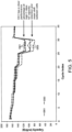
- the inventive membrane in at least one embodiment shows high rate discharge performance (see Figure 3 ) that is comparable to or better than Comparative Example 1 and Comparative Example 2.
- the inventive membrane in at least one embodiment demonstrates high capacity at both 5C and 10C, with 10C showing a significant, unexpected, and surprising improvement when compared to Comparative Examples 1 and 2.
- the instant single ply separator is characterized as follows: a microporous polypropylene film, made by a dry-stretch process; and having a 3D pore sphericity factor or ratio (MD/TD/ND), of from 1.0 to 2.0, an MD/TD pore aspect ratio of 1.0, an average pore size in the range of 0.090 to 0.99 microns ( ⁇ m) such as 0.090 to 0.099 microns ( ⁇ m); a thickness from 10 microns to 25 microns, a porosity in the range of 50-80%; a transverse direction tensile strength in a range of 500 kg/cm 2 -700 kg/cm 2 , and a machine direction (MD) tensile strength in a range of 700 kg/cm 2 -1000 kg/cm 2 .
- MD/TD/ND 3D pore sphericity factor or ratio
- the instant membrane may be one ply of the multi-ply membrane or the instant membrane may be all of the plies of the multi-ply membrane. If the instant membrane is less than all of the plies of the multi-ply membrane, the multi-ply membrane may be made via a lamination process. If the instant membrane is all plies of the multi-ply membrane, the multi-ply membrane additionally may be made via a co-extrusion process. Further, multi-ply membranes may be made of plies of the same materials or of differing materials.
- the instant membrane is preferably made by a dry-stretch process where the precursor membrane is biaxially stretched (i.e., not only stretched in the machine direction, but also in the transverse machine direction).
- the process for making the foregoing membrane includes the steps of extruding one or more polymers to form a nonporous precursor, and then biaxially stretching the nonporous precursor.
- the nonporous precursor may be annealed prior to stretching.
- the biaxial stretching includes a machine direction stretch and a transverse direction with a simultaneous controlled machine direction relax.
- the machine direction stretch and the transverse direction stretch may be simultaneous or sequential.
- the machine direction stretch is followed by the transverse direction stretch with the simultaneous machine direction relax. This process is discussed in greater detail below.
- Extrusion is generally according to a dry-stretch process.
- the extruder may have a slot die (for a flat precursor) or an annular die (for a parison precursor).
- an inflated parison technique may be employed (e.g., a blow up technique with a specific blow up ratio (BUR)).
- BUR blow up ratio
- the birefringence of the nonporous precursor does not have to be as high as in the conventional dry-stretch process.
- the birefringence of the precursor would be >0.0130; while with the instant process, the birefringence of the PP precursor could be as low as 0.0100.
- the birefringence of the precursor would be >0.0280; while with the instant process, the birefringence of the PE precursor could be as low as 0.0240.
- Annealing may be carried out, in one embodiment, at temperatures between T m -80° C. and T m -10° C. (where T m is the melt temperature of the polymer); and in another embodiment, at temperatures between T m -50° C. and T m -15° C.
- T m is the melt temperature of the polymer
- Machine direction stretch may be conducted as a cold stretch or a hot stretch or both, and as a single step or multiple steps.
- cold stretching may be carried out at ⁇ T m -50° C., and in another embodiment, at ⁇ T m -80° C.
- hot stretching may be carried out at ⁇ T m -10° C.
- total machine direction stretching may be in the range of 50-500%, and in another embodiment, in the range of 100-300%.
- the precursor may shrink in the transverse direction (conventional).
- Transverse direction stretching includes a simultaneous controlled machine direction relax. This means that as the precursor is stretched in the transverse direction, the precursor is simultaneously allowed to contract (i.e., relax), in a controlled manner, in the machine direction.
- the transverse direction stretching may be conducted as a cold step, or a hot step, or a combination of both. In one embodiment, total transverse direction stretching may be in the range of 100-1200%, and in another embodiment, in the range of 200-900%.
- the controlled machine direction relax may range from 5-80%, and in another embodiment, in the range of 15-65%.
- transverse stretching may be carried out in multiple steps. During transverse direction stretching, the precursor may or may not be allowed to shrink in the machine direction.
- the first transverse direction step may include a transverse stretch with the controlled machine relax, followed by simultaneous transverse and machine direction stretching, and followed by transverse direction relax and no machine direction stretch or relax.
- the precursor, after machine direction and transverse direction stretching may be subjected to a heat setting, as is well known.
- Polypropylene (PP) resin is extruded using a 2.5 inch extruder.
- the extruder melt temperature is about 221° C.
- Polymer melt is fed to a circular die.
- the die temperature is set at about 220° C., and the polymer melt is cooled by blowing air.
- Extruded precursor has a thickness in a range of about 1-1.5 mils, in some cases, 1.2-1.4 mils, and in some cases about 27 ⁇ m.
- the extruded film was then annealed at about 150° C. for about 2 minutes.
- the annealed film is then cold stretched to about 20% at room temperature, and then hot stretched to about 228% and relaxed to about 32% at a temperature in the range of 150-160° C.
- the MD stretched film is then transverse direction (TD) stretched 450% at a TD stretch temperature in the range of about 140-152 degrees C with a MD relax of 50%.
- the finished film has a thickness of 15 microns, and porosity of 74%.
- TD tensile strength of finished film is 529 Kg/cm 2 .
- Polypropylene (PP) resin is extruded using a 2.5 inch extruder.
- the extruder melt temperature is about 221° C.
- Polymer melt is fed to a circular die.
- the die temperature is set at about 220° C., and the polymer melt is cooled by blowing air.
- Extruded precursor has a thickness in a range of about 1-1.5 mils, in some cases, 1.2-1.4 mils, and in some cases about 27 ⁇ m.
- the extruded film was then annealed at about 150° C. for about 2 minutes.
- the annealed film is then cold stretched to about 20% at room temperature, and then hot stretched to about 228% and relaxed to about 32% at a temperature in the range of 160-170° C.
- the MD stretched film is then transverse direction (TD) stretched 450% at a TD stretch temperature in the range of about 150-160 degrees C with a MD relax of 50%.
- the finished film has a thickness of 20 microns, and porosity of 69%.
- TD tensile strength of finished film is 650 Kg/cm 2 .
- Thickness is measured using the Emveco Microgage 210-A precision micrometer thickness tester according to test procedure ASTM D374. Thickness values are reported in units of micrometers, ⁇ m.
- Test samples are first pre-conditioned to 73.4 deg C and a relative humidity of 50% for a minimum of 20 minutes.
- An Instron Model 4442 is used to measure puncture strength of test sample. Thirty measurements are made across the diagonal direction of a 1 1 ⁇ 4" ⁇ 40" continuous sample specimen and averaged. The needle has a 0.5 mm radius. The rate of descent is 25 mm/min. The film is held tight in a clamping device which utilizes an O-ring to securely hold the test sample in place. The diameter of this secured area is 25 mm. The displacement (in mm) of the film that was pierced by the needle is recorded against the resistance force (in gram force) developed by the tested film. The maximum resistance force is the puncture strength in units of gram force (gf). A load-versus-displacement plot is produced by this test method.
- Pore size is measured using the Aquapore available through Porous Materials, Inc. (PMI). Pore size is expressed in ⁇ m.
- the porosity of a microporous film sample is measured using ASTM method D-2873 and is defined as the percent void spaces in a microporous membrane..
- the tensile strength along the MD and TD is measured using Instron Model 4201 according to ASTM D-882 method.
- Shrinkage testing is measured by placing a 10 cm x 10 cm membrane sample in a manila folder which is then suspended in an oven using a clip. Shrinkage was measured using calipers in the MD and TD direction before and after a test sample were was placed in the oven at 105°C for 1 hour. Shrinkage was also measured using calipers in the MD and TD direction before and after a second test sample were was placed in the oven at 120°C for 1 hour. Shrinkage is expressed as a % MD shrinkage and % TD shrinkage using modified ASTM 2732-96.
- Hot Electrical Resistance is a measure of resistance of a separator film under 50 lb pressure while the temperature is linearly increased at a rate of 60 °C/minute.
- a 3/8" diameter piece of separator is saturated with electrolyte and sandwiched between two electrode discs made of Al or Cu.
- the rise in resistance is measured as Impedance and corresponds to a collapse in pore structure due to melting or "shutdown" of the microporous separator membrane.
- a microporous separator membrane has sustained high level of electrical resistance at elevated temperatures, this is indicative that the separator membrane may prevent electrode shorting in a battery.
- Cycles 1-5 have charge rate and discharge rate of C/10.
- Cycles 6-10 have a charge rate and discharge rate of C/5.
- Cycles 11-15 have a charge rate of C/5 and a discharge rate of C/2.
- Cycles 16-20 have a charge rate of C/5 and a discharge rate of 1C (charge/discharge rate capacity; 1C is a rate of full charge or discharge in 60 minutes).
- Cycles 21-25 have a charge rate of C/5 and a discharge rate of 5C.
- Cycles 26-30 have a charge rate of C/5 and a discharge rate of 10C.
- Cycles 31-35 have a charge rate and discharge rate of C/10.
- quick charge and/or discharge primary or secondary batteries including drone batteries, race car batteries, bus batteries, electric car batteries, hybrid vehicle batteries, and/or the like. Certain batteries are one time use primary quick charge and/or discharge lithium batteries. Other batteries are multi-use secondary quick charge and/or discharge lithium batteries. Preferred batteries may include quick charge lithium batteries, quick discharge lithium batteries, and/or quick charge and quick discharge lithium batteries.
- novel or improved battery separators base films or membranes, batteries, systems, vehicles, and/or methods of making and/or using such separators, films or membranes, batteries, systems, and/or methods of enhancing battery or cell charge rates, charge capacity, and/or discharge rates, and/or methods of improving batteries, systems including such batteries, vehicles including such batteries and/or systems, and/or the like; biaxially oriented porous membranes, composites including biaxially oriented porous membranes, biaxially oriented microporous membranes, biaxially oriented macroporous membranes, battery separators with improved charge capacities and the related methods and methods of manufacture, methods of use, and the like; filtration media, humidity control media, flat sheet membranes, liquid retention media; dry process separators; biaxially stretched separators; dry process biaxially stretched separators having a thickness range between about 5 ⁇ m and 50 ⁇ m, preferably between about 10 ⁇ m and 25 ⁇ m, having improved strength, high porosity, and unexpectedly
- novel or improved battery separators base films or membranes, batteries, cells, devices, systems, vehicles, and/or methods of making and/or using such separators, films or membranes, batteries, cells, devices, systems, vehicles, and/or the like.
- biaxially oriented porous membranes composites including biaxially oriented porous membranes, biaxially oriented microporous membranes, biaxially oriented macroporous membranes, battery separators, flat sheet membranes, or liquid retention media with improved charge capacities and disclosed herein are the related methods and methods of manufacture, methods of use, and/or the like.
- the possibly preferred inventive dry process separator may be biaxially stretched and has a thickness range between 10 ⁇ m and 25 ⁇ m having improved strength, high porosity, and unexpectedly and/or surprisingly high charge capacity, such as, for example, high 10C rate charge capacity.
- the preferred inventive separator's or membrane's high charge capacity and high porosity provide excellent charge rate and/or charge capacity performance in a rechargeable and/or secondary lithium battery, such as a lithium ion battery, for high power and/or high energy applications such as, by way of example only, Electric Drive Vehicles or Hybrid Electric Vehicles.
- the present invention is directed to improved microporous battery separators for secondary lithium batteries, improved microporous battery separators with enhanced or high charge rates and/or enhanced or high charge capacities in or for secondary lithium batteries, and/or related methods of manufacture, use, and/or the like.
- novel or improved battery separators base films or membranes, batteries, systems, vehicles, and/or methods of making and/or using such separators, films or membranes, batteries, systems, and/or methods of enhancing battery or cell charge rates, charge capacity, and/or discharge rates, and/or methods of improving batteries, systems including such batteries, vehicles including such batteries and/or systems, and/or the like; biaxially oriented porous membranes, composites including biaxially oriented porous membranes, biaxially oriented microporous membranes, biaxially oriented macroporous membranes, battery separators with improved charge capacities and the related methods and methods of manufacture, methods of use, and the like; filtration media, humidity control media, flat sheet membranes, liquid retention media; dry process separators; biaxially stretched separators; dry process biaxially stretched separators having a thickness range between about 5 ⁇ m and 50 ⁇ m, preferably between about 10 ⁇ m and 25 ⁇ m, having improved strength, high porosity, and unexpectedly
- inventive separators of at least certain embodiments of the present invention may be especially well suited or adapted for use in regenerative braking system batteries or cells in a regenerative braking system or equipped vehicle such as an electric, hybrid or electrified vehicle.
- Regenerative braking slows a vehicle by converting kinetic energy into electrical energy that can be stored in a battery or cell.
- the electric drive of the vehicle, or charging of the batteries or cells regenerative braking can extend the life of the braking system as its parts do not heat and wear as quickly.
- inventive separators of the present invention may likewise be especially well suited or adapted for use in high power and/or high energy battery applications such as, and by way of example only, Idle Start Stop Vehicles, Electric Drive Vehicles, Hybrid Electric Vehicles, power tools, cordless tools, Energy Storage Systems, UPS, backup power systems, combination lead acid battery and lithium battery systems, combination lithium battery and capacitor systems, and/or the like.
- the pores (openings) may have the following pore aspect ratios (based on physical dimensions of the pore opening in the machine direction (MD)(length), and transverse machine direction (TD)(width) by measuring, for example, one or more of the pores (preferably several of the pores to ascertain an average) in SEMs of the surface, top or front (A side) of selected membranes or composites, for example, mono-layer, bi-layer or tri-layer membranes:
- a three-dimensional or 3D pore sphericity factor or ratio (MD/TD/ND) range is 1.0 to 2.0 (based on physical dimensions of the pore openings in the machine direction (MD)(length), transverse machine direction (TD)(width) and thickness direction or cross section (ND)(thickness); for example, measuring the MD and TD of one or more pores (preferably several pores to ascertain an average) in SEMs of the surface, top or front (A side), or the surface, bottom or back (B side), and measuring the ND of one or more pores (preferably several pores to ascertain an average) in SEMs of the cross-section, depth, or height (C side)(either length or width cross-section or both)(the ND dimension may be of a different pore than the MD and TD dimension as it may be difficult to measure the ND, MD and TD dimension of the same pore
- the pores (openings) may have the following pore aspect ratios (based on physical dimensions of the pore opening in the machine direction (MD)(length), and transverse machine direction (TD)(width) based on measuring the pores in SEMs of the top or front (A side) of selected mono-layer and tri-layer membranes: Typical numbers for aspect ratio range of Machine direction MD (length) and Transverse direction TD (width): MD/TD aspect ratio in range of 0.75 to 1.50
- the pores (openings) may have the following three dimensional or 3D pore sphericity factors or ratios (based on physical dimensions of the pore openings in the machine direction (MD)(length), transverse machine direction (TD)(width) and thickness direction or cross section (ND)(thickness); for example, measuring one or more pores (preferably several pores to ascertain an average) in SEMs of the surface, top or front (A side), the surface, bottom or back (B side), and the cross-section, depth, or height (C side)(either length or width cross-section or both)(the ND dimension may be of a different pore than the MD and TD dimension as it may be difficult to measure the ND, MD and TD dimension of the same pore) of selected membranes, layers or composites, for example, of selected mono-layer and tri-layer membranes:
- the pores (openings) may have the following pore sphericity factors or ratios (based on physical dimensions of the pore opening in the machine direction (MD)(length), transverse machine direction (TD)(width) and thickness direction or cross section (ND)(thickness) based on measuring the pores in SEMs of the top or front (A side) and the length and with cross-sections (C side) of selected mono-layer and tri-layer membranes:
- a microporous membrane is made by a dry-stretch process and has substantially round shaped pores and a ratio of machine direction tensile strength to transverse direction tensile strength in the range of 0.5 to 6.0, preferably 0.5 to 5.0.
- the method of making the foregoing microporous membrane includes the steps of: extruding a polymer into a nonporous precursor, and biaxially stretching the nonporous precursor, the biaxial stretching including a machine direction stretching and a transverse direction stretching, the transverse direction stretching including a simultaneous controlled machine direction relax.
- a porous membrane is made by a modified dry-stretch process and has substantially round shaped pores, a ratio of machine direction tensile strength to transverse direction tensile strength in the range of 0.5 to 6.0, and has low Gurley and/or low ER as compared to prior dry-stretch membranes, has larger and more uniform mean flow pore diameters as compared to prior dry-stretch membranes, or both low Gurley and larger and more uniform mean flow pore diameters.
- the pores (openings) may have the following pore aspect ratios (based on physical dimensions of the pore opening in the machine direction (MD)(length), and transverse machine direction (TD)(width) by measuring, for example, one or more of the pores (preferably several of the pores to ascertain an average) in SEMs of the surface, top or front (A side) of selected membranes or composites, for example, mono-layer, bi-layer or tri-layer membranes:
- a three-dimensional or 3D pore sphericity factor or ratio (MD/TD/ND) range is 1.0 to 2.0 (based on physical dimensions of the pore openings in the machine direction (MD)(length), transverse machine direction (TD)(width) and thickness direction or cross section (ND)(thickness); for example, measuring the MD and TD of one or more pores (preferably several pores to ascertain an average) in SEMs of the surface, top or front (A side), or the surface, bottom or back (B side), and measuring the ND of one or more pores (preferably several pores to ascertain an average) in SEMs of the cross-section, depth, or height (C side)(either length or width cross-section or both)(the ND dimension may be of a different pore than the MD and TD dimension as it may be difficult to measure the ND, MD and TD dimension of the same pore
- the three-dimensional or 3D MD/TD/ND pore sphericity factor or ratio range is 1.0 to 2.0.
- the pores (openings) may have the following pore aspect ratios (based on physical dimensions of the pore opening in the machine direction (MD)(length), and transverse machine direction (TD)(width) based on measuring the pores in SEMs of the top or front (A side) of selected mono-layer and tri-layer membranes:
- MD machine direction
- TD transverse machine direction
- MD/TD aspect ratio in range of 0.75 to 1.50.
- the pores (openings) may have the following three dimensional or 3D pore sphericity factors or ratios (based on physical dimensions of the pore openings in the machine direction (MD)(length), transverse machine direction (TD)(width) and thickness direction or cross section (ND)(thickness); for example, measuring one or more pores (preferably several pores to ascertain an average) in SEMs of the surface, top or front (A side), the surface, bottom or back (B side), and the cross-section, depth, or height (C side)(either length or width cross-section or both)(the ND dimension may be of a different pore than the MD and TD dimension as it may be difficult to measure the ND, MD and TD dimension of the same pore) of selected membranes, layers or composites, for example, of selected mono-layer and tri-layer membranes:
- the pores (openings) may have the following pore sphericity factors or ratios (based on physical dimensions of the pore opening in the machine direction (MD)(length), transverse machine direction (TD)(width) and thickness direction or cross section (ND)(thickness) based on measuring the pores in SEMs of the top or front (A side) and the length and with cross-sections (C side) of selected mono-layer and tri-layer membranes:
- a microporous membrane is made by a dry-stretch process and has substantially round shaped pores and a ratio of machine direction tensile strength to transverse direction tensile strength in the range of 0.5 to 6.0, preferably 0.5 to 5.0.
- the method of making the foregoing microporous membrane includes the steps of: extruding a polymer into a nonporous precursor, and biaxially stretching the nonporous precursor, the biaxial stretching including a machine direction stretching and a transverse direction stretching, the transverse direction stretching including a simultaneous controlled machine direction relax.
- the present invention may address the above needs, and/or may be directed to novel or improved battery separators.
- base films or membranes, or batteries are also disclosed.
- the present invention or application is directed to biaxially oriented porous membranes, composites including biaxially oriented porous membranes, biaxially oriented microporous membranes, biaxially oriented macroporous membranes, battery separators, flat sheet membranes, and/or liquid retention media with improved charge capacities.
- the possibly preferred inventive dry process separator may be biaxially stretched.
- the membrane has a thickness range between 10 ⁇ m and 25 ⁇ m having improved strength, high porosity, and unexpectedly and/or surprisingly high charge capacity, such as, for example, high 10C rate charge capacity.
- the possibly preferred inventive separator's or membrane's high charge capacity and high porosity may provide excellent charge rate and/or charge capacity performance in a rechargeable and/or secondary lithium battery, such as a lithium ion battery, for high power and/or high energy applications such as, by way of example only, Electric Drive Vehicles or Hybrid Electric Vehicles.
- the present invention is directed to improved microporous battery separators for secondary lithium batteries, improved microporous battery separators with enhanced or high charge rates and/or enhanced or high charge capacities in or for secondary lithium batteries,. Also disclosed are related methods of manufacture, use, and/or the like.
- the present invention is directed to improved microporous battery separators for primary or secondary lithium batteries, high charge and/or discharge rate batteries, high charge and/or discharge rate batteries for drones, race cars, rapid charge busses, electric vehicles, hybrid electric vehicles, and/or other vehicles or devices requiring high charge and/or discharge rate batteries, high charge and/or discharge rate primary or secondary lithium batteries, high charge and/or discharge rate primary lithium batteries and/or high charge and/or discharge rate secondary lithium batteries, and/or methods related thereto and/or combinations thereof.
- novel or improved separators Disclosed herein are novel or improved separators, battery separators, lithium battery separators, batteries, cells, and/or methods of manufacture and/or use of such separators, battery separators, lithium battery separators, cells, and/or batteries; novel or improved battery separators for lithium ion primary or secondary batteries; novel or improved batteries or cells; novel or improved vehicles or devices; methods, systems and battery separators for enhancing battery charge rate, discharge rate, cycle life, and/or the like; and/or combinations thereof.
- novel or improved battery separators there are provided, novel or improved battery separators. Also disclosed are base films or membranes, batteries, cells, devices, systems, vehicles, and/or methods of making and/or using such separators, films or membranes, batteries, cells, devices, systems, vehicles, and/or methods of enhancing battery or cell charge rates, charge capacity, and/or discharge rates, and/or methods of improving batteries, systems including such batteries, vehicles including such batteries and/or systems, and/or the like; biaxially oriented porous membranes, composites including biaxially oriented porous membranes, biaxially oriented microporous membranes, biaxially oriented macroporous membranes, battery separators with improved charge capacities and the related methods and methods of manufacture, methods of use, and the like; flat sheet membranes, liquid retention media; dry process separators; biaxially stretched separators; dry process biaxially stretched separators preferably having a thickness range between about 5 ⁇ m and 50 ⁇ m, improved strength, high porosity, and unexpectedly and/
- membranes, separators and batteries of the appended claims are not limited in scope by the specific compositions and methods described herein, which are intended as illustrations of a few aspects of the claims.
- the singular forms "a,” “an,” and “the” include plural referents unless the context clearly dictates otherwise. Ranges may be expressed herein as from “about” one particular value, and/or to "about” another particular value. When such a range is expressed, another embodiment includes from the one particular value and/or to the other particular value. Similarly, when values are expressed as approximations, by use of the antecedent "about,” it will be understood that the particular value forms another embodiment.
- the word “comprise” and variations of the word, such as “comprising” and “comprises,” means “including but not limited to,” and is not intended to exclude, for example, other additives, components, integers, or steps.
- the terms “consisting essentially of” and “consisting of” can be used in place of “comprising” and “including” to provide for more specific embodiments of the invention and are also disclosed.
- “Exemplary” means “an example of” and is not intended to convey an indication of a preferred or ideal embodiment. "Such as” is not used in a restrictive sense, but for explanatory or exemplary purposes.
Landscapes
- Chemical & Material Sciences (AREA)
- Chemical Kinetics & Catalysis (AREA)
- Electrochemistry (AREA)
- General Chemical & Material Sciences (AREA)
- Engineering & Computer Science (AREA)
- Mechanical Engineering (AREA)
- Manufacturing & Machinery (AREA)
- Cell Separators (AREA)
- Manufacture Of Porous Articles, And Recovery And Treatment Of Waste Products (AREA)
- Materials Engineering (AREA)
- Extrusion Moulding Of Plastics Or The Like (AREA)
Description
- In accordance with at least selected embodiments, the present invention is directed to novel or improved battery separators. Also disclosed are base films or membranes, batteries, cells, devices, systems, and/or vehicles. Also disclosed are methods of making and/or using such separators, films or membranes, batteries, cells, devices, systems, and/or vehicles, and/or the like. In accordance with at least certain aspects, the present disclosure discloses biaxially oriented porous membranes, composites including biaxially oriented porous membranes, biaxially oriented microporous membranes, biaxially oriented macroporous membranes, battery separators, flat sheet membranes, and/or liquid retention media with improved charge capacities, and/or related methods, and/or methods of manufacture, methods of use, and/or the like. In accordance with at least certain selected embodiments, the possibly preferred inventive dry process separator may be biaxially stretched. The single ply separator has a thickness range between 10 µm and 25 µm having improved strength, high porosity, and unexpectedly and/or surprisingly high charge capacity, such as, for example, high 10C rate charge capacity. In addition, the possibly preferred inventive separator's or membrane's high charge capacity and high porosity may provide excellent charge rate and/or charge capacity performance in a rechargeable and/or secondary lithium battery, such as a lithium ion battery, for high power and/or high energy applications such as, by way of example only, Electric Drive Vehicles or Hybrid Electric Vehicles. In accordance with at least certain particular embodiments, the present invention is directed to improved microporous battery separators for secondary lithium batteries, improved microporous battery separators with enhanced or high charge rates and/or enhanced or high charge capacities in or for secondary lithium batteries. Also disclosed are related methods of manufacture, use, and/or the like.
- Porous polymer membranes can be made by various processes. Several processes are known and may have a significant impact on the characteristics that the resulting membrane will possess. See for example, Kesting, Robert E., Synthetic Polymeric Membranes, A structural perspective, Second Edition, John Wiley and Sons, New York, Y, (1985). Three well known processes for making porous polymer membranes include dry-stretch (also called dry process and/or the CELGARD® process), the wet process, and the particle stretch process.
- The dry process comprises at least three steps: extrusion, annealing, and stretching. Pores are formed during the stretching of the extruded polymer precursor. This stretching may be unidirectional, or in the machine direction (MD). See, for example, Kesting, Ibid. pages 290-297. The wet process, also known as phase inversion, involves the mixing of the polymer resins with a processing oil or a plasticizer, and/or other additives, and the mixture is then extruded and the processing oil or plasticizer is removed. During the wet process the pores are formed when the processing oil is removed. See, for example Kesting, Ibid. pages 237-286. In the particle stretch process, polymeric raw material is mixed with a particulate, and the mixture is extruded. The pores are formed during the stretching when the interface between the polymer and the particulate fractures due to the stretching forces. See for example,
U.S. Patent Nos. 6,057,061 and6,080,507 . - Each of these processes is unique and distinct, each resulting in a membrane that is physically different and distinguishable from the others. Distinguishing characteristics may include the shape and size of the pores. For examples, those membranes derived from the dry process may have slit-shaped pores due to the machine direction stretching, while membranes derived from certain wet processes may have rounder pores, sometimes with a lace like appearance, due to the plasticizer. And finally particle stretch membranes may have pores that appear more oval-like. In each of these processes, the mechanical strength is characterized in terms of the tensile strength the machine direction (MD) and transverse direction (TD).
U.S. Patent No. 8,795,565 describes a stretching of a dry process membrane along both the MD and the TD axes. Membranes biaxially stretched may have improved mechanical strength, which may be indicative of the membrane's strength profile within the battery. Furthermore, it has been shown to be advantageous to seek membranes with a balanced MD strength to TD strength ratio. - Batteries used in high power and/or high energy applications, for example, those used in Electric Drive Vehicles (EDVs), may need separators that enable the battery to have a high charge rate and/or a high charge capacity for optimal high energy performance. While rechargeable lithium ion batteries have been shown to be commercially viable for at least certain such high power and/or high energy applications, improvements are constantly needed in energy storage, power, and life cycle capabilities, particularly within the realm of separators that enable batteries to have unexpectedly high charge rate and/or high charge capacity. Furthermore, there is constantly a need for improved microporous battery separators or membranes that will meet the high energy performance requirements of not only the Electric Drive Vehicle battery market and the Hybrid Vehicle battery market, but also of more complex consumer electronics systems.
US Patent Publication No. 2015/270520 discloses embossed microporous membranes, as well as articles (e.g., battery separators, materials, textiles, composites, and laminates) comprising the embossed microporous membranes.US2007/196638 A1 discloses a biaxially oriented microporous membrane having improved pore shape and increased transverse direction tensile strength. - In accordance with at least selected embodiments, and as set out in the claims the present invention may address the above needs, and is directed to novel or improved battery separators. Disclosed too are, base films or membranes or batteries. Also disclosed are cells, devices, systems, and/or vehicles, and/or methods of making and/or using such separators, films or membranes, batteries, cells, devices, systems, and/or vehicles, and/or the like. Also disclosed are biaxially oriented porous membranes, composites including biaxially oriented porous membranes, biaxially oriented microporous membranes, biaxially oriented macroporous membranes, battery separators, flat sheet membranes, and/or liquid retention media with improved charge capacities. Also disclosed herein are related methods, and/or methods of manufacture, methods of use, and/or the like. In accordance with at least certain selected embodiments, the possibly preferred inventive dry process separator may be biaxially stretched. The single ply separator has a thickness range between 10 µm and 25 µm having improved strength, high porosity, and unexpectedly and/or surprisingly high charge capacity, such as, for example, high 10C rate charge capacity. In addition, the possibly preferred inventive separator's high charge capacity and high porosity may provide excellent charge rate and/or charge capacity performance in a rechargeable and/or secondary lithium battery, such as a lithium ion battery, for high power and/or high energy applications such as, by way of example only, Electric Drive Vehicles or Hybrid Electric Vehicles. In accordance with at least certain particular embodiments, the present invention is directed to improved microporous battery separators for secondary lithium batteries, improved microporous battery separators with enhanced or high charge rates and/or enhanced or high charge capacities in or for secondary lithium batteries, and also disclosed herein are related methods of manufacture, use, and/or the like. In accordance with at least certain selected embodiments, the present invention is directed to improved microporous battery separators for primary or secondary lithium batteries, high charge and/or discharge rate batteries, high charge and/or discharge rate batteries for drones, race cars, rapid charge busses, electric vehicles, hybrid electric vehicles, and/or other vehicles or devices requiring high charge and/or discharge rate batteries, high charge and/or discharge rate primary or secondary lithium batteries, high charge and/or discharge rate primary lithium batteries and/or high charge and/or discharge rate secondary lithium batteries, and/or combinations thereof and disclosed are methods related thereto
- In accordance with at least certain embodiments, aspects or objects, the present invention or application may address the above needs and is directed to novel or improved battery separators. Also disclosed are base films or membranes, and methods of making and/or using such separators, films or membranes. Also disclosed herein are biaxially oriented porous membranes, composites including biaxially oriented porous membranes, biaxially oriented microporous membranes, biaxially oriented macroporous membranes, battery separators, flat sheet membranes, or liquid (or electrolyte) retention media with improved charge capacities. Also disclosed are related methods, and/or methods of manufacture, methods of use, and the like. The possibly preferred inventive dry process separator may be biaxially stretched and may have a membrane thickness range between 10 µm and 25 µm, having improved strength, high porosity, and unexpectedly or surprisingly high charge capacity, such as, for example, high 10C rate charge capacity. In addition the preferred inventive separator's or membrane's high charge rate and/or high charge capacity and high porosity may provide excellent charge rate performance in a rechargeable lithium battery for high power and/or high energy applications such as Electric Drive Vehicles or Hybrid Electric Vehicles. Also disclosed herein are various methods of enhancing the C rate in a lithium secondary battery, as well as various improved batteries, such as hybrid batteries, such as batteries for hybrid electric vehicles, comprising a separator that enables such battery to have an unexpectedly or surprisingly high Crate.
- In accordance with at least certain embodiments, aspects or objects, the present invention or application may address the above needs, and/or discloses novel or improved battery separators, base films or membranes, (and disclosed herein are methods of making and/or using such separators, films or membranes,) especially for batteries used in high power and/or high energy applications, for example, those used in Electric Drive Vehicles (EDVs), and/or that need separators that enable the battery to have a high charge rate and/or a high charge capacity for optimal high energy performance, and/or in energy storage, power, and life cycle capabilities, and/or for batteries having unexpectedly high charge rate and/or high charge capacity, and/or to novel or improved microporous battery separators or membranes, coated separators or membranes, composite separators or membranes, and/or the like that may meet the high energy performance requirements of not only the Electric Drive Vehicle battery market and the Hybrid Vehicle battery market, but also of more complex consumer electronics systems, drone batteries, race car batteries, quick charge systems, quick charge busses, and/or the like.
- A possibly preferred novel porous battery separator has been developed for use in a lithium ion rechargeable battery. The possibly preferred inventive separator membrane, separator, base film or membrane is preferably a dry process microporous polypropylene monolayer configuration. The inventive polypropylene separator is prepared by the dry process (e.g., the CELGARD® dry process), and the separator or membrane can be uncoated, coated, treated, laminated to one or more other layers or materials (such as a glass or PP nonwoven material or layer), and/or the like.
- The preferred inventive membrane with its combination of balanced MD/TD strength, high porosity and high C-rate and/or charge capacity when in use in a battery has improved cycle life performance and/or a higher level of safety in a lithium or lithium ion rechargeable battery for use in high power end use applications.
- The exemplary inventive separator, with a thickness range of 10 µm to 25 µm, has a high charge rate and/or a high charge capacity and excellent discharge performance when compared to known battery separator membranes. A separator should have significant mechanical strength to endure the rigors of cell assembly as well as the rigors of continuous charge and discharge cycles throughout the lifetime of a battery. The inventive separator possibly preferably has a puncture strength over 100 gf, possibly more preferably over 200 gf, and possibly most preferably over 300 gf. In one particular example, the inventive separator has a puncture strength the ranging from 335 gf at a thickness of about 14 µm up to 400 gf at a thickness of about 20 µm. The inventive dry process microporous battery separator membrane preferably has equal or better separator charge performance and/or discharge performance and/or charge acceptance properties, and/or cycle life performance in a lithium ion secondary battery as wet process battery separator microporous membranes.
- Disclosed herein are novel or improved battery separators, base films or membranes, batteries, systems, vehicles, and/or methods of making and/or using such separators, films or membranes, batteries, systems, and/or methods of enhancing battery or cell charge rates, charge capacity, and/or discharge rates, and/or methods of improving batteries, systems including such batteries, vehicles including such batteries and/or systems, and/or the like; biaxially oriented porous membranes, composites including biaxially oriented porous membranes, biaxially oriented microporous membranes, biaxially oriented macroporous membranes, battery separators with improved charge capacities and the related methods and methods of manufacture, methods of use, and the like; flat sheet membranes, liquid retention media; dry process separators; biaxially stretched separators; dry process biaxially stretched separators having a thickness range between 10 µm and 25 µm, having improved strength, high porosity, and unexpectedly and/or surprisingly high charge capacity, such as, for example, high 10C rate charge capacity; separators or membranes with high charge capacity and high porosity, excellent charge rate and/or charge capacity performance in a rechargeable and/or secondary lithium battery, such as a lithium ion battery, for high power and/or high energy applications, cells, devices, systems, and/or vehicles, and/or the like; single or multiple ply or layer separators, monolayer separators, trilayer separators, composite separators, laminated separators, co-extruded separators, coated separators, 1 C or higher separators, at least 1 C separators, batteries, cells, systems, devices, vehicles, and/or the like; improved microporous battery separators for secondary lithium batteries, improved microporous battery separators with enhanced or high charge (C) rates, discharge (C) rates, and/or enhanced or high charge capacities in or for secondary lithium batteries, and/or related methods of manufacture, use, and/or the like, and/or combinations thereof.
- Certain aspects may be generally related to
U.S. Patent 8,795,565 B2 issued August 5, 2014 and/or toU.S. published application 2011/0223486 A1 published September 15, 2011 . -
-
Figure 1 is an SEM (scanning electron micrograph) surface view of a separator according to the biaxial stretch type process of Example 1 (EX1) at a magnification of 20,000x. -
Figure 2 is an SEM surface view of a separator according to Comparative Example 1 (CE1) at a magnification of 20,000x. -
Figure 3 demonstrates better discharge performance of EX1 and EX2 when compared to CE1 and CE2. CE1 is a microporous, dry process, 25 um thick, monolayer polypropylene (PP) membrane that is MD stretched only (no TD stretch). CE2 is a microporous, dry process, 16 um thick, monolayer polypropylene (PP) membrane that is MD stretched only (no TD stretch). -
Figure 4 demonstrates better C-rate performance of EX1 and EX2 when compared to CE1 and CE2. -
Figure 5 demonstrates better C-rate performance of EX1 compared to CE3. CE3 is a microporous, dry process, 16 um thick, monolayer polypropylene (PP) membrane that is MD stretched only (no TD stretch). - An exemplary novel or improved microporous battery separator has been developed for use in a lithium battery, such as a lithium ion rechargeable battery. In selected embodiments, the possibly preferred inventive separator membrane is a dry process polypropylene monolayer porous battery separator. In certain particular embodiments, the separator is manufactured using a homopolymer polypropylene, in some instances, with a melt flow index of 0.7-0.8.
- The instant membrane is preferably made by the dry-stretch process (also known as the CELGARD® process). The dry-stretch process refers to a process where formation results from stretching a nonporous precursor. See, Kesting, R., Synthetic Polymeric Membranes, A structural perspective, Second Edition, John Wiley & Sons, New York, N.Y., (1985), pages 290-297. The dry-stretch process is distinguished from the wet process and particle stretch process, as discussed above.
- The instant membrane may be distinguished from prior biaxially stretched dry-stretched membranes as the inventive membrane exhibits significant improvements in several ways, including but not limited to: exhibiting excellent high c-rate discharge performance, high c-rate charge performance, and/or demonstrating higher capacities and/or longer cycle life at higher c-rates.
- Regarding the discharge performance, the inventive membrane in at least one embodiment shows high rate discharge performance (see
Figure 3 ) that is comparable to or better than Comparative Example 1 and Comparative Example 2. - Regarding having higher capacities at higher c-rates (see
Figure 4 ) the inventive membrane in at least one embodiment demonstrates high capacity at both 5C and 10C, with 10C showing a significant, unexpected, and surprising improvement when compared to Comparative Examples 1 and 2. - The instant single ply separator is characterized as follows: a microporous polypropylene film, made by a dry-stretch process; and having a 3D pore sphericity factor or ratio (MD/TD/ND), of from 1.0 to 2.0, an MD/TD pore aspect ratio of 1.0, an average pore size in the range of 0.090 to 0.99 microns (µm) such as 0.090 to 0.099 microns (µm); a thickness from 10 microns to 25 microns, a porosity in the range of 50-80%; a transverse direction tensile strength in a range of 500 kg/cm 2 -700 kg/cm 2 , and a machine direction (MD) tensile strength in a range of 700 kg/cm 2 -1000 kg/cm 2 .
- Also disclosed is a multi-ply membrane. Regarding the multi-ply membrane, the instant membrane may be one ply of the multi-ply membrane or the instant membrane may be all of the plies of the multi-ply membrane. If the instant membrane is less than all of the plies of the multi-ply membrane, the multi-ply membrane may be made via a lamination process. If the instant membrane is all plies of the multi-ply membrane, the multi-ply membrane additionally may be made via a co-extrusion process. Further, multi-ply membranes may be made of plies of the same materials or of differing materials.
- The instant membrane is preferably made by a dry-stretch process where the precursor membrane is biaxially stretched (i.e., not only stretched in the machine direction, but also in the transverse machine direction). This process will be discussed in greater detail below. In general, the process for making the foregoing membrane includes the steps of extruding one or more polymers to form a nonporous precursor, and then biaxially stretching the nonporous precursor. Optionally, the nonporous precursor may be annealed prior to stretching. In one embodiment, the biaxial stretching includes a machine direction stretch and a transverse direction with a simultaneous controlled machine direction relax. The machine direction stretch and the transverse direction stretch may be simultaneous or sequential. In one embodiment, the machine direction stretch is followed by the transverse direction stretch with the simultaneous machine direction relax. This process is discussed in greater detail below.
- Extrusion is generally according to a dry-stretch process. The extruder may have a slot die (for a flat precursor) or an annular die (for a parison precursor). In the case of the latter, an inflated parison technique may be employed (e.g., a blow up technique with a specific blow up ratio (BUR)). However, the birefringence of the nonporous precursor does not have to be as high as in the conventional dry-stretch process. For example, in the conventional dry-stretch process to produce a membrane with a >35% porosity from a polypropylene resin, the birefringence of the precursor would be >0.0130; while with the instant process, the birefringence of the PP precursor could be as low as 0.0100. In another example, to produce a membrane with a >35% porosity from a polyethylene resin using a more conventional dry-stretch process, the birefringence of the precursor would be >0.0280; while with the instant process, the birefringence of the PE precursor could be as low as 0.0240.
- Annealing (optional) may be carried out, in one embodiment, at temperatures between Tm-80° C. and Tm-10° C. (where Tm is the melt temperature of the polymer); and in another embodiment, at temperatures between Tm-50° C. and Tm-15° C. Some materials, e.g., those with high crystallinity after extrusion, such as polybutene, may require no annealing.
- Machine direction stretch may be conducted as a cold stretch or a hot stretch or both, and as a single step or multiple steps. In one embodiment, cold stretching may be carried out at <Tm-50° C., and in another embodiment, at <Tm-80° C. In one embodiment, hot stretching may be carried out at <Tm-10° C. In one embodiment, total machine direction stretching may be in the range of 50-500%, and in another embodiment, in the range of 100-300%. During machine direction stretch, the precursor may shrink in the transverse direction (conventional).
- Transverse direction stretching includes a simultaneous controlled machine direction relax. This means that as the precursor is stretched in the transverse direction, the precursor is simultaneously allowed to contract (i.e., relax), in a controlled manner, in the machine direction. The transverse direction stretching may be conducted as a cold step, or a hot step, or a combination of both. In one embodiment, total transverse direction stretching may be in the range of 100-1200%, and in another embodiment, in the range of 200-900%. In one embodiment, the controlled machine direction relax may range from 5-80%, and in another embodiment, in the range of 15-65%. In one embodiment, transverse stretching may be carried out in multiple steps. During transverse direction stretching, the precursor may or may not be allowed to shrink in the machine direction. In an embodiment of a multi-step transverse direction stretching, the first transverse direction step may include a transverse stretch with the controlled machine relax, followed by simultaneous transverse and machine direction stretching, and followed by transverse direction relax and no machine direction stretch or relax.
- Optionally, the precursor, after machine direction and transverse direction stretching may be subjected to a heat setting, as is well known.
- The foregoing membrane and process are further illustrated in the following non-limiting examples.
- Polypropylene (PP) resin is extruded using a 2.5 inch extruder. The extruder melt temperature is about 221° C. Polymer melt is fed to a circular die. The die temperature is set at about 220° C., and the polymer melt is cooled by blowing air. Extruded precursor has a thickness in a range of about 1-1.5 mils, in some cases, 1.2-1.4 mils, and in some cases about 27 µm. The extruded film was then annealed at about 150° C. for about 2 minutes. The annealed film is then cold stretched to about 20% at room temperature, and then hot stretched to about 228% and relaxed to about 32% at a temperature in the range of 150-160° C. The MD stretched film is then transverse direction (TD) stretched 450% at a TD stretch temperature in the range of about 140-152 degrees C with a MD relax of 50%. The finished film has a thickness of 15 microns, and porosity of 74%. TD tensile strength of finished film is 529 Kg/cm2.
- Polypropylene (PP) resin is extruded using a 2.5 inch extruder. The extruder melt temperature is about 221° C. Polymer melt is fed to a circular die. The die temperature is set at about 220° C., and the polymer melt is cooled by blowing air. Extruded precursor has a thickness in a range of about 1-1.5 mils, in some cases, 1.2-1.4 mils, and in some cases about 27 µm. The extruded film was then annealed at about 150° C. for about 2 minutes. The annealed film is then cold stretched to about 20% at room temperature, and then hot stretched to about 228% and relaxed to about 32% at a temperature in the range of 160-170° C. The MD stretched film is then transverse direction (TD) stretched 450% at a TD stretch temperature in the range of about 150-160 degrees C with a MD relax of 50%. The finished film has a thickness of 20 microns, and porosity of 69%. TD tensile strength of finished film is 650 Kg/cm2.
- Features of the membranes formed according to Examples 1 and 2 as well as features of membranes used as Comparative Example 1 are shown below in Table 1.
Table 1 Properties CE1 EX2 EX1 Thickness (µm) 25 20 15 Porosity, % 55% 69% 74% Gurley (JIS), seconds 200 65 28 TD Shrinkage @ 90C/1 hr 0 0.1 0.2 MD Shrinkage @ 90C/1 hr 3-5 4.5 4.6 Puncture Strength, grams 335 400 220 MD Tensile (kg/cm2) 1055 950 788 TD Tensile (kg/cm2) 135 650 529 ER (ohm-cm2) 1.35 0.7 0.5 DB, Volts 1800 1600 900 Aquapore Size (um) 0.060 0.090 0.096 Mean Flow Pore Size (um) 0.036 0.050 0.50 - The separators described above as Examples 1 and 2 and Comparative Examples 1 and 2 were then tested for charge capacity and C rate, and the results are shown in Table 2 below:
Table 2 C- Rate 1C 10C CE1 158.38 mAh/g 102.34 mAh/g CE2 156.85 mAh/g 90.80 mAh/g EX1 156.91 mAh/g 111.63 mAh/g EX2 156.79 mAh/g 108.64 mAh/g - Thickness is measured using the Emveco Microgage 210-A precision micrometer thickness tester according to test procedure ASTM D374. Thickness values are reported in units of micrometers, µm.
- Test samples are first pre-conditioned to 73.4 deg C and a relative humidity of 50% for a minimum of 20 minutes. An Instron Model 4442 is used to measure puncture strength of test sample. Thirty measurements are made across the diagonal direction of a 1 ¼" × 40" continuous sample specimen and averaged. The needle has a 0.5 mm radius. The rate of descent is 25 mm/min. The film is held tight in a clamping device which utilizes an O-ring to securely hold the test sample in place. The diameter of this secured area is 25 mm. The displacement (in mm) of the film that was pierced by the needle is recorded against the resistance force (in gram force) developed by the tested film. The maximum resistance force is the puncture strength in units of gram force (gf). A load-versus-displacement plot is produced by this test method.
- Pore size is measured using the Aquapore available through Porous Materials, Inc. (PMI). Pore size is expressed in µm.
- The porosity of a microporous film sample is measured using ASTM method D-2873 and is defined as the percent void spaces in a microporous membrane..
- The tensile strength along the MD and TD is measured using Instron Model 4201 according to ASTM D-882 method.
- Shrinkage testing is measured by placing a 10 cm x 10 cm membrane sample in a manila folder which is then suspended in an oven using a clip. Shrinkage was measured using calipers in the MD and TD direction before and after a test sample were was placed in the oven at 105°C for 1 hour. Shrinkage was also measured using calipers in the MD and TD direction before and after a second test sample were was placed in the oven at 120°C for 1 hour. Shrinkage is expressed as a % MD shrinkage and % TD shrinkage using modified ASTM 2732-96.
- Hot Electrical Resistance is a measure of resistance of a separator film under 50 lb pressure while the temperature is linearly increased at a rate of 60 °C/minute. A 3/8" diameter piece of separator is saturated with electrolyte and sandwiched between two electrode discs made of Al or Cu. The rise in resistance is measured as Impedance and corresponds to a collapse in pore structure due to melting or "shutdown" of the microporous separator membrane. When a microporous separator membrane has sustained high level of electrical resistance at elevated temperatures, this is indicative that the separator membrane may prevent electrode shorting in a battery.
- All cycling was done in constant current (CC) mode. Cathode used is 622 NMC. Anode used is graphite. Electrolyte used 1 M LiPF6 salt in 3:7 v:v EC:EMC solvent. Voltage window is 3.0 - 4.3 V. Cycles 1-5 have charge rate and discharge rate of C/10. Cycles 6-10 have a charge rate and discharge rate of C/5. Cycles 11-15 have a charge rate of C/5 and a discharge rate of C/2. Cycles 16-20 have a charge rate of C/5 and a discharge rate of 1C (charge/discharge rate capacity; 1C is a rate of full charge or discharge in 60 minutes). Cycles 21-25 have a charge rate of C/5 and a discharge rate of 5C. Cycles 26-30 have a charge rate of C/5 and a discharge rate of 10C. Cycles 31-35 have a charge rate and discharge rate of C/10.
- Other examples include quick charge and/or discharge, primary or secondary batteries including drone batteries, race car batteries, bus batteries, electric car batteries, hybrid vehicle batteries, and/or the like. Certain batteries are one time use primary quick charge and/or discharge lithium batteries. Other batteries are multi-use secondary quick charge and/or discharge lithium batteries. Preferred batteries may include quick charge lithium batteries, quick discharge lithium batteries, and/or quick charge and quick discharge lithium batteries.
- Disclosed herein are novel or improved battery separators, base films or membranes, batteries, systems, vehicles, and/or methods of making and/or using such separators, films or membranes, batteries, systems, and/or methods of enhancing battery or cell charge rates, charge capacity, and/or discharge rates, and/or methods of improving batteries, systems including such batteries, vehicles including such batteries and/or systems, and/or the like; biaxially oriented porous membranes, composites including biaxially oriented porous membranes, biaxially oriented microporous membranes, biaxially oriented macroporous membranes, battery separators with improved charge capacities and the related methods and methods of manufacture, methods of use, and the like; filtration media, humidity control media, flat sheet membranes, liquid retention media; dry process separators; biaxially stretched separators; dry process biaxially stretched separators having a thickness range between about 5 µm and 50 µm, preferably between about 10 µm and 25 µm, having improved strength, high porosity, and unexpectedly and/or surprisingly high charge capacity, such as, for example, high 10C rate charge capacity; separators or membranes with high charge capacity and high porosity, excellent charge rate and/or charge capacity performance in a rechargeable and/or secondary lithium battery, such as a lithium ion battery, for high power and/or high energy applications such as, by way of example only, Electric Drive Vehicles (EDVs) or Hybrid Electric Vehicles (HEVs), electrified or electric assist vehicles, regenerative braking systems, idle start / stop systems (ISS), start / stop systems, Electric Vehicles (EVs), battery electric vehicles (BEVs), Plug In Hybrid Electric Vehicles (PHEVs), high charge or C rate electric vehicle batteries, high charge or C rate and high discharge or D rate electric vehicle batteries, e-bike batteries, e-cycle batteries, hybrid or multiple wheel drive electric vehicle batteries, consumer electronics, mobile devices, smart phones, laptops, tablets, polymer batteries, power cells, portable tool batteries, cordless tool batteries, cordless tools, and/or the like; single or multiple ply or layer separators, monolayer separators, trilayer separators, composite separators, laminated separators, co-extruded separators, coated separators, 1 C or higher separators (battery or cell fully charge or discharge in 60 minutes or less), 2 C or higher separators (battery or cell fully charge or discharge in 30 minutes or less), 10 C or higher separators (battery or cell fully charge or discharge in 6 minutes or less), 20 C or higher separators (battery or cell fully charge or discharge in 3 minutes or less), at least 1 C separators, at least 2 C separators, at least 10 C separators, at least 20 C separators, over 20 C separators, batteries, systems, devices, vehicles, and/or the like; improved microporous battery separators for secondary lithium batteries, improved microporous battery separators with enhanced or high charge (C) rates, discharge (C) rates, and/or enhanced or high charge capacities in or for secondary lithium batteries, and/or related methods of manufacture, use, and/or the like, and/or combinations thereof.
- Disclosed herein are novel or improved battery separators, base films or membranes, batteries, cells, devices, systems, vehicles, and/or methods of making and/or using such separators, films or membranes, batteries, cells, devices, systems, vehicles, and/or the like. Also disclosed are biaxially oriented porous membranes, composites including biaxially oriented porous membranes, biaxially oriented microporous membranes, biaxially oriented macroporous membranes, battery separators, flat sheet membranes, or liquid retention media with improved charge capacities and disclosed herein are the related methods and methods of manufacture, methods of use, and/or the like. The possibly preferred inventive dry process separator may be biaxially stretched and has a thickness range between 10 µm and 25 µm having improved strength, high porosity, and unexpectedly and/or surprisingly high charge capacity, such as, for example, high 10C rate charge capacity. In addition the preferred inventive separator's or membrane's high charge capacity and high porosity provide excellent charge rate and/or charge capacity performance in a rechargeable and/or secondary lithium battery, such as a lithium ion battery, for high power and/or high energy applications such as, by way of example only, Electric Drive Vehicles or Hybrid Electric Vehicles. In accordance with at least certain selected embodiments, the present invention is directed to improved microporous battery separators for secondary lithium batteries, improved microporous battery separators with enhanced or high charge rates and/or enhanced or high charge capacities in or for secondary lithium batteries, and/or related methods of manufacture, use, and/or the like.
- Disclosed herein are novel or improved battery separators, base films or membranes, batteries, systems, vehicles, and/or methods of making and/or using such separators, films or membranes, batteries, systems, and/or methods of enhancing battery or cell charge rates, charge capacity, and/or discharge rates, and/or methods of improving batteries, systems including such batteries, vehicles including such batteries and/or systems, and/or the like; biaxially oriented porous membranes, composites including biaxially oriented porous membranes, biaxially oriented microporous membranes, biaxially oriented macroporous membranes, battery separators with improved charge capacities and the related methods and methods of manufacture, methods of use, and the like; filtration media, humidity control media, flat sheet membranes, liquid retention media; dry process separators; biaxially stretched separators; dry process biaxially stretched separators having a thickness range between about 5 µm and 50 µm, preferably between about 10 µm and 25 µm, having improved strength, high porosity, and unexpectedly and/or surprisingly high charge capacity, such as, for example, high 10C rate charge capacity; separators or membranes with high charge capacity and high porosity, excellent charge rate and/or charge capacity performance in a rechargeable and/or secondary lithium battery, such as a lithium ion battery, for high power and/or high energy applications, cells, devices, systems, and/or vehicles, and/or the like; single or multiple ply or layer separators, monolayer separators, trilayer separators, composite separators, laminated separators, co-extruded separators, coated separators, 1 C or higher separators (separator enables the battery or cell to fully charge or discharge in 60 minutes or less), at least 1 C separators, batteries, systems, devices, vehicles, and/or the like; improved microporous battery separators for secondary lithium batteries, improved microporous battery separators with enhanced or high charge (C) rates, discharge (C) rates, and/or enhanced or high charge capacities in or for secondary lithium batteries, and/or related methods of manufacture, use, and/or the like, and/or combinations thereof.
- The inventive separators of at least certain embodiments of the present invention may be especially well suited or adapted for use in regenerative braking system batteries or cells in a regenerative braking system or equipped vehicle such as an electric, hybrid or electrified vehicle. Regenerative braking slows a vehicle by converting kinetic energy into electrical energy that can be stored in a battery or cell. In addition to improving the overall efficiency of the vehicle, the electric drive of the vehicle, or charging of the batteries or cells, regenerative braking can extend the life of the braking system as its parts do not heat and wear as quickly. The inventive separators of the present invention may likewise be especially well suited or adapted for use in high power and/or high energy battery applications such as, and by way of example only, Idle Start Stop Vehicles, Electric Drive Vehicles, Hybrid Electric Vehicles, power tools, cordless tools, Energy Storage Systems, UPS, backup power systems, combination lead acid battery and lithium battery systems, combination lithium battery and capacitor systems, and/or the like.
- At least selected porous material or porous membrane disclosed herein, the pores (openings) may have the following pore aspect ratios (based on physical dimensions of the pore opening in the machine direction (MD)(length), and transverse machine direction (TD)(width) by measuring, for example, one or more of the pores (preferably several of the pores to ascertain an average) in SEMs of the surface, top or front (A side) of selected membranes or composites, for example, mono-layer, bi-layer or tri-layer membranes:
- ∘ Typical:
- ∘ MD/TD aspect ratio in range of 0.75 to 1.50
- ∘ Preferred:
- ∘ MD/TD aspect ratio in range of 0.75 to 1.25
- ∘ Most Preferred:
- ∘ MD/TD aspect ratio in range of 0.85 to 1.25
- In accordance with at least selected porous material or porous membrane embodiments of the present invention, if the MD/TD pore aspect ratio were 1.0, then a three-dimensional or 3D pore sphericity factor or ratio (MD/TD/ND) range is 1.0 to 2.0 (based on physical dimensions of the pore openings in the machine direction (MD)(length), transverse machine direction (TD)(width) and thickness direction or cross section (ND)(thickness); for example, measuring the MD and TD of one or more pores (preferably several pores to ascertain an average) in SEMs of the surface, top or front (A side), or the surface, bottom or back (B side), and measuring the ND of one or more pores (preferably several pores to ascertain an average) in SEMs of the cross-section, depth, or height (C side)(either length or width cross-section or both)(the ND dimension may be of a different pore than the MD and TD dimension as it may be difficult to measure the ND, MD and TD dimension of the same pore).
- In selected porous material or porous membrane embodiments disclosed herein, the pores (openings) may have the following pore aspect ratios (based on physical dimensions of the pore opening in the machine direction (MD)(length), and transverse machine direction (TD)(width) based on measuring the pores in SEMs of the top or front (A side) of selected mono-layer and tri-layer membranes: Typical numbers for aspect ratio range of Machine direction MD (length) and Transverse direction TD (width): MD/TD aspect ratio in range of 0.75 to 1.50
- In selected porous material or porous membrane embodiments disclosed herein, the pores (openings) may have the following three dimensional or 3D pore sphericity factors or ratios (based on physical dimensions of the pore openings in the machine direction (MD)(length), transverse machine direction (TD)(width) and thickness direction or cross section (ND)(thickness); for example, measuring one or more pores (preferably several pores to ascertain an average) in SEMs of the surface, top or front (A side), the surface, bottom or back (B side), and the cross-section, depth, or height (C side)(either length or width cross-section or both)(the ND dimension may be of a different pore than the MD and TD dimension as it may be difficult to measure the ND, MD and TD dimension of the same pore) of selected membranes, layers or composites, for example, of selected mono-layer and tri-layer membranes:
- ∘ For example:
- ∘ Typical:
- ∘ MD/TD aspect ratio in range of 0.75 to 1.50
- ∘ MD/ND dimension ratio in range of 0.50 to 7.50
- ∘ TD/ND dimension ratio in range of 0.50 to 5.00
- ∘ Preferred:
- ∘ MD/TD aspect ratio in range of 0.75 to 1.25
- ∘ MD/ND dimension ratio in range of 1.0 to 2.5
- ∘ TD/ND dimension ratio in range of 1.0 to 2.5
- ∘ Most Preferred:
- ∘ MD/TD aspect ratio in range of 0.85 to 1.25
- ∘ MD/ND dimension ratio in range of 1.0 to 2.0
- ∘ TD/ND dimension ratio in range of 1.0 to 2.0
- ∘ Typical:
- In selected porous material or porous membrane embodiments disclosed herein the pores (openings) may have the following pore sphericity factors or ratios (based on physical dimensions of the pore opening in the machine direction (MD)(length), transverse machine direction (TD)(width) and thickness direction or cross section (ND)(thickness) based on measuring the pores in SEMs of the top or front (A side) and the length and with cross-sections (C side) of selected mono-layer and tri-layer membranes:
- ∘ Typical numbers for sphericity factor or ratio range of Machine direction MD (length), Transverse direction TD (width), and
- ∘ Thickness direction ND (vertical height):
- ∘ MD/TD aspect ratio in range of 0.75 to 1.50
- ∘ MD/ND dimension ratio in range of 0.50 to 7.50
- ∘ TD/ND dimension ratio in range of 0.50 to 5.00
- In accordance with at least selected aspects of the present disclosure, a microporous membrane is made by a dry-stretch process and has substantially round shaped pores and a ratio of machine direction tensile strength to transverse direction tensile strength in the range of 0.5 to 6.0, preferably 0.5 to 5.0. The method of making the foregoing microporous membrane includes the steps of: extruding a polymer into a nonporous precursor, and biaxially stretching the nonporous precursor, the biaxial stretching including a machine direction stretching and a transverse direction stretching, the transverse direction stretching including a simultaneous controlled machine direction relax.
- In accordance with at least selected aspects of the present disclosure, a porous membrane is made by a modified dry-stretch process and has substantially round shaped pores, a ratio of machine direction tensile strength to transverse direction tensile strength in the range of 0.5 to 6.0, and has low Gurley and/or low ER as compared to prior dry-stretch membranes, has larger and more uniform mean flow pore diameters as compared to prior dry-stretch membranes, or both low Gurley and larger and more uniform mean flow pore diameters.
- In selected porous material or porous membrane embodiments disclosed herein, the pores (openings) may have the following pore aspect ratios (based on physical dimensions of the pore opening in the machine direction (MD)(length), and transverse machine direction (TD)(width) by measuring, for example, one or more of the pores (preferably several of the pores to ascertain an average) in SEMs of the surface, top or front (A side) of selected membranes or composites, for example, mono-layer, bi-layer or tri-layer membranes:
- ∘ Typical:
- ∘ MD/TD aspect ratio in range of 0.75 to 1.50
- ∘ Preferred:
- ∘ MD/TD aspect ratio in range of 0.75 to 1.25
- ∘ Most Preferred:
- ∘ MD/TD aspect ratio in range of 0.85 to 1.25
- In accordance with at least selected porous material or porous membrane embodiments of the present invention, if the MD/TD pore aspect ratio were 1.0, then a three-dimensional or 3D pore sphericity factor or ratio (MD/TD/ND) range is 1.0 to 2.0 (based on physical dimensions of the pore openings in the machine direction (MD)(length), transverse machine direction (TD)(width) and thickness direction or cross section (ND)(thickness); for example, measuring the MD and TD of one or more pores (preferably several pores to ascertain an average) in SEMs of the surface, top or front (A side), or the surface, bottom or back (B side), and measuring the ND of one or more pores (preferably several pores to ascertain an average) in SEMs of the cross-section, depth, or height (C side)(either length or width cross-section or both)(the ND dimension may be of a different pore than the MD and TD dimension as it may be difficult to measure the ND, MD and TD dimension of the same pore).
- In the porous material or porous membrane of the present invention, the three-dimensional or 3D MD/TD/ND pore sphericity factor or ratio range is 1.0 to 2.0.
- In selected porous material or porous membrane embodiments disclosed herein, the pores (openings) may have the following pore aspect ratios (based on physical dimensions of the pore opening in the machine direction (MD)(length), and transverse machine direction (TD)(width) based on measuring the pores in SEMs of the top or front (A side) of selected mono-layer and tri-layer membranes: Here are the typical numbers for aspect ratio range of Machine direction MD (length) and Transverse direction TD (width): MD/TD aspect ratio in range of 0.75 to 1.50.
- In selected porous material or porous membrane embodiments disclosed herein, the pores (openings) may have the following three dimensional or 3D pore sphericity factors or ratios (based on physical dimensions of the pore openings in the machine direction (MD)(length), transverse machine direction (TD)(width) and thickness direction or cross section (ND)(thickness); for example, measuring one or more pores (preferably several pores to ascertain an average) in SEMs of the surface, top or front (A side), the surface, bottom or back (B side), and the cross-section, depth, or height (C side)(either length or width cross-section or both)(the ND dimension may be of a different pore than the MD and TD dimension as it may be difficult to measure the ND, MD and TD dimension of the same pore) of selected membranes, layers or composites, for example, of selected mono-layer and tri-layer membranes:
- ∘ For example:
- ∘ Typical:
- ∘ MD/TD aspect ratio in range of 0.75 to 1.50
- ∘ MD/ND dimension ratio in range of 0.50 to 7.50
- ∘ TD/ND dimension ratio in range of 0.50 to 5.00
- ∘ Preferred:
- ∘ MD/TD aspect ratio in range of 0.75 to 1.25
- ∘ MD/ND dimension ratio in range of 1.0 to 2.5
- ∘ TD/ND dimension ratio in range of 1.0 to 2.5
- ∘ Most Preferred:
- ∘ MD/TD aspect ratio in range of 0.85 to 1.25
- ∘ MD/ND dimension ratio in range of 1.0 to 2.0
- ∘ TD/ND dimension ratio in range of 1.0 to 2.0
- ∘ Typical:
- In accordance with at least selected porous material or porous membrane aspects of the present disclosure, the pores (openings) may have the following pore sphericity factors or ratios (based on physical dimensions of the pore opening in the machine direction (MD)(length), transverse machine direction (TD)(width) and thickness direction or cross section (ND)(thickness) based on measuring the pores in SEMs of the top or front (A side) and the length and with cross-sections (C side) of selected mono-layer and tri-layer membranes:
- ∘ Here are the typical numbers for sphericity factor or ratio range of Machine direction MD (length), Transverse direction TD (width), and Thickness direction ND (vertical height):
- ∘ MD/TD aspect ratio in range of 0.75 to 1.50
- ∘ MD/ND dimension ratio in range of 0.50 to 7.50
- ∘ TD/ND dimension ratio in range of 0.50 to 5.00
- In accordance with at least selected aspects of the present disclosure, a microporous membrane is made by a dry-stretch process and has substantially round shaped pores and a ratio of machine direction tensile strength to transverse direction tensile strength in the range of 0.5 to 6.0, preferably 0.5 to 5.0. The method of making the foregoing microporous membrane includes the steps of: extruding a polymer into a nonporous precursor, and biaxially stretching the nonporous precursor, the biaxial stretching including a machine direction stretching and a transverse direction stretching, the transverse direction stretching including a simultaneous controlled machine direction relax.
- In accordance with at least selected embodiments, the present invention may address the above needs, and/or may be directed to novel or improved battery separators. Also disclosed herein are base films or membranes, or batteries. Also disclosed are cells, devices, systems, and/or vehicles, and/or methods of making and/or using such separators, films or membranes, batteries, cells, devices, systems, and/or vehicles, and/or the like. In accordance with at least certain embodiments the present invention or application is directed to biaxially oriented porous membranes, composites including biaxially oriented porous membranes, biaxially oriented microporous membranes, biaxially oriented macroporous membranes, battery separators, flat sheet membranes, and/or liquid retention media with improved charge capacities. Also disclosed are related methods, and/or methods of manufacture, methods of use, and/or the like. In accordance with at least certain selected embodiments, the possibly preferred inventive dry process separator may be biaxially stretched. The membrane has a thickness range between 10 µm and 25 µm having improved strength, high porosity, and unexpectedly and/or surprisingly high charge capacity, such as, for example, high 10C rate charge capacity. In addition, the possibly preferred inventive separator's or membrane's high charge capacity and high porosity may provide excellent charge rate and/or charge capacity performance in a rechargeable and/or secondary lithium battery, such as a lithium ion battery, for high power and/or high energy applications such as, by way of example only, Electric Drive Vehicles or Hybrid Electric Vehicles. In accordance with at least certain particular embodiments, the present invention is directed to improved microporous battery separators for secondary lithium batteries, improved microporous battery separators with enhanced or high charge rates and/or enhanced or high charge capacities in or for secondary lithium batteries,. Also disclosed are related methods of manufacture, use, and/or the like. In accordance with at least certain selected embodiments, the present invention is directed to improved microporous battery separators for primary or secondary lithium batteries, high charge and/or discharge rate batteries, high charge and/or discharge rate batteries for drones, race cars, rapid charge busses, electric vehicles, hybrid electric vehicles, and/or other vehicles or devices requiring high charge and/or discharge rate batteries, high charge and/or discharge rate primary or secondary lithium batteries, high charge and/or discharge rate primary lithium batteries and/or high charge and/or discharge rate secondary lithium batteries, and/or methods related thereto and/or combinations thereof.
- Disclosed herein are novel or improved separators, battery separators, lithium battery separators, batteries, cells, and/or methods of manufacture and/or use of such separators, battery separators, lithium battery separators, cells, and/or batteries; novel or improved battery separators for lithium ion primary or secondary batteries; novel or improved batteries or cells; novel or improved vehicles or devices; methods, systems and battery separators for enhancing battery charge rate, discharge rate, cycle life, and/or the like; and/or combinations thereof.
- There are provided, novel or improved battery separators. Also disclosed are base films or membranes, batteries, cells, devices, systems, vehicles, and/or methods of making and/or using such separators, films or membranes, batteries, cells, devices, systems, vehicles, and/or methods of enhancing battery or cell charge rates, charge capacity, and/or discharge rates, and/or methods of improving batteries, systems including such batteries, vehicles including such batteries and/or systems, and/or the like; biaxially oriented porous membranes, composites including biaxially oriented porous membranes, biaxially oriented microporous membranes, biaxially oriented macroporous membranes, battery separators with improved charge capacities and the related methods and methods of manufacture, methods of use, and the like; flat sheet membranes, liquid retention media; dry process separators; biaxially stretched separators; dry process biaxially stretched separators preferably having a thickness range between about 5 µm and 50 µm, improved strength, high porosity, and unexpectedly and/or surprisingly high charge capacity, such as, for example, high 10C rate charge capacity; separators or membranes with high charge capacity and high porosity, excellent charge rate and/or charge capacity performance in a rechargeable and/or secondary lithium battery, such as a lithium ion battery, for high power and/or high energy applications, cells, devices, systems, and/or vehicles, and/or the like; single or multiple ply or layer separators, monolayer separators, trilayer separators, composite separators, laminated separators, co-extruded separators, coated separators, 1 C or higher separators, at least 1 C separators, batteries, cells, systems, devices, vehicles, and/or the like; improved microporous battery separators for secondary lithium batteries, improved microporous battery separators with enhanced or high charge (C) rates, discharge (C) rates, and/or enhanced or high charge capacities in or for secondary lithium batteries, and/or related methods of manufacture, use, and/or the like, and/or combinations thereof are disclosed or provided.
- The present invention may be embodied in other forms without departing from the appended claims. Accordingly, reference should be made to the appended claims, rather than to the foregoing specification, as indicating the scope of the invention.
- The foregoing written description of structures and methods has been presented for purposes of illustration only. Examples are used to disclose exemplary embodiments, including the best mode, and also to enable any person skilled in the art to practice the invention, including making and using any devices or systems and performing any incorporated methods. These examples are not intended to be exhaustive or to limit the invention to the precise steps and/or forms disclosed, and many modifications and variations are possible in light of the above teaching and within the scope of the appended claims. Features described herein may be combined in any combination. Steps of a method described herein may be performed in any sequence that is physically possible. The patentable scope of the invention is defined by the appended claims, and may include other examples that occur to those skilled in the art. The membranes, separators and batteries of the appended claims are not limited in scope by the specific compositions and methods described herein, which are intended as illustrations of a few aspects of the claims. As used in the specification and the appended claims, the singular forms "a," "an," and "the" include plural referents unless the context clearly dictates otherwise. Ranges may be expressed herein as from "about" one particular value, and/or to "about" another particular value. When such a range is expressed, another embodiment includes from the one particular value and/or to the other particular value. Similarly, when values are expressed as approximations, by use of the antecedent "about," it will be understood that the particular value forms another embodiment. It will be further understood that the endpoints of each of the ranges are significant both in relation to the other endpoint, and independently of the other endpoint. "Optional" or "optionally" means that the subsequently described event or circumstance may or may not occur, and that the description includes instances where said event or circumstance occurs and instances where it does not.
- Throughout the description and claims of this specification, the word "comprise" and variations of the word, such as "comprising" and "comprises," means "including but not limited to," and is not intended to exclude, for example, other additives, components, integers, or steps. The terms "consisting essentially of" and "consisting of" can be used in place of "comprising" and "including" to provide for more specific embodiments of the invention and are also disclosed. "Exemplary" means "an example of" and is not intended to convey an indication of a preferred or ideal embodiment. "Such as" is not used in a restrictive sense, but for explanatory or exemplary purposes.
- Other than where noted, all numbers expressing geometries, dimensions, and so forth used in the specification and claims are to be understood at the very least, and not as an attempt to limit the application of the doctrine of equivalents to the scope of the claims, to be construed in light of the number of significant digits and ordinary rounding approaches.
- Unless defined otherwise, all technical and scientific terms used herein have the same meanings as commonly understood by one of skill in the art to which the disclosed invention belongs.
- Additionally, the invention illustratively disclosed herein and in accordance with the appended claims suitably may be practiced in the absence of any element which is not specifically disclosed herein.
Claims (4)
- A single ply separator comprising:a microporous polypropylene film, made by a dry-stretch process; andhaving a 3D pore sphericity factor or ratio (MD/TD/ND) of from 1.0 to 2.0, an MD/TD pore aspect ratio of 1.0, an average pore size from 0.09 to 0.99 microns, a thickness from 10 microns to 25 microns, a ratio of machine direction tensile strength to transverse direction tensile strength in a range of 1.4 to 1.6, a porosity in a range of 60% to 80%, a transverse direction (TD) tensile strength in a range of 500 kg/cm2-700 kg/cm2, and a machine direction (MD) tensile strength in a range of 700 kg/cm2-1000 kg/cm2.
- The single ply separator according to claim 1 wherein the polypropylene has a crystallinity in the range of 20-80%.
- The single ply separator according to claim 1 wherein said transverse tensile strength being ≧500 Kg/cm2.
- The single ply separator according to claim 1 having a machine direction (MD) tensile strength in the range of 750-950 Kg/cm2.
Priority Applications (1)
| Application Number | Priority Date | Filing Date | Title |
|---|---|---|---|
| EP23172388.3A EP4234206A3 (en) | 2016-01-29 | 2017-01-27 | Improved separators, batteries systems, vehicles, and related methods |
Applications Claiming Priority (2)
| Application Number | Priority Date | Filing Date | Title |
|---|---|---|---|
| US15/009,888 US20170222205A1 (en) | 2016-01-29 | 2016-01-29 | Separators, batteries, systems, vehicles, and related methods |
| PCT/US2017/015230 WO2017132439A1 (en) | 2016-01-29 | 2017-01-27 | Improved separators, battereies systems, vehicles, and related methods |
Related Child Applications (2)
| Application Number | Title | Priority Date | Filing Date |
|---|---|---|---|
| EP23172388.3A Division EP4234206A3 (en) | 2016-01-29 | 2017-01-27 | Improved separators, batteries systems, vehicles, and related methods |
| EP23172388.3A Division-Into EP4234206A3 (en) | 2016-01-29 | 2017-01-27 | Improved separators, batteries systems, vehicles, and related methods |
Publications (3)
| Publication Number | Publication Date |
|---|---|
| EP3411916A1 EP3411916A1 (en) | 2018-12-12 |
| EP3411916A4 EP3411916A4 (en) | 2019-09-11 |
| EP3411916B1 true EP3411916B1 (en) | 2023-10-11 |
Family
ID=59387101
Family Applications (2)
| Application Number | Title | Priority Date | Filing Date |
|---|---|---|---|
| EP23172388.3A Pending EP4234206A3 (en) | 2016-01-29 | 2017-01-27 | Improved separators, batteries systems, vehicles, and related methods |
| EP17744931.1A Active EP3411916B1 (en) | 2016-01-29 | 2017-01-27 | Improved separators, batteries systems, vehicles, and related methods |
Family Applications Before (1)
| Application Number | Title | Priority Date | Filing Date |
|---|---|---|---|
| EP23172388.3A Pending EP4234206A3 (en) | 2016-01-29 | 2017-01-27 | Improved separators, batteries systems, vehicles, and related methods |
Country Status (6)
| Country | Link |
|---|---|
| US (5) | US20170222205A1 (en) |
| EP (2) | EP4234206A3 (en) |
| JP (3) | JP2019505071A (en) |
| KR (1) | KR102897090B1 (en) |
| CN (2) | CN114709553A (en) |
| WO (1) | WO2017132439A1 (en) |
Families Citing this family (8)
| Publication number | Priority date | Publication date | Assignee | Title |
|---|---|---|---|---|
| KR102319967B1 (en) | 2019-01-10 | 2021-10-29 | 삼성에스디아이 주식회사 | Separator for rechargeable lithium battery, and method for preparing the same, and rechargeable lithium battery including the same |
| KR102431613B1 (en) * | 2019-02-26 | 2022-08-12 | 한국자동차연구원 | Seperator for fuel cell |
| JP7489767B2 (en) * | 2019-11-06 | 2024-05-24 | 住友化学株式会社 | Method for manufacturing separator for non-aqueous electrolyte secondary battery, method for manufacturing member for non-aqueous electrolyte secondary battery, and method for manufacturing non-aqueous electrolyte secondary battery |
| EP4115461A1 (en) * | 2020-03-07 | 2023-01-11 | Slobodan Petrovic | Inserted cavity electrode lithium battery |
| JP7682671B2 (en) * | 2021-03-30 | 2025-05-26 | 住友化学株式会社 | Separator for non-aqueous electrolyte secondary battery, component for non-aqueous electrolyte secondary battery, and non-aqueous electrolyte secondary battery |
| CN115810874B (en) * | 2022-07-11 | 2024-10-11 | 宁德时代新能源科技股份有限公司 | A separator, a method for preparing the same, and a secondary battery and an electric device containing the same |
| CN115274315B (en) * | 2022-09-27 | 2022-12-20 | 江苏中奕和创智能科技有限公司 | Capacitor for energy storage lithium battery system |
| TWI875331B (en) * | 2023-11-23 | 2025-03-01 | 富邦先進材料股份有限公司 | Preparation method of microporous film material |
Citations (1)
| Publication number | Priority date | Publication date | Assignee | Title |
|---|---|---|---|---|
| US20070196638A1 (en) * | 2006-02-21 | 2007-08-23 | Xiangyun Wei | Biaxially oriented microporous membrane |
Family Cites Families (27)
| Publication number | Priority date | Publication date | Assignee | Title |
|---|---|---|---|---|
| CA2104955C (en) * | 1991-12-27 | 1998-08-25 | Kazuo Yagi | Biaxially oriented film of high molecular weight polyethylene, process for preparing the same, surface-modified biaxially oriented film of high molecular weight polyethylene and process for preparing the same |
| GB9318751D0 (en) | 1993-09-09 | 1993-10-27 | Health Lab Service Board | Detection and speciation of campylobacter |
| JPH107832A (en) * | 1996-04-26 | 1998-01-13 | Mitsui Petrochem Ind Ltd | High strength polypropylene porous film and method for producing the same |
| US6057061A (en) | 1997-11-13 | 2000-05-02 | Celgard Inc. | Ethylene-vinyl alcohol copolymer battery separator |
| US6080507A (en) | 1998-04-13 | 2000-06-27 | Celgard Inc. | Trilayer battery separator |
| US6096213A (en) * | 1998-08-14 | 2000-08-01 | 3M Innovative Properties Company | Puncture-resistant polyolefin membranes |
| US6391069B1 (en) * | 2000-03-29 | 2002-05-21 | Valence Technology (Nevada), Inc. | Method of making bonded-electrode rechargeable electrochemical cells |
| US7875380B2 (en) * | 2003-06-17 | 2011-01-25 | Nanophil Co., Ltd. | Complex membrane for electrochemical device, manufacturing method and electrochemical device having the same |
| KR100775310B1 (en) * | 2004-12-22 | 2007-11-08 | 주식회사 엘지화학 | Organic/inorganic composite microporous membrane and electrochemical device prepared thereby |
| CN101384409A (en) * | 2006-02-21 | 2009-03-11 | 赛尔格有限责任公司 | biaxially oriented microporous membrane |
| US20070238017A1 (en) * | 2006-04-07 | 2007-10-11 | Celgard Llc | Multilayer separator exhibiting improved strength and stability |
| US20110059368A1 (en) * | 2008-05-09 | 2011-03-10 | Daisuke Inagaki | Separtor for high-power density lithium ion secondary battery (as amended) |
| KR100928898B1 (en) * | 2009-04-17 | 2009-11-30 | (주)씨에스텍 | Preparation method of microporous polymer membrane and microporous polymer membrane prepared by the above method |
| WO2011038314A1 (en) | 2009-09-28 | 2011-03-31 | E. I. Du Pont De Nemours And Company | Methods of making glass-crystalline particles including a glass component and a crystalline component |
| WO2011077542A1 (en) * | 2009-12-25 | 2011-06-30 | トヨタ自動車株式会社 | Nonaqueous electrolyte lithium ion secondary battery and vehicle |
| US9453805B2 (en) * | 2010-01-19 | 2016-09-27 | Celgard, Llc | X-ray sensitive battery separators and related methods |
| US20110223486A1 (en) * | 2010-03-12 | 2011-09-15 | Xiaomin Zhang | Biaxially oriented porous membranes, composites, and methods of manufacture and use |
| CN107316969B (en) | 2010-11-26 | 2020-04-21 | 丰田自动车株式会社 | Non-aqueous electrolyte secondary battery |
| EP3272500B1 (en) * | 2010-12-28 | 2019-06-26 | Asahi Kasei Kabushiki Kaisha | Polyolefin-based porous film |
| US9666848B2 (en) * | 2011-05-20 | 2017-05-30 | Dreamweaver International, Inc. | Single-layer lithium ion battery separator |
| WO2013054929A1 (en) * | 2011-10-14 | 2013-04-18 | 東レ株式会社 | Porous polypropylene film and electrical storage device |
| JP5723353B2 (en) * | 2012-12-03 | 2015-05-27 | 三菱樹脂株式会社 | Method for producing laminated porous film |
| JP2014141644A (en) * | 2012-12-26 | 2014-08-07 | Toray Ind Inc | Biaxially oriented porous polypropylene film, separator film for electricity storage device and electricity storage device |
| CN103147224B (en) * | 2013-02-22 | 2016-01-06 | 哈尔滨工业大学深圳研究生院 | Polyvinylidene fluoride composite cellulosic membrane and preparation method thereof and application |
| US10804516B2 (en) | 2014-03-19 | 2020-10-13 | Celgard, Llc | Embossed microporous membrane battery separator materials and methods of manufacture and use thereof |
| CN104362276B (en) * | 2014-10-27 | 2018-04-17 | 乐凯胶片股份有限公司 | A kind of polyethene microporous membrane, preparation method and lithium ion battery |
| CN104377329B (en) * | 2014-11-04 | 2017-01-11 | 中国科学院青岛生物能源与过程研究所 | Heat-resistant flame-retardant diaphragm and preparing method thereof |
-
2016
- 2016-01-29 US US15/009,888 patent/US20170222205A1/en not_active Abandoned
-
2017
- 2017-01-27 CN CN202210356778.0A patent/CN114709553A/en active Pending
- 2017-01-27 KR KR1020187024301A patent/KR102897090B1/en active Active
- 2017-01-27 CN CN201780015469.4A patent/CN109075292B/en active Active
- 2017-01-27 EP EP23172388.3A patent/EP4234206A3/en active Pending
- 2017-01-27 US US16/070,817 patent/US10944087B2/en active Active
- 2017-01-27 JP JP2018539108A patent/JP2019505071A/en active Pending
- 2017-01-27 WO PCT/US2017/015230 patent/WO2017132439A1/en not_active Ceased
- 2017-01-27 EP EP17744931.1A patent/EP3411916B1/en active Active
-
2021
- 2021-03-09 US US17/195,645 patent/US11557812B2/en active Active
-
2022
- 2022-01-26 JP JP2022010129A patent/JP2022068169A/en active Pending
- 2022-12-06 US US18/076,068 patent/US11833763B2/en active Active
-
2023
- 2023-12-04 US US18/527,415 patent/US12263649B2/en active Active
-
2024
- 2024-04-01 JP JP2024058787A patent/JP7796159B2/en active Active
Patent Citations (1)
| Publication number | Priority date | Publication date | Assignee | Title |
|---|---|---|---|---|
| US20070196638A1 (en) * | 2006-02-21 | 2007-08-23 | Xiangyun Wei | Biaxially oriented microporous membrane |
Also Published As
| Publication number | Publication date |
|---|---|
| WO2017132439A1 (en) | 2017-08-03 |
| US10944087B2 (en) | 2021-03-09 |
| EP4234206A3 (en) | 2023-10-18 |
| EP3411916A1 (en) | 2018-12-12 |
| US20240100781A1 (en) | 2024-03-28 |
| KR102897090B1 (en) | 2025-12-08 |
| US20210194091A1 (en) | 2021-06-24 |
| US20190027725A1 (en) | 2019-01-24 |
| US11557812B2 (en) | 2023-01-17 |
| JP7796159B2 (en) | 2026-01-08 |
| JP2019505071A (en) | 2019-02-21 |
| US20170222205A1 (en) | 2017-08-03 |
| EP3411916A4 (en) | 2019-09-11 |
| JP2024096741A (en) | 2024-07-17 |
| US20230101052A1 (en) | 2023-03-30 |
| KR20180100698A (en) | 2018-09-11 |
| CN109075292A (en) | 2018-12-21 |
| JP2022068169A (en) | 2022-05-09 |
| US11833763B2 (en) | 2023-12-05 |
| CN109075292B (en) | 2022-05-10 |
| US12263649B2 (en) | 2025-04-01 |
| CN114709553A (en) | 2022-07-05 |
| EP4234206A2 (en) | 2023-08-30 |
Similar Documents
| Publication | Publication Date | Title |
|---|---|---|
| US11833763B2 (en) | Separators, batteries, systems, vehicles, and related methods | |
| US12218379B2 (en) | Multilayer microporous separators for lithium ion secondary batteries and related methods | |
| KR101103163B1 (en) | Polyolefin Microporous Membrane | |
| US10256450B2 (en) | Laminated porous membrane, process for manufacturing same and separator for battery | |
| KR102533841B1 (en) | Polyolefin Microporous Film | |
| KR20180005258A (en) | Improved low resistance microporous battery separators, separators, cells, batteries and related methods. | |
| EP3920265A1 (en) | Separator for non-aqueous secondary battery, and non-aqueous secondary battery | |
| JP7825394B2 (en) | Separator for power storage device and power storage device |
Legal Events
| Date | Code | Title | Description |
|---|---|---|---|
| STAA | Information on the status of an ep patent application or granted ep patent |
Free format text: STATUS: THE INTERNATIONAL PUBLICATION HAS BEEN MADE |
|
| PUAI | Public reference made under article 153(3) epc to a published international application that has entered the european phase |
Free format text: ORIGINAL CODE: 0009012 |
|
| STAA | Information on the status of an ep patent application or granted ep patent |
Free format text: STATUS: REQUEST FOR EXAMINATION WAS MADE |
|
| 17P | Request for examination filed |
Effective date: 20180725 |
|
| AK | Designated contracting states |
Kind code of ref document: A1 Designated state(s): AL AT BE BG CH CY CZ DE DK EE ES FI FR GB GR HR HU IE IS IT LI LT LU LV MC MK MT NL NO PL PT RO RS SE SI SK SM TR |
|
| AX | Request for extension of the european patent |
Extension state: BA ME |
|
| RIN1 | Information on inventor provided before grant (corrected) |
Inventor name: SMITH, RONNIE, E. Inventor name: PROCTOR, RONALD, A. Inventor name: FIELDS, TYRONE, S. Inventor name: HUMISTON, KARL, F. Inventor name: BRASWELL, MICHAEL, A. Inventor name: RUMIERZ, GERALD, P. Inventor name: HAIRE, CHARLES, E. Inventor name: ZHANG, XIAOMIN |
|
| RIN1 | Information on inventor provided before grant (corrected) |
Inventor name: HUMISTON, KARL, F. Inventor name: ZHANG, XIAOMIN Inventor name: FIELDS, TYRONE, S. Inventor name: SMITH, RONNIE, E. Inventor name: BRASWELL, MICHAEL, A. Inventor name: HAIRE, CHARLES, E. Inventor name: RUMIERZ, GERALD, P. Inventor name: PROCTOR, RONALD, A. |
|
| DAV | Request for validation of the european patent (deleted) | ||
| DAX | Request for extension of the european patent (deleted) | ||
| A4 | Supplementary search report drawn up and despatched |
Effective date: 20190809 |
|
| RIC1 | Information provided on ipc code assigned before grant |
Ipc: B29C 55/14 20060101ALN20190805BHEP Ipc: H01M 10/0525 20100101ALN20190805BHEP Ipc: B29C 48/18 20190101ALI20190805BHEP Ipc: B29K 23/00 20060101ALN20190805BHEP Ipc: H01M 2/18 20060101ALI20190805BHEP Ipc: B29C 48/92 20190101ALN20190805BHEP Ipc: B29L 31/00 20060101ALN20190805BHEP Ipc: B29D 99/00 20100101ALN20190805BHEP Ipc: B29C 55/00 20060101AFI20190805BHEP Ipc: H01M 2/14 20060101ALN20190805BHEP Ipc: B32B 27/08 20060101ALI20190805BHEP Ipc: H01M 10/44 20060101ALI20190805BHEP Ipc: H01M 2/16 20060101ALI20190805BHEP Ipc: B29C 48/21 20190101ALI20190805BHEP Ipc: B29C 48/00 20190101ALI20190805BHEP Ipc: B29C 55/16 20060101ALN20190805BHEP Ipc: B29L 31/34 20060101ALN20190805BHEP |
|
| STAA | Information on the status of an ep patent application or granted ep patent |
Free format text: STATUS: EXAMINATION IS IN PROGRESS |
|
| 17Q | First examination report despatched |
Effective date: 20200701 |
|
| GRAJ | Information related to disapproval of communication of intention to grant by the applicant or resumption of examination proceedings by the epo deleted |
Free format text: ORIGINAL CODE: EPIDOSDIGR1 |
|
| GRAP | Despatch of communication of intention to grant a patent |
Free format text: ORIGINAL CODE: EPIDOSNIGR1 |
|
| RIC1 | Information provided on ipc code assigned before grant |
Ipc: B29C 48/92 20190101ALN20221125BHEP Ipc: B29D 99/00 20100101ALN20221125BHEP Ipc: H01M 10/0525 20100101ALN20221125BHEP Ipc: B29K 23/00 20060101ALN20221125BHEP Ipc: B29L 31/00 20060101ALN20221125BHEP Ipc: B29L 31/34 20060101ALN20221125BHEP Ipc: B29C 55/16 20060101ALN20221125BHEP Ipc: B29C 55/14 20060101ALN20221125BHEP Ipc: B29C 48/21 20190101ALI20221125BHEP Ipc: B29C 48/18 20190101ALI20221125BHEP Ipc: B29C 48/00 20190101ALI20221125BHEP Ipc: B32B 27/08 20060101ALI20221125BHEP Ipc: H01M 10/44 20060101ALI20221125BHEP Ipc: B29C 55/00 20060101AFI20221125BHEP |
|
| RIC1 | Information provided on ipc code assigned before grant |
Ipc: B29C 48/92 20190101ALN20221209BHEP Ipc: B29D 99/00 20100101ALN20221209BHEP Ipc: H01M 10/0525 20100101ALN20221209BHEP Ipc: B29K 23/00 20060101ALN20221209BHEP Ipc: B29L 31/00 20060101ALN20221209BHEP Ipc: B29L 31/34 20060101ALN20221209BHEP Ipc: B29C 55/16 20060101ALN20221209BHEP Ipc: B29C 55/14 20060101ALN20221209BHEP Ipc: B29C 48/21 20190101ALI20221209BHEP Ipc: B29C 48/18 20190101ALI20221209BHEP Ipc: B29C 48/00 20190101ALI20221209BHEP Ipc: B32B 27/08 20060101ALI20221209BHEP Ipc: H01M 10/44 20060101ALI20221209BHEP Ipc: B29C 55/00 20060101AFI20221209BHEP |
|
| INTG | Intention to grant announced |
Effective date: 20230104 |
|
| RAP3 | Party data changed (applicant data changed or rights of an application transferred) |
Owner name: CELGARD, LLC |
|
| RIC1 | Information provided on ipc code assigned before grant |
Ipc: B29C 48/92 20190101ALN20221220BHEP Ipc: B29D 99/00 20100101ALN20221220BHEP Ipc: H01M 10/0525 20100101ALN20221220BHEP Ipc: B29K 23/00 20060101ALN20221220BHEP Ipc: B29L 31/00 20060101ALN20221220BHEP Ipc: B29L 31/34 20060101ALN20221220BHEP Ipc: B29C 55/16 20060101ALN20221220BHEP Ipc: B29C 55/14 20060101ALN20221220BHEP Ipc: B29C 48/21 20190101ALI20221220BHEP Ipc: B29C 48/18 20190101ALI20221220BHEP Ipc: B29C 48/00 20190101ALI20221220BHEP Ipc: B32B 27/08 20060101ALI20221220BHEP Ipc: H01M 10/44 20060101ALI20221220BHEP Ipc: B29C 55/00 20060101AFI20221220BHEP |
|
| RIN1 | Information on inventor provided before grant (corrected) |
Inventor name: SMITH, RONNIE, E. Inventor name: PROCTOR, RONALD, A. Inventor name: BRASWELL, MICHAEL, A. Inventor name: FIELDS, TYRONE, S. Inventor name: HAIRE, CHARLES, E. Inventor name: HUMISTON, KARL, F. Inventor name: RUMIERZ, GERALD, P. Inventor name: ZHANG, XIAOMIN |
|
| GRAS | Grant fee paid |
Free format text: ORIGINAL CODE: EPIDOSNIGR3 |
|
| STAA | Information on the status of an ep patent application or granted ep patent |
Free format text: STATUS: GRANT OF PATENT IS INTENDED |
|
| GRAJ | Information related to disapproval of communication of intention to grant by the applicant or resumption of examination proceedings by the epo deleted |
Free format text: ORIGINAL CODE: EPIDOSDIGR1 |
|
| GRAL | Information related to payment of fee for publishing/printing deleted |
Free format text: ORIGINAL CODE: EPIDOSDIGR3 |
|
| REG | Reference to a national code |
Ref country code: DE Ref legal event code: R079 Free format text: PREVIOUS MAIN CLASS: H01M0002160000 Ipc: B29C0055000000 Ref country code: DE Ref legal event code: R079 Ref document number: 602017075186 Country of ref document: DE Free format text: PREVIOUS MAIN CLASS: H01M0002160000 Ipc: B29C0055000000 |
|
| STAA | Information on the status of an ep patent application or granted ep patent |
Free format text: STATUS: EXAMINATION IS IN PROGRESS |
|
| GRAP | Despatch of communication of intention to grant a patent |
Free format text: ORIGINAL CODE: EPIDOSNIGR1 |
|
| STAA | Information on the status of an ep patent application or granted ep patent |
Free format text: STATUS: GRANT OF PATENT IS INTENDED |
|
| INTC | Intention to grant announced (deleted) | ||
| RIC1 | Information provided on ipc code assigned before grant |
Ipc: B29C 48/92 20190101ALN20230509BHEP Ipc: B29D 99/00 20100101ALN20230509BHEP Ipc: H01M 10/0525 20100101ALN20230509BHEP Ipc: B29K 23/00 20060101ALN20230509BHEP Ipc: B29L 31/00 20060101ALN20230509BHEP Ipc: B29L 31/34 20060101ALN20230509BHEP Ipc: B29C 55/16 20060101ALN20230509BHEP Ipc: B29C 55/14 20060101ALN20230509BHEP Ipc: B29C 48/21 20190101ALI20230509BHEP Ipc: B29C 48/18 20190101ALI20230509BHEP Ipc: B29C 48/00 20190101ALI20230509BHEP Ipc: B32B 27/08 20060101ALI20230509BHEP Ipc: H01M 10/44 20060101ALI20230509BHEP Ipc: B29C 55/00 20060101AFI20230509BHEP |
|
| INTG | Intention to grant announced |
Effective date: 20230524 |
|
| GRAA | (expected) grant |
Free format text: ORIGINAL CODE: 0009210 |
|
| STAA | Information on the status of an ep patent application or granted ep patent |
Free format text: STATUS: THE PATENT HAS BEEN GRANTED |
|
| AK | Designated contracting states |
Kind code of ref document: B1 Designated state(s): AL AT BE BG CH CY CZ DE DK EE ES FI FR GB GR HR HU IE IS IT LI LT LU LV MC MK MT NL NO PL PT RO RS SE SI SK SM TR |
|
| REG | Reference to a national code |
Ref country code: GB Ref legal event code: FG4D |
|
| REG | Reference to a national code |
Ref country code: CH Ref legal event code: EP |
|
| REG | Reference to a national code |
Ref country code: DE Ref legal event code: R096 Ref document number: 602017075186 Country of ref document: DE |
|
| P01 | Opt-out of the competence of the unified patent court (upc) registered |
Effective date: 20230928 |
|
| REG | Reference to a national code |
Ref country code: IE Ref legal event code: FG4D |
|
| REG | Reference to a national code |
Ref country code: SE Ref legal event code: TRGR |
|
| REG | Reference to a national code |
Ref country code: LT Ref legal event code: MG9D |
|
| REG | Reference to a national code |
Ref country code: NL Ref legal event code: MP Effective date: 20231011 |
|
| REG | Reference to a national code |
Ref country code: AT Ref legal event code: MK05 Ref document number: 1619785 Country of ref document: AT Kind code of ref document: T Effective date: 20231011 |
|
| PG25 | Lapsed in a contracting state [announced via postgrant information from national office to epo] |
Ref country code: NL Free format text: LAPSE BECAUSE OF FAILURE TO SUBMIT A TRANSLATION OF THE DESCRIPTION OR TO PAY THE FEE WITHIN THE PRESCRIBED TIME-LIMIT Effective date: 20231011 |
|
| PG25 | Lapsed in a contracting state [announced via postgrant information from national office to epo] |
Ref country code: GR Free format text: LAPSE BECAUSE OF FAILURE TO SUBMIT A TRANSLATION OF THE DESCRIPTION OR TO PAY THE FEE WITHIN THE PRESCRIBED TIME-LIMIT Effective date: 20240112 |
|
| PG25 | Lapsed in a contracting state [announced via postgrant information from national office to epo] |
Ref country code: IS Free format text: LAPSE BECAUSE OF FAILURE TO SUBMIT A TRANSLATION OF THE DESCRIPTION OR TO PAY THE FEE WITHIN THE PRESCRIBED TIME-LIMIT Effective date: 20240211 |
|
| PG25 | Lapsed in a contracting state [announced via postgrant information from national office to epo] |
Ref country code: LT Free format text: LAPSE BECAUSE OF FAILURE TO SUBMIT A TRANSLATION OF THE DESCRIPTION OR TO PAY THE FEE WITHIN THE PRESCRIBED TIME-LIMIT Effective date: 20231011 |
|
| PG25 | Lapsed in a contracting state [announced via postgrant information from national office to epo] |
Ref country code: AT Free format text: LAPSE BECAUSE OF FAILURE TO SUBMIT A TRANSLATION OF THE DESCRIPTION OR TO PAY THE FEE WITHIN THE PRESCRIBED TIME-LIMIT Effective date: 20231011 |
|
| PG25 | Lapsed in a contracting state [announced via postgrant information from national office to epo] |
Ref country code: ES Free format text: LAPSE BECAUSE OF FAILURE TO SUBMIT A TRANSLATION OF THE DESCRIPTION OR TO PAY THE FEE WITHIN THE PRESCRIBED TIME-LIMIT Effective date: 20231011 |
|
| PG25 | Lapsed in a contracting state [announced via postgrant information from national office to epo] |
Ref country code: LT Free format text: LAPSE BECAUSE OF FAILURE TO SUBMIT A TRANSLATION OF THE DESCRIPTION OR TO PAY THE FEE WITHIN THE PRESCRIBED TIME-LIMIT Effective date: 20231011 Ref country code: IS Free format text: LAPSE BECAUSE OF FAILURE TO SUBMIT A TRANSLATION OF THE DESCRIPTION OR TO PAY THE FEE WITHIN THE PRESCRIBED TIME-LIMIT Effective date: 20240211 Ref country code: GR Free format text: LAPSE BECAUSE OF FAILURE TO SUBMIT A TRANSLATION OF THE DESCRIPTION OR TO PAY THE FEE WITHIN THE PRESCRIBED TIME-LIMIT Effective date: 20240112 Ref country code: ES Free format text: LAPSE BECAUSE OF FAILURE TO SUBMIT A TRANSLATION OF THE DESCRIPTION OR TO PAY THE FEE WITHIN THE PRESCRIBED TIME-LIMIT Effective date: 20231011 Ref country code: BG Free format text: LAPSE BECAUSE OF FAILURE TO SUBMIT A TRANSLATION OF THE DESCRIPTION OR TO PAY THE FEE WITHIN THE PRESCRIBED TIME-LIMIT Effective date: 20240111 Ref country code: AT Free format text: LAPSE BECAUSE OF FAILURE TO SUBMIT A TRANSLATION OF THE DESCRIPTION OR TO PAY THE FEE WITHIN THE PRESCRIBED TIME-LIMIT Effective date: 20231011 Ref country code: PT Free format text: LAPSE BECAUSE OF FAILURE TO SUBMIT A TRANSLATION OF THE DESCRIPTION OR TO PAY THE FEE WITHIN THE PRESCRIBED TIME-LIMIT Effective date: 20240212 |
|
| PG25 | Lapsed in a contracting state [announced via postgrant information from national office to epo] |
Ref country code: RS Free format text: LAPSE BECAUSE OF FAILURE TO SUBMIT A TRANSLATION OF THE DESCRIPTION OR TO PAY THE FEE WITHIN THE PRESCRIBED TIME-LIMIT Effective date: 20231011 Ref country code: PL Free format text: LAPSE BECAUSE OF FAILURE TO SUBMIT A TRANSLATION OF THE DESCRIPTION OR TO PAY THE FEE WITHIN THE PRESCRIBED TIME-LIMIT Effective date: 20231011 Ref country code: NO Free format text: LAPSE BECAUSE OF FAILURE TO SUBMIT A TRANSLATION OF THE DESCRIPTION OR TO PAY THE FEE WITHIN THE PRESCRIBED TIME-LIMIT Effective date: 20240111 Ref country code: LV Free format text: LAPSE BECAUSE OF FAILURE TO SUBMIT A TRANSLATION OF THE DESCRIPTION OR TO PAY THE FEE WITHIN THE PRESCRIBED TIME-LIMIT Effective date: 20231011 Ref country code: HR Free format text: LAPSE BECAUSE OF FAILURE TO SUBMIT A TRANSLATION OF THE DESCRIPTION OR TO PAY THE FEE WITHIN THE PRESCRIBED TIME-LIMIT Effective date: 20231011 |
|
| PG25 | Lapsed in a contracting state [announced via postgrant information from national office to epo] |
Ref country code: DK Free format text: LAPSE BECAUSE OF FAILURE TO SUBMIT A TRANSLATION OF THE DESCRIPTION OR TO PAY THE FEE WITHIN THE PRESCRIBED TIME-LIMIT Effective date: 20231011 |
|
| REG | Reference to a national code |
Ref country code: DE Ref legal event code: R097 Ref document number: 602017075186 Country of ref document: DE |
|
| PG25 | Lapsed in a contracting state [announced via postgrant information from national office to epo] |
Ref country code: CZ Free format text: LAPSE BECAUSE OF FAILURE TO SUBMIT A TRANSLATION OF THE DESCRIPTION OR TO PAY THE FEE WITHIN THE PRESCRIBED TIME-LIMIT Effective date: 20231011 |
|
| PG25 | Lapsed in a contracting state [announced via postgrant information from national office to epo] |
Ref country code: SK Free format text: LAPSE BECAUSE OF FAILURE TO SUBMIT A TRANSLATION OF THE DESCRIPTION OR TO PAY THE FEE WITHIN THE PRESCRIBED TIME-LIMIT Effective date: 20231011 |
|
| PG25 | Lapsed in a contracting state [announced via postgrant information from national office to epo] |
Ref country code: SM Free format text: LAPSE BECAUSE OF FAILURE TO SUBMIT A TRANSLATION OF THE DESCRIPTION OR TO PAY THE FEE WITHIN THE PRESCRIBED TIME-LIMIT Effective date: 20231011 Ref country code: SK Free format text: LAPSE BECAUSE OF FAILURE TO SUBMIT A TRANSLATION OF THE DESCRIPTION OR TO PAY THE FEE WITHIN THE PRESCRIBED TIME-LIMIT Effective date: 20231011 Ref country code: RO Free format text: LAPSE BECAUSE OF FAILURE TO SUBMIT A TRANSLATION OF THE DESCRIPTION OR TO PAY THE FEE WITHIN THE PRESCRIBED TIME-LIMIT Effective date: 20231011 Ref country code: IT Free format text: LAPSE BECAUSE OF FAILURE TO SUBMIT A TRANSLATION OF THE DESCRIPTION OR TO PAY THE FEE WITHIN THE PRESCRIBED TIME-LIMIT Effective date: 20231011 Ref country code: EE Free format text: LAPSE BECAUSE OF FAILURE TO SUBMIT A TRANSLATION OF THE DESCRIPTION OR TO PAY THE FEE WITHIN THE PRESCRIBED TIME-LIMIT Effective date: 20231011 Ref country code: DK Free format text: LAPSE BECAUSE OF FAILURE TO SUBMIT A TRANSLATION OF THE DESCRIPTION OR TO PAY THE FEE WITHIN THE PRESCRIBED TIME-LIMIT Effective date: 20231011 Ref country code: CZ Free format text: LAPSE BECAUSE OF FAILURE TO SUBMIT A TRANSLATION OF THE DESCRIPTION OR TO PAY THE FEE WITHIN THE PRESCRIBED TIME-LIMIT Effective date: 20231011 |
|
| PLBE | No opposition filed within time limit |
Free format text: ORIGINAL CODE: 0009261 |
|
| STAA | Information on the status of an ep patent application or granted ep patent |
Free format text: STATUS: NO OPPOSITION FILED WITHIN TIME LIMIT |
|
| PG25 | Lapsed in a contracting state [announced via postgrant information from national office to epo] |
Ref country code: MC Free format text: LAPSE BECAUSE OF FAILURE TO SUBMIT A TRANSLATION OF THE DESCRIPTION OR TO PAY THE FEE WITHIN THE PRESCRIBED TIME-LIMIT Effective date: 20231011 |
|
| PG25 | Lapsed in a contracting state [announced via postgrant information from national office to epo] |
Ref country code: MC Free format text: LAPSE BECAUSE OF FAILURE TO SUBMIT A TRANSLATION OF THE DESCRIPTION OR TO PAY THE FEE WITHIN THE PRESCRIBED TIME-LIMIT Effective date: 20231011 |
|
| REG | Reference to a national code |
Ref country code: CH Ref legal event code: PL |
|
| PG25 | Lapsed in a contracting state [announced via postgrant information from national office to epo] |
Ref country code: LU Free format text: LAPSE BECAUSE OF NON-PAYMENT OF DUE FEES Effective date: 20240127 |
|
| 26N | No opposition filed |
Effective date: 20240712 |
|
| PG25 | Lapsed in a contracting state [announced via postgrant information from national office to epo] |
Ref country code: LU Free format text: LAPSE BECAUSE OF NON-PAYMENT OF DUE FEES Effective date: 20240127 |
|
| PG25 | Lapsed in a contracting state [announced via postgrant information from national office to epo] |
Ref country code: BE Free format text: LAPSE BECAUSE OF NON-PAYMENT OF DUE FEES Effective date: 20240131 |
|
| PG25 | Lapsed in a contracting state [announced via postgrant information from national office to epo] |
Ref country code: CH Free format text: LAPSE BECAUSE OF NON-PAYMENT OF DUE FEES Effective date: 20240131 |
|
| PG25 | Lapsed in a contracting state [announced via postgrant information from national office to epo] |
Ref country code: SI Free format text: LAPSE BECAUSE OF FAILURE TO SUBMIT A TRANSLATION OF THE DESCRIPTION OR TO PAY THE FEE WITHIN THE PRESCRIBED TIME-LIMIT Effective date: 20231011 |
|
| PG25 | Lapsed in a contracting state [announced via postgrant information from national office to epo] |
Ref country code: SI Free format text: LAPSE BECAUSE OF FAILURE TO SUBMIT A TRANSLATION OF THE DESCRIPTION OR TO PAY THE FEE WITHIN THE PRESCRIBED TIME-LIMIT Effective date: 20231011 Ref country code: CH Free format text: LAPSE BECAUSE OF NON-PAYMENT OF DUE FEES Effective date: 20240131 Ref country code: BE Free format text: LAPSE BECAUSE OF NON-PAYMENT OF DUE FEES Effective date: 20240131 |
|
| REG | Reference to a national code |
Ref country code: BE Ref legal event code: MM Effective date: 20240131 |
|
| PGFP | Annual fee paid to national office [announced via postgrant information from national office to epo] |
Ref country code: GB Payment date: 20241212 Year of fee payment: 9 |
|
| PGFP | Annual fee paid to national office [announced via postgrant information from national office to epo] |
Ref country code: FR Payment date: 20241216 Year of fee payment: 9 |
|
| PG25 | Lapsed in a contracting state [announced via postgrant information from national office to epo] |
Ref country code: IE Free format text: LAPSE BECAUSE OF NON-PAYMENT OF DUE FEES Effective date: 20240127 |
|
| PG25 | Lapsed in a contracting state [announced via postgrant information from national office to epo] |
Ref country code: IE Free format text: LAPSE BECAUSE OF NON-PAYMENT OF DUE FEES Effective date: 20240127 |
|
| PGFP | Annual fee paid to national office [announced via postgrant information from national office to epo] |
Ref country code: SE Payment date: 20250109 Year of fee payment: 9 |
|
| PG25 | Lapsed in a contracting state [announced via postgrant information from national office to epo] |
Ref country code: CY Free format text: LAPSE BECAUSE OF FAILURE TO SUBMIT A TRANSLATION OF THE DESCRIPTION OR TO PAY THE FEE WITHIN THE PRESCRIBED TIME-LIMIT; INVALID AB INITIO Effective date: 20170127 |
|
| PG25 | Lapsed in a contracting state [announced via postgrant information from national office to epo] |
Ref country code: HU Free format text: LAPSE BECAUSE OF FAILURE TO SUBMIT A TRANSLATION OF THE DESCRIPTION OR TO PAY THE FEE WITHIN THE PRESCRIBED TIME-LIMIT; INVALID AB INITIO Effective date: 20170127 |
|
| PG25 | Lapsed in a contracting state [announced via postgrant information from national office to epo] |
Ref country code: FI Free format text: LAPSE BECAUSE OF FAILURE TO SUBMIT A TRANSLATION OF THE DESCRIPTION OR TO PAY THE FEE WITHIN THE PRESCRIBED TIME-LIMIT Effective date: 20231011 |
|
| PG25 | Lapsed in a contracting state [announced via postgrant information from national office to epo] |
Ref country code: TR Free format text: LAPSE BECAUSE OF FAILURE TO SUBMIT A TRANSLATION OF THE DESCRIPTION OR TO PAY THE FEE WITHIN THE PRESCRIBED TIME-LIMIT Effective date: 20231011 |
|
| PGFP | Annual fee paid to national office [announced via postgrant information from national office to epo] |
Ref country code: DE Payment date: 20260128 Year of fee payment: 10 |