EP3411830B1 - Fingerprint sensing method and system for analyzing biometric measurements of a user - Google Patents
Fingerprint sensing method and system for analyzing biometric measurements of a user Download PDFInfo
- Publication number
- EP3411830B1 EP3411830B1 EP17747870.8A EP17747870A EP3411830B1 EP 3411830 B1 EP3411830 B1 EP 3411830B1 EP 17747870 A EP17747870 A EP 17747870A EP 3411830 B1 EP3411830 B1 EP 3411830B1
- Authority
- EP
- European Patent Office
- Prior art keywords
- features
- fingerprint
- fingerprint sensor
- user
- coordinate system
- Prior art date
- Legal status (The legal status is an assumption and is not a legal conclusion. Google has not performed a legal analysis and makes no representation as to the accuracy of the status listed.)
- Active
Links
Images


Classifications
-
- G—PHYSICS
- G06—COMPUTING OR CALCULATING; COUNTING
- G06V—IMAGE OR VIDEO RECOGNITION OR UNDERSTANDING
- G06V10/00—Arrangements for image or video recognition or understanding
- G06V10/20—Image preprocessing
- G06V10/26—Segmentation of patterns in the image field; Cutting or merging of image elements to establish the pattern region, e.g. clustering-based techniques; Detection of occlusion
- G06V10/273—Segmentation of patterns in the image field; Cutting or merging of image elements to establish the pattern region, e.g. clustering-based techniques; Detection of occlusion removing elements interfering with the pattern to be recognised
-
- G—PHYSICS
- G06—COMPUTING OR CALCULATING; COUNTING
- G06V—IMAGE OR VIDEO RECOGNITION OR UNDERSTANDING
- G06V40/00—Recognition of biometric, human-related or animal-related patterns in image or video data
- G06V40/10—Human or animal bodies, e.g. vehicle occupants or pedestrians; Body parts, e.g. hands
- G06V40/12—Fingerprints or palmprints
- G06V40/13—Sensors therefor
- G06V40/1312—Sensors therefor direct reading, e.g. contactless acquisition
-
- A—HUMAN NECESSITIES
- A61—MEDICAL OR VETERINARY SCIENCE; HYGIENE
- A61B—DIAGNOSIS; SURGERY; IDENTIFICATION
- A61B5/00—Measuring for diagnostic purposes; Identification of persons
- A61B5/117—Identification of persons
- A61B5/1171—Identification of persons based on the shapes or appearances of their bodies or parts thereof
- A61B5/1172—Identification of persons based on the shapes or appearances of their bodies or parts thereof using fingerprinting
-
- G—PHYSICS
- G06—COMPUTING OR CALCULATING; COUNTING
- G06F—ELECTRIC DIGITAL DATA PROCESSING
- G06F18/00—Pattern recognition
- G06F18/20—Analysing
- G06F18/22—Matching criteria, e.g. proximity measures
-
- G—PHYSICS
- G06—COMPUTING OR CALCULATING; COUNTING
- G06V—IMAGE OR VIDEO RECOGNITION OR UNDERSTANDING
- G06V10/00—Arrangements for image or video recognition or understanding
- G06V10/20—Image preprocessing
- G06V10/24—Aligning, centring, orientation detection or correction of the image
- G06V10/243—Aligning, centring, orientation detection or correction of the image by compensating for image skew or non-uniform image deformations
-
- G—PHYSICS
- G06—COMPUTING OR CALCULATING; COUNTING
- G06V—IMAGE OR VIDEO RECOGNITION OR UNDERSTANDING
- G06V10/00—Arrangements for image or video recognition or understanding
- G06V10/70—Arrangements for image or video recognition or understanding using pattern recognition or machine learning
- G06V10/74—Image or video pattern matching; Proximity measures in feature spaces
- G06V10/761—Proximity, similarity or dissimilarity measures
-
- G—PHYSICS
- G06—COMPUTING OR CALCULATING; COUNTING
- G06V—IMAGE OR VIDEO RECOGNITION OR UNDERSTANDING
- G06V40/00—Recognition of biometric, human-related or animal-related patterns in image or video data
- G06V40/10—Human or animal bodies, e.g. vehicle occupants or pedestrians; Body parts, e.g. hands
- G06V40/12—Fingerprints or palmprints
-
- G—PHYSICS
- G06—COMPUTING OR CALCULATING; COUNTING
- G06V—IMAGE OR VIDEO RECOGNITION OR UNDERSTANDING
- G06V40/00—Recognition of biometric, human-related or animal-related patterns in image or video data
- G06V40/10—Human or animal bodies, e.g. vehicle occupants or pedestrians; Body parts, e.g. hands
- G06V40/12—Fingerprints or palmprints
- G06V40/13—Sensors therefor
- G06V40/1306—Sensors therefor non-optical, e.g. ultrasonic or capacitive sensing
-
- G—PHYSICS
- G06—COMPUTING OR CALCULATING; COUNTING
- G06V—IMAGE OR VIDEO RECOGNITION OR UNDERSTANDING
- G06V40/00—Recognition of biometric, human-related or animal-related patterns in image or video data
- G06V40/10—Human or animal bodies, e.g. vehicle occupants or pedestrians; Body parts, e.g. hands
- G06V40/12—Fingerprints or palmprints
- G06V40/1347—Preprocessing; Feature extraction
-
- G—PHYSICS
- G06—COMPUTING OR CALCULATING; COUNTING
- G06V—IMAGE OR VIDEO RECOGNITION OR UNDERSTANDING
- G06V40/00—Recognition of biometric, human-related or animal-related patterns in image or video data
- G06V40/10—Human or animal bodies, e.g. vehicle occupants or pedestrians; Body parts, e.g. hands
- G06V40/12—Fingerprints or palmprints
- G06V40/1365—Matching; Classification
-
- H—ELECTRICITY
- H04—ELECTRIC COMMUNICATION TECHNIQUE
- H04M—TELEPHONIC COMMUNICATION
- H04M1/00—Substation equipment, e.g. for use by subscribers
- H04M1/72—Mobile telephones; Cordless telephones, i.e. devices for establishing wireless links to base stations without route selection
- H04M1/724—User interfaces specially adapted for cordless or mobile telephones
-
- G—PHYSICS
- G06—COMPUTING OR CALCULATING; COUNTING
- G06F—ELECTRIC DIGITAL DATA PROCESSING
- G06F21/00—Security arrangements for protecting computers, components thereof, programs or data against unauthorised activity
- G06F21/30—Authentication, i.e. establishing the identity or authorisation of security principals
- G06F21/31—User authentication
- G06F21/32—User authentication using biometric data, e.g. fingerprints, iris scans or voiceprints
-
- H—ELECTRICITY
- H04—ELECTRIC COMMUNICATION TECHNIQUE
- H04M—TELEPHONIC COMMUNICATION
- H04M2250/00—Details of telephonic subscriber devices
- H04M2250/12—Details of telephonic subscriber devices including a sensor for measuring a physical value, e.g. temperature or motion
Definitions
- the present invention generally relates to a method for analyzing biometric measurements of a user, and specifically to determination of an alignment level between features of different biometric measurements acquired using a biometric sensor.
- the invention also relates to a fingerprint sensing system comprising a biometric sensor in the form of a fingerprint sensor.
- biometric systems are used more and more in order to provide an increased security for accessing an electronic device and at the same time keep the user convenience at an acceptable level.
- fingerprint sensors have been successfully integrated in such devices, for example, thanks to their small form factor, high performance and user acceptance.
- capacitive sensing is most commonly used, in particular in applications where size and power consumption are important.
- All capacitive fingerprint sensors provide an indicative measure of the capacitance between several sensing elements and a finger placed on the surface of the fingerprint sensor.
- Acquisition of a fingerprint image is typically performed using a fingerprint sensor comprising a plurality of sensing elements arranged in a two-dimensional manner, and a block based technique may be applied to the fingerprint sensor for acquiring a fingerprint image, where the blocks of sensing elements are sampled sequentially.
- One of the problems associated with fingerprint sensors concerns the presence of fixed patterns, resulting from the manufacturing of the fingerprint sensor or formed during use of the sensor, including for example scratches, etc. Such fixed patterns effectively result in degraded biometric performance.
- a special case is when fixed patterns are introduced after the enrollment phase and after the security level of the system has been determined. Due to the need to accommodate ageing of biometric traits, the fingerprint template will likely have to be updated over time. This leaves the system vulnerable to a fixed pattern being introduced into the biometric fingerprint template.
- a lower than expected security level will result, since the matching process may recognize fixed pattern components in imposter attempts, thereby leading to a higher than expected false accept rate.
- a fixed pattern may enter the template if the (genuine) user chooses to re-enroll. This re-enrollment may for example be triggered as a result of poor biometric performance due to the reduced similarity between the template and the identification samples, as the latter group now contains a fixed pattern in addition to fingerprint data.
- the present inventors have found that it may be possible to take into account the alignment of features when comparing biometric measurements of a user, making use of an alignment level for identifying possible fixed patterns.
- the principal idea behind the invention resides in the unlikely scenario that a e.g. a body, face, hand, etc. of a user will be completely aligned in relation to e.g. a coordinate system of a biometric sensor when comparing subsequently acquired biometric measurements of the user, where the biometric measurements are acquired by means of the biometric sensor.
- any fixed pattern will be well aligned across measurements.
- features that are determined to "align too well” are identified as possible candidates relating to a fixed pattern at or adjacently to a surface the biometric sensor. It is worth noting that also the second set of features are arranged to have a location provided in relation to the biometric sensor.
- the present invention goes further by allowing for a selection process to be implemented where only a sub-set of features identified as having an alignment difference being less than a threshold for example are discarded from further use.
- a solution for example improves the usability of a system implementing the inventive concept as more information may be used at each e.g. image acquisition.
- the security may be improvised by in fact allowing a user template to be dynamically updated during continuous use of the biometric sensing system.
- the removal of the sub-set of features may be applied to either or both of features relating to a currently acquired biometric measurement of a user (e.g. the first set of features) and to features relating to a further or previously acquired biometric measurement of the user (e.g. the second set of features). Accordingly, any set of features may be "purified" from possible fixed patterns.
- the inventive concept By means of the inventive concept it will be possible to reduce the number of false accepts (of imposters) caused by fixed pattern features. It will also be possible to preserve a low false rejection rate (of genuines) in a system applying the inventive concept without fixed patterns, i.e. by not degrade the basic identification performance as a result of fixed pattern protection. Furthermore, it will in accordance to the invention be possible to keep the false rejection rate (of genuines) low in a system contaminated with fixed patterns.
- Each feature of the first set of features further has an orientation provided in relation to the biometric sensor. That is, further information is be provided in relation to the features and used in measuring alignment differences, e.g. including how the feature is rotated in relation to the mentioned coordinate system of the biometric sensor.
- the identified alignment differences are tagged to the first set of features. Accordingly, rather than directly performing a process of removing e.g. the sub-set of the first set of features, the actual identified alignment differences may be stored for later use, e.g. in an authentication process.
- the matching threshold may be previously determined and/or set dynamically during operation of the biometric sensing system. For example, it may be possible to successively increase the matching threshold during use of the biometric sensing system, based on the expectation that an increased amount of fixed pattern could be present in relation to the surface of the biometric sensor.
- the matching threshold could in a possible embodiment not covered by the claimed invention be set differently depending on if the features are to be "appended" to a previously determined template for the user ("template update") or if the features are used in an authentication process. That is, the matching threshold may for example be set to be more secure in case of template update as compared to when performing the authentication process.
- the biometric system is further configured for allowing the authentication of the user.
- the method further includes the general determination of a matching level between the first set of features and the second set of features and comparing the matching level and a matching threshold, where the matching threshold may be dependent on the measuring alignment differences.
- the biometric sensing system is in accordance to the present disclosure a fingerprint sensing system and the biometric sensor is a fingerprint sensor, where the fingerprint sensor is configured to acquire a fingerprint image of the user.
- the second set of features may in such a case relate to a previously determined fingerprint template for the user, and the first set of features is determined based on e.g. a presently acquired fingerprint image.
- fingerprint image should be interpreted broadly and to include both a regular “visual image” of a fingerprint of a finger as well as a set of measurements relating to the finger when acquired using the fingerprint sensor. A plurality of fingerprint images may be subsequently acquired and fused together, where the resulting information is used as an input for determining the sets of features.
- a fingerprint sensing system as defined by claim 4.
- processing circuitry should be understood to include any type of computing device, such as an ASIC, a micro-processor, etc. It should also be understood that the actual implementation of such a processing circuitry may be divided between more than a single device/circuit.
- the fingerprint sensor may, as indicated above, be implemented using any kind of current or future fingerprint sensing principle, including for example capacitive, optical, or thermal sensing technology. However, at present capacitive sensing is most preferred. Both one and two-dimensional sensors are possible and within the scope of the invention.
- the fingerprint sensing system preferably forms part of an electronic device further comprising a device controller for performing an authentication of the finger based on the at least one selected fingerprint image, and performing at least one action only if the authentication indicates an authentication success.
- a device controller for performing an authentication of the finger based on the at least one selected fingerprint image, and performing at least one action only if the authentication indicates an authentication success.
- Such an action may for example be for unlocking a locked portable device, e.g. in case the portable device is a mobile phone.
- the at least one action may of course be any type of action suitably used when there is a need to authenticate a finger.
- the electronic device in the form of a mobile phone 100 with an integrated fingerprint sensor 102 and a display unit 104 with a touch screen interface 106.
- the fingerprint sensor 102 and the display unit 104 are together arranged at the front side of the mobile phone 100.
- the fingerprint sensor 102 may, for example, be used for unlocking the mobile phone 100 and/or for authorizing transactions carried out using the mobile phone 100, etc.
- the fingerprint sensor 102 may of course also be placed on the backside of the mobile phone 100.
- the mobile phone 100 shown in Fig. 1 further comprises a first antenna for WLAN/Wi-Fi communication, a second antenna for telecommunication communication, a microphone, a speaker, and a phone control unit.
- a first antenna for WLAN/Wi-Fi communication for WLAN/Wi-Fi communication
- a second antenna for telecommunication communication for telecommunication communication
- a microphone for telecommunication communication
- a speaker for telecommunication communication
- a microphone for a speaker
- a phone control unit Further hardware elements are of course possibly comprised with the mobile phone.
- the invention may be applicable in relation to any other type of portable electronic device, such as a laptop, a remote control, a tablet computer, or any other type of present or future similarly configured device.
- the fingerprint sensor 102 is configured to comprise a large plurality of sensing elements, preferably arranged as a two-dimensional array.
- the two-dimensional array may have sizes depending on the planned implementation and in an embodiment not covered by the claimed invention 160x160 pixels are used. Other sizes are of course possible and within the scope of the invention, including two-dimensional array with less pixels as compared to the above example.
- a single sensing element (also denoted as a pixel) is in Fig. 2 indicated by reference numeral 202. It should be understood that the invention may be applied to other types of sensors, for example provided in relation to vision system.
- a camera is typically included where e.g. a surface of a substrate/lens provided with the camera at a location facing e.g. a user/object may be provided with a fixed pattern.
- the camera may be arranged to capture e.g. a face or body part of a user to be subsequently used for identifying/authenticating the user.
- Figs. 3a - 3f in combination with Fig. 5 , there is conceptually illustrated a possible implementation of the invention.
- the basic idea of the invention is to utilize the geometric alignment information between e.g. a fingerprint template for a user and a fingerprint sample used for identification/authentication of the user to assist in filtering out the fixed pattern in the pattern recognition process. Since a fixed pattern imposed onto e.g. the fingerprint sensor 102 will have fixed alignment to a reference coordinate system of the fingerprint sensor 102, whereas the fingerprint sample of interest generally will not, this property can be exploited to help separate what is fingerprint sample data of interest and what is not.
- Fig. 3a there is illustrated an example of a "top surface" (e.g. coating) of a fingerprint sensor 102.
- a plurality of scratches 300 has been introduced at the top surface during normal use of the fingerprint sensor 102, e.g. when the portable electronic device comprising the fingerprint sensor 102 has been placed in a pocket/bag of the user.
- the fixed pattern, e.g. scratches 300 possibly could be deliberately introduced or inherent from the manufacturing of the fingerprint sensor 102.
- the user When activating the fingerprint sensor 102 for acquiring a fingerprint image, as seen in Fig. 3b , the user will position his finger at or adjacently to the top surface of the fingerprint sensor 102 at a first random relative angle ⁇ 1 as compared to the fingerprint sensor 102.
- the scratches 300 will accordingly be captured by the fingerprint sensor 102 along with friction ridges of the finger, the friction ridges of the finger representing the "real" fingerprint for the user.
- the digital representation of the friction ridges of the finger of the user at the first random relative angle ⁇ 1 combined with the scratches 300 at the surface of the sensor 102 are shown in Fig. 3c as a first distorted fingerprint image 302.
- a first set of features being a representation of and determined, S1 from the distorted fingerprint image 302 are compared to a second set of features.
- each feature of the first set of features are defined to have a location and possibly a rotation provided in relation to the fingerprint sensor 102.
- the second set of features may for example be determined from a second fingerprint image, or be part of e.g. a previously determined fingerprint template for the user.
- the second set of features are formed by the user again, e.g. at a later stage, positioning his finger at the fingerprint sensor 102 at a second random relative angle ⁇ 2 as compared to the fingerprint sensor 102.
- the finger is slightly rotated as compared to the finger shown in Fig. 3b .
- the first relative angle ⁇ 1 and the second relative angle ⁇ 2 are during normal use not expected to be the same, i.e. at least a small amount of misalignment is expected between the different times of the user positioning his finger at the fingerprint sensor 102.
- alignment differences are measured, S2, the measurements made between the locations of the first set of features and the features of the second set of features.
- the features of the first and the second set of features relating to the scratches will have essentially (or identically) the same location (and possibly rotation) as compared to e.g. the reference coordinate system of the fingerprint sensor 102.
- the first set of features relating to the first distorted fingerprint image 302 have been compared to the second set of features relating to the second distorted fingerprint image 304.
- a sub-set of features having alignment differences being "too small”, being smaller than a threshold are extracted out and identified, S3, as possibly being part of the fixed pattern, e.g. conceptually illustrated as the scratches 300, at the surface of the fingerprint sensor 102.
- the identified sub-set of features may for example be filtered out from the first 302 and/or the second 304 distorted fingerprint images, thus forming a purified fingerprint image.
- the information may alternatively be used within a matching process, possibly allowing for a higher matching threshold if an in comparison large amount of fixed pattern has been identified.
- a fingerprint template for the user may be “continuously" updated during use, for allowing small changes to the fingerprint of the user to be accounted for. It is undesirable to introduce a fixed pattern with such an updated fingerprint template.
- This constraint to template updating should also allow for an improved safety of a system comprising the disclosed solution as e.g. an intentionally introduced fixed pattern (e.g. by a potential imposter) will be identified and accordingly not allowed to be introduced with any updated fingerprint templates.
- the identification of the possible fixed pattern is done when the alignment difference is less than a threshold.
- the threshold could be predetermined or be continuously updated.
- the threshold could also be dependent on if it previously has been determined that a fixed pattern is present at the fingerprint sensor 102.
- the threshold may also in some implementations be allowed to be set by the user, e.g. for improved security/safety of the system comprising the fingerprint sensor 102.
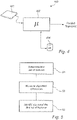
- the fingerprint sensor 102 and the operation for acquiring a fingerprint image is achieved using a conceptualized fingerprint sensor system 400 as is illustrated in Fig. 4 .
- the fingerprint sensor system 400 in turn, typically, forms part of the electronic device/mobile as is exemplified in Fig. 1 .
- the fingerprint sensor system 400 comprises the fingerprint sensor 102 and a processing circuitry, such as a control unit 402 for controlling the fingerprint sensor 102.
- the fingerprint sensor system 400 further comprises a memory, such as a database 404, e.g. storing a fingerprint template for the user.
- the control unit 402 may each include a microprocessor, microcontroller, programmable digital signal processor or another programmable device.
- the control unit 402 may also, or instead, each include an application specific integrated circuit, a programmable gate array or programmable array logic, a programmable logic device, or a digital signal processor.
- control unit 402 includes a programmable device such as the microprocessor, microcontroller or programmable digital signal processor mentioned above, the processor may further include computer executable code that controls operation of the programmable device. It should be understood that all or some parts of the functionality provided by means of the control unit 402 (or generally discussed as “processing circuitry”) may be at least partly integrated with the fingerprint sensor 402.
- control functionality of the present disclosure may be implemented using existing computer processors, or by a special purpose computer processor for an appropriate system, incorporated for this or another purpose, or by a hardwire system.
- Embodiments within the scope of the present disclosure include program products comprising machine-readable medium for carrying or having machine-executable instructions or data structures stored thereon.
- Such machine-readable media can be any available media that can be accessed by a general purpose or special purpose computer or other machine with a processor.
- machine-readable media can comprise RAM, ROM, EPROM, EEPROM, CD-ROM or other optical disk storage, magnetic disk storage or other magnetic storage devices, or any other medium which can be used to carry or store desired program code in the form of machine-executable instructions or data structures and which can be accessed by a general purpose or special purpose computer or other machine with a processor.
- a network or another communications connection either hardwired, wireless, or a combination of hardwired or wireless
- any such connection is properly termed a machine-readable medium.
- Machine-executable instructions include, for example, instructions and data which cause a general purpose computer, special purpose computer, or special purpose processing machines to perform a certain function or group of functions.
Landscapes
- Engineering & Computer Science (AREA)
- Theoretical Computer Science (AREA)
- Physics & Mathematics (AREA)
- General Physics & Mathematics (AREA)
- Multimedia (AREA)
- Human Computer Interaction (AREA)
- Computer Vision & Pattern Recognition (AREA)
- Health & Medical Sciences (AREA)
- Life Sciences & Earth Sciences (AREA)
- Artificial Intelligence (AREA)
- Data Mining & Analysis (AREA)
- Evolutionary Computation (AREA)
- Medical Informatics (AREA)
- General Health & Medical Sciences (AREA)
- Software Systems (AREA)
- Databases & Information Systems (AREA)
- Computing Systems (AREA)
- Bioinformatics & Cheminformatics (AREA)
- Bioinformatics & Computational Biology (AREA)
- Evolutionary Biology (AREA)
- General Engineering & Computer Science (AREA)
- Biomedical Technology (AREA)
- Public Health (AREA)
- Biophysics (AREA)
- Heart & Thoracic Surgery (AREA)
- Molecular Biology (AREA)
- Surgery (AREA)
- Animal Behavior & Ethology (AREA)
- Pathology (AREA)
- Veterinary Medicine (AREA)
- Computer Networks & Wireless Communication (AREA)
- Signal Processing (AREA)
- Image Input (AREA)
- Collating Specific Patterns (AREA)
- Measurement Of The Respiration, Hearing Ability, Form, And Blood Characteristics Of Living Organisms (AREA)
Description
- The present invention generally relates to a method for analyzing biometric measurements of a user, and specifically to determination of an alignment level between features of different biometric measurements acquired using a biometric sensor. The invention also relates to a fingerprint sensing system comprising a biometric sensor in the form of a fingerprint sensor.
- Various types of biometric systems are used more and more in order to provide an increased security for accessing an electronic device and at the same time keep the user convenience at an acceptable level. In particular fingerprint sensors have been successfully integrated in such devices, for example, thanks to their small form factor, high performance and user acceptance. Among the various available fingerprint sensing principles (such as capacitive, optical, thermal etc.), capacitive sensing is most commonly used, in particular in applications where size and power consumption are important.
- All capacitive fingerprint sensors provide an indicative measure of the capacitance between several sensing elements and a finger placed on the surface of the fingerprint sensor. Acquisition of a fingerprint image is typically performed using a fingerprint sensor comprising a plurality of sensing elements arranged in a two-dimensional manner, and a block based technique may be applied to the fingerprint sensor for acquiring a fingerprint image, where the blocks of sensing elements are sampled sequentially.
- One of the problems associated with fingerprint sensors concerns the presence of fixed patterns, resulting from the manufacturing of the fingerprint sensor or formed during use of the sensor, including for example scratches, etc. Such fixed patterns effectively result in degraded biometric performance.
- A special case is when fixed patterns are introduced after the enrollment phase and after the security level of the system has been determined. Due to the need to accommodate ageing of biometric traits, the fingerprint template will likely have to be updated over time. This leaves the system vulnerable to a fixed pattern being introduced into the biometric fingerprint template.
- In consequence, a lower than expected security level will result, since the matching process may recognize fixed pattern components in imposter attempts, thereby leading to a higher than expected false accept rate. Even without progressive updating of the fingerprint template, a fixed pattern may enter the template if the (genuine) user chooses to re-enroll. This re-enrollment may for example be triggered as a result of poor biometric performance due to the reduced similarity between the template and the identification samples, as the latter group now contains a fixed pattern in addition to fingerprint data.
- Attention is drawn to
WO 2007/050776 A2 , presenting biometrics system for capturing and processing a handprint image using a structured light illumination to create a 2D representation equivalent of a rolled inked handprint. - In view of above-mentioned problems with fixed patterns, it is an object of the present invention to provide an improved method for mitigating fixed patterns in biometric systems. In particular, the present inventors have found that it may be possible to take into account the alignment of features when comparing biometric measurements of a user, making use of an alignment level for identifying possible fixed patterns.
- According to an aspect of the present invention, it is therefore provided a method for analyzing biometric measurements of a user as defined by
claim 1. - The principal idea behind the invention resides in the unlikely scenario that a e.g. a body, face, hand, etc. of a user will be completely aligned in relation to e.g. a coordinate system of a biometric sensor when comparing subsequently acquired biometric measurements of the user, where the biometric measurements are acquired by means of the biometric sensor. In contrast, any fixed pattern will be well aligned across measurements. In accordance to the invention, features that are determined to "align too well" are identified as possible candidates relating to a fixed pattern at or adjacently to a surface the biometric sensor. It is worth noting that also the second set of features are arranged to have a location provided in relation to the biometric sensor.
- Rather than applying the prior art approach of discarding a full biometric measurement of the user in case only a small difference between subsequently acquired biometric measurements, the present invention goes further by allowing for a selection process to be implemented where only a sub-set of features identified as having an alignment difference being less than a threshold for example are discarded from further use. Such a solution for example improves the usability of a system implementing the inventive concept as more information may be used at each e.g. image acquisition. In addition, the security may be improvised by in fact allowing a user template to be dynamically updated during continuous use of the biometric sensing system.
- The removal of the sub-set of features may be applied to either or both of features relating to a currently acquired biometric measurement of a user (e.g. the first set of features) and to features relating to a further or previously acquired biometric measurement of the user (e.g. the second set of features). Accordingly, any set of features may be "purified" from possible fixed patterns.
- By means of the inventive concept it will be possible to reduce the number of false accepts (of imposters) caused by fixed pattern features. It will also be possible to preserve a low false rejection rate (of genuines) in a system applying the inventive concept without fixed patterns, i.e. by not degrade the basic identification performance as a result of fixed pattern protection. Furthermore, it will in accordance to the invention be possible to keep the false rejection rate (of genuines) low in a system contaminated with fixed patterns.
- Each feature of the first set of features further has an orientation provided in relation to the biometric sensor. That is, further information is be provided in relation to the features and used in measuring alignment differences, e.g. including how the feature is rotated in relation to the mentioned coordinate system of the biometric sensor.
- Furthermore, the identified alignment differences are tagged to the first set of features. Accordingly, rather than directly performing a process of removing e.g. the sub-set of the first set of features, the actual identified alignment differences may be stored for later use, e.g. in an authentication process.
- In accordance to the present disclosure, it should be understood that the matching threshold may be previously determined and/or set dynamically during operation of the biometric sensing system. For example, it may be possible to successively increase the matching threshold during use of the biometric sensing system, based on the expectation that an increased amount of fixed pattern could be present in relation to the surface of the biometric sensor. The matching threshold could in a possible embodiment not covered by the claimed invention be set differently depending on if the features are to be "appended" to a previously determined template for the user ("template update") or if the features are used in an authentication process. That is, the matching threshold may for example be set to be more secure in case of template update as compared to when performing the authentication process.
- The biometric system is further configured for allowing the authentication of the user. In such an implementation the method further includes the general determination of a matching level between the first set of features and the second set of features and comparing the matching level and a matching threshold, where the matching threshold may be dependent on the measuring alignment differences.
- The biometric sensing system is in accordance to the present disclosure a fingerprint sensing system and the biometric sensor is a fingerprint sensor, where the fingerprint sensor is configured to acquire a fingerprint image of the user. The second set of features may in such a case relate to a previously determined fingerprint template for the user, and the first set of features is determined based on e.g. a presently acquired fingerprint image.
- Within the context of the present disclosure, the expression "fingerprint image" should be interpreted broadly and to include both a regular "visual image" of a fingerprint of a finger as well as a set of measurements relating to the finger when acquired using the fingerprint sensor. A plurality of fingerprint images may be subsequently acquired and fused together, where the resulting information is used as an input for determining the sets of features.
- According to another aspect of the present invention, there is provided a fingerprint sensing system as defined by claim 4. This aspect of the invention provides similar advantages as discussed above in relation to the previous aspect of the invention. The expression "processing circuitry" should be understood to include any type of computing device, such as an ASIC, a micro-processor, etc. It should also be understood that the actual implementation of such a processing circuitry may be divided between more than a single device/circuit.
- The fingerprint sensor may, as indicated above, be implemented using any kind of current or future fingerprint sensing principle, including for example capacitive, optical, or thermal sensing technology. However, at present capacitive sensing is most preferred. Both one and two-dimensional sensors are possible and within the scope of the invention.
- The fingerprint sensing system preferably forms part of an electronic device further comprising a device controller for performing an authentication of the finger based on the at least one selected fingerprint image, and performing at least one action only if the authentication indicates an authentication success. Such an action may for example be for unlocking a locked portable device, e.g. in case the portable device is a mobile phone. The at least one action may of course be any type of action suitably used when there is a need to authenticate a finger.
- Further features of, and advantages with, the present invention will become apparent when studying the appended claims and the following description.
- The various aspects of the invention, including its particular features and advantages, will be readily understood from the following detailed description and the accompanying drawings, in which:
-
Figs. 1 schematically exemplify an electronic device according to the present invention, in the form of a mobile phone comprising an integrated fingerprint sensor; -
Fig. 2 schematically shows the fingerprint sensor array comprised in the electronic device inFig. 1 ; -
Figs. 3a - 3f show a conceptual flow of acquiring and purifying a fingerprint from a fixed pattern; -
Fig. 4 conceptually illustrates a fingerprint sensing system according to a currently preferred embodiment of the invention, and -
Fig. 5 is a flowchart disclosing the exemplary steps of the invention typically performed in conjunction with the fingerprint sensing system ofFig. 4 . - The present invention will now be described more fully hereinafter with reference to the accompanying drawings, in which currently preferred embodiments of the invention are shown.
- Turning now to the drawings and to
Fig 1 in particular, there is schematically illustrated the electronic device according to the present invention, in the form of a mobile phone 100 with anintegrated fingerprint sensor 102 and adisplay unit 104 with atouch screen interface 106. In this embodiment not covered by the claimed invention thefingerprint sensor 102 and thedisplay unit 104 are together arranged at the front side of the mobile phone 100. Thefingerprint sensor 102 may, for example, be used for unlocking the mobile phone 100 and/or for authorizing transactions carried out using the mobile phone 100, etc. Thefingerprint sensor 102 may of course also be placed on the backside of the mobile phone 100. - Preferably and as is apparent for the skilled person, the mobile phone 100 shown in
Fig. 1 further comprises a first antenna for WLAN/Wi-Fi communication, a second antenna for telecommunication communication, a microphone, a speaker, and a phone control unit. Further hardware elements are of course possibly comprised with the mobile phone. It should furthermore be noted that the invention may be applicable in relation to any other type of portable electronic device, such as a laptop, a remote control, a tablet computer, or any other type of present or future similarly configured device. - With reference to
Fig. 2 , there is conceptually illustrated a somewhat enlarged view of thefingerprint sensor 102. In the case of employing a capacitive sensing technology, thefingerprint sensor 102 is configured to comprise a large plurality of sensing elements, preferably arranged as a two-dimensional array. The two-dimensional array may have sizes depending on the planned implementation and in an embodiment not covered by the claimed invention 160x160 pixels are used. Other sizes are of course possible and within the scope of the invention, including two-dimensional array with less pixels as compared to the above example. A single sensing element (also denoted as a pixel) is inFig. 2 indicated byreference numeral 202. It should be understood that the invention may be applied to other types of sensors, for example provided in relation to vision system. In such a case a camera is typically included where e.g. a surface of a substrate/lens provided with the camera at a location facing e.g. a user/object may be provided with a fixed pattern. The camera may be arranged to capture e.g. a face or body part of a user to be subsequently used for identifying/authenticating the user. - Turning to
Figs. 3a - 3f in combination withFig. 5 , there is conceptually illustrated a possible implementation of the invention. The basic idea of the invention is to utilize the geometric alignment information between e.g. a fingerprint template for a user and a fingerprint sample used for identification/authentication of the user to assist in filtering out the fixed pattern in the pattern recognition process. Since a fixed pattern imposed onto e.g. thefingerprint sensor 102 will have fixed alignment to a reference coordinate system of thefingerprint sensor 102, whereas the fingerprint sample of interest generally will not, this property can be exploited to help separate what is fingerprint sample data of interest and what is not. - Specifically, in
Fig. 3a there is illustrated an example of a "top surface" (e.g. coating) of afingerprint sensor 102. A plurality ofscratches 300 has been introduced at the top surface during normal use of thefingerprint sensor 102, e.g. when the portable electronic device comprising thefingerprint sensor 102 has been placed in a pocket/bag of the user. It should be understood that the fixed pattern,e.g. scratches 300, possibly could be deliberately introduced or inherent from the manufacturing of thefingerprint sensor 102. - When activating the
fingerprint sensor 102 for acquiring a fingerprint image, as seen inFig. 3b , the user will position his finger at or adjacently to the top surface of thefingerprint sensor 102 at a first random relative angle α1 as compared to thefingerprint sensor 102. Thescratches 300 will accordingly be captured by thefingerprint sensor 102 along with friction ridges of the finger, the friction ridges of the finger representing the "real" fingerprint for the user. The digital representation of the friction ridges of the finger of the user at the first random relative angle α1 combined with thescratches 300 at the surface of thesensor 102 are shown inFig. 3c as a first distortedfingerprint image 302. - In a prior art solution, the distorted
fingerprint image 302 will form an input for all subsequent image analysis, feature extraction, authentication, etc. Accordingly, also the scratches will be taken as being part of the users fingerprint. However, in accordance to the invention, a first set of features being a representation of and determined, S1, from the distortedfingerprint image 302 are compared to a second set of features. It should be understood that each feature of the first set of features are defined to have a location and possibly a rotation provided in relation to thefingerprint sensor 102. The second set of features may for example be determined from a second fingerprint image, or be part of e.g. a previously determined fingerprint template for the user. - In the illustration provided in
Fig. 3d , the second set of features are formed by the user again, e.g. at a later stage, positioning his finger at thefingerprint sensor 102 at a second random relative angle α2 as compared to thefingerprint sensor 102. InFig. 3d the finger is slightly rotated as compared to the finger shown inFig. 3b . In accordance to the invention, the first relative angle α1 and the second relative angle α2 are during normal use not expected to be the same, i.e. at least a small amount of misalignment is expected between the different times of the user positioning his finger at thefingerprint sensor 102. In comparingFigs. 3b and 3d only a small rotation is illustrated, a small translation of the position of the finger of the user is of course possible/likely. The digital representation of the friction ridges of the finger of the user at the second random relative angle α2 combined with thescratches 300 at the surface of thesensor 102 are shown inFig. 3e as a second distortedfingerprint image 304. - By means of the invention, alignment differences are measured, S2, the measurements made between the locations of the first set of features and the features of the second set of features. As is understood from the above, the features of the first and the second set of features relating to the scratches will have essentially (or identically) the same location (and possibly rotation) as compared to e.g. the reference coordinate system of the
fingerprint sensor 102. - In the illustration provided in
Fig. 3f , the first set of features relating to the first distortedfingerprint image 302 have been compared to the second set of features relating to the second distortedfingerprint image 304. In accordance to the invention, a sub-set of features having alignment differences being "too small", being smaller than a threshold, are extracted out and identified, S3, as possibly being part of the fixed pattern, e.g. conceptually illustrated as thescratches 300, at the surface of thefingerprint sensor 102. - The identified sub-set of features may for example be filtered out from the first 302 and/or the second 304 distorted fingerprint images, thus forming a purified fingerprint image. The information may alternatively be used within a matching process, possibly allowing for a higher matching threshold if an in comparison large amount of fixed pattern has been identified.
- In a possible embodiment not covered by the claimed invention, it may be of interest to allow for a fingerprint template for the user to be "continuously" updated during use, for allowing small changes to the fingerprint of the user to be accounted for. It is undesirable to introduce a fixed pattern with such an updated fingerprint template. Thus, it may in accordance to the invention be possible to check that a given feature from a first fingerprint image can be found in another fingerprint image with a non-identity transform (i.e. "enough misalignment"), before the feature is allowed to be admitted into the template. This constraint to template updating should also allow for an improved safety of a system comprising the disclosed solution as e.g. an intentionally introduced fixed pattern (e.g. by a potential imposter) will be identified and accordingly not allowed to be introduced with any updated fingerprint templates.
- In the above presentation of the invention it is stated that the identification of the possible fixed pattern is done when the alignment difference is less than a threshold. The threshold could be predetermined or be continuously updated. The threshold could also be dependent on if it previously has been determined that a fixed pattern is present at the
fingerprint sensor 102. The threshold may also in some implementations be allowed to be set by the user, e.g. for improved security/safety of the system comprising thefingerprint sensor 102. - In accordance with the invention, the
fingerprint sensor 102 and the operation for acquiring a fingerprint image is achieved using a conceptualizedfingerprint sensor system 400 as is illustrated inFig. 4 . Thefingerprint sensor system 400 in turn, typically, forms part of the electronic device/mobile as is exemplified inFig. 1 . - The
fingerprint sensor system 400 comprises thefingerprint sensor 102 and a processing circuitry, such as acontrol unit 402 for controlling thefingerprint sensor 102. Thefingerprint sensor system 400 further comprises a memory, such as adatabase 404, e.g. storing a fingerprint template for the user. Thecontrol unit 402 may each include a microprocessor, microcontroller, programmable digital signal processor or another programmable device. Thecontrol unit 402 may also, or instead, each include an application specific integrated circuit, a programmable gate array or programmable array logic, a programmable logic device, or a digital signal processor. Where thecontrol unit 402 includes a programmable device such as the microprocessor, microcontroller or programmable digital signal processor mentioned above, the processor may further include computer executable code that controls operation of the programmable device. It should be understood that all or some parts of the functionality provided by means of the control unit 402 (or generally discussed as "processing circuitry") may be at least partly integrated with thefingerprint sensor 402. - The control functionality of the present disclosure may be implemented using existing computer processors, or by a special purpose computer processor for an appropriate system, incorporated for this or another purpose, or by a hardwire system. Embodiments within the scope of the present disclosure include program products comprising machine-readable medium for carrying or having machine-executable instructions or data structures stored thereon. Such machine-readable media can be any available media that can be accessed by a general purpose or special purpose computer or other machine with a processor. By way of example, such machine-readable media can comprise RAM, ROM, EPROM, EEPROM, CD-ROM or other optical disk storage, magnetic disk storage or other magnetic storage devices, or any other medium which can be used to carry or store desired program code in the form of machine-executable instructions or data structures and which can be accessed by a general purpose or special purpose computer or other machine with a processor. When information is transferred or provided over a network or another communications connection (either hardwired, wireless, or a combination of hardwired or wireless) to a machine, the machine properly views the connection as a machine-readable medium. Thus, any such connection is properly termed a machine-readable medium. Combinations of the above are also included within the scope of machine-readable media. Machine-executable instructions include, for example, instructions and data which cause a general purpose computer, special purpose computer, or special purpose processing machines to perform a certain function or group of functions.
- Although the figures may show a sequence the order of the steps may differ from what is depicted. Also two or more steps may be performed concurrently or with partial concurrence. Such variation will depend on the software and hardware systems chosen and on designer choice. All such variations are within the scope of the disclosure. Likewise, software implementations could be accomplished with standard programming techniques with rule based logic and other logic to accomplish the various connection steps, processing steps, comparison steps and decision steps. Additionally, in the claims, the word "comprising" does not exclude other elements or steps, and the indefinite article "a" or "an" does not exclude a plurality.
Claims (7)
- A computer-implemented method for fingerprint analysis of a finger of a user by means of a fingerprint sensing system (400), the fingerprint sensing system (400) comprising:- a fingerprint sensor (102) having a reference coordinate system, and- processing circuitry (402) connected to the fingerprint sensor,wherein the method comprises the steps of:- acquiring a first fingerprint image using the fingerprint sensor when the finger of the user is placed at a surface of the fingerprint sensor at a first relative angle with respect to an axis of the reference coordinate system;- determining (S1) a first set of features from the first fingerprint image, each feature of the first set of features having a location and an orientation represented by coordinates provided in relation to the reference coordinate system of the fingerprint sensor;- acquiring a second fingerprint image using the fingerprint sensor when the finger of the user is placed at the surface of the fingerprint sensor at a second relative angle with respect to the axis of the reference coordinate system, the second relative angle being different from the first relative angle, wherein the second fingerprint image is acquired prior to acquiring the first fingerprint image;- determining a second set of features from the second fingerprint image, each feature of the second set of features having a location and an orientation represented by coordinates provided in relation to the reference coordinate system of the fingerprint sensor;- measuring (S2) alignment differences in the reference coordinate system between the locations and orientations of features of the first set of features and locations and orientations of corresponding features of the second set of features;- identifying (S3) a sub-set of the first set of features, the sub-set containing features having an alignment difference less than a threshold, wherein features of the sub-set possibly represent a fixed pattern at or adjacent to the surface of the fingerprint sensor, and- removing the sub-set from the first set of features,wherein the method is further adapted to authenticate the user by the steps of:- determining a matching level between the first set of features and the second set of features, wherein the sub-set has been removed from the first set of features; and- comparing the matching level with a matching threshold.
- The method according to claim 1, further comprising determining a summarized value for the measured alignment differences.
- The method according to claim 2, wherein the summarized value is a weighted summarized value.
- A fingerprint sensing system (400), comprising:- a fingerprint sensor (102) having a reference coordinate system;- a memory (404); and- processing circuitry (402) connected to the fingerprint sensor for:wherein the processing circuitry is further adapted to authenticate the user by:- acquiring a first fingerprint image using the fingerprint sensor when a finger of a user is placed at a surface of the fingerprint sensor at a first relative angle with respect to an axis of the reference coordinate system;- determining a first set of features from the first fingerprint image, each feature of the first set of features having a location and an orientation represented by coordinates provided in relation to the reference coordinate system of the fingerprint sensor;- acquiring a second fingerprint image using the fingerprint sensor when the finger of the user is placed at the surface of the fingerprint sensor at a second relative angle with respect to the axis of the reference coordinate system, the second relative angle being different from the first relative angle, wherein the second fingerprint image is acquired prior to acquiring the first fingerprint image;- determining a second set of features from the second fingerprint image, each feature of the second set of features having a location and an orientation represented by coordinates provided in relation to the reference coordinate system of the fingerprint sensor;- measuring alignment differences in the reference coordinate system between the locations and orientations of features of the first set of features and locations and orientations of the corresponding features of the second set of features;- identifying a sub-set of the first set of features, the sub-set of features having an alignment difference less than a threshold, wherein features of the sub-set possibly represent a candidate of a fixed pattern at or adjacent to the surface of the fingerprint sensor, and- removing the sub-set from the first set of features,- determining a matching level between the first set of features and the second set of features, wherein the sub-set has been removed from the first set of features; and- comparing the matching level with a matching threshold.
- The fingerprint sensing system according to claim 4, wherein the fingerprint sensor is a capacitive fingerprint sensor.
- An electronic device (100), comprising the fingerprint sensing system according to claim 4.
- The electronic device according to claim 6, wherein the electronic device is a mobile phone.
Applications Claiming Priority (2)
| Application Number | Priority Date | Filing Date | Title |
|---|---|---|---|
| SE1650126A SE1650126A1 (en) | 2016-02-02 | 2016-02-02 | Method and fingerprint sensing system for analyzing biometric measurements of a user |
| PCT/SE2017/050069 WO2017135869A1 (en) | 2016-02-02 | 2017-01-26 | Method and fingerprint sensing system for analyzing biometric measurements of a user |
Publications (3)
| Publication Number | Publication Date |
|---|---|
| EP3411830A1 EP3411830A1 (en) | 2018-12-12 |
| EP3411830A4 EP3411830A4 (en) | 2019-09-04 |
| EP3411830B1 true EP3411830B1 (en) | 2022-11-23 |
Family
ID=59386891
Family Applications (1)
| Application Number | Title | Priority Date | Filing Date |
|---|---|---|---|
| EP17747870.8A Active EP3411830B1 (en) | 2016-02-02 | 2017-01-26 | Fingerprint sensing method and system for analyzing biometric measurements of a user |
Country Status (7)
| Country | Link |
|---|---|
| US (1) | US10268873B2 (en) |
| EP (1) | EP3411830B1 (en) |
| JP (1) | JP7079730B2 (en) |
| KR (1) | KR20180108628A (en) |
| CN (1) | CN107408208B (en) |
| SE (1) | SE1650126A1 (en) |
| WO (1) | WO2017135869A1 (en) |
Families Citing this family (4)
| Publication number | Priority date | Publication date | Assignee | Title |
|---|---|---|---|---|
| US10122764B1 (en) * | 2017-04-25 | 2018-11-06 | T-Mobile Usa, Inc. | Multi-factor and context sensitive biometric authentication system |
| US12019719B2 (en) * | 2018-06-19 | 2024-06-25 | Fingerprint Cards Anacatum Ip Ab | Method and electronic device for authenticating a user |
| US11216541B2 (en) * | 2018-09-07 | 2022-01-04 | Qualcomm Incorporated | User adaptation for biometric authentication |
| CN109313705B (en) * | 2018-09-12 | 2021-10-08 | 深圳市汇顶科技股份有限公司 | Fingerprint identification method, device, equipment and storage medium |
Citations (1)
| Publication number | Priority date | Publication date | Assignee | Title |
|---|---|---|---|---|
| US8631243B2 (en) * | 2007-12-24 | 2014-01-14 | Telecom Italia S.P.A. | Biometrics based identification |
Family Cites Families (21)
| Publication number | Priority date | Publication date | Assignee | Title |
|---|---|---|---|---|
| US6125192A (en) * | 1997-04-21 | 2000-09-26 | Digital Persona, Inc. | Fingerprint recognition system |
| US6535622B1 (en) * | 1999-04-26 | 2003-03-18 | Veridicom, Inc. | Method for imaging fingerprints and concealing latent fingerprints |
| US7369688B2 (en) * | 2001-05-09 | 2008-05-06 | Nanyang Technological Univeristy | Method and device for computer-based processing a template minutia set of a fingerprint and a computer readable storage medium |
| US7203347B2 (en) * | 2001-06-27 | 2007-04-10 | Activcard Ireland Limited | Method and system for extracting an area of interest from within a swipe image of a biological surface |
| FR2829264A1 (en) * | 2001-09-04 | 2003-03-07 | St Microelectronics Sa | METHOD OF COMPARING FINGERPRINTS |
| US7142699B2 (en) * | 2001-12-14 | 2006-11-28 | Siemens Corporate Research, Inc. | Fingerprint matching using ridge feature maps |
| US7355690B2 (en) * | 2003-07-21 | 2008-04-08 | Applied Materials, Israel, Ltd. | Double inspection of reticle or wafer |
| US7915601B2 (en) * | 2003-09-05 | 2011-03-29 | Authentec, Inc. | Electronic device including optical dispersion finger sensor and associated methods |
| JP4592341B2 (en) | 2004-06-29 | 2010-12-01 | セコム株式会社 | Biometric authentication device |
| US20080298646A1 (en) * | 2005-01-31 | 2008-12-04 | Precise Biometrics Ab | Method and Device for Improved Fingerprint Matching |
| WO2007050776A2 (en) | 2005-10-25 | 2007-05-03 | University Of Kentucky Research Foundation | System and method for 3d imaging using structured light illumination |
| JP2007323433A (en) | 2006-06-01 | 2007-12-13 | Sharp Corp | Image processing apparatus, image processing method, image processing program, and computer-readable recording medium on which image processing program is recorded |
| JP4427039B2 (en) | 2006-08-18 | 2010-03-03 | 富士通株式会社 | Biometric information acquisition apparatus and biometric information authentication apparatus |
| US20100080425A1 (en) * | 2008-09-29 | 2010-04-01 | Board of regents of the Nevada System of Higher Education, on Behalf of the University of | Minutiae-based template synthesis and matching |
| US20130173925A1 (en) * | 2011-12-28 | 2013-07-04 | Ester Yen | Systems and Methods for Fingerprint-Based Operations |
| US8953854B2 (en) * | 2012-08-08 | 2015-02-10 | The Hong Kong Polytechnic University | Contactless 3D biometric feature identification system and method thereof |
| GB2507540A (en) * | 2012-11-02 | 2014-05-07 | Zwipe As | Enrolling fingerprints by combining image strips to obtain sufficient width |
| US10068120B2 (en) * | 2013-03-15 | 2018-09-04 | Apple Inc. | High dynamic range fingerprint sensing |
| KR101432011B1 (en) | 2013-03-22 | 2014-08-21 | 주식회사 슈프리마 | Apparatus and method for processing fingerprint image |
| KR102257287B1 (en) * | 2014-08-07 | 2021-05-27 | 삼성전자주식회사 | Method and apparatus for authenticating user using fingerprint and ecg signal |
| JP6101723B2 (en) | 2015-03-23 | 2017-03-22 | 株式会社日立製作所 | Personal authentication apparatus and method |
-
2016
- 2016-02-02 SE SE1650126A patent/SE1650126A1/en not_active Application Discontinuation
-
2017
- 2017-01-26 KR KR1020187022002A patent/KR20180108628A/en not_active Withdrawn
- 2017-01-26 EP EP17747870.8A patent/EP3411830B1/en active Active
- 2017-01-26 CN CN201780001067.9A patent/CN107408208B/en active Active
- 2017-01-26 WO PCT/SE2017/050069 patent/WO2017135869A1/en not_active Ceased
- 2017-01-26 JP JP2018539958A patent/JP7079730B2/en active Active
- 2017-01-30 US US15/418,874 patent/US10268873B2/en active Active
Patent Citations (1)
| Publication number | Priority date | Publication date | Assignee | Title |
|---|---|---|---|---|
| US8631243B2 (en) * | 2007-12-24 | 2014-01-14 | Telecom Italia S.P.A. | Biometrics based identification |
Also Published As
| Publication number | Publication date |
|---|---|
| EP3411830A4 (en) | 2019-09-04 |
| SE1650126A1 (en) | 2017-08-03 |
| JP7079730B2 (en) | 2022-06-02 |
| US20170220845A1 (en) | 2017-08-03 |
| CN107408208B (en) | 2020-05-29 |
| KR20180108628A (en) | 2018-10-04 |
| EP3411830A1 (en) | 2018-12-12 |
| JP2019503545A (en) | 2019-02-07 |
| CN107408208A (en) | 2017-11-28 |
| WO2017135869A1 (en) | 2017-08-10 |
| US10268873B2 (en) | 2019-04-23 |
Similar Documents
| Publication | Publication Date | Title |
|---|---|---|
| US11216546B2 (en) | Method for fingerprint authentication using force value | |
| US11527103B2 (en) | Auxtiliary filtering device of electronic device and cellphone | |
| JP2017533516A (en) | Fingerprint authentication using stitching and cutting | |
| CN106796660A (en) | Method and fingerprint sensing system for forming fingerprint representation | |
| US10268873B2 (en) | Method and fingerprint sensing system for analyzing biometric measurements of a user | |
| JP2009230459A (en) | Authentication device and authentication system | |
| KR20090016892A (en) | Fingerprint reader and method | |
| CN105913264B (en) | Face payment device based on fingerprint assisted identification | |
| CN105787416A (en) | Mobile terminal-based face recognition method and system | |
| WO2017146638A1 (en) | Method and system for controlling an electronic device | |
| JP5773739B2 (en) | Verification device | |
| US11301706B2 (en) | Method of authenticating a user | |
| WO2019109322A1 (en) | Biometric feature detection method and identification system | |
| US11366887B2 (en) | Biometric authentication | |
| CN101241526A (en) | Palm moving electronic device image identification authentication method | |
| US11823487B2 (en) | Method and system for enrolling a fingerprint | |
| EP2833627A1 (en) | Information processing device, information processing method and program | |
| US11544961B2 (en) | Passive three-dimensional face imaging based on macro-structure and micro-structure image sizing | |
| SE1950088A1 (en) | A method for updating a biometric template and an electronic device thereof | |
| CN107437053A (en) | A kind of fingerprint identification method and device |
Legal Events
| Date | Code | Title | Description |
|---|---|---|---|
| STAA | Information on the status of an ep patent application or granted ep patent |
Free format text: STATUS: THE INTERNATIONAL PUBLICATION HAS BEEN MADE |
|
| PUAI | Public reference made under article 153(3) epc to a published international application that has entered the european phase |
Free format text: ORIGINAL CODE: 0009012 |
|
| STAA | Information on the status of an ep patent application or granted ep patent |
Free format text: STATUS: REQUEST FOR EXAMINATION WAS MADE |
|
| 17P | Request for examination filed |
Effective date: 20180823 |
|
| AK | Designated contracting states |
Kind code of ref document: A1 Designated state(s): AL AT BE BG CH CY CZ DE DK EE ES FI FR GB GR HR HU IE IS IT LI LT LU LV MC MK MT NL NO PL PT RO RS SE SI SK SM TR |
|
| AX | Request for extension of the european patent |
Extension state: BA ME |
|
| RIN1 | Information on inventor provided before grant (corrected) |
Inventor name: STEGMANN, MIKKEL B. Inventor name: HANSEN, MICHAEL SASS Inventor name: CHRISTENSEN, LARS Inventor name: CHRISTENSEN, SOEREN SKOVGAARD |
|
| DAV | Request for validation of the european patent (deleted) | ||
| DAX | Request for extension of the european patent (deleted) | ||
| A4 | Supplementary search report drawn up and despatched |
Effective date: 20190806 |
|
| RIC1 | Information provided on ipc code assigned before grant |
Ipc: G06K 9/62 20060101ALI20190731BHEP Ipc: G06K 9/00 20060101AFI20190731BHEP |
|
| STAA | Information on the status of an ep patent application or granted ep patent |
Free format text: STATUS: EXAMINATION IS IN PROGRESS |
|
| 17Q | First examination report despatched |
Effective date: 20200507 |
|
| RAP1 | Party data changed (applicant data changed or rights of an application transferred) |
Owner name: FINGERPRINT CARDS ANACATUM IP AB |
|
| REG | Reference to a national code |
Ref country code: DE Ref legal event code: R079 Ref document number: 602017063931 Country of ref document: DE Free format text: PREVIOUS MAIN CLASS: G06K0009340000 Ipc: G06K0009620000 |
|
| GRAP | Despatch of communication of intention to grant a patent |
Free format text: ORIGINAL CODE: EPIDOSNIGR1 |
|
| STAA | Information on the status of an ep patent application or granted ep patent |
Free format text: STATUS: GRANT OF PATENT IS INTENDED |
|
| RIC1 | Information provided on ipc code assigned before grant |
Ipc: G06V 40/13 20220101ALI20220614BHEP Ipc: G06V 40/12 20220101ALI20220614BHEP Ipc: G06K 9/62 20060101AFI20220614BHEP |
|
| INTG | Intention to grant announced |
Effective date: 20220630 |
|
| GRAS | Grant fee paid |
Free format text: ORIGINAL CODE: EPIDOSNIGR3 |
|
| GRAA | (expected) grant |
Free format text: ORIGINAL CODE: 0009210 |
|
| STAA | Information on the status of an ep patent application or granted ep patent |
Free format text: STATUS: THE PATENT HAS BEEN GRANTED |
|
| AK | Designated contracting states |
Kind code of ref document: B1 Designated state(s): AL AT BE BG CH CY CZ DE DK EE ES FI FR GB GR HR HU IE IS IT LI LT LU LV MC MK MT NL NO PL PT RO RS SE SI SK SM TR |
|
| REG | Reference to a national code |
Ref country code: GB Ref legal event code: FG4D |
|
| REG | Reference to a national code |
Ref country code: DE Ref legal event code: R079 Ref document number: 602017063931 Country of ref document: DE Free format text: PREVIOUS MAIN CLASS: G06K0009620000 Ipc: G06V0030190000 |
|
| REG | Reference to a national code |
Ref country code: CH Ref legal event code: EP |
|
| REG | Reference to a national code |
Ref country code: DE Ref legal event code: R096 Ref document number: 602017063931 Country of ref document: DE |
|
| REG | Reference to a national code |
Ref country code: AT Ref legal event code: REF Ref document number: 1533599 Country of ref document: AT Kind code of ref document: T Effective date: 20221215 |
|
| REG | Reference to a national code |
Ref country code: IE Ref legal event code: FG4D |
|
| REG | Reference to a national code |
Ref country code: LT Ref legal event code: MG9D |
|
| REG | Reference to a national code |
Ref country code: NL Ref legal event code: MP Effective date: 20221123 |
|
| REG | Reference to a national code |
Ref country code: AT Ref legal event code: MK05 Ref document number: 1533599 Country of ref document: AT Kind code of ref document: T Effective date: 20221123 |
|
| PG25 | Lapsed in a contracting state [announced via postgrant information from national office to epo] |
Ref country code: SE Free format text: LAPSE BECAUSE OF FAILURE TO SUBMIT A TRANSLATION OF THE DESCRIPTION OR TO PAY THE FEE WITHIN THE PRESCRIBED TIME-LIMIT Effective date: 20221123 Ref country code: PT Free format text: LAPSE BECAUSE OF FAILURE TO SUBMIT A TRANSLATION OF THE DESCRIPTION OR TO PAY THE FEE WITHIN THE PRESCRIBED TIME-LIMIT Effective date: 20230323 Ref country code: NO Free format text: LAPSE BECAUSE OF FAILURE TO SUBMIT A TRANSLATION OF THE DESCRIPTION OR TO PAY THE FEE WITHIN THE PRESCRIBED TIME-LIMIT Effective date: 20230223 Ref country code: LT Free format text: LAPSE BECAUSE OF FAILURE TO SUBMIT A TRANSLATION OF THE DESCRIPTION OR TO PAY THE FEE WITHIN THE PRESCRIBED TIME-LIMIT Effective date: 20221123 Ref country code: FI Free format text: LAPSE BECAUSE OF FAILURE TO SUBMIT A TRANSLATION OF THE DESCRIPTION OR TO PAY THE FEE WITHIN THE PRESCRIBED TIME-LIMIT Effective date: 20221123 Ref country code: ES Free format text: LAPSE BECAUSE OF FAILURE TO SUBMIT A TRANSLATION OF THE DESCRIPTION OR TO PAY THE FEE WITHIN THE PRESCRIBED TIME-LIMIT Effective date: 20221123 Ref country code: AT Free format text: LAPSE BECAUSE OF FAILURE TO SUBMIT A TRANSLATION OF THE DESCRIPTION OR TO PAY THE FEE WITHIN THE PRESCRIBED TIME-LIMIT Effective date: 20221123 |
|
| PG25 | Lapsed in a contracting state [announced via postgrant information from national office to epo] |
Ref country code: RS Free format text: LAPSE BECAUSE OF FAILURE TO SUBMIT A TRANSLATION OF THE DESCRIPTION OR TO PAY THE FEE WITHIN THE PRESCRIBED TIME-LIMIT Effective date: 20221123 Ref country code: PL Free format text: LAPSE BECAUSE OF FAILURE TO SUBMIT A TRANSLATION OF THE DESCRIPTION OR TO PAY THE FEE WITHIN THE PRESCRIBED TIME-LIMIT Effective date: 20221123 Ref country code: LV Free format text: LAPSE BECAUSE OF FAILURE TO SUBMIT A TRANSLATION OF THE DESCRIPTION OR TO PAY THE FEE WITHIN THE PRESCRIBED TIME-LIMIT Effective date: 20221123 Ref country code: IS Free format text: LAPSE BECAUSE OF FAILURE TO SUBMIT A TRANSLATION OF THE DESCRIPTION OR TO PAY THE FEE WITHIN THE PRESCRIBED TIME-LIMIT Effective date: 20230323 Ref country code: HR Free format text: LAPSE BECAUSE OF FAILURE TO SUBMIT A TRANSLATION OF THE DESCRIPTION OR TO PAY THE FEE WITHIN THE PRESCRIBED TIME-LIMIT Effective date: 20221123 Ref country code: GR Free format text: LAPSE BECAUSE OF FAILURE TO SUBMIT A TRANSLATION OF THE DESCRIPTION OR TO PAY THE FEE WITHIN THE PRESCRIBED TIME-LIMIT Effective date: 20230224 |
|
| PG25 | Lapsed in a contracting state [announced via postgrant information from national office to epo] |
Ref country code: NL Free format text: LAPSE BECAUSE OF FAILURE TO SUBMIT A TRANSLATION OF THE DESCRIPTION OR TO PAY THE FEE WITHIN THE PRESCRIBED TIME-LIMIT Effective date: 20221123 |
|
| PG25 | Lapsed in a contracting state [announced via postgrant information from national office to epo] |
Ref country code: SM Free format text: LAPSE BECAUSE OF FAILURE TO SUBMIT A TRANSLATION OF THE DESCRIPTION OR TO PAY THE FEE WITHIN THE PRESCRIBED TIME-LIMIT Effective date: 20221123 Ref country code: RO Free format text: LAPSE BECAUSE OF FAILURE TO SUBMIT A TRANSLATION OF THE DESCRIPTION OR TO PAY THE FEE WITHIN THE PRESCRIBED TIME-LIMIT Effective date: 20221123 Ref country code: EE Free format text: LAPSE BECAUSE OF FAILURE TO SUBMIT A TRANSLATION OF THE DESCRIPTION OR TO PAY THE FEE WITHIN THE PRESCRIBED TIME-LIMIT Effective date: 20221123 Ref country code: DK Free format text: LAPSE BECAUSE OF FAILURE TO SUBMIT A TRANSLATION OF THE DESCRIPTION OR TO PAY THE FEE WITHIN THE PRESCRIBED TIME-LIMIT Effective date: 20221123 Ref country code: CZ Free format text: LAPSE BECAUSE OF FAILURE TO SUBMIT A TRANSLATION OF THE DESCRIPTION OR TO PAY THE FEE WITHIN THE PRESCRIBED TIME-LIMIT Effective date: 20221123 |
|
| REG | Reference to a national code |
Ref country code: DE Ref legal event code: R097 Ref document number: 602017063931 Country of ref document: DE |
|
| PG25 | Lapsed in a contracting state [announced via postgrant information from national office to epo] |
Ref country code: SK Free format text: LAPSE BECAUSE OF FAILURE TO SUBMIT A TRANSLATION OF THE DESCRIPTION OR TO PAY THE FEE WITHIN THE PRESCRIBED TIME-LIMIT Effective date: 20221123 Ref country code: AL Free format text: LAPSE BECAUSE OF FAILURE TO SUBMIT A TRANSLATION OF THE DESCRIPTION OR TO PAY THE FEE WITHIN THE PRESCRIBED TIME-LIMIT Effective date: 20221123 |
|
| REG | Reference to a national code |
Ref country code: CH Ref legal event code: PL |
|
| PG25 | Lapsed in a contracting state [announced via postgrant information from national office to epo] |
Ref country code: LU Free format text: LAPSE BECAUSE OF NON-PAYMENT OF DUE FEES Effective date: 20230126 |
|
| PLBE | No opposition filed within time limit |
Free format text: ORIGINAL CODE: 0009261 |
|
| STAA | Information on the status of an ep patent application or granted ep patent |
Free format text: STATUS: NO OPPOSITION FILED WITHIN TIME LIMIT |
|
| REG | Reference to a national code |
Ref country code: BE Ref legal event code: MM Effective date: 20230131 |
|
| PG25 | Lapsed in a contracting state [announced via postgrant information from national office to epo] |
Ref country code: LI Free format text: LAPSE BECAUSE OF NON-PAYMENT OF DUE FEES Effective date: 20230131 Ref country code: CH Free format text: LAPSE BECAUSE OF NON-PAYMENT OF DUE FEES Effective date: 20230131 |
|
| 26N | No opposition filed |
Effective date: 20230824 |
|
| PG25 | Lapsed in a contracting state [announced via postgrant information from national office to epo] |
Ref country code: SI Free format text: LAPSE BECAUSE OF FAILURE TO SUBMIT A TRANSLATION OF THE DESCRIPTION OR TO PAY THE FEE WITHIN THE PRESCRIBED TIME-LIMIT Effective date: 20221123 Ref country code: BE Free format text: LAPSE BECAUSE OF NON-PAYMENT OF DUE FEES Effective date: 20230131 |
|
| PG25 | Lapsed in a contracting state [announced via postgrant information from national office to epo] |
Ref country code: IE Free format text: LAPSE BECAUSE OF NON-PAYMENT OF DUE FEES Effective date: 20230126 |
|
| PG25 | Lapsed in a contracting state [announced via postgrant information from national office to epo] |
Ref country code: IT Free format text: LAPSE BECAUSE OF FAILURE TO SUBMIT A TRANSLATION OF THE DESCRIPTION OR TO PAY THE FEE WITHIN THE PRESCRIBED TIME-LIMIT Effective date: 20221123 |
|
| PG25 | Lapsed in a contracting state [announced via postgrant information from national office to epo] |
Ref country code: MC Free format text: LAPSE BECAUSE OF FAILURE TO SUBMIT A TRANSLATION OF THE DESCRIPTION OR TO PAY THE FEE WITHIN THE PRESCRIBED TIME-LIMIT Effective date: 20221123 |
|
| PG25 | Lapsed in a contracting state [announced via postgrant information from national office to epo] |
Ref country code: MC Free format text: LAPSE BECAUSE OF FAILURE TO SUBMIT A TRANSLATION OF THE DESCRIPTION OR TO PAY THE FEE WITHIN THE PRESCRIBED TIME-LIMIT Effective date: 20221123 |
|
| PG25 | Lapsed in a contracting state [announced via postgrant information from national office to epo] |
Ref country code: BG Free format text: LAPSE BECAUSE OF FAILURE TO SUBMIT A TRANSLATION OF THE DESCRIPTION OR TO PAY THE FEE WITHIN THE PRESCRIBED TIME-LIMIT Effective date: 20221123 |
|
| PG25 | Lapsed in a contracting state [announced via postgrant information from national office to epo] |
Ref country code: BG Free format text: LAPSE BECAUSE OF FAILURE TO SUBMIT A TRANSLATION OF THE DESCRIPTION OR TO PAY THE FEE WITHIN THE PRESCRIBED TIME-LIMIT Effective date: 20221123 |
|
| PG25 | Lapsed in a contracting state [announced via postgrant information from national office to epo] |
Ref country code: CY Free format text: LAPSE BECAUSE OF FAILURE TO SUBMIT A TRANSLATION OF THE DESCRIPTION OR TO PAY THE FEE WITHIN THE PRESCRIBED TIME-LIMIT; INVALID AB INITIO Effective date: 20170126 |
|
| PG25 | Lapsed in a contracting state [announced via postgrant information from national office to epo] |
Ref country code: HU Free format text: LAPSE BECAUSE OF FAILURE TO SUBMIT A TRANSLATION OF THE DESCRIPTION OR TO PAY THE FEE WITHIN THE PRESCRIBED TIME-LIMIT; INVALID AB INITIO Effective date: 20170126 |
|
| PG25 | Lapsed in a contracting state [announced via postgrant information from national office to epo] |
Ref country code: TR Free format text: LAPSE BECAUSE OF FAILURE TO SUBMIT A TRANSLATION OF THE DESCRIPTION OR TO PAY THE FEE WITHIN THE PRESCRIBED TIME-LIMIT Effective date: 20221123 |
|
| PGFP | Annual fee paid to national office [announced via postgrant information from national office to epo] |
Ref country code: GB Payment date: 20260127 Year of fee payment: 10 |
|
| PGFP | Annual fee paid to national office [announced via postgrant information from national office to epo] |
Ref country code: DE Payment date: 20260128 Year of fee payment: 10 |
|
| PGFP | Annual fee paid to national office [announced via postgrant information from national office to epo] |
Ref country code: FR Payment date: 20260126 Year of fee payment: 10 |