EP3411536B1 - Apparatus for flushing a toilet, comprising an accumulator - Google Patents
Apparatus for flushing a toilet, comprising an accumulator Download PDFInfo
- Publication number
- EP3411536B1 EP3411536B1 EP17704060.7A EP17704060A EP3411536B1 EP 3411536 B1 EP3411536 B1 EP 3411536B1 EP 17704060 A EP17704060 A EP 17704060A EP 3411536 B1 EP3411536 B1 EP 3411536B1
- Authority
- EP
- European Patent Office
- Prior art keywords
- accumulator
- inlet
- outlet
- flushing
- water
- Prior art date
- Legal status (The legal status is an assumption and is not a legal conclusion. Google has not performed a legal analysis and makes no representation as to the accuracy of the status listed.)
- Active
Links
Images




Classifications
-
- E—FIXED CONSTRUCTIONS
- E03—WATER SUPPLY; SEWERAGE
- E03D—WATER-CLOSETS OR URINALS WITH FLUSHING DEVICES; FLUSHING VALVES THEREFOR
- E03D3/00—Flushing devices operated by pressure of the water supply system flushing valves not connected to the water-supply main, also if air is blown in the water seal for a quick flushing
- E03D3/12—Flushing devices discharging variable quantities of water
-
- E—FIXED CONSTRUCTIONS
- E03—WATER SUPPLY; SEWERAGE
- E03D—WATER-CLOSETS OR URINALS WITH FLUSHING DEVICES; FLUSHING VALVES THEREFOR
- E03D5/00—Special constructions of flushing devices, e.g. closed flushing system
- E03D5/02—Special constructions of flushing devices, e.g. closed flushing system operated mechanically or hydraulically (or pneumatically) also details such as push buttons, levers and pull-card therefor
- E03D5/024—Operated hydraulically or pneumatically
-
- E—FIXED CONSTRUCTIONS
- E03—WATER SUPPLY; SEWERAGE
- E03D—WATER-CLOSETS OR URINALS WITH FLUSHING DEVICES; FLUSHING VALVES THEREFOR
- E03D1/00—Water flushing devices with cisterns ; Setting up a range of flushing devices or water-closets; Combinations of several flushing devices
- E03D1/02—High-level flushing systems
- E03D1/06—Cisterns with tube siphons
- E03D1/08—Siphon action initiated by air or water pressure
- E03D1/082—Siphon action initiated by air or water pressure in tube siphons
- E03D1/087—Siphon action initiated by air or water pressure in tube siphons by pump, valve, or the like, in the short leg of the siphon or a vacuum pump in the long leg of the siphon
-
- E—FIXED CONSTRUCTIONS
- E03—WATER SUPPLY; SEWERAGE
- E03D—WATER-CLOSETS OR URINALS WITH FLUSHING DEVICES; FLUSHING VALVES THEREFOR
- E03D1/00—Water flushing devices with cisterns ; Setting up a range of flushing devices or water-closets; Combinations of several flushing devices
- E03D1/02—High-level flushing systems
- E03D1/14—Cisterns discharging variable quantities of water also cisterns with bell siphons in combination with flushing valves
- E03D1/141—Cisterns discharging variable quantities of water also cisterns with bell siphons in combination with flushing valves in cisterns with tube siphons and with tube siphons in combination with flushing valves
-
- E—FIXED CONSTRUCTIONS
- E03—WATER SUPPLY; SEWERAGE
- E03D—WATER-CLOSETS OR URINALS WITH FLUSHING DEVICES; FLUSHING VALVES THEREFOR
- E03D3/00—Flushing devices operated by pressure of the water supply system flushing valves not connected to the water-supply main, also if air is blown in the water seal for a quick flushing
- E03D3/10—Flushing devices with pressure-operated reservoir, e.g. air chamber
-
- E—FIXED CONSTRUCTIONS
- E03—WATER SUPPLY; SEWERAGE
- E03D—WATER-CLOSETS OR URINALS WITH FLUSHING DEVICES; FLUSHING VALVES THEREFOR
- E03D5/00—Special constructions of flushing devices, e.g. closed flushing system
- E03D5/02—Special constructions of flushing devices, e.g. closed flushing system operated mechanically or hydraulically (or pneumatically) also details such as push buttons, levers and pull-card therefor
Definitions
- This invention relates generally to a cistern flushing apparatus as defined in claim 1.
- Toilet cisterns generally include a flushing device for discharging the contents of the cistern and a filling device for refilling the cistern following a flushing cycle.
- the flushing device is normally mounted to obstruct an outlet of the cistern that feeds a toilet pan and configured to selectively allow fluid flow therethrough to flush waste out of the pan.
- the filling device is normally connected to a mains water supply or header tank for introducing replacement water into the cistern.
- the flushing device can be operated manually, for example using a mechanical actuator in the form of a lever or push button, or automatically, for example using an electromechanical actuation system.
- Manually operated flushing devices require a predetermined amount of force to unseat a valve member, or to initiate a syphonic action in the case of syphon flushing devices.
- WO2015036767 describes a flushing syphon that incorporates an actuator piston secured to the piston rod of a syphon-initiating piston.
- the actuator piston is reciprocable within a cylinder having an inlet into which mains water pressure is selectively introduced to move the piston in order to initiate syphonic action, thereby emptying the contents of the cistern.
- Mains water is supplied to the actuator cylinder and is controlled by an in-line operating valve that is operated by a pilot valve incorporated in an operator actuated push button
- GB 2 277 750 A describes a similar cistern flushing apparatus.
- the invention provides a cistern flushing apparatus comprising a flushing device for fluid connection with an outlet of a cistern and a hydraulically-driven control circuit for operating the flushing device, the control circuit comprising a water inlet for connecting the control circuit to a source of pressurised water, an accumulator fluidly connected to the water inlet, a hydraulically-driven actuator operatively connected to the flushing device for operating the flushing device and an operating valve between the actuator and the accumulator for selectively opening fluid communication therebetween, wherein the accumulator is configured to supplement, in use, a flow supplied by the source to or through the control circuit.
- pressurised fluid introduced into the accumulator from the source compresses air within the container to provide a pressurised store of water.
- the control circuit and/or accumulator may comprise a second outlet, which may be a fluid outlet.
- the second outlet may be for fluid connection with a fluidic device, e.g. a further fluidic device.
- the second outlet may bypass or be configured, in use, to bypass the operating valve.
- the apparatus, control circuit or accumulator may comprise an air inlet and/or venturi means, e.g. for introducing, in use, air into the accumulator.
- the venturi means may comprise a venturi and/or may be downstream of the inlet or fluid inlet of the apparatus, control circuit and/or upstream of the inlet or fluid inlet of the accumulator.
- the venturi means may be in fluid communication with the air inlet, e.g. for entraining air from the air inlet into the accumulator.
- upstream and downstream refer to locations within the apparatus, circuit or accumulator relative to the direction of flow, in use, therethrough.
- the apparatus, control circuit or accumulator may comprise an air inlet passageway, passage, tube or pipe, which may extend from the air inlet and/or to or toward the venturi means.
- the apparatus, control circuit or accumulator may comprise an inlet tube, e.g. a fluid or water inlet tube, which may be in fluid communication with the inlet or fluid or water inlet.
- the inlet tube may comprise a restriction, constriction or reduction in internal diameter, which may provide, at least in part, the venturi means.
- the inlet tube may extend into a base of the accumulator.
- At least one of the outlet(s) of the apparatus, control circuit or accumulator may be in fluid communication with the or a base of the accumulator, e.g. a sump therein.
- a water outlet passageway, passage, tube or pipe is provided, which may be in fluid communication with the sump of base of the accumulator.
- the base of the accumulator may comprise an upper portion or intended upper portion of the accumulator.
- the base of the accumulator comprises a lower portion or intended lower portion of the accumulator.
- the outlet(s) or the outlet passageway, passage, tube or pipe is or are located at and/or extend from an upper portion or intended upper portion of the accumulator.
- the accumulator outlet passageway, passage, tube or pipe may extend into a lower portion of the accumulator, for example such that pressurised air within the accumulator and/or water introduced, in use, through the inlet or inlet pipe into the accumulator forces water out of the outlet(s) or outlet pipe, e.g. and to or toward the actuator of a cistern flushing device and/or to or toward a cistern filling device.
- the apparatus, control circuit or accumulator may comprise a non-return or one-way means, e.g. valve means.
- the non-return or one-way means may be associated with the air inlet, e.g. for allowing air to enter, in use, into the control circuit and/or inhibiting water egress from the control circuit.
- the actuator may be comprised or incorporated in, e.g. integral with, the flushing device.
- the actuator may be configured to operate the flushing device.
- the accumulator may comprise a container and/or a mouth.
- the mouth may provide the inlet and at least one outlet.
- the mouth may be in an upper or lower portion of the accumulator or container.
- the accumulator or container may describe or define a space for storing a pressurised fluid, e.g. water and/or air.
- a pressurised fluid e.g. water and/or air.
- the inlet or mouth may be fluidly connected between the inlet of the control circuit and the operating valve, e.g. such that pressurised fluid introduced therein from the source compresses air within the container to provide a pressurised store of water.
- the flushing device may, but need not, comprise a syphon or any other suitable flushing device, such as a flush valve with a pivotable or retractable valve member or plug for selectively closing the outlet of a cistern.
- the flushing device may comprise a flushing valve that is operable or configured to operate by hydraulic fluid pressure, such as the flush valve described in GB2488382 .
- the syphon may have an inverted generally U shaped duct with an upleg and a downleg.
- the syphon may comprise an open-ended chamber, which may be fluidly connected to the upleg.
- the syphon may comprise a piston movable in the chamber.
- the actuator e.g. of the control circuit, may be operatively connected to the piston, e.g. for moving the piston in the chamber to initiate a syphonic flushing action.
- the syphon may comprise two, three or more parts that may be adjustable relative to one another.
- the syphon may comprise a part, e.g. a first part, having an evacuation tube with a lower end adapted to be mounted to the base of a cistern.
- the syphon may comprise a part, e.g. a second part, having a suction tube and an open-ended chamber, which may have a piston movable therein, e.g. by the actuator.
- the syphon may comprise a part, e.g. a third part, having an inverted generally U-shaped duct with an upleg portion and a downleg portion.
- the upleg portion and downleg portion of the U-shaped duct may each be mounted in telescopic relation with the suction tube and evacuation tube respectively.
- the apparatus may comprise a manifold, for example an inlet manifold, which will be referred to hereinafter as an inlet manifold but this term may be replaced by the term manifold.
- a manifold for example an inlet manifold, which will be referred to hereinafter as an inlet manifold but this term may be replaced by the term manifold.
- the inlet manifold may include the inlet and/or an accumulator port, e.g. to which the accumulator is operatively and/or fluidly connected or coupled.
- the inlet manifold may include an outlet, e.g. a first outlet, to which the operating valve may be operatively and/or fluidly connected or coupled.
- the inlet manifold may comprise a second outlet, for example to which is fluidly connected or connectable a filling device, e.g. for refilling the cistern following a flushing event.
- the inlet manifold may comprise a part, e.g. a first part, which may include the first outlet.
- the inlet manifold may comprise a part, e.g. a second part, which may include the second outlet.
- the second part may be movable relative to the first part, for example to enable the position of the fill device to be adjusted relative to the operating valve.
- the first part of the inlet manifold may mounted to, e.g. directly or indirectly, the open-ended chamber or second part of the syphon, e.g. for movement therewith.
- At least part of the filing device may be mounted to, e.g. directly or indirectly, the second part for movement therewith.
- One or both of the operating valve and/or the accumulator may be mounted to, e.g. directly or indirectly, the first part.
- the first and second parts may be telescopically adjustable relative to one another.
- the second part may be step-wise adjustable relative to the first part.
- One of the parts may comprise a rack, which may be mounted relative thereto or incorporated therein or otherwise associated therewith.
- the other part e.g. the second part, may comprise a latch, which may be mounted relative thereto or incorporated therein or associated therewith.
- the latch may be for releasably engaging the rack, for example at one of a plurality of positions, e.g. to provide the step-wise adjustment.
- the teeth of the rack may lie at an angle relative, e.g. to the horizontal, such as for inhibiting inadvertent disengagement between the latch and the rack.
- the rack is comprised in or mounted to another part of the flushing apparatus, for example one of the parts of the syphon or the actuator.
- the actuator may comprise an actuator piston, which may be movable within an actuator chamber.
- the actuator chamber may be mounted to, e.g. directly or indirectly, the open-ended chamber or second part of the syphon, e.g. for movement therewith.
- the rack may be mounted to or formed on an outer surface of the actuator chamber.
- the rack may be fixed in position relative to both.
- the accumulator may comprise a mouth, which may be mounted, coupled or secured and/or in fluid communication with the accumulator port.
- the mouth may be mounted, coupled or secured to the accumulator port by a bayonet fitting.
- the latch may be configured to inhibit disengagement of the mouth or bayonet fitting, for example when it is engaged with the rack.
- the apparatus or control circuit may comprise a filling device, e.g. a cistern filling device.
- the filling device may comprise a float operated valve assembly.
- the filling device may comprise one or more of a valve, an arm, which may be pivotally mounted relative to the valve, and a float, which may be attached to the arm, e.g. at or adjacent a first end of the arm.
- the filling device may be configured such that when the float is in a raised position, a portion of the arm closes the valve, and/or when the float is in a lowered position, the valve is open.
- the filling device may comprise a float chamber or reservoir, e.g. a delayed fill float chamber or reservoir, hereinafter float chamber.
- the float may be received or receivable within the float chamber.
- the float chamber may comprise an open top and/or a draining port in its base.
- the float may be movable within the float chamber and/or may extend through the open top thereof.
- the float chamber may comprise a deflector, lid or cover, for example to prevent or inhibit water from valve of the filling device from entering, in use, the float chamber.
- the float chamber may comprise a side opening, which may be of variable size and/or configuration, for allowing water from within the cistern to enter the float chamber, e.g. as the water level rises to such opening.
- the valve of the filling device may comprise an equilibrium valve, for example a diaphragm-type equilibrium valve, which may include a bleed port.
- the bleed port may be closed by the arm, e.g. the or a portion of the arm, e.g. when the float is in the raised position.
- the bleed port may be unobstructed by the arm when the float is in the lowered position.
- the apparatus may comprise a coupling, e.g. for releasably coupling, in use, the inlet to the source.
- the coupling may include two or more parts, e.g. first and second parts, which may be releasably coupled together.
- the coupling may be upstream of the accumulator, for example to enable the control circuit to be releasably coupled to the source.
- the coupling may be operable or couplable manually or automatically, e.g. via a spring loaded mechanism.
- the first part of the coupling may comprise a locking ring, which may include a series of inwardly extending radial teeth.
- the second part of the coupling may comprise a series of outwardly extending radial teeth.
- the locking ring may be movable between an uncoupled or unlocked position, e.g. in which the second part is insertable into the inlet, and/or a coupled or locked position, e.g. in which removal of the second part is prevented.
- At least one of the first and second parts of the coupling may comprise a recess for receiving a filter, e.g. such that it is captivated between the first and second parts when they are coupled together.
- the first part may comprise a stepped recess, e.g. wherein the filter is configured to abut the step when the first and second parts are coupled together.
- the second part may comprise an annular recess within which an end or periphery of the filter is received.
- the apparatus may comprise a filter, e.g. received between the first and second parts of the coupling.
- the filter may comprise a conical filter, which may include a frame with a circular inlet corresponding to the mouth of the filter.
- the filter may comprise a seal, e.g. an O-ring seal, which may be received within a radial groove in the frame or between the circular inlet of the frame and a facing surface of the first and/or second parts.
- a seal e.g. an O-ring seal
- the apparatus may comprise a push button actuator, which may be operatively connected to the control circuit, e.g. for operating the flushing device.
- the push button actuator may comprise push button mounted to a body, e.g. movably or actuatably mounted to the body.
- the push button actuator may comprise a surround with a recess, within which recess the body and/or the push button may be received.
- the surround e.g. the recess of the surround, and the body may comprise cooperating radial features.
- the radial features may cooperate such that the push button is in a first position when the body and the surround are in a first relative radial orientation and/or is in a second position when the body and the surround are in a second relative radial orientation.
- the push button may be flush or stand proud of the surround in the first position. In the second position, the push button may be retracted relative to the first position.
- the radial features of one of the surround or the recess of the surround and the body may comprise castellations.
- the radial features of the other may comprise spokes.
- the spokes may rest on or against the castellations, e.g. in the first relative orientation and/or between the castellations, e.g. in the second relative orientation.
- the surround or recess of the surround comprises the castellations and the body comprises the spokes.
- At least one or each castellation may comprise a recess, e.g. within which a respective one of the spokes is received in the first relative orientation.
- the recess may be formed by a pair of spaced projections.
- the apparatus or control circuit or accumulator for example the inlet manifold, may comprise one or more non-return means, e.g. one or more non-return valves, for preventing water from flowing back through the inlet toward the source.
- non-return means e.g. one or more non-return valves
- the non-return means may be associated with the inlet or fluid inlet, e.g. water inlet, and/or may be upstream of the accumulator.
- the non-return means may be configured or operable such that the pressure within the accumulator corresponds substantially to a peak pressure to which the control circuit is exposed.
- the non-return means enables the accumulator to store the pressurised fluid when fluid pressure from the source drops.
- the non-return means may comprise an anti back-syphonage valve.
- the non-return means may comprise a valve member, which may be biased or resiliently biased to seat against a valve seat.
- the biasing force may be configured such that a back flow of pressure toward the inlet, for example from the inlet manifold or accumulator, causes the valve member to unseat and/or allow air to be introduced into the inlet or inlet manifold, e.g. thereby preventing a flow of water toward the source through the inlet.
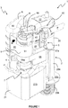
- a cistern flushing apparatus 1 including a flushing device 2 for fluid connection with an outlet of a cistern (not shown) and an integrated hydraulic circuit 3 for operating the flushing device 2 and for filling a cistern (not shown) following a flushing event.
- the flushing device 2 is in the form of an adjustable syphon 2 similar to that which is disclosed in GB2486776 . More specifically, the syphon 2 includes first, second and third parts 20, 21, 22 mounted in telescopic relation with one another to enable adjustment of the flush volume characteristics thereof.
- the first part 20 includes an evacuation tube 20a having a radial flange 20c and threaded portion 20b extending from the flange 20c for insertion through an outlet in the base of a cistern (not shown) to be secured thereto by a nut (not shown) in the normal way.
- the second part 21 includes a suction tube 21a and an open-ended chamber 21b.
- the third part 22 is in the form of an inverted generally U-shaped duct with an upleg portion 22a and a downleg portion 22b.
- the upleg portion 22a and downleg portion 22b of the U-shaped duct 22 are each mounted in telescopic relation with the suction tube 21a and evacuation tube 20a respectively.
- the first part 20 also includes a pair of lugs 20d projecting laterally from its upper end each with a hole 20e therethrough.
- the second part 21 includes a flat bracket 21d projecting laterally from the upper end of the suction tube 21a and having a plurality of spaced holes 21e through its thickness.
- the third part 22 includes a chain of lugs 22d extending downwardly from the front of the bight of the U between the downleg and upleg portions 22a, 22b and having a plurality of vertically spaced holes 22e through its thickness.
- a releasable fastener 23 (shown in Figure 4 ) including a pair of spaced pins extends through a pair of adjacent holes 20e, 21e, 22e in each of the first, second and third parts 20, 21, 22 to secure simultaneously the parts 20, 21, 22 together.
- the first part 20 includes a longitudinally extending rib 20f and the second part 21 includes a bracket 21f with a keyway that receives the rib 20f of the first part.
- a priming means in the form of a piston 23 including a frame 24 formed by a peripheral rim 24a with a series of ribs 24b extending between the sides of the rim 24a to provide a series of openings therebetween.
- the piston 23 also includes a flexible diaphragm 25 secured at the centre of piston 23 by a cylindrical rod mount 26 which receives and secures a piston rod 27.
- the piston rod 27 extends upwardly from the piston 23, through the top wall of the chamber 21b and is formed of a material having sufficient mass to urge, in use, the piston 23 back down toward its home position, as shown in Figure 5 .
- the top wall of the open ended chamber 21b also includes a series of openings 28 about the piston rod 27 and an inverted top-hat shaped sealing element 29 that surrounds the piston rod and is biased by a spring 29a against the top wall to cover and seal the openings 28.
- the rod mount 26 abuts the sealing element 29 and urges it against the spring bias to reveal the openings 28.
- a partial flush can be achieved by keeping the piston 23 in a raised condition, since the syphonic action is broken when the water level reaches the openings 28.
- the integrated hydraulic circuit 3 includes a manifold 4, a filling device 5, an accumulator 6, an operating valve 7, a hydraulic actuator 8 and a telescopic lock 9.
- the manifold 4 includes an inlet part 40, which defines a horizontal inlet passage 41 and a vertical outlet chamber 42, and an extension part 43 received telescopically within the outlet chamber 42 of the inlet part 40, which defines an adjustable extension of the vertical outlet chamber 42.
- the extension part 43 of the manifold 4 includes a pair of radial grooves 44 at its upper end that receive respective O-ring seals for sealingly engaging the outlet chamber 42.
- the extension part 43 also includes an accumulator port 45 extending laterally from a lower end thereof and having a pair of flanges 46 forming opposed facing locking channels on either side of the accumulator port 45.
- the inlet part 40 includes a coupling 10 at the inlet end of the inlet passage 41, more of which later.
- the filling device 5 includes a float-operated diaphragm-type equilibrium valve 50 in this embodiment.
- the valve 50 includes a two-part housing 51, a diaphragm 52 with a peripheral flange captivated between the two parts of the housing 51 and a flow restrictor pin extending through a hole through a central, enlarged valve member portion of the diaphragm 52.
- the housing 51 On a first side of the diaphragm 52, the housing 51 includes an inlet 53, a plurality of radial outlets 54 and a valve seat between the inlet 53 and outlets 54 against which the central portion of the diaphragm 52 seats when the valve 50 is in a closed condition.
- a control chamber defined between the diaphragm 52 and a facing portion of the housing 51 with a bleed port 55 extending from the control chamber through the housing 51.
- the valve 50 is mounted to the inlet part 40 of the manifold 4 such that the inlet 53 is coupled to and in fluid communication with the outlet chamber 42.
- the filling device 5 also includes a float chamber or reservoir 56, a float 57 and a float arm 58, all of which are mounted to the inlet part 40 of the manifold 4.
- the float chamber 56 is in the form of an open top container with a draining port (not shown) in its base and a mounting bracket 56a which surrounds the lower end of the inlet part 40 that defines the outlet chamber 42.
- the float 57 in this embodiment is an open bottom container with an upstand 57a extending upwardly from the top of the container and having a series of holes through its thickness adjacent its upper end.
- the float arm 58 includes a resilient stop 58a at a first of its ends and a hole at a second of its ends for receiving a fastener that extends therethrough and into one of the holes of the upstand 57a of the float 57.
- the float arm 58 is pivotally mounted relative to the inlet part 40 intermediate its ends such that when the float 57 is in a raised position the stop 58a of the arm 58 closes the bleed port 55 of the valve 50 and when the float 57 is in a lowered position the bleed port 55 is open.
- the accumulator 6 includes an inverted bottle 60 having a kidney shaped horizontal cross-section and a mouth 61 at its lower end that is threadedly engaged with a coupling adapter 62.
- the mouth 61 of the bottle 60 includes a radial recess about its outer surface within which is received an O-ring for providing a sealed connection between the bottle 60 and the coupling adapter 62.
- the coupling adaptor 62 defines a 90 degree elbow to provide a horizontal inlet to the accumulator 6 and includes a pair of flanges 63 on either side of the horizontal inlet to provide a bayonet fitting for receipt within the locking channels defined by the flanges 46 of the accumulator port 45.
- the accumulator 6 is mounted to the accumulator port 45 by offering up the coupling adapter 62 with the bottle 60 oriented horizontally away from the syphon 2 such that the flanges 63 are oriented vertically, between the flanges 46 of the accumulator port 45.
- the accumulator 6 is then rotated upwardly to the orientation shown in Figure 9 such that the flanges 63 are received within the locking channels defined by the flanges 46 of the accumulator port 45.
- the inlet of the accumulator 6 is lowermost such that pressurised fluid introduced therein from the source compresses air within the container to provide a pressurised store of water.
- the operating valve 7 is similar to the valve 50 of the filling device 5, but rather than being float-operated it is operated by a separate push button actuator 10 (shown in Figures 14 to 18 ).
- the valve 7 includes a two-part housing 71, a diaphragm 72 with a peripheral flange captivated between the two parts of the housing 71 and a flow restrictor pin extending through a hole through a central, enlarged valve member portion of the diaphragm 72.
- the housing 71 On a first side of the diaphragm 72, the housing 71 includes an inlet 73, a plurality of radial outlets 74 and a valve seat between the inlet 73 and outlets 74 against which the central portion of the diaphragm 72 seats when the valve 7 is in a closed condition.
- a control chamber defined between the diaphragm 72 and a facing portion of the housing 71 with a bleed port 75 extending from the control chamber through to a push fit fitting 76 in the housing 71.
- Attached to the push fit fitting 76 is a bleed pipe BP operatively connected to the push button actuator 10.
- the operating valve 7 is mounted to the extension part 43 of the manifold 4 such that the inlet 73 is coupled to and in fluid communication with the outlet chamber 42.
- the hydraulic actuator 8 shown more clearly in Figure 5 , includes an actuator cylinder 80 formed integrally with the extension part 43 of the manifold 4 and an actuator piston 81 reciprocable within the cylinder 80.
- the actuator piston 81 includes a hole within which the upper end of the piston rod 27 is received and secured by a screw 82.
- the bottom end of the actuator cylinder 80 is fed by the outlets 74 of the operating valve 7 and the top end of the actuator cylinder 80 is open.
- the actuator piston 81 is sized and dimensioned such that a fluid flow entering the actuator cylinder 80 from below forces the actuator piston 81 upwardly within the actuator cylinder 80.
- the actuator piston 81 is also sized and dimensioned such that the clearance between the actuator piston 81 and the cylinder 80 permits some fluid to flow therebetween.
- the actuator piston 81 is formed of a plastics material having a relatively low weight.
- the telescopic lock 9 includes a rack 90 (shown more clearly in Figures 5 and 9 ) and a cooperating latch 91.
- the rack 90 is secured to the outside of the actuator cylinder 80 and includes a series of teeth 92 that extend substantially horizontally to define gaps therebetween.
- the latch 91 surrounds the inlet part 40 that defines the vertical outlet chamber 42 of the manifold and is rotatably captivated between the horizontal inlet passage 41 and the mounting bracket 56a of the float chamber 56.
- the latch 91 also includes a flat handle 93 to enable its manipulation and a series of teeth 94 that extend parallel to the teeth 92 of the rack 90 for engagement with the gaps between them.
- the teeth 62, 63 lie at an angle relative to the horizontal so as to inhibit inadvertent disengagement between the latch 91 and the rack 90.
- the handle 93 of the latch 91 holds the accumulator 6 in place by inhibiting its rotation in the reverse direction to that described above.
- the handle 93 may be rotated in direction A to release the teeth 94 of the latch 91 from those of the rack 90, thereby enabling the inlet part 40 of the manifold 4 to be moved up or down with respect to the extension part 43.
- the entire filling device 5 is mounted to and moves with the inlet part 40, thereby enabling adjustment of the position of the filling device 5 relative to the bight of the U of the third part 22 of the syphon 2. It will also be appreciated that this position alters the fill volume of the cistern, since the float chamber 56 and float 57 are also moved.
- the third part 22 of the syphon 2 may be raised relative to the first and second parts 20, 21 and the inlet part 40 of the manifold may then be raised by a similar distance together with the filling device 5.
- the invention provides an integrated flushing and filling apparatus 1 that is adjustable to alter the flushing characteristics with minimal effort.
- such adjustment would require both an adjustable flushing device 2 and an adjustable filling device 5, which are not always present and, in any event, their independent adjustment would be more cumbersome.
- the inlet part 40 of the manifold 4 also includes an anti back-syphonage valve 47 in the form of a non-return air valve 47.
- the non-return valve 47 includes a valve member 48 with a dome-shaped head carrying an O-ring that is biased by a spring 49 to seat against a valve seat.
- the force of the spring 49 is configured such that a back flow of pressure toward the supply pipe P from the manifold 4 causes the valve member 48 to unseat and allow air to be introduced into the manifold, thereby preventing a flow of water from the outlet chamber 42 and extension part 43 back into the supply pipe P.
- the inlet coupling 10 includes a first part 11 with a locking ring 12 having a series of inwardly extending radial teeth 13 and a triangular handle 14 for rotating the locking ring 12 between coupled and uncoupled orientations.
- the coupling 10 also includes a second part 15 with a series of outwardly extending radial teeth 16 each having a lead-in to facilitate insertion into the first part 11.
- the first part 11 includes a stepped recess 11a downstream of the locking ring 12.
- the second part 15 includes a filter recess 17 at its leading end, a push fit fitting 18 at its trailing end and an O-ring seal 19 received in a radial groove intermediate its ends which seals the second part 15 within the first part 11.
- the push fit fitting 18 includes an O-ring seal 18a for sealing against a supply pipe P received by the push fit fitting 18, a collapsible collar 18b and a retaining ring 18c surrounding the collapsible collar 18b.
- the collapsible collar 18b and retaining ring 18c have cooperating tapered surfaces such that the collapsible collar 18b is compressed on attempted removal, thereby retaining the supply pipe P within the push fit fitting 18.
- the coupling 10 also includes a conical filter 17a having a frame 17b with a circular inlet portion 17c corresponding to the mouth of the filter 17a and an O-ring seal 17d received within a radial groove in the circular inlet portion 17c which seals against a facing surface of the filter recess 17 of the second part 15 of the coupling 10.
- the second part 15 is insertable into the first part 11 with its teeth 16 passing through the gaps between the teeth 13 of the first part 11.
- the teeth 13, 16 of the first and second parts 11, 15 are aligned and removal of the second part 15 from the first part 11 is prevented.
- the push button actuator 100 for operating the syphon 2.
- the push button actuator 100 in this embodiment includes a manifold 101, a body 102, a surround 103, a push button 104 and a hexagonal securing nut 105 with an internal thread.
- the manifold 101 includes an internally threaded hollow cylinder 110 with an open end and a closed end, a radial inlet port 111 and a radial outlet port 112.
- Each of the inlet and outlet ports 111, 112 includes a push fit fitting for releasably securing and sealingly receiving a flexible tube (not shown).
- the bleed pipe BP connected to the bleed port 75 of the operating valve 7 is configured to be connected to the inlet port 111 and a further pipe (not shown) is configured to connect to the outlet port 112 at one end and feed into the cistern (not shown) at the other end.
- the body 102 is in the form of a hollow cylinder with a central, threaded section 121, a tail section 122 of reduced diameter, also externally threaded, and a mounting flange 123 at the opposite end of the body 102 to the tail section 122.
- the tail section 122 includes radial inlet passageways 122a and radial outlet passageways 122b axially spaced from the inlet passageways 122a.
- the mounting flange 123 includes a series of radial spokes 123a separated by axial holes 123b about the mounting flange 123.
- the surround 103 is in the form of a hollow cylinder 130 with an outwardly extending radial flange 131 at one end and an inwardly extending radial flange 132 at the other end to form a base ring 132 of the surround.
- the base ring 132 includes a series of castellations 133 extending about its innermost edge.
- Each castellation 133 includes a pair of projections 134 at its outermost corners, which together define a recess 135.
- the push button 104 includes a dome-shaped head 140 and a stem 141 movably received within the body 102.
- the push button 104 is movable within the body 102 between a deployed position shown in Figures 14, 16 and 17 and an actuated or depressed position in which the stem 141 is pushed further into the body 102.
- fluid communication between the inlet passageways 122a and the outlet passageways 122b is closed in the deployed position and open in the actuated or depressed position.
- the push button 104 is also biased by a spring 142 to the deployed position.
- water is prevented from flowing from the inlet passageways 122a to the outlet passageways 122b until the push button 104 is operated.
- water On operation of the push button 104, water is able to bleed from the bleed port 75 through the push button actuator 100 and back into the cistern (not shown) through the aforementioned pipes.
- the body 102 is received within the surround 103 such that the mounting flange 123 of the body 102 engages the base ring 132 of the surround 103 and the securing nut 105 is threadedly engaged with the central section 121 of the body 102.
- the tail section 122 of the body 102 is received within and threadedly engaged with the cylinder 110 of the manifold 101 such that the inlet passageways 122a are aligned with the radial inlet port 111 and the outlet passageways 122b are aligned with the radial outlet port 102.
- the push button actuator 100 may be adapted to suit the requirements of multiple different installations.
- the arrangement of Figure 16 may be desirable for aesthetic purposes, whilst the arrangement of Figure 17 enables users with less dexterity to operate the push button actuator 100 with ease.
- the bleed port 75 of the operating valve is also blocked, thereby pressurising the control chamber defined between the diaphragm 72 and a facing portion of the housing 71 and forcing the diaphragm 72 against the valve seat to close the operating valve 7. Pressurised water then charges the accumulator 6 ready for operation.
- the head 140 of the push button actuator 100 is depressed, which opens fluid communication between the inlet 111 and the outlet 112, thereby allowing flow from the bleed port 75 of the operating valve 7 through the bleed pipe BP and through the push button actuator 100 into the cistern (not shown).
- This flow releases the pressure within the control chamber of the operating valve 7 and the pressure within the manifold 4 unseats the diaphragm 72.
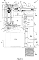
- Water then flows as illustrated in Figure 5 from both the supply pipe P and from the accumulator 6 through the outlets 74 of the operating valve 7 and into the actuator cylinder 80, thereby forcing the actuator piston 81 upwardly and forcing the syphon piston 23 upwardly within the syphon chamber 21b.
- the flushing apparatus 301 is similar to the flushing apparatus 1 described above, wherein like references depict like features that will not be described further herein.
- the flushing apparatus 301 according to this embodiment differs from the previous embodiment in that the hydraulic circuit 303 for operating the flushing device 2 is not integral with the flushing device 2 and it incorporates an air introduction assembly 310.
- the hydraulic circuit 303 includes a supply pipe P incorporating a non-return valve 330, which feeds into an inlet manifold 331 via a push fit inlet fitting 331a.
- the hydraulic circuit 303 also includes an accumulator 306, an outlet manifold 332 and an outlet pipe O connecting an outlet push fit fitting 332a of the outlet manifold 332 to a push fit fitting 307 which feeds into the operating valve 7.
- the accumulator 306 is in the form of a bottle 360 with which the inlet and outlet manifolds 331, 332 are both formed integrally at its mouth.
- the accumulator 306 includes a water inlet tube 361 fluidly connected to and extending orthogonally from the supply pipe P and push fit fitting 331a into the accumulator 306 toward its base 362.
- the water inlet tube 361 includes a necked portion 363, which accelerates, or throttles, the flow of water therethrough.
- the accumulator 306 also includes a water outlet tube 364 fluidly connected to and extending from the outlet manifold 332 into the accumulator 306 toward its base 362.
- the inlet manifold 331 includes a third branch 333 receiving the air introduction assembly 310.
- the third branch 333 includes a flange at its upper end and receives an insert 311.
- the insert 311 includes a part-spherical shoulder for redirecting the inlet water flowing from the supply pipe P into the water inlet tube 361 and an air inlet tube 312 open at its upper end and extending into the necked portion 363 of the water inlet tube 361 to provide fluid communication between the third branch 333 and the necked portion 363.
- the air introduction assembly 310 also includes a non-return valve 313, which includes an air inlet 313a, a valve member 314 reciprocable within a retainer 315.
- the valve member 314 includes a piston with an O-ring seal about its periphery and a longitudinal guide pin received within a guide ring in the base of the retainer 315 to ensure smooth reciprocating motion therein.
- the valve member 314 is retained within the retainer 315 by a shoulder at its upper end against which the piston seals when forced in its uppermost position.
- the retainer 315 is retained within the third branch 333 by a cap ring 316 which engages the flange of the third branch 333.
- the insert 311 is captivated between the retainer 315 and a shoulder of the inlet manifold 331.
- the outlet manifold 332 includes a second outlet fitting 332b, which is in the form of a threaded tail in this embodiment.
- the apparatus 301 includes a filling device 305 having a threaded collar 350 for threadedly engaging the second outlet fitting 332b to provide a fluid connection therebetween.
- the filling device 305 is in the form of a substantially conventional fill valve 351 operated by a float 352, similar to that which is disclosed in EP0961892 and offered commercially by the present applicants, but for the means by which it connects to the outlet manifold 332 of the present invention.
- the pressure within the accumulator 306 urges the valve member 314 against the shoulder of the retainer 315, thereby sealing off the non-return valve 313.
- the operating valve 7 opens and pressurised water flows from the accumulator 306 through the outlet pipe O and through the operating valve 7 to initiate the symphonic action. This occurs even in the absence of fluid pressure from the source. Following operation, the operating valve 7 closes.
- the float 352 of the filing device 305 lowers and opens the fill valve 351 and water flows from the accumulator, out of the second outlet fitting 332b and out through the filling device 305.
- the flow of water from the supply pipe P through the water inlet tube 361 creates a venturi effect within the necked portion 363, thereby reducing the pressure within the third branch 333 of the inlet manifold 331. This reduction in pressure causes the valve member 314 to unseat from the shoulder of the retainer 315 and air is entrained from the air inlet 313a and into the accumulator 306.
- the circuit 303 pressurises and the accumulator refills, ready for the next flushing action.
- the accumulator in the specific embodiments is in the form of a bottle 60, 360, it will be appreciated that the accumulator may be provided by any enclosed volume, provided by, for example, multiple components assembled together to form a reservoir that is configured to function as described.
Landscapes
- Engineering & Computer Science (AREA)
- Health & Medical Sciences (AREA)
- Life Sciences & Earth Sciences (AREA)
- Hydrology & Water Resources (AREA)
- Public Health (AREA)
- Water Supply & Treatment (AREA)
- Mechanical Engineering (AREA)
- Aviation & Aerospace Engineering (AREA)
- Sanitary Device For Flush Toilet (AREA)
Description
- This invention relates generally to a cistern flushing apparatus as defined in
claim 1. - Toilet cisterns generally include a flushing device for discharging the contents of the cistern and a filling device for refilling the cistern following a flushing cycle.
- The flushing device is normally mounted to obstruct an outlet of the cistern that feeds a toilet pan and configured to selectively allow fluid flow therethrough to flush waste out of the pan.
- The filling device is normally connected to a mains water supply or header tank for introducing replacement water into the cistern.
- The flushing device can be operated manually, for example using a mechanical actuator in the form of a lever or push button, or automatically, for example using an electromechanical actuation system.
- Manually operated flushing devices require a predetermined amount of force to unseat a valve member, or to initiate a syphonic action in the case of syphon flushing devices.
- Recent developments aimed at reducing the force required to operate flushing device actuators have utilised mains water pressure to complement or replace the initiation force required with purely mechanical solutions. The use of mains water pressure also precludes the need for an electrical power supply.
-
WO2015036767 describes a flushing syphon that incorporates an actuator piston secured to the piston rod of a syphon-initiating piston. - The actuator piston is reciprocable within a cylinder having an inlet into which mains water pressure is selectively introduced to move the piston in order to initiate syphonic action, thereby emptying the contents of the cistern.
- Mains water is supplied to the actuator cylinder and is controlled by an in-line operating valve that is operated by a pilot valve incorporated in an operator actuated push button
-
GB 2 277 750 A - It would be desirable to provide a solution that is simpler and more adaptable to domestic installations.
- The characteristics of water supply systems, including pipes, plumbing system design and cistern characteristics can vary widely between installations.
- It is therefore a non-exclusive aim of the invention to provide a cistern flushing apparatus and associated control circuit that improves the adaptability and simplicity of known installations.
- It is a further, more general non-exclusive aim of the invention to provide an improved cistern flushing apparatus and associated control circuit.
- Accordingly, the invention provides a cistern flushing apparatus comprising a flushing device for fluid connection with an outlet of a cistern and a hydraulically-driven control circuit for operating the flushing device, the control circuit comprising a water inlet for connecting the control circuit to a source of pressurised water, an accumulator fluidly connected to the water inlet, a hydraulically-driven actuator operatively connected to the flushing device for operating the flushing device and an operating valve between the actuator and the accumulator for selectively opening fluid communication therebetween, wherein the accumulator is configured to supplement, in use, a flow supplied by the source to or through the control circuit.
- Thus, variations in pressure and/or flow caused by restrictions within the installation or any fluctuations in supply, whether from the source or from usage in other parts of the installation, can be mitigated.
- This is due to the fact that pressurised fluid introduced into the accumulator from the source compresses air within the container to provide a pressurised store of water.
- The control circuit and/or accumulator may comprise a second outlet, which may be a fluid outlet.
- The second outlet may be for fluid connection with a fluidic device, e.g. a further fluidic device.
- The second outlet may bypass or be configured, in use, to bypass the operating valve.
- The apparatus, control circuit or accumulator may comprise an air inlet and/or venturi means, e.g. for introducing, in use, air into the accumulator.
- The venturi means may comprise a venturi and/or may be downstream of the inlet or fluid inlet of the apparatus, control circuit and/or upstream of the inlet or fluid inlet of the accumulator.
- The venturi means may be in fluid communication with the air inlet, e.g. for entraining air from the air inlet into the accumulator.
- The applicants have observed that, overtime, air in the accumulator may become depleted. Whilst not wishing to be bound by any theory, this is believed to be caused by one or both of the air dissolving into the water within the accumulator and/or permeating through the wall of the accumulator.
- By regularly reintroducing air into the accumulator, this phenomenon is mitigated.
- As used herein, the terms upstream and downstream refer to locations within the apparatus, circuit or accumulator relative to the direction of flow, in use, therethrough.
- The apparatus, control circuit or accumulator may comprise an air inlet passageway, passage, tube or pipe, which may extend from the air inlet and/or to or toward the venturi means.
- The apparatus, control circuit or accumulator may comprise an inlet tube, e.g. a fluid or water inlet tube, which may be in fluid communication with the inlet or fluid or water inlet. The inlet tube may comprise a restriction, constriction or reduction in internal diameter, which may provide, at least in part, the venturi means. The inlet tube may extend into a base of the accumulator.
- At least one of the outlet(s) of the apparatus, control circuit or accumulator may be in fluid communication with the or a base of the accumulator, e.g. a sump therein. In embodiments, a water outlet passageway, passage, tube or pipe is provided, which may be in fluid communication with the sump of base of the accumulator.
- The base of the accumulator may comprise an upper portion or intended upper portion of the accumulator. Preferably, the base of the accumulator comprises a lower portion or intended lower portion of the accumulator.
- In embodiments, the outlet(s) or the outlet passageway, passage, tube or pipe is or are located at and/or extend from an upper portion or intended upper portion of the accumulator.
- The accumulator outlet passageway, passage, tube or pipe may extend into a lower portion of the accumulator, for example such that pressurised air within the accumulator and/or water introduced, in use, through the inlet or inlet pipe into the accumulator forces water out of the outlet(s) or outlet pipe, e.g. and to or toward the actuator of a cistern flushing device and/or to or toward a cistern filling device.
- The apparatus, control circuit or accumulator may comprise a non-return or one-way means, e.g. valve means.
- The non-return or one-way means may be associated with the air inlet, e.g. for allowing air to enter, in use, into the control circuit and/or inhibiting water egress from the control circuit.
- The actuator may be comprised or incorporated in, e.g. integral with, the flushing device. The actuator may be configured to operate the flushing device.
- The accumulator may comprise a container and/or a mouth. In embodiments, the mouth may provide the inlet and at least one outlet. The mouth may be in an upper or lower portion of the accumulator or container.
- The accumulator or container may describe or define a space for storing a pressurised fluid, e.g. water and/or air.
- The inlet or mouth may be fluidly connected between the inlet of the control circuit and the operating valve, e.g. such that pressurised fluid introduced therein from the source compresses air within the container to provide a pressurised store of water.
- The flushing device may, but need not, comprise a syphon or any other suitable flushing device, such as a flush valve with a pivotable or retractable valve member or plug for selectively closing the outlet of a cistern. For example, the flushing device may comprise a flushing valve that is operable or configured to operate by hydraulic fluid pressure, such as the flush valve described in
GB2488382 - Where the flushing device comprises a syphon, the syphon may have an inverted generally U shaped duct with an upleg and a downleg. The syphon may comprise an open-ended chamber, which may be fluidly connected to the upleg.
- The syphon may comprise a piston movable in the chamber. The actuator, e.g. of the control circuit, may be operatively connected to the piston, e.g. for moving the piston in the chamber to initiate a syphonic flushing action.
- The syphon may comprise two, three or more parts that may be adjustable relative to one another. The syphon may comprise a part, e.g. a first part, having an evacuation tube with a lower end adapted to be mounted to the base of a cistern.
- The syphon may comprise a part, e.g. a second part, having a suction tube and an open-ended chamber, which may have a piston movable therein, e.g. by the actuator.
- The syphon may comprise a part, e.g. a third part, having an inverted generally U-shaped duct with an upleg portion and a downleg portion.
- The upleg portion and downleg portion of the U-shaped duct may each be mounted in telescopic relation with the suction tube and evacuation tube respectively.
- The apparatus may comprise a manifold, for example an inlet manifold, which will be referred to hereinafter as an inlet manifold but this term may be replaced by the term manifold.
- The inlet manifold may include the inlet and/or an accumulator port, e.g. to which the accumulator is operatively and/or fluidly connected or coupled.
- The inlet manifold may include an outlet, e.g. a first outlet, to which the operating valve may be operatively and/or fluidly connected or coupled.
- The inlet manifold may comprise a second outlet, for example to which is fluidly connected or connectable a filling device, e.g. for refilling the cistern following a flushing event.
- The inlet manifold may comprise a part, e.g. a first part, which may include the first outlet.
- The inlet manifold may comprise a part, e.g. a second part, which may include the second outlet.
- The second part may be movable relative to the first part, for example to enable the position of the fill device to be adjusted relative to the operating valve.
- The first part of the inlet manifold may mounted to, e.g. directly or indirectly, the open-ended chamber or second part of the syphon, e.g. for movement therewith.
- At least part of the filing device may be mounted to, e.g. directly or indirectly, the second part for movement therewith. One or both of the operating valve and/or the accumulator may be mounted to, e.g. directly or indirectly, the first part.
- The first and second parts may be telescopically adjustable relative to one another. The second part may be step-wise adjustable relative to the first part.
- One of the parts, e.g. the first part, may comprise a rack, which may be mounted relative thereto or incorporated therein or otherwise associated therewith.
- The other part, e.g. the second part, may comprise a latch, which may be mounted relative thereto or incorporated therein or associated therewith.
- The latch may be for releasably engaging the rack, for example at one of a plurality of positions, e.g. to provide the step-wise adjustment.
- The teeth of the rack may lie at an angle relative, e.g. to the horizontal, such as for inhibiting inadvertent disengagement between the latch and the rack.
- In embodiments, the rack is comprised in or mounted to another part of the flushing apparatus, for example one of the parts of the syphon or the actuator.
- The actuator may comprise an actuator piston, which may be movable within an actuator chamber.
- The actuator chamber may be mounted to, e.g. directly or indirectly, the open-ended chamber or second part of the syphon, e.g. for movement therewith.
- The rack may be mounted to or formed on an outer surface of the actuator chamber.
- Thus, in embodiments where both the actuator chamber and the first part of the inlet manifold are mounted to the open-ended syphon chamber or the second part of the syphon, the rack may be fixed in position relative to both.
- The accumulator may comprise a mouth, which may be mounted, coupled or secured and/or in fluid communication with the accumulator port.
- The mouth may be mounted, coupled or secured to the accumulator port by a bayonet fitting.
- The latch may be configured to inhibit disengagement of the mouth or bayonet fitting, for example when it is engaged with the rack.
- The apparatus or control circuit may comprise a filling device, e.g. a cistern filling device. The filling device may comprise a float operated valve assembly.
- The filling device may comprise one or more of a valve, an arm, which may be pivotally mounted relative to the valve, and a float, which may be attached to the arm, e.g. at or adjacent a first end of the arm.
- The filling device may be configured such that when the float is in a raised position, a portion of the arm closes the valve, and/or when the float is in a lowered position, the valve is open.
- The filling device may comprise a float chamber or reservoir, e.g. a delayed fill float chamber or reservoir, hereinafter float chamber.
- The float may be received or receivable within the float chamber.
- The float chamber may comprise an open top and/or a draining port in its base. The float may be movable within the float chamber and/or may extend through the open top thereof.
- In embodiments, the float chamber may comprise a deflector, lid or cover, for example to prevent or inhibit water from valve of the filling device from entering, in use, the float chamber.
- In such embodiments, the float chamber may comprise a side opening, which may be of variable size and/or configuration, for allowing water from within the cistern to enter the float chamber, e.g. as the water level rises to such opening.
- The valve of the filling device may comprise an equilibrium valve, for example a diaphragm-type equilibrium valve, which may include a bleed port.
- The bleed port may be closed by the arm, e.g. the or a portion of the arm, e.g. when the float is in the raised position.
- The bleed port may be unobstructed by the arm when the float is in the lowered position.
- The apparatus may comprise a coupling, e.g. for releasably coupling, in use, the inlet to the source. The coupling may include two or more parts, e.g. first and second parts, which may be releasably coupled together.
- The coupling may be upstream of the accumulator, for example to enable the control circuit to be releasably coupled to the source. The coupling may be operable or couplable manually or automatically, e.g. via a spring loaded mechanism.
- The first part of the coupling may comprise a locking ring, which may include a series of inwardly extending radial teeth.
- The second part of the coupling may comprise a series of outwardly extending radial teeth.
- The locking ring may be movable between an uncoupled or unlocked position, e.g. in which the second part is insertable into the inlet, and/or a coupled or locked position, e.g. in which removal of the second part is prevented.
- At least one of the first and second parts of the coupling may comprise a recess for receiving a filter, e.g. such that it is captivated between the first and second parts when they are coupled together.
- The first part may comprise a stepped recess, e.g. wherein the filter is configured to abut the step when the first and second parts are coupled together.
- The second part may comprise an annular recess within which an end or periphery of the filter is received.
- The apparatus may comprise a filter, e.g. received between the first and second parts of the coupling.
- The filter may comprise a conical filter, which may include a frame with a circular inlet corresponding to the mouth of the filter.
- The filter may comprise a seal, e.g. an O-ring seal, which may be received within a radial groove in the frame or between the circular inlet of the frame and a facing surface of the first and/or second parts.
- The apparatus may comprise a push button actuator, which may be operatively connected to the control circuit, e.g. for operating the flushing device.
- The push button actuator may comprise push button mounted to a body, e.g. movably or actuatably mounted to the body.
- The push button actuator may comprise a surround with a recess, within which recess the body and/or the push button may be received.
- The surround, e.g. the recess of the surround, and the body may comprise cooperating radial features.
- The radial features may cooperate such that the push button is in a first position when the body and the surround are in a first relative radial orientation and/or is in a second position when the body and the surround are in a second relative radial orientation.
- The push button may be flush or stand proud of the surround in the first position. In the second position, the push button may be retracted relative to the first position.
- The radial features of one of the surround or the recess of the surround and the body may comprise castellations. The radial features of the other may comprise spokes.
- The spokes may rest on or against the castellations, e.g. in the first relative orientation and/or between the castellations, e.g. in the second relative orientation.
- Preferably, the surround or recess of the surround comprises the castellations and the body comprises the spokes.
- At least one or each castellation may comprise a recess, e.g. within which a respective one of the spokes is received in the first relative orientation. The recess may be formed by a pair of spaced projections.
- The apparatus or control circuit or accumulator, for example the inlet manifold, may comprise one or more non-return means, e.g. one or more non-return valves, for preventing water from flowing back through the inlet toward the source.
- The non-return means may be associated with the inlet or fluid inlet, e.g. water inlet, and/or may be upstream of the accumulator. The non-return means may be configured or operable such that the pressure within the accumulator corresponds substantially to a peak pressure to which the control circuit is exposed.
- For example, by allowing pressurised fluid from the source to enter the accumulator, whilst inhibiting such fluid from flowing from the accumulator back toward the source, the non-return means enables the accumulator to store the pressurised fluid when fluid pressure from the source drops.
- In embodiments, the non-return means may comprise an anti back-syphonage valve. In embodiments, the non-return means may comprise a valve member, which may be biased or resiliently biased to seat against a valve seat.
- The biasing force may be configured such that a back flow of pressure toward the inlet, for example from the inlet manifold or accumulator, causes the valve member to unseat and/or allow air to be introduced into the inlet or inlet manifold, e.g. thereby preventing a flow of water toward the source through the inlet.
- Embodiments of the invention will now be described by way of example only with reference to the accompanying drawings in which:
-
Figure 1 is a perspective view of a flushing apparatus according to an embodiment of the invention; -
Figure 2 is a partial section view of the apparatus ofFigure 1 illustrating the flow of pressurised water through the manifold; -
Figure 3 is a partial section view of the apparatus ofFigure 1 illustrating the flow of pressurised water into and out of the accumulator; -
Figure 4 is a partial section view of the apparatus ofFigure 1 illustrating the operating valve; -
Figure 5 is a partial section view of the apparatus ofFigure 1 illustrating the flow of pressurised water into the actuator of the flushing device; -
Figure 6 is a partial section view of the apparatus ofFigure 1 illustrating the operation of the fill device; -
Figure 7 is a partial section view of apparatus ofFigure 1 illustrating the air valve for the prevention of backflow; -
Figure 8 is a perspective view of the apparatus ofFigure 1 with the accumulator removed; -
Figure 9 is a perspective view of the apparatus ofFigure 1 with part of the integrated hydraulic circuit removed; -
Figure 10 is an exploded view of the inlet coupling of the apparatus ofFigure 1 ; -
Figure 11 is a partially assembled view of the inlet coupling ofFigure 10 ; -
Figure 12 is an assembled view of the inlet coupling ofFigures 10 and 11 ; -
Figure 13 is a section view of the assembled inlet coupling offigure 12 ; -
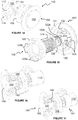
Figure 14 is a perspective view of a push button actuator for connection with the operating valve of the apparatus ofFigure 1 ; -
Figure 15 is an exploded perspective view of the body and surround of the push button actuator ofFigure 14 ; -
Figure 16 is a partial section view of the push button actuator ofFigure 14 with the push button shown in a flush position; -
Figure 17 is a partial section view similar to that ofFigure 16 in which the push button is shown in a proud position; -
Figure 18 is a perspective section view of a flushing apparatus according to another embodiment of the invention; and -
Figure 19 is a perspective section view of the accumulator of the flushing apparatus ofFigure 18 . - Referring now to
Figures 1 to 9 , there is shown acistern flushing apparatus 1 including aflushing device 2 for fluid connection with an outlet of a cistern (not shown) and an integratedhydraulic circuit 3 for operating theflushing device 2 and for filling a cistern (not shown) following a flushing event. - In this embodiment, the
flushing device 2 is in the form of anadjustable syphon 2 similar to that which is disclosed inGB2486776 syphon 2 includes first, second andthird parts first part 20 includes anevacuation tube 20a having aradial flange 20c and threadedportion 20b extending from theflange 20c for insertion through an outlet in the base of a cistern (not shown) to be secured thereto by a nut (not shown) in the normal way. Thesecond part 21 includes asuction tube 21a and an open-endedchamber 21b. Thethird part 22 is in the form of an inverted generally U-shaped duct with anupleg portion 22a and adownleg portion 22b. Theupleg portion 22a anddownleg portion 22b of theU-shaped duct 22 are each mounted in telescopic relation with thesuction tube 21a andevacuation tube 20a respectively. - The
first part 20 also includes a pair oflugs 20d projecting laterally from its upper end each with ahole 20e therethrough. Thesecond part 21 includes aflat bracket 21d projecting laterally from the upper end of thesuction tube 21a and having a plurality of spacedholes 21e through its thickness. Thethird part 22 includes a chain oflugs 22d extending downwardly from the front of the bight of the U between the downleg andupleg portions holes 22e through its thickness. A releasable fastener 23 (shown inFigure 4 ) including a pair of spaced pins extends through a pair ofadjacent holes third parts parts - The
first part 20 includes alongitudinally extending rib 20f and thesecond part 21 includes abracket 21f with a keyway that receives therib 20f of the first part. Thesefeatures parts GB2486776 - Within the open-ended
chamber 21b is a priming means in the form of apiston 23 including aframe 24 formed by aperipheral rim 24a with a series ofribs 24b extending between the sides of therim 24a to provide a series of openings therebetween. Thepiston 23 also includes aflexible diaphragm 25 secured at the centre ofpiston 23 by acylindrical rod mount 26 which receives and secures apiston rod 27. Thepiston rod 27 extends upwardly from thepiston 23, through the top wall of thechamber 21b and is formed of a material having sufficient mass to urge, in use, thepiston 23 back down toward its home position, as shown inFigure 5 . The top wall of the open endedchamber 21b also includes a series ofopenings 28 about thepiston rod 27 and an inverted top-hat shaped sealingelement 29 that surrounds the piston rod and is biased by aspring 29a against the top wall to cover and seal theopenings 28. When thepiston 23 is in a raised position, therod mount 26 abuts the sealingelement 29 and urges it against the spring bias to reveal theopenings 28. Thus, a partial flush can be achieved by keeping thepiston 23 in a raised condition, since the syphonic action is broken when the water level reaches theopenings 28. - The integrated
hydraulic circuit 3 includes amanifold 4, afilling device 5, anaccumulator 6, an operatingvalve 7, ahydraulic actuator 8 and atelescopic lock 9. Themanifold 4 includes aninlet part 40, which defines ahorizontal inlet passage 41 and avertical outlet chamber 42, and anextension part 43 received telescopically within theoutlet chamber 42 of theinlet part 40, which defines an adjustable extension of thevertical outlet chamber 42. Theextension part 43 of themanifold 4 includes a pair ofradial grooves 44 at its upper end that receive respective O-ring seals for sealingly engaging theoutlet chamber 42. Theextension part 43 also includes anaccumulator port 45 extending laterally from a lower end thereof and having a pair offlanges 46 forming opposed facing locking channels on either side of theaccumulator port 45. Theinlet part 40 includes acoupling 10 at the inlet end of theinlet passage 41, more of which later. - The filling
device 5 includes a float-operated diaphragm-type equilibrium valve 50 in this embodiment. Thevalve 50 includes a two-part housing 51, adiaphragm 52 with a peripheral flange captivated between the two parts of thehousing 51 and a flow restrictor pin extending through a hole through a central, enlarged valve member portion of thediaphragm 52. On a first side of thediaphragm 52, thehousing 51 includes aninlet 53, a plurality ofradial outlets 54 and a valve seat between theinlet 53 andoutlets 54 against which the central portion of thediaphragm 52 seats when thevalve 50 is in a closed condition. On a second side of thediaphragm 52, there is a control chamber defined between thediaphragm 52 and a facing portion of thehousing 51 with ableed port 55 extending from the control chamber through thehousing 51. Thevalve 50 is mounted to theinlet part 40 of themanifold 4 such that theinlet 53 is coupled to and in fluid communication with theoutlet chamber 42. - The filling
device 5 also includes a float chamber orreservoir 56, afloat 57 and afloat arm 58, all of which are mounted to theinlet part 40 of themanifold 4. Thefloat chamber 56 is in the form of an open top container with a draining port (not shown) in its base and a mountingbracket 56a which surrounds the lower end of theinlet part 40 that defines theoutlet chamber 42. Thefloat 57 in this embodiment is an open bottom container with anupstand 57a extending upwardly from the top of the container and having a series of holes through its thickness adjacent its upper end. Thefloat arm 58 includes aresilient stop 58a at a first of its ends and a hole at a second of its ends for receiving a fastener that extends therethrough and into one of the holes of theupstand 57a of thefloat 57. Thefloat arm 58 is pivotally mounted relative to theinlet part 40 intermediate its ends such that when thefloat 57 is in a raised position thestop 58a of thearm 58 closes thebleed port 55 of thevalve 50 and when thefloat 57 is in a lowered position thebleed port 55 is open. - The
accumulator 6 includes aninverted bottle 60 having a kidney shaped horizontal cross-section and amouth 61 at its lower end that is threadedly engaged with acoupling adapter 62. Themouth 61 of thebottle 60 includes a radial recess about its outer surface within which is received an O-ring for providing a sealed connection between thebottle 60 and thecoupling adapter 62. Thecoupling adaptor 62 defines a 90 degree elbow to provide a horizontal inlet to theaccumulator 6 and includes a pair offlanges 63 on either side of the horizontal inlet to provide a bayonet fitting for receipt within the locking channels defined by theflanges 46 of theaccumulator port 45. - Referring to
Figure 9 , theaccumulator 6 is mounted to theaccumulator port 45 by offering up thecoupling adapter 62 with thebottle 60 oriented horizontally away from thesyphon 2 such that theflanges 63 are oriented vertically, between theflanges 46 of theaccumulator port 45. Theaccumulator 6 is then rotated upwardly to the orientation shown inFigure 9 such that theflanges 63 are received within the locking channels defined by theflanges 46 of theaccumulator port 45. In this orientation, the inlet of theaccumulator 6 is lowermost such that pressurised fluid introduced therein from the source compresses air within the container to provide a pressurised store of water. - The operating
valve 7 is similar to thevalve 50 of thefilling device 5, but rather than being float-operated it is operated by a separate push button actuator 10 (shown inFigures 14 to 18 ). Thevalve 7 includes a two-part housing 71, adiaphragm 72 with a peripheral flange captivated between the two parts of thehousing 71 and a flow restrictor pin extending through a hole through a central, enlarged valve member portion of thediaphragm 72. On a first side of thediaphragm 72, thehousing 71 includes aninlet 73, a plurality ofradial outlets 74 and a valve seat between theinlet 73 andoutlets 74 against which the central portion of thediaphragm 72 seats when thevalve 7 is in a closed condition. On a second side of thediaphragm 72, there is a control chamber defined between thediaphragm 72 and a facing portion of thehousing 71 with ableed port 75 extending from the control chamber through to a pushfit fitting 76 in thehousing 71. Attached to the pushfit fitting 76 is a bleed pipe BP operatively connected to thepush button actuator 10. The operatingvalve 7 is mounted to theextension part 43 of themanifold 4 such that theinlet 73 is coupled to and in fluid communication with theoutlet chamber 42. - The
hydraulic actuator 8, shown more clearly inFigure 5 , includes anactuator cylinder 80 formed integrally with theextension part 43 of themanifold 4 and anactuator piston 81 reciprocable within thecylinder 80. Theactuator piston 81 includes a hole within which the upper end of thepiston rod 27 is received and secured by ascrew 82. The bottom end of theactuator cylinder 80 is fed by theoutlets 74 of the operatingvalve 7 and the top end of theactuator cylinder 80 is open. In this embodiment, theactuator piston 81 is sized and dimensioned such that a fluid flow entering theactuator cylinder 80 from below forces theactuator piston 81 upwardly within theactuator cylinder 80. Theactuator piston 81 is also sized and dimensioned such that the clearance between theactuator piston 81 and thecylinder 80 permits some fluid to flow therebetween. Thus, in the absence of fluid flow entering theactuator cylinder 80 from the operatingvalve 7 the mass of thepiston rod 27 urges fluid flow around theactuator piston 81 and lowering thesyphon piston 23 back to its home position. In this embodiment, theactuator piston 81 is formed of a plastics material having a relatively low weight. - The
telescopic lock 9 includes a rack 90 (shown more clearly inFigures 5 and9 ) and a cooperatinglatch 91. Therack 90 is secured to the outside of theactuator cylinder 80 and includes a series ofteeth 92 that extend substantially horizontally to define gaps therebetween. Thelatch 91 surrounds theinlet part 40 that defines thevertical outlet chamber 42 of the manifold and is rotatably captivated between thehorizontal inlet passage 41 and the mountingbracket 56a of thefloat chamber 56. Thelatch 91 also includes aflat handle 93 to enable its manipulation and a series ofteeth 94 that extend parallel to theteeth 92 of therack 90 for engagement with the gaps between them. In this embodiment, theteeth latch 91 and therack 90. - As depicted in
Figure 1 , thehandle 93 of thelatch 91 holds theaccumulator 6 in place by inhibiting its rotation in the reverse direction to that described above. Thehandle 93 may be rotated in direction A to release theteeth 94 of thelatch 91 from those of therack 90, thereby enabling theinlet part 40 of themanifold 4 to be moved up or down with respect to theextension part 43. It will be appreciated that theentire filling device 5 is mounted to and moves with theinlet part 40, thereby enabling adjustment of the position of thefilling device 5 relative to the bight of the U of thethird part 22 of thesyphon 2. It will also be appreciated that this position alters the fill volume of the cistern, since thefloat chamber 56 and float 57 are also moved. - Thus, in order to increase the flush volume of the cistern, the
third part 22 of thesyphon 2 may be raised relative to the first andsecond parts inlet part 40 of the manifold may then be raised by a similar distance together with the fillingdevice 5. - Accordingly, the invention provides an integrated flushing and filling
apparatus 1 that is adjustable to alter the flushing characteristics with minimal effort. In a conventional arrangement, such adjustment would require both anadjustable flushing device 2 and anadjustable filling device 5, which are not always present and, in any event, their independent adjustment would be more cumbersome. - As shown more clearly in
Figure 7 , theinlet part 40 of themanifold 4 also includes an anti back-syphonage valve 47 in the form of anon-return air valve 47. Thenon-return valve 47 includes avalve member 48 with a dome-shaped head carrying an O-ring that is biased by aspring 49 to seat against a valve seat. The force of thespring 49 is configured such that a back flow of pressure toward the supply pipe P from themanifold 4 causes thevalve member 48 to unseat and allow air to be introduced into the manifold, thereby preventing a flow of water from theoutlet chamber 42 andextension part 43 back into the supply pipe P. - Referring now to
Figures 10 to 13 , theinlet coupling 10 is shown in greater detail. Theinlet coupling 10 includes afirst part 11 with a lockingring 12 having a series of inwardly extendingradial teeth 13 and atriangular handle 14 for rotating the lockingring 12 between coupled and uncoupled orientations. Thecoupling 10 also includes asecond part 15 with a series of outwardly extendingradial teeth 16 each having a lead-in to facilitate insertion into thefirst part 11. Thefirst part 11 includes a steppedrecess 11a downstream of the lockingring 12. Thesecond part 15 includes afilter recess 17 at its leading end, a pushfit fitting 18 at its trailing end and an O-ring seal 19 received in a radial groove intermediate its ends which seals thesecond part 15 within thefirst part 11. - The push
fit fitting 18 includes an O-ring seal 18a for sealing against a supply pipe P received by the pushfit fitting 18, acollapsible collar 18b and a retainingring 18c surrounding thecollapsible collar 18b. Thecollapsible collar 18b and retainingring 18c have cooperating tapered surfaces such that thecollapsible collar 18b is compressed on attempted removal, thereby retaining the supply pipe P within the pushfit fitting 18. - The
coupling 10 also includes aconical filter 17a having aframe 17b with acircular inlet portion 17c corresponding to the mouth of thefilter 17a and an O-ring seal 17d received within a radial groove in thecircular inlet portion 17c which seals against a facing surface of thefilter recess 17 of thesecond part 15 of thecoupling 10. In the uncoupled orientation of the lockingring 12, thesecond part 15 is insertable into thefirst part 11 with itsteeth 16 passing through the gaps between theteeth 13 of thefirst part 11. In the coupled orientation of the locking ring, theteeth second parts second part 15 from thefirst part 11 is prevented. - Referring now to
Figures 14 to 17 , there is shown apush button actuator 100 for operating thesyphon 2. Thepush button actuator 100 in this embodiment includes a manifold 101, abody 102, asurround 103, apush button 104 and ahexagonal securing nut 105 with an internal thread. The manifold 101 includes an internally threadedhollow cylinder 110 with an open end and a closed end, aradial inlet port 111 and aradial outlet port 112. Each of the inlet andoutlet ports bleed port 75 of the operatingvalve 7 is configured to be connected to theinlet port 111 and a further pipe (not shown) is configured to connect to theoutlet port 112 at one end and feed into the cistern (not shown) at the other end. - The
body 102 is in the form of a hollow cylinder with a central, threadedsection 121, atail section 122 of reduced diameter, also externally threaded, and a mountingflange 123 at the opposite end of thebody 102 to thetail section 122. Thetail section 122 includesradial inlet passageways 122a andradial outlet passageways 122b axially spaced from theinlet passageways 122a. The mountingflange 123 includes a series ofradial spokes 123a separated byaxial holes 123b about the mountingflange 123. - The
surround 103 is in the form of ahollow cylinder 130 with an outwardly extendingradial flange 131 at one end and an inwardly extendingradial flange 132 at the other end to form abase ring 132 of the surround. Thebase ring 132 includes a series ofcastellations 133 extending about its innermost edge. Eachcastellation 133 includes a pair ofprojections 134 at its outermost corners, which together define arecess 135. - The
push button 104 includes a dome-shapedhead 140 and astem 141 movably received within thebody 102. Thepush button 104 is movable within thebody 102 between a deployed position shown inFigures 14, 16 and 17 and an actuated or depressed position in which thestem 141 is pushed further into thebody 102. In this embodiment, fluid communication between theinlet passageways 122a and theoutlet passageways 122b is closed in the deployed position and open in the actuated or depressed position. Thepush button 104 is also biased by aspring 142 to the deployed position. Thus, water is prevented from flowing from theinlet passageways 122a to theoutlet passageways 122b until thepush button 104 is operated. On operation of thepush button 104, water is able to bleed from thebleed port 75 through thepush button actuator 100 and back into the cistern (not shown) through the aforementioned pipes. - In an assembled condition, the
body 102 is received within thesurround 103 such that the mountingflange 123 of thebody 102 engages thebase ring 132 of thesurround 103 and the securingnut 105 is threadedly engaged with thecentral section 121 of thebody 102. In addition, thetail section 122 of thebody 102 is received within and threadedly engaged with thecylinder 110 of the manifold 101 such that theinlet passageways 122a are aligned with theradial inlet port 111 and theoutlet passageways 122b are aligned with theradial outlet port 102. - As illustrated in
Figure 16 , when thebody 102 is in a first orientation thecastellations 133 of thesurround 103 are received withinaxial holes 123b between theradial spokes 123a of thebody 102 and thepush button 104 is substantially flush with the outwardly extendingradial flange 131 of thesurround 103. As illustrated inFigure 17 , when the body is in a second orientation, theradial spokes 123a of thebody 102 rest on thecastellations 133 within therecesses 135 between theprojections 134 and thepush button 104 stands proud with respect to the outwardly extendingradial flange 131 of thesurround 103. - Thus, the
push button actuator 100 may be adapted to suit the requirements of multiple different installations. For example, the arrangement ofFigure 16 may be desirable for aesthetic purposes, whilst the arrangement ofFigure 17 enables users with less dexterity to operate thepush button actuator 100 with ease. - In use and as shown in
Figures 2 and3 , when the supply pipe P is connected to a source of pressurised water, such pressurised water flows through the supply pipe P, through thefilter 17a, into themanifold 4, into theinlet 53 of thefill valve 50, into theinlet 73 of the operatingvalve 7 and into theaccumulator 6. When the cistern (not shown) is full, thearm 58 of thefilling device 5 is raised, thereby blocking thebleed port 55 of thefill valve 50, pressurising the control chamber defined between thediaphragm 52 and a facing portion of thehousing 51 and forcing thediaphragm 52 against the valve seat to close thefill valve 50. With thepush button actuator 100 in the deployed position, thebleed port 75 of the operating valve is also blocked, thereby pressurising the control chamber defined between thediaphragm 72 and a facing portion of thehousing 71 and forcing thediaphragm 72 against the valve seat to close the operatingvalve 7. Pressurised water then charges theaccumulator 6 ready for operation. - In order to initiate a flush, the
head 140 of thepush button actuator 100 is depressed, which opens fluid communication between theinlet 111 and theoutlet 112, thereby allowing flow from thebleed port 75 of the operatingvalve 7 through the bleed pipe BP and through thepush button actuator 100 into the cistern (not shown). This flow releases the pressure within the control chamber of the operatingvalve 7 and the pressure within themanifold 4 unseats thediaphragm 72. Water then flows as illustrated inFigure 5 from both the supply pipe P and from theaccumulator 6 through theoutlets 74 of the operatingvalve 7 and into theactuator cylinder 80, thereby forcing theactuator piston 81 upwardly and forcing thesyphon piston 23 upwardly within thesyphon chamber 21b. This forces thediaphragm 25 against theframe 24 of thepiston 23 and raises the volume of water within thechamber 21b up and over the bight of the U of thethird part 22 of thesyphon 2 and initiating a syphonic flushing action. Water then flows through the openings in theframe 24 of thepiston 23, urging thediaphragm 25 upwardly, and continues to flow through thesyphon 2. Thus, in situations where the pressure from the water supply is reduced or fluctuates, theaccumulator 6 provides additional pressurised flow to ensure that the syphonic action is initiated effectively. - If the
head 140 of thepush button actuator 100 continues to be depressed, water continues to flow through theactuator cylinder 80 and retains the piston in a raised position. As outlined above, this also keeps the sealingelement 29 in a raised condition exposing the series ofopenings 28 such that when the water level within the cistern (not shown) drops to this point the syphonic action is broken, thereby resulting in a partial flush. If, however, thehead 140 of thepush button actuator 100 is released immediately or shortly after it is depressed initially, a full flush is effected. - As the water level within the cistern (not shown) drops, the
float chamber 56 empties through the draining port (not shown) and thefloat 57 drops within thefloat chamber 56. At this point, thearm 58 pivots and theresilient stop 58a unseats from thebleed port 55, thereby releases the pressure within the control chamber of thefloat valve 50 and unseating thediaphragm 52. Fluid flow is then opened between theinlet 53 and theoutlets 54 and water drains out of thefloat valve 50 as illustrated inFigure 6 to refill the cistern (not shown). As the water level rises above the top of thefloat chamber 56, it is refilled and thefloat 57 is once again raised to cause theresilient stop 58a to block thebleed port 55, thereby pressurising the control chamber of thefloat valve 50 and forcing thediaphragm 52 against the valve seat and closing thefloat valve 50. - Turning now to
Figures 18 and19 , there is shown aflushing apparatus 301 according to another embodiment of the invention. Theflushing apparatus 301 according to this embodiment is similar to theflushing apparatus 1 described above, wherein like references depict like features that will not be described further herein. Theflushing apparatus 301 according to this embodiment differs from the previous embodiment in that thehydraulic circuit 303 for operating theflushing device 2 is not integral with theflushing device 2 and it incorporates anair introduction assembly 310. In this embodiment, thehydraulic circuit 303 includes a supply pipe P incorporating anon-return valve 330, which feeds into aninlet manifold 331 via a push fit inlet fitting 331a. Thehydraulic circuit 303 also includes anaccumulator 306, anoutlet manifold 332 and an outlet pipe O connecting an outlet push fit fitting 332a of theoutlet manifold 332 to a pushfit fitting 307 which feeds into the operatingvalve 7. - The
accumulator 306 is in the form of abottle 360 with which the inlet and outlet manifolds 331, 332 are both formed integrally at its mouth. Theaccumulator 306 includes awater inlet tube 361 fluidly connected to and extending orthogonally from the supply pipe P and pushfit fitting 331a into theaccumulator 306 toward itsbase 362. Thewater inlet tube 361 includes anecked portion 363, which accelerates, or throttles, the flow of water therethrough. Theaccumulator 306 also includes awater outlet tube 364 fluidly connected to and extending from theoutlet manifold 332 into theaccumulator 306 toward itsbase 362. - The
inlet manifold 331 includes athird branch 333 receiving theair introduction assembly 310. Thethird branch 333 includes a flange at its upper end and receives aninsert 311. Theinsert 311 includes a part-spherical shoulder for redirecting the inlet water flowing from the supply pipe P into thewater inlet tube 361 and anair inlet tube 312 open at its upper end and extending into thenecked portion 363 of thewater inlet tube 361 to provide fluid communication between thethird branch 333 and thenecked portion 363. - The
air introduction assembly 310 also includes anon-return valve 313, which includes anair inlet 313a, avalve member 314 reciprocable within aretainer 315. Thevalve member 314 includes a piston with an O-ring seal about its periphery and a longitudinal guide pin received within a guide ring in the base of theretainer 315 to ensure smooth reciprocating motion therein. Thevalve member 314 is retained within theretainer 315 by a shoulder at its upper end against which the piston seals when forced in its uppermost position. Theretainer 315 is retained within thethird branch 333 by acap ring 316 which engages the flange of thethird branch 333. Theinsert 311 is captivated between theretainer 315 and a shoulder of theinlet manifold 331. - The
outlet manifold 332 includes a second outlet fitting 332b, which is in the form of a threaded tail in this embodiment. Theapparatus 301 includes afilling device 305 having a threadedcollar 350 for threadedly engaging the second outlet fitting 332b to provide a fluid connection therebetween. The fillingdevice 305 is in the form of a substantiallyconventional fill valve 351 operated by afloat 352, similar to that which is disclosed inEP0961892 and offered commercially by the present applicants, but for the means by which it connects to theoutlet manifold 332 of the present invention. - In use and when the operating
valve 7 and thefill valve 351 are both closed, the pressure within theaccumulator 306 urges thevalve member 314 against the shoulder of theretainer 315, thereby sealing off thenon-return valve 313. When a user initiates a flushing action as described above in relation to the first embodiment, the operatingvalve 7 opens and pressurised water flows from theaccumulator 306 through the outlet pipe O and through the operatingvalve 7 to initiate the symphonic action. This occurs even in the absence of fluid pressure from the source. Following operation, the operatingvalve 7 closes. - As the water level drops, the
float 352 of thefiling device 305 lowers and opens thefill valve 351 and water flows from the accumulator, out of the second outlet fitting 332b and out through the fillingdevice 305. The flow of water from the supply pipe P through thewater inlet tube 361 creates a venturi effect within thenecked portion 363, thereby reducing the pressure within thethird branch 333 of theinlet manifold 331. This reduction in pressure causes thevalve member 314 to unseat from the shoulder of theretainer 315 and air is entrained from theair inlet 313a and into theaccumulator 306. As outlined above, the applicants have observed that air in the accumulator may become depleted over time, but theair introduction assembly 310 regularly reintroduces air into the accumulator, thereby mitigating this phenomenon. The provision of an air inlet which introduces air through a venturi means enables this reintroduction of air to occur automatically. - As the water level rises, the
float 352 rises and closes thefill valve 351. As a result, thecircuit 303 pressurises and the accumulator refills, ready for the next flushing action. - It will be appreciated by those skilled in the art that several variations to the aforementioned embodiments are envisaged without departing from the scope of the invention as defined in the appended claims. Whilst the accumulator in the specific embodiments is in the form of a
bottle
Claims (13)
- A cistern flushing apparatus (1, 301) comprising a flushing device (2) for fluid connection with an outlet of a cistern and a hydraulically-driven control circuit (3, 303) for operating the flushing device (1, 301), the control circuit (3, 303) comprising a water inlet (P) for fluidly connecting the control circuit (3, 303) to a source of pressurised water, an accumulator (6, 306) fluidly connected to the water inlet, a hydraulically-driven actuator (8) operatively connected to the flushing device (1, 301) for operating the flushing device (1, 301) and an operating valve (7) between the actuator (8) and the accumulator (6, 306) for selectively opening fluid communication therebetween, wherein the accumulator (6, 306) is configured to supplement, in use, the flow of pressurised water supplied by the source through the control circuit (3, 303).
- Apparatus according to claim 1 comprising an air inlet (313a) for introducing, in use, air into the accumulator (6, 306).
- Apparatus according to claim 2 comprising a venturi means downstream of the water inlet (331a), the venturi means being in fluid communication with the air inlet (313a) for entraining air from the air inlet (313a) into the accumulator (306).
- Apparatus according to claim 3 comprising an air inlet tube (312) extending from the air inlet (313a) to or toward the venturi means.
- Apparatus according to claim 3 or claim 4 comprising a water inlet tube (361) in fluid communication with the water inlet (331a) of the control circuit (303) and with the accumulator (306), the water inlet tube (361) comprising a restriction (363) therein which provides, at least in part, the venturi means.
- Apparatus according to claim 5, wherein the water inlet tube (312) extends into a base (362) of the accumulator (306).
- Apparatus according to claim 6 comprising a water outlet tube (364) in fluid communication with a sump in the base (362) of the accumulator (306).
- Apparatus according to any one of claims 2 to 7 comprising a non-return valve means (330) associated with the air inlet (313a) for allowing air to enter, in use, into the control circuit (303) while inhibiting water egress therefrom.
- Apparatus according to any preceding claim, wherein the flushing device (2) comprises a syphon having an inverted generally U shaped duct with an upleg (21a, 22a) and a downleg (22b, 20), an open-ended chamber (21b) fluidly connected to the upleg (21a, 22a) and a piston (23) movable in the chamber (21b), the actuator (8) being operatively connected to the piston (23) for moving the piston (23) in the chamber (21b) to initiate a syphonic flushing action.
- Apparatus according to any one of claims 1 to 8, wherein the flushing device comprises a flush valve.
- Apparatus according to any preceding claim comprising a cistern filling device (5, 305) in fluid communication with an outlet of the accumulator (6, 306).
- Apparatus according to claim 10, wherein the accumulator (306) comprises a first outlet (332a) in fluid communication with the actuator (8) and a second outlet (332b) which bypasses the operating valve (7) and which is in fluid communication with the cistern filling device (5, 305).
- Apparatus according to claim 11 or claim 12 comprising an inlet manifold (4), the inlet manifold (4) comprising the water inlet (40), an accumulator port (45) to which the accumulator (6) is fluidly connected, a first outlet (43, 73) to which the operating valve (7) is fluidly connected and a second outlet (42) to which the filling device (5) is fluidly connected for refilling the cistern following a flushing event.
Applications Claiming Priority (2)
| Application Number | Priority Date | Filing Date | Title |
|---|---|---|---|
| GB1602014.1A GB2547011A (en) | 2016-02-04 | 2016-02-04 | Cistern flushing apparatus and control circuit therefor |
| PCT/GB2017/050267 WO2017134448A1 (en) | 2016-02-04 | 2017-02-03 | Apparatus for flushing a toilet, comprising an accumulator |
Publications (2)
| Publication Number | Publication Date |
|---|---|
| EP3411536A1 EP3411536A1 (en) | 2018-12-12 |
| EP3411536B1 true EP3411536B1 (en) | 2020-12-23 |
Family
ID=55641811
Family Applications (1)
| Application Number | Title | Priority Date | Filing Date |
|---|---|---|---|
| EP17704060.7A Active EP3411536B1 (en) | 2016-02-04 | 2017-02-03 | Apparatus for flushing a toilet, comprising an accumulator |
Country Status (4)
| Country | Link |
|---|---|
| US (1) | US10787800B2 (en) |
| EP (1) | EP3411536B1 (en) |
| GB (1) | GB2547011A (en) |
| WO (1) | WO2017134448A1 (en) |
Families Citing this family (5)
| Publication number | Priority date | Publication date | Assignee | Title |
|---|---|---|---|---|
| WO2016163959A2 (en) * | 2015-04-07 | 2016-10-13 | Pancurák František | A toilet bowl pressure flushing system with shock wave flushing |
| US10968615B2 (en) * | 2018-11-10 | 2021-04-06 | Norman Usher | Toilet flushing apparatus and system and method |
| CN110331767B (en) * | 2019-05-27 | 2024-03-08 | 厦门建霖健康家居股份有限公司 | Pressure flushing system and toilet |
| CN110409582B (en) * | 2019-08-07 | 2024-06-11 | 厦门铱科卫浴科技有限公司 | A water outlet box of a pressure flushing system and a toilet using the water outlet box |
| WO2021097737A1 (en) * | 2019-11-21 | 2021-05-27 | 厦门立业卫浴工业有限公司 | Pneumatic drive lifting device of drain valve |
Family Cites Families (10)
| Publication number | Priority date | Publication date | Assignee | Title |
|---|---|---|---|---|
| US4142262A (en) * | 1977-07-01 | 1979-03-06 | Hamilton William H | Flush toilet system |
| US5241711A (en) * | 1991-06-24 | 1993-09-07 | Badders Edwin T | Pressurized toilet flushing assembly |
| RU2101424C1 (en) * | 1993-04-08 | 1998-01-10 | Дабл Ю/Си Текнолоджи Корпорейшн | Higher-pressure flushing system of toilet |
| US5361426A (en) * | 1993-04-16 | 1994-11-08 | W/C Technology Corporation | Hydraulically controlled pressurized water closet flushing system |
| US6029287A (en) * | 1998-09-08 | 2000-02-29 | Sloan Valve Company | Power flush tank with volume reduction tube |
| WO2000050700A1 (en) * | 1999-02-22 | 2000-08-31 | Perfecteau Llp | A water efficient toilet |
| EP1461554A2 (en) * | 2000-11-20 | 2004-09-29 | Arichell Technologies, Inc. | Toilet flusher with novel valves and controls |
| US7299508B2 (en) * | 2004-01-08 | 2007-11-27 | Feiyu Li | Pressurized flush system |
| US8196231B2 (en) * | 2007-12-11 | 2012-06-12 | P & C Hennessy Holdings, Inc. | Pressurized trap water saver toilet |
| GB201316243D0 (en) * | 2013-09-12 | 2013-10-30 | Dudley Thomas Ltd | Syphon assembly and actuator therefor |
-
2016
- 2016-02-04 GB GB1602014.1A patent/GB2547011A/en not_active Withdrawn
-
2017
- 2017-02-03 US US16/072,497 patent/US10787800B2/en not_active Expired - Fee Related
- 2017-02-03 EP EP17704060.7A patent/EP3411536B1/en active Active
- 2017-02-03 WO PCT/GB2017/050267 patent/WO2017134448A1/en not_active Ceased
Non-Patent Citations (1)
| Title |
|---|
| None * |
Also Published As
| Publication number | Publication date |
|---|---|
| EP3411536A1 (en) | 2018-12-12 |
| GB2547011A (en) | 2017-08-09 |
| GB201602014D0 (en) | 2016-03-23 |
| WO2017134448A1 (en) | 2017-08-10 |
| US10787800B2 (en) | 2020-09-29 |
| US20190032316A1 (en) | 2019-01-31 |
Similar Documents
| Publication | Publication Date | Title |
|---|---|---|
| US10787800B2 (en) | Apparatus for flushing a toilet, comprising an accumulator | |
| US7010816B2 (en) | Pressure assisted dual flush operating system | |
| US4310934A (en) | Water-conserving toilet | |
| ITMI940643A1 (en) | PRESSURIZED WATER TANK CABINET DRIVE SYSTEM | |
| CN110439073B (en) | Pressure flushing system and toilet | |
| SI9520122A (en) | Discharge valve | |
| AU2006201757A1 (en) | Discharge valve for a flushing cistern | |
| RU2688043C2 (en) | Overfill protection system of tank | |
| US10100502B2 (en) | Syphon assembly and actuator therefor | |
| US7299508B2 (en) | Pressurized flush system | |
| US9499964B2 (en) | Flush water supply device, flush water tank assembly with flush water supply device, and flush toilet with flush water tank assembly | |
| US9359752B2 (en) | Toilet discharge valve assembly having moveable buoyant float therein | |
| US10352030B2 (en) | Toilet hydraulic system | |
| EP3191653B1 (en) | Valve assembly | |
| EP2765247B1 (en) | A siphonic flushing device | |
| WO2008092208A1 (en) | Toilet flushing using air under pressure for flushing and water to replenish the trap | |
| EP2468968B1 (en) | Flushing device for a toilet | |
| KR200283239Y1 (en) | System control water level | |
| AU725659B2 (en) | Flush system | |
| EP3452666B1 (en) | Actuator for flush valve | |
| AU2005234723A1 (en) | Pressure-flushing cistern for a water closet | |
| WO2016016203A1 (en) | Tank filling valve | |
| HRP20020839A2 (en) | Flush tank feed valve | |
| CZ240292A3 (en) | Flushing device | |
| ZA200801920B (en) | Standby water reservoir system |
Legal Events
| Date | Code | Title | Description |
|---|---|---|---|
| STAA | Information on the status of an ep patent application or granted ep patent |
Free format text: STATUS: UNKNOWN |
|
| STAA | Information on the status of an ep patent application or granted ep patent |
Free format text: STATUS: THE INTERNATIONAL PUBLICATION HAS BEEN MADE |
|
| PUAI | Public reference made under article 153(3) epc to a published international application that has entered the european phase |
Free format text: ORIGINAL CODE: 0009012 |
|
| STAA | Information on the status of an ep patent application or granted ep patent |
Free format text: STATUS: REQUEST FOR EXAMINATION WAS MADE |
|
| 17P | Request for examination filed |
Effective date: 20180814 |
|
| AK | Designated contracting states |
Kind code of ref document: A1 Designated state(s): AL AT BE BG CH CY CZ DE DK EE ES FI FR GB GR HR HU IE IS IT LI LT LU LV MC MK MT NL NO PL PT RO RS SE SI SK SM TR |
|
| AX | Request for extension of the european patent |
Extension state: BA ME |
|
| DAV | Request for validation of the european patent (deleted) | ||
| DAX | Request for extension of the european patent (deleted) | ||
| STAA | Information on the status of an ep patent application or granted ep patent |
Free format text: STATUS: EXAMINATION IS IN PROGRESS |
|
| 17Q | First examination report despatched |
Effective date: 20200117 |
|
| GRAP | Despatch of communication of intention to grant a patent |
Free format text: ORIGINAL CODE: EPIDOSNIGR1 |
|
| STAA | Information on the status of an ep patent application or granted ep patent |
Free format text: STATUS: GRANT OF PATENT IS INTENDED |
|
| INTG | Intention to grant announced |
Effective date: 20201006 |
|
| GRAS | Grant fee paid |
Free format text: ORIGINAL CODE: EPIDOSNIGR3 |
|
| GRAA | (expected) grant |
Free format text: ORIGINAL CODE: 0009210 |
|
| STAA | Information on the status of an ep patent application or granted ep patent |
Free format text: STATUS: THE PATENT HAS BEEN GRANTED |
|
| AK | Designated contracting states |
Kind code of ref document: B1 Designated state(s): AL AT BE BG CH CY CZ DE DK EE ES FI FR GB GR HR HU IE IS IT LI LT LU LV MC MK MT NL NO PL PT RO RS SE SI SK SM TR |
|
| REG | Reference to a national code |
Ref country code: GB Ref legal event code: FG4D |
|
| REG | Reference to a national code |
Ref country code: DE Ref legal event code: R096 Ref document number: 602017029952 Country of ref document: DE |
|
| REG | Reference to a national code |
Ref country code: AT Ref legal event code: REF Ref document number: 1347861 Country of ref document: AT Kind code of ref document: T Effective date: 20210115 |
|
| REG | Reference to a national code |
Ref country code: IE Ref legal event code: FG4D |
|
| PG25 | Lapsed in a contracting state [announced via postgrant information from national office to epo] |
Ref country code: FI Free format text: LAPSE BECAUSE OF FAILURE TO SUBMIT A TRANSLATION OF THE DESCRIPTION OR TO PAY THE FEE WITHIN THE PRESCRIBED TIME-LIMIT Effective date: 20201223 Ref country code: GR Free format text: LAPSE BECAUSE OF FAILURE TO SUBMIT A TRANSLATION OF THE DESCRIPTION OR TO PAY THE FEE WITHIN THE PRESCRIBED TIME-LIMIT Effective date: 20210324 Ref country code: RS Free format text: LAPSE BECAUSE OF FAILURE TO SUBMIT A TRANSLATION OF THE DESCRIPTION OR TO PAY THE FEE WITHIN THE PRESCRIBED TIME-LIMIT Effective date: 20201223 Ref country code: NO Free format text: LAPSE BECAUSE OF FAILURE TO SUBMIT A TRANSLATION OF THE DESCRIPTION OR TO PAY THE FEE WITHIN THE PRESCRIBED TIME-LIMIT Effective date: 20210323 |
|
| REG | Reference to a national code |
Ref country code: AT Ref legal event code: MK05 Ref document number: 1347861 Country of ref document: AT Kind code of ref document: T Effective date: 20201223 |
|
| REG | Reference to a national code |
Ref country code: NL Ref legal event code: MP Effective date: 20201223 |
|
| PG25 | Lapsed in a contracting state [announced via postgrant information from national office to epo] |
Ref country code: SE Free format text: LAPSE BECAUSE OF FAILURE TO SUBMIT A TRANSLATION OF THE DESCRIPTION OR TO PAY THE FEE WITHIN THE PRESCRIBED TIME-LIMIT Effective date: 20201223 Ref country code: BG Free format text: LAPSE BECAUSE OF FAILURE TO SUBMIT A TRANSLATION OF THE DESCRIPTION OR TO PAY THE FEE WITHIN THE PRESCRIBED TIME-LIMIT Effective date: 20210323 Ref country code: LV Free format text: LAPSE BECAUSE OF FAILURE TO SUBMIT A TRANSLATION OF THE DESCRIPTION OR TO PAY THE FEE WITHIN THE PRESCRIBED TIME-LIMIT Effective date: 20201223 |
|
| PG25 | Lapsed in a contracting state [announced via postgrant information from national office to epo] |
Ref country code: HR Free format text: LAPSE BECAUSE OF FAILURE TO SUBMIT A TRANSLATION OF THE DESCRIPTION OR TO PAY THE FEE WITHIN THE PRESCRIBED TIME-LIMIT Effective date: 20201223 Ref country code: NL Free format text: LAPSE BECAUSE OF FAILURE TO SUBMIT A TRANSLATION OF THE DESCRIPTION OR TO PAY THE FEE WITHIN THE PRESCRIBED TIME-LIMIT Effective date: 20201223 |
|
| REG | Reference to a national code |
Ref country code: LT Ref legal event code: MG9D |
|
| PG25 | Lapsed in a contracting state [announced via postgrant information from national office to epo] |
Ref country code: SM Free format text: LAPSE BECAUSE OF FAILURE TO SUBMIT A TRANSLATION OF THE DESCRIPTION OR TO PAY THE FEE WITHIN THE PRESCRIBED TIME-LIMIT Effective date: 20201223 Ref country code: CZ Free format text: LAPSE BECAUSE OF FAILURE TO SUBMIT A TRANSLATION OF THE DESCRIPTION OR TO PAY THE FEE WITHIN THE PRESCRIBED TIME-LIMIT Effective date: 20201223 Ref country code: EE Free format text: LAPSE BECAUSE OF FAILURE TO SUBMIT A TRANSLATION OF THE DESCRIPTION OR TO PAY THE FEE WITHIN THE PRESCRIBED TIME-LIMIT Effective date: 20201223 Ref country code: LT Free format text: LAPSE BECAUSE OF FAILURE TO SUBMIT A TRANSLATION OF THE DESCRIPTION OR TO PAY THE FEE WITHIN THE PRESCRIBED TIME-LIMIT Effective date: 20201223 Ref country code: PT Free format text: LAPSE BECAUSE OF FAILURE TO SUBMIT A TRANSLATION OF THE DESCRIPTION OR TO PAY THE FEE WITHIN THE PRESCRIBED TIME-LIMIT Effective date: 20210423 Ref country code: SK Free format text: LAPSE BECAUSE OF FAILURE TO SUBMIT A TRANSLATION OF THE DESCRIPTION OR TO PAY THE FEE WITHIN THE PRESCRIBED TIME-LIMIT Effective date: 20201223 Ref country code: RO Free format text: LAPSE BECAUSE OF FAILURE TO SUBMIT A TRANSLATION OF THE DESCRIPTION OR TO PAY THE FEE WITHIN THE PRESCRIBED TIME-LIMIT Effective date: 20201223 |
|
| PG25 | Lapsed in a contracting state [announced via postgrant information from national office to epo] |
Ref country code: AT Free format text: LAPSE BECAUSE OF FAILURE TO SUBMIT A TRANSLATION OF THE DESCRIPTION OR TO PAY THE FEE WITHIN THE PRESCRIBED TIME-LIMIT Effective date: 20201223 Ref country code: PL Free format text: LAPSE BECAUSE OF FAILURE TO SUBMIT A TRANSLATION OF THE DESCRIPTION OR TO PAY THE FEE WITHIN THE PRESCRIBED TIME-LIMIT Effective date: 20201223 |
|
| REG | Reference to a national code |
Ref country code: DE Ref legal event code: R097 Ref document number: 602017029952 Country of ref document: DE |
|
| PG25 | Lapsed in a contracting state [announced via postgrant information from national office to epo] |
Ref country code: MC Free format text: LAPSE BECAUSE OF FAILURE TO SUBMIT A TRANSLATION OF THE DESCRIPTION OR TO PAY THE FEE WITHIN THE PRESCRIBED TIME-LIMIT Effective date: 20201223 Ref country code: IS Free format text: LAPSE BECAUSE OF FAILURE TO SUBMIT A TRANSLATION OF THE DESCRIPTION OR TO PAY THE FEE WITHIN THE PRESCRIBED TIME-LIMIT Effective date: 20210423 |
|
| REG | Reference to a national code |
Ref country code: BE Ref legal event code: MM Effective date: 20210228 |
|
| PG25 | Lapsed in a contracting state [announced via postgrant information from national office to epo] |
Ref country code: CH Free format text: LAPSE BECAUSE OF NON-PAYMENT OF DUE FEES Effective date: 20210228 Ref country code: AL Free format text: LAPSE BECAUSE OF FAILURE TO SUBMIT A TRANSLATION OF THE DESCRIPTION OR TO PAY THE FEE WITHIN THE PRESCRIBED TIME-LIMIT Effective date: 20201223 Ref country code: IT Free format text: LAPSE BECAUSE OF FAILURE TO SUBMIT A TRANSLATION OF THE DESCRIPTION OR TO PAY THE FEE WITHIN THE PRESCRIBED TIME-LIMIT Effective date: 20201223 Ref country code: LU Free format text: LAPSE BECAUSE OF NON-PAYMENT OF DUE FEES Effective date: 20210203 Ref country code: LI Free format text: LAPSE BECAUSE OF NON-PAYMENT OF DUE FEES Effective date: 20210228 |
|
| PLBE | No opposition filed within time limit |
Free format text: ORIGINAL CODE: 0009261 |
|
| STAA | Information on the status of an ep patent application or granted ep patent |
Free format text: STATUS: NO OPPOSITION FILED WITHIN TIME LIMIT |
|
| PG25 | Lapsed in a contracting state [announced via postgrant information from national office to epo] |
Ref country code: DK Free format text: LAPSE BECAUSE OF FAILURE TO SUBMIT A TRANSLATION OF THE DESCRIPTION OR TO PAY THE FEE WITHIN THE PRESCRIBED TIME-LIMIT Effective date: 20201223 |
|
| 26N | No opposition filed |
Effective date: 20210924 |
|
| PG25 | Lapsed in a contracting state [announced via postgrant information from national office to epo] |
Ref country code: IE Free format text: LAPSE BECAUSE OF NON-PAYMENT OF DUE FEES Effective date: 20210203 Ref country code: ES Free format text: LAPSE BECAUSE OF FAILURE TO SUBMIT A TRANSLATION OF THE DESCRIPTION OR TO PAY THE FEE WITHIN THE PRESCRIBED TIME-LIMIT Effective date: 20201223 |
|
| PG25 | Lapsed in a contracting state [announced via postgrant information from national office to epo] |
Ref country code: SI Free format text: LAPSE BECAUSE OF FAILURE TO SUBMIT A TRANSLATION OF THE DESCRIPTION OR TO PAY THE FEE WITHIN THE PRESCRIBED TIME-LIMIT Effective date: 20201223 |
|
| PG25 | Lapsed in a contracting state [announced via postgrant information from national office to epo] |
Ref country code: IS Free format text: LAPSE BECAUSE OF FAILURE TO SUBMIT A TRANSLATION OF THE DESCRIPTION OR TO PAY THE FEE WITHIN THE PRESCRIBED TIME-LIMIT Effective date: 20210423 |
|
| PG25 | Lapsed in a contracting state [announced via postgrant information from national office to epo] |
Ref country code: BE Free format text: LAPSE BECAUSE OF NON-PAYMENT OF DUE FEES Effective date: 20210228 |
|
| PGFP | Annual fee paid to national office [announced via postgrant information from national office to epo] |
Ref country code: FR Payment date: 20230207 Year of fee payment: 7 |
|
| PGFP | Annual fee paid to national office [announced via postgrant information from national office to epo] |
Ref country code: DE Payment date: 20230126 Year of fee payment: 7 |
|
| P01 | Opt-out of the competence of the unified patent court (upc) registered |
Effective date: 20230523 |
|
| PG25 | Lapsed in a contracting state [announced via postgrant information from national office to epo] |
Ref country code: CY Free format text: LAPSE BECAUSE OF FAILURE TO SUBMIT A TRANSLATION OF THE DESCRIPTION OR TO PAY THE FEE WITHIN THE PRESCRIBED TIME-LIMIT Effective date: 20201223 |
|
| PG25 | Lapsed in a contracting state [announced via postgrant information from national office to epo] |
Ref country code: HU Free format text: LAPSE BECAUSE OF FAILURE TO SUBMIT A TRANSLATION OF THE DESCRIPTION OR TO PAY THE FEE WITHIN THE PRESCRIBED TIME-LIMIT; INVALID AB INITIO Effective date: 20170203 |
|
| PG25 | Lapsed in a contracting state [announced via postgrant information from national office to epo] |
Ref country code: MK Free format text: LAPSE BECAUSE OF FAILURE TO SUBMIT A TRANSLATION OF THE DESCRIPTION OR TO PAY THE FEE WITHIN THE PRESCRIBED TIME-LIMIT Effective date: 20201223 |
|
| REG | Reference to a national code |
Ref country code: DE Ref legal event code: R119 Ref document number: 602017029952 Country of ref document: DE |
|
| PG25 | Lapsed in a contracting state [announced via postgrant information from national office to epo] |
Ref country code: MT Free format text: LAPSE BECAUSE OF FAILURE TO SUBMIT A TRANSLATION OF THE DESCRIPTION OR TO PAY THE FEE WITHIN THE PRESCRIBED TIME-LIMIT Effective date: 20201223 |
|
| PG25 | Lapsed in a contracting state [announced via postgrant information from national office to epo] |
Ref country code: DE Free format text: LAPSE BECAUSE OF NON-PAYMENT OF DUE FEES Effective date: 20240903 |
|
| PGFP | Annual fee paid to national office [announced via postgrant information from national office to epo] |
Ref country code: GB Payment date: 20241218 Year of fee payment: 9 |
|
| PG25 | Lapsed in a contracting state [announced via postgrant information from national office to epo] |
Ref country code: FR Free format text: LAPSE BECAUSE OF NON-PAYMENT OF DUE FEES Effective date: 20240229 |
|
| PG25 | Lapsed in a contracting state [announced via postgrant information from national office to epo] |
Ref country code: FR Free format text: LAPSE BECAUSE OF NON-PAYMENT OF DUE FEES Effective date: 20240229 Ref country code: DE Free format text: LAPSE BECAUSE OF NON-PAYMENT OF DUE FEES Effective date: 20240903 |
|
| PG25 | Lapsed in a contracting state [announced via postgrant information from national office to epo] |
Ref country code: TR Free format text: LAPSE BECAUSE OF FAILURE TO SUBMIT A TRANSLATION OF THE DESCRIPTION OR TO PAY THE FEE WITHIN THE PRESCRIBED TIME-LIMIT Effective date: 20201223 |