EP3411314B1 - Magnetic conveyor belt module - Google Patents
Magnetic conveyor belt module Download PDFInfo
- Publication number
- EP3411314B1 EP3411314B1 EP17748049.8A EP17748049A EP3411314B1 EP 3411314 B1 EP3411314 B1 EP 3411314B1 EP 17748049 A EP17748049 A EP 17748049A EP 3411314 B1 EP3411314 B1 EP 3411314B1
- Authority
- EP
- European Patent Office
- Prior art keywords
- magnetic
- conveyor belt
- module
- insert
- cover
- Prior art date
- Legal status (The legal status is an assumption and is not a legal conclusion. Google has not performed a legal analysis and makes no representation as to the accuracy of the status listed.)
- Active
Links
Images




Classifications
-
- B—PERFORMING OPERATIONS; TRANSPORTING
- B65—CONVEYING; PACKING; STORING; HANDLING THIN OR FILAMENTARY MATERIAL
- B65G—TRANSPORT OR STORAGE DEVICES, e.g. CONVEYORS FOR LOADING OR TIPPING, SHOP CONVEYOR SYSTEMS OR PNEUMATIC TUBE CONVEYORS
- B65G17/00—Conveyors having an endless traction element, e.g. a chain, transmitting movement to a continuous or substantially-continuous load-carrying surface or to a series of individual load-carriers; Endless-chain conveyors in which the chains form the load-carrying surface
- B65G17/30—Details; Auxiliary devices
- B65G17/46—Means for holding or retaining the loads in fixed position on the load-carriers, e.g. magnetic
-
- B—PERFORMING OPERATIONS; TRANSPORTING
- B65—CONVEYING; PACKING; STORING; HANDLING THIN OR FILAMENTARY MATERIAL
- B65G—TRANSPORT OR STORAGE DEVICES, e.g. CONVEYORS FOR LOADING OR TIPPING, SHOP CONVEYOR SYSTEMS OR PNEUMATIC TUBE CONVEYORS
- B65G2207/00—Indexing codes relating to constructional details, configuration and additional features of a handling device, e.g. Conveyors
- B65G2207/12—Chain pin retainers
Definitions
- the invention relates generally to power-driven conveyors and more particularly to modular plastic conveyor belts with metal-attracting or ferro-magnetic properties.
- Conveyors are often used to transport items.
- To convey metal or magnetically attractable items, such as bakery pans, conveyors have been used that include magnetic elements to retain the magnetically-attractive items on the conveyor. Integrating the magnetic elements into the conveyor may be cumbersome.
- Modular plastic conveyor belts are widely used in various industries to convey products.
- Modular plastic conveyor belts are constructed of a series of rows of side-by-side belt modules. Hinge eyes along opposite ends of each row interleave with hinge eyes of consecutive rows. A hinge rod inserted in the interleaved hinge eyes connects the rows together at hinge joints into an endless conveyor belt loop.
- JP 2012 041145 A discloses a conveyor belt according to the preamble of claim 1.
- a magnetic conveyor belt module comprises a main body, a magnetic element and a carrier for a magnetic element coupled to the main body.
- the module allows a magnetic element to be easily and removably integrated with the module.
- a magnetic element is seated in a recess near the top surface of the module body.
- a cover covers the magnetic element.
- a retention element retains the cover and magnetic element in place.
- the conveyor belt of the present invention is defined by at least the technical features of claim 1. Further features of the present invention are listed in the dependent claims.
- a conveyor belt module integrates a magnetic element to attract conveyed articles against the conveying surface of the module.
- a conveyor belt module 10 for a conveyor belt includes a module body 12 that extends longitudinally from a first end 14 to a second end 15.
- the longitudinal direction is the direction of belt travel when such a module is built into a modular conveyor belt.
- the module body extends laterally from a first edge 16 to a second edge 17. In thickness, the module body extends from an upper surface 18, which forms the conveying surface on which conveyed articles are carried, to an opposite surface 19.
- Hinge structure shown as eyes 20, extends longitudinally outward from the first and second ends of the module body.
- the tops of the hinge eyes form a continuation of the conveying surface.
- the hinge eyes on one end of the module body are laterally offset from the hinge eyes at the other end. Gaps 26 between laterally consecutive hinge eyes are sized to receive the hinge eyes of similar modules in an adjacent row of modules in a conveyor belt.
- the modules are preferably made of thermoplastic polymers, such as polypropylene, polyethylene, acetal, or composite polymers in an injection-molding process.
- Plastic conveyor belt modules made in this way are available commercially from Intralox, L.L.C., of Harahan, La., USA.
- the modules are formed of stainless steel or another suitable material.
- a number of modules 10 are used to form a conveyor belt.
- the belt may comprise a series of rows of edge-to-edge belt modules. Modules of different lateral widths are used to construct the belt in a bricklay pattern. But wide modules extending the entire width of the belt could alternatively be used.
- the belt may comprise a combination of magnetic and non-magnetic modules.
- the rows are interconnected by hinge rods 22 extending laterally through the passageways formed by the aligned openings in the interleaved hinge eyes between adjacent rows.
- the belt conveys articles atop the conveying surfaces 18 of the modules along an upper carryway portion of the conveyor.
- the belt is trained around sprockets mounted on each end of the carryway, and returns along a returnway below the carryway.
- the magnetic module 10 includes a recess, illustrated as a slot 50, in the upper surface 10 for receiving a magnetic insert.
- the illustrative slot 50 extends from the first edge 16 to an intermediate location within the body, and is open to the side of the module.
- the illustrative slot 50 slidably receives a magnetic insert 70 housing a magnet 80.
- the recess has another shape other than a slot.
- the slot has chamfered sides 51, 52 that angle inwards and a rounded end 53.
- the insert 70 has a rounded tip 73 complementary to the rounded end 53 and chamfered or tapering sides 71, 72 to form a substantially trapezoidal cross-section.
- the insert 70 includes a recess 74 or pocket for receiving a magnetic element, illustrated as a rectangular magnetic bar 80, though the invention is not so limited.
- the upper surface of the insert 70 is flush with the upper surface of the module body 12 to form a substantially continuous surface.
- the insert 70 covers and encapsulates the magnetic bar 80.
- the module further includes a retention element for retaining the magnetic insert 70 within the module body.
- the insert interacts with a hinge rod retaining element 90 to retain the insert within the module body.
- the illustrative rod retaining element 90 comprises a movable shuttle plug, such as the shuttle plugs describe in US Patent Number 5,904,241 and US Patent Number 6,814,223 , which are incorporated herein by references, or the retaining elements US Patent Number 6,857,516 and US Patent Number 7,255,227 , the contents of which are incorporated herein by reference.
- the illustrative shuttle plug 90 is inserted in a passageway 91 in the module body and into an edge hinge element 20a for retaining a rod 22 within a hinge passageway.
- the shuttle plug includes a detent 93 that extends through an opening, shown as a channel 59, in the floor of the module body slot 50.
- the detent engages a recess, shown as a channel 78, in the insert 70 to retain the insert within the module body.
- the opening 59 and recess 78 allow the shuttle plug 90 to slide within the passageway 91 while still engaging the recess of the insert 70.
- the magnetic bar 80 is preferably centered on the module body, as shown in FIG. 5 .
- a magnetic element is sandwiched between elements in the module.
- the module 110 comprises a base member 120, a top cover 150 and a magnet 180 or magnetic element sandwiched between the top cover and base member.
- the base member has a recess 122 for receiving the top cover 150. When received in the recess 122, the top cover upper surface is flush with the upper surface of the base member 120, as shown in FIG. 9 , and encapsulates the magnet 180.
- the module includes openings 126 within the hinge elements 124 for receiving hinge elements 154 on the top cover 150.
- the base hinge elements 124 sandwich the top cover hinge elements 154.
- One or more hinge rods 160 form a retention element for retaining the top cover on the base member.
- the base member and/or the top cover may include a pocket 171 for accommodating the magnet 180.
- the pocket 171 is sized and shaped to seat the magnet 180.
- the illustrative module further includes a shuttle plug 190 for retaining the hinge rods within the hinge rod passageway.
- FIGS. 11-13 show another embodiment of a magnetic conveyor belt module 210.
- the conveyor belt module 210 integrates a magnetic element 280 into the module during a secondary molding process.
- a base member 220 formed during an initial mold includes a recess or pocket 271 for receiving a magnetic element 280.
- the recess or pocket 271 includes guide pads 272, 273 for positioning the magnetic element 280.
- a cover 250 is overmolded onto the module to encapsulate the magnetic element 280.
- the base member 220 includes two passageways 221, 222 extending down from the recess 271 for creating solid protrusions 255, 256 anchoring the overmolded cover 250 to the base member 220.
- the overmolded cover 250 preferably has a top surface that is flush with the top surface of the base member 220, as shown in FIG. 13 .
- the magnetic element 280 comprises a samarium cobalt magnet, allowing the magnet the ability to maintain the ability to attract after undergoing the high temp overmolding process.
- a cover 350 for covering a magnetic element 380 may be ultrasonically welded to a base member 320 to form a magnetic conveyor belt module 300.
- the magnetic element 380 is positioned within a recess or pocket 371 in the upper surface of the base member 320.
- the recess or pocket 371 includes a deeper recess 372 configured to receive and position the magnetic element 380.
- the cover 350 as shown in FIG. 18 , includes weld joints 352 for ultrasonically welding the cover to the base member 322 to encapsulate the magnetic element 380 within the body of the module.
- the cover also includes a recess 353 for receiving the top portion of the magnetic element 380.
- the magnetic conveyor belt module integrates the magnetic element 380 into the body while providing a substantially continuous upper conveying surface 311.
- FIGS. 19-26 show a magnetic conveyor belt module 400 according to another embodiment of the invention.
- the magnetic conveyor belt module includes a module body 412 having hinge elements 420 and a recess, shown as a slot 450, for receiving a magnetic insert 470 housing a magnet 480.
- the magnetic conveyor belt module 400 is similar to the embodiment shown in FIGS. 1-6 , with the addition of an insert retainer that engages the rod retaining element 490 when the module is fully assembled.
- the illustrative insert retainer comprises first and second protrusions 475, 476 on the bottom surface of the insert 470 for engaging recesses 462, 464 in the module body.
- the illustrative magnetic insert 470 includes a rounded tip that fits into a rounded end 453 of the slot 450.
- the module includes a shuttle plug 490 inserted in a passageway 491 in the module body and into an edge hinge element for retaining a rod 494 within a hinge passageway.
- the shuttle plug includes a detent 493 that extends through an opening or abuts a side edge 459 in the floor of the module body slot 50.
- the detent engages a recess, shown as a channel 478, in the insert 470 to retain the insert within the module body.
- the opening 459 and channel 478 allow the shuttle plug 490 to slide within the passageway 491 while still engaging the recess of the insert 470.
- the channel 478 is between the first and second protrusions 475, 476 on the insert.
- the illustrative first protrusion 475 on the insert includes a sloped front face 479 to facilitate insertion and locking of the insert 470.
- the insert 470 includes a base portion 471 and an overhanging upper portion 472.
- the base portion is inserted in the slot 450, with the upper portion 472 extending above the upper surface 401 of the module body 412.
- the base portion 471 includes sloping sides, though the invention is not so limited.
- the upper portion includes a flat top surface and tapering edges 473, 474.
- the magnetic conveyor belt module 400 can be linked with other modules to form a conveyor belt, a portion 500 of which is shown.
- a magnetic conveyor belt module 400 comprising a module body 412 and a magnetic insert 470, alternates with non-magnetic modules 510 in the conveyor belt.
- the magnetic insert 470 has a top surface 477 that is above the top surface 401 of the module body 412 and hinge elements 420.
- the top surface 511 of the adjoining non-magnetic modules 510 is flush with the top surface 401 of the module body and hinge elements 420, and therefore below the top surface 477 of the magnetic insert 470. Items placed on the conveyor belt will contact and be carried by the magnetic insert upper surface 477.
- the invention is not limited to alternating magnetic and non-magnetic modules and a conveyor belt can have any suitable pattern of modules.
- a conveyor belt 600 comprises magnetic conveyor belt modules 400 alternating with raised non-magnetic modules 610.
- the raised non-magnetic modules 610 includes a raised portion 613 that forms a top surface 611 that is flush with or slightly higher than the top surface 477 of the magnetic insert 470 of a connected magnetic module 400.
- the top surface 611 can alternatively be lower than the top surface 477 of the magnetic insert, but higher than the top surface 401 of the module body of the associated magnetic conveyor belt module.
- the raised portion 613 of the non-magnetic modules 610 assists in contacting and carrying items, which may reduce wear, improve return vibrations and prevent jams in the conveyor belt 600.
- the raised portion 613 prevents or reduces pan jams by preventing or limiting damage to the insert 470.
- the raised portion 613 may reduce or prevent contamination by ensuring that the magnet is retained in the conveyor belt. In addition, magnet exposure is reduced, preserving the most expensive component of the belt, resulting in monetary savings.
- the raised portion 613 does not extend completely across the non-magnetic module 610, and the forwardmost and rearmost portions have a lower upper surface 612, so the hinge elements 620 are approximately flush with the top surface 401 of the module body 412 of the magnetic module. The raised portion maximizes wear resistance with minimal impact on the magnetic strength of the conveyor belt.
- the optimal height difference between the top surface 611 of the non-magnetic module and the top surface 477of a magnetic module can vary depending on the application.
- the raised portion maximizes wear resistance with minimal impact on the magnetic strength
- the magnetic module is not limited to the illustrative magnetic insert, and the approach of alternating magnetic modules with non-magnetic modules, where the non-magnetic module has an upper surface that is flush with or slightly higher than a cover or other insert for housing a magnet on a connected magnetic module, can have many different embodiments.
- a cover for retaining a magnet relative to a module body can be glued or otherwise attached to the module body.
- the magnetic element can be partially or fully exposed.
- the magnetic element may be at or near the top surface of the module, or inset from the top surface.
- the invention is also not limited to the illustrative magnetic bar.
- the magnetic element can have any suitable size, shape, position and orientation.
- the module comprises magnetizable material that is added during formation of the module using injection molding.
- the magnetizable material can be magnetized within the mold to incorporate a magnetic element into the conveyor belt module.
- a cover may be molded from a magnetizable plastic, and then inserted into or overmolded onto a module body. The magnetizable plastic may then be magnetized to integrate a magnetic element to a conveyor belt module.
Landscapes
- Engineering & Computer Science (AREA)
- Mechanical Engineering (AREA)
- Belt Conveyors (AREA)
- Branching, Merging, And Special Transfer Between Conveyors (AREA)
- Attitude Control For Articles On Conveyors (AREA)
- General Induction Heating (AREA)
- Non-Mechanical Conveyors (AREA)
Description
- The invention relates generally to power-driven conveyors and more particularly to modular plastic conveyor belts with metal-attracting or ferro-magnetic properties.
- Conveyors are often used to transport items. To convey metal or magnetically attractable items, such as bakery pans, conveyors have been used that include magnetic elements to retain the magnetically-attractive items on the conveyor. Integrating the magnetic elements into the conveyor may be cumbersome.
- Modular plastic conveyor belts are widely used in various industries to convey products. Modular plastic conveyor belts are constructed of a series of rows of side-by-side belt modules. Hinge eyes along opposite ends of each row interleave with hinge eyes of consecutive rows. A hinge rod inserted in the interleaved hinge eyes connects the rows together at hinge joints into an endless conveyor belt loop.
JP 2012 041145 A claim 1. - A magnetic conveyor belt module comprises a main body, a magnetic element and a carrier for a magnetic element coupled to the main body. The module allows a magnetic element to be easily and removably integrated with the module. A magnetic element is seated in a recess near the top surface of the module body. A cover covers the magnetic element. A retention element retains the cover and magnetic element in place.
- The conveyor belt of the present invention is defined by at least the technical features of
claim 1. Further features of the present invention are listed in the dependent claims. - These features and aspects of the invention, as well as its advantages, are better understood by referring to the following description, appended claims, and accompanying drawings, in which:
-
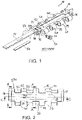
FIG. 1 is an exploded view of a magnetic conveyor belt module according to an illustrative embodiment of the invention; -
FIG. 2 is a top view of the magnetic conveyor belt module ofFIG. 1 when assembled; -
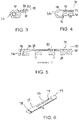
FIG. 3 is a cross-sectional view of the magnetic conveyor belt module through lines A-A ofFIG. 2 ; -
FIG. 4 is a cross-sectional view of the magnetic conveyor belt module through lines B-B ofFIG. 2 ; -
FIG. 5 is a cross-sectional view of the magnetic conveyor belt module through lines C-C ofFIG. 2 ; -
FIG. 6 is a bottom view of the magnet-carrying insert of the magnetic conveyor belt module; -
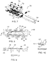
FIG. 7 is an exploded view of another embodiment of a magnetic conveyor belt module; -
FIG. 8 is a top view of the magnetic conveyor belt module ofFIG. 7 ; -
FIG. 9 is a cross-sectional view of the magnetic conveyor belt module ofFIG. 8 through lines A-A; -
FIG. 10 is a cross-sectional view of the magnetic conveyor belt module ofFIG. 8 through lines B-B; -
FIG. 11 is an isometric view of a magnetic conveyor belt module during formation according to another embodiment of the invention; -
FIG. 12 is a top view of the magnetic conveyor belt module ofFIG. 11 after overmolding of a cover for the magnetic element; -
FIG. 13 is a cross-sectional view through lines A-A inFIG. 12 ; -
FIG. 14 is an exploded, isometric view of a magnetic conveyor module according to another embodiment of the invention; -
FIG. 15 is a top view of the module ofFIG. 14 ; -
FIG. 16 is a cross-sectional view of the magnetic conveyor belt module ofFIG. 14 through lines A-A; -
FIG. 17 is a cross-sectional view of the magnetic conveyor belt module ofFIG. 14 through lines B-B; -
FIG. 18 is a bottom view of the cover of the magnetic conveyor belt module ofFIG. 14 ; -
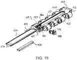
FIG. 19 is an exploded view of a magnetic conveyor belt module according to another embodiment of the invention; -
FIG. 20 is a top view of the assembled magnetic conveyor belt module ofFIG. 19 ; -
FIG. 21 is an edge view of the assembled magnetic conveyor belt module ofFIG. 19 ; -
FIG. 22 is a side view of the assembled magnetic conveyor belt ofFIG. 19 ; -
FIG. 23 is a top view of the magnet-carrying insert of the magnetic conveyor belt module ofFIG. 19 ; -
FIG. 24 is an end view of the magnet-carrying insert of the magnetic conveyor belt module ofFIG. 19 ; -
FIG. 25 is a side view of the magnet-carrying insert of the magnetic conveyor belt module ofFIG. 19 ; and -
FIG. 26 is a bottom view of the magnet-carrying insert of the magnetic conveyor belt module ofFIG. 19 . -
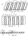
FIG. 27 is an isometric view of a portion of a conveyor belt formed by alternating magnetic conveyor belt modules and non-magnetic conveyor belt module to form the conveyor belt; -
FIG. 28 is a top view of the conveyor belt portion ofFIG. 27 ; -
FIG. 29 is a side view of the conveyor belt portion ofFIG. 27 ; -
FIG. 30 is an isometric view of a portion of a conveyor belt formed by alternating magnetic conveyor belt modules and non-magnetic conveyor belt module to form the conveyor belt according to another embodiment of the invention; -
FIG. 31 is a top view of the conveyor belt portion ofFIG. 30 ; and -
FIG. 32 is a side view of the conveyor belt portion ofFIG. 31 . - A conveyor belt module integrates a magnetic element to attract conveyed articles against the conveying surface of the module. The invention will be described below relative to certain illustrative embodiments, though those skilled in the art will recognize that the invention is not limited to the described embodiments.
- Referring to
FIGS. 1-6 , aconveyor belt module 10 for a conveyor belt includes amodule body 12 that extends longitudinally from afirst end 14 to a second end 15. The longitudinal direction is the direction of belt travel when such a module is built into a modular conveyor belt. The module body extends laterally from afirst edge 16 to a second edge 17. In thickness, the module body extends from anupper surface 18, which forms the conveying surface on which conveyed articles are carried, to anopposite surface 19. Hinge structure, shown aseyes 20, extends longitudinally outward from the first and second ends of the module body. The tops of the hinge eyes form a continuation of the conveying surface. The hinge eyes on one end of the module body are laterally offset from the hinge eyes at the other end.Gaps 26 between laterally consecutive hinge eyes are sized to receive the hinge eyes of similar modules in an adjacent row of modules in a conveyor belt. - The modules are preferably made of thermoplastic polymers, such as polypropylene, polyethylene, acetal, or composite polymers in an injection-molding process. Plastic conveyor belt modules made in this way are available commercially from Intralox, L.L.C., of Harahan, La., USA. In another embodiment, the modules are formed of stainless steel or another suitable material.
- A number of
modules 10 are used to form a conveyor belt. The belt may comprise a series of rows of edge-to-edge belt modules. Modules of different lateral widths are used to construct the belt in a bricklay pattern. But wide modules extending the entire width of the belt could alternatively be used. The belt may comprise a combination of magnetic and non-magnetic modules. The rows are interconnected byhinge rods 22 extending laterally through the passageways formed by the aligned openings in the interleaved hinge eyes between adjacent rows. The belt conveys articles atop the conveyingsurfaces 18 of the modules along an upper carryway portion of the conveyor. The belt is trained around sprockets mounted on each end of the carryway, and returns along a returnway below the carryway. - The
magnetic module 10 includes a recess, illustrated as aslot 50, in theupper surface 10 for receiving a magnetic insert. Theillustrative slot 50 extends from thefirst edge 16 to an intermediate location within the body, and is open to the side of the module. Theillustrative slot 50 slidably receives amagnetic insert 70 housing amagnet 80. In another embodiment, the recess has another shape other than a slot. - The slot has chamfered
sides insert 70 has a roundedtip 73 complementary to the rounded end 53 and chamfered or taperingsides 71, 72 to form a substantially trapezoidal cross-section. Theinsert 70 includes a recess 74 or pocket for receiving a magnetic element, illustrated as a rectangularmagnetic bar 80, though the invention is not so limited. When assembled, the upper surface of theinsert 70 is flush with the upper surface of themodule body 12 to form a substantially continuous surface. Theinsert 70 covers and encapsulates themagnetic bar 80. - The module further includes a retention element for retaining the
magnetic insert 70 within the module body. According to an illustrative embodiment of the invention, the insert interacts with a hingerod retaining element 90 to retain the insert within the module body. - The illustrative
rod retaining element 90 comprises a movable shuttle plug, such as the shuttle plugs describe inUS Patent Number 5,904,241 andUS Patent Number 6,814,223 , which are incorporated herein by references, or the retaining elementsUS Patent Number 6,857,516 andUS Patent Number 7,255,227 , the contents of which are incorporated herein by reference. - The
illustrative shuttle plug 90 is inserted in apassageway 91 in the module body and into anedge hinge element 20a for retaining arod 22 within a hinge passageway. The shuttle plug includes adetent 93 that extends through an opening, shown as a channel 59, in the floor of themodule body slot 50. The detent engages a recess, shown as achannel 78, in theinsert 70 to retain the insert within the module body. The opening 59 andrecess 78 allow theshuttle plug 90 to slide within thepassageway 91 while still engaging the recess of theinsert 70. - The
magnetic bar 80 is preferably centered on the module body, as shown inFIG. 5 . - The use of a slot, insert and automatic locking mechanism facilitates integration of an article-attracting element, such as a magnet, into the conveyor belt module.
- In another embodiment, shown in
FIG. 7-10 , a magnetic element is sandwiched between elements in the module. Themodule 110 comprises abase member 120, atop cover 150 and amagnet 180 or magnetic element sandwiched between the top cover and base member. The base member has a recess 122 for receiving thetop cover 150. When received in the recess 122, the top cover upper surface is flush with the upper surface of thebase member 120, as shown inFIG. 9 , and encapsulates themagnet 180. The module includesopenings 126 within thehinge elements 124 for receivinghinge elements 154 on thetop cover 150. The base hingeelements 124 sandwich the top cover hingeelements 154. One ormore hinge rods 160 form a retention element for retaining the top cover on the base member. The base member and/or the top cover may include apocket 171 for accommodating themagnet 180. Thepocket 171 is sized and shaped to seat themagnet 180. The illustrative module further includes ashuttle plug 190 for retaining the hinge rods within the hinge rod passageway. -
FIGS. 11-13 show another embodiment of a magneticconveyor belt module 210. Theconveyor belt module 210 integrates amagnetic element 280 into the module during a secondary molding process. Abase member 220, formed during an initial mold includes a recess orpocket 271 for receiving amagnetic element 280. The recess orpocket 271 includesguide pads magnetic element 280. After positioning themagnetic element 280 in the recess orpocket 271, acover 250 is overmolded onto the module to encapsulate themagnetic element 280. Thebase member 220 includes twopassageways recess 271 for creatingsolid protrusions overmolded cover 250 to thebase member 220. Theovermolded cover 250 preferably has a top surface that is flush with the top surface of thebase member 220, as shown inFIG. 13 . - In one embodiment, the
magnetic element 280 comprises a samarium cobalt magnet, allowing the magnet the ability to maintain the ability to attract after undergoing the high temp overmolding process. - In another embodiment of the invention, shown in
FIGS. 14-18 , acover 350 for covering amagnetic element 380 may be ultrasonically welded to abase member 320 to form a magneticconveyor belt module 300. Themagnetic element 380 is positioned within a recess or pocket 371 in the upper surface of thebase member 320. The recess or pocket 371 includes a deeper recess 372 configured to receive and position themagnetic element 380. Thecover 350, as shown inFIG. 18 , includes weld joints 352 for ultrasonically welding the cover to the base member 322 to encapsulate themagnetic element 380 within the body of the module. The cover also includes arecess 353 for receiving the top portion of themagnetic element 380. When assembled, the magnetic conveyor belt module integrates themagnetic element 380 into the body while providing a substantially continuousupper conveying surface 311. -
FIGS. 19-26 show a magneticconveyor belt module 400 according to another embodiment of the invention. The magnetic conveyor belt module includes amodule body 412 havinghinge elements 420 and a recess, shown as aslot 450, for receiving amagnetic insert 470 housing amagnet 480. The magneticconveyor belt module 400 is similar to the embodiment shown inFIGS. 1-6 , with the addition of an insert retainer that engages therod retaining element 490 when the module is fully assembled. The illustrative insert retainer comprises first andsecond protrusions insert 470 for engagingrecesses 462, 464 in the module body. - The illustrative
magnetic insert 470 includes a rounded tip that fits into arounded end 453 of theslot 450. - The module includes a
shuttle plug 490 inserted in apassageway 491 in the module body and into an edge hinge element for retaining arod 494 within a hinge passageway. The shuttle plug includes adetent 493 that extends through an opening or abuts a side edge 459 in the floor of themodule body slot 50. The detent engages a recess, shown as a channel 478, in theinsert 470 to retain the insert within the module body. The opening 459 and channel 478 allow theshuttle plug 490 to slide within thepassageway 491 while still engaging the recess of theinsert 470. The channel 478 is between the first andsecond protrusions front protrusion 479 is locked in the recess 462, the second protrusion fits in therear recess 464 and locks thedetent 493 of the shuttle plug within the passageway. - The illustrative
first protrusion 475 on the insert includes a slopedfront face 479 to facilitate insertion and locking of theinsert 470. - As shown in
FIG. 24 , theinsert 470 includes abase portion 471 and an overhangingupper portion 472. The base portion is inserted in theslot 450, with theupper portion 472 extending above theupper surface 401 of themodule body 412. Thebase portion 471 includes sloping sides, though the invention is not so limited. The upper portion includes a flat top surface and taperingedges - As shown in
FIGS. 27-29 , the magneticconveyor belt module 400 can be linked with other modules to form a conveyor belt, aportion 500 of which is shown. In the embodiment ofFIGS. 27, 28 and 29 , a magneticconveyor belt module 400, comprising amodule body 412 and amagnetic insert 470, alternates withnon-magnetic modules 510 in the conveyor belt. In the embodiment ofFIGS. 27 and 28 , themagnetic insert 470 has atop surface 477 that is above thetop surface 401 of themodule body 412 and hingeelements 420. The top surface 511 of the adjoiningnon-magnetic modules 510 is flush with thetop surface 401 of the module body and hingeelements 420, and therefore below thetop surface 477 of themagnetic insert 470. Items placed on the conveyor belt will contact and be carried by the magnetic insertupper surface 477. The invention is not limited to alternating magnetic and non-magnetic modules and a conveyor belt can have any suitable pattern of modules. - In another embodiment, shown in
FIGS. 30-32 , aconveyor belt 600 comprises magneticconveyor belt modules 400 alternating with raisednon-magnetic modules 610. In this embodiment, the raisednon-magnetic modules 610 includes a raisedportion 613 that forms a top surface 611 that is flush with or slightly higher than thetop surface 477 of themagnetic insert 470 of a connectedmagnetic module 400. The top surface 611 can alternatively be lower than thetop surface 477 of the magnetic insert, but higher than thetop surface 401 of the module body of the associated magnetic conveyor belt module. The raisedportion 613 of thenon-magnetic modules 610 assists in contacting and carrying items, which may reduce wear, improve return vibrations and prevent jams in theconveyor belt 600. The raisedportion 613 prevents or reduces pan jams by preventing or limiting damage to theinsert 470. The raisedportion 613 may reduce or prevent contamination by ensuring that the magnet is retained in the conveyor belt. In addition, magnet exposure is reduced, preserving the most expensive component of the belt, resulting in monetary savings. In the embodiment ofFIGS. 30-32 , the raisedportion 613 does not extend completely across thenon-magnetic module 610, and the forwardmost and rearmost portions have a lowerupper surface 612, so the hinge elements 620 are approximately flush with thetop surface 401 of themodule body 412 of the magnetic module. The raised portion maximizes wear resistance with minimal impact on the magnetic strength of the conveyor belt. - The optimal height difference between the top surface 611 of the non-magnetic module and the top surface 477of a magnetic module can vary depending on the application. The raised portion maximizes wear resistance with minimal impact on the magnetic strength
- The magnetic module is not limited to the illustrative magnetic insert, and the approach of alternating magnetic modules with non-magnetic modules, where the non-magnetic module has an upper surface that is flush with or slightly higher than a cover or other insert for housing a magnet on a connected magnetic module, can have many different embodiments.
- In another embodiment a cover for retaining a magnet relative to a module body can be glued or otherwise attached to the module body.
- Though the illustrative embodiments show the magnet as covered, the invention is not so limited. For example, the magnetic element can be partially or fully exposed. The magnetic element may be at or near the top surface of the module, or inset from the top surface.
- The invention is also not limited to the illustrative magnetic bar. The magnetic element can have any suitable size, shape, position and orientation.
- In another embodiment of the invention, the module comprises magnetizable material that is added during formation of the module using injection molding. The magnetizable material can be magnetized within the mold to incorporate a magnetic element into the conveyor belt module. In one embodiment, a cover may be molded from a magnetizable plastic, and then inserted into or overmolded onto a module body. The magnetizable plastic may then be magnetized to integrate a magnetic element to a conveyor belt module.
- Although the invention has been described in detail with reference to a few exemplary versions, other versions are possible. The scope of the claims is not meant to be limited to the versions described in detail.
Claims (6)
- A conveyor belt (600), comprising:a magnetic conveyor belt module (400) comprisinga module body (412) extending in thickness from a first upper surface (401) to a bottom surface, laterally from a first edge to a second edge, and longitudinally from a first end to a second end;a magnetic insert (470) coupled to the module body (412), anda non-magnetic conveyor belt module (610) connected to the magnetic conveyor belt module (400), characterized by the magnetic insert (470) having a second upper surface (477) that is above the first upper surface (401) of the module body (412) and by the non-magnetic conveyor belt module (610) having a third upper surface (611) that is non-magnetic and higher than the first upper surface (401) and wherein the third upper surface (611) is higher than the second upper surface (477).
- The conveyor belt of claim 1, further comprising a plurality of hinge elements (420) for hingedly connecting the magnetic conveyor belt module (400) to the non-magnetic conveyor belt module (610).
- The conveyor belt of claim 2, further comprising a rod retention element (490) for retaining a hinge rod (494) within a passageway formed by alternating hinge elements (420).
- The conveyor belt of claim 3, wherein the magnetic insert (470) comprises a cover housing a magnetic element (480), the cover engaging the rod retention element (490) to retain the cover on the module body of the magnetic conveyor belt module (400).
- The conveyor belt of claim 3, wherein the rod retention element (490) includes a protrusion and the cover includes a recess for engaging the protrusion.
- The conveyor belt of any one of claim 1, wherein the module body of the magnetic conveyor belt module (400) includes a slot (450) formed in the first upper surface and extending from the first edge towards the second edge and the magnetic insert (470) comprises a magnetic element (480) and a cover inserted in the slot (450), sandwiching the magnetic element between the module body and the cover, the top of the cover forming the second upper surface (477).
Applications Claiming Priority (2)
| Application Number | Priority Date | Filing Date | Title |
|---|---|---|---|
| US201662289421P | 2016-02-01 | 2016-02-01 | |
| PCT/US2017/015970 WO2017136402A1 (en) | 2016-02-01 | 2017-02-01 | Magnetic conveyor belt module |
Publications (3)
| Publication Number | Publication Date |
|---|---|
| EP3411314A1 EP3411314A1 (en) | 2018-12-12 |
| EP3411314A4 EP3411314A4 (en) | 2019-10-02 |
| EP3411314B1 true EP3411314B1 (en) | 2022-07-27 |
Family
ID=59500900
Family Applications (1)
| Application Number | Title | Priority Date | Filing Date |
|---|---|---|---|
| EP17748049.8A Active EP3411314B1 (en) | 2016-02-01 | 2017-02-01 | Magnetic conveyor belt module |
Country Status (9)
| Country | Link |
|---|---|
| EP (1) | EP3411314B1 (en) |
| JP (1) | JP6684357B2 (en) |
| CN (1) | CN108883877B (en) |
| AU (1) | AU2017214401B2 (en) |
| BR (1) | BR112018015108B1 (en) |
| DK (1) | DK3411314T3 (en) |
| ES (1) | ES2924801T3 (en) |
| MX (1) | MX2018009307A (en) |
| WO (1) | WO2017136402A1 (en) |
Cited By (1)
| Publication number | Priority date | Publication date | Assignee | Title |
|---|---|---|---|---|
| WO2026027783A3 (en) * | 2024-08-02 | 2026-04-23 | BDRS Limited | Protecting magnetically compatible surfaces |
Families Citing this family (3)
| Publication number | Priority date | Publication date | Assignee | Title |
|---|---|---|---|---|
| JP2024514862A (en) * | 2021-04-21 | 2024-04-03 | レイトラム,エル.エル.シー. | Module with conveyor belt and sliding body |
| CN113104486A (en) * | 2021-05-12 | 2021-07-13 | 苏州奇端智能科技有限公司 | Intelligent consignment machine suitable for large-scale component and consignment method thereof |
| CN116588588B (en) * | 2023-06-13 | 2026-02-10 | 常州长盈精密技术有限公司 | A magnetic transmission belt |
Family Cites Families (26)
| Publication number | Priority date | Publication date | Assignee | Title |
|---|---|---|---|---|
| US4197934A (en) * | 1976-04-28 | 1980-04-15 | The Furukawa Electric Co., Ltd. | Belt conveyor transportation system utilizing magnetic attraction |
| JPS54113172A (en) * | 1978-02-24 | 1979-09-04 | Furukawa Electric Co Ltd:The | Magnetic belt |
| JPS55155713U (en) * | 1979-04-21 | 1980-11-10 | ||
| US4586601A (en) * | 1980-09-26 | 1986-05-06 | Rexnord Inc. | Magnetized conveyor and chain links |
| US5217110A (en) * | 1992-04-23 | 1993-06-08 | Cambridge Wire Cloth Company | Modular plastic turn belt conveyor system, module, belt and drive therefor |
| CN2529844Y (en) * | 2002-04-16 | 2003-01-08 | 中冶集团北京冶金设备研究设计总院 | Lining board for transporting and storing ferromagnetic material in iron ore, sintered iron ore |
| JP4027168B2 (en) * | 2002-07-03 | 2007-12-26 | 日清紡績株式会社 | Work fixing device |
| DE10253097A1 (en) * | 2002-11-13 | 2004-06-03 | Windmöller & Hölscher Kg | conveyor system |
| KR100463447B1 (en) * | 2004-03-30 | 2004-12-24 | 최종민 | A sectional conveyer belt for crushed construction waste |
| DE102005054481A1 (en) * | 2005-11-16 | 2007-05-24 | Phoenix Conveyor Belt Systems Gmbh | Conveyor belt with exchangeable segments |
| US20090308716A1 (en) * | 2008-06-11 | 2009-12-17 | System Plast S.P.A. | Belt Conveyor |
| JP5058311B2 (en) * | 2010-08-19 | 2012-10-24 | 株式会社椿本チエイン | Conveyor chain |
| JP2013544219A (en) * | 2010-11-22 | 2013-12-12 | レイトラム,エル.エル.シー. | Conveyor belt and method for acquiring energy |
| JP2012166884A (en) * | 2011-02-14 | 2012-09-06 | Nippon Donetsuki Seisakusho:Kk | Plastic chain conveyor |
| US8881890B2 (en) * | 2011-05-23 | 2014-11-11 | Laitram, L.L.C. | Conveyor belt module with fixed axles |
| KR101103427B1 (en) * | 2011-05-30 | 2012-01-09 | 최소라 | Magnetic conveyor |
| ITMI20111582A1 (en) * | 2011-09-02 | 2013-03-03 | Rexnord Marbett Srl | ROLLER ROLLER CHAIN FOR ARTICLES CONVEYOR |
| DE102011118977A1 (en) * | 2011-11-19 | 2013-05-23 | Robert Bosch Gmbh | conveyor |
| CN105593144B (en) * | 2013-09-30 | 2018-07-27 | 莱特拉姆有限责任公司 | Magnetic Conveyor Belt module |
| TWI472767B (en) * | 2014-01-22 | 2015-02-11 | Utechzone Co Ltd | Detection device |
| CN104176509A (en) * | 2014-07-04 | 2014-12-03 | 京东方科技集团股份有限公司 | Base plate conveying device |
| CN104401648B (en) * | 2014-10-27 | 2016-04-27 | 嘉兴职业技术学院 | Feedway in a kind of singlechip chip course of processing |
| CN204489792U (en) * | 2014-11-26 | 2015-07-22 | 武汉钢铁(集团)公司 | A kind of magnetic belt conveying arrangement |
| DE102014118438B4 (en) * | 2014-12-11 | 2016-06-23 | Forbo Siegling Gmbh | Conveyor belt consisting of several modules and securing element for tool-free cutting of a coupling rod of the conveyor belt |
| CN204916909U (en) * | 2015-07-28 | 2015-12-30 | 郑国灿 | Take conveyer belt of magnet |
| CN204847102U (en) * | 2015-08-13 | 2015-12-09 | 常州市尼尔司机械有限公司 | Clamping type conveyor belt |
-
2017
- 2017-02-01 BR BR112018015108-4A patent/BR112018015108B1/en active IP Right Grant
- 2017-02-01 MX MX2018009307A patent/MX2018009307A/en unknown
- 2017-02-01 WO PCT/US2017/015970 patent/WO2017136402A1/en not_active Ceased
- 2017-02-01 ES ES17748049T patent/ES2924801T3/en active Active
- 2017-02-01 EP EP17748049.8A patent/EP3411314B1/en active Active
- 2017-02-01 AU AU2017214401A patent/AU2017214401B2/en active Active
- 2017-02-01 DK DK17748049.8T patent/DK3411314T3/en active
- 2017-02-01 JP JP2018538700A patent/JP6684357B2/en active Active
- 2017-02-01 CN CN201780007208.8A patent/CN108883877B/en active Active
Cited By (1)
| Publication number | Priority date | Publication date | Assignee | Title |
|---|---|---|---|---|
| WO2026027783A3 (en) * | 2024-08-02 | 2026-04-23 | BDRS Limited | Protecting magnetically compatible surfaces |
Also Published As
| Publication number | Publication date |
|---|---|
| AU2017214401A1 (en) | 2018-07-12 |
| JP2019503317A (en) | 2019-02-07 |
| ES2924801T3 (en) | 2022-10-11 |
| EP3411314A4 (en) | 2019-10-02 |
| BR112018015108B1 (en) | 2022-12-06 |
| CN108883877A (en) | 2018-11-23 |
| JP6684357B2 (en) | 2020-04-22 |
| WO2017136402A1 (en) | 2017-08-10 |
| MX2018009307A (en) | 2018-11-09 |
| AU2017214401B2 (en) | 2021-11-25 |
| EP3411314A1 (en) | 2018-12-12 |
| BR112018015108A2 (en) | 2018-12-11 |
| DK3411314T3 (en) | 2022-09-05 |
| CN108883877B (en) | 2021-10-15 |
Similar Documents
| Publication | Publication Date | Title |
|---|---|---|
| EP3027539B1 (en) | Magnetic conveyor belt module | |
| US10138065B2 (en) | Magnetic conveyor belt module | |
| AU2017214401B2 (en) | Magnetic conveyor belt module | |
| US8939279B2 (en) | Modular conveying systems and methods | |
| EP2714555B1 (en) | Conveyor belt module with fixed axles | |
| EP2671823A1 (en) | Chain conveyor with magnets | |
| AU2017246658B2 (en) | Magnetic conveyor belt module | |
| CA2566004C (en) | Module for a conveyor mat and modular conveyor mat | |
| WO2018144503A1 (en) | Magnetic conveyor belt module | |
| EP3959159B1 (en) | Conveyor belt and module with wear pads | |
| US20060191774A1 (en) | Chain modular and modular chain conveyor | |
| JPH11255326A (en) | Pushing body for sorting device |
Legal Events
| Date | Code | Title | Description |
|---|---|---|---|
| STAA | Information on the status of an ep patent application or granted ep patent |
Free format text: STATUS: THE INTERNATIONAL PUBLICATION HAS BEEN MADE |
|
| PUAI | Public reference made under article 153(3) epc to a published international application that has entered the european phase |
Free format text: ORIGINAL CODE: 0009012 |
|
| STAA | Information on the status of an ep patent application or granted ep patent |
Free format text: STATUS: REQUEST FOR EXAMINATION WAS MADE |
|
| 17P | Request for examination filed |
Effective date: 20180622 |
|
| AK | Designated contracting states |
Kind code of ref document: A1 Designated state(s): AL AT BE BG CH CY CZ DE DK EE ES FI FR GB GR HR HU IE IS IT LI LT LU LV MC MK MT NL NO PL PT RO RS SE SI SK SM TR |
|
| AX | Request for extension of the european patent |
Extension state: BA ME |
|
| DAV | Request for validation of the european patent (deleted) | ||
| DAX | Request for extension of the european patent (deleted) | ||
| A4 | Supplementary search report drawn up and despatched |
Effective date: 20190830 |
|
| RIC1 | Information provided on ipc code assigned before grant |
Ipc: B65G 15/58 20060101AFI20190826BHEP Ipc: B65G 17/46 20060101ALI20190826BHEP |
|
| STAA | Information on the status of an ep patent application or granted ep patent |
Free format text: STATUS: EXAMINATION IS IN PROGRESS |
|
| 17Q | First examination report despatched |
Effective date: 20211206 |
|
| GRAP | Despatch of communication of intention to grant a patent |
Free format text: ORIGINAL CODE: EPIDOSNIGR1 |
|
| STAA | Information on the status of an ep patent application or granted ep patent |
Free format text: STATUS: GRANT OF PATENT IS INTENDED |
|
| INTG | Intention to grant announced |
Effective date: 20220301 |
|
| GRAS | Grant fee paid |
Free format text: ORIGINAL CODE: EPIDOSNIGR3 |
|
| GRAA | (expected) grant |
Free format text: ORIGINAL CODE: 0009210 |
|
| STAA | Information on the status of an ep patent application or granted ep patent |
Free format text: STATUS: THE PATENT HAS BEEN GRANTED |
|
| AK | Designated contracting states |
Kind code of ref document: B1 Designated state(s): AL AT BE BG CH CY CZ DE DK EE ES FI FR GB GR HR HU IE IS IT LI LT LU LV MC MK MT NL NO PL PT RO RS SE SI SK SM TR |
|
| REG | Reference to a national code |
Ref country code: CH Ref legal event code: EP |
|
| REG | Reference to a national code |
Ref country code: AT Ref legal event code: REF Ref document number: 1506940 Country of ref document: AT Kind code of ref document: T Effective date: 20220815 |
|
| REG | Reference to a national code |
Ref country code: DE Ref legal event code: R096 Ref document number: 602017059890 Country of ref document: DE |
|
| REG | Reference to a national code |
Ref country code: IE Ref legal event code: FG4D |
|
| REG | Reference to a national code |
Ref country code: DK Ref legal event code: T3 Effective date: 20220902 |
|
| REG | Reference to a national code |
Ref country code: ES Ref legal event code: FG2A Ref document number: 2924801 Country of ref document: ES Kind code of ref document: T3 Effective date: 20221011 |
|
| REG | Reference to a national code |
Ref country code: NL Ref legal event code: FP |
|
| REG | Reference to a national code |
Ref country code: LT Ref legal event code: MG9D |
|
| PG25 | Lapsed in a contracting state [announced via postgrant information from national office to epo] |
Ref country code: SE Free format text: LAPSE BECAUSE OF FAILURE TO SUBMIT A TRANSLATION OF THE DESCRIPTION OR TO PAY THE FEE WITHIN THE PRESCRIBED TIME-LIMIT Effective date: 20220727 Ref country code: RS Free format text: LAPSE BECAUSE OF FAILURE TO SUBMIT A TRANSLATION OF THE DESCRIPTION OR TO PAY THE FEE WITHIN THE PRESCRIBED TIME-LIMIT Effective date: 20220727 Ref country code: PT Free format text: LAPSE BECAUSE OF FAILURE TO SUBMIT A TRANSLATION OF THE DESCRIPTION OR TO PAY THE FEE WITHIN THE PRESCRIBED TIME-LIMIT Effective date: 20221128 Ref country code: NO Free format text: LAPSE BECAUSE OF FAILURE TO SUBMIT A TRANSLATION OF THE DESCRIPTION OR TO PAY THE FEE WITHIN THE PRESCRIBED TIME-LIMIT Effective date: 20221027 Ref country code: LV Free format text: LAPSE BECAUSE OF FAILURE TO SUBMIT A TRANSLATION OF THE DESCRIPTION OR TO PAY THE FEE WITHIN THE PRESCRIBED TIME-LIMIT Effective date: 20220727 Ref country code: LT Free format text: LAPSE BECAUSE OF FAILURE TO SUBMIT A TRANSLATION OF THE DESCRIPTION OR TO PAY THE FEE WITHIN THE PRESCRIBED TIME-LIMIT Effective date: 20220727 Ref country code: FI Free format text: LAPSE BECAUSE OF FAILURE TO SUBMIT A TRANSLATION OF THE DESCRIPTION OR TO PAY THE FEE WITHIN THE PRESCRIBED TIME-LIMIT Effective date: 20220727 |
|
| REG | Reference to a national code |
Ref country code: AT Ref legal event code: MK05 Ref document number: 1506940 Country of ref document: AT Kind code of ref document: T Effective date: 20220727 |
|
| PG25 | Lapsed in a contracting state [announced via postgrant information from national office to epo] |
Ref country code: PL Free format text: LAPSE BECAUSE OF FAILURE TO SUBMIT A TRANSLATION OF THE DESCRIPTION OR TO PAY THE FEE WITHIN THE PRESCRIBED TIME-LIMIT Effective date: 20220727 Ref country code: IS Free format text: LAPSE BECAUSE OF FAILURE TO SUBMIT A TRANSLATION OF THE DESCRIPTION OR TO PAY THE FEE WITHIN THE PRESCRIBED TIME-LIMIT Effective date: 20221127 Ref country code: HR Free format text: LAPSE BECAUSE OF FAILURE TO SUBMIT A TRANSLATION OF THE DESCRIPTION OR TO PAY THE FEE WITHIN THE PRESCRIBED TIME-LIMIT Effective date: 20220727 Ref country code: GR Free format text: LAPSE BECAUSE OF FAILURE TO SUBMIT A TRANSLATION OF THE DESCRIPTION OR TO PAY THE FEE WITHIN THE PRESCRIBED TIME-LIMIT Effective date: 20221028 |
|
| PG25 | Lapsed in a contracting state [announced via postgrant information from national office to epo] |
Ref country code: SM Free format text: LAPSE BECAUSE OF FAILURE TO SUBMIT A TRANSLATION OF THE DESCRIPTION OR TO PAY THE FEE WITHIN THE PRESCRIBED TIME-LIMIT Effective date: 20220727 Ref country code: RO Free format text: LAPSE BECAUSE OF FAILURE TO SUBMIT A TRANSLATION OF THE DESCRIPTION OR TO PAY THE FEE WITHIN THE PRESCRIBED TIME-LIMIT Effective date: 20220727 Ref country code: CZ Free format text: LAPSE BECAUSE OF FAILURE TO SUBMIT A TRANSLATION OF THE DESCRIPTION OR TO PAY THE FEE WITHIN THE PRESCRIBED TIME-LIMIT Effective date: 20220727 Ref country code: AT Free format text: LAPSE BECAUSE OF FAILURE TO SUBMIT A TRANSLATION OF THE DESCRIPTION OR TO PAY THE FEE WITHIN THE PRESCRIBED TIME-LIMIT Effective date: 20220727 |
|
| REG | Reference to a national code |
Ref country code: DE Ref legal event code: R097 Ref document number: 602017059890 Country of ref document: DE |
|
| PG25 | Lapsed in a contracting state [announced via postgrant information from national office to epo] |
Ref country code: SK Free format text: LAPSE BECAUSE OF FAILURE TO SUBMIT A TRANSLATION OF THE DESCRIPTION OR TO PAY THE FEE WITHIN THE PRESCRIBED TIME-LIMIT Effective date: 20220727 Ref country code: EE Free format text: LAPSE BECAUSE OF FAILURE TO SUBMIT A TRANSLATION OF THE DESCRIPTION OR TO PAY THE FEE WITHIN THE PRESCRIBED TIME-LIMIT Effective date: 20220727 |
|
| PLBE | No opposition filed within time limit |
Free format text: ORIGINAL CODE: 0009261 |
|
| STAA | Information on the status of an ep patent application or granted ep patent |
Free format text: STATUS: NO OPPOSITION FILED WITHIN TIME LIMIT |
|
| PG25 | Lapsed in a contracting state [announced via postgrant information from national office to epo] |
Ref country code: AL Free format text: LAPSE BECAUSE OF FAILURE TO SUBMIT A TRANSLATION OF THE DESCRIPTION OR TO PAY THE FEE WITHIN THE PRESCRIBED TIME-LIMIT Effective date: 20220727 |
|
| 26N | No opposition filed |
Effective date: 20230502 |
|
| P01 | Opt-out of the competence of the unified patent court (upc) registered |
Effective date: 20230613 |
|
| PG25 | Lapsed in a contracting state [announced via postgrant information from national office to epo] |
Ref country code: SI Free format text: LAPSE BECAUSE OF FAILURE TO SUBMIT A TRANSLATION OF THE DESCRIPTION OR TO PAY THE FEE WITHIN THE PRESCRIBED TIME-LIMIT Effective date: 20220727 |
|
| PG25 | Lapsed in a contracting state [announced via postgrant information from national office to epo] |
Ref country code: MC Free format text: LAPSE BECAUSE OF FAILURE TO SUBMIT A TRANSLATION OF THE DESCRIPTION OR TO PAY THE FEE WITHIN THE PRESCRIBED TIME-LIMIT Effective date: 20220727 |
|
| REG | Reference to a national code |
Ref country code: BE Ref legal event code: MM Effective date: 20230228 |
|
| PG25 | Lapsed in a contracting state [announced via postgrant information from national office to epo] |
Ref country code: LU Free format text: LAPSE BECAUSE OF NON-PAYMENT OF DUE FEES Effective date: 20230201 |
|
| REG | Reference to a national code |
Ref country code: IE Ref legal event code: MM4A |
|
| PG25 | Lapsed in a contracting state [announced via postgrant information from national office to epo] |
Ref country code: IE Free format text: LAPSE BECAUSE OF NON-PAYMENT OF DUE FEES Effective date: 20230201 |
|
| PG25 | Lapsed in a contracting state [announced via postgrant information from national office to epo] |
Ref country code: BE Free format text: LAPSE BECAUSE OF NON-PAYMENT OF DUE FEES Effective date: 20230228 |
|
| PG25 | Lapsed in a contracting state [announced via postgrant information from national office to epo] |
Ref country code: BG Free format text: LAPSE BECAUSE OF FAILURE TO SUBMIT A TRANSLATION OF THE DESCRIPTION OR TO PAY THE FEE WITHIN THE PRESCRIBED TIME-LIMIT Effective date: 20220727 |
|
| PG25 | Lapsed in a contracting state [announced via postgrant information from national office to epo] |
Ref country code: BG Free format text: LAPSE BECAUSE OF FAILURE TO SUBMIT A TRANSLATION OF THE DESCRIPTION OR TO PAY THE FEE WITHIN THE PRESCRIBED TIME-LIMIT Effective date: 20220727 |
|
| PG25 | Lapsed in a contracting state [announced via postgrant information from national office to epo] |
Ref country code: CY Free format text: LAPSE BECAUSE OF FAILURE TO SUBMIT A TRANSLATION OF THE DESCRIPTION OR TO PAY THE FEE WITHIN THE PRESCRIBED TIME-LIMIT; INVALID AB INITIO Effective date: 20170201 |
|
| PG25 | Lapsed in a contracting state [announced via postgrant information from national office to epo] |
Ref country code: HU Free format text: LAPSE BECAUSE OF FAILURE TO SUBMIT A TRANSLATION OF THE DESCRIPTION OR TO PAY THE FEE WITHIN THE PRESCRIBED TIME-LIMIT; INVALID AB INITIO Effective date: 20170201 |
|
| PGFP | Annual fee paid to national office [announced via postgrant information from national office to epo] |
Ref country code: NL Payment date: 20260113 Year of fee payment: 10 |
|
| REG | Reference to a national code |
Ref country code: CH Ref legal event code: U11 Free format text: ST27 STATUS EVENT CODE: U-0-0-U10-U11 (AS PROVIDED BY THE NATIONAL OFFICE) Effective date: 20260301 |
|
| PGFP | Annual fee paid to national office [announced via postgrant information from national office to epo] |
Ref country code: GB Payment date: 20260113 Year of fee payment: 10 |
|
| PGFP | Annual fee paid to national office [announced via postgrant information from national office to epo] |
Ref country code: ES Payment date: 20260304 Year of fee payment: 10 |
|
| PGFP | Annual fee paid to national office [announced via postgrant information from national office to epo] |
Ref country code: DE Payment date: 20260115 Year of fee payment: 10 Ref country code: DK Payment date: 20260129 Year of fee payment: 10 |
|
| PGFP | Annual fee paid to national office [announced via postgrant information from national office to epo] |
Ref country code: IT Payment date: 20260212 Year of fee payment: 10 |
|
| PGFP | Annual fee paid to national office [announced via postgrant information from national office to epo] |
Ref country code: FR Payment date: 20260109 Year of fee payment: 10 |
|
| PGFP | Annual fee paid to national office [announced via postgrant information from national office to epo] |
Ref country code: TR Payment date: 20260130 Year of fee payment: 10 |
|
| PGFP | Annual fee paid to national office [announced via postgrant information from national office to epo] |
Ref country code: CH Payment date: 20260301 Year of fee payment: 10 |