EP3411176B1 - Welding apparatus - Google Patents
Welding apparatus Download PDFInfo
- Publication number
- EP3411176B1 EP3411176B1 EP17701891.8A EP17701891A EP3411176B1 EP 3411176 B1 EP3411176 B1 EP 3411176B1 EP 17701891 A EP17701891 A EP 17701891A EP 3411176 B1 EP3411176 B1 EP 3411176B1
- Authority
- EP
- European Patent Office
- Prior art keywords
- welding
- robotic arm
- welding apparatus
- tool
- input interface
- Prior art date
- Legal status (The legal status is an assumption and is not a legal conclusion. Google has not performed a legal analysis and makes no representation as to the accuracy of the status listed.)
- Active
Links
Images



Classifications
-
- B—PERFORMING OPERATIONS; TRANSPORTING
- B23—MACHINE TOOLS; METAL-WORKING NOT OTHERWISE PROVIDED FOR
- B23K—SOLDERING OR UNSOLDERING; WELDING; CLADDING OR PLATING BY SOLDERING OR WELDING; CUTTING BY APPLYING HEAT LOCALLY, e.g. FLAME CUTTING; WORKING BY LASER BEAM
- B23K9/00—Arc welding or cutting
- B23K9/095—Monitoring or automatic control of welding parameters
- B23K9/0956—Monitoring or automatic control of welding parameters using sensing means, e.g. optical
-
- B—PERFORMING OPERATIONS; TRANSPORTING
- B23—MACHINE TOOLS; METAL-WORKING NOT OTHERWISE PROVIDED FOR
- B23K—SOLDERING OR UNSOLDERING; WELDING; CLADDING OR PLATING BY SOLDERING OR WELDING; CUTTING BY APPLYING HEAT LOCALLY, e.g. FLAME CUTTING; WORKING BY LASER BEAM
- B23K26/00—Working by laser beam, e.g. welding, cutting or boring
- B23K26/02—Positioning or observing the workpiece, e.g. with respect to the point of impact; Aligning, aiming or focusing the laser beam
- B23K26/03—Observing, e.g. monitoring, the workpiece
- B23K26/032—Observing, e.g. monitoring, the workpiece using optical means
-
- B—PERFORMING OPERATIONS; TRANSPORTING
- B23—MACHINE TOOLS; METAL-WORKING NOT OTHERWISE PROVIDED FOR
- B23K—SOLDERING OR UNSOLDERING; WELDING; CLADDING OR PLATING BY SOLDERING OR WELDING; CUTTING BY APPLYING HEAT LOCALLY, e.g. FLAME CUTTING; WORKING BY LASER BEAM
- B23K26/00—Working by laser beam, e.g. welding, cutting or boring
- B23K26/02—Positioning or observing the workpiece, e.g. with respect to the point of impact; Aligning, aiming or focusing the laser beam
- B23K26/04—Automatically aligning, aiming or focusing the laser beam, e.g. using the back-scattered light
- B23K26/044—Seam tracking
-
- B—PERFORMING OPERATIONS; TRANSPORTING
- B23—MACHINE TOOLS; METAL-WORKING NOT OTHERWISE PROVIDED FOR
- B23K—SOLDERING OR UNSOLDERING; WELDING; CLADDING OR PLATING BY SOLDERING OR WELDING; CUTTING BY APPLYING HEAT LOCALLY, e.g. FLAME CUTTING; WORKING BY LASER BEAM
- B23K3/00—Tools, devices or special appurtenances for soldering, e.g. brazing, or unsoldering, not specially adapted for particular methods
- B23K3/08—Auxiliary devices therefor
-
- B—PERFORMING OPERATIONS; TRANSPORTING
- B23—MACHINE TOOLS; METAL-WORKING NOT OTHERWISE PROVIDED FOR
- B23K—SOLDERING OR UNSOLDERING; WELDING; CLADDING OR PLATING BY SOLDERING OR WELDING; CUTTING BY APPLYING HEAT LOCALLY, e.g. FLAME CUTTING; WORKING BY LASER BEAM
- B23K31/00—Processes relevant to this subclass, specially adapted for particular articles or purposes, but not covered by any single one of main groups B23K1/00 - B23K28/00
- B23K31/12—Processes relevant to this subclass, specially adapted for particular articles or purposes, but not covered by any single one of main groups B23K1/00 - B23K28/00 relating to investigating the properties, e.g. the weldability, of materials
- B23K31/125—Weld quality monitoring
-
- B—PERFORMING OPERATIONS; TRANSPORTING
- B23—MACHINE TOOLS; METAL-WORKING NOT OTHERWISE PROVIDED FOR
- B23K—SOLDERING OR UNSOLDERING; WELDING; CLADDING OR PLATING BY SOLDERING OR WELDING; CUTTING BY APPLYING HEAT LOCALLY, e.g. FLAME CUTTING; WORKING BY LASER BEAM
- B23K9/00—Arc welding or cutting
- B23K9/12—Automatic feeding or moving of electrodes or work for spot or seam welding or cutting
- B23K9/127—Means for tracking lines during arc welding or cutting
- B23K9/1272—Geometry oriented, e.g. beam optical trading
- B23K9/1274—Using non-contact, optical means, e.g. laser means
-
- B—PERFORMING OPERATIONS; TRANSPORTING
- B25—HAND TOOLS; PORTABLE POWER-DRIVEN TOOLS; MANIPULATORS
- B25J—MANIPULATORS; CHAMBERS PROVIDED WITH MANIPULATION DEVICES
- B25J9/00—Program-controlled manipulators
- B25J9/16—Program controls
- B25J9/1679—Program controls characterised by the tasks executed
- B25J9/1689—Teleoperation
-
- B—PERFORMING OPERATIONS; TRANSPORTING
- B23—MACHINE TOOLS; METAL-WORKING NOT OTHERWISE PROVIDED FOR
- B23K—SOLDERING OR UNSOLDERING; WELDING; CLADDING OR PLATING BY SOLDERING OR WELDING; CUTTING BY APPLYING HEAT LOCALLY, e.g. FLAME CUTTING; WORKING BY LASER BEAM
- B23K9/00—Arc welding or cutting
- B23K9/095—Monitoring or automatic control of welding parameters
- B23K9/0953—Monitoring or automatic control of welding parameters using computing means
-
- G—PHYSICS
- G05—CONTROLLING; REGULATING
- G05B—CONTROL OR REGULATING SYSTEMS IN GENERAL; FUNCTIONAL ELEMENTS OF SUCH SYSTEMS; MONITORING OR TESTING ARRANGEMENTS FOR SUCH SYSTEMS OR ELEMENTS
- G05B2219/00—Program-control systems
- G05B2219/30—Nc systems
- G05B2219/37—Measurements
- G05B2219/37074—Projection device, monitor, track tool, workpiece form, process on display
-
- G—PHYSICS
- G05—CONTROLLING; REGULATING
- G05B—CONTROL OR REGULATING SYSTEMS IN GENERAL; FUNCTIONAL ELEMENTS OF SUCH SYSTEMS; MONITORING OR TESTING ARRANGEMENTS FOR SUCH SYSTEMS OR ELEMENTS
- G05B2219/00—Program-control systems
- G05B2219/30—Nc systems
- G05B2219/45—Nc applications
- G05B2219/45104—Lasrobot, welding robot
Definitions
- the subject matter of the present disclosure relates to a welding apparatus (see, for example, JP2000176675A , on which the preamble of claim 1 is based), namely, a set of tools that is used to perform a welding operation for example, but not exclusively, an arc welding operation. Also, the apparatus may be configured to perform a brazing operation.
- a welder is provided with a welding mask and a welding tool.
- the welding tool comprises a welding torch.
- an electric arc develops between the welding torch and the welding area.
- the SMAW Tin Metal Arc Welding
- the GTAW Gated Metal Arc Welding
- the electrode is solid, and the filler material is fed separately.
- the GMAW Gas Metal Arc Welding
- MIG subtypes metal inert gas
- MAG metal active gas
- Brazing is a metal-joining process in which two or more metal items are joined together by melting and flowing a filler metal into the joint, the filler metal having a lower melting point than the adjoining metal.
- Brazing differs from welding in that it does not involve melting the work pieces and from soldering in using higher temperatures for a similar process, while also requiring much more closely fitted parts than soldering.
- the filler metal flows into the gap between close-fitting parts by capillary action.
- the kit comprises a set of sensors which can detect the main operating parameters of a welding process, namely the voltage (V), the current (A), the welding speed (S) and their combination to calculate the heat input.
- the welding mask can be provided with a display device so that these parameters can be shown to a welder, thereby providing him with a possibility of correcting the welding in real time.
- An example of this welding mask is the one shown in the document US 6242711 B1 .
- the above described kit is still an aid for a manual welding operation, therefore the welder is required to be in proximity to the workpiece while the welding is taking place. This requires taking several precautions to ensure the safety of the welder. Nevertheless, accidents can still happen during which the welder is put in an unacceptable danger.
- a robotic arm is provided with a welding torch.
- the system is pre-programmed for the welding operation to perform and can then run without the welder being physically present while the welding takes place.
- such system maynot be enough flexible to be effectively applied to a wide range of components geometries, such as for example a turbine blade.
- the program has to follow the programmed path once it has started, and it is unable to react to unexpected situations, thus making it useful only for workpieces that arc compliant with very strict dimensional and geometrical tolerances.
- document CN 101 745 765 A describes a man-machine collaboration shared control remote welding method.
- Such method comprises the following steps: firstly, a macroscopic zooming camera arranged on a tripod in front of the object to be welded acquires a two-dimensional video image, and the visual field of an operator is adjusted in a central monitoring man-machine interface. Afterwards, a robot guides a welding torch to reach the upper part of the weld seam. The operator tracks the weld seam, then a workpiece is fixed on a working platform to form the welding environment at the remote end. The robot moves towards an initial point of the weld seam. During the welding, the torch ensures that arc-length distance parameters of the workpiece are set by the central monitoring man-machine interface. The operator sets a shared control algorithm through the central monitoring man-machine interface.
- a first embodiment of the invention therefore relates to a welding apparatus.
- Such welding apparatus comprises a multi-axis robotic arm having a first end.
- a welding tool is attached to the first end.
- An image acquisition device is also attached to the first end.
- the image acquisition device is configured to monitor a welding target and to provide an image of the welding target to an operator.
- the image acquisition device has a light filtering system.
- the welding apparatus also comprises a control unit that is configured to control the robotic arm and the welding tool.
- the welding apparatus also comprises an input interface for a human operator.
- the input interface is associated with the control unit and is configured to provide an input signal to the control unit.
- the input interface is also configured and to control the arm and the welding tool substantially in real time.
- the input interface is configured to control the welding parameters, like for example welding current, wire electrode extension, welding voltage and arc travel speed.
- the above described embodiment makes it possible to perform substantially any kind of welding operation remotely by giving the welder enough feedback on the welding operation so that he can perform it as if he were present on the same location.
- this apparatus allows to take full advantage of the previous working experience of the welder while considerably improving his safety.
- welding apparatus 1 With reference to the attached drawings, with the number 1 is indicated a welding apparatus according to an embodiment of the present invention. It is to be noted that the welding apparatus 1 is designed to be tele-operated, however it is not required to be so. This will be better explained in a following part of the present disclosure.
- the welding apparatus 1 comprises a multi-axis system, for example the robotic arm 2.
- the multi-axis robotic arm 2 has a first end 2a and a second end 2b.
- the second end is fixed, for example on the ground or on a supporting structure, while the first end 2a can be moved with respect to the second end 2b in order to perform the welding process.
- the robotic arm 2 has six degrees of freedom. Each degree of freedom is implemented as a rotation according to a respective rotation axis "X".
- the robotic arm 2 itself should preferably be rated to withstand the high temperature and electromagnetic fields that are present in a welding environment.
- the robotic arm 2 should be able to support the weight and the dynamics of the welding equipment which is installed on the first end 2a. Such welding equipment will be discussed in detail in a following part of the present disclosure.
- a welding tool 5 is attached to the first end 2a of the robotic arm 2.
- the welding tool 5 can be a GTAW welding torch.
- the welding tool 5 can be a GMAW welding torch.
- the welding tool 5 can be a SMAW welding handle.
- the welding tool 5 can be a brazing handle. All of these implementations of the welding tool 5 are by themselves known, and will not therefore be described in detail.
- the welding apparatus also comprises a human-machine interface 3, which allows the welder to interact with the apparatus and to pre-program the apparatus with welding parameters.
- the human-machine interface 3 may comprise a screen 26 and/or a 3d visor 27, as schematically represented in figure 1 .
- the welding apparatus 1 also comprises a control unit 8, which is configured to control at least the robotic arm 2 and the welding torch 5. Furthermore, the control unit 8 is configured to interact with the welder through the human-machine interface 3. Indeed, part of the logic of the control unit 3 may be physically implemented in the human-machine interface 3. With more detail, the control unit 8 is preferably able to control all of the devices installed on the welding apparatus 1 in a manner which will be further clarified in a following part of the present disclosure.
- the welding apparatus 1 may also comprise a platform 15 for holding a work piece "WP" to be welded.
- This platform can either hold the work piece "WP” stationary or move it as needed.
- the platform 15 is configured to move the work piece "W” with respect to the welding torch 5.
- the robotic arm 2 can have any number of degrees of freedom. The exact number of degrees of freedom of the robotic arm 2 will be correlated to the mobility of the platform 15, and will depend on the specific implementation.
- an image acquisition device 4 is also attached to the first end 2a of the robotic arm 2.
- the image acquisition device 4 can be for example a camera.
- the image acquisition device 4 is configured to monitor a welding target 6.
- the image acquisition device 4 is able to provide an image of the welding target 6 to an operator.
- the image acquisition device 4 further comprises a light sensor 13, which can be of a known type and will not be described in further detail.
- the image acquisition device 4 has a light filtering system 7.
- This light filtering system 7 can be active.
- the light filtering system 7 is placed in front of the light sensor 13, in order to filter the light coming from the welding environment to the light sensor 13.
- the light filtering system 7 comprises a first 11 and a second polarized lens 12.
- the active light filtering system 7 can comprise a motor 14 associated to the lenses 11, 12 so that it can change the configuration of the polarized lenses 11, 12 as a function on the light intensity sensed by the light sensor 13. Indeed, the motor 14 can rotate one lens 11, 12 with respect to the other on their common optical axis as function of the light intensity sensed.
- the light sensor 13 can be optically aligned with the lenses 11, 12 and positioned behind the light filtering system 7, so that it receives the light passing through both lenses, or arranged externally with respect to the image acquisition device 4.
- the light entering the image acquisition device 4 enters through the first polarized lens 11, which gives it a preferred polarization.
- the light then crosses through the second lens 12. If the polarization axis of the lenses 11, 12 are aligned, the lenses 11, 12 light transit is allowed. If the polarization axis of the lenses 11, 12 are perpendicular, light transit is blocked. Therefore, the light filtering system 7 can be set to modulate the amount of light transit in a much simpler way than a mechanical diaphragm.
- this allow to employ the image acquisition device 4 both when the welding tool 5 is operating, thus emitting a considerable amount of light, and when it is not.
- the image acquisition device 4 can be a high-dynamic-range camera.
- a high-dynamic-range camera is a well-known type of camera, capable to actively refine the intensity of various wavelengths of light, which can be easily adapted and used for the scope.
- the image acquisition device 4 may comprise two cameras configured to provide a stereoscopic view of the welding target 6.
- the image acquisition device 4 may comprise two cameras configured to provide a stereoscopic view of the welding target 6.
- an augmented reality system thanks based on such tridimensional image.
- the welding apparatus 1 may also comprise a thermal sensor 16 placed on the first end 2a of the robotic arm 2.
- the thermal sensor 16 is arranged to face the welding target 6, and is configured to provide a temperature field map of the welding target 6.
- the operator may use such information, for example, to detect the formation of the welding pool as well as to control in real-time the welding speed through thermal field.
- the thermal sensor 16 is a thermal camera, which will not be described in detail because it is already known to the person skilled in the art.
- the welding apparatus 1 may also comprise a directional microphone 17, orientable toward the work piece "WP".
- a directional microphone 17 can also be placed on the first end 2a of the robotic arm, and is able to provide the operator with an audio feedback of the welding operation.
- the directional microphone 17 allows to transmit to the welder noises created from the welding and possible mechanical shocks.
- the welding apparatus 1 comprises a scanner 18 positioned on the first end 2a of the robotic arm 2.
- the scanner 18 is arranged so that it is upstream of the welding tool 5 with respect to an advancing welding direction.
- the scanner 18 is configured to provide substantially in real time a scan of at least part of the above mentioned work piece "WP".
- the scanner 18 can be either a laser scanner, an optical scanner or any other kind of scanner suitable for this purpose according to the knowledge of the person skilled in the art. Since the laser scanner is by itself known, it will not be described in detail in the present disclosure.
- the scanner 18 allows to obtain the profile of the work piece "WP". Indeed, since the scanner 18 moves with the robotic arm 2, the scanner 18 is configured for continuously acquiring the profile of the work piece "WP".
- the control unit 8 can be configured to provide on the screen 26 of the human-machine interface 3 a real-time image of the shape of the work piece "WP" profile.
- a preferred welding path is calculated through the control unit 8, providing instantaneously a welding direction that in any case can be manually adjusted by the operator.
- the welding apparatus 1 also comprises an input interface 9 for a human operator.
- the input interface 9 is positioned remotely with respect to the robotic arm 2.
- the input interface 9 comprises a haptic interface 10. According to a further embodiment of the invention, not shown in the drawings, the input interface 9 comprises a joystick.
- the input interface 9 is configured to suggest a preferred welding direction as a function of the acquired profile of the work piece "WP".
- the haptic interface 10 can provide force feedback to the operator so that the operator is directed to proceed along the preferred welding direction. Indeed, the force feedback to the operator as a function of a predetermined set of welding parameters.
- the input interface 9 is configured to control the welding tool 5 as a function of certain preset parameters. These parameters can be, for example, welding tension and/or welding voltage and/or welding torch speed and/or filler rod speed.
- control unit 8 will be described as comprising several functional modules. These modules are referred to for ease and completeness of description, but they should not be considered structurally limiting. Indeed, all or part of these modules can be implemented in hardware and/or software. These modules may be part of the same physical device or may be located on different devices communicating among them using either a wired or wireless connection. These modules can interact with each other individually or as par of a network. Indeed, some of these modules may be part of a remote installation and interact with the other modules via Internet or other WAN.
- the control unit 8 comprises a control module 19 for the robotic arm 2.
- This control module 19 comprises a local unit 19a installed on the robotic arm 2, and a remote unit 19b which can be located remotely with respect to the local unit 19a.
- the control unit 8 comprise a scanner handling module 20 which is tasked with providing information related to the position of the scanner 18 to the control module 19.
- the input interface 9 is associated with the control unit 8, and is configured to provide an input signal "SI" to the control unit 8. Through the input signal "SI" the input interface 9 is able to control the robotic arm 2 substantially in real time.
- the control unit 8 comprises an interface handling module 21 which interacts with the control module 19 for the robotic arm 2.
- a welder handling module 22 is configured to interact with the control module 19 of the robotic arm, to exchange information and/or input related to the function of the welding tool 5, also in relation to the position of the robotic arm 2. Through the input signal "SI", the operator is thus able to control the welding tool 5 substantially in real time. Also, a command handling module 25 is present, through which the welder can change the welding parameters in the welder handling module 22 directly and/or control certain functions of the welding apparatus 1, depending on the specific implementation.
- the welder handling module 22 interacts with a camera handling module 23, which itself interfaces with the image acquisition device 4. This module handles a video signal "SV" from the image acquisition device 4, which can be redirected for example on the screen 26.
- the camera handling module 23 also handles the setting of the light filtering system 7, as explained above.
- control unit 8 may also comprise a thermal handling module 24.
- thermal handling module 24 acquires data from the thermal sensor 16 and provides this information to the welder handling module 22.
- the thermal handling module 24 may also show a representation of the temperature information to the welder on the screen 26.
- a method for performing a welding using the welding apparatus 1 comprises the first step of positioning a work piece "WP" to be welded on the welding target 6.
- the welding tool 5 and the robotic arm 2 are then controlled by means of the input interface 9 for performing the welding process.
- the work piece "WP" and the welding target 6 are monitored continuously by the operator at least through the image acquisition device 4.
Landscapes
- Engineering & Computer Science (AREA)
- Physics & Mathematics (AREA)
- Mechanical Engineering (AREA)
- Optics & Photonics (AREA)
- Plasma & Fusion (AREA)
- Quality & Reliability (AREA)
- Geometry (AREA)
- Robotics (AREA)
- Manipulator (AREA)
Description
- The subject matter of the present disclosure relates to a welding apparatus (see, for example,
JP2000176675A - In the state of the art, it is known to perform welding operations manually. Therefore, a welder is provided with a welding mask and a welding tool. The welding tool comprises a welding torch. During welding operations, an electric arc develops between the welding torch and the welding area.
- In a first type of arc welding, the SMAW (Shielded Metal Arc Welding), the electrode itself melts due to the heat developed by the electric arc, thus becoming the filler material of the weld. In a second type of arc welding, the GTAW (Gas Tungsten Arc Welding), the electrode is solid, and the filler material is fed separately. In a third type of arc welding, the GMAW (Gas Metal Arc Welding), sometimes referred to by its subtypes metal inert gas (MIG) welding or metal active gas (MAG) welding, is a welding process in which an electric arc forms between a consumable wire electrode and the workpiece metal(s), which heats the workpiece metal(s), causing them to melt, and join.
- Brazing is a metal-joining process in which two or more metal items are joined together by melting and flowing a filler metal into the joint, the filler metal having a lower melting point than the adjoining metal.
- Brazing differs from welding in that it does not involve melting the work pieces and from soldering in using higher temperatures for a similar process, while also requiring much more closely fitted parts than soldering. The filler metal flows into the gap between close-fitting parts by capillary action.
- Furthermore, in the state of the art it is known to provide a welding kit in order to aid the welder while performing the welding. The kit comprises a set of sensors which can detect the main operating parameters of a welding process, namely the voltage (V), the current (A), the welding speed (S) and their combination to calculate the heat input. The welding mask can be provided with a display device so that these parameters can be shown to a welder, thereby providing him with a possibility of correcting the welding in real time. An example of this welding mask is the one shown in the document
US 6242711 B1 . - Disadvantageously the above described kit is still an aid for a manual welding operation, therefore the welder is required to be in proximity to the workpiece while the welding is taking place. This requires taking several precautions to ensure the safety of the welder. Nevertheless, accidents can still happen during which the welder is put in an unacceptable danger.
- In order to overcome the above disadvantages, it is also known to perform welding operations robotically. In this case, a robotic arm is provided with a welding torch. The system is pre-programmed for the welding operation to perform and can then run without the welder being physically present while the welding takes place.
- An example of such apparatus is shown in the document
US 6 376 801 B1 . This document describes the refurbishing and/or repairing operation of a gas turbine component via an arc welding process. This process is performed using a 6-axis robot, a camera and a robot controller/vision processor. With more detail, the vision system identifies the part, constructs a weld path based on the part's individual contour, and calculates a trajectory (with or without sinusoidal oscillation) for the robot arm to follow. - Disadvantageously, such system maynot be enough flexible to be effectively applied to a wide range of components geometries, such as for example a turbine blade. In addition to this, the program has to follow the programmed path once it has started, and it is unable to react to unexpected situations, thus making it useful only for workpieces that arc compliant with very strict dimensional and geometrical tolerances.
- Also, document
CN 101 745 765 A describes a man-machine collaboration shared control remote welding method. Such method comprises the following steps: firstly, a macroscopic zooming camera arranged on a tripod in front of the object to be welded acquires a two-dimensional video image, and the visual field of an operator is adjusted in a central monitoring man-machine interface. Afterwards, a robot guides a welding torch to reach the upper part of the weld seam. The operator tracks the weld seam, then a workpiece is fixed on a working platform to form the welding environment at the remote end. The robot moves towards an initial point of the weld seam. During the welding, the torch ensures that arc-length distance parameters of the workpiece are set by the central monitoring man-machine interface. The operator sets a shared control algorithm through the central monitoring man-machine interface. - The method in this document tries to overcome the above mentioned drawbacks, but it still relies on pre-programmed routines for part of its functioning, thereby failing to fully solve the drawbacks of the already known robotic welding machines.
- The present invention is defined in the accompanying claims.
- A first embodiment of the invention therefore relates to a welding apparatus. Such welding apparatus comprises a multi-axis robotic arm having a first end. A welding tool is attached to the first end.
- An image acquisition device is also attached to the first end. The image acquisition device is configured to monitor a welding target and to provide an image of the welding target to an operator. The image acquisition device has a light filtering system.
- The welding apparatus also comprises a control unit that is configured to control the robotic arm and the welding tool.
- The welding apparatus also comprises an input interface for a human operator. The input interface is associated with the control unit and is configured to provide an input signal to the control unit. The input interface is also configured and to control the arm and the welding tool substantially in real time. In particular, the input interface is configured to control the welding parameters, like for example welding current, wire electrode extension, welding voltage and arc travel speed.
- Advantageously, the above described embodiment makes it possible to perform substantially any kind of welding operation remotely by giving the welder enough feedback on the welding operation so that he can perform it as if he were present on the same location. Indeed, this apparatus allows to take full advantage of the previous working experience of the welder while considerably improving his safety.
- Further details and specific embodiments will refer to the attached drawings, in which:
-
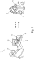
Figure 1 is a schematic overview of a welding apparatus according to an embodiment of the present invention; -
Figure 2 is a side view of a component of the apparatus offigure 1 ; -
Figure 3 is a detail perspective view of the component offigure 2 ; -
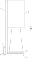
Figure 4 is a schematic view of a detail offigure 3 ; and -
Figure 5 is a schematic view representing the functioning of the welding apparatus offigures 1-4 . - The following description of exemplary embodiments refer to the accompanying drawings. The same reference numbers in different drawings identify the same or similar elements. The following detailed description does not limit the invention. Instead, the scope of the invention is defined by the appended claims.
- Reference throughout the specification to "one embodiment" or "an embodiment" means that a particular feature, structure, or characteristic described in connection with an embodiment is included in at least one embodiment of the subject matter disclosed. Thus, the appearance of the phrases "in one embodiment" or "in an embodiment" in various places throughout the specification is not necessarily referring to the same embodiment. Further, the particular features, structures or characteristics may be combined in any suitable manner in one or more embodiments.
- With reference to the attached drawings, with the number 1 is indicated a welding apparatus according to an embodiment of the present invention. It is to be noted that the welding apparatus 1 is designed to be tele-operated, however it is not required to be so. This will be better explained in a following part of the present disclosure.
- The welding apparatus 1 comprises a multi-axis system, for example the
robotic arm 2. The multi-axisrobotic arm 2 has afirst end 2a and asecond end 2b. In particular, the second end is fixed, for example on the ground or on a supporting structure, while thefirst end 2a can be moved with respect to thesecond end 2b in order to perform the welding process. - As can be seen in
figure 2 , in the preferred embodiment therobotic arm 2 has six degrees of freedom. Each degree of freedom is implemented as a rotation according to a respective rotation axis "X". Therobotic arm 2 itself should preferably be rated to withstand the high temperature and electromagnetic fields that are present in a welding environment. - According to another requirement, the
robotic arm 2 should be able to support the weight and the dynamics of the welding equipment which is installed on thefirst end 2a. Such welding equipment will be discussed in detail in a following part of the present disclosure. - A
welding tool 5 is attached to thefirst end 2a of therobotic arm 2. Thewelding tool 5 can be a GTAW welding torch. Alternatively, thewelding tool 5 can be a GMAW welding torch. Alternatively, thewelding tool 5 can be a SMAW welding handle. Alternatively, thewelding tool 5 can be a brazing handle. All of these implementations of thewelding tool 5 are by themselves known, and will not therefore be described in detail. - The welding apparatus also comprises a human-
machine interface 3, which allows the welder to interact with the apparatus and to pre-program the apparatus with welding parameters. For this purpose, and to allow the welder to monitor the process remotely, the human-machine interface 3 may comprise ascreen 26 and/or a3d visor 27, as schematically represented infigure 1 . - The welding apparatus 1 also comprises a control unit 8, which is configured to control at least the
robotic arm 2 and thewelding torch 5. Furthermore, the control unit 8 is configured to interact with the welder through the human-machine interface 3. Indeed, part of the logic of thecontrol unit 3 may be physically implemented in the human-machine interface 3. With more detail, the control unit 8 is preferably able to control all of the devices installed on the welding apparatus 1 in a manner which will be further clarified in a following part of the present disclosure. - The welding apparatus 1 may also comprise a
platform 15 for holding a work piece "WP" to be welded. This platform can either hold the work piece "WP" stationary or move it as needed. In this case, theplatform 15 is configured to move the work piece "W" with respect to thewelding torch 5. Furthermore, in this embodiment therobotic arm 2 can have any number of degrees of freedom. The exact number of degrees of freedom of therobotic arm 2 will be correlated to the mobility of theplatform 15, and will depend on the specific implementation. - As shown for example in
figures 2 and3 , animage acquisition device 4 is also attached to thefirst end 2a of therobotic arm 2. Theimage acquisition device 4 can be for example a camera. Theimage acquisition device 4 is configured to monitor a welding target 6. Moreover, theimage acquisition device 4 is able to provide an image of the welding target 6 to an operator. - The
image acquisition device 4 further comprises alight sensor 13, which can be of a known type and will not be described in further detail. - With more detail, the
image acquisition device 4 has alight filtering system 7. Thislight filtering system 7 can be active. Thelight filtering system 7 is placed in front of thelight sensor 13, in order to filter the light coming from the welding environment to thelight sensor 13. - As shown in detail in
figure 4 , thelight filtering system 7 comprises a first 11 and a secondpolarized lens 12. The activelight filtering system 7 can comprise amotor 14 associated to thelenses polarized lenses light sensor 13. Indeed, themotor 14 can rotate onelens light sensor 13 can be optically aligned with thelenses light filtering system 7, so that it receives the light passing through both lenses, or arranged externally with respect to theimage acquisition device 4. - In detail, light entering the
image acquisition device 4 enters through the firstpolarized lens 11, which gives it a preferred polarization. The light then crosses through thesecond lens 12. If the polarization axis of thelenses lenses lenses light filtering system 7 can be set to modulate the amount of light transit in a much simpler way than a mechanical diaphragm. Advantageously, this allow to employ theimage acquisition device 4 both when thewelding tool 5 is operating, thus emitting a considerable amount of light, and when it is not. - In an alternative embodiment, the
image acquisition device 4 can be a high-dynamic-range camera. A high-dynamic-range camera is a well-known type of camera, capable to actively refine the intensity of various wavelengths of light, which can be easily adapted and used for the scope. - In an alternative embodiment not shown in the drawings, the
image acquisition device 4 may comprise two cameras configured to provide a stereoscopic view of the welding target 6. Advantageously, with such embodiment it is possible to reconstruct a tridimensional image of the welding target 6, in order to further aid the operator particularly in the perception of depth. Furthermore, it is also possible to implement an augmented reality system thanks based on such tridimensional image. - The welding apparatus 1 may also comprise a
thermal sensor 16 placed on thefirst end 2a of therobotic arm 2. Thethermal sensor 16 is arranged to face the welding target 6, and is configured to provide a temperature field map of the welding target 6. The operator may use such information, for example, to detect the formation of the welding pool as well as to control in real-time the welding speed through thermal field. Preferably, thethermal sensor 16 is a thermal camera, which will not be described in detail because it is already known to the person skilled in the art. - The welding apparatus 1 may also comprise a
directional microphone 17, orientable toward the work piece "WP". Suchdirectional microphone 17 can also be placed on thefirst end 2a of the robotic arm, and is able to provide the operator with an audio feedback of the welding operation. For example, thedirectional microphone 17 allows to transmit to the welder noises created from the welding and possible mechanical shocks. - The welding apparatus 1 comprises a
scanner 18 positioned on thefirst end 2a of therobotic arm 2. Thescanner 18 is arranged so that it is upstream of thewelding tool 5 with respect to an advancing welding direction. Thescanner 18 is configured to provide substantially in real time a scan of at least part of the above mentioned work piece "WP". Thescanner 18 can be either a laser scanner, an optical scanner or any other kind of scanner suitable for this purpose according to the knowledge of the person skilled in the art. Since the laser scanner is by itself known, it will not be described in detail in the present disclosure. - The
scanner 18 allows to obtain the profile of the work piece "WP". Indeed, since thescanner 18 moves with therobotic arm 2, thescanner 18 is configured for continuously acquiring the profile of the work piece "WP". The control unit 8 can be configured to provide on thescreen 26 of the human-machine interface 3 a real-time image of the shape of the work piece "WP" profile. - As a function of the real-time scan of the work piece "WP", a preferred welding path is calculated through the control unit 8, providing instantaneously a welding direction that in any case can be manually adjusted by the operator.
- The welding apparatus 1 also comprises an
input interface 9 for a human operator. Preferably, theinput interface 9 is positioned remotely with respect to therobotic arm 2. - According to a preferred embodiment of the invention, the
input interface 9 comprises ahaptic interface 10. According to a further embodiment of the invention, not shown in the drawings, theinput interface 9 comprises a joystick. - Advantageously, with the
scanner 18 present, theinput interface 9 is configured to suggest a preferred welding direction as a function of the acquired profile of the work piece "WP". Specifically, thehaptic interface 10 can provide force feedback to the operator so that the operator is directed to proceed along the preferred welding direction. Indeed, the force feedback to the operator as a function of a predetermined set of welding parameters. - The operator however is still free to proceed in a different direction according to his own experience.
- Optionally, the
input interface 9 is configured to control thewelding tool 5 as a function of certain preset parameters. These parameters can be, for example, welding tension and/or welding voltage and/or welding torch speed and/or filler rod speed. - Referring now to
figure 5 , a possible implementation of the above mentioned control unit 8 will be described in detail.. The control unit 8 will be described as comprising several functional modules. These modules are referred to for ease and completeness of description, but they should not be considered structurally limiting. Indeed, all or part of these modules can be implemented in hardware and/or software. These modules may be part of the same physical device or may be located on different devices communicating among them using either a wired or wireless connection. These modules can interact with each other individually or as par of a network. Indeed, some of these modules may be part of a remote installation and interact with the other modules via Internet or other WAN. - The control unit 8 comprises a
control module 19 for therobotic arm 2. Thiscontrol module 19 comprises alocal unit 19a installed on therobotic arm 2, and aremote unit 19b which can be located remotely with respect to thelocal unit 19a. - The control unit 8 comprise a
scanner handling module 20 which is tasked with providing information related to the position of thescanner 18 to thecontrol module 19. - The
input interface 9 is associated with the control unit 8, and is configured to provide an input signal "SI" to the control unit 8. Through the input signal "SI" theinput interface 9 is able to control therobotic arm 2 substantially in real time. Indeed, the control unit 8 comprises aninterface handling module 21 which interacts with thecontrol module 19 for therobotic arm 2. - A welder handling module 22 is configured to interact with the
control module 19 of the robotic arm, to exchange information and/or input related to the function of thewelding tool 5, also in relation to the position of therobotic arm 2. Through the input signal "SI", the operator is thus able to control thewelding tool 5 substantially in real time. Also, acommand handling module 25 is present, through which the welder can change the welding parameters in the welder handling module 22 directly and/or control certain functions of the welding apparatus 1, depending on the specific implementation. - The welder handling module 22 interacts with a
camera handling module 23, which itself interfaces with theimage acquisition device 4. This module handles a video signal "SV" from theimage acquisition device 4, which can be redirected for example on thescreen 26. Thecamera handling module 23 also handles the setting of thelight filtering system 7, as explained above. - Optionally, the control unit 8 may also comprise a
thermal handling module 24. Suchthermal handling module 24 acquires data from thethermal sensor 16 and provides this information to the welder handling module 22. Optionally, thethermal handling module 24 may also show a representation of the temperature information to the welder on thescreen 26. - A method for performing a welding using the welding apparatus 1 comprises the first step of positioning a work piece "WP" to be welded on the welding target 6. The
welding tool 5 and therobotic arm 2 are then controlled by means of theinput interface 9 for performing the welding process. The work piece "WP" and the welding target 6 are monitored continuously by the operator at least through theimage acquisition device 4.
Claims (13)
- Welding apparatus (1) comprising a multi-axis robotic arm (2) having a first end (2a); a welding tool (5) attached to the first end (2a) and a control unit (8) configured to control the robotic arm (2) and the welding tool (5);the welding apparatus further comprising:an image acquisition device (4) attached to the first end (2a), having a light filtering system (7), said image acquisition device (4) being configured to monitor a welding target (6) on a workpiece (WP) and to provide an image of said welding target (6) to an operator;an input interface (9) for a human operator, said input interface (9) being associated to the control unit (8) and configured to provide an input signal (SI) to said control unit (8) and to control the robotic arm (2) and welding tool (5) substantially in real time;characterised by:a scanner (18) positioned on the first end (2a) of the robotic arm (2) upstream of the welding tool (5) with respect to an advancing welding direction and configured to provide substantially in real time a profile of the workpiece (WP), wherein the input interface (9) is configured to suggest instantaneously a preferred welding direction that in any case can be manually adjusted by the human operator as a function of said scan.
- Welding apparatus (1) according to claim 1, wherein the input interface (9) comprises a haptic interface (10) or a joystick.
- Welding apparatus (1) according to claim 1 or claim 2, wherein the input interface (9) is configured to provide a force feedback to the operator as a function of a predetermined set of welding parameters.
- Welding apparatus (1) according to any of the preceding claims, wherein the light filtering system (7) comprises a set of polarized lenses (11, 12).
- Welding apparatus (1) according to claim 4, wherein said image acquisition device (4) further comprises a light sensor (13) and a motor (14) for changing the configuration of said polarized lenses (11, 12) as a function on the light intensity sensed by said light sensor (13).
- Welding apparatus (1) according to any of the preceding claims, also comprising a thermal sensor (16) placed on the first end (2a) of the robotic arm (2), arranged to face said welding target (6) and configured to provide a temperature field map of the welding target (6).
- Welding apparatus (1) according to any of the preceding claims, wherein the image acquisition device (4) comprises at least two cameras configured to provide a stereoscopic view of the welding target (6).
- Welding apparatus (1) according to any of the preceding claims, also comprising a directional microphone (17) orientable toward the workpiece (WP).
- Welding apparatus (1) according to any of the preceding claims, wherein the welding tool (5) is a GTAW welding torch or a GMAW welding torch or a SMAW welding handle or a brazing tool.
- Welding apparatus (1) according to any of the preceding claims, further comprising a platform (15) for holding a work piece, said platform being configured to move the work piece with respect to the welding tool (5).
- Welding apparatus (1) according to any of the preceding claims, wherein the input interface (9) is configured to control the welding tool (5) as a function of welding tension and/or welding voltage and/or welding torch speed and/or filler rod speed.
- Method for performing a welding operation using a welding apparatus (1) according to any one of the previous claims, the method comprising the steps of positioning a work piece (WP) to be welded on the welding target (6); controlling the welding tool (5) and the robotic arm (2) by means of the input interface (9) to weld the work piece (WP); monitoring the work piece (WP) and the welding target (6) through the image acquisition device (4).
- Method according to claim 12, wherein the work piece (WP) is a turbomachine component.
Applications Claiming Priority (2)
| Application Number | Priority Date | Filing Date | Title |
|---|---|---|---|
| ITUB2016A000255A ITUB20160255A1 (en) | 2016-02-01 | 2016-02-01 | WELDING APPARATUS |
| PCT/EP2017/051949 WO2017134015A1 (en) | 2016-02-01 | 2017-01-30 | Welding apparatus |
Publications (2)
| Publication Number | Publication Date |
|---|---|
| EP3411176A1 EP3411176A1 (en) | 2018-12-12 |
| EP3411176B1 true EP3411176B1 (en) | 2023-10-11 |
Family
ID=55795099
Family Applications (1)
| Application Number | Title | Priority Date | Filing Date |
|---|---|---|---|
| EP17701891.8A Active EP3411176B1 (en) | 2016-02-01 | 2017-01-30 | Welding apparatus |
Country Status (6)
| Country | Link |
|---|---|
| US (1) | US20190047068A1 (en) |
| EP (1) | EP3411176B1 (en) |
| JP (1) | JP6912484B2 (en) |
| KR (1) | KR102600357B1 (en) |
| IT (1) | ITUB20160255A1 (en) |
| WO (1) | WO2017134015A1 (en) |
Families Citing this family (18)
| Publication number | Priority date | Publication date | Assignee | Title |
|---|---|---|---|---|
| EP3421167A1 (en) * | 2017-06-26 | 2019-01-02 | Fronius International GmbH | Method and device for sampling a workpiece surface of a metallic workpiece |
| IT201900000995A1 (en) * | 2019-01-23 | 2020-07-23 | Nuovo Pignone Tecnologie Srl | INDUSTRIAL ROBOTIC EQUIPMENT WITH IMPROVED PROCESSING PATH GENERATION AND METHOD TO OPERATE INDUSTRIAL ROBOTIC EQUIPMENT ACCORDING TO AN IMPROVED PROCESSING PATH |
| US10891841B2 (en) * | 2019-03-04 | 2021-01-12 | Alexander Favors | Apparatus and system for capturing criminals |
| US11311958B1 (en) * | 2019-05-13 | 2022-04-26 | Airgas, Inc. | Digital welding and cutting efficiency analysis, process evaluation and response feedback system for process optimization |
| CA3048300C (en) * | 2019-06-27 | 2023-10-17 | Servo-Robot Inc. | Twin laser camera assembly |
| CN110587073A (en) * | 2019-09-10 | 2019-12-20 | 上海交通大学 | Robot welding binocular vision sensing device based on micro stepping motor lead screw transmission |
| CN110788444A (en) * | 2019-11-28 | 2020-02-14 | 上海工程技术大学 | A device and method for dynamic detection of molten pool in arc additive manufacturing |
| KR102205827B1 (en) * | 2019-11-29 | 2021-01-21 | (주) 토탈소프트뱅크 | Virtualization system supporting welding |
| WO2022137116A1 (en) * | 2020-12-21 | 2022-06-30 | Liga Pietro | Welding workstation, vision kit for a welding workstation and vision method for welding operations |
| JP7594940B2 (en) * | 2021-03-02 | 2024-12-05 | 住友重機械工業株式会社 | Working Equipment |
| JP7541955B2 (en) * | 2021-05-06 | 2024-08-29 | 株式会社神戸製鋼所 | Robot travelling cart position determination device, method and program |
| KR102551337B1 (en) * | 2021-06-22 | 2023-07-07 | 주식회사 제이피에스 | strapping head monitoring system for packing coil through selective sensing of binding force of band for packing coil |
| IT202100017033A1 (en) * | 2021-06-29 | 2022-12-29 | Comau Spa | "Processing equipment and associated marking device for generating process trajectories" |
| US20230112463A1 (en) * | 2021-10-08 | 2023-04-13 | Edison Welding Institute, Inc. | Tele-manufacturing system |
| US12515272B2 (en) | 2022-06-06 | 2026-01-06 | Lincoln Global, Inc. | Weld angle correction device |
| EP4523841A1 (en) * | 2023-09-06 | 2025-03-19 | Lincoln Global, Inc. | Weld angle correction device |
| JP2025161474A (en) | 2024-04-12 | 2025-10-24 | 株式会社神戸製鋼所 | Remote monitoring system, remote monitoring method, data processing device, data processing method, terminal device and control method thereof, and program |
| CN119426876A (en) * | 2025-01-07 | 2025-02-14 | 浙江钱江机器人有限公司 | A multi-degree-of-freedom welding robot |
Citations (2)
| Publication number | Priority date | Publication date | Assignee | Title |
|---|---|---|---|---|
| JP2000176675A (en) * | 1998-12-17 | 2000-06-27 | Kawasaki Heavy Ind Ltd | Weld monitoring system with HMD |
| US20130119033A1 (en) * | 2011-11-11 | 2013-05-16 | Lincoln Global, Inc. | Mobile welding system and method |
Family Cites Families (16)
| Publication number | Priority date | Publication date | Assignee | Title |
|---|---|---|---|---|
| JPS53130245A (en) * | 1977-04-21 | 1978-11-14 | Osaka Transformer Co Ltd | Light shielding plate for welding |
| US4649426A (en) * | 1984-06-12 | 1987-03-10 | The United States Of America As Represented By The United States Department Of Energy | Electronic imaging system and technique |
| JPS6440291A (en) * | 1987-08-04 | 1989-02-10 | Meidensha Electric Mfg Co Ltd | Controller for robot |
| JP2606497B2 (en) * | 1991-08-27 | 1997-05-07 | 松下電器産業株式会社 | Arc welding robot system |
| JP3137254B2 (en) * | 1994-10-07 | 2001-02-19 | 新日本製鐵株式会社 | Automatic welding method |
| JPH0976063A (en) * | 1995-09-16 | 1997-03-25 | Sanshiyuuzen Kogyo Kk | Welding equipment |
| US6242711B1 (en) | 1999-12-27 | 2001-06-05 | Accudata, Inc. | Arc welding monitoring system |
| US6376801B1 (en) | 2000-10-12 | 2002-04-23 | General Electric Company | Gas turbine component refurbishment apparatus and repair method |
| SE521787C2 (en) * | 2002-04-05 | 2003-12-09 | Volvo Aero Corp | Device and method for controlling a welding area, arrangement and method for controlling a welding operation, computer program and computer program product |
| US20060049153A1 (en) * | 2004-09-08 | 2006-03-09 | Cahoon Christopher L | Dual feed laser welding system |
| US20060285330A1 (en) * | 2005-06-20 | 2006-12-21 | Ingvar Sundell | Automatic darkening filter with automatic power management |
| CN101745765B (en) | 2009-12-15 | 2012-02-08 | 哈尔滨工业大学 | Man-machine collaboration shared control remote welding method |
| KR101978740B1 (en) * | 2012-02-15 | 2019-05-15 | 삼성전자주식회사 | Tele-operation system and control method thereof |
| GB2506914A (en) * | 2012-10-12 | 2014-04-16 | Meta Vision Systems Ltd | Methods and systems for weld control |
| JP6018886B2 (en) * | 2012-11-20 | 2016-11-02 | 日立造船株式会社 | Welding method and welding unit |
| WO2014088994A1 (en) * | 2012-12-03 | 2014-06-12 | Abb Technology Ag | Teleoperation of machines having at least one actuated mechanism |
-
2016
- 2016-02-01 IT ITUB2016A000255A patent/ITUB20160255A1/en unknown
-
2017
- 2017-01-30 EP EP17701891.8A patent/EP3411176B1/en active Active
- 2017-01-30 US US16/074,580 patent/US20190047068A1/en not_active Abandoned
- 2017-01-30 JP JP2018539936A patent/JP6912484B2/en active Active
- 2017-01-30 KR KR1020187024198A patent/KR102600357B1/en active Active
- 2017-01-30 WO PCT/EP2017/051949 patent/WO2017134015A1/en not_active Ceased
Patent Citations (2)
| Publication number | Priority date | Publication date | Assignee | Title |
|---|---|---|---|---|
| JP2000176675A (en) * | 1998-12-17 | 2000-06-27 | Kawasaki Heavy Ind Ltd | Weld monitoring system with HMD |
| US20130119033A1 (en) * | 2011-11-11 | 2013-05-16 | Lincoln Global, Inc. | Mobile welding system and method |
Also Published As
| Publication number | Publication date |
|---|---|
| ITUB20160255A1 (en) | 2017-08-01 |
| WO2017134015A1 (en) | 2017-08-10 |
| KR20180109951A (en) | 2018-10-08 |
| JP6912484B2 (en) | 2021-08-04 |
| KR102600357B1 (en) | 2023-11-08 |
| EP3411176A1 (en) | 2018-12-12 |
| JP2019505391A (en) | 2019-02-28 |
| US20190047068A1 (en) | 2019-02-14 |
Similar Documents
| Publication | Publication Date | Title |
|---|---|---|
| KR102600357B1 (en) | welding device | |
| US10747393B2 (en) | User interface with real time pictograph representation of parameter settings | |
| EP3209451B1 (en) | Portable metal working robot system with communication circuitry and control system for virtually controlling a metal working process | |
| US11638968B2 (en) | Low energy, motion-assist, point-and-shoot welding torch | |
| KR102199207B1 (en) | TIG welding robot system using motion control of articulated robot | |
| KR102852259B1 (en) | A device for thermally joining at least one workpiece, comprising a torch and an extraction unit. | |
| JP6550985B2 (en) | Robot joining system | |
| US20170001268A1 (en) | Welding system | |
| US10780584B2 (en) | Remotely operated manual welding method and welding robot implementing such a method | |
| JP6327172B2 (en) | Laser welding system and laser welding method | |
| US11065706B2 (en) | Hybrid manual and automated welding | |
| US20240253161A1 (en) | Systems and methods to control laser application for handheld laser welding torches and laser welding equipment | |
| KR101362218B1 (en) | Apparatus for three dimensions weaving welding of horizontal butt | |
| Jones et al. | Development of a collaborative robot (COBOT) for increased welding productivity and quality in the shipyard | |
| WO2024163589A1 (en) | Systems and methods to control laser application for handheld laser welding torches and laser welding equipment | |
| JPH09295145A (en) | Automatic tube welding equipment | |
| CN121398940A (en) | Collaborative robot welding trajectory correction with intelligent vision | |
| JP2013193085A (en) | Welding system | |
| US20230356316A1 (en) | Welding assistance method for a robot device | |
| JP6027483B2 (en) | Arc welding method | |
| JP6411828B2 (en) | Camera position adjustment apparatus, welding robot system, and camera position adjustment method | |
| Begin et al. | Welding adaptive functions performed through infrared (IR) simplified vision schemes | |
| JP2014208354A (en) | Arc welding device | |
| Begin et al. | Welding adaptive functions performed through infrared simplified vision schemes |
Legal Events
| Date | Code | Title | Description |
|---|---|---|---|
| STAA | Information on the status of an ep patent application or granted ep patent |
Free format text: STATUS: UNKNOWN |
|
| STAA | Information on the status of an ep patent application or granted ep patent |
Free format text: STATUS: THE INTERNATIONAL PUBLICATION HAS BEEN MADE |
|
| PUAI | Public reference made under article 153(3) epc to a published international application that has entered the european phase |
Free format text: ORIGINAL CODE: 0009012 |
|
| STAA | Information on the status of an ep patent application or granted ep patent |
Free format text: STATUS: REQUEST FOR EXAMINATION WAS MADE |
|
| 17P | Request for examination filed |
Effective date: 20180903 |
|
| AK | Designated contracting states |
Kind code of ref document: A1 Designated state(s): AL AT BE BG CH CY CZ DE DK EE ES FI FR GB GR HR HU IE IS IT LI LT LU LV MC MK MT NL NO PL PT RO RS SE SI SK SM TR |
|
| AX | Request for extension of the european patent |
Extension state: BA ME |
|
| DAV | Request for validation of the european patent (deleted) | ||
| DAX | Request for extension of the european patent (deleted) | ||
| STAA | Information on the status of an ep patent application or granted ep patent |
Free format text: STATUS: EXAMINATION IS IN PROGRESS |
|
| 17Q | First examination report despatched |
Effective date: 20200615 |
|
| GRAP | Despatch of communication of intention to grant a patent |
Free format text: ORIGINAL CODE: EPIDOSNIGR1 |
|
| STAA | Information on the status of an ep patent application or granted ep patent |
Free format text: STATUS: GRANT OF PATENT IS INTENDED |
|
| INTG | Intention to grant announced |
Effective date: 20230508 |
|
| P01 | Opt-out of the competence of the unified patent court (upc) registered |
Effective date: 20230526 |
|
| GRAS | Grant fee paid |
Free format text: ORIGINAL CODE: EPIDOSNIGR3 |
|
| GRAA | (expected) grant |
Free format text: ORIGINAL CODE: 0009210 |
|
| STAA | Information on the status of an ep patent application or granted ep patent |
Free format text: STATUS: THE PATENT HAS BEEN GRANTED |
|
| AK | Designated contracting states |
Kind code of ref document: B1 Designated state(s): AL AT BE BG CH CY CZ DE DK EE ES FI FR GB GR HR HU IE IS IT LI LT LU LV MC MK MT NL NO PL PT RO RS SE SI SK SM TR |
|
| RAP3 | Party data changed (applicant data changed or rights of an application transferred) |
Owner name: NUOVO PIGNONE TECNOLOGIE - S.R.L. |
|
| REG | Reference to a national code |
Ref country code: GB Ref legal event code: FG4D |
|
| REG | Reference to a national code |
Ref country code: CH Ref legal event code: EP |
|
| REG | Reference to a national code |
Ref country code: DE Ref legal event code: R096 Ref document number: 602017075136 Country of ref document: DE |
|
| REG | Reference to a national code |
Ref country code: IE Ref legal event code: FG4D |
|
| REG | Reference to a national code |
Ref country code: SE Ref legal event code: TRGR |
|
| REG | Reference to a national code |
Ref country code: NO Ref legal event code: T2 Effective date: 20231011 |
|
| REG | Reference to a national code |
Ref country code: LT Ref legal event code: MG9D |
|
| REG | Reference to a national code |
Ref country code: NL Ref legal event code: MP Effective date: 20231011 |
|
| REG | Reference to a national code |
Ref country code: AT Ref legal event code: MK05 Ref document number: 1619714 Country of ref document: AT Kind code of ref document: T Effective date: 20231011 |
|
| PG25 | Lapsed in a contracting state [announced via postgrant information from national office to epo] |
Ref country code: NL Free format text: LAPSE BECAUSE OF FAILURE TO SUBMIT A TRANSLATION OF THE DESCRIPTION OR TO PAY THE FEE WITHIN THE PRESCRIBED TIME-LIMIT Effective date: 20231011 |
|
| PG25 | Lapsed in a contracting state [announced via postgrant information from national office to epo] |
Ref country code: GR Free format text: LAPSE BECAUSE OF FAILURE TO SUBMIT A TRANSLATION OF THE DESCRIPTION OR TO PAY THE FEE WITHIN THE PRESCRIBED TIME-LIMIT Effective date: 20240112 |
|
| PG25 | Lapsed in a contracting state [announced via postgrant information from national office to epo] |
Ref country code: IS Free format text: LAPSE BECAUSE OF FAILURE TO SUBMIT A TRANSLATION OF THE DESCRIPTION OR TO PAY THE FEE WITHIN THE PRESCRIBED TIME-LIMIT Effective date: 20240211 |
|
| PG25 | Lapsed in a contracting state [announced via postgrant information from national office to epo] |
Ref country code: LT Free format text: LAPSE BECAUSE OF FAILURE TO SUBMIT A TRANSLATION OF THE DESCRIPTION OR TO PAY THE FEE WITHIN THE PRESCRIBED TIME-LIMIT Effective date: 20231011 |
|
| PG25 | Lapsed in a contracting state [announced via postgrant information from national office to epo] |
Ref country code: AT Free format text: LAPSE BECAUSE OF FAILURE TO SUBMIT A TRANSLATION OF THE DESCRIPTION OR TO PAY THE FEE WITHIN THE PRESCRIBED TIME-LIMIT Effective date: 20231011 |
|
| PG25 | Lapsed in a contracting state [announced via postgrant information from national office to epo] |
Ref country code: ES Free format text: LAPSE BECAUSE OF FAILURE TO SUBMIT A TRANSLATION OF THE DESCRIPTION OR TO PAY THE FEE WITHIN THE PRESCRIBED TIME-LIMIT Effective date: 20231011 |
|
| PG25 | Lapsed in a contracting state [announced via postgrant information from national office to epo] |
Ref country code: LT Free format text: LAPSE BECAUSE OF FAILURE TO SUBMIT A TRANSLATION OF THE DESCRIPTION OR TO PAY THE FEE WITHIN THE PRESCRIBED TIME-LIMIT Effective date: 20231011 Ref country code: IS Free format text: LAPSE BECAUSE OF FAILURE TO SUBMIT A TRANSLATION OF THE DESCRIPTION OR TO PAY THE FEE WITHIN THE PRESCRIBED TIME-LIMIT Effective date: 20240211 Ref country code: GR Free format text: LAPSE BECAUSE OF FAILURE TO SUBMIT A TRANSLATION OF THE DESCRIPTION OR TO PAY THE FEE WITHIN THE PRESCRIBED TIME-LIMIT Effective date: 20240112 Ref country code: ES Free format text: LAPSE BECAUSE OF FAILURE TO SUBMIT A TRANSLATION OF THE DESCRIPTION OR TO PAY THE FEE WITHIN THE PRESCRIBED TIME-LIMIT Effective date: 20231011 Ref country code: BG Free format text: LAPSE BECAUSE OF FAILURE TO SUBMIT A TRANSLATION OF THE DESCRIPTION OR TO PAY THE FEE WITHIN THE PRESCRIBED TIME-LIMIT Effective date: 20240111 Ref country code: AT Free format text: LAPSE BECAUSE OF FAILURE TO SUBMIT A TRANSLATION OF THE DESCRIPTION OR TO PAY THE FEE WITHIN THE PRESCRIBED TIME-LIMIT Effective date: 20231011 Ref country code: PT Free format text: LAPSE BECAUSE OF FAILURE TO SUBMIT A TRANSLATION OF THE DESCRIPTION OR TO PAY THE FEE WITHIN THE PRESCRIBED TIME-LIMIT Effective date: 20240212 |
|
| PG25 | Lapsed in a contracting state [announced via postgrant information from national office to epo] |
Ref country code: RS Free format text: LAPSE BECAUSE OF FAILURE TO SUBMIT A TRANSLATION OF THE DESCRIPTION OR TO PAY THE FEE WITHIN THE PRESCRIBED TIME-LIMIT Effective date: 20231011 Ref country code: PL Free format text: LAPSE BECAUSE OF FAILURE TO SUBMIT A TRANSLATION OF THE DESCRIPTION OR TO PAY THE FEE WITHIN THE PRESCRIBED TIME-LIMIT Effective date: 20231011 Ref country code: LV Free format text: LAPSE BECAUSE OF FAILURE TO SUBMIT A TRANSLATION OF THE DESCRIPTION OR TO PAY THE FEE WITHIN THE PRESCRIBED TIME-LIMIT Effective date: 20231011 Ref country code: HR Free format text: LAPSE BECAUSE OF FAILURE TO SUBMIT A TRANSLATION OF THE DESCRIPTION OR TO PAY THE FEE WITHIN THE PRESCRIBED TIME-LIMIT Effective date: 20231011 |
|
| PG25 | Lapsed in a contracting state [announced via postgrant information from national office to epo] |
Ref country code: DK Free format text: LAPSE BECAUSE OF FAILURE TO SUBMIT A TRANSLATION OF THE DESCRIPTION OR TO PAY THE FEE WITHIN THE PRESCRIBED TIME-LIMIT Effective date: 20231011 |
|
| REG | Reference to a national code |
Ref country code: DE Ref legal event code: R097 Ref document number: 602017075136 Country of ref document: DE |
|
| PG25 | Lapsed in a contracting state [announced via postgrant information from national office to epo] |
Ref country code: CZ Free format text: LAPSE BECAUSE OF FAILURE TO SUBMIT A TRANSLATION OF THE DESCRIPTION OR TO PAY THE FEE WITHIN THE PRESCRIBED TIME-LIMIT Effective date: 20231011 |
|
| PG25 | Lapsed in a contracting state [announced via postgrant information from national office to epo] |
Ref country code: SK Free format text: LAPSE BECAUSE OF FAILURE TO SUBMIT A TRANSLATION OF THE DESCRIPTION OR TO PAY THE FEE WITHIN THE PRESCRIBED TIME-LIMIT Effective date: 20231011 |
|
| PG25 | Lapsed in a contracting state [announced via postgrant information from national office to epo] |
Ref country code: SM Free format text: LAPSE BECAUSE OF FAILURE TO SUBMIT A TRANSLATION OF THE DESCRIPTION OR TO PAY THE FEE WITHIN THE PRESCRIBED TIME-LIMIT Effective date: 20231011 Ref country code: SK Free format text: LAPSE BECAUSE OF FAILURE TO SUBMIT A TRANSLATION OF THE DESCRIPTION OR TO PAY THE FEE WITHIN THE PRESCRIBED TIME-LIMIT Effective date: 20231011 Ref country code: RO Free format text: LAPSE BECAUSE OF FAILURE TO SUBMIT A TRANSLATION OF THE DESCRIPTION OR TO PAY THE FEE WITHIN THE PRESCRIBED TIME-LIMIT Effective date: 20231011 Ref country code: IT Free format text: LAPSE BECAUSE OF FAILURE TO SUBMIT A TRANSLATION OF THE DESCRIPTION OR TO PAY THE FEE WITHIN THE PRESCRIBED TIME-LIMIT Effective date: 20231011 Ref country code: EE Free format text: LAPSE BECAUSE OF FAILURE TO SUBMIT A TRANSLATION OF THE DESCRIPTION OR TO PAY THE FEE WITHIN THE PRESCRIBED TIME-LIMIT Effective date: 20231011 Ref country code: DK Free format text: LAPSE BECAUSE OF FAILURE TO SUBMIT A TRANSLATION OF THE DESCRIPTION OR TO PAY THE FEE WITHIN THE PRESCRIBED TIME-LIMIT Effective date: 20231011 Ref country code: CZ Free format text: LAPSE BECAUSE OF FAILURE TO SUBMIT A TRANSLATION OF THE DESCRIPTION OR TO PAY THE FEE WITHIN THE PRESCRIBED TIME-LIMIT Effective date: 20231011 |
|
| PLBE | No opposition filed within time limit |
Free format text: ORIGINAL CODE: 0009261 |
|
| STAA | Information on the status of an ep patent application or granted ep patent |
Free format text: STATUS: NO OPPOSITION FILED WITHIN TIME LIMIT |
|
| PG25 | Lapsed in a contracting state [announced via postgrant information from national office to epo] |
Ref country code: MC Free format text: LAPSE BECAUSE OF FAILURE TO SUBMIT A TRANSLATION OF THE DESCRIPTION OR TO PAY THE FEE WITHIN THE PRESCRIBED TIME-LIMIT Effective date: 20231011 |
|
| PG25 | Lapsed in a contracting state [announced via postgrant information from national office to epo] |
Ref country code: MC Free format text: LAPSE BECAUSE OF FAILURE TO SUBMIT A TRANSLATION OF THE DESCRIPTION OR TO PAY THE FEE WITHIN THE PRESCRIBED TIME-LIMIT Effective date: 20231011 |
|
| PG25 | Lapsed in a contracting state [announced via postgrant information from national office to epo] |
Ref country code: LU Free format text: LAPSE BECAUSE OF NON-PAYMENT OF DUE FEES Effective date: 20240130 |
|
| 26N | No opposition filed |
Effective date: 20240712 |
|
| PG25 | Lapsed in a contracting state [announced via postgrant information from national office to epo] |
Ref country code: LU Free format text: LAPSE BECAUSE OF NON-PAYMENT OF DUE FEES Effective date: 20240130 |
|
| PG25 | Lapsed in a contracting state [announced via postgrant information from national office to epo] |
Ref country code: BE Free format text: LAPSE BECAUSE OF NON-PAYMENT OF DUE FEES Effective date: 20240131 |
|
| PG25 | Lapsed in a contracting state [announced via postgrant information from national office to epo] |
Ref country code: FR Free format text: LAPSE BECAUSE OF NON-PAYMENT OF DUE FEES Effective date: 20240131 |
|
| PG25 | Lapsed in a contracting state [announced via postgrant information from national office to epo] |
Ref country code: SI Free format text: LAPSE BECAUSE OF FAILURE TO SUBMIT A TRANSLATION OF THE DESCRIPTION OR TO PAY THE FEE WITHIN THE PRESCRIBED TIME-LIMIT Effective date: 20231011 |
|
| PG25 | Lapsed in a contracting state [announced via postgrant information from national office to epo] |
Ref country code: SI Free format text: LAPSE BECAUSE OF FAILURE TO SUBMIT A TRANSLATION OF THE DESCRIPTION OR TO PAY THE FEE WITHIN THE PRESCRIBED TIME-LIMIT Effective date: 20231011 Ref country code: FR Free format text: LAPSE BECAUSE OF NON-PAYMENT OF DUE FEES Effective date: 20240131 Ref country code: BE Free format text: LAPSE BECAUSE OF NON-PAYMENT OF DUE FEES Effective date: 20240131 |
|
| REG | Reference to a national code |
Ref country code: BE Ref legal event code: MM Effective date: 20240131 |
|
| PG25 | Lapsed in a contracting state [announced via postgrant information from national office to epo] |
Ref country code: IE Free format text: LAPSE BECAUSE OF NON-PAYMENT OF DUE FEES Effective date: 20240130 |
|
| PG25 | Lapsed in a contracting state [announced via postgrant information from national office to epo] |
Ref country code: IE Free format text: LAPSE BECAUSE OF NON-PAYMENT OF DUE FEES Effective date: 20240130 |
|
| PG25 | Lapsed in a contracting state [announced via postgrant information from national office to epo] |
Ref country code: CY Free format text: LAPSE BECAUSE OF FAILURE TO SUBMIT A TRANSLATION OF THE DESCRIPTION OR TO PAY THE FEE WITHIN THE PRESCRIBED TIME-LIMIT; INVALID AB INITIO Effective date: 20170130 |
|
| PG25 | Lapsed in a contracting state [announced via postgrant information from national office to epo] |
Ref country code: HU Free format text: LAPSE BECAUSE OF FAILURE TO SUBMIT A TRANSLATION OF THE DESCRIPTION OR TO PAY THE FEE WITHIN THE PRESCRIBED TIME-LIMIT; INVALID AB INITIO Effective date: 20170130 |
|
| PG25 | Lapsed in a contracting state [announced via postgrant information from national office to epo] |
Ref country code: FI Free format text: LAPSE BECAUSE OF FAILURE TO SUBMIT A TRANSLATION OF THE DESCRIPTION OR TO PAY THE FEE WITHIN THE PRESCRIBED TIME-LIMIT Effective date: 20231011 |
|
| PG25 | Lapsed in a contracting state [announced via postgrant information from national office to epo] |
Ref country code: TR Free format text: LAPSE BECAUSE OF FAILURE TO SUBMIT A TRANSLATION OF THE DESCRIPTION OR TO PAY THE FEE WITHIN THE PRESCRIBED TIME-LIMIT Effective date: 20231011 |
|
| PGFP | Annual fee paid to national office [announced via postgrant information from national office to epo] |
Ref country code: GB Payment date: 20251220 Year of fee payment: 10 |
|
| PGFP | Annual fee paid to national office [announced via postgrant information from national office to epo] |
Ref country code: NO Payment date: 20251218 Year of fee payment: 10 |
|
| PGFP | Annual fee paid to national office [announced via postgrant information from national office to epo] |
Ref country code: SE Payment date: 20251217 Year of fee payment: 10 |
|
| REG | Reference to a national code |
Ref country code: CH Ref legal event code: U11 Free format text: ST27 STATUS EVENT CODE: U-0-0-U10-U11 (AS PROVIDED BY THE NATIONAL OFFICE) Effective date: 20260201 |
|
| PGFP | Annual fee paid to national office [announced via postgrant information from national office to epo] |
Ref country code: DE Payment date: 20251217 Year of fee payment: 10 |
|
| PGFP | Annual fee paid to national office [announced via postgrant information from national office to epo] |
Ref country code: CH Payment date: 20260201 Year of fee payment: 10 |