EP3410951B1 - Implantable textile anchor - Google Patents
Implantable textile anchor Download PDFInfo
- Publication number
- EP3410951B1 EP3410951B1 EP17702787.7A EP17702787A EP3410951B1 EP 3410951 B1 EP3410951 B1 EP 3410951B1 EP 17702787 A EP17702787 A EP 17702787A EP 3410951 B1 EP3410951 B1 EP 3410951B1
- Authority
- EP
- European Patent Office
- Prior art keywords
- anchor
- filament
- collapsible member
- eyelets
- filaments
- Prior art date
- Legal status (The legal status is an assumption and is not a legal conclusion. Google has not performed a legal analysis and makes no representation as to the accuracy of the status listed.)
- Active
Links
Images




Classifications
-
- A—HUMAN NECESSITIES
- A61—MEDICAL OR VETERINARY SCIENCE; HYGIENE
- A61B—DIAGNOSIS; SURGERY; IDENTIFICATION
- A61B17/00—Surgical instruments, devices or methods
- A61B17/04—Surgical instruments, devices or methods for suturing wounds; Holders or packages for needles or suture materials
- A61B17/0401—Suture anchors, buttons or pledgets, i.e. means for attaching sutures to bone, cartilage or soft tissue; Instruments for applying or removing suture anchors
-
- A—HUMAN NECESSITIES
- A61—MEDICAL OR VETERINARY SCIENCE; HYGIENE
- A61B—DIAGNOSIS; SURGERY; IDENTIFICATION
- A61B17/00—Surgical instruments, devices or methods
- A61B17/04—Surgical instruments, devices or methods for suturing wounds; Holders or packages for needles or suture materials
- A61B17/0401—Suture anchors, buttons or pledgets, i.e. means for attaching sutures to bone, cartilage or soft tissue; Instruments for applying or removing suture anchors
- A61B2017/0403—Dowels
-
- A—HUMAN NECESSITIES
- A61—MEDICAL OR VETERINARY SCIENCE; HYGIENE
- A61B—DIAGNOSIS; SURGERY; IDENTIFICATION
- A61B17/00—Surgical instruments, devices or methods
- A61B17/04—Surgical instruments, devices or methods for suturing wounds; Holders or packages for needles or suture materials
- A61B17/0401—Suture anchors, buttons or pledgets, i.e. means for attaching sutures to bone, cartilage or soft tissue; Instruments for applying or removing suture anchors
- A61B2017/0409—Instruments for applying suture anchors
-
- A—HUMAN NECESSITIES
- A61—MEDICAL OR VETERINARY SCIENCE; HYGIENE
- A61B—DIAGNOSIS; SURGERY; IDENTIFICATION
- A61B17/00—Surgical instruments, devices or methods
- A61B17/04—Surgical instruments, devices or methods for suturing wounds; Holders or packages for needles or suture materials
- A61B17/0401—Suture anchors, buttons or pledgets, i.e. means for attaching sutures to bone, cartilage or soft tissue; Instruments for applying or removing suture anchors
- A61B2017/0446—Means for attaching and blocking the suture in the suture anchor
- A61B2017/0459—Multiple holes in the anchor through which the suture extends and locking the suture when tension is applied
Definitions
- the invention relates to an implantable textile anchor comprising a collapsible member and at least one filament for collapsing the member.
- Surgical procedures often involve the use of fixation means, which are fastened e.g. in a hole produced in a bone or soft tissue.
- Textile anchors for instance in the form of so-called “all-suture based anchors", can be used as such fixation means.
- the textile anchor is inserted into the hole in an initial state, in which it has a slender form, and then transformed into a collapsed state, in which the anchor has a laterally expanded form, whereby it is fixed in the hole.
- a filament serving as a suture is threaded through the tissue (such as a ligament, tendon, or cartilage) which is to be attached to the bone. The suture is then secured to fasten the tissue in place.
- the document US 2011/0270278 A1 discloses an anchor including an anchor body, which is formed by a braided strand having a plurality of openings and with which an actuation strand can be made integral. Only one end is available for handling, which makes it difficult to securely fix the anchor.
- the document discloses another anchor including an anchor body, which is formed by a mesh and which has an eyelet. The actuating strand is put therethrough without any attachment. This has the risk that the strand may be displaced so that the anchor cannot be securely fixed.
- an anchor comprising a collapsible member which is braided to form bifurcating and converging portions which define eyelets allows a simplified fabrication, as it is e.g. not necessary to create manually a plurality of loops for defining openings.
- the eyelets of the collapsible member define definite openings in the member for guiding through a filament.
- the anchor can be securely fixed by the provision of at least one filament, which is knotted to an eyelet and/or which together with at least a second filament is made integral with the collapsible member.
- the anchor comprises one or more of the following features:
- Fig. 1 shows a flexible slender structure, which comprises a plurality of eyelets 5 passing therethrough.
- an eyelet 5 defines an opening which extends from one side of the structure to its other side.
- a portion with a predetermined length is cut off from the structure of Fig. 1 .
- the latter is a textile which is braided such that, in an alternating fashion, it bifurcates at a central portion 3 into two separated branch portions 4a, 4b, which converge again at an adjacent central portion 3 to form an eyelet 5.
- the length Lc of the central portions 3 and the length Le of the eyelets 5 may be the same or may vary.
- each central portion 3 is shown as having the same width Wc and each branch portion 4a, 4b is shown as having the same width We. It is also conceivable that the width Wc of the central portions 3 and/or the width We of the branch portions 4a, 4b vary.
- the interior 7, 7a, 7b of these formed tubes may include a core.
- the core may include for instance strands, which are straight, twisted or braided.
- the core may be made of one or more of the following materials: textile material, non-textile material, metal, plastic, etc.
- the core may include e.g. a tube, in particular a plastic tube, a monofilament, a monofilament with embedded particles that can be released over time (drug delivery system), a metal wire, a mesh, a webbing, etc.
- Machines arranged for tubular braiding cause the yarn carriers to move in a circle. This results in a tubular structure having an interior, which may or may not include a core. Machines arranged for flat braiding cause the yarn carriers to move on a line back and forth. This results in a flat structure without an interior.
- Fig. 4 shows an example of an anchor comprising a collapsible member 1 having a first end 1a, a second 1b as well as a plurality of eyelets 5 arranged therebetween and a filament 10 passed through at least some of the eyelets 5.
- the collapsible member 1 may be produced e.g. by cutting off a portion from the structure of Fig. 1 .
- the filament 10 is a flexible member separate from the collapsible member 1 and may have a suture- or lace-like structure.
- the filament 10 is interconnected with the collapsible member 1 such that when pulling thereon the member 1 collapses to form a folded structure having an increased lateral extension (see Fig. 5 ).
- the side of the member 1 visible in Fig. 4 is designated as the front side, while the non-visible side is the rear side.
- the filament 10 is folded in the middle to form a loop portion 10c arranged at the front side of the member 10.
- Both ends 10a and 10b of the filament 10 are passed from the rear side of the member 1 through the first eyelet 5a arranged at the end 1a and through the loop portion 10c, so that a knot is formed, and are directed through the last eyelet 5b arranged at the end 1b.
- the two ends 10a, 10b are guided together in alternating fashion through the eyelets 5 from one side of the member 1 to the other side.
- the ends 10a, 10b are led once more straight through the first eyelet 5a.
- Fig. 5 shows an example of an anchor 1, 10 implanted in the bone B of a patient.
- the layer C refers to the cortex, which is the outer shell of the bone B.
- the surgeon drills a hole H into the bone B, pushes the member 1 thereinto by means of a suitable instrument and pulls on the ends 10a, 10b of the filament 10, so that the member 1 adopts a collapsed structure, which is firmly anchored in the bone B.
- Fig. 6 shows a variant of the anchor of Fig. 4 , in which the ends 10a and 10b of the filament 10 are guided from the last eyelet 5b to the first eyelet 5a not in parallel, but in a crossed fashion. Thus, the ends 10a and 10b pass through opposite sides at each eyelet 5, 5a, 5b.
- Fig. 7 shows a variant of the anchor, in which the first end 10a of the filament 10 is directed through the first eyelet 5a of the member 1 and knotted together at a position 10d.
- the other (free) end 10b is directed through the last eyelet 5b and is led subsequently in an alternating manner through the eyelets 5 from one side of the member 1 to the other side.
- the anchor 1, 10 forms a so-called single-filament-loaded anchor, which has only one end 10b utilizable for fixation.
- Fig. 8 shows another variant of the anchor, in which the filament 10 is directed through the eyelets 5 alternatingly from one side of the member 1 to its other side.
- the filament 10 is fixed in the area of the middle of the member 1, so that it cannot be shifted as a whole relative to the member 1.
- the filament 10 is guided e.g. through the eyelet 5c to form a knot 10e.
- a second filament 8 which is guided through the eyelets 5 in parallel with the filament 10 as shown in Fig. 9 .
- the second filament 8 is attached in the middle of the member 1, for instance it is knotted to a branch portion of the eyelet 5c in a similar way as the filament 10.
- Fig. 10 shows a variant of the anchor of Fig. 9 , in which the first filament 10 and the second filament 8 are guided through the eyelets not in parallel, but in a crossed manner. Thus, the filaments 8 and 10 pass through opposite sides at each eyelet. The first and second filaments 8, 10 are guided e.g. through the eyelet 5c to form a knot 8e and a knot 10e, respectively.
- Fig. 11 and 12 show part of an instrument 20 suitable to apply an anchor at a specific location in the body of a patient.
- the instrument 20 comprises a cannula 21 defining a tube which is open at the distal end and which serves for receiving a stopper element 22, an inserter element 23 and an anchor, e.g. the anchor 1, 10 of Fig. 8 .
- the distal end of the cannula 21 may have a tapered or straight form.
- the elements 22 and 23 are arranged such in the cannula 21 that they are movable relative to each other.
- the stopper element 22 has at its distal end a stopper face 22a and includes a boring 22b through which the inserter element 23 and the ends 10a, 10b of the filament 10 extend.
- the inserter element 23, which has here the form of a rod, comprises an end 23a to act on the anchor 1, 10.
- the member 1 is arranged in a U-shaped form along the end 23a of the inserter element 23
- the elements 22, 23 together with the anchor 1, 10 are moved forward, such that the member 1 and the end 23a emerge out of the cannula 21 and into the cavity, where the anchor 1 is to be applied. Subsequently, the inserter element 23 is retracted, whereas the stopper element 22 remains at the same position, which is on the cortex, in case the cavity is a hole in bone. Thereby, the anchor 1, 10 abuts the stopper face 22a to ensure that it remains in the cavity. After first pulling the ends 10a, 10b to collapse the member 1, the whole instrument 20 is finally removed.
- Fig. 13 shows another variant of the anchor.
- the filament 10 is folded in the middle to form a loop portion 10c arranged at the front side of the member 1.
- Both ends 10a and 10b of the filament 10 are passed from the rear side of the member 1 through the second eyelet 5d arranged at the end 1a and through the loop portion 10c and are directed through the last eyelet 5b arranged at the end 1b, so that the ends 10a, 10b pass therethrough from opposite sides of the member 1.
- the two ends 10a, 10b are guided alternatingly through the eyelets 5 from one side of the member 1 to the other side, such that in each case the ends 10a, 10b pass therethrough from opposite sides of the member 1.
- the anchor comprises a second filament 9, which is guided through the first eyelet 5a at the end 1a, so that it can be shifted as a whole relative to the member 1.
- the two filaments 9 and 10 may have for instance different colors.
- the surgeon pushes the member 1 by means of a suitable instrument into a hole H, which is drilled e.g. in the bone of a patient, and pulls on the ends 10a, 10b of the filament 10, so that the member 1 adopts a collapsed structure, see Fig. 15 .
- the ends 10a, 10b are knotted together alone or by fixing another part forming a knot 10g.
- the second filament 9, whose ends are arranged outside of the hole H and which is shiftable relative to the member 1, can be used for fixation of another part, such as a ligament, tendon or bone.
- Fig. 13 The location, where the second filament 9 is guided through an eyelet, the location with the loop portion 10c and the location, where the free ends 10a, 10b crosses the last time in an eyelet, are in the anchor of Fig. 13 at the first eyelet 5a and the second eyelet 5b, respectively. These locations may be chosen at other eyelets.
- Fig. 14 shows an example, where said three locations are arranged at the first eyelet 5a.
- Fig. 16 shows part of an instrument 30 suitable to introduce an anchor in particular in soft tissue of a patient.
- the instrument 30 may also be used to apply an anchor to hard tissue. It comprises a cannula 31 defining a tube which is open at the distal end and which serves for receiving a pusher element 32 and an anchor, e.g. the anchor 1, 10 of Fig. 14 with or without the second filament 9.
- the pusher element 32 includes a groove 32a, which extends along its longitudinal axis and in which the ends 10a, 10b of the filament 10 are received.
- the anchor includes a second filament, e.g. filament 9 in Fig. 14
- the groove 32a is configured such that the ends of both filaments 9 and 10 can be accommodated therein.
- the pusher element 32 may have a bore extending along its longitudinal axis.
- the end of the instrument 30 is introduced into the hole, which is formed e.g. in soft tissue, the pusher element 32 is moved forward, so that the anchor is freed out of the interior of the cannula 31.
- pulling on the ends 10a, 10b causes the member 1 to collapse.
- Fig. 17 shows another example of a flexible slender structure which can be used to form an anchor of a second kind.
- the structure comprises first parts P1 and second parts P2, which are arranged in an alternating manner along the structure.
- Each first part P1 comprises a plurality of eyelets 5 passing through the structure, whereas each second part P2 is free of eyelets 5.
- the second part P2 is similar to a central portion 3 of the first part P1, however with a longer length and, typically, with a smaller width.
- the number of strands for braiding the second parts P2 may be the same or smaller than the number of strands for braiding the first parts P1.
- the number of eyelets 5 and their dimension may be chosen with regard to the specific needs of the anchor.
- the length of a part P2 is greater than that of a part P1, so that it can be passed through eyelets 5 of the part P1 as described further below.
- the structure with the parts P1, P2 is braided such that its strands bifurcate and converge to form the parts P2 and the parts P1 with the eyelets 5 and the central portions 3. Similar as in the example of Fig. 2 , the parts P1 and P2 have tubular braids with or without a core.
- Fig. 17 may be cut in each case in the middle of each second part P2 (see location ps in Fig. 17 ) resulting in anchors with a symmetrical form (see Fig. 18 ).
- the anchor shown in Fig. 18 comprises a collapsible member 1 formed by a first part P1 of the structure of Fig. 17 and two filaments 12 and 13 formed by second parts P2 adjacent to the first part P1. As the anchor is braided as a whole, the filaments 12 and 13 are made integral with the member 1.
- the member 1 has an eyelet 5c in the middle between both ends 1a and 1b, which is left free and which may be used to cooperate with the end 43a of an inserter element 43 (see Fig. 19 ).
- the end 12b of the filament 12 is guided through an eyelet 5d adjacent to the eyelet 5c in the middle and then through the following eyelet(s) 5 from one side to the other side of the member 1 up to the eyelet 5a at the end 1a of the member 1.
- the second filament 13 is arranged in a symmetrical way to the first filament 12 by guiding its end 13b through an eyelet 5e adjacent to the eyelet 5c in the middle and then through the following eyelet(s) 5 from one side to the other side of the member 1 up to the eyelet 5b at the end 1b of the member 1.
- Fig. 19 shows part of an instrument 40 suitable to introduce an anchor in particular in hard tissue, such as bone.
- the instrument 40 may also be used to apply an anchor to soft tissue. It comprises a cannula 41 defining a tube which is open at the distal end and which serves for receiving a stopper element 42, an inserter element 43 and an anchor, e.g. the anchor 1, 12, 13 of Fig. 18 .
- the elements 42 and 43 are arranged such in the cannula 41 that they are movable relative to each other.
- the stopper element 42 has at its distal end a stopper face 42a and includes a boring 42b through which the inserter element 43 and the ends 12b, 13b of the filaments 12, 13 extend.
- the inserter element 43 which has here the form of a rod, comprises an end 43a.
- the anchor 1, 12, 13 is arranged in a U-shaped form within the cannula 41, so that the end 43a of the inserter element 43 can pass through the eyelet 5c in the middle of the member 1.
- the surgeon drills with a suitable drill 48 a hole H e.g. into the bone B of a patient as shown in Fig. 20 .
- the cannula 41 of the instrument 40 may be used as a guide for the drill 48 so that the latter moves into the bone B in a defined direction.
- the anchor 1, 12, 13 together with the elements 42 and 43 are introduced in the cannula 41 and moved forward until the stopper face 42a of the stopper element 42 abuts on the cortex C.
- the anchor 1, 12, 13 together with the end 43a of the inserter element 43 enters into the hole H, see Fig. 21 .
- the inserter element 43 is retracted, whereby the stopper face 42a ensures that the anchor 1, 12, 13 remains in the hole H.
- the whole instrument 40 is removed.
- Fig. 22 shows another example of a flexible slender structure which can be used to form an anchor of a third kind.
- the structure comprises first parts P1' and second parts P2', which are arranged in an alternating manner along the structure.
- Each first part P1' comprises a plurality of eyelets 5 passing through the structure, whereas each second part P2' includes two branch portions 4a', 4b'.
- the second part P2' is similar to the branch portions 4a, 4b of the first part P1', however with a longer length.
- the length of a part P2' is greater than that of a part P1', so that it can be passed through eyelets 5 of the first part P1' as described further below.
- the structure with the parts P1', P2' is braided such that its strands bifurcate and converge to form the parts P2' and the parts P1' with the eyelets 5 and the central portions 3. Similar as in the example of Fig. 2 , the parts P1' and P2' have tubular braids with or without a core.
- the structure of Fig. 22 may be cut in each case at one end of the first part P1' (see location pa in Fig. 22 ) resulting in anchors with an asymmetrical form (see Fig. 23 and 24 ) or in the middle of each second part P2' (see location ps in Fig. 22 ) resulting in anchors with a symmetrical form (see Fig. 25 ).
- the branch portions 4a', 4b' build free ends for handling. If need be, individual branch portions 4a', 4b' may be cut further to adjust the length.
- the first part P1' is hatched and dotted, since it includes strands of either color.
- the anchor shown in Fig. 23 comprises a collapsible member 1 formed by the first part P1' of the structure of Fig. 22 and two filaments 14 and 15 formed by the branch portions 4a', 4b' of the second part P2.
- the filaments 14 and 15 are made integral with the member 1.
- the filaments 14 and 15 are passed through the last eyelet 5b arranged at the end 1b of the member 1 and then in a parallel manner through the following eyelets 5 from one side to the other side of the member 1 up to the first eyelet 5a at the end 1a of the member 1.
- pulling on the ends 14b, 15b of the filaments 14, 15 causes the member 1 to collapse.
- the filaments 14 and 15 may also be interconnected in another way with the member 1.
- Fig. 24 shows one example, wherein the filaments 14 and 15 pass not from the same side of the member 1 through an eyelet as in Fig. 23 , but from opposite sides.
- Fig. 25 shows another example of an anchor received in the instrument 40.
- the anchor comprises a collapsible member 1 formed by the first part P1' of the structure of Fig. 22 and four filaments 16-19, two per side, formed by second parts P2'. As the anchor is braided as a whole, the filaments 16-19 are made integral with the member 1.
- the member 1 has an eyelet 5c in the middle between both ends 1a and 1b, which is left free and which may be used to cooperate with the end 43a of the inserter element 43.
- the end 16b of the filament 16 is guided through an eyelet 5d adjacent to the eyelet 5c in the middle and then through the following eyelet(s) 5 from one side to the other side of the member 1 up to the eyelet 5a at the end 1a of the member 1.
- the second filament 17 is arranged in a symmetrical way to the first filament 16 by guiding its end 17b through an eyelet 5e adjacent to the eyelet 5c in the middle and then through the following eyelet(s) 5 from one side to the other side of the member 1 up to the eyelet 5b at the end 1b of the member 1.
- the other two filaments 18 and 19 are not interconnected with the eyelets 5 of the member 1.
- the color of the filaments 16, 17 is different from the color of the filaments 18, 19.
- the filaments 16-19 have the same color.
- the anchor 1, 16-19 may be applied in the body of a patient by means of the instrument 40 in an analogous manner as explained above in connection with Fig. 20 and 21 . After first pulling the filaments 16 and 17 to collapse the member 1, the instrument 40 can be removed. The filaments 18 and 19 may be used for a fixation purpose.
- Fig. 26 shows another example of a flexible slender structure which can be used to form an anchor of a fourth kind, which includes a collapsible member with four filaments made integral therewith (instead of two filaments as for anchor of the third kind).
- the structure of Fig. 26 comprises first parts P1" and second parts P2", which are arranged in an alternating manner along the structure.
- Each first part P1" comprises a plurality of eyelets 5 passing through the structure, whereas each second part P2" includes four branch portions 4a', 4a", 4b', 4b".
- the length of a second part P2" is greater than that of a first part P1", so that it can be passed through eyelets 5 of the first part P1".
- the structure with the parts P1", P2" is braided such that its strands bifurcate and converge to form the parts P2" and the parts P1" with the eyelets 5 and the central portions 3. Similar as in the example of Fig. 2 , the parts P1" and P2" have tubular braids with or without a core.
- Fig. 26 may be cut in each case at one end of the first part P1" (see location pa in Fig. 26 ) resulting in anchors with an asymmetrical form or in the middle of each second part P2" (see location ps in Fig. 26 ) resulting in anchors with a symmetrical form.
- the branch portions 4a', 4a", 4b', 4b" build free ends of filaments.
- individual branch portions 4a', 4a", 4b', 4b” may be cut further to adjust the length.
- Some of the branch portions 4a', 4a", 4b', 4b” may be then guided through eyelets 5 of the first part P1" similar as the filaments 12 to 17 in the anchor of Fig. 18 , 23 to 25 and some of the branch portions 4a', 4a", 4b', 4b” may remain unconnected with the eyelets 5 like the filaments 18 and 19 in the anchor of Fig. 25 .
- Fig. 1 , 17 , 22 and 26 are made as a fabric in form of a braid.
- a braid is a structure formed by interlacing strands of flexible material by being placed diagonally to the product axis. Typically, each strand passes alternately over and under each other always in opposite direction.
- the braid may be two dimensional or three dimensional. In the latter case, a strand runs through the braid in all three directions. All or at least some of the strands of the structures of Fig. 1 , 17 , 22 and 26 extend through the whole structure. In order to vary the thickness, some strands may not run through the whole structure of Fig. 1 , 17 and 22 , so that the number of strands may be different at different cross-sections of the structure.
- Braiding leads to a structure having a high strength.
- the strands are interlaced such that they do not get separated from each other when for instance a force acts on the location of the bifurcation or convergence of an eyelet 5.
- the location of bifurcation/convergence can be reinforced e.g. if necessary with an additional thermal in line process after the braiding.
- Fig. 1 , 17 , 22 and 26 may be fabricated by means of a braiding machine comprising bobbin carriers which carry the bobbins with the rewound raw material, which forms the strands, as called here.
- the bobbins are advanced along specific tracks of travel, see e.g. EP 2 492 385 A2 .
- braiding leads to a different structure then e.g. weaving, where the strands are interlaced at right angles to form the textile, or knitting, where multiple loops of the strands are created.
- biocompatible material is used for the anchor.
- a strand to be used for braiding includes a monofilament or a multifilament of the same or different type of materials. Examples of suitable materials are:
- Fig. 1 , 17 , 22 and 26 It is also possible to combine different types of material to produce the structures of Fig. 1 , 17 , 22 and 26 , e.g. polyester with polyamide, polyester with hemp, flax with silk, etc.
- a fiber may be formed as a single yarn or as multiple yarns, which are twisted together or are combined without twist.
- Individual components of the structure of Fig. 1 , 17 , 22 and 26 i.e. fiber, yarn, strand, core, etc., or the whole structure may be provided with an additional layer obtained e.g. by impregnating a substance or by plasma deposition.
- the anchors described herein have diverse medical applications. They may serve for any type of tissue fastening or securement application, in particular any hard and/or soft tissue-to-tissue securement, tissue-to-device securement, and any other tissue securement application.
- the anchors may be used to establish a strong point of connection for securing elements relative to a tissue location in a patient or to secure two or more tissue portions together.
- the anchors described herein may be used to fix for instance a tendon to a bone, a ligament to a bone, a bone to a bone, a tendon to a tendon, a tear in a cartilage-like structure, etc.
- the anchors may be used e.g. in the shoulder, in particular for restoration of the rotator cuff, for example when reattaching soft tissue to bone.
- Other areas of application are in the knee, in particular for meniscal repair, in the hip, in particular for acetabular labral repair, in the treatment of syndesmosis injuries and in osteosynthesis, in particular for fixation of plates, or of a bone with another bone.
- a screw drilled therein may not hold anymore, whereas an anchor described herein may ensure still a reliable fixation.
Landscapes
- Health & Medical Sciences (AREA)
- Surgery (AREA)
- Life Sciences & Earth Sciences (AREA)
- Medical Informatics (AREA)
- Animal Behavior & Ethology (AREA)
- Engineering & Computer Science (AREA)
- Biomedical Technology (AREA)
- Heart & Thoracic Surgery (AREA)
- Rheumatology (AREA)
- Molecular Biology (AREA)
- Nuclear Medicine, Radiotherapy & Molecular Imaging (AREA)
- General Health & Medical Sciences (AREA)
- Public Health (AREA)
- Veterinary Medicine (AREA)
- Surgical Instruments (AREA)
- Prostheses (AREA)
- Ropes Or Cables (AREA)
Description
- The invention relates to an implantable textile anchor comprising a collapsible member and at least one filament for collapsing the member.
- Surgical procedures often involve the use of fixation means, which are fastened e.g. in a hole produced in a bone or soft tissue. Textile anchors, for instance in the form of so-called "all-suture based anchors", can be used as such fixation means. In use, the textile anchor is inserted into the hole in an initial state, in which it has a slender form, and then transformed into a collapsed state, in which the anchor has a laterally expanded form, whereby it is fixed in the hole. One specific example is arthroscopic surgery on the shoulder or knee, in which an anchor is installed into bone, and a filament serving as a suture is threaded through the tissue (such as a ligament, tendon, or cartilage) which is to be attached to the bone. The suture is then secured to fasten the tissue in place.
- The documents
US 2013/123810 A1 andUS 2013/131722 A1 disclose textile anchors suitable as fixations means. However, their fabrication is relatively complicated. - The document
US 2011/0270278 A1 discloses an anchor including an anchor body, which is formed by a braided strand having a plurality of openings and with which an actuation strand can be made integral. Only one end is available for handling, which makes it difficult to securely fix the anchor. The document discloses another anchor including an anchor body, which is formed by a mesh and which has an eyelet. The actuating strand is put therethrough without any attachment. This has the risk that the strand may be displaced so that the anchor cannot be securely fixed. - The document
US 2009/0318961 A1 discloses a suture construction with a braided body, in which a hollow passage is formed. This construction is not configured to be used as a textile anchor. - It is an aim of the present invention to provide for a textile anchor which simplifies its fabrication and which is adapted to be securely fixed.
- This aim is achieved by the anchor as defined in
claim 1. The further claims specify preferred embodiments of the anchor, a set with at least one anchor and an instrument, and a method for producing an anchor. - The provision of an anchor comprising a collapsible member which is braided to form bifurcating and converging portions which define eyelets allows a simplified fabrication, as it is e.g. not necessary to create manually a plurality of loops for defining openings. The eyelets of the collapsible member define definite openings in the member for guiding through a filament.
- In use, the anchor can be securely fixed by the provision of at least one filament, which is knotted to an eyelet and/or which together with at least a second filament is made integral with the collapsible member.
- Preferably, the anchor comprises one or more of the following features:
- The at least one filament is formed separately from the collapsible member.
- The at least one filament is knotted to an eyelet to form an attachment location on the collapsible member. Thereby, the at least one filament is attached to the collapsible member, so that the attachment location is not shifted relative to the eyelet when pulling on one end of the at least one filament.
- The at least one filament is knotted to an eyelet by forming at least one loop from a first portion of the at least one filament and by guiding another portion of the at least one filament, e.g. one or both of its end, through the loop.
- The bifurcating and converging portions of the collapsible member comprise branch portions, which border the eyelets, wherein the at least one filament is knotted to an eyelet by guiding a portion of the at least one filament around at least one of said branch portions to form a loop, through which a portion of the at least one filament is guided through.
- The at least one filament includes a first end and the at least one or the least second filament includes a second end, wherein the collapsible member includes at least one eyelet, through which the first and second ends are guided from different sides of the collapsible member.
- The at least one filament is separate from the collapsible member and guided through eyelets such that the first end of the at least one filament extends from the first end of the collapsible member and the second end of the at least one filament extends from the second end of the collapsible member, such that the first and second ends of the at least one filament are accessible for pulling thereon.
- The at least one filament and the at least second filament, which are made integral with the collapsible member, are guided through eyelets of the collapsible member so that by pulling on the filaments the collapsible member collapses to a form with an increased lateral extension.
- The at least one filament and the at least second filament are guided through eyelets such that the first end of the at least one filament extends from the first end of the collapsible member and the second end of the at least second filament extends from the second end of the collapsible member, such that the first end of the at least one filament and the second end of the at least second filament are accessible for pulling thereon.
- The anchor comprises at least two filaments, which have a different color and/or a different pattern. For instance, the pattern may be different in that the fraction of threads having a particular color is different for each filament.
- The collapsible member is configured as an elongated structure, which extends from the first end to the second end.
- The eyelets in the collapsible member define openings extending transversally through the collapsible member so that the at least one filament is guided through the eyelets transversally to the collapsible member.
- The collapsible member has more than two eyelets, in particular more than three eyelets.
- Additional features and their advantages will be become apparent from the following description of exemplary embodiments and from the drawings, where
-
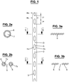
Fig. 1 shows a braided structure for producing an anchor of a first kind; -
Fig. 2a and 2b are an enlarged view of an example of a possible tubular cross-section, which the structure ofFig. 1 may have, when sectioned along line a-a and line b-b, respectively; -
Fig. 3a and 3b are an enlarged view of a flat cross-section, which the structure ofFig. 1 has in an example not being part of the invention, when sectioned along line a-a and line b-b, respectively; -
Fig. 4 shows an embodiment of an anchor of a first kind; -
Fig. 5 shows the anchor ofFig. 4 applied in a bone; -
Fig. 6 shows another embodiment of an anchor of a first kind; -
Fig. 7 shows a further embodiment of an anchor of a first kind; -
Fig. 8 shows a further embodiment of an anchor of a first kind; -
Fig. 9 shows a further embodiment of an anchor of a first kind; -
Fig. 10 shows a further embodiment of an anchor of a first kind; -
Fig. 11 shows a set with an instrument and an anchor of a first kind according toFig. 8 in a partly sectioned side view, wherein the instrument and the anchor are shown only in part; -
Fig. 12 shows the set ofFig. 11 in a partly sectioned front view; -
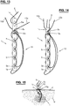
Fig. 13 shows a further embodiment of an anchor of a first kind; -
Fig. 14 shows a further embodiment of an anchor of a first kind; -
Fig. 15 shows the anchor ofFig. 13 applied in a bone; -
Fig. 16 shows a set with an instrument and an anchor of a first kind in a partly sectioned front view, wherein the instrument and the anchor are shown only in part; -
Fig. 17 shows a braided structure for producing an anchor of a second kind; -
Fig. 18 shows an embodiment of an anchor of a second kind; -
Fig. 19 shows a set with an instrument and an anchor of a second kind in a partly sectioned front view, wherein the instrument and the anchor are shown only in part; -
Fig. 20 shows schematically part of a drill for drilling a hole in a bone; -
Fig. 21 shows the set ofFig. 19 applied for the hole ofFig. 20 ; -
Fig. 22 shows a braided structure for producing an anchor of a third kind; -
Fig. 23 shows an embodiment of an anchor of a third kind; -
Fig. 24 shows a further embodiment of an anchor of a third kind; -
Fig. 25 shows a set with an instrument and an anchor of a third kind in a partly sectioned side view, wherein only part of the instrument and the anchor is shown; and -
Fig. 26 shows a braided structure for producing an anchor of a fourth kind. -
Fig. 1 shows a flexible slender structure, which comprises a plurality ofeyelets 5 passing therethrough. Thus, aneyelet 5 defines an opening which extends from one side of the structure to its other side. To form acollapsible member 1 for an anchor of a first kind shown inFig. 4-10 ,13-15 , a portion with a predetermined length is cut off from the structure ofFig. 1 . The latter is a textile which is braided such that, in an alternating fashion, it bifurcates at acentral portion 3 into two separatedbranch portions central portion 3 to form aneyelet 5. The length Lc of thecentral portions 3 and the length Le of theeyelets 5 may be the same or may vary. InFig. 1 eachcentral portion 3 is shown as having the same width Wc and eachbranch portion central portions 3 and/or the width We of thebranch portions - The braiding is done such that the
strands 6 form a tubular structure including tubularcentral portions 3 which bifurcate into twotubular branches eyelet 5. This kind of structure is apparent fromFig. 2a, 2b . Optionally, theinterior - Machines arranged for tubular braiding cause the yarn carriers to move in a circle. This results in a tubular structure having an interior, which may or may not include a core. Machines arranged for flat braiding cause the yarn carriers to move on a line back and forth. This results in a flat structure without an interior.
-
Fig. 4 shows an example of an anchor comprising acollapsible member 1 having afirst end 1a, a second 1b as well as a plurality ofeyelets 5 arranged therebetween and afilament 10 passed through at least some of theeyelets 5. Thecollapsible member 1 may be produced e.g. by cutting off a portion from the structure ofFig. 1 . Here, thefilament 10 is a flexible member separate from thecollapsible member 1 and may have a suture- or lace-like structure. - The
filament 10 is interconnected with thecollapsible member 1 such that when pulling thereon themember 1 collapses to form a folded structure having an increased lateral extension (seeFig. 5 ). In the following, the side of themember 1 visible inFig. 4 is designated as the front side, while the non-visible side is the rear side. Here, thefilament 10 is folded in the middle to form aloop portion 10c arranged at the front side of themember 10. Both ends 10a and 10b of thefilament 10 are passed from the rear side of themember 1 through thefirst eyelet 5a arranged at theend 1a and through theloop portion 10c, so that a knot is formed, and are directed through thelast eyelet 5b arranged at theend 1b. Subsequently, the twoends eyelets 5 from one side of themember 1 to the other side. Finally, theends first eyelet 5a. -
Fig. 5 shows an example of ananchor member 1 thereinto by means of a suitable instrument and pulls on theends filament 10, so that themember 1 adopts a collapsed structure, which is firmly anchored in the bone B. -
Fig. 6 shows a variant of the anchor ofFig. 4 , in which theends filament 10 are guided from thelast eyelet 5b to thefirst eyelet 5a not in parallel, but in a crossed fashion. Thus, theends eyelet -
Fig. 7 shows a variant of the anchor, in which thefirst end 10a of thefilament 10 is directed through thefirst eyelet 5a of themember 1 and knotted together at aposition 10d. The other (free)end 10b is directed through thelast eyelet 5b and is led subsequently in an alternating manner through theeyelets 5 from one side of themember 1 to the other side. In this variant, theanchor end 10b utilizable for fixation. -
Fig. 8 shows another variant of the anchor, in which thefilament 10 is directed through theeyelets 5 alternatingly from one side of themember 1 to its other side. In addition, thefilament 10 is fixed in the area of the middle of themember 1, so that it cannot be shifted as a whole relative to themember 1. For this purpose, thefilament 10 is guided e.g. through theeyelet 5c to form aknot 10e. It is conceivable to provide for asecond filament 8 which is guided through theeyelets 5 in parallel with thefilament 10 as shown inFig. 9 . Thesecond filament 8 is attached in the middle of themember 1, for instance it is knotted to a branch portion of theeyelet 5c in a similar way as thefilament 10. -
Fig. 10 shows a variant of the anchor ofFig. 9 , in which thefirst filament 10 and thesecond filament 8 are guided through the eyelets not in parallel, but in a crossed manner. Thus, thefilaments second filaments eyelet 5c to form aknot 8e and aknot 10e, respectively. -
Fig. 11 and 12 show part of aninstrument 20 suitable to apply an anchor at a specific location in the body of a patient. Theinstrument 20 comprises acannula 21 defining a tube which is open at the distal end and which serves for receiving astopper element 22, aninserter element 23 and an anchor, e.g. theanchor Fig. 8 . The distal end of thecannula 21 may have a tapered or straight form. Theelements cannula 21 that they are movable relative to each other. Thestopper element 22 has at its distal end astopper face 22a and includes a boring 22b through which theinserter element 23 and theends filament 10 extend. Theinserter element 23, which has here the form of a rod, comprises anend 23a to act on theanchor member 1 is arranged in a U-shaped form along theend 23a of theinserter element 23 - In use, the
elements anchor member 1 and theend 23a emerge out of thecannula 21 and into the cavity, where theanchor 1 is to be applied. Subsequently, theinserter element 23 is retracted, whereas thestopper element 22 remains at the same position, which is on the cortex, in case the cavity is a hole in bone. Thereby, theanchor stopper face 22a to ensure that it remains in the cavity. After first pulling theends member 1, thewhole instrument 20 is finally removed. -
Fig. 13 shows another variant of the anchor. Thefilament 10 is folded in the middle to form aloop portion 10c arranged at the front side of themember 1. Both ends 10a and 10b of thefilament 10 are passed from the rear side of themember 1 through thesecond eyelet 5d arranged at theend 1a and through theloop portion 10c and are directed through thelast eyelet 5b arranged at theend 1b, so that theends member 1. Subsequently, the twoends eyelets 5 from one side of themember 1 to the other side, such that in each case theends member 1. Finally, theends second eyelet 5d at theend 1a. The anchor comprises a second filament 9, which is guided through thefirst eyelet 5a at theend 1a, so that it can be shifted as a whole relative to themember 1. In order to facilitate the usage of the anchor, the twofilaments 9 and 10 may have for instance different colors. - In use, the surgeon pushes the
member 1 by means of a suitable instrument into a hole H, which is drilled e.g. in the bone of a patient, and pulls on theends filament 10, so that themember 1 adopts a collapsed structure, seeFig. 15 . To firmly seat the anchor in the bone B, theends knot 10g. The second filament 9, whose ends are arranged outside of the hole H and which is shiftable relative to themember 1, can be used for fixation of another part, such as a ligament, tendon or bone. - The location, where the second filament 9 is guided through an eyelet, the location with the
loop portion 10c and the location, where thefree ends Fig. 13 at thefirst eyelet 5a and thesecond eyelet 5b, respectively. These locations may be chosen at other eyelets.Fig. 14 shows an example, where said three locations are arranged at thefirst eyelet 5a. -
Fig. 16 shows part of aninstrument 30 suitable to introduce an anchor in particular in soft tissue of a patient. Theinstrument 30 may also be used to apply an anchor to hard tissue. It comprises acannula 31 defining a tube which is open at the distal end and which serves for receiving apusher element 32 and an anchor, e.g. theanchor Fig. 14 with or without the second filament 9. Thepusher element 32 includes agroove 32a, which extends along its longitudinal axis and in which theends filament 10 are received. In case, the anchor includes a second filament, e.g. filament 9 inFig. 14 , thegroove 32a is configured such that the ends of bothfilaments 9 and 10 can be accommodated therein. - It is conceivable to provide for more than one groove extending along the axis of the pushing
element 32 for receiving the ends of the filament 10 (and of the filament 9 if present). For instance two grooves may be provided, which may be arranged at opposed sides of thepusher element 32, wherein thefirst end 10a of thefilament 10 is received in the first groove and thesecond end 10a of thefilament 10 10 is received in the second groove. If a filament 9 is present, one of its ends may be received in the first groove and its other end in the second groove. - Furthermore, other types of recesses are conceivable for receiving the ends of a filament, e.g. the
pusher element 32 may have a bore extending along its longitudinal axis. - In use, the end of the
instrument 30 is introduced into the hole, which is formed e.g. in soft tissue, thepusher element 32 is moved forward, so that the anchor is freed out of the interior of thecannula 31. After removing theinstrument 30, pulling on theends member 1 to collapse. -
Fig. 17 shows another example of a flexible slender structure which can be used to form an anchor of a second kind. The structure comprises first parts P1 and second parts P2, which are arranged in an alternating manner along the structure. Each first part P1 comprises a plurality ofeyelets 5 passing through the structure, whereas each second part P2 is free ofeyelets 5. The second part P2 is similar to acentral portion 3 of the first part P1, however with a longer length and, typically, with a smaller width. The number of strands for braiding the second parts P2 may be the same or smaller than the number of strands for braiding the first parts P1. The number ofeyelets 5 and their dimension may be chosen with regard to the specific needs of the anchor. The length of a part P2 is greater than that of a part P1, so that it can be passed througheyelets 5 of the part P1 as described further below. - The structure with the parts P1, P2 is braided such that its strands bifurcate and converge to form the parts P2 and the parts P1 with the
eyelets 5 and thecentral portions 3. Similar as in the example ofFig. 2 , the parts P1 and P2 have tubular braids with or without a core. - The structure of
Fig. 17 may be cut in each case in the middle of each second part P2 (see location ps inFig. 17 ) resulting in anchors with a symmetrical form (seeFig. 18 ). - The anchor shown in
Fig. 18 comprises acollapsible member 1 formed by a first part P1 of the structure ofFig. 17 and twofilaments filaments member 1. Themember 1 has aneyelet 5c in the middle between both ends 1a and 1b, which is left free and which may be used to cooperate with theend 43a of an inserter element 43 (seeFig. 19 ). Theend 12b of thefilament 12 is guided through aneyelet 5d adjacent to theeyelet 5c in the middle and then through the following eyelet(s) 5 from one side to the other side of themember 1 up to theeyelet 5a at theend 1a of themember 1. Thesecond filament 13 is arranged in a symmetrical way to thefirst filament 12 by guiding itsend 13b through aneyelet 5e adjacent to theeyelet 5c in the middle and then through the following eyelet(s) 5 from one side to the other side of themember 1 up to theeyelet 5b at theend 1b of themember 1. - In use, pulling on the
ends filaments member 1 to collapse. -
Fig. 19 shows part of aninstrument 40 suitable to introduce an anchor in particular in hard tissue, such as bone. Theinstrument 40 may also be used to apply an anchor to soft tissue. It comprises acannula 41 defining a tube which is open at the distal end and which serves for receiving astopper element 42, aninserter element 43 and an anchor, e.g. theanchor Fig. 18 . Theelements cannula 41 that they are movable relative to each other. Thestopper element 42 has at its distal end astopper face 42a and includes a boring 42b through which theinserter element 43 and theends filaments inserter element 43, which has here the form of a rod, comprises anend 43a. Theanchor cannula 41, so that theend 43a of theinserter element 43 can pass through theeyelet 5c in the middle of themember 1. - In use, the surgeon drills with a suitable drill 48 a hole H e.g. into the bone B of a patient as shown in
Fig. 20 . Thecannula 41 of theinstrument 40 may be used as a guide for thedrill 48 so that the latter moves into the bone B in a defined direction. After removal of thedrill 48, theanchor elements cannula 41 and moved forward until thestopper face 42a of thestopper element 42 abuts on the cortex C. Thereby, theanchor end 43a of theinserter element 43 enters into the hole H, seeFig. 21 . Subsequently, theinserter element 43 is retracted, whereby thestopper face 42a ensures that theanchor ends 12a, 12b to collapse themember 1, thewhole instrument 40 is removed. -
Fig. 22 shows another example of a flexible slender structure which can be used to form an anchor of a third kind. The structure comprises first parts P1' and second parts P2', which are arranged in an alternating manner along the structure. Each first part P1' comprises a plurality ofeyelets 5 passing through the structure, whereas each second part P2' includes twobranch portions 4a', 4b'. The second part P2' is similar to thebranch portions eyelets 5 of the first part P1' as described further below. - The structure with the parts P1', P2' is braided such that its strands bifurcate and converge to form the parts P2' and the parts P1' with the
eyelets 5 and thecentral portions 3. Similar as in the example ofFig. 2 , the parts P1' and P2' have tubular braids with or without a core. - The structure of
Fig. 22 may be cut in each case at one end of the first part P1' (see location pa inFig. 22 ) resulting in anchors with an asymmetrical form (seeFig. 23 and 24 ) or in the middle of each second part P2' (see location ps inFig. 22 ) resulting in anchors with a symmetrical form (seeFig. 25 ). After cutting, thebranch portions 4a', 4b' build free ends for handling. If need be,individual branch portions 4a', 4b' may be cut further to adjust the length. In order to facilitate their distinction, it is conceivable to use strands of different colors for braiding the structure, so that abranch portion 4a' is different in color from abranch portion 4b'. This is illustrated inFig. 22 , in which abranch portions 4b' is displayed hatched and abranch portion 4a' is dotted. The first part P1' is hatched and dotted, since it includes strands of either color. - The anchor shown in
Fig. 23 comprises acollapsible member 1 formed by the first part P1' of the structure ofFig. 22 and twofilaments branch portions 4a', 4b' of the second part P2. As the anchor is braided as a whole, thefilaments member 1. Thefilaments last eyelet 5b arranged at theend 1b of themember 1 and then in a parallel manner through the followingeyelets 5 from one side to the other side of themember 1 up to thefirst eyelet 5a at theend 1a of themember 1. In use, pulling on theends filaments member 1 to collapse. - The
filaments member 1.Fig. 24 shows one example, wherein thefilaments member 1 through an eyelet as inFig. 23 , but from opposite sides. -
Fig. 25 shows another example of an anchor received in theinstrument 40. The anchor comprises acollapsible member 1 formed by the first part P1' of the structure ofFig. 22 and four filaments 16-19, two per side, formed by second parts P2'. As the anchor is braided as a whole, the filaments 16-19 are made integral with themember 1. Themember 1 has aneyelet 5c in the middle between both ends 1a and 1b, which is left free and which may be used to cooperate with theend 43a of theinserter element 43. Theend 16b of thefilament 16 is guided through aneyelet 5d adjacent to theeyelet 5c in the middle and then through the following eyelet(s) 5 from one side to the other side of themember 1 up to theeyelet 5a at theend 1a of themember 1. Thesecond filament 17 is arranged in a symmetrical way to thefirst filament 16 by guiding itsend 17b through aneyelet 5e adjacent to theeyelet 5c in the middle and then through the following eyelet(s) 5 from one side to the other side of themember 1 up to theeyelet 5b at theend 1b of themember 1. The other twofilaments eyelets 5 of themember 1. As indicated inFig. 25 the color of thefilaments filaments - The
anchor 1, 16-19 may be applied in the body of a patient by means of theinstrument 40 in an analogous manner as explained above in connection withFig. 20 and 21 . After first pulling thefilaments member 1, theinstrument 40 can be removed. Thefilaments -
Fig. 26 shows another example of a flexible slender structure which can be used to form an anchor of a fourth kind, which includes a collapsible member with four filaments made integral therewith (instead of two filaments as for anchor of the third kind). - The structure of
Fig. 26 comprises first parts P1" and second parts P2", which are arranged in an alternating manner along the structure. Each first part P1" comprises a plurality ofeyelets 5 passing through the structure, whereas each second part P2" includes fourbranch portions 4a', 4a", 4b', 4b". The length of a second part P2" is greater than that of a first part P1", so that it can be passed througheyelets 5 of the first part P1". - The structure with the parts P1", P2" is braided such that its strands bifurcate and converge to form the parts P2" and the parts P1" with the
eyelets 5 and thecentral portions 3. Similar as in the example ofFig. 2 , the parts P1" and P2" have tubular braids with or without a core. - The structure of
Fig. 26 may be cut in each case at one end of the first part P1" (see location pa inFig. 26 ) resulting in anchors with an asymmetrical form or in the middle of each second part P2" (see location ps inFig. 26 ) resulting in anchors with a symmetrical form. After cutting, thebranch portions 4a', 4a", 4b', 4b" build free ends of filaments. If need be,individual branch portions 4a', 4a", 4b', 4b" may be cut further to adjust the length. Some of thebranch portions 4a', 4a", 4b', 4b" may be then guided througheyelets 5 of the first part P1" similar as thefilaments 12 to 17 in the anchor ofFig. 18 ,23 to 25 and some of thebranch portions 4a', 4a", 4b', 4b" may remain unconnected with theeyelets 5 like thefilaments Fig. 25 . - In order to facilitate the distinction of the four filaments of the anchor, it is conceivable to braid the structure such that the color and/or pattern is different for each
portion - As explained above the structures of
Fig. 1 ,17 ,22 and26 are made as a fabric in form of a braid. A braid is a structure formed by interlacing strands of flexible material by being placed diagonally to the product axis. Typically, each strand passes alternately over and under each other always in opposite direction. The braid may be two dimensional or three dimensional. In the latter case, a strand runs through the braid in all three directions. All or at least some of the strands of the structures ofFig. 1 ,17 ,22 and26 extend through the whole structure. In order to vary the thickness, some strands may not run through the whole structure ofFig. 1 ,17 and22 , so that the number of strands may be different at different cross-sections of the structure. - Braiding leads to a structure having a high strength. The strands are interlaced such that they do not get separated from each other when for instance a force acts on the location of the bifurcation or convergence of an
eyelet 5. The location of bifurcation/convergence can be reinforced e.g. if necessary with an additional thermal in line process after the braiding. - The structures of
Fig. 1 ,17 ,22 and26 may be fabricated by means of a braiding machine comprising bobbin carriers which carry the bobbins with the rewound raw material, which forms the strands, as called here. In the braiding operation, the bobbins are advanced along specific tracks of travel, see e.g.EP 2 492 385 A2 . - Generally, braiding leads to a different structure then e.g. weaving, where the strands are interlaced at right angles to form the textile, or knitting, where multiple loops of the strands are created.
- In order to be suitable for implanting in the human body, biocompatible material is used for the anchor. A strand to be used for braiding includes a monofilament or a multifilament of the same or different type of materials. Examples of suitable materials are:
- chemical fibers, e.g. ultra-high-molecular-weight polyethylene, polyester, polypropylene, polyamide
- natural fibers, e.g. silk, flax, hemp
- metallic fibers, e.g. nickel titanium (Nitinol)
- biodegradable fibers, e.g. polylactic acid (PLA), polyglycolic acid (PGA).
- It is also possible to combine different types of material to produce the structures of
Fig. 1 ,17 ,22 and26 , e.g. polyester with polyamide, polyester with hemp, flax with silk, etc. - A fiber may be formed as a single yarn or as multiple yarns, which are twisted together or are combined without twist.
- Individual components of the structure of
Fig. 1 ,17 ,22 and26 , i.e. fiber, yarn, strand, core, etc., or the whole structure may be provided with an additional layer obtained e.g. by impregnating a substance or by plasma deposition. - The anchors described herein have diverse medical applications. They may serve for any type of tissue fastening or securement application, in particular any hard and/or soft tissue-to-tissue securement, tissue-to-device securement, and any other tissue securement application. The anchors may be used to establish a strong point of connection for securing elements relative to a tissue location in a patient or to secure two or more tissue portions together.
- In particular, the anchors described herein may be used to fix for instance a tendon to a bone, a ligament to a bone, a bone to a bone, a tendon to a tendon, a tear in a cartilage-like structure, etc. The anchors may be used e.g. in the shoulder, in particular for restoration of the rotator cuff, for example when reattaching soft tissue to bone. Other areas of application are in the knee, in particular for meniscal repair, in the hip, in particular for acetabular labral repair, in the treatment of syndesmosis injuries and in osteosynthesis, in particular for fixation of plates, or of a bone with another bone. In case of poor bone quality, a screw drilled therein may not hold anymore, whereas an anchor described herein may ensure still a reliable fixation.
- From the preceding description, many modifications are available to the skilled person without departing from the scope of the invention, which is defined in the claims.
- For instance it is conceivable to braid a collapsible member together with any filament attached thereon in an individual manner, instead of producing an endless structure as shown in
Fig. 1 ,17 ,22 ,26 which are cut apart.
Claims (15)
- Implantable textile anchor, comprising:a collapsible member (1) including a first end (1a), a second end (1b) and a plurality of eyelets (5) arranged between the first end and the second end, andat least one filament, which is guided through eyelets of the collapsible member so that by pulling on the at least one filament the collapsible member collapses to a form with an increased lateral extension,characterized in that the collapsible member is braided to form alternatingly tubular central portions (3) and bifurcating and converging tubular branch portions (4a, 4b), which define the eyelets, wherein
the at least one filament (8, 10) is knotted to an eyelet (5a, 5c, 5d) and/or
wherein the at least one filament (12, 14, 16) and at least a second filament (13, 15, 17-19) are made integral with the collapsible member (1) by braiding the collapsible member and the filaments (12-19) together. - The anchor according to claim 1, wherein the at least one filament (10) is knotted (10c, 10d) to a first eyelet (5a) arranged at the first end (1a) of the collapsible member (1), guided through a second eyelet (5) arranged at the second end (1b) of the collapsible member (1) and through eyelets arranged between the first and second eyelets.
- The anchor according to any one of the preceding claims, wherein the at least one filament (8, 10) is separate from the collapsible member (1) and guided through eyelets (5) such that both ends (8a, 8b, 10a, 10b) of the filament (8, 10) are accessible for pulling thereon.
- The anchor according to any one of the preceding claims, comprising another filament (9), which is separate from the collapsible member (1) and interconnected therewith such that it is shiftable as a whole relative to the collapsible member.
- The anchor according to any one of the preceding claims, wherein one (12, 14, 16, 18) of the two braided filaments is attached to the first end (1a) of the collapsible member (1) and the other one (13, 15, 17, 19) of the two braided filaments is attached to the first end (1a) or the second end (1b) of the collapsible member.
- The anchor according to any one of the preceding claims, wherein one (12, 16) of the two braided filaments is guided through eyelets (5, 5a, 5d) arranged at the first end (1a) and the other one (13, 17) of the two braided filaments is guided through eyelets (5, 5b, 5e) arranged at the second end (1b) of the collapsible member (1).
- The anchor according to claim 6, wherein, for cooperating with an end (43a) of an inserter element (43), an eyelet (5c) arranged between the first and second end (1a, 1b) of the collapsible member (1) is left free from guiding the two braided filaments (12, 13, 16, 17) therethrough.
- The anchor according to any one of the preceding claims, comprising at least four filaments (16-19) made integral with the collapsible member (1) by braiding the member and filaments together.
- The anchor according to any one of the preceding claims, wherein the interior of the central and branch portions (3, 4a, 4b) include a core.
- A set comprising at least one anchor according to any one of the preceding claims and an instrument (20, 30, 40) for implanting the anchor, the instrument comprising a cannula (21, 31, 41) for receiving the anchor as well as at least one element (22, 23, 32, 42, 43), which is movable relative to the cannula for acting on the anchor.
- The set according to claim 10, wherein the element (22, 32, 42) comprises at least one recess (22b, 32a, 42b) extending along the element for receiving part (10a, 10b, 12b-17b) of the at least one filament (10-19).
- The set according to claim 10 or 11, wherein the element is an inserter element (23, 43), whose end (23a, 43a) cooperates with the anchor and which extends through a boring (22b, 42b) in a stopper element (22, 42), the inserter element and the stopper element being arranged movably relative to each other.
- A method for producing an implantable textile anchor comprising
a collapsible member (1) including a first end (1a), a second end (1b) and a plurality of eyelets (5) arranged between the first end and the second end, the collapsible member being braided to form alternatingly tubular central portions (3) and bifurcating and converging tubular branch portions (4a, 4b), which define the eyelets, and
at least one filament, which is guided through eyelets of the collapsible member so that by pulling on the at least one filament the collapsible member collapses to a form with an increased lateral extension, wherein in the method a continuous structure comprising the eyelets (5) is braided and pieces are cut off providing the collapsible member (1). - The method of claim 13, wherein the continuous structure has alternatingly a first portion (P1, P1', P1"), which comprises the eyelets (5) and which defines the collapsible member (1), and a second portion (P2, P2', P2"), which is free of eyelets and which define the one or more filaments (12-19) made integral with the collapsible member.
- The method of claim 14, wherein pieces including first and second portions (P1, P1', P1", P2, P2', P2") are cut off from the continuous structure in a symmetrical way such that a second portion (P2, P2', P2") is arranged at each end of the first portion (P1, P1', P1") of a piece or in an asymmetrical way such that a second portion (P2, P2', P2") is arranged only at one end of the first portion (P1, P1', P1") of a piece.
Applications Claiming Priority (2)
| Application Number | Priority Date | Filing Date | Title |
|---|---|---|---|
| EP16154504 | 2016-02-05 | ||
| PCT/EP2017/051147 WO2017133903A2 (en) | 2016-02-05 | 2017-01-20 | Implantable textile anchor |
Publications (2)
| Publication Number | Publication Date |
|---|---|
| EP3410951A2 EP3410951A2 (en) | 2018-12-12 |
| EP3410951B1 true EP3410951B1 (en) | 2021-03-24 |
Family
ID=55310734
Family Applications (1)
| Application Number | Title | Priority Date | Filing Date |
|---|---|---|---|
| EP17702787.7A Active EP3410951B1 (en) | 2016-02-05 | 2017-01-20 | Implantable textile anchor |
Country Status (5)
| Country | Link |
|---|---|
| US (1) | US11154292B2 (en) |
| EP (1) | EP3410951B1 (en) |
| CN (1) | CN108712885B (en) |
| RU (1) | RU2732436C2 (en) |
| WO (1) | WO2017133903A2 (en) |
Cited By (1)
| Publication number | Priority date | Publication date | Assignee | Title |
|---|---|---|---|---|
| WO2025083240A1 (en) * | 2023-10-20 | 2025-04-24 | 41Medical Ag | Ligament clamping device |
Families Citing this family (9)
| Publication number | Priority date | Publication date | Assignee | Title |
|---|---|---|---|---|
| WO2019170769A1 (en) | 2018-03-06 | 2019-09-12 | Dsm Ip Assets B.V. | Osteoconductive fibers, medical implant comprising such osteoconductive fibers, and methods of making |
| CN114469215B (en) * | 2020-11-13 | 2025-06-13 | 纳通生物科技(北京)有限公司 | A double hollow tube braided full suture anchor |
| WO2023039494A1 (en) * | 2021-09-09 | 2023-03-16 | Responsive Arthroscopy, LLC | All-suture anchor |
| EP4493076A4 (en) * | 2022-03-14 | 2026-02-18 | Endofix Medical Tech Inc | SYSTEM FOR FIXING SOFT TISSUE |
| US12527566B2 (en) | 2022-03-14 | 2026-01-20 | Endofix Medical Technologies, Inc. | Soft tissue fixation system |
| US12458340B2 (en) * | 2022-04-24 | 2025-11-04 | LMD Innovations, LLC | Tapetak and methods of anchoring soft tissue to bone |
| CN115341327B (en) * | 2022-08-18 | 2023-10-24 | 广州市实尚实业有限公司 | Ribbon loom control method, device, equipment and medium for smooth alternate type belt buckle |
| US20250366843A1 (en) * | 2024-05-28 | 2025-12-04 | Robert Trent McKay | Bioinductive collagen anchor for tissue repair |
| WO2026115444A1 (en) * | 2024-11-26 | 2026-06-04 | Arthrex, Inc. | Suture apparatus and automated manufacturing process |
Family Cites Families (17)
| Publication number | Priority date | Publication date | Assignee | Title |
|---|---|---|---|---|
| RU2116802C1 (en) | 1994-08-09 | 1998-08-10 | Московский областной научно-исследовательский клинический институт | Device for washing abdominal cavity |
| US7905903B2 (en) | 2006-02-03 | 2011-03-15 | Biomet Sports Medicine, Llc | Method for tissue fixation |
| US8361113B2 (en) * | 2006-02-03 | 2013-01-29 | Biomet Sports Medicine, Llc | Method and apparatus for coupling soft tissue to a bone |
| US7601165B2 (en) | 2006-09-29 | 2009-10-13 | Biomet Sports Medicine, Llc | Method and apparatus for forming a self-locking adjustable suture loop |
| US7749250B2 (en) | 2006-02-03 | 2010-07-06 | Biomet Sports Medicine, Llc | Soft tissue repair assembly and associated method |
| US7857830B2 (en) | 2006-02-03 | 2010-12-28 | Biomet Sports Medicine, Llc | Soft tissue repair and conduit device |
| US7608098B1 (en) | 2004-11-09 | 2009-10-27 | Biomet Sports Medicine, Llc | Bone fixation device |
| US8652172B2 (en) * | 2006-02-03 | 2014-02-18 | Biomet Sports Medicine, Llc | Flexible anchors for tissue fixation |
| US7771455B2 (en) * | 2007-08-31 | 2010-08-10 | Ken Christopher G M | Closure medical device |
| JP5763173B2 (en) * | 2010-04-27 | 2015-08-12 | ジンテス ゲゼルシャフト ミット ベシュレンクテル ハフツング | Anchor assembly with expandable anchor |
| US8795334B2 (en) * | 2011-01-28 | 2014-08-05 | Smith & Nephew, Inc. | Tissue repair |
| US20130018416A1 (en) * | 2011-04-15 | 2013-01-17 | Linvatec Corporation | Soft suture anchor made of braided or monofilament suture |
| GB2509679B (en) * | 2011-11-14 | 2018-09-05 | Arthrocare Corp | Tissue repair assembly |
| US9445803B2 (en) | 2011-11-23 | 2016-09-20 | Howmedica Osteonics Corp. | Filamentary suture anchor |
| US10448942B2 (en) * | 2013-02-26 | 2019-10-22 | Smith & Nephew, Inc. | Flexible deformable suture anchor |
| US9610077B2 (en) | 2013-08-08 | 2017-04-04 | EverestMedica LLC | Round-flat-round surgical braids |
| WO2015021439A1 (en) | 2013-08-08 | 2015-02-12 | Everestmedical, Llc | Surgical braids |
-
2017
- 2017-01-20 US US16/075,875 patent/US11154292B2/en active Active
- 2017-01-20 EP EP17702787.7A patent/EP3410951B1/en active Active
- 2017-01-20 CN CN201780015482.XA patent/CN108712885B/en active Active
- 2017-01-20 RU RU2018131572A patent/RU2732436C2/en active
- 2017-01-20 WO PCT/EP2017/051147 patent/WO2017133903A2/en not_active Ceased
Non-Patent Citations (1)
| Title |
|---|
| None * |
Cited By (1)
| Publication number | Priority date | Publication date | Assignee | Title |
|---|---|---|---|---|
| WO2025083240A1 (en) * | 2023-10-20 | 2025-04-24 | 41Medical Ag | Ligament clamping device |
Also Published As
| Publication number | Publication date |
|---|---|
| US20190038277A1 (en) | 2019-02-07 |
| US11154292B2 (en) | 2021-10-26 |
| BR112018015907A2 (en) | 2018-12-26 |
| RU2018131572A (en) | 2020-03-05 |
| WO2017133903A2 (en) | 2017-08-10 |
| CN108712885A (en) | 2018-10-26 |
| RU2732436C2 (en) | 2020-09-16 |
| WO2017133903A3 (en) | 2017-09-21 |
| RU2018131572A3 (en) | 2020-04-13 |
| EP3410951A2 (en) | 2018-12-12 |
| CN108712885B (en) | 2021-04-30 |
Similar Documents
| Publication | Publication Date | Title |
|---|---|---|
| US11154292B2 (en) | Implantable textile anchor | |
| EP2774545B1 (en) | Knotless filamentary fixation devices | |
| CN102202609A (en) | Tubular implantable wire | |
| JP6792929B2 (en) | Suture anchor with suture filament and suture tape | |
| CN103385741B (en) | Use the systems, devices and methods of snare component and soft holdfast fixing organization | |
| JP7488277B2 (en) | Surgical fixation systems and related methods - Patents.com | |
| CN113924060B (en) | Methods and apparatus for tissue graft fixation | |
| RU2010122500A (en) | SURGICAL SEWING MATERIAL CONSISTING OF WOVEN THREADS | |
| EP4084735B1 (en) | Knotless constructs for tissue repairs and reconstructions | |
| CN104706393A (en) | Implant having filament limbs of an adjustable loop disposed in a shuttle suture | |
| US20150066079A1 (en) | Suture tape with exterior suture strands | |
| WO2009109778A2 (en) | Implantable prosthetic cord | |
| CN104665887A (en) | Implant having adjustable filament coils | |
| EP4096530B1 (en) | Knotless soft tissue implant systems | |
| KR101849682B1 (en) | Flat type sleeve anchor | |
| US20180185135A1 (en) | Implantable holding device | |
| EP3925544A1 (en) | Suture device | |
| US20250160813A1 (en) | Soft anchors for anatomical fixation, and related systems and methods | |
| BR112018015907B1 (en) | IMPLANTABLE TEXTILE ANCHOR, ASSEMBLY COMPRISING AT LEAST ONE ANCHOR AND METHOD FOR PRODUCING AN IMPLANTABLE TEXTILE ANCHOR | |
| US20260102157A1 (en) | Soft suture construct with bifurcated sheath |
Legal Events
| Date | Code | Title | Description |
|---|---|---|---|
| STAA | Information on the status of an ep patent application or granted ep patent |
Free format text: STATUS: UNKNOWN |
|
| STAA | Information on the status of an ep patent application or granted ep patent |
Free format text: STATUS: THE INTERNATIONAL PUBLICATION HAS BEEN MADE |
|
| PUAI | Public reference made under article 153(3) epc to a published international application that has entered the european phase |
Free format text: ORIGINAL CODE: 0009012 |
|
| STAA | Information on the status of an ep patent application or granted ep patent |
Free format text: STATUS: REQUEST FOR EXAMINATION WAS MADE |
|
| 17P | Request for examination filed |
Effective date: 20180719 |
|
| AK | Designated contracting states |
Kind code of ref document: A2 Designated state(s): AL AT BE BG CH CY CZ DE DK EE ES FI FR GB GR HR HU IE IS IT LI LT LU LV MC MK MT NL NO PL PT RO RS SE SI SK SM TR |
|
| AX | Request for extension of the european patent |
Extension state: BA ME |
|
| DAV | Request for validation of the european patent (deleted) | ||
| DAX | Request for extension of the european patent (deleted) | ||
| STAA | Information on the status of an ep patent application or granted ep patent |
Free format text: STATUS: EXAMINATION IS IN PROGRESS |
|
| 17Q | First examination report despatched |
Effective date: 20191015 |
|
| GRAP | Despatch of communication of intention to grant a patent |
Free format text: ORIGINAL CODE: EPIDOSNIGR1 |
|
| STAA | Information on the status of an ep patent application or granted ep patent |
Free format text: STATUS: GRANT OF PATENT IS INTENDED |
|
| INTG | Intention to grant announced |
Effective date: 20200506 |
|
| GRAJ | Information related to disapproval of communication of intention to grant by the applicant or resumption of examination proceedings by the epo deleted |
Free format text: ORIGINAL CODE: EPIDOSDIGR1 |
|
| STAA | Information on the status of an ep patent application or granted ep patent |
Free format text: STATUS: EXAMINATION IS IN PROGRESS |
|
| GRAP | Despatch of communication of intention to grant a patent |
Free format text: ORIGINAL CODE: EPIDOSNIGR1 |
|
| STAA | Information on the status of an ep patent application or granted ep patent |
Free format text: STATUS: GRANT OF PATENT IS INTENDED |
|
| INTC | Intention to grant announced (deleted) | ||
| INTG | Intention to grant announced |
Effective date: 20201007 |
|
| GRAS | Grant fee paid |
Free format text: ORIGINAL CODE: EPIDOSNIGR3 |
|
| GRAA | (expected) grant |
Free format text: ORIGINAL CODE: 0009210 |
|
| STAA | Information on the status of an ep patent application or granted ep patent |
Free format text: STATUS: THE PATENT HAS BEEN GRANTED |
|
| AK | Designated contracting states |
Kind code of ref document: B1 Designated state(s): AL AT BE BG CH CY CZ DE DK EE ES FI FR GB GR HR HU IE IS IT LI LT LU LV MC MK MT NL NO PL PT RO RS SE SI SK SM TR |
|
| REG | Reference to a national code |
Ref country code: GB Ref legal event code: FG4D |
|
| REG | Reference to a national code |
Ref country code: CH Ref legal event code: EP |
|
| REG | Reference to a national code |
Ref country code: IE Ref legal event code: FG4D |
|
| REG | Reference to a national code |
Ref country code: AT Ref legal event code: REF Ref document number: 1373666 Country of ref document: AT Kind code of ref document: T Effective date: 20210415 Ref country code: DE Ref legal event code: R096 Ref document number: 602017035151 Country of ref document: DE |
|
| REG | Reference to a national code |
Ref country code: LT Ref legal event code: MG9D |
|
| PG25 | Lapsed in a contracting state [announced via postgrant information from national office to epo] |
Ref country code: BG Free format text: LAPSE BECAUSE OF FAILURE TO SUBMIT A TRANSLATION OF THE DESCRIPTION OR TO PAY THE FEE WITHIN THE PRESCRIBED TIME-LIMIT Effective date: 20210624 Ref country code: NO Free format text: LAPSE BECAUSE OF FAILURE TO SUBMIT A TRANSLATION OF THE DESCRIPTION OR TO PAY THE FEE WITHIN THE PRESCRIBED TIME-LIMIT Effective date: 20210624 Ref country code: FI Free format text: LAPSE BECAUSE OF FAILURE TO SUBMIT A TRANSLATION OF THE DESCRIPTION OR TO PAY THE FEE WITHIN THE PRESCRIBED TIME-LIMIT Effective date: 20210324 Ref country code: HR Free format text: LAPSE BECAUSE OF FAILURE TO SUBMIT A TRANSLATION OF THE DESCRIPTION OR TO PAY THE FEE WITHIN THE PRESCRIBED TIME-LIMIT Effective date: 20210324 Ref country code: GR Free format text: LAPSE BECAUSE OF FAILURE TO SUBMIT A TRANSLATION OF THE DESCRIPTION OR TO PAY THE FEE WITHIN THE PRESCRIBED TIME-LIMIT Effective date: 20210625 |
|
| PG25 | Lapsed in a contracting state [announced via postgrant information from national office to epo] |
Ref country code: RS Free format text: LAPSE BECAUSE OF FAILURE TO SUBMIT A TRANSLATION OF THE DESCRIPTION OR TO PAY THE FEE WITHIN THE PRESCRIBED TIME-LIMIT Effective date: 20210324 Ref country code: LV Free format text: LAPSE BECAUSE OF FAILURE TO SUBMIT A TRANSLATION OF THE DESCRIPTION OR TO PAY THE FEE WITHIN THE PRESCRIBED TIME-LIMIT Effective date: 20210324 Ref country code: SE Free format text: LAPSE BECAUSE OF FAILURE TO SUBMIT A TRANSLATION OF THE DESCRIPTION OR TO PAY THE FEE WITHIN THE PRESCRIBED TIME-LIMIT Effective date: 20210324 |
|
| REG | Reference to a national code |
Ref country code: NL Ref legal event code: MP Effective date: 20210324 |
|
| REG | Reference to a national code |
Ref country code: AT Ref legal event code: MK05 Ref document number: 1373666 Country of ref document: AT Kind code of ref document: T Effective date: 20210324 |
|
| PG25 | Lapsed in a contracting state [announced via postgrant information from national office to epo] |
Ref country code: NL Free format text: LAPSE BECAUSE OF FAILURE TO SUBMIT A TRANSLATION OF THE DESCRIPTION OR TO PAY THE FEE WITHIN THE PRESCRIBED TIME-LIMIT Effective date: 20210324 |
|
| PG25 | Lapsed in a contracting state [announced via postgrant information from national office to epo] |
Ref country code: CZ Free format text: LAPSE BECAUSE OF FAILURE TO SUBMIT A TRANSLATION OF THE DESCRIPTION OR TO PAY THE FEE WITHIN THE PRESCRIBED TIME-LIMIT Effective date: 20210324 Ref country code: EE Free format text: LAPSE BECAUSE OF FAILURE TO SUBMIT A TRANSLATION OF THE DESCRIPTION OR TO PAY THE FEE WITHIN THE PRESCRIBED TIME-LIMIT Effective date: 20210324 Ref country code: LT Free format text: LAPSE BECAUSE OF FAILURE TO SUBMIT A TRANSLATION OF THE DESCRIPTION OR TO PAY THE FEE WITHIN THE PRESCRIBED TIME-LIMIT Effective date: 20210324 Ref country code: SM Free format text: LAPSE BECAUSE OF FAILURE TO SUBMIT A TRANSLATION OF THE DESCRIPTION OR TO PAY THE FEE WITHIN THE PRESCRIBED TIME-LIMIT Effective date: 20210324 Ref country code: AT Free format text: LAPSE BECAUSE OF FAILURE TO SUBMIT A TRANSLATION OF THE DESCRIPTION OR TO PAY THE FEE WITHIN THE PRESCRIBED TIME-LIMIT Effective date: 20210324 |
|
| PG25 | Lapsed in a contracting state [announced via postgrant information from national office to epo] |
Ref country code: PL Free format text: LAPSE BECAUSE OF FAILURE TO SUBMIT A TRANSLATION OF THE DESCRIPTION OR TO PAY THE FEE WITHIN THE PRESCRIBED TIME-LIMIT Effective date: 20210324 Ref country code: PT Free format text: LAPSE BECAUSE OF FAILURE TO SUBMIT A TRANSLATION OF THE DESCRIPTION OR TO PAY THE FEE WITHIN THE PRESCRIBED TIME-LIMIT Effective date: 20210726 Ref country code: RO Free format text: LAPSE BECAUSE OF FAILURE TO SUBMIT A TRANSLATION OF THE DESCRIPTION OR TO PAY THE FEE WITHIN THE PRESCRIBED TIME-LIMIT Effective date: 20210324 Ref country code: SK Free format text: LAPSE BECAUSE OF FAILURE TO SUBMIT A TRANSLATION OF THE DESCRIPTION OR TO PAY THE FEE WITHIN THE PRESCRIBED TIME-LIMIT Effective date: 20210324 Ref country code: IS Free format text: LAPSE BECAUSE OF FAILURE TO SUBMIT A TRANSLATION OF THE DESCRIPTION OR TO PAY THE FEE WITHIN THE PRESCRIBED TIME-LIMIT Effective date: 20210724 |
|
| REG | Reference to a national code |
Ref country code: DE Ref legal event code: R097 Ref document number: 602017035151 Country of ref document: DE |
|
| PG25 | Lapsed in a contracting state [announced via postgrant information from national office to epo] |
Ref country code: ES Free format text: LAPSE BECAUSE OF FAILURE TO SUBMIT A TRANSLATION OF THE DESCRIPTION OR TO PAY THE FEE WITHIN THE PRESCRIBED TIME-LIMIT Effective date: 20210324 Ref country code: DK Free format text: LAPSE BECAUSE OF FAILURE TO SUBMIT A TRANSLATION OF THE DESCRIPTION OR TO PAY THE FEE WITHIN THE PRESCRIBED TIME-LIMIT Effective date: 20210324 Ref country code: AL Free format text: LAPSE BECAUSE OF FAILURE TO SUBMIT A TRANSLATION OF THE DESCRIPTION OR TO PAY THE FEE WITHIN THE PRESCRIBED TIME-LIMIT Effective date: 20210324 |
|
| PLBE | No opposition filed within time limit |
Free format text: ORIGINAL CODE: 0009261 |
|
| STAA | Information on the status of an ep patent application or granted ep patent |
Free format text: STATUS: NO OPPOSITION FILED WITHIN TIME LIMIT |
|
| PG25 | Lapsed in a contracting state [announced via postgrant information from national office to epo] |
Ref country code: SI Free format text: LAPSE BECAUSE OF FAILURE TO SUBMIT A TRANSLATION OF THE DESCRIPTION OR TO PAY THE FEE WITHIN THE PRESCRIBED TIME-LIMIT Effective date: 20210324 |
|
| 26N | No opposition filed |
Effective date: 20220104 |
|
| PG25 | Lapsed in a contracting state [announced via postgrant information from national office to epo] |
Ref country code: IS Free format text: LAPSE BECAUSE OF FAILURE TO SUBMIT A TRANSLATION OF THE DESCRIPTION OR TO PAY THE FEE WITHIN THE PRESCRIBED TIME-LIMIT Effective date: 20210724 |
|
| PG25 | Lapsed in a contracting state [announced via postgrant information from national office to epo] |
Ref country code: MC Free format text: LAPSE BECAUSE OF FAILURE TO SUBMIT A TRANSLATION OF THE DESCRIPTION OR TO PAY THE FEE WITHIN THE PRESCRIBED TIME-LIMIT Effective date: 20210324 |
|
| REG | Reference to a national code |
Ref country code: BE Ref legal event code: MM Effective date: 20220131 |
|
| PG25 | Lapsed in a contracting state [announced via postgrant information from national office to epo] |
Ref country code: LU Free format text: LAPSE BECAUSE OF NON-PAYMENT OF DUE FEES Effective date: 20220120 |
|
| PG25 | Lapsed in a contracting state [announced via postgrant information from national office to epo] |
Ref country code: BE Free format text: LAPSE BECAUSE OF NON-PAYMENT OF DUE FEES Effective date: 20220131 |
|
| PG25 | Lapsed in a contracting state [announced via postgrant information from national office to epo] |
Ref country code: IE Free format text: LAPSE BECAUSE OF NON-PAYMENT OF DUE FEES Effective date: 20220120 |
|
| P01 | Opt-out of the competence of the unified patent court (upc) registered |
Effective date: 20230505 |
|
| PG25 | Lapsed in a contracting state [announced via postgrant information from national office to epo] |
Ref country code: HU Free format text: LAPSE BECAUSE OF FAILURE TO SUBMIT A TRANSLATION OF THE DESCRIPTION OR TO PAY THE FEE WITHIN THE PRESCRIBED TIME-LIMIT; INVALID AB INITIO Effective date: 20170120 |
|
| PG25 | Lapsed in a contracting state [announced via postgrant information from national office to epo] |
Ref country code: MK Free format text: LAPSE BECAUSE OF FAILURE TO SUBMIT A TRANSLATION OF THE DESCRIPTION OR TO PAY THE FEE WITHIN THE PRESCRIBED TIME-LIMIT Effective date: 20210324 Ref country code: CY Free format text: LAPSE BECAUSE OF FAILURE TO SUBMIT A TRANSLATION OF THE DESCRIPTION OR TO PAY THE FEE WITHIN THE PRESCRIBED TIME-LIMIT Effective date: 20210324 |
|
| PG25 | Lapsed in a contracting state [announced via postgrant information from national office to epo] |
Ref country code: MT Free format text: LAPSE BECAUSE OF FAILURE TO SUBMIT A TRANSLATION OF THE DESCRIPTION OR TO PAY THE FEE WITHIN THE PRESCRIBED TIME-LIMIT Effective date: 20210324 |
|
| REG | Reference to a national code |
Ref country code: DE Ref legal event code: R081 Ref document number: 602017035151 Country of ref document: DE Owner name: 41MEDICAL AG, CH Free format text: FORMER OWNER: MEISTER & CIE AG HASLE-RUEEGSAU, HASLE-RUEEGSAU, CH |
|
| REG | Reference to a national code |
Ref country code: DE Ref legal event code: R082 Ref document number: 602017035151 Country of ref document: DE Representative=s name: KOELLNER, MALTE, DR., DE Ref country code: DE Ref legal event code: R082 Ref document number: 602017035151 Country of ref document: DE Representative=s name: KOELLNER, MALTE, DIPL.-PHYS. DR.RER.NAT., DE |
|
| PG25 | Lapsed in a contracting state [announced via postgrant information from national office to epo] |
Ref country code: TR Free format text: LAPSE BECAUSE OF FAILURE TO SUBMIT A TRANSLATION OF THE DESCRIPTION OR TO PAY THE FEE WITHIN THE PRESCRIBED TIME-LIMIT Effective date: 20210324 |
|
| REG | Reference to a national code |
Ref country code: CH Ref legal event code: U11 Free format text: ST27 STATUS EVENT CODE: U-0-0-U10-U11 (AS PROVIDED BY THE NATIONAL OFFICE) Effective date: 20260201 |
|
| PGFP | Annual fee paid to national office [announced via postgrant information from national office to epo] |
Ref country code: GB Payment date: 20260123 Year of fee payment: 10 |
|
| PGFP | Annual fee paid to national office [announced via postgrant information from national office to epo] |
Ref country code: DE Payment date: 20260121 Year of fee payment: 10 |
|
| PGFP | Annual fee paid to national office [announced via postgrant information from national office to epo] |
Ref country code: IT Payment date: 20260126 Year of fee payment: 10 |
|
| PGFP | Annual fee paid to national office [announced via postgrant information from national office to epo] |
Ref country code: FR Payment date: 20260123 Year of fee payment: 10 |
|
| PGFP | Annual fee paid to national office [announced via postgrant information from national office to epo] |
Ref country code: CH Payment date: 20260201 Year of fee payment: 10 |