EP3410832A1 - Electrical junction box - Google Patents
Electrical junction box Download PDFInfo
- Publication number
- EP3410832A1 EP3410832A1 EP18184722.9A EP18184722A EP3410832A1 EP 3410832 A1 EP3410832 A1 EP 3410832A1 EP 18184722 A EP18184722 A EP 18184722A EP 3410832 A1 EP3410832 A1 EP 3410832A1
- Authority
- EP
- European Patent Office
- Prior art keywords
- heat shield
- relay
- shield wall
- electrical component
- circuit board
- Prior art date
- Legal status (The legal status is an assumption and is not a legal conclusion. Google has not performed a legal analysis and makes no representation as to the accuracy of the status listed.)
- Granted
Links
- 238000005192 partition Methods 0.000 claims description 82
- 230000003014 reinforcing effect Effects 0.000 claims description 23
- 230000005494 condensation Effects 0.000 description 24
- 238000009833 condensation Methods 0.000 description 24
- 230000008014 freezing Effects 0.000 description 21
- 238000007710 freezing Methods 0.000 description 21
- 230000007423 decrease Effects 0.000 description 19
- 230000000694 effects Effects 0.000 description 9
- 230000007257 malfunction Effects 0.000 description 7
- 238000009423 ventilation Methods 0.000 description 7
- 239000007769 metal material Substances 0.000 description 4
- 239000000446 fuel Substances 0.000 description 3
- 230000017525 heat dissipation Effects 0.000 description 3
- 239000002184 metal Substances 0.000 description 3
- 229910052751 metal Inorganic materials 0.000 description 3
- 239000007858 starting material Substances 0.000 description 3
- 229920003002 synthetic resin Polymers 0.000 description 3
- 239000000057 synthetic resin Substances 0.000 description 3
- XEEYBQQBJWHFJM-UHFFFAOYSA-N Iron Chemical compound [Fe] XEEYBQQBJWHFJM-UHFFFAOYSA-N 0.000 description 2
- 230000005674 electromagnetic induction Effects 0.000 description 2
- 238000005516 engineering process Methods 0.000 description 2
- 238000004519 manufacturing process Methods 0.000 description 2
- 239000003990 capacitor Substances 0.000 description 1
- 230000007613 environmental effect Effects 0.000 description 1
- 230000037431 insertion Effects 0.000 description 1
- 238000003780 insertion Methods 0.000 description 1
- 229910052742 iron Inorganic materials 0.000 description 1
- 239000000696 magnetic material Substances 0.000 description 1
- 239000000463 material Substances 0.000 description 1
- 230000002093 peripheral effect Effects 0.000 description 1
- 229920005989 resin Polymers 0.000 description 1
- 239000011347 resin Substances 0.000 description 1
- 229920002994 synthetic fiber Polymers 0.000 description 1
- 238000004804 winding Methods 0.000 description 1
Images


Classifications
-
- H—ELECTRICITY
- H05—ELECTRIC TECHNIQUES NOT OTHERWISE PROVIDED FOR
- H05K—PRINTED CIRCUITS; CASINGS OR CONSTRUCTIONAL DETAILS OF ELECTRIC APPARATUS; MANUFACTURE OF ASSEMBLAGES OF ELECTRICAL COMPONENTS
- H05K7/00—Constructional details common to different types of electric apparatus
- H05K7/20—Modifications to facilitate cooling, ventilating, or heating
- H05K7/20845—Modifications to facilitate cooling, ventilating, or heating for automotive electronic casings
-
- B—PERFORMING OPERATIONS; TRANSPORTING
- B60—VEHICLES IN GENERAL
- B60R—VEHICLES, VEHICLE FITTINGS, OR VEHICLE PARTS, NOT OTHERWISE PROVIDED FOR
- B60R16/00—Electric or fluid circuits specially adapted for vehicles and not otherwise provided for; Arrangement of elements of electric or fluid circuits specially adapted for vehicles and not otherwise provided for
- B60R16/02—Electric or fluid circuits specially adapted for vehicles and not otherwise provided for; Arrangement of elements of electric or fluid circuits specially adapted for vehicles and not otherwise provided for electric constitutive elements
- B60R16/023—Electric or fluid circuits specially adapted for vehicles and not otherwise provided for; Arrangement of elements of electric or fluid circuits specially adapted for vehicles and not otherwise provided for electric constitutive elements for transmission of signals between vehicle parts or subsystems
- B60R16/0238—Electrical distribution centers
-
- H—ELECTRICITY
- H05—ELECTRIC TECHNIQUES NOT OTHERWISE PROVIDED FOR
- H05K—PRINTED CIRCUITS; CASINGS OR CONSTRUCTIONAL DETAILS OF ELECTRIC APPARATUS; MANUFACTURE OF ASSEMBLAGES OF ELECTRICAL COMPONENTS
- H05K7/00—Constructional details common to different types of electric apparatus
- H05K7/02—Arrangements of circuit components or wiring on supporting structure
- H05K7/026—Multiple connections subassemblies
-
- H—ELECTRICITY
- H05—ELECTRIC TECHNIQUES NOT OTHERWISE PROVIDED FOR
- H05K—PRINTED CIRCUITS; CASINGS OR CONSTRUCTIONAL DETAILS OF ELECTRIC APPARATUS; MANUFACTURE OF ASSEMBLAGES OF ELECTRICAL COMPONENTS
- H05K7/00—Constructional details common to different types of electric apparatus
- H05K7/20—Modifications to facilitate cooling, ventilating, or heating
- H05K7/2039—Modifications to facilitate cooling, ventilating, or heating characterised by the heat transfer by conduction from the heat generating element to a dissipating body
- H05K7/20518—Unevenly distributed heat load, e.g. different sectors at different temperatures, localised cooling, hot spots
Definitions
- the present invention relates to an electrical junction box.
- an electrical junction box is employed, for example, as a module that is configured to control distribution of a current that is supplied from a power source to various vehicle electrical components.
- the electrical junction box houses various electrical components such as a relay and a fuse in a casing thereof.
- Patent Document 1 discloses a known relay that is used in the electrical junction box having the above-described configuration.
- Patent Document 1 Japanese Unexamined Patent Publication No. 2010-108661
- the relay described in Patent Document 1 includes an electrical component case, a terminal portion housed in the electrical component case, a coil connected to the terminal portion, and a metal plate that is exposed to an inside and an outside of the electrical component case, in addition to the terminal portion.
- moisture in the electrical component case can be actively condensed on the metal plate by heat generated by the coil when an environmental temperature decreases. Accordingly, condensation on a contact of the terminal portion is less likely to occur, and thus poor conduction at the contact, which may be caused by frozen condensation, hardly occurs.
- Patent Document 1 is made to prevent the poor conduction, which may be caused by the freezing, at the contact of the relay itself.
- the technology in Patent Document 1 does not take influence of other electrical components housed in the electrical junction box than the relay into consideration. Since the electrical junction box houses other various electrical components than the relay, influence of heat generated on such other electrical components, or influence of varied timing of supply/non-supply of the current depending on the kinds of electrical component, may cause the relay to easily have the problem of the poor conduction, which is caused by the freezing, at the contact.
- An object of the present invention is to prevent a malfunction of a start electrical component.
- the electrical junction box includes a casing configured to be mounted in a vehicle, a start electrical component housed in the casing and to which a current is supplied at least at a start of the vehicle, an operational electrical component housed in the casing and to which a current is supplied at least during an operation of the vehicle, and a heat shield wall disposed between the start electrical component and the operational electrical component.
- the start electrical component includes an electrical component case and a terminal portion. The terminal portion is housed in the electrical component case and has a contact.
- the operation of the vehicle is started by the current supplied to the start electrical component that is housed in the casing, and during the operation, the current is supplied to the operational electrical component housed in the casing.
- the operational electrical component housed in the casing.
- heat is generated on the operational electrical component due to the supply of the current.
- the electrical component case of the start electrical component has a temperature higher than that of the terminal portion having the contact, and thus a large difference in the temperature occurs. Accordingly, the condensation and the freezing of the moisture in the electrical component case easily occur on the contact, which may result in the malfunction of the start electrical component.
- the heat shield wall is disposed between the operational electric component and the start electrical component, the heat generated on the operational electrical component is hardly transmitted to the electrical component case of the start electrical component, and thus the temperature of the electrical component case is less likely to increase. Accordingly, even if the operation of the vehicle is stopped in a low temperature environment, the difference is less likely to occur in the temperature between the electrical component case of the start electrical component and the terminal portion having the contact. Thus, the condensation and the freezing of the moisture in the electrical component case hardly occur on the contact, and thus the situation in which the current cannot be supplied to the start electrical component at the restart of the vehicle can be avoided.
- the above-described start electrical component is not limited to one to which the current is supplied only at the start of the vehicle, but may be one to which the current is supplied during the operation of the vehicle and when the operation of the vehicle is stopped in addition to at the start of the vehicle.
- the operational electrical component is not limited to one to which the current is always supplied during the operation of the vehicle, but may be one to which the current is sometimes supplied or sometimes not supplied during the operation of the vehicle (for example, to which the current is usually supplied and temporarily not supplied, or to which the current is usually not supplied and temporarily supplied).
- the operational electrical component is not limited to one to which the current is supplied only during the operation of the vehicle, but may be one to which the current is supplied during the operation of the vehicle and when the operation of the vehicle is stopped.
- An electrical junction box 10 is configured to be installed in a vehicle which is not illustrated.
- the electrical junction box 10 is connected between a battery (a power source), which is not illustrated, and various vehicle electrical components, which are not illustrated, and is configured to control whether or not to supply a current to the vehicle electrical component.
- the electrical junction box 10 is attached in an engine room of the vehicle, for example.
- Examples of the vehicle electrical component include various lamps (such as a headlamp, a brake lamp, a hazard lamp (a winker lamp), and a vehicle compartment lamp), an air-conditioner, a power window, a power steering, a power seat, a horn, a wiper, a defroster, a seat heater, a starter, an engine control unit (ECU), a fuel pump, and an ignition.
- lamps such as a headlamp, a brake lamp, a hazard lamp (a winker lamp), and a vehicle compartment lamp
- an air-conditioner such as a headlamp, a brake lamp, a hazard lamp (a winker lamp), and a vehicle compartment lamp
- an air-conditioner such as a headlamp, a brake lamp, a hazard lamp (a winker lamp), and a vehicle compartment lamp
- an air-conditioner such as a headlamp, a brake lamp, a hazard lamp (a winker lamp), and a vehicle compartment lamp
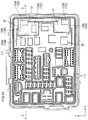
- the electrical junction box 10 has a horizontally elongated rectangular shape as a whole.
- the electrical junction box 10 includes a casing (a box, an exterior body) 11, a first circuit board 12 that is housed in the casing 11, and a second circuit board 13 that is housed in the casing 11 and disposed over the first circuit board 12.
- the electrical junction box 10 includes connectors (operational electrical components) 14 to each of which a counter connector (not illustrated) that is provided at an end portion of an electric wire (a wire harness), which is electrically connected to the battery or the vehicle electric component, is connected.
- the electrical junction box 10 further includes fuse connectors (the operational electrical components) 15 each of which is configured to receive and to be connected to a fuse which is not illustrated.
- the counter connectors and the fuses are configured to be inserted in the electrical junction box 10 from the front side in the Z-axis direction.
- a long-side direction, a short-side direction, and a thickness direction of the electrical junction box 10 correspond to the X-axis direction, the Y-axis direction, and the Z-axis direction, respectively, in each drawing.
- the casing 11 is made of synthetic resin. As illustrated in FIG. 1 , the casing 11 has the same horizontally elongated rectangular shape as the electrical junction box 10.
- the casing 11 includes assembled two casing members 16, 17 each on the front side or the rear side (in a vertical direction in FIG. 1 ).
- One of the casing members 16, 17 that is disposed on the rear side (a lower side in FIG. 1 ) is a first casing member (a lower case) 16 and the other one of them that is disposed on the front side (an upper side in FIG. 1 ) is a second casing member (an upper case) 17.
- the first casing member 16 and the second casing member 17 that are assembled have an internal space having a predetermined size.
- the first circuit board 12 and the second circuit board 13 can be housed in the space.
- An assembling direction of the casing members 16, 17 corresponds to the Z-axis direction.
- the first casing member 16 has a box-like shape that opens toward the front side in the Z-axis direction (toward the upper side in FIG. 1 ).
- the first casing member 16 includes a bottom plate 16a that extends in the X-axis direction and the Y-axis direction (along a plate surface of the first circuit board 12) and an outer plate 16b that extends upward from an outer edge of the bottom plate 16a in the Z-axis direction and has a substantially rectangular tubular shape.
- Multiple support projections 16c that are configured to support the first circuit board 12 from the rear side are dispersedly disposed on a surface of the bottom plate 16a of the first casing member 16.
- the bottom plate 16a includes a screw receiving part 16d to which a screw is fastened to fix the second casing member 17.
- locking portions 16e are disposed on an inner surface of the outer plate 16b to maintain the assembled state of the casing members 16, 17.
- Each locking portion 16e is a tab-like protrusion and formed at a front edge of the outer plate 16b.
- the locking portions 16e are disposed on each of long sides and short sides of the outer plate 16b.
- the second casing member 17 has a box-like shape that opens toward the rear side in the Z-axis direction (toward the lower side in FIG. 1 ).
- the second casing member 17 generally includes a cover 17a and an inner plate 17b.
- the cover 17a faces the bottom plate 16a of the first casing member 16 and covers the first circuit board 12 and the second circuit board 13 from the front side.
- the inner plate 17b extends from an outer edge of the cover 17a toward the rear side and has a substantially rectangular tubular shape.
- the cover 17a includes connector hoods 17c and fuse attachments 17d.
- the connector hoods 17c each constitute the connector 14 together with a connector terminal 18 which is mounted on the first circuit board 12.
- the connector terminal 18 will be described later.
- the fuse attachments 17d each configure the fuse connector 15 together with a fuse connecting terminal 19 mounted on the first circuit board 12. Almost all of the connector hoods 17c and the fuse attachments 17d (specifically, except for the connector hood 17c that is disposed at an upper left corner in FIG. 3 ) are concentrated at a middle of the cover 17a in the long-side direction thereof.
- Each connector hood 17c surrounds multiple connector terminals 18 collectively and has a substantially rectangular tubular shape that opens toward the front side such that the counter connector can be fitted thereto from the front side.
- Each fuse attachment 17d surrounds the fuse connecting terminals 19 individually and has a substantially rectangular tubular shape that opens toward the front side and has fuse attachment spaces to which the above-described fuses can be individually fitted from the front side.
- the cover 17a includes a closed section 17f at one end in the long-side direction thereof (an upper right end in FIG. 1 , a right end in FIG. 3 ).
- the closed section 17f is located slightly above the connector hoods 17c and the fuse attachments 17d and has no opening.
- the closed section 17f can cover substantially the entire area of the second circuit board 13.
- the inner plate 17b is configured to be fitted to an inner surface of the outer plate 16b of the first casing member 16. As illustrated in FIG. 2 and FIG. 4 , in the casings 16, 17 that are assembled, the inner plate 17b is surrounded by the outer plate 16b along its entire outer circumference from the outer side.
- the inner plate 17b has locking protrusions 17e at its outer surface. The locking protrusions 17e and the locking portions 16e of the outer plate 16b are locked together to maintain the assembled state of the casing members 16, 17.
- the locking protrusions 17e each protrude from the outer surface of the inner plate 17b. Multiple locking protrusions 17e are disposed on long sides and short sides of the inner plate 17b.
- the first circuit board 12 is made of synthetic resin, and extends along a plate surface of the bottom plate 16a of the first casing member 16 with a horizontally elongated plate shape extending over substantially entire area of the bottom plate 16a as illustrated in FIG. 1 .
- the connector terminals 18 that constitute the connector 14 the fuse connecting terminals 19 that constitute the fuse connectors 15, and relays (the start electrical component, the operational electrical component) 20 are mounted.
- the first circuit board 12 has a circuit pattern (not illustrated) that is connected to the connector terminals 18, the fuse connecting terminals 19, and the relays 20. The current supplied from the battery flows through the circuit pattern.
- the first circuit board 12 is a "power circuit board” that relays the power supply from the battery to the vehicle electrical components.
- the relay 20 mounted on the first circuit board 12 is configured to control whether or not to supply a current to the first circuit board 12.
- the connector terminals 18 protrude from the front plate surface of the first circuit board 12 toward the front side and each have a tab-like shape.
- the connector terminals 18 are disposed on the first circuit board 12 in bunches such that each bunch is disposed in an area surrounded by each connector hoods 17c.
- the fuse connecting terminals 19 protrude from the front plate surface of the first circuit board 12 toward the front side and each have a tuning-fork like shape that has a two-pronged front end.
- the fuse connecting terminals 19 are disposed beside one another on the first circuit board 12 such that the fuse connecting terminals 19 are individually disposed in each fuse attachment space of the fuse attachment 17d.
- almost all of the connector terminals 18 and the fuse connecting terminals 19 are concentrated at the middle of the first circuit board 12 in the long-side direction.
- the relay 20 is an electrical component that is configured to control whether or not to supply the power from the battery to a vehicle electrical component. As illustrated in FIG. 1 , multiple relays 20 are provided for the respective vehicle electrical components to control whether or not to supply the current thereto. When the current starts flowing through the relay 20, the current is supplied to the corresponding vehicle electrical component. When no current flows through the relay 20, the current is not supplied to the corresponding vehicle electrical component. As illustrated in FIG. 1 and FIG. 3 , the relays 20 are disposed on each end section of the first circuit board 12 in the longitudinal direction. In other words, the relays 20 are dispersedly disposed with the connector terminals 18 and the fuse connecting terminals 19 therebetween. The middle of the first circuit board 12 in the long-side direction is an area for the connector terminals 18 and the fuse connecting terminals 19. The end sections in the long-side direction are areas for the relays 20.
- the relay 20 includes a relay case (an electrical component case) 20a that is made of synthetic resin, a terminal portion 20b that is made of metal and has a part protruding outward from the bottom surface of the relay case 20a, and a coil 20c that is housed in the relay case 20a.
- the relay case 20a has a block-like shape elongated in the z-axis direction as a whole and has a housing space for the terminal portion 20b and the coil 20c therein.
- the relay case 20a includes a base 20a1 that has a bottom surface and a cover 20a2 that has a substantially cylindrical shape with a bottom and covers the base 20a1.
- the cover 20a2 includes ventilation holes 20a2a (six ventilation holes 20a2a) that communicate with the outer space at its ceiling (a portion facing a movable portion of a movable contact terminal portion 20b3, which will be described later).
- the ventilation holes 20a2a are located beside one another at intervals. Through the ventilation holes 20a2a, the moisture generated by the heated coil 20c can be released to the outside, and the heat generated on the terminal portion 20b and the coil 20c therein can be released.
- the terminal portion 20b includes two coil terminal portion 20b1 each of which is connected to each end portion of a winding wire of the coil 20c in the relay case 20a, a fixed contact terminal portion 20b2 having a fixed contact FC, and a movable contact terminal portion 20b3 having a movable contact MC.
- the movable contact terminal portion 20b3 has a cantilever-like shape and has a movable portion that can be elastically deformed by a magnetic field of the coil 20c.
- the movable contact MC at a front end of the movable contact terminal portion 20b3 is movable toward or away from the fixed contact FC of the fixed contact terminal portion 20b2.
- the movable contact terminal portion 20b3 includes a terminal body 20b3a having the movable portion and a contact member 20b3b having the movable contact MC.
- the former (the terminal body 20b3a) is made of metal material that provides high durability to a spring included in the movable portion.
- the latter (the contact member 20b3b) is made of metal material having high conductivity.
- a magnetic member 20d that is a magnetic body is attached to the movable portion of the terminal body 20b3a.
- the magnetic member 20d is made of magnetic material such as iron.
- the magnetic member 20d is disposed between the movable portion and the coil 20c and is configured to displace the movable portion by electromagnetic induction of the coil 20c.
- the fixed contact FC and the movable contact MC are away from each other and not in contact with each other, and thus the current does not flow between the fixed contact terminal portion 20b2 and the movable contact terminal portion 20b3.
- the magnetic member 20d is attracted toward the coil 20c by the electromagnetic induction of the coil 20c, and the movable contact terminal portion 20b3 is displaced such that the movable contact MC thereof comes in contact with the fixed contact FC.
- the current starts flowing between the fixed contact terminal portion 20b2 and the movable contact terminal portion 20b3.
- the relay 20 has a contact structure of a form A contact.
- the terminal portions 20b1, 20b2, 20b3 each have a portion that protrudes from the bottom surface of the relay case 20a and is soldered to the first circuit board 12 and connected to the circuit pattern at the portion.
- the relay 20 includes two kinds of relay to each of which the current is supplied at a different timing according to a vehicle electrical component to be controlled.
- the relay 20 includes a start relay 20A and an operational relay 20B.
- the start relay 20A is a start electrical component to which a current is supplied at the start of the vehicle.
- the operational relay 20B is an operational electrical component to which a current is supplied during the operation of the vehicle.
- the start relay 20A is configured to control whether or not to supply the current to vehicle electrical components such as a starter, an engine control unit, a fuel pump, and an ignition.
- the operational relay 20B is configured to control whether or not to supply the current to vehicle electrical components such as various lamps, an air conditioner, a power window, a power steering, a power seat, a horn, a wiper, a defroster, and a seat heater.
- vehicle electrical components such as various lamps, an air conditioner, a power window, a power steering, a power seat, a horn, a wiper, a defroster, and a seat heater.
- the connector 14 (the connector terminals 18) and the fuse connector 15 (the fuse connecting terminals 19) are the operational electrical component, like the above-described start relay 20B, because the current is supplied thereto during the operation of the vehicle.
- the “start electrical component (the start relay 20A)” is not limited to one to which the current is supplied only at the start of the vehicle, but may be one to which the current is supplied during the operation of the vehicle and when the operation of the vehicle is stopped in addition to at the start of the vehicle.
- the “operational electrical component (the operational relay 20B, the connector 14, and the fuse connector 15)” is not limited to one to which the current is always supplied during the operation of the vehicle, but may be one to which the current is supplied and no current is supplied during the operation of the vehicle (for example, to which the current is usually supplied and temporarily not supplied, or to which the current is usually not supplied and temporarily supplied).
- the “operational electrical component” is not limited to one to which the current is supplied only during the operation of the vehicle, but may be one to which the current is supplied during the operation of the vehicle and when the operation of the vehicle is stopped.
- the second circuit board 13 is made of synthetic material, and as illustrated in FIG. 1 , extends parallel to the plate surface of the first circuit board 12 with a vertically elongated plate shape.
- the second circuit board 13 is smaller than the first circuit board 12.
- the second circuit board 13 is housed in the casing 11 such that the long-side direction thereof corresponds to the short-side direction (the Y-axis direction) of the first circuit board 12 and the short-side direction thereof corresponds to the long-side direction (the X-axis direction) of the first circuit board 12.
- the second circuit board 13 is located in the casing 11 at a position closer to an end in the long-side direction (the X-axis direction) of the casing 11.
- the second circuit board 13 is disposed at a position overlapping with an end section of the first circuit board 12 in the long-side direction and the closed section 17f of the cover 17a of the second casing member 17. As illustrated in FIG. 4 , the second circuit board 13 is disposed on the front side of the first circuit board 12 in the Z-axis direction with a predetermined distance therebetween. In this configuration, the housing space for the relays 20 is defined between the first circuit board 12 and the second circuit board 13. In other words, the second circuit board 13 is positioned so as to have the relays 20 between the second circuit board 13 and the first circuit board 12.
- various electrical components such as a resistor, a capacitor, a transistor, and a microcomputer are mounted and a circuit pattern (not illustrated) that is to be connected to the various electrical components are formed.
- each relay terminal portion 21 is mounted to the second circuit board 13.
- the other end of each relay terminal portion 21 is inserted into the first circuit board 12 to connect the circuit patterns of the first and second circuit boards 12, 13 through the relay terminal portion 21.
- the relay terminal portions 21 each include prismatic terminals that are arranged beside one another in a straight line in the X-axis direction or the Y-axis direction.
- the relay terminal portions 21 are each disposed on each short-side end of the second circuit board 13 and on one long-side end that is located on the outer side of the casing 11 (the right side in FIG. 6 ).
- the second circuit board 13 is a "control circuit board" that can control an operation state (whether or not to supply the current) of the relay 20 or other components, which are mounted on the first circuit board 12, by the mounted electrical components.
- positions of the relays 20 in the casing 11 are each determined depending on its kind as follow.
- the start relays 20A of the relays 20 are disposed relatively on the outer side in the casing 11 and the operational relays 20B are disposed relatively on the inner side in the casing 11.
- multiple start relays 20A are disposed on each end section in the long-side direction of the casing 11 and the first circuit board 12 such that the start relays 20A constitute two start relay groups 22, 23.
- the first start relay group 22 includes the relays 20 that are disposed on the end section (the end section on the left in FIG. 6 ) that is one of the end sections in the long-side direction and does not overlap with the second circuit board 13 in a plan view.
- the second start relay group 23 includes the relays 20 that are disposed on the end section (the end section on the right in FIG. 6 ) and overlaps with the second circuit board 13 in a plan view.
- multiple operational relays 20B are disposed between the second start relay group 23 and a group of the connectors 14 and the fuse connecting portions 15, which are concentrated at the middle of the casing 11 and the first circuit board 12 in the long-side direction.
- the operational relays 20B are located adjacent to the group of the connectors 14 and the fuse connecting portions 15, and are the operational electrical components like the connectors 14 and the fuse connectors 15.
- the operational electrical components are concentrated at the middle of the first circuit board 12 in the long-side direction. That is, the middle section of the first circuit board 12 in the long-side direction is an arrangement area for the operational electrical components and the end sections are arrangement areas for the start electrical components.
- the start relays 20A that are included in the first start relay group 22 include a total of five start relays 20A.
- Four of the start relays 20A are disposed on the end section in the long-side direction of the first circuit board 12 such that two pairs of them, each of which includes two start relays 20A adjacent to each other in the Y-axis direction, are disposed on each side in the Y-axis direction with the connector 14 that is disposed at the middle in the short-side direction (the Y-axis direction) therebetween.
- the remaining one of the start relays 20A is disposed on the inner side in the long-side direction (the X-axis direction) at a position adjacent to one of the start relays 20A that is disposed on the end portion extending in the short-side direction (at a lower end portion illustrated in FIG. 6 ).
- the four of the start relays 20A that are disposed with the connector 14 therebetween are disposed on the outer end portion of the casing 11.
- One of the start relays 20A is disposed at one corner of the casing 11 (a lower left corner illustrated in FIG. 6 ).
- the start relays 20A that are included in the second start relay group 23 include a total of three start relays 20A.
- Two of the start relays 20A are disposed on the end section in the long-side direction (the first space S1) of the first circuit board 12 with the relay terminal portion 21, which is disposed at the middle in the short-side direction, therebetween. The remaining one of them is located at the middle and adjacent to the relay terminal portion 21 in the long-side direction.
- Two start relays 20A that are disposed with the relay terminal portion 21 therebetween are disposed on the outer end portions of the casing 11, particularly at two corners of the casing 11 (a right upper corner and a right lower corner in FIG. 6 ).
- the operational relay 20B includes five operational relays 20B that are disposed between the relay terminal portions 21 that are disposed at respective ends in the short-side direction of the first circuit board 12.
- the operational relay 20B further includes two operational relays 20B that are respectively disposed more interior or more exterior in the long-side direction than the operational relay 20B that is disposed at the middle in the short-side direction of the first circuit board 12.
- the total of seven operational relays 20B are disposed at positions overlapping with the second circuit board 13 in a plan view together with the second start relay group 23 and disposed between the first circuit board 12 and the second circuit board 13 ( FIG. 4 ).
- the electrical junction box 10 includes surrounding heat shield walls (heat shield walls) 24 each of which surrounds the start relay 20A included in the first start relay group 22 and is disposed between the start relay 20A and the connector 14, the fuse connector 15, or the start relay 20B.
- the surrounding heat shield wall 24 is integrally formed with the cover 17a of the second casing member 17 and has a substantially rectangular tube shape with an opening that opens toward the rear side, i.e., toward the first circuit board 12 side.
- the surrounding heat shield wall 24 includes a ceiling wall 24a that faces the first circuit board 12 and a side wall 24b that has a substantially rectangular tubular shape and extends from an outer edge of the ceiling wall 24a toward the rear side.
- the surrounding heat shield wall 24 can surround an outer surface of the start relay 20A except for the bottom surface (the surface facing the first circuit board 12). A part of the surrounding heat shield wall 24 (a part facing the outer plate 16b included in the first casing member 16) is also used as the inner plate (an outer peripheral wall) 17b included in the second casing member 17.
- the surrounding heat shield wall 24 is in contact with or adjacent to the plate surface of the first circuit board 12 at its opening edge. Accordingly, in this state, the start relays 20A are disposed between the first circuit board 12 and the surrounding heat shield wall 24, and is housed in a closed space with little gap. The outer surface of each start relay 20A is surrounded by the first circuit board 12 and the surrounding heat shield wall 24 over its substantially entire area. The surrounding heat shield walls 24 form a shape that surrounds the start relays 20A included in the first start relay group 22 individually (an individual surrounding type).
- the number of surrounding heat shield walls 24 is the same as the number of the start relays 20A included in the first start relay group 22 (five surrounding heat shield walls 24 in FIG. 6 ).
- the start relays 20A included in the first start relay group 22 are each housed in the independent housing space of each surrounding heat shield wall 24.
- two side walls 24b of the heat shield walls 24 are disposed between two adjacent start relays 20A included in the first start relay group 22 in the X-axis direction or the Y-axis direction on the first circuit board 12.
- adjacent two of the surrounding heat shield walls 24 are connected to each other via a heat shield wall connecting member 25.
- the heat shield wall connecting member 25 connects the side walls 24b of the adjacent surrounding heat shield walls 24 at their opposing portions.
- the heat shield wall connecting member 25 is disposed on each side wall 24b at a position closer to the opening edge than the ceiling wall 24a in the Z-axis direction.
- the surrounding heat shield wall 24 is connected to the connector hood 17c that is included in the adjacent connector 14 via a connector/heat shield wall connecting member 26.
- the connector/heat shield wall connecting member 26 connects the side wall 24b of the surrounding heat shield wall 24 and the connector hood 17c at their opposing portions and is disposed substantially at the same position in the Z-axis direction as the heat shield wall connecting member 25. Further, as illustrated in FIG. 4 , the surrounding heat shield wall 24 is connected to the fuse attachment 17d that is included in the fuse connector 15 adjacent to the surrounding heat shield wall 24 via a fuse connector/heat shield wall connecting member 27.
- the fuse connector/heat shield wall connecting member 27 connects the side wall 24b of the surrounding heat shield wall 24 and the fuse attachment 17d at their opposing portions.
- the fuse connector/heat shield wall connecting member 27 is disposed substantially at the same position in the Z-axis direction as the heat shield wall connecting member 25.
- the electrical junction box 10 includes a partition heat shield wall (a heat shield wall) 28 that is disposed between the start relays 20A included in the second start relay group 23 and the operational relays 20B that are adjacent to the second start relay group 23.
- the partition heat shield wall 28 divides the space between the first circuit board 12 and the second circuit board 13 into a first space S1 on an outer side of the casing 11 and a second space S2 on an inner side of the casing 11.
- the start relays 20A included in the second start relay group 23 are disposed.
- the operational relays 20B are disposed.
- the first space S1 includes an outer end portion in the long-side direction of the casing 11, particularly, two corners of the outer end portion.
- the partition heat shield wall 28 is a separate member from the circuit boards 12, 13 and the casing members 16, 17, and is attached to the first circuit board 12.
- the partition heat shield wall 28 extends across the first circuit board 12 in the Y-axis direction while being bent at the middle in a plan view.
- the partition heat shield wall 28 extends between the relay terminal portions 21 on the ends in the short-side direction of the first circuit board 12 while being bent outward in the long-side direction of the first circuit board 12 at the middle thereof.
- the partition heat shield wall 28 surrounds and closes the second space S2 together with the first circuit board 12, the second circuit board 13, and the two described relay terminal portions 21.
- the partition heat shield wall 28 has a configuration that allows the first space S1 to open toward a side opposite to the second space S2, i.e., outwardly in the long-side direction (the X-axis direction) of the casing 11, and in a direction perpendicular to (intersecting with) an arrangement direction of the first space S1 and the second space S2, i.e., outwardly in the short-side direction (the Y-axis direction) of the casing 11. That is, the partition heat shield wall 28 allows the first space S1 to open toward the outside of the casing 11 except for the direction toward the second space S2 side, i.e., in three directions.
- the partition heat shield wall 28 includes mounts 28a on its bottom at its ends in the Y-axis direction.
- the mounts 28a each extend along the plate surface of the first circuit board 12.
- a vertical reinforcing rib 29 that connects a surface of the mount 28a and a surface of the partition heat shield wall 28 is provided.
- the mount 28a extends in the thickness direction of the partition heat shield wall 28 over the partition heat shield wall 28.
- a pair of the vertical reinforcing ribs 29 is disposed on each mount 28a.
- the vertical reinforcing rib 29 has a substantially triangular shape in a side view. As illustrated in FIG.
- the partition heat shield wall 28 has four bend portions at which the partition heat shield wall 28 is bent at a substantially right angle.
- a horizontal reinforcing rib 30 connects surfaces at the bend portions.
- the horizontal reinforcing rib 30 has a substantially triangle shape in a plan view.
- Two legs other than a hypotenuse extend along the surface of the bend portion of the partition heat shield wall 28.
- a part of the partition heat shield wall 28 that is disposed on the most outer side of the casing 11 and extends along the Y-axis direction has an outer surface that extends along the relay terminal portion 21 that is disposed at the middle in the short-side direction of the first circuit board 12.
- the present embodiment has the above-described configuration, and the operation thereof will be described.
- a predetermined signal is transmitted from the second circuit board 13 to the first circuit board 12 through the relay terminal portion 21 to supply the current to the start relays 20A mounted on the first circuit board 12.
- the current is supplied to the vehicle electrical components (such as a starter, an engine control unit, a fuel pump, and an ignition) which are controlled by the start relays 20A to start the component such as the engine that is mounted in the vehicle, and thus the vehicle is in an operable state.
- the current is supplied or not supplied to the operational electrical components (the operational relay 20B, the connector 14, and the fuse connector 15) by a predetermined signal that is transmitted from the second circuit board 13 to the first circuit board 12 through the relay terminal portion 21 according to the operation of the user.
- the current is supplied to the operational relays 20B, the current is supplied to the vehicle electrical components (such as various lamps, an air conditioner, a power window, a power steering, a power seat, a horn, a wiper, a defroster, and a seat heater) which are to be controlled by the operational relays 20B. Due to the supplied current, heat is generated on the operational electrical components and the circuit boards 12, 13. The amount of the generated heat is likely to be proportional to an accumulated time and the amount of supplied current.
- the relay case 20a of the start relay 20A that is the start electrical component
- a temperature of the relay case 20a increases.
- the relay case 20a does not have high heat dissipation. Accordingly, if the heat generated on the operation electrical components during the operation of the vehicle is transmitted to the relay case 20a, the heat is likely to be accumulated on the relay case 20a.
- the terminal portions 20b each having the fixed contact FC and the movable contact MC of the start relay 20A are made of metal material that has higher thermal conductivity than the resin material constituting the relay case 20a and are connected to the circuit pattern of the first circuit board 12 made of metal material, and heat sink effect occurs at a low temperature.
- the temperature of the relay case 20a becomes relatively high, and the temperature of the terminal portions 20b having the fixed contact FC and the movable contact MC become relatively low. Accordingly, a difference in the temperature between the relay case 20a and the terminal portions 20b is likely to be large.
- the fixed contact terminal portion 20b2 having the fixed contact FC is likely to have a lower temperature than the movable contact terminal portion 20b3 having the movable contact MC, because the movable contact terminal portion 20b3 includes the magnetic member 20d that is to be in contact with the coil 20c and is likely to have a higher temperature due to the heat transmitted from the coil 20c.
- the vaporized moisture may exist due to the heat caused by the supply of the current.
- the condensation is likely to selectively occur on the fixed contact FC of the fixed contact terminal portion 20b2.
- the condensation may be frozen in a low temperature environment.
- the fixed contact FC and the movable contact MC of the terminal portions 20b cannot be in contact with each other when the operation of the vehicle is tried to be restarted, which may result in a malfunction of the start relay 20A.
- the vehicle is not likely to be started, for example, because the engine is not started.
- the surrounding heat shield walls 24 are disposed between the start relays 20A included in the first start relay group 22 and the operational electrical components (the operational relay 20B, the connector 14, and the fuse connector 15), the heat generated on the operational electrical components during the operation of the vehicle is hardly transmitted to the relay cases 20a of the start relays 20A included in the first start relay group 22, and thus the temperature of each relay case 20a is less likely to increase. Accordingly, even if the operation of the vehicle is stopped in the low temperature and high humidity environment, a difference in the temperature between the relay case 20a of each start relay 20A included in the first start relay group 22 and the fixed contact terminal portion 20b2 having the fixed contact FC can be made smaller.
- the surrounding heat shield walls 24 each have the substantially rectangular tubular shape with a bottom that opens toward the first circuit board 12 and individually surround each of the start relays 20A, the start relays 20A are hardly exposed to the operational electrical component side, and thus high heat shield effect can be obtained and the temperature difference can be made smaller.
- the start relays 20A included in the first start relay group 22 include the start relays 20A that are disposed on the outer end portion of the casing 11 and disposed more exterior than the operational electrical component, and further includes the start relay 20A that is disposed at the corner of the outer end portion of the casing 11, the heat of the relay case 20a of the start relay 20A can be released to the outside of the casing 11, and thus the decrease in the temperature of the relay case 20a in the low temperature environment can be facilitated and the difference in the temperature can be made smaller.
- the condensation and the freezing of the moisture in the relay case 20a of the start relay 20A included in the first start relay group 22 hardly occur at the fixed contact FC of the fixed contact terminal portion 20b2. Thus, a situation in which the current is not supplied to the start relay 20A at the start of the vehicle can be avoided.
- the partition heat shield wall 28 is disposed between the start relays 20A included in the second start relay group 23 and the operational electrical components, the heat generated on the operational electrical components during the operation of the vehicle is hardly transmitted to the relay cases 20 of the start relays 20A included in the second start relay group 23, and thus the temperature of the relay case 20a is less likely to increase. Accordingly, even if the operation of the vehicle is stopped in the low temperature and high humidity environment, the difference in the temperature between the relay case 20a of the start relay 20A included in the second start relay group 23 and the fixed contact terminal portion 20b2 having the fixed contact FC can be made smaller.
- the partition heat shield wall 28 divides the space between the first circuit board 12 and the second circuit board 13 into the first space S1 on the outer side and the second space S2 on the inner side.
- the start relays 20A included in the second start relay group 23 are disposed.
- the operational relays 20B that are the operational electrical components are disposed.
- the partition heat shield wall 28 allows the first space S1 to open toward the outside of the casing 11 except for the second space S2 side, i.e., in three directions, the heat can be easily diffused from the relay cases 20 of the start relays 20A included in the second start relay group 23 to the outside.
- the first space S1 includes the outer end portion of the casing 11 and further the corners of the outer end portion, and the start relays 20A included in the second start relay group 23 are disposed on the outer end portion and the corner. With this configuration, the heat generated on the relay case 20a can be further easily diffused to the outside.
- the electrical junction box 10 includes the casing 11 configured to be mounted in a vehicle, the start relay (the start electrical component) 20A housed in the casing 11 and to which a current is supplied at least at a start of the vehicle, the operational electrical component (the operational relay 20B, the connector 14, and the fuse connector 15) housed in the casing 11 and to which the current is supplied at least during the operation of the vehicle, and the surrounding heat shield wall (the heat shield wall) 24 disposed between the start relay 20A and at least one of the operational relay 20B, the connector 14, and the fuse connector 15 that are the operational electrical component.
- the start relay 20A includes the relay case (the electrical component case) 20a and the terminal portion 20b (the fixed contact point terminal portion 20b2) housed in the relay case 20a and having the fixed contact FC.
- the operation of the vehicle is started by the current supplied to the start relay 20A that is housed in the casing 11, and during the operation, the current is supplied to at least one of the operational relay 20B, the connector 14, and the fuse connector 15 that are the operational electrical components housed in the casing 11.
- the current is supplied to at least one of the operational relay 20B, the connector 14, and the fuse connector 15 that are the operational electrical components housed in the casing 11.
- the relay case 20a of the start relay 20A has a temperature higher than that of the terminal portion 20b having the fixed contact FC, and thus a large difference in the temperature occurs. Accordingly, the condensation and the freezing of the moisture in the relay case 20a are likely to occur on the fixed contact FC, which may result in the malfunction of the start relay 20A.
- the surrounding heat shield wall 24 is disposed between the start relay 20A and at least one of the operational relay 20B, the connector 14, and the fuse connector 15 that are the operational electrical components, the heat generated on at least one of the operational relay 20B, the connector 14, and the fuse connector 15 that are the operational electrical components is hardly transmitted to the relay case 20a of the start relay 20A, and thus the temperature of the relay case 20a is less likely to increase. Accordingly, even if the operation of the vehicle is stopped in a low temperature environment, the difference is less likely to occur in the temperature between the relay case 20a of the start relay 20A and the terminal portion 20b having the fixed contact FC. Thus, the condensation and the freezing of the moisture in the relay case 20a hardly occur on the fixed contact FC, and thus the situation in which the current cannot be supplied to the start relay 20A at the restart of the vehicle can be avoided.
- the start relay 20A is not limited to one to which the current is supplied only at the start of the vehicle, but may be one to which the current is supplied during the operation of the vehicle and when the operation of the vehicle is stopped in addition to at the start of the vehicle.
- the operational relay 20B, the connector 14, and the fuse connector 15 that are the operational electrical components are not limited to one to which the current is always supplied during the operation of the vehicle, but may be one to which the current is supplied and no current is supplied during the operation of the vehicle (for example, to which the current is usually supplied and temporarily not supplied, or to which the current is usually not supplied and temporarily supplied).
- At least one of the operational relay 20B, the connector 14, and the fuse connecting portion 15 that are the operational electrical components is not limited to one to which the current is supplied only during the operation of the vehicle, but may be one to which the current is supplied during the operation of the vehicle and when the operation of the vehicle is stopped.
- the casing 11 houses the first circuit board (the circuit board) 12 on which the start relay 20A and at least one of the operational relay 20B, the connector 14, and the fuse connector 15 that are the operational electrical components are mounted.
- the first circuit board (the circuit board) 12 has the circuit pattern connected to the terminal portion 20b. In this configuration, the terminal portion 20b having the fixed contact FC of the start relay 20A is connected to the circuit pattern formed on the first circuit board 12.
- a decrease in the temperature of the terminal portion 20b is likely to be facilitated by the circuit pattern in a low temperature environment, but the condensation and the freezing hardly occur on the fixed contact FC, because the temperature of the relay case 20a is less likely to increase and the difference in the temperature between the relay case 20 and the terminal portion 20b having the fixed contact FC is made smaller by the surrounding heat shield wall 24 as described above.
- the surrounding heat shield wall 24 has the tubular shape having the bottom and the opening that opens toward the first circuit board 12, and surrounds the start relay 20A.
- the start relay 20A is disposed in the space defined by the first circuit board 12 and the surrounding heat shield wall 24, which has the tubular shape with the bottom and the opening that opens toward the first circuit board 12, the start relay 20A is hardly exposed, or exposed only a little, to a side of at least one of the operational relay 20B, the connector 14, and the fuse connector 15 that are the operational electrical components.
- the surrounding heat shield walls 24 are each arranged to surround each of the start relays 20A.
- higher heat shield can be obtained, compared to a surrounding heat shield wall that collectively surrounds the multiple start relays 20A.
- surrounding heat shield walls 24 are located adjacent to each other, and the surrounding heat shield wall connecting member 25 is provided to connect the adjacent surrounding heat shield walls 24. With this configuration, the strength of each surrounding heat shield wall 24 can be maintained high by the surrounding heat shield wall connecting member 25.
- the start relay 20A is disposed more exterior than at least one of the operational relay 20B, the connector 14, and the fuse connector 15 that are the operational electrical components, in the casing 11.
- the decrease in the temperature of the relay case 20a of the start relay 20A in the low temperature environment can be facilitated, because the heat can be easily released to the outside at the outer side in the casing 11 compared to at the inner side. Accordingly, the difference in the temperature between the relay case 20a and the terminal portion 20b having the fixed contact FC can be further made smaller.
- the start relay 20A is disposed on the outer end of the casing 11. With this configuration, the decrease in the temperature of the relay case 20a in the low temperature environment can be further facilitated, and the difference in the temperature between the relay case 20a and the terminal portion 20b having the fixed contact FC can be further made smaller, because the start relay 20A is disposed on the outer end of the casing 11 where the heat can be particularly easily released to the outside.
- the surrounding heat shield wall 24 is integrally formed with the casing 11. This is preferred for the reason that the production cost can be reduced, e.g., the number of steps for assembling can be reduced, compared to the case in which a heat shield wall is a separate member from the casing 11.
- the connector 14 is disposed at a position adjacent to the surrounding heat shield wall 24, and the connector/heat shield wall connecting member 26 is provided to connect the surrounding heat shield wall 24 and the connector 14, which are adjacent to each other. With this configuration, the strength of the surrounding heat shield wall 24 and the connector 14 can be maintained high by the connector/heat shield wall connecting member 26.
- the start electrical component is the start relay 20A
- the contact of the terminal portion 20b at least has the fixed contact FC and the movable contact MC, which is movable toward or away from the fixed contact FC.
- the electrical junction box 10 of this embodiment includes the casing 11 configured to be mounted on the vehicle, the start relay (the start electrical component) 20A that includes the relay case (the electrical component case) 20a and the terminal portion 20b (the fixed contact terminal portion 20b2) that is housed in the relay case 20a and has the fixed contact FC, the operational electrical component (the operational relay 20B, the connector 14, and the fuse connector 15) that is housed in the casing 11 and to which the current is supplied at least during the operation of the vehicle, the first circuit board (the circuit board) 12 on which the start relay 20A and at least one of the operational relay 20B, the connector 14, and the fuse connector 15 that are the operational electrical components are mounted and has the circuit pattern connected to the terminal portion 20b, the second circuit board (the plate member) 13 that is arranged such that at least the start relay 20A is disposed between the first circuit board 12 and the second circuit board 13, and the partition heat shield wall (the heat shield wall) 28 that is disposed between the start relay 20A and at least one of the operational relay 20B,
- the operation of the vehicle is started by the current supplied to the start relay 20A that is housed in the casing 11, and during the operation, the current is supplied to at least one of the operational relay 20B, the connector 14, and the fuse connector 15 that are the operational electrical components housed in the casing 11.
- the current is supplied to at least one of the operational relay 20B, the connector 14, and the fuse connector 15 that are the operational electrical components housed in the casing 11.
- heat is generated on at least one of the operational relay 20B, the connector 14, and the fuse connector 15 that are the operational electrical components, due to the supply of the current.
- the temperature of the relay case 20a increases.
- the relay case 20a since the start relay 20A is disposed between the first circuit board 12 and the second circuit board 13, the relay case 20a does not have high heat dissipation. If the heat is transmitted from at least one of the operational relay 20B, the connector 14, and the fuse connector 15 that are the operational electrical components to the relay case 20a, the heat is likely to be accumulated on the relay case 20a. If the operation of the vehicle is stopped in the low temperature environment, the difference in the temperature between the relay case 20a of the start relay 20A and the terminal portion 20b having the fixed contact FC is likely to be made large, because the terminal portion 20b of the start relay 20A that is connected to the circuit pattern of the first circuit board 12 is more easily cooled than the relay case 20a. Accordingly, the condensation and the freezing of the moisture in the relay case 20a are likely to occur on the fixed contact FC, which may result in a malfunction of the start relay 20A.
- the partition heat shield wall 28 is disposed between the start relay 20A and at least one of the operational relay 20B, the connector 14, and the fuse connector 15 that are the operational electrical components, the heat generated on at least one of the operational relay 20B, the connector 14, and the fuse connector 15 that are the operational electrical components during the operation of the vehicle is hardly transmitted to the relay case 20a of the start relay 20A, and thus the temperature of the relay case 20a is less likely to increase. Accordingly, even if the operation of the vehicle is stopped in the low temperature environment, the difference in the temperature between the relay case 20a of the start relay 20A and the terminal portion 20b having the fixed contact FC can be made smaller. Thus, the condensation and the freezing of the moisture in the relay case 20a hardly occur on the fixed contact FC, and the situation in which the current is not supplied to the start relay 20A at the restart of the vehicle can be avoided.
- the partition heat shield wall 28 divides the space between the first circuit board 12 and the second circuit board 13 into the first space S1 on the outer side and the second space S2 on the inner side of the casing 11, and the start relay 20A is disposed in the first space S1 and at least one of the operational relay 20B, the connector 14, and the fuse connector 15 that are the operational electrical components is disposed in the second space S2.
- the decrease in the temperature of the relay case 20a of the start relay 20A at a time when the operation of the vehicle is stopped in the low temperature environment can be facilitated by such an arrangement of the start relay 20A in the first space S1, because the heat in the first space S1 on the outer side of the casing 11 can be easily released to the outside compared to the second space S2 on the inner side.
- the difference in the temperature between the relay case 20a and the terminal portion 20b having the fixed contact FC can be made smaller, because the heat from at least one of the operational relay 20B, the connector 14, and the fuse connector 15 that are the operational electrical components, is hardly transmitted to the relay case 20a of the start relay 20A due to the partition heat shield wall 28 that divides the space into the first space S1 on the outer side and the second space S2 on the inner side.
- the partition heat shield wall 28 has the configuration that allows the first space S1 to open at least toward the side opposite to the second space S2 side. With this configuration, the heat can be easily released from the first space S1 to the outside compared to the case in which a partition heat shield wall surrounds the first space S1, because the first space S1 opens to the side opposite to the second space S2, i.e., opens to the outside of the casing 11. Accordingly, the decrease in the temperature of the relay case 20a of the start relay 20A in the low temperature environment is further facilitated, and thus the difference in the temperature between the relay case 20a and the terminal portion 20b having the fixed contact FC can be further made smaller.
- the partition heat shield wall 28 has the configuration that allows the first space S1 to open in the direction intersecting with the arrangement direction of the first space S1 and the second space S2. With this configuration, the first space S1 can open to a larger area, and thus the heat can further easily be released from the first space S1 to the outside. Accordingly, the decrease in the temperature of the relay case 20a of the start relay 20A in the low temperature environment can be further facilitated.
- the first space S1 defined by the partition heat shield wall 28 includes the outer end portion of the casing 11, and the start relay 20A is disposed on the outer end portion.
- the first space S1 defined by the partition heat shield wall 28 includes the corner of the casing 11, and the start relay 20A is disposed at the corner.
- the decrease in the temperature of the relay case 20a can be further facilitated, because the first space S1 includes the corner and the start relay 20A is disposed at the corner where, among the outer end portion in the casing, the heat can be particularly easily released to the outside.
- the plate member is the second circuit board 13 having the circuit pattern connected to the circuit pattern of the first circuit board 12.
- the heat since the heat is generated on the second circuit board 13 due to the supply of the current to the circuit pattern thereof, the heat may be transmitted to the relay case 20a of the start relay 20A that is disposed between the second circuit board 13 and the first circuit board 12 and the difference in the temperature between the relay case 20a and the terminal portion 20b may be made large.
- the difference in the temperature between the relay case 20a and the terminal portion 20b having the fixed contact FC is made smaller, because the temperature of the relay case 20a is less likely to increase due to the partition heat shield wall 28. Accordingly, the condensation and the freezing hardly occur on the fixed contact FC.
- the relay terminal portion 21 through which the first circuit board 12 and the second circuit board 13 are connected to each other is provided, and the partition heat shield wall 28 has the surface that extends along the relay terminal portion 21.
- the relay terminal portion 21 can be guided by the surface of the partition heat shield wall 28 during the connection operation, and thus the assemble workability can be improved.
- the partition heat shield wall 28 has the bent shape in the cross section taken along the plate surface of the first circuit board 12. In this configuration in which the partition heat shield wall 28 has the bent shape, the mechanical strength thereof can be maintained high, and the partition heat shield wall 28 is hardly improperly deformed. Thus, the partition heat shield wall 28 hardly comes in contact with the start relay 20A or at least one of the operational relay 20B, the connector 14, and the fuse connector 15 that are the operational electrical components.
- the horizontal reinforcing rib (the reinforcing rib) 30 that connects the surfaces of the bend portions having the bent shape is disposed on the partition heat shield wall 28. With this configuration, the mechanical strength of the partition heat shield wall 28 can be further improved.
- the vertical reinforcing rib (the reinforcing member) 29 that extends along the plate surface of the first circuit board 12 and the surface of the partition heat shield wall 28 is provided.
- the mechanical strength of the partition heat shield wall 28 can be further improved by the vertical reinforcing rib 29, and the partition heat shield wall 28 is hardly improperly deformed. Accordingly, the partition heat shield wall 28 hardly comes in contact with at least one of the operational relay 20B, the connector 14, and the fuse connector 15 that are the operational electrical components.
- the start electrical component is the start relay 20A
- the contact of the terminal portion 20b at least has the fixed contact FC and the movable contact MC that is movable toward or away from the fixed contact FC.
- FIG. 8 A second embodiment of the present invention will be described with reference to FIG. 8 or FIG. 9 .
- a surrounding heat shield wall 124 has a different shape. Similar configurations, operations, and effects to those of the first embodiment will not be described.
- the surrounding heat shield wall 124 collectively surrounds the start relays 120A (collective surrounding type).
- the start relays 120A are housed in a pace defined by the surrounding heat shield wall 124 and a first circuit board 112.
- the surrounding heat shield wall 124 has a substantially rectangular tubular shape with a bottom and has a size sufficiently surrounding two start relays 120A adjacent to each other on the first circuit board 112.
- the surrounding heat shield wall 124 includes a ceiling wall 124a that is located over two start relays 120A in a plan view and a side wall 124b that extends from an outer edge of the ceiling wall 124a toward the first circuit board 112 and surrounds an outer surfaces of the start relays 120A except for the outer surfaces that face each other.
- the adjacent two start relays 120A are housed in a common space that is defined by the surrounding heat shield wall 124 and the first circuit board 112.
- the surrounding heat shield wall 124 having such a configuration can sufficiently block the heat from the operational electrical components, and thus the heat is hardly transmitted to the start relay 120A.
- a third embodiment of the present invention will be described with reference to FIG. 10 or FIG. 11 .
- a second heat shield wall 31 is provided and a partition heat shield wall 128 has a different shape. Similar configurations, operations, and effects to those of the first embodiment will not be described.
- the second heat shield wall 31 is disposed between the second circuit board 113 and start relays 120A included in a second start relay group 123 that is disposed in the first space S1 defined by the circuit boards 112, 113.
- the second heat shield wall 31 is connected to the partition heat shield wall 128 and extends from the top end of the partition heat wall 128, which extends upward from the first circuit board 112, toward the outside of a casing 111 to have eaves like shape.
- the partition heat shield wall 128 and the second heat shield wall 31 form a substantially L-shape in a cross section in the X-axis direction and the Z-axis direction. As illustrated in FIG.
- two second heat shield walls 31 are disposed with a meandered section of the partition heat shield wall 128, which is formed at a middle of the first circuit board 112 in the short-side direction (the Y-axis direction), therebetween in the Y-axis direction.
- Each of the second heat shield walls 31 extends over an area that covers the entire area of the start relays 120A included in the second start relay group 123 in a plan view.
- the partition heat shield wall 128 includes, in addition to a main wall 128a that extends across the first circuit board 112 in the short-side direction thereof and has the meandered section at its middle, a pair of side walls 128b that extends from each end of the main wall 128a toward the outside of the casing 111 along the long-side (the X-axis direction) of the first circuit board 112.
- the partition heat shield wall 128 has a configuration that allows the first space S1 to open toward only one side that is opposite to a side of the second space S2.
- the second heat shield wall 31 is connected to each of the side walls 128b of the partition heat shield wall 128, and thus higher mechanical strength can be obtained.
- the partition heat shield wall 128 and the second heat shield wall 31 define a pouch-like shape that opens toward the outside of the casing 111 along the X-axis direction.
- the second heat shield wall 31 is disposed between the start relay (the start electrical component) 120A and the second circuit board 113.
- the second heat shield wall 31 blocks the heat from the second circuit board 113, and thus the heat is hardly transmitted to the start relay 120A. Accordingly, a temperature of the relay case 20a is further less likely to increase, and thus a difference in the temperature between the relay case 10a and the terminal portion 20b having the fixed contact FC can be made smaller (see FIG. 7 ).
- partition heat shield wall 128 and the second heat shield wall 31 are continuous from each other. With this configuration, the mechanical strength can be improved in addition to the high heat shield effect.
- a fourth embodiment of the present invention will be described with reference to FIG. 12 .
- a relay 220 has a different shape. Similar configurations, operations, and effects to those of the first embodiment will not be described.
- a cover 220a2 included in a relay case 220a has fewer ventilation holes 220a2a than that in the first embodiment.
- a ceiling of the cover 220a2 (a portion facing a movable portion of a movable contact terminal portion 220b3, which will be described later) includes three ventilation holes 220a2a that are located beside one another. Three ventilation holes 220a2a are located closer to a base end (an end opposite to the side of the free end having the movable contact MC) side of the movable portion, which has a cantilever shape, of the movable contact terminal portion 220b3.
Abstract
Description
- The present invention relates to an electrical junction box.
- Conventionally, in a vehicle, an electrical junction box is employed, for example, as a module that is configured to control distribution of a current that is supplied from a power source to various vehicle electrical components. The electrical junction box houses various electrical components such as a relay and a fuse in a casing thereof.
Patent Document 1 discloses a known relay that is used in the electrical junction box having the above-described configuration. - Patent Document 1: Japanese Unexamined Patent Publication No.
2010-108661 - The relay described in
Patent Document 1 includes an electrical component case, a terminal portion housed in the electrical component case, a coil connected to the terminal portion, and a metal plate that is exposed to an inside and an outside of the electrical component case, in addition to the terminal portion. In this configuration, moisture in the electrical component case can be actively condensed on the metal plate by heat generated by the coil when an environmental temperature decreases. Accordingly, condensation on a contact of the terminal portion is less likely to occur, and thus poor conduction at the contact, which may be caused by frozen condensation, hardly occurs. - However, the technology described in
Patent Document 1 is made to prevent the poor conduction, which may be caused by the freezing, at the contact of the relay itself. The technology inPatent Document 1 does not take influence of other electrical components housed in the electrical junction box than the relay into consideration. Since the electrical junction box houses other various electrical components than the relay, influence of heat generated on such other electrical components, or influence of varied timing of supply/non-supply of the current depending on the kinds of electrical component, may cause the relay to easily have the problem of the poor conduction, which is caused by the freezing, at the contact. - The present invention was accomplished in view of the foregoing circumstances. An object of the present invention is to prevent a malfunction of a start electrical component.
- The electrical junction box according to the present invention includes a casing configured to be mounted in a vehicle, a start electrical component housed in the casing and to which a current is supplied at least at a start of the vehicle, an operational electrical component housed in the casing and to which a current is supplied at least during an operation of the vehicle, and a heat shield wall disposed between the start electrical component and the operational electrical component. The start electrical component includes an electrical component case and a terminal portion. The terminal portion is housed in the electrical component case and has a contact.
- In this configuration, at the start of the vehicle, the operation of the vehicle is started by the current supplied to the start electrical component that is housed in the casing, and during the operation, the current is supplied to the operational electrical component housed in the casing. Thus, during the operation of the vehicle, heat is generated on the operational electrical component due to the supply of the current. At this time, if the heat is transmitted from the operational electrical component to the electrical component case of the start electrical component, the electrical component case of the start electrical component has a temperature higher than that of the terminal portion having the contact, and thus a large difference in the temperature occurs. Accordingly, the condensation and the freezing of the moisture in the electrical component case easily occur on the contact, which may result in the malfunction of the start electrical component.
- In this embodiment, since the heat shield wall is disposed between the operational electric component and the start electrical component, the heat generated on the operational electrical component is hardly transmitted to the electrical component case of the start electrical component, and thus the temperature of the electrical component case is less likely to increase. Accordingly, even if the operation of the vehicle is stopped in a low temperature environment, the difference is less likely to occur in the temperature between the electrical component case of the start electrical component and the terminal portion having the contact. Thus, the condensation and the freezing of the moisture in the electrical component case hardly occur on the contact, and thus the situation in which the current cannot be supplied to the start electrical component at the restart of the vehicle can be avoided.
- The above-described start electrical component is not limited to one to which the current is supplied only at the start of the vehicle, but may be one to which the current is supplied during the operation of the vehicle and when the operation of the vehicle is stopped in addition to at the start of the vehicle. Further, the operational electrical component is not limited to one to which the current is always supplied during the operation of the vehicle, but may be one to which the current is sometimes supplied or sometimes not supplied during the operation of the vehicle (for example, to which the current is usually supplied and temporarily not supplied, or to which the current is usually not supplied and temporarily supplied). In addition, the operational electrical component is not limited to one to which the current is supplied only during the operation of the vehicle, but may be one to which the current is supplied during the operation of the vehicle and when the operation of the vehicle is stopped.
- The following configurations are preferable as embodiments of the present invention.
- (1) The casing houses a circuit board on which the start electrical component and the operational electrical component are mounted, and the circuit board has a circuit pattern connected to the terminal portion. In this configuration, the terminal portion having the contact of the start electrical component is connected to the circuit pattern formed on the circuit board. Accordingly, a decrease in the temperature of the terminal portion is likely to be facilitated by the circuit pattern in a low temperature environment, but the condensation and the freezing on the contact hardly occur, because the temperature of the electrical component case is less likely to increase by the heat shield wall as described above and the difference in the temperature between the electrical component case and the terminal portion having the contact is made smaller.
- (2) The heat shield wall has a tubular shape having a bottom and an opening that opens toward the circuit board. The heat shield wall surrounds the start electrical component. With this configuration, the start electrical component is hardly exposed, or exposed only a little, to a side of the operational electrical component, because the start electrical component is disposed in a space surrounded by the circuit board and the heat shield wall, which has the tubular shape having the bottom and the opening that opens toward the circuit board. Accordingly, the heat from the operational electrical component is further hardly transmitted to the electrical component case of the start electrical component, and thus the temperature of the electrical component case is less likely to increase.
- (3) The start electrical component includes a plurality of start electrical components and the start electrical components are mounted on the circuit board, and the heat shield wall includes a plurality of heat shield walls and the heat shield walls individually surround each of the start electrical components. With this configuration, higher heat shield effect can be obtained compared to a heat shield wall that collectively surrounds the multiple start electrical components.
- (4) The heat shield walls are adjacent to each other, and the adjacent heat shield walls are connected to each other via a heat shield wall connecting member. With this configuration, the strength of each heat shield wall can be maintained high by the heat shield wall connecting member.
- (5) The start electrical component is disposed more exterior than the operational electrical component in the casing. With this configuration, the decrease in the temperature of the electrical component case of the start electrical component in the low temperature environment can be facilitated, because the heat can be easily released to the outside at the outer side in the casing compared to at the inner side. Accordingly, the difference in the temperature between the electrical component case and the terminal portion having the contact can be further made smaller.
- (6) The start electrical component is disposed on an outer end of the casing. With this configuration, the decrease in the temperature of the electrical component case in the low temperature environment can be further facilitated, and the difference in the temperature between the electrical component case and the terminal portion having the contact can be further made smaller, because the start electrical component is disposed on the outer end of the casing, where the heat can be particularly easily released to the outside.
- (7) The heat shield wall is integrally formed with the casing. This is preferred for the reason that the production cost can be reduced, e.g., the number of steps for assembling can be reduced, compared to the case in which a heat shield wall is a separate member from the casing.
- (8) In the casing, a connector is disposed at a position adjacent to the heat shield wall, and a connector/heat shield wall connecting member that connects the heat shield wall and the connector that are adjacent to each other is provided. With this configuration, the strength of the heat shield wall and the connector can be maintained high by the connector/heat shield wall connecting member.
- (9) The electrical junction box includes a circuit board, on which the start electrical component and the operational electrical component are mounted, and a plate member. The circuit board has a circuit pattern connected to the terminal portion. The plate member is disposed such that at least the start electrical component is disposed between the plate member and the circuit board. In this configuration, at the start of the vehicle, the operation of the vehicle is started by the current supplied to the start electrical component that is housed in the casing, and during the operation, the current is supplied to the operational electrical component housed in the casing. Thus, during the operation of the vehicle, heat is generated on the operational electrical component, due to the supply of the current. At this time, if the heat is transmitted from the operational electrical component to the electrical component case of the start electrical component, the temperature of the electrical component case increases. Particularly, since the start electrical component is disposed between the circuit board and the plate member, the electrical component case does not have high heat dissipation. If the heat is transmitted from the operational electrical component to the electrical component case, the heat is likely to be accumulated on the electrical component case. If the operation of the vehicle is stopped in the low temperature environment, the difference in the temperature between the electrical component case of the start electrical component and the terminal portion having the contact is likely to be made large, because the terminal portion of the start electrical component that is connected to the circuit pattern of the circuit board is more easily cooled than the electrical component case. Accordingly, the condensation and the freezing of the moisture in the electrical component case easily occur on the contact, which may result in a malfunction of the start electrical component.
In this embodiment, since the heat shield wall is disposed between the operational electrical component and the start electrical component, the heat generated on the operational electrical component during the operation of the vehicle is hardly transmitted to the electrical component case of the start electrical component, and thus the temperature of the electrical component case is less likely to increase. Accordingly, even if the operation of the vehicle is stopped in the low temperature environment, the difference in the temperature between the electrical component case of the start electrical component and the terminal portion having the contact can be made smaller. Thus, the condensation and the freezing of the moisture in the electrical component case hardly occur on the contact, and the situation in which the current is not supplied to the start electrical component at the restart of the vehicle can be avoided. - (10) The heat shield wall divides a space between the circuit board and the plate member into a first space on an outer side and a second space on an inner side of the casing, and the start electrical component is disposed in the first space and the operational electrical component is disposed in the second space. In this configuration, the decrease in the temperature of the electrical component case of the start electrical component at a time when the operation of the vehicle is stopped in the low temperature environment can be facilitated by arranging the start electrical component in the first space, because the heat in the first space on the outer side of the casing can be easily released to the outside compared to the second space on the inner side. In addition, the difference in the temperature between the electrical component case and the terminal portion having the contact can be further made smaller, because the heat is hardly transmitted from the operational electrical component to the electrical component case of the start electrical component due to the heat shield wall that divides the space into the first space on the outer side and the second space on the inner side.
- (11) The heat shield wall has a configuration that allows the first space to open at least toward a side opposite to the second space. With this configuration, the heat can be easily released from the first space to the outside compared to the case in which a heat shield wall surrounds the first space, because the first space opens to the side opposite to the second space, i.e., opens toward the outside of the casing. Accordingly, the decrease in the temperature of the electrical component case of the start electrical component in the low temperature environment is further facilitated, and thus the difference in the temperature between the electrical component case and the terminal portion having the contact can be further made smaller.
- (12) The heat shield wall has a configuration that allows the first space to open in a direction intersecting with an arrangement direction of the first space and the second space. With this configuration, the first space can open to a larger area, and thus the heat can further easily be released from the first space to the outside. Accordingly, the decrease in the temperature of the start electrical component of the electrical case in the low temperature environment can be further facilitated.
- (13) The first space defined by the heat shield wall includes an outer end portion of the casing, and the start electrical component is disposed in the outer end portion. With this configuration, the decrease in the temperature of the start electrical component in the low temperature environment can be further facilitated, and the difference in the temperature between the electrical component case and the terminal portion having the contact can be further made smaller, because the first space includes the outer end portion and the start electrical component is disposed on the outer end portion where the heat can be particularly easily released to the outside.
- (14) The first space defined by the heat shield wall includes a corner of the casing, and the start electrical component is disposed at the corner. With this configuration, the decrease in the temperature of the electrical component case can be further facilitated, because the first space includes the corner and the start electrical component is disposed at the corner where, among the outer end portion, the heat can be particularly easily released to the outside.
- (15) The plate member is a second circuit board that has a circuit pattern connected to the circuit pattern of the circuit board. In this configuration, since the heat is generated on the second circuit board due to the supply of the current to the circuit pattern thereof, the heat may be transmitted to the electrical component case of the start electrical component disposed between the second circuit board and the circuit board, and the difference in the temperature between the electrical component case and the terminal portion may be made large. Even in such a case, as described above, the difference in the temperature between the electrical component case and the terminal portion having the contact is made smaller, because the temperature of the electrical component case is less likely to increase due to the heat shield wall. Accordingly, the condensation and the freezing hardly occur on the contact.
- (16) A second heat shield wall is disposed between the start electrical component and the second circuit board. With this configuration, the second heat shield wall blocks the heat from the second circuit board, and thus the heat is hardly transmitted to the start electrical component. Accordingly, a temperature of the electrical component case is further less likely to increase, and thus a difference in the temperature between the electrical component case and the terminal portion having the contact can be made smaller.
- (17) The heat shield wall and the second heat shield wall are continuous from each other. With this configuration, the mechanical strength can be improved in addition to the high heat shield effect.
- (18) A relay terminal portion through which the circuit board and the second circuit board are connected to each other is provided, and the heat shield wall has the surface that extends along the relay terminal portion. With this configuration, the relay terminal portion can be guided by the surface of the heat shield wall during a connection operation, and thus assemble workability can be improved.
- (19) The heat shield wall has the bent shape in a cross section taken along a plate surface of the circuit board. With this configuration in which the heat shield wall has the bent shape, the mechanical strength of the heat shield wall can be maintained high, and the shield wall is hardly improperly deformed. Accordingly, the heat shield wall hardly comes in contact with the start electrical component and the operational electrical component.
- (20) A reinforcing rib that connects surfaces of the heat shield wall having the bent shape is provided. With this configuration, the mechanical strength of the heat shield wall can be further improved.
- (21) A reinforcing member that extends along the plate surface of the circuit board and a surface of the heat shield wall is provided. With this configuration, the mechanical strength of the heat shield wall can be further improved by the reinforcing member, and the heat shield wall is hardly improperly deformed. Accordingly, the heat shield wall hardly comes in contact with the start electrical component and the operational electrical component.
- (22) The start electrical component is a relay, and the contact of the terminal portion at least includes a fixed contact and a movable contact that is movable toward or away from the fixed contact. With this configuration, the condensation and the freezing of the moisture in the electrical component case hardly occur on one or both of the fixed contact and the movable contact included in the terminal portion due to the above-described heat shield wall, and thus the movable contact can contact properly with the fixed contact at the restart of the vehicle. Accordingly, the relay can properly exhibit its switching function.
- According to the present invention, a malfunction hardly occurs in the start electrical components.
-
-
Fig. 1 is an exploded perspective view of an electrical junction box according to a first embodiment of the present invention. -
Fig. 2 is a perspective view of the electrical junction box. -
Fig. 3 is a top view of the electrical junction box. -
FIG. 4 is a cross-sectional view taken along a line iv-iv inFIG. 3 . -
FIG. 5 is a cross-sectional view taken along a line v-v inFIG. 3 . -
FIG. 6 is a cross-sectional view taken along a line vi-vi inFIG. 4 . -
FIG. 7 is a side cross-sectional view schematically illustrating a relay included in the electrical junction box. -
FIG. 8 is a magnified cross-sectional view of an electrical junction box of a second embodiment according to the present invention. -
FIG. 9 is a magnified top cross-sectional view of the electrical junction box. -
FIG. 10 is a top cross-sectional view of an electrical junction box of a third embodiment according to the present invention. -
FIG. 11 is a cross-sectional view taken along a line xi-xi inFIG. 10 . -
FIG. 12 is a side cross-sectional view illustrating a schematic configuration of a relay of a fourth embodiment according to the present invention. - A first embodiment of the present invention will be described with reference to
FIG. 1 to FIG. 7 . Anelectrical junction box 10 according to this embodiment is configured to be installed in a vehicle which is not illustrated. Theelectrical junction box 10 is connected between a battery (a power source), which is not illustrated, and various vehicle electrical components, which are not illustrated, and is configured to control whether or not to supply a current to the vehicle electrical component. Theelectrical junction box 10 is attached in an engine room of the vehicle, for example. Examples of the vehicle electrical component include various lamps (such as a headlamp, a brake lamp, a hazard lamp (a winker lamp), and a vehicle compartment lamp), an air-conditioner, a power window, a power steering, a power seat, a horn, a wiper, a defroster, a seat heater, a starter, an engine control unit (ECU), a fuel pump, and an ignition. An X-axis, a Y-axis, and a Z-axis are described in a part of the drawings. The axes in each drawing correspond to the respective axes in other drawings. An upper side inFIG. 4 andFIG. 5 corresponds to a front side. A lower side inFIG. 4 andFIG. 5 corresponds to a rear side. - As illustrated in
FIG. 1 , theelectrical junction box 10 has a horizontally elongated rectangular shape as a whole. Theelectrical junction box 10 includes a casing (a box, an exterior body) 11, afirst circuit board 12 that is housed in thecasing 11, and asecond circuit board 13 that is housed in thecasing 11 and disposed over thefirst circuit board 12. Theelectrical junction box 10 includes connectors (operational electrical components) 14 to each of which a counter connector (not illustrated) that is provided at an end portion of an electric wire (a wire harness), which is electrically connected to the battery or the vehicle electric component, is connected. Theelectrical junction box 10 further includes fuse connectors (the operational electrical components) 15 each of which is configured to receive and to be connected to a fuse which is not illustrated. The counter connectors and the fuses are configured to be inserted in theelectrical junction box 10 from the front side in the Z-axis direction. A long-side direction, a short-side direction, and a thickness direction of theelectrical junction box 10 correspond to the X-axis direction, the Y-axis direction, and the Z-axis direction, respectively, in each drawing. - The
casing 11 is made of synthetic resin. As illustrated inFIG. 1 , thecasing 11 has the same horizontally elongated rectangular shape as theelectrical junction box 10. Thecasing 11 includes assembled twocasing members FIG. 1 ). One of thecasing members FIG. 1 ) is a first casing member (a lower case) 16 and the other one of them that is disposed on the front side (an upper side inFIG. 1 ) is a second casing member (an upper case) 17. Thefirst casing member 16 and thesecond casing member 17 that are assembled have an internal space having a predetermined size. Thefirst circuit board 12 and thesecond circuit board 13 can be housed in the space. An assembling direction of thecasing members - As illustrated in
FIG. 1 , thefirst casing member 16 has a box-like shape that opens toward the front side in the Z-axis direction (toward the upper side inFIG. 1 ). Thefirst casing member 16 includes abottom plate 16a that extends in the X-axis direction and the Y-axis direction (along a plate surface of the first circuit board 12) and anouter plate 16b that extends upward from an outer edge of thebottom plate 16a in the Z-axis direction and has a substantially rectangular tubular shape.Multiple support projections 16c that are configured to support thefirst circuit board 12 from the rear side are dispersedly disposed on a surface of thebottom plate 16a of thefirst casing member 16. Thebottom plate 16a includes a screw receiving part 16d to which a screw is fastened to fix thesecond casing member 17. As illustrated inFIG. 4 , lockingportions 16e are disposed on an inner surface of theouter plate 16b to maintain the assembled state of thecasing members portion 16e is a tab-like protrusion and formed at a front edge of theouter plate 16b. The lockingportions 16e are disposed on each of long sides and short sides of theouter plate 16b. - As illustrated in
FIG. 1 , thesecond casing member 17 has a box-like shape that opens toward the rear side in the Z-axis direction (toward the lower side inFIG. 1 ). Thesecond casing member 17 generally includes acover 17a and aninner plate 17b. Thecover 17a faces thebottom plate 16a of thefirst casing member 16 and covers thefirst circuit board 12 and thesecond circuit board 13 from the front side. Theinner plate 17b extends from an outer edge of thecover 17a toward the rear side and has a substantially rectangular tubular shape. Thecover 17a includesconnector hoods 17c andfuse attachments 17d. Theconnector hoods 17c each constitute theconnector 14 together with aconnector terminal 18 which is mounted on thefirst circuit board 12. Theconnector terminal 18 will be described later. Thefuse attachments 17d each configure thefuse connector 15 together with afuse connecting terminal 19 mounted on thefirst circuit board 12. Almost all of theconnector hoods 17c and thefuse attachments 17d (specifically, except for theconnector hood 17c that is disposed at an upper left corner inFIG. 3 ) are concentrated at a middle of thecover 17a in the long-side direction thereof. Eachconnector hood 17c surroundsmultiple connector terminals 18 collectively and has a substantially rectangular tubular shape that opens toward the front side such that the counter connector can be fitted thereto from the front side. Eachfuse attachment 17d surrounds thefuse connecting terminals 19 individually and has a substantially rectangular tubular shape that opens toward the front side and has fuse attachment spaces to which the above-described fuses can be individually fitted from the front side. Thecover 17a includes aclosed section 17f at one end in the long-side direction thereof (an upper right end inFIG. 1 , a right end inFIG. 3 ). Theclosed section 17f is located slightly above theconnector hoods 17c and thefuse attachments 17d and has no opening. Theclosed section 17f can cover substantially the entire area of thesecond circuit board 13. - The
inner plate 17b is configured to be fitted to an inner surface of theouter plate 16b of thefirst casing member 16. As illustrated inFIG. 2 andFIG. 4 , in thecasings inner plate 17b is surrounded by theouter plate 16b along its entire outer circumference from the outer side. Theinner plate 17b has lockingprotrusions 17e at its outer surface. The lockingprotrusions 17e and thelocking portions 16e of theouter plate 16b are locked together to maintain the assembled state of thecasing members protrusions 17e each protrude from the outer surface of theinner plate 17b.Multiple locking protrusions 17e are disposed on long sides and short sides of theinner plate 17b. - The
first circuit board 12 is made of synthetic resin, and extends along a plate surface of thebottom plate 16a of thefirst casing member 16 with a horizontally elongated plate shape extending over substantially entire area of thebottom plate 16a as illustrated inFIG. 1 . On a front plate surface of thefirst circuit board 12, theconnector terminals 18 that constitute theconnector 14, thefuse connecting terminals 19 that constitute thefuse connectors 15, and relays (the start electrical component, the operational electrical component) 20 are mounted. Thefirst circuit board 12 has a circuit pattern (not illustrated) that is connected to theconnector terminals 18, thefuse connecting terminals 19, and therelays 20. The current supplied from the battery flows through the circuit pattern. Thefirst circuit board 12 is a "power circuit board" that relays the power supply from the battery to the vehicle electrical components. Therelay 20 mounted on thefirst circuit board 12 is configured to control whether or not to supply a current to thefirst circuit board 12. - As illustrated in
FIG. 1 , theconnector terminals 18 protrude from the front plate surface of thefirst circuit board 12 toward the front side and each have a tab-like shape. Theconnector terminals 18 are disposed on thefirst circuit board 12 in bunches such that each bunch is disposed in an area surrounded by eachconnector hoods 17c. Thefuse connecting terminals 19 protrude from the front plate surface of thefirst circuit board 12 toward the front side and each have a tuning-fork like shape that has a two-pronged front end. Thefuse connecting terminals 19 are disposed beside one another on thefirst circuit board 12 such that thefuse connecting terminals 19 are individually disposed in each fuse attachment space of thefuse attachment 17d. As illustrated inFIG. 1 andFIG. 3 , almost all of theconnector terminals 18 and the fuse connecting terminals 19 (except for theconnector terminals 18 that are disposed at the upper left corner inFIG. 3 ) are concentrated at the middle of thefirst circuit board 12 in the long-side direction. - The
relay 20 is an electrical component that is configured to control whether or not to supply the power from the battery to a vehicle electrical component. As illustrated inFIG. 1 ,multiple relays 20 are provided for the respective vehicle electrical components to control whether or not to supply the current thereto. When the current starts flowing through therelay 20, the current is supplied to the corresponding vehicle electrical component. When no current flows through therelay 20, the current is not supplied to the corresponding vehicle electrical component. As illustrated inFIG. 1 andFIG. 3 , therelays 20 are disposed on each end section of thefirst circuit board 12 in the longitudinal direction. In other words, therelays 20 are dispersedly disposed with theconnector terminals 18 and thefuse connecting terminals 19 therebetween. The middle of thefirst circuit board 12 in the long-side direction is an area for theconnector terminals 18 and thefuse connecting terminals 19. The end sections in the long-side direction are areas for therelays 20. - A configuration of the
relay 20 will be described in detail. As illustrated inFIG. 1 andFIG. 7 , therelay 20 includes a relay case (an electrical component case) 20a that is made of synthetic resin, aterminal portion 20b that is made of metal and has a part protruding outward from the bottom surface of therelay case 20a, and acoil 20c that is housed in therelay case 20a. Therelay case 20a has a block-like shape elongated in the z-axis direction as a whole and has a housing space for theterminal portion 20b and thecoil 20c therein. Therelay case 20a includes a base 20a1 that has a bottom surface and a cover 20a2 that has a substantially cylindrical shape with a bottom and covers the base 20a1. The cover 20a2 includes ventilation holes 20a2a (six ventilation holes 20a2a) that communicate with the outer space at its ceiling (a portion facing a movable portion of a movable contact terminal portion 20b3, which will be described later). The ventilation holes 20a2a are located beside one another at intervals. Through the ventilation holes 20a2a, the moisture generated by theheated coil 20c can be released to the outside, and the heat generated on theterminal portion 20b and thecoil 20c therein can be released. Theterminal portion 20b includes two coil terminal portion 20b1 each of which is connected to each end portion of a winding wire of thecoil 20c in therelay case 20a, a fixed contact terminal portion 20b2 having a fixed contact FC, and a movable contact terminal portion 20b3 having a movable contact MC. The movable contact terminal portion 20b3 has a cantilever-like shape and has a movable portion that can be elastically deformed by a magnetic field of thecoil 20c. The movable contact MC at a front end of the movable contact terminal portion 20b3 is movable toward or away from the fixed contact FC of the fixed contact terminal portion 20b2. The movable contact terminal portion 20b3 includes a terminal body 20b3a having the movable portion and a contact member 20b3b having the movable contact MC. The former (the terminal body 20b3a) is made of metal material that provides high durability to a spring included in the movable portion. The latter (the contact member 20b3b) is made of metal material having high conductivity. To the movable portion of the terminal body 20b3a, amagnetic member 20d that is a magnetic body is attached. Themagnetic member 20d is made of magnetic material such as iron. Themagnetic member 20d is disposed between the movable portion and thecoil 20c and is configured to displace the movable portion by electromagnetic induction of thecoil 20c. In therelay 20 in which the current is not supplied to thecoil 20c, the fixed contact FC and the movable contact MC are away from each other and not in contact with each other, and thus the current does not flow between the fixed contact terminal portion 20b2 and the movable contact terminal portion 20b3. On the other hand, in therelay 20 in which the current is supplied to thecoil 20c through the coil terminal portion 20b1, themagnetic member 20d is attracted toward thecoil 20c by the electromagnetic induction of thecoil 20c, and the movable contact terminal portion 20b3 is displaced such that the movable contact MC thereof comes in contact with the fixed contact FC. Thus, the current starts flowing between the fixed contact terminal portion 20b2 and the movable contact terminal portion 20b3. In other words, therelay 20 has a contact structure of a form A contact. The terminal portions 20b1, 20b2, 20b3 each have a portion that protrudes from the bottom surface of therelay case 20a and is soldered to thefirst circuit board 12 and connected to the circuit pattern at the portion. - The
relay 20 includes two kinds of relay to each of which the current is supplied at a different timing according to a vehicle electrical component to be controlled. Specifically, therelay 20 includes astart relay 20A and anoperational relay 20B. Thestart relay 20A is a start electrical component to which a current is supplied at the start of the vehicle. Theoperational relay 20B is an operational electrical component to which a current is supplied during the operation of the vehicle. Specifically, thestart relay 20A is configured to control whether or not to supply the current to vehicle electrical components such as a starter, an engine control unit, a fuel pump, and an ignition. Theoperational relay 20B is configured to control whether or not to supply the current to vehicle electrical components such as various lamps, an air conditioner, a power window, a power steering, a power seat, a horn, a wiper, a defroster, and a seat heater. The connector 14 (the connector terminals 18) and the fuse connector 15 (the fuse connecting terminals 19) are the operational electrical component, like the above-describedstart relay 20B, because the current is supplied thereto during the operation of the vehicle. - The "start electrical component (the
start relay 20A)" is not limited to one to which the current is supplied only at the start of the vehicle, but may be one to which the current is supplied during the operation of the vehicle and when the operation of the vehicle is stopped in addition to at the start of the vehicle. The "operational electrical component (theoperational relay 20B, theconnector 14, and the fuse connector 15)" is not limited to one to which the current is always supplied during the operation of the vehicle, but may be one to which the current is supplied and no current is supplied during the operation of the vehicle (for example, to which the current is usually supplied and temporarily not supplied, or to which the current is usually not supplied and temporarily supplied). In addition, the "operational electrical component" is not limited to one to which the current is supplied only during the operation of the vehicle, but may be one to which the current is supplied during the operation of the vehicle and when the operation of the vehicle is stopped. - The
second circuit board 13 is made of synthetic material, and as illustrated inFIG. 1 , extends parallel to the plate surface of thefirst circuit board 12 with a vertically elongated plate shape. Thesecond circuit board 13 is smaller than thefirst circuit board 12. Thesecond circuit board 13 is housed in thecasing 11 such that the long-side direction thereof corresponds to the short-side direction (the Y-axis direction) of thefirst circuit board 12 and the short-side direction thereof corresponds to the long-side direction (the X-axis direction) of thefirst circuit board 12. Thesecond circuit board 13 is located in thecasing 11 at a position closer to an end in the long-side direction (the X-axis direction) of thecasing 11. Specifically, thesecond circuit board 13 is disposed at a position overlapping with an end section of thefirst circuit board 12 in the long-side direction and theclosed section 17f of thecover 17a of thesecond casing member 17. As illustrated inFIG. 4 , thesecond circuit board 13 is disposed on the front side of thefirst circuit board 12 in the Z-axis direction with a predetermined distance therebetween. In this configuration, the housing space for therelays 20 is defined between thefirst circuit board 12 and thesecond circuit board 13. In other words, thesecond circuit board 13 is positioned so as to have therelays 20 between thesecond circuit board 13 and thefirst circuit board 12. On thesecond circuit board 13, various electrical components (not illustrated) such as a resistor, a capacitor, a transistor, and a microcomputer are mounted and a circuit pattern (not illustrated) that is to be connected to the various electrical components are formed. - Further, as illustrated in
FIG. 1 , one end of eachrelay terminal portion 21 is mounted to thesecond circuit board 13. The other end of eachrelay terminal portion 21 is inserted into thefirst circuit board 12 to connect the circuit patterns of the first andsecond circuit boards relay terminal portion 21. Therelay terminal portions 21 each include prismatic terminals that are arranged beside one another in a straight line in the X-axis direction or the Y-axis direction. Therelay terminal portions 21 are each disposed on each short-side end of thesecond circuit board 13 and on one long-side end that is located on the outer side of the casing 11 (the right side inFIG. 6 ). Thesecond circuit board 13 is a "control circuit board" that can control an operation state (whether or not to supply the current) of therelay 20 or other components, which are mounted on thefirst circuit board 12, by the mounted electrical components. - In this embodiment, positions of the
relays 20 in thecasing 11 are each determined depending on its kind as follow. As illustrated inFIG. 1 andFIG. 6 , the start relays 20A of therelays 20 are disposed relatively on the outer side in thecasing 11 and theoperational relays 20B are disposed relatively on the inner side in thecasing 11. Specifically, multiple start relays 20A are disposed on each end section in the long-side direction of thecasing 11 and thefirst circuit board 12 such that the start relays 20A constitute two start relay groups 22, 23. The first start relay group 22 includes therelays 20 that are disposed on the end section (the end section on the left inFIG. 6 ) that is one of the end sections in the long-side direction and does not overlap with thesecond circuit board 13 in a plan view. The second start relay group 23 includes therelays 20 that are disposed on the end section (the end section on the right inFIG. 6 ) and overlaps with thesecond circuit board 13 in a plan view. In contrast, multipleoperational relays 20B are disposed between the second start relay group 23 and a group of theconnectors 14 and thefuse connecting portions 15, which are concentrated at the middle of thecasing 11 and thefirst circuit board 12 in the long-side direction. The operational relays 20B are located adjacent to the group of theconnectors 14 and thefuse connecting portions 15, and are the operational electrical components like theconnectors 14 and thefuse connectors 15. Thus, the operational electrical components are concentrated at the middle of thefirst circuit board 12 in the long-side direction. That is, the middle section of thefirst circuit board 12 in the long-side direction is an arrangement area for the operational electrical components and the end sections are arrangement areas for the start electrical components. - More specifically described, as illustrated in
FIG. 6 , the start relays 20A that are included in the first start relay group 22 include a total of five start relays 20A. Four of the start relays 20A are disposed on the end section in the long-side direction of thefirst circuit board 12 such that two pairs of them, each of which includes two start relays 20A adjacent to each other in the Y-axis direction, are disposed on each side in the Y-axis direction with theconnector 14 that is disposed at the middle in the short-side direction (the Y-axis direction) therebetween. The remaining one of the start relays 20A is disposed on the inner side in the long-side direction (the X-axis direction) at a position adjacent to one of the start relays 20A that is disposed on the end portion extending in the short-side direction (at a lower end portion illustrated inFIG. 6 ). The four of the start relays 20A that are disposed with theconnector 14 therebetween are disposed on the outer end portion of thecasing 11. One of the start relays 20A is disposed at one corner of the casing 11 (a lower left corner illustrated inFIG. 6 ). The start relays 20A that are included in the second start relay group 23 include a total of three start relays 20A. Two of the start relays 20A are disposed on the end section in the long-side direction (the first space S1) of thefirst circuit board 12 with therelay terminal portion 21, which is disposed at the middle in the short-side direction, therebetween. The remaining one of them is located at the middle and adjacent to therelay terminal portion 21 in the long-side direction. Two start relays 20A that are disposed with therelay terminal portion 21 therebetween are disposed on the outer end portions of thecasing 11, particularly at two corners of the casing 11 (a right upper corner and a right lower corner inFIG. 6 ). Theoperational relay 20B includes fiveoperational relays 20B that are disposed between therelay terminal portions 21 that are disposed at respective ends in the short-side direction of thefirst circuit board 12. In addition, theoperational relay 20B further includes twooperational relays 20B that are respectively disposed more interior or more exterior in the long-side direction than theoperational relay 20B that is disposed at the middle in the short-side direction of thefirst circuit board 12. The total of sevenoperational relays 20B are disposed at positions overlapping with thesecond circuit board 13 in a plan view together with the second start relay group 23 and disposed between thefirst circuit board 12 and the second circuit board 13 (FIG. 4 ). - As illustrated in
FIG. 4 to FIG. 6 , theelectrical junction box 10 according to this embodiment includes surrounding heat shield walls (heat shield walls) 24 each of which surrounds thestart relay 20A included in the first start relay group 22 and is disposed between thestart relay 20A and theconnector 14, thefuse connector 15, or thestart relay 20B. Specifically, the surroundingheat shield wall 24 is integrally formed with thecover 17a of thesecond casing member 17 and has a substantially rectangular tube shape with an opening that opens toward the rear side, i.e., toward thefirst circuit board 12 side. The surroundingheat shield wall 24 includes aceiling wall 24a that faces thefirst circuit board 12 and aside wall 24b that has a substantially rectangular tubular shape and extends from an outer edge of theceiling wall 24a toward the rear side. The surroundingheat shield wall 24 can surround an outer surface of thestart relay 20A except for the bottom surface (the surface facing the first circuit board 12). A part of the surrounding heat shield wall 24 (a part facing theouter plate 16b included in the first casing member 16) is also used as the inner plate (an outer peripheral wall) 17b included in thesecond casing member 17. - As illustrated in
FIG. 4 andFIG. 5 , in the first andsecond casing members heat shield wall 24 is in contact with or adjacent to the plate surface of thefirst circuit board 12 at its opening edge. Accordingly, in this state, the start relays 20A are disposed between thefirst circuit board 12 and the surroundingheat shield wall 24, and is housed in a closed space with little gap. The outer surface of eachstart relay 20A is surrounded by thefirst circuit board 12 and the surroundingheat shield wall 24 over its substantially entire area. The surroundingheat shield walls 24 form a shape that surrounds the start relays 20A included in the first start relay group 22 individually (an individual surrounding type). The number of surroundingheat shield walls 24 is the same as the number of the start relays 20A included in the first start relay group 22 (five surroundingheat shield walls 24 inFIG. 6 ). In this configuration, the start relays 20A included in the first start relay group 22 are each housed in the independent housing space of each surroundingheat shield wall 24. Between two adjacent start relays 20A included in the first start relay group 22 in the X-axis direction or the Y-axis direction on thefirst circuit board 12, twoside walls 24b of theheat shield walls 24 are disposed. - As illustrated in
FIG. 4 andFIG. 5 , adjacent two of the surroundingheat shield walls 24 are connected to each other via a heat shieldwall connecting member 25. The heat shieldwall connecting member 25 connects theside walls 24b of the adjacent surroundingheat shield walls 24 at their opposing portions. The heat shieldwall connecting member 25 is disposed on eachside wall 24b at a position closer to the opening edge than theceiling wall 24a in the Z-axis direction. Further, as illustrated inFIG. 5 , the surroundingheat shield wall 24 is connected to theconnector hood 17c that is included in theadjacent connector 14 via a connector/heat shieldwall connecting member 26. The connector/heat shieldwall connecting member 26 connects theside wall 24b of the surroundingheat shield wall 24 and theconnector hood 17c at their opposing portions and is disposed substantially at the same position in the Z-axis direction as the heat shieldwall connecting member 25. Further, as illustrated inFIG. 4 , the surroundingheat shield wall 24 is connected to thefuse attachment 17d that is included in thefuse connector 15 adjacent to the surroundingheat shield wall 24 via a fuse connector/heat shieldwall connecting member 27. The fuse connector/heat shieldwall connecting member 27 connects theside wall 24b of the surroundingheat shield wall 24 and thefuse attachment 17d at their opposing portions. The fuse connector/heat shieldwall connecting member 27 is disposed substantially at the same position in the Z-axis direction as the heat shieldwall connecting member 25. - As illustrated in
FIG. 4 andFIG. 6 , theelectrical junction box 10 according to this embodiment includes a partition heat shield wall (a heat shield wall) 28 that is disposed between the start relays 20A included in the second start relay group 23 and theoperational relays 20B that are adjacent to the second start relay group 23. The partitionheat shield wall 28 divides the space between thefirst circuit board 12 and thesecond circuit board 13 into a first space S1 on an outer side of thecasing 11 and a second space S2 on an inner side of thecasing 11. In the first space S1, the start relays 20A included in the second start relay group 23 are disposed. In the second space S2, theoperational relays 20B are disposed. The first space S1 includes an outer end portion in the long-side direction of thecasing 11, particularly, two corners of the outer end portion. - Specifically, as illustrated in
FIG. 4 andFIG. 6 , the partitionheat shield wall 28 is a separate member from thecircuit boards casing members first circuit board 12. The partitionheat shield wall 28 extends across thefirst circuit board 12 in the Y-axis direction while being bent at the middle in a plan view. The partitionheat shield wall 28 extends between therelay terminal portions 21 on the ends in the short-side direction of thefirst circuit board 12 while being bent outward in the long-side direction of thefirst circuit board 12 at the middle thereof. The partitionheat shield wall 28 surrounds and closes the second space S2 together with thefirst circuit board 12, thesecond circuit board 13, and the two describedrelay terminal portions 21. In addition, the partitionheat shield wall 28 has a configuration that allows the first space S1 to open toward a side opposite to the second space S2, i.e., outwardly in the long-side direction (the X-axis direction) of thecasing 11, and in a direction perpendicular to (intersecting with) an arrangement direction of the first space S1 and the second space S2, i.e., outwardly in the short-side direction (the Y-axis direction) of thecasing 11. That is, the partitionheat shield wall 28 allows the first space S1 to open toward the outside of thecasing 11 except for the direction toward the second space S2 side, i.e., in three directions. - As illustrated in
FIG. 4 andFIG. 6 , the partitionheat shield wall 28 includesmounts 28a on its bottom at its ends in the Y-axis direction. Themounts 28a each extend along the plate surface of thefirst circuit board 12. A vertical reinforcingrib 29 that connects a surface of themount 28a and a surface of the partitionheat shield wall 28 is provided. Themount 28a extends in the thickness direction of the partitionheat shield wall 28 over the partitionheat shield wall 28. A pair of the vertical reinforcingribs 29 is disposed on eachmount 28a. As illustrated inFIG. 4 , the vertical reinforcingrib 29 has a substantially triangular shape in a side view. As illustrated inFIG. 6 , the partitionheat shield wall 28 has four bend portions at which the partitionheat shield wall 28 is bent at a substantially right angle. A horizontal reinforcingrib 30 connects surfaces at the bend portions. The horizontal reinforcingrib 30 has a substantially triangle shape in a plan view. Two legs other than a hypotenuse extend along the surface of the bend portion of the partitionheat shield wall 28. A part of the partitionheat shield wall 28 that is disposed on the most outer side of thecasing 11 and extends along the Y-axis direction has an outer surface that extends along therelay terminal portion 21 that is disposed at the middle in the short-side direction of thefirst circuit board 12. With this configuration, when therelay terminal portion 21 is inserted into thefirst circuit board 12 to attach thesecond circuit board 13, therelay terminal portion 21 is in a sliding contact with the outer surface of the partitionheat shield wall 28 and can guide the insertion. - The present embodiment has the above-described configuration, and the operation thereof will be described. At the start of the vehicle, a predetermined signal is transmitted from the
second circuit board 13 to thefirst circuit board 12 through therelay terminal portion 21 to supply the current to the start relays 20A mounted on thefirst circuit board 12. Then, the current is supplied to the vehicle electrical components (such as a starter, an engine control unit, a fuel pump, and an ignition) which are controlled by the start relays 20A to start the component such as the engine that is mounted in the vehicle, and thus the vehicle is in an operable state. Since the vehicle in such a state is in operation, the current is supplied or not supplied to the operational electrical components (theoperational relay 20B, theconnector 14, and the fuse connector 15) by a predetermined signal that is transmitted from thesecond circuit board 13 to thefirst circuit board 12 through therelay terminal portion 21 according to the operation of the user. When the current is supplied to theoperational relays 20B, the current is supplied to the vehicle electrical components (such as various lamps, an air conditioner, a power window, a power steering, a power seat, a horn, a wiper, a defroster, and a seat heater) which are to be controlled by theoperational relays 20B. Due to the supplied current, heat is generated on the operational electrical components and thecircuit boards - At this time, if the heat of the operational electrical components (the
operational relay 20B, theconnector 14, and the fuse connector 15) is transmitted to therelay case 20a of thestart relay 20A that is the start electrical component, a temperature of therelay case 20a increases. Particularly, since the start relays 20A included in the second start relay group 23 are disposed between thefirst circuit board 12 and thesecond circuit board 13, therelay case 20a does not have high heat dissipation. Accordingly, if the heat generated on the operation electrical components during the operation of the vehicle is transmitted to therelay case 20a, the heat is likely to be accumulated on therelay case 20a. On the other hand, if the engine is shut down in a low temperature and high humidity environment to stop the operation of the vehicle, the decrease in the temperature is easily facilitated, because theterminal portions 20b each having the fixed contact FC and the movable contact MC of thestart relay 20A are made of metal material that has higher thermal conductivity than the resin material constituting therelay case 20a and are connected to the circuit pattern of thefirst circuit board 12 made of metal material, and heat sink effect occurs at a low temperature. In this configuration, the temperature of therelay case 20a becomes relatively high, and the temperature of theterminal portions 20b having the fixed contact FC and the movable contact MC become relatively low. Accordingly, a difference in the temperature between therelay case 20a and theterminal portions 20b is likely to be large. Particularly, the fixed contact terminal portion 20b2 having the fixed contact FC is likely to have a lower temperature than the movable contact terminal portion 20b3 having the movable contact MC, because the movable contact terminal portion 20b3 includes themagnetic member 20d that is to be in contact with thecoil 20c and is likely to have a higher temperature due to the heat transmitted from thecoil 20c. In therelay case 20a, the vaporized moisture may exist due to the heat caused by the supply of the current. In such a case, if the large difference in the temperature occurs between the fixed contact terminal portion 20b2 having the fixed contact FC and therelay case 20a, the condensation is likely to selectively occur on the fixed contact FC of the fixed contact terminal portion 20b2. The condensation may be frozen in a low temperature environment. If the condensation is frozen, the fixed contact FC and the movable contact MC of theterminal portions 20b cannot be in contact with each other when the operation of the vehicle is tried to be restarted, which may result in a malfunction of thestart relay 20A. Thus, the vehicle is not likely to be started, for example, because the engine is not started. - As illustrated in
FIG. 4 to FIG. 6 , according to this embodiment, since the surroundingheat shield walls 24 are disposed between the start relays 20A included in the first start relay group 22 and the operational electrical components (theoperational relay 20B, theconnector 14, and the fuse connector 15), the heat generated on the operational electrical components during the operation of the vehicle is hardly transmitted to therelay cases 20a of the start relays 20A included in the first start relay group 22, and thus the temperature of eachrelay case 20a is less likely to increase. Accordingly, even if the operation of the vehicle is stopped in the low temperature and high humidity environment, a difference in the temperature between therelay case 20a of each start relay 20A included in the first start relay group 22 and the fixed contact terminal portion 20b2 having the fixed contact FC can be made smaller. Particularly, since the surroundingheat shield walls 24 each have the substantially rectangular tubular shape with a bottom that opens toward thefirst circuit board 12 and individually surround each of the start relays 20A, the start relays 20A are hardly exposed to the operational electrical component side, and thus high heat shield effect can be obtained and the temperature difference can be made smaller. In addition, since the start relays 20A included in the first start relay group 22 include the start relays 20A that are disposed on the outer end portion of thecasing 11 and disposed more exterior than the operational electrical component, and further includes thestart relay 20A that is disposed at the corner of the outer end portion of thecasing 11, the heat of therelay case 20a of thestart relay 20A can be released to the outside of thecasing 11, and thus the decrease in the temperature of therelay case 20a in the low temperature environment can be facilitated and the difference in the temperature can be made smaller. As described above, the condensation and the freezing of the moisture in therelay case 20a of thestart relay 20A included in the first start relay group 22 hardly occur at the fixed contact FC of the fixed contact terminal portion 20b2. Thus, a situation in which the current is not supplied to thestart relay 20A at the start of the vehicle can be avoided. - Further, according to the present embodiment, as illustrated in
FIG. 4 andFIG. 6 , since the partitionheat shield wall 28 is disposed between the start relays 20A included in the second start relay group 23 and the operational electrical components, the heat generated on the operational electrical components during the operation of the vehicle is hardly transmitted to therelay cases 20 of the start relays 20A included in the second start relay group 23, and thus the temperature of therelay case 20a is less likely to increase. Accordingly, even if the operation of the vehicle is stopped in the low temperature and high humidity environment, the difference in the temperature between therelay case 20a of thestart relay 20A included in the second start relay group 23 and the fixed contact terminal portion 20b2 having the fixed contact FC can be made smaller. Particularly, the partitionheat shield wall 28 divides the space between thefirst circuit board 12 and thesecond circuit board 13 into the first space S1 on the outer side and the second space S2 on the inner side. In the first space S1, the start relays 20A included in the second start relay group 23 are disposed. In the second space S2, theoperational relays 20B that are the operational electrical components are disposed. With this configuration, the heat can be easily diffused from therelay case 20a of the start relays 20A included in the second start relay group 23 that is disposed in the first space S1 to the outside, and thus the increase in the temperature can be made smaller. Further, since the partitionheat shield wall 28 allows the first space S1 to open toward the outside of thecasing 11 except for the second space S2 side, i.e., in three directions, the heat can be easily diffused from therelay cases 20 of the start relays 20A included in the second start relay group 23 to the outside. In addition, the first space S1 includes the outer end portion of thecasing 11 and further the corners of the outer end portion, and the start relays 20A included in the second start relay group 23 are disposed on the outer end portion and the corner. With this configuration, the heat generated on therelay case 20a can be further easily diffused to the outside. With the above configuration, the condensation and the freezing of the moisture in therelay case 20a of thestart relay 20A included in the second start relay group 23 hardly occur on the fixed contact FC of the fixed contact terminal portion 20b2, and thus the a situation in which the current is not supplied to thestart relay 20A at the start of the vehicle can be avoided. - As described above, the
electrical junction box 10 according to the present embodiment includes thecasing 11 configured to be mounted in a vehicle, the start relay (the start electrical component) 20A housed in thecasing 11 and to which a current is supplied at least at a start of the vehicle, the operational electrical component (theoperational relay 20B, theconnector 14, and the fuse connector 15) housed in thecasing 11 and to which the current is supplied at least during the operation of the vehicle, and the surrounding heat shield wall (the heat shield wall) 24 disposed between thestart relay 20A and at least one of theoperational relay 20B, theconnector 14, and thefuse connector 15 that are the operational electrical component. Thestart relay 20A includes the relay case (the electrical component case) 20a and theterminal portion 20b (the fixed contact point terminal portion 20b2) housed in therelay case 20a and having the fixed contact FC. - In this configuration, at the start of the vehicle, the operation of the vehicle is started by the current supplied to the
start relay 20A that is housed in thecasing 11, and during the operation, the current is supplied to at least one of theoperational relay 20B, theconnector 14, and thefuse connector 15 that are the operational electrical components housed in thecasing 11. Thus, during the operation of the vehicle, heat is generated on at least one of theoperational relay 20B, theconnector 14, and thefuse connector 15 that are the operational electrical components due to the supply of the current. At this time, if the heat is transmitted from at least one of theoperational relay 20B, theconnector 14, and thefuse connector 15 that are the operational electrical components to therelay case 20a of thestart relay 20A, therelay case 20a of thestart relay 20A has a temperature higher than that of theterminal portion 20b having the fixed contact FC, and thus a large difference in the temperature occurs. Accordingly, the condensation and the freezing of the moisture in therelay case 20a are likely to occur on the fixed contact FC, which may result in the malfunction of thestart relay 20A. - In this embodiment, since the surrounding
heat shield wall 24 is disposed between thestart relay 20A and at least one of theoperational relay 20B, theconnector 14, and thefuse connector 15 that are the operational electrical components, the heat generated on at least one of theoperational relay 20B, theconnector 14, and thefuse connector 15 that are the operational electrical components is hardly transmitted to therelay case 20a of thestart relay 20A, and thus the temperature of therelay case 20a is less likely to increase. Accordingly, even if the operation of the vehicle is stopped in a low temperature environment, the difference is less likely to occur in the temperature between therelay case 20a of thestart relay 20A and theterminal portion 20b having the fixed contact FC. Thus, the condensation and the freezing of the moisture in therelay case 20a hardly occur on the fixed contact FC, and thus the situation in which the current cannot be supplied to thestart relay 20A at the restart of the vehicle can be avoided. - The
start relay 20A is not limited to one to which the current is supplied only at the start of the vehicle, but may be one to which the current is supplied during the operation of the vehicle and when the operation of the vehicle is stopped in addition to at the start of the vehicle. Theoperational relay 20B, theconnector 14, and thefuse connector 15 that are the operational electrical components are not limited to one to which the current is always supplied during the operation of the vehicle, but may be one to which the current is supplied and no current is supplied during the operation of the vehicle (for example, to which the current is usually supplied and temporarily not supplied, or to which the current is usually not supplied and temporarily supplied). In addition, at least one of theoperational relay 20B, theconnector 14, and thefuse connecting portion 15 that are the operational electrical components is not limited to one to which the current is supplied only during the operation of the vehicle, but may be one to which the current is supplied during the operation of the vehicle and when the operation of the vehicle is stopped. - Further, the casing 11 houses the first circuit board (the circuit board) 12 on which the
start relay 20A and at least one of theoperational relay 20B, theconnector 14, and thefuse connector 15 that are the operational electrical components are mounted. The first circuit board (the circuit board) 12 has the circuit pattern connected to theterminal portion 20b. In this configuration, theterminal portion 20b having the fixed contact FC of thestart relay 20A is connected to the circuit pattern formed on thefirst circuit board 12. Accordingly, a decrease in the temperature of theterminal portion 20b is likely to be facilitated by the circuit pattern in a low temperature environment, but the condensation and the freezing hardly occur on the fixed contact FC, because the temperature of therelay case 20a is less likely to increase and the difference in the temperature between therelay case 20 and theterminal portion 20b having the fixed contact FC is made smaller by the surroundingheat shield wall 24 as described above. - Further, the surrounding
heat shield wall 24 has the tubular shape having the bottom and the opening that opens toward thefirst circuit board 12, and surrounds thestart relay 20A. With this configuration, since thestart relay 20A is disposed in the space defined by thefirst circuit board 12 and the surroundingheat shield wall 24, which has the tubular shape with the bottom and the opening that opens toward thefirst circuit board 12, thestart relay 20A is hardly exposed, or exposed only a little, to a side of at least one of theoperational relay 20B, theconnector 14, and thefuse connector 15 that are the operational electrical components. With this configuration, the heat from at least one of theoperational relay 20B, theconnector 14, and thefuse connector 15 that are the operational electrical components is further hardly transmitted to therelay case 20a of thestart relay 20A, and thus the temperature of therelay case 20a is less likely to increase. - Further, on the
first circuit board 12, multiple start relays 20A are mounted and the surroundingheat shield walls 24 are each arranged to surround each of the start relays 20A. With this configuration, higher heat shield can be obtained, compared to a surrounding heat shield wall that collectively surrounds the multiple start relays 20A. - Further, the surrounding
heat shield walls 24 are located adjacent to each other, and the surrounding heat shieldwall connecting member 25 is provided to connect the adjacent surroundingheat shield walls 24. With this configuration, the strength of each surroundingheat shield wall 24 can be maintained high by the surrounding heat shieldwall connecting member 25. - Further, the
start relay 20A is disposed more exterior than at least one of theoperational relay 20B, theconnector 14, and thefuse connector 15 that are the operational electrical components, in thecasing 11. With this configuration, the decrease in the temperature of therelay case 20a of thestart relay 20A in the low temperature environment can be facilitated, because the heat can be easily released to the outside at the outer side in thecasing 11 compared to at the inner side. Accordingly, the difference in the temperature between therelay case 20a and theterminal portion 20b having the fixed contact FC can be further made smaller. - Further, the
start relay 20A is disposed on the outer end of thecasing 11. With this configuration, the decrease in the temperature of therelay case 20a in the low temperature environment can be further facilitated, and the difference in the temperature between therelay case 20a and theterminal portion 20b having the fixed contact FC can be further made smaller, because thestart relay 20A is disposed on the outer end of thecasing 11 where the heat can be particularly easily released to the outside. - Further, the surrounding
heat shield wall 24 is integrally formed with thecasing 11. This is preferred for the reason that the production cost can be reduced, e.g., the number of steps for assembling can be reduced, compared to the case in which a heat shield wall is a separate member from thecasing 11. - Further, in the
casing 11, theconnector 14 is disposed at a position adjacent to the surroundingheat shield wall 24, and the connector/heat shieldwall connecting member 26 is provided to connect the surroundingheat shield wall 24 and theconnector 14, which are adjacent to each other. With this configuration, the strength of the surroundingheat shield wall 24 and theconnector 14 can be maintained high by the connector/heat shieldwall connecting member 26. - Further, the start electrical component is the
start relay 20A, and the contact of theterminal portion 20b at least has the fixed contact FC and the movable contact MC, which is movable toward or away from the fixed contact FC. With this configuration, due to the surroundingheat shield wall 24, the condensation and the freezing of the moisture in therelay case 20a hardly occur on the fixed contact FC of theterminal portion 20b. Accordingly, at the restart of the vehicle, the movable contact MC properly comes in contact with the fixed contact FC, and thestart relay 20A can properly exhibit its switching function. - As described above, the electrical junction box 10 of this embodiment includes the casing 11 configured to be mounted on the vehicle, the start relay (the start electrical component) 20A that includes the relay case (the electrical component case) 20a and the terminal portion 20b (the fixed contact terminal portion 20b2) that is housed in the relay case 20a and has the fixed contact FC, the operational electrical component (the operational relay 20B, the connector 14, and the fuse connector 15) that is housed in the casing 11 and to which the current is supplied at least during the operation of the vehicle, the first circuit board (the circuit board) 12 on which the start relay 20A and at least one of the operational relay 20B, the connector 14, and the fuse connector 15 that are the operational electrical components are mounted and has the circuit pattern connected to the terminal portion 20b, the second circuit board (the plate member) 13 that is arranged such that at least the start relay 20A is disposed between the first circuit board 12 and the second circuit board 13, and the partition heat shield wall (the heat shield wall) 28 that is disposed between the start relay 20A and at least one of the operational relay 20B, the connector 14, and the fuse connector 15 that are the operational electrical components.
- In this configuration, at the start of the vehicle, the operation of the vehicle is started by the current supplied to the
start relay 20A that is housed in thecasing 11, and during the operation, the current is supplied to at least one of theoperational relay 20B, theconnector 14, and thefuse connector 15 that are the operational electrical components housed in thecasing 11. Thus, during the operation of the vehicle, heat is generated on at least one of theoperational relay 20B, theconnector 14, and thefuse connector 15 that are the operational electrical components, due to the supply of the current. At this time, if the heat is transmitted from at least one of theoperational relay 20B, theconnector 14, and thefuse connector 15 that are the operational electrical components to therelay case 20a of thestart relay 20A, the temperature of therelay case 20a increases. Particularly, since thestart relay 20A is disposed between thefirst circuit board 12 and thesecond circuit board 13, therelay case 20a does not have high heat dissipation. If the heat is transmitted from at least one of theoperational relay 20B, theconnector 14, and thefuse connector 15 that are the operational electrical components to therelay case 20a, the heat is likely to be accumulated on therelay case 20a. If the operation of the vehicle is stopped in the low temperature environment, the difference in the temperature between therelay case 20a of thestart relay 20A and theterminal portion 20b having the fixed contact FC is likely to be made large, because theterminal portion 20b of thestart relay 20A that is connected to the circuit pattern of thefirst circuit board 12 is more easily cooled than therelay case 20a. Accordingly, the condensation and the freezing of the moisture in therelay case 20a are likely to occur on the fixed contact FC, which may result in a malfunction of thestart relay 20A. - In this embodiment, since the partition
heat shield wall 28 is disposed between thestart relay 20A and at least one of theoperational relay 20B, theconnector 14, and thefuse connector 15 that are the operational electrical components, the heat generated on at least one of theoperational relay 20B, theconnector 14, and thefuse connector 15 that are the operational electrical components during the operation of the vehicle is hardly transmitted to therelay case 20a of thestart relay 20A, and thus the temperature of therelay case 20a is less likely to increase. Accordingly, even if the operation of the vehicle is stopped in the low temperature environment, the difference in the temperature between therelay case 20a of thestart relay 20A and theterminal portion 20b having the fixed contact FC can be made smaller. Thus, the condensation and the freezing of the moisture in therelay case 20a hardly occur on the fixed contact FC, and the situation in which the current is not supplied to thestart relay 20A at the restart of the vehicle can be avoided. - The partition
heat shield wall 28 divides the space between thefirst circuit board 12 and thesecond circuit board 13 into the first space S1 on the outer side and the second space S2 on the inner side of thecasing 11, and thestart relay 20A is disposed in the first space S1 and at least one of theoperational relay 20B, theconnector 14, and thefuse connector 15 that are the operational electrical components is disposed in the second space S2. In this configuration, the decrease in the temperature of therelay case 20a of thestart relay 20A at a time when the operation of the vehicle is stopped in the low temperature environment can be facilitated by such an arrangement of thestart relay 20A in the first space S1, because the heat in the first space S1 on the outer side of thecasing 11 can be easily released to the outside compared to the second space S2 on the inner side. In addition, the difference in the temperature between therelay case 20a and theterminal portion 20b having the fixed contact FC can be made smaller, because the heat from at least one of theoperational relay 20B, theconnector 14, and thefuse connector 15 that are the operational electrical components, is hardly transmitted to therelay case 20a of thestart relay 20A due to the partitionheat shield wall 28 that divides the space into the first space S1 on the outer side and the second space S2 on the inner side. - Further, the partition
heat shield wall 28 has the configuration that allows the first space S1 to open at least toward the side opposite to the second space S2 side. With this configuration, the heat can be easily released from the first space S1 to the outside compared to the case in which a partition heat shield wall surrounds the first space S1, because the first space S1 opens to the side opposite to the second space S2, i.e., opens to the outside of thecasing 11. Accordingly, the decrease in the temperature of therelay case 20a of thestart relay 20A in the low temperature environment is further facilitated, and thus the difference in the temperature between therelay case 20a and theterminal portion 20b having the fixed contact FC can be further made smaller. - Further, the partition
heat shield wall 28 has the configuration that allows the first space S1 to open in the direction intersecting with the arrangement direction of the first space S1 and the second space S2. With this configuration, the first space S1 can open to a larger area, and thus the heat can further easily be released from the first space S1 to the outside. Accordingly, the decrease in the temperature of therelay case 20a of thestart relay 20A in the low temperature environment can be further facilitated. - Further, the first space S1 defined by the partition
heat shield wall 28 includes the outer end portion of thecasing 11, and thestart relay 20A is disposed on the outer end portion. With this configuration, the decrease in the temperature of therelay case 20a in the low temperature environment can be further facilitated, and the difference in the temperature between therelay case 20a and theterminal portion 20b having the fixed contact FC can be further made smaller, because the first space S1 includes the outer end portion and thestart relay 20A is disposed on the outer end portion where the heat can be particularly easily released to the outside. - Further, the first space S1 defined by the partition
heat shield wall 28 includes the corner of thecasing 11, and thestart relay 20A is disposed at the corner. With this configuration, the decrease in the temperature of therelay case 20a can be further facilitated, because the first space S1 includes the corner and thestart relay 20A is disposed at the corner where, among the outer end portion in the casing, the heat can be particularly easily released to the outside. - Further, the plate member is the
second circuit board 13 having the circuit pattern connected to the circuit pattern of thefirst circuit board 12. In this configuration, since the heat is generated on thesecond circuit board 13 due to the supply of the current to the circuit pattern thereof, the heat may be transmitted to therelay case 20a of thestart relay 20A that is disposed between thesecond circuit board 13 and thefirst circuit board 12 and the difference in the temperature between therelay case 20a and theterminal portion 20b may be made large. Even in such a case, as described above, the difference in the temperature between therelay case 20a and theterminal portion 20b having the fixed contact FC is made smaller, because the temperature of therelay case 20a is less likely to increase due to the partitionheat shield wall 28. Accordingly, the condensation and the freezing hardly occur on the fixed contact FC. - Further, the
relay terminal portion 21 through which thefirst circuit board 12 and thesecond circuit board 13 are connected to each other is provided, and the partitionheat shield wall 28 has the surface that extends along therelay terminal portion 21. With this configuration, therelay terminal portion 21 can be guided by the surface of the partitionheat shield wall 28 during the connection operation, and thus the assemble workability can be improved. - Further, the partition
heat shield wall 28 has the bent shape in the cross section taken along the plate surface of thefirst circuit board 12. In this configuration in which the partitionheat shield wall 28 has the bent shape, the mechanical strength thereof can be maintained high, and the partitionheat shield wall 28 is hardly improperly deformed. Thus, the partitionheat shield wall 28 hardly comes in contact with thestart relay 20A or at least one of theoperational relay 20B, theconnector 14, and thefuse connector 15 that are the operational electrical components. - Further, the horizontal reinforcing rib (the reinforcing rib) 30 that connects the surfaces of the bend portions having the bent shape is disposed on the partition
heat shield wall 28. With this configuration, the mechanical strength of the partitionheat shield wall 28 can be further improved. - Further, the vertical reinforcing rib (the reinforcing member) 29 that extends along the plate surface of the
first circuit board 12 and the surface of the partitionheat shield wall 28 is provided. With this configuration, the mechanical strength of the partitionheat shield wall 28 can be further improved by the vertical reinforcingrib 29, and the partitionheat shield wall 28 is hardly improperly deformed. Accordingly, the partitionheat shield wall 28 hardly comes in contact with at least one of theoperational relay 20B, theconnector 14, and thefuse connector 15 that are the operational electrical components. - Further, the start electrical component is the
start relay 20A, and the contact of theterminal portion 20b at least has the fixed contact FC and the movable contact MC that is movable toward or away from the fixed contact FC. With this configuration, the condensation and the freezing of the moisture in therelay case 20a hardly occur on the fixed contact FC included in theterminal portion 20b due to the above-described surroundingheat shield wall 24, and thus the movable contact FC can properly contact with the fixed contact FC at the restart of the vehicle. Accordingly, thestart relay 20A can properly exhibit its switching function. - A second embodiment of the present invention will be described with reference to
FIG. 8 orFIG. 9 . In the second embodiment, a surroundingheat shield wall 124 has a different shape. Similar configurations, operations, and effects to those of the first embodiment will not be described. - As illustrated in
FIG. 8 andFIG. 9 , the surroundingheat shield wall 124 according to this embodiment collectively surrounds the start relays 120A (collective surrounding type). The start relays 120A are housed in a pace defined by the surroundingheat shield wall 124 and afirst circuit board 112. Specifically, the surroundingheat shield wall 124 has a substantially rectangular tubular shape with a bottom and has a size sufficiently surrounding two start relays 120A adjacent to each other on thefirst circuit board 112. The surroundingheat shield wall 124 includes aceiling wall 124a that is located over two start relays 120A in a plan view and aside wall 124b that extends from an outer edge of theceiling wall 124a toward thefirst circuit board 112 and surrounds an outer surfaces of the start relays 120A except for the outer surfaces that face each other. The adjacent two start relays 120A are housed in a common space that is defined by the surroundingheat shield wall 124 and thefirst circuit board 112. The surroundingheat shield wall 124 having such a configuration can sufficiently block the heat from the operational electrical components, and thus the heat is hardly transmitted to thestart relay 120A. - A third embodiment of the present invention will be described with reference to
FIG. 10 orFIG. 11 . In the third embodiment, a secondheat shield wall 31 is provided and a partitionheat shield wall 128 has a different shape. Similar configurations, operations, and effects to those of the first embodiment will not be described. - As illustrated in
FIG. 11 , the secondheat shield wall 31 is disposed between thesecond circuit board 113 and startrelays 120A included in a secondstart relay group 123 that is disposed in the first space S1 defined by thecircuit boards heat shield wall 31 is connected to the partitionheat shield wall 128 and extends from the top end of thepartition heat wall 128, which extends upward from thefirst circuit board 112, toward the outside of acasing 111 to have eaves like shape. The partitionheat shield wall 128 and the secondheat shield wall 31 form a substantially L-shape in a cross section in the X-axis direction and the Z-axis direction. As illustrated inFIG. 10 , two secondheat shield walls 31 are disposed with a meandered section of the partitionheat shield wall 128, which is formed at a middle of thefirst circuit board 112 in the short-side direction (the Y-axis direction), therebetween in the Y-axis direction. Each of the secondheat shield walls 31 extends over an area that covers the entire area of the start relays 120A included in the secondstart relay group 123 in a plan view. The partitionheat shield wall 128 includes, in addition to amain wall 128a that extends across thefirst circuit board 112 in the short-side direction thereof and has the meandered section at its middle, a pair ofside walls 128b that extends from each end of themain wall 128a toward the outside of thecasing 111 along the long-side (the X-axis direction) of thefirst circuit board 112. In other words, the partitionheat shield wall 128 has a configuration that allows the first space S1 to open toward only one side that is opposite to a side of the second space S2. The secondheat shield wall 31 is connected to each of theside walls 128b of the partitionheat shield wall 128, and thus higher mechanical strength can be obtained. The partitionheat shield wall 128 and the secondheat shield wall 31 define a pouch-like shape that opens toward the outside of thecasing 111 along the X-axis direction. - With the above configuration, even if heat is generated at the circuit pattern of the
second circuit board 113 and the mounted electrical components when the current is supplied, since the secondheat shield wall 31 is disposed between thesecond circuit board 113 and the start relays 120A included in the secondstart relay group 123 and covers the entire area of the start relays 120A in a plan view, the heat is hardly transmitted from thesecond circuit board 113 side to thestart relay 120A included in the secondstart relay group 123. - As described above, according to this embodiment, the second
heat shield wall 31 is disposed between the start relay (the start electrical component) 120A and thesecond circuit board 113. With this configuration, the secondheat shield wall 31 blocks the heat from thesecond circuit board 113, and thus the heat is hardly transmitted to thestart relay 120A. Accordingly, a temperature of therelay case 20a is further less likely to increase, and thus a difference in the temperature between the relay case 10a and theterminal portion 20b having the fixed contact FC can be made smaller (seeFIG. 7 ). - Further, the partition
heat shield wall 128 and the secondheat shield wall 31 are continuous from each other. With this configuration, the mechanical strength can be improved in addition to the high heat shield effect. - A fourth embodiment of the present invention will be described with reference to
FIG. 12 . In the fourth embodiment, arelay 220 has a different shape. Similar configurations, operations, and effects to those of the first embodiment will not be described. - As illustrated in
FIG. 12 , a cover 220a2 included in arelay case 220a has fewer ventilation holes 220a2a than that in the first embodiment. A ceiling of the cover 220a2 (a portion facing a movable portion of a movable contact terminal portion 220b3, which will be described later) includes three ventilation holes 220a2a that are located beside one another. Three ventilation holes 220a2a are located closer to a base end (an end opposite to the side of the free end having the movable contact MC) side of the movable portion, which has a cantilever shape, of the movable contact terminal portion 220b3. - The present invention is not limited to the embodiments described in the above description with reference to the drawings. The following embodiments may be included in the technical scope of the present invention.
- (1) In the above-described embodiments, the surrounding heat shield wall surrounds the start relay included in the first start relay group. However, according to the present invention, the surrounding heat shield wall may surround the operational electrical component adjacent to the first start relay group (specifically, at least one of the operational relay, the connector, and the fuse connecting portion). In such a case, the surrounding heat shield wall that surrounds the start relay included in the start relay group may be eliminated, or the surrounding heat shield wall may be provided for each of the start relays included in the first start relay group and the operational electrical component.
- (2) In the above-described embodiment, the surrounding heat shield wall surrounds the start relay included in the first start relay group. However, the partition heat shield wall that is provided to separate the second start relay group from the operational electrical component group can be used instead of the surrounding heat shield wall in the embodiments. According to the present invention, a heat shield wall may be a partition-type heat shield wall that separates an arrangement area of the first start relay group from an arrangement area of the operational electrical component group without surrounding the start relays. In such a case, both of the above-described surrounding heat shield wall and the partition-type heat shield wall may be provided.
- (3) In the above-described embodiments, the start relay included in the first start relay group is disposed more exterior than the operational electrical components in the casing. However, according to the present invention, the start relay included in the first start relay group and the operational electrical component may be disposed at positions that are away from the center of the casing by substantially the same distance. In addition, according to the present invention, the start relay included in the first start relay group may be disposed more interior than the operational electrical component in the casing.
- (4) In the above-described embodiments, the start relay included in the first start relay group is disposed on the outer end in the casing. However, the start relay included in the first start relay group may be disposed more interior than the outer end. In addition, the start relay included in the first start relay group may not be disposed at the corner in the casing.
- (5) In the above-described embodiments, the surrounding heat shield wall has the rectangular tubular shape with a bottom. However, the specific shape of the surrounding heat shield wall can be properly changed. For example, the shape may be a circular tubular shape with a bottom or an oval tubular shape with a bottom.
- (6) In the above-described embodiments, the opening end of the surrounding heat shield wall is in contact or adjacent to the first circuit board. However, according to the present invention, the opening end of the surrounding heat shield wall may be located away from the first circuit board with a predetermined gap therebetween such that an inner space defined by the surrounding heat shield wall is communicated with the outside of the surrounding heat shield wall.
- (7) In the above-described embodiments, the heat shield wall connecting member connects the adjacent surrounding heat shield walls. However, a part or the entire of the heat shield wall connecting member may be eliminated. The same will be applied to the connector/heat shield wall connecting member.
- (8) In the above-described embodiments, the surrounding heat shield wall is integrally formed with the second casing member. However, the surrounding heat shield wall may be a separate member from the second casing member and the first circuit board and may be attached to the first circuit board or the second casing.
- (9) The number and the position of the start relay included in the first start relay group may be properly changed from those in the above-described embodiments, and the number and the position of the surrounding heat shield wall may be changed accordingly.
- (10) In the second embodiment, the surrounding heat shield wall collectively surrounds two adjacent start relays. However, according to the present invention, the surrounding heat shield wall may collectively surround three or more start relays.
- (11) In the above-described embodiments, the partition heat shield wall is disposed between the start relays included in the second start relay group and the operational electrical components. However, the surrounding heat shield wall that is provided for surrounding the start relays included in the first start relay group may be used instead of the partition heat shield wall. In other words, according to the present invention, a surrounding-type heat shield wall may surround the start relays included in the second start relay group. In such a case, both of the partition heat shield wall and the surrounding-type heat wall may be provided. Further, when the surrounding-type heat shield wall is provided, the configuration relating to the surrounding heat shield wall that surrounds the start relays included in the first start relay group may be applied to provide the heat shield wall (the individual surrounding type) that individually surrounds the start relays included in the second start relay group, or the configuration relating to the surrounding heat shield wall described in the second embodiment may be applied to provide the heat shield wall (the collective surrounding type) that collectively surround the start relays included in the second start relay group.
- (12) Other than the above (11), according to the present invention, the surrounding heat shield wall may surround the operational electrical component (specifically, at least one of the operational relay, the connector, and the fuse connecting portion) adjacent to the second start relay group. In such a case, the surrounding heat shield wall that surrounds the start relays included in the second start relay group may be eliminated, or the surrounding heat shield wall may be provided for both of the start relays included in the second start relay group and the operational electrical components.
- (13) In the above-described embodiments, the partition heat shield wall has a configuration that allows the first space to open at least toward a side opposite to the second space. However, the partition heat shield wall may allow the first space to open in a direction that intersects with the arrangement direction of the first space and the second space, but may not allow the first space to open in the side opposite to the second space.
- (14) In the above-described embodiments, the partition heat shield wall is attached to the first circuit board. However, according to the present invention, the partition heat shield wall may be attached to the second circuit board.
- (15) In the above-described embodiments, the operational relay that is the operational electrical component is disposed between the first circuit board and the second circuit board (in the second space). However, only the start relay may be disposed between the first circuit board and the second circuit board, and no operational relay may be disposed between the first circuit board and the second circuit board.
- (16) In the above-described embodiments, the operational relay that is the operational electrical component is disposed between the first circuit board and the second circuit board (in the second space). However, the operational electrical components other than the operational relay (for example, the connector and the fuse connecting portion) may be disposed between the first circuit board and the second circuit board.
- (17) In the above-described embodiments, the start relay included in the second start relay group is disposed more exterior than the operational electrical components in the casing. However, according to the present invention, the start relay included in the second start relay group and the operational electrical component may be disposed at positions that are away from the center of the casing by substantially the same distance. In addition, according to the present invention, the start relay included in the second start relay group may be disposed more interior than the operational electrical component in the casing.
- (18) In the above-described embodiments, the start relay included in the second start relay group is disposed on the outer end in the casing. However, the start relay included in the second start relay group may be disposed more interior than the outer end in the casing. Further, the start relay included in the second start relay group may not be disposed at the corner in the casing.
- (19) In the above-described embodiments, the partition heat shield wall extends across a substantially entire width of the first circuit board. However, the partition heat shield wall may be disposed on a part of the first circuit board. In such a case, multiple partition heat shield walls (e.g., in the number same as the number of start relays included in the second start relay group) may be provided.
- (20) In the above-described embodiments, the partition heat shield wall has the bent shape in the cross section taken along the plate surface of the first circuit board. However, according to the present invention, the partition heat shield wall may extend straightly across the first circuit board.
- (21) In the above-described embodiments, the horizontal reinforcing rib that connects the surfaces of the bend portions of the heat shield wall is provided. However, a part or the entire of the horizontal reinforcing rib may be eliminated. The same may be applied to the vertical reinforcing rib.
- (22) In the above-described embodiments, the partition heat shield wall has the surface that extends along the relay terminal portion and can contact with the relay terminal portion. However, the surface of the partition heat shield wall may be away from the relay terminal portion and cannot be in contact with the relay terminal portion.
- (23) In the above-described embodiments, the second circuit board having the circuit pattern is arranged so as to have the start relay included in the second start relay group between the second circuit board and the first circuit board. However, a plate member having no circuit pattern may be arranged instead of the second circuit board.
- (24) The number and the position of the start relay included in the second start relay group is properly changed from those in the above-described embodiments, and the number and the position of the partition heat shield wall may be changed accordingly.
- (25) The electrical junction box described in the above-described embodiments may be mounted in the vehicle such that one of the X-axis direction, the Y-axis direction, and the Z-axis direction in the drawings corresponds to the vertical direction or the horizontal direction. In addition, the electrical junction box may be mounted in the vehicle such that one of the X-axis direction, the Y-axis direction, and the Z-axis direction in the drawings tilts relative to the vertical direction or the horizontal direction.
- (26) In the above-described embodiments, the relay is exemplified as the start electrical component. However, according to the present invention, other than the relay, a contact type electrical component having a terminal portion with a contact may be used as the start electrical component. Further, the contact structure of the relay used as the start electrical component or the operational electrical component may be a form B contact structure or a form C contact structure other than the form A contact structure.
- (27) In the above-described embodiments, the relay has a configuration in which the fixed contact terminal portion having no magnetic member is likely to have a low temperature compared to the movable contact terminal portion having the magnetic member to be in contact with the coil. However, the present invention may be applied to a relay in which the movable contact terminal portion and the fixed contact terminal portion are likely to have substantially the same temperature due to the influence of the outside environment, for example. In such a case, the condensation and the freezing hardly occur at both of the movable contact and the fixed contact. Further, the present invention may be applied to a relay in which the movable contact terminal portion is likely to have a lower temperature than the fixed contact terminal portion due to the influence of the outside environment, for example. In such a case, the condensation and the freezing hardly occur at the movable contact.
- (28) In the above-described third embodiment, the surrounding heat shield wall collectively surrounds the adjacent two start relays. According to the present invention, the surrounding heat shield wall may collectively surround three or more start relays.
- 11, 111: casing, 12, 112: first circuit board (circuit board), 13, 113: second circuit board (plate member), 14: connector (operational electrical component), 15: fuse connector (operational electrical component), 20, 220: relay (start electrical component, operational electrical component), 20A, 120A: start relay (start electrical component), 20B: operational relay (operational electrical component), 20a, 220a: relay case (electrical component case), 20b: terminal portion, 21: relay terminal portion, 24, 124: surrounding heat shield wall (heat shield wall), 25: heat shield wall connecting member, 26: connector/heat shield wall connecting member, 28, 128: partition heat shield wall (heat shield wall), 29: vertical reinforcing rib (reinforcing member), 30: horizontal reinforcing rib (reinforcing rib), 31: second heat shield wall, FC: fixed contact (contact), MC: movable contact (contact), S1: first space, S2: second space
Claims (14)
- An electrical junction box (10) comprising:a casing (11, 111) configured to be mounted in a vehicle; a start electrical component (20, 20A, 120A, 220) housed in the casing (11, 111) in a first space (S1) thereof and to which a current is supplied at least at a start of the vehicle for controlling supply of current to a vehicle electrical component for starting the vehicle, the start electrical component (20, 20A, 120A, 220) including an electrical component case (20a, 220a) and a terminal portion (20b), the terminal portion (20b) being housed in the electrical component case (20a, 220a) and having a contact (FC, MC);an operational electrical component (14, 15, 20, 220, 20B) housed in the casing (11, 111) in a second space (S2) thereof and to which a current is supplied at least during an operation of the vehicle; anda partition heat shield wall (28, 128) disposed between the start electrical component (20, 20A, 120A, 220) and the operational electrical component (14, 15, 20, 220, 20B),characterized in that the electrical junction box further comprises:a circuit board (12, 112) on which the start electrical component (20, 20A, 120A, 220) and the operational electrical component (14, 15, 20, 220, 20B) are mounted, the circuit board (12, 112) having a circuit pattern connected to the terminal portion (20b); anda plate member (13, 113) disposed such that at least the start electrical component (20, 20A, 120A, 220) is disposed between the plate member and the circuit board (12, 112).
- The electrical junction box (10) according to claim 1, wherein
the partition heat shield wall (28, 128) divides a space between the circuit board (12, 112) and the plate member (13) into the first space (S1) lying towards an outer side and the second space (S2) lying towards an inner side of the casing (11, 111), and
the start electrical component (20, 20A, 120A, 220) is disposed in the first space (S1) and the operational electrical component (14, 15, 20, 220, 20B) is disposed in the second space (S2). - The electrical junction box (10) according to claim 2, wherein the partition heat shield wall (28, 128) has a configuration that allows the first space (S1) to be open at least toward a side opposite to the second space (S2).
- The electrical junction box (10) according to claim 3, wherein the partition heat shield wall (28, 128) has a configuration that allows the first space (S1) to be open in a direction intersecting with an arrangement direction of the first space (S1) and the second space (S2) along which the first and second space (S1, S2) are lying within the casing (11, 111).
- The electrical junction box (10) according to any one of claims 1 to 4, wherein
the first space (S1) defined by the partition heat shield wall (28, 128) includes an outer end portion in the casing (11, 111), and
the start electrical component (20, 20A, 120A, 220) is disposed in the outer end portion. - The electrical junction box (10) according to claim 5, wherein
the first space (S1) defined by the partition heat shield wall (28, 128) includes a corner of the casing (11, 111), and
the start electrical component (20, 20A, 120A, 220) is disposed at the corner. - The electrical junction box (10) according to any one of claims 1 to 6, wherein the plate member is a second circuit board (13, 113) having a circuit pattern connected to the circuit pattern of the circuit board (12, 112).
- The electrical junction box (10) according to claim 7, further comprising a second partition heat shield wall (31) disposed between the start electrical component (20, 20A, 120A, 220) and the second circuit board (13, 113).
- The electrical junction box (10) according to claim 8, wherein the partition heat shield wall (28, 128) and the second partition heat shield wall (31) are continuous from each other.
- The electrical junction box (10) according to any one of claims 7 to 9, further comprising a relay terminal portion (21) through which the circuit board (12, 112) and the second circuit board (13, 113) are connected to each other, wherein
the partition heat shield wall (28, 128) has a surface extending along the relay terminal portion (21). - The electrical junction box (10) according to any one of claims 1 to 10, wherein the partition heat shield wall (28, 128) has a bent shape in a cross section taken along a plate surface of the circuit board (12, 112).
- The electrical junction box (10) according to claim 11, further comprising a reinforcing rib (30), the reinforcing rib connecting surfaces of the partition heat shield wall (28, 128) having the bent shape.
- The electrical junction box (10) according to any one of claims 1 to 12, further comprising a reinforcing member (29) extending along the plate surface of the circuit board (12, 112) and a surface of the partition heat shield wall (28, 128).
- The electrical junction box (10) according to any one of claims 1 to 13, wherein
the start electrical component (20, 20A, 120A, 220) is a relay, and
the contact (FC, MC) of the terminal portion (20b) at least includes a fixed contact (FC) and a movable contact (MC) movable toward or away from the fixed contact (FC).
Applications Claiming Priority (4)
| Application Number | Priority Date | Filing Date | Title |
|---|---|---|---|
| JP2011208908A JP5741351B2 (en) | 2011-09-26 | 2011-09-26 | Electrical junction box |
| JP2011208905A JP5773203B2 (en) | 2011-09-26 | 2011-09-26 | Electrical junction box |
| EP12836587.1A EP2750492B1 (en) | 2011-09-26 | 2012-09-26 | Electrical junction box |
| PCT/JP2012/074653 WO2013047564A1 (en) | 2011-09-26 | 2012-09-26 | Electric junction box |
Related Parent Applications (2)
| Application Number | Title | Priority Date | Filing Date |
|---|---|---|---|
| EP12836587.1A Division-Into EP2750492B1 (en) | 2011-09-26 | 2012-09-26 | Electrical junction box |
| EP12836587.1A Division EP2750492B1 (en) | 2011-09-26 | 2012-09-26 | Electrical junction box |
Publications (2)
| Publication Number | Publication Date |
|---|---|
| EP3410832A1 true EP3410832A1 (en) | 2018-12-05 |
| EP3410832B1 EP3410832B1 (en) | 2020-09-09 |
Family
ID=47995594
Family Applications (2)
| Application Number | Title | Priority Date | Filing Date |
|---|---|---|---|
| EP12836587.1A Active EP2750492B1 (en) | 2011-09-26 | 2012-09-26 | Electrical junction box |
| EP18184722.9A Active EP3410832B1 (en) | 2011-09-26 | 2012-09-26 | Electrical junction box |
Family Applications Before (1)
| Application Number | Title | Priority Date | Filing Date |
|---|---|---|---|
| EP12836587.1A Active EP2750492B1 (en) | 2011-09-26 | 2012-09-26 | Electrical junction box |
Country Status (4)
| Country | Link |
|---|---|
| US (1) | US9370126B2 (en) |
| EP (2) | EP2750492B1 (en) |
| CN (1) | CN103828501B (en) |
| WO (1) | WO2013047564A1 (en) |
Families Citing this family (16)
| Publication number | Priority date | Publication date | Assignee | Title |
|---|---|---|---|---|
| CN104253096A (en) * | 2013-06-27 | 2014-12-31 | 鸿富锦精密工业(深圳)有限公司 | Electronic device |
| US10199804B2 (en) | 2014-12-01 | 2019-02-05 | Tesla, Inc. | Busbar locating component |
| KR101553702B1 (en) * | 2014-12-24 | 2015-09-30 | 한국단자공업 주식회사 | Block for vehicle |
| JP6302093B2 (en) | 2015-01-14 | 2018-03-28 | 日立オートモティブシステムズ株式会社 | Electronic control unit |
| US9293870B1 (en) * | 2015-03-10 | 2016-03-22 | Continental Automotive Systems, Inc. | Electronic control module having a cover allowing for inspection of right angle press-fit pins |
| JP6009604B1 (en) * | 2015-03-30 | 2016-10-19 | 住友電装株式会社 | Electrical junction box |
| KR101687231B1 (en) * | 2015-07-31 | 2016-12-16 | 한국단자공업 주식회사 | Block of vehicle |
| JP6651433B2 (en) * | 2016-12-02 | 2020-02-19 | 日立オートモティブシステムズ株式会社 | Electronic control unit |
| JP6463431B1 (en) * | 2017-09-15 | 2019-02-06 | 株式会社ホンダアクセス | Vehicle lamp control system |
| US10942509B2 (en) | 2018-01-19 | 2021-03-09 | Ge Aviation Systems Llc | Heterogeneous processing in unmanned vehicles |
| US11029985B2 (en) | 2018-01-19 | 2021-06-08 | Ge Aviation Systems Llc | Processor virtualization in unmanned vehicles |
| US11032919B2 (en) * | 2018-01-19 | 2021-06-08 | Ge Aviation Systems Llc | Control boxes and system-on-module circuit boards for unmanned vehicles |
| KR102499820B1 (en) | 2018-03-15 | 2023-02-15 | 한국단자공업 주식회사 | Block for vehicle using a temperature data |
| US11223305B2 (en) * | 2018-11-16 | 2022-01-11 | Toyota Jidosha Kabushiki Kaisha | Vehicle driving device |
| US10604090B1 (en) * | 2019-01-11 | 2020-03-31 | Mahindra N.A. Tech Center | Accessory power center for vehicle |
| JP7404309B2 (en) | 2021-07-14 | 2023-12-25 | 矢崎総業株式会社 | Energization control device |
Citations (2)
| Publication number | Priority date | Publication date | Assignee | Title |
|---|---|---|---|---|
| US6108202A (en) * | 1996-07-03 | 2000-08-22 | Sumitomo Wiring Systems, Ltd. | Electric connection box |
| JP2010108661A (en) | 2008-10-28 | 2010-05-13 | Panasonic Electric Works Co Ltd | Electromagnetic relay |
Family Cites Families (15)
| Publication number | Priority date | Publication date | Assignee | Title |
|---|---|---|---|---|
| JP2000083310A (en) * | 1998-09-04 | 2000-03-21 | Anden | Mounting structure for electrical junction box |
| EP1014501A1 (en) * | 1998-12-22 | 2000-06-28 | Sumitomo Wiring Systems, Ltd. | An electrical connection box, its method of manufacturing, a wire connection busbar of an electrical connection box and its producing method |
| JP3495939B2 (en) | 1999-02-26 | 2004-02-09 | 矢崎総業株式会社 | Electrical junction box |
| JP2003009347A (en) * | 2001-06-20 | 2003-01-10 | Sumitomo Wiring Syst Ltd | Electrical junction box |
| JP3954915B2 (en) * | 2002-05-29 | 2007-08-08 | 矢崎総業株式会社 | Electrical junction box and manufacturing method thereof |
| JP2005312130A (en) * | 2004-04-19 | 2005-11-04 | Auto Network Gijutsu Kenkyusho:Kk | Electric connection box |
| JP2006158120A (en) * | 2004-11-30 | 2006-06-15 | Yazaki Corp | Electric connection box and its heat dissipation method |
| JP4686264B2 (en) * | 2005-06-10 | 2011-05-25 | 株式会社オートネットワーク技術研究所 | Electrical junction box |
| JP4709032B2 (en) * | 2006-02-22 | 2011-06-22 | 株式会社オートネットワーク技術研究所 | Electrical junction box |
| JP4619992B2 (en) * | 2006-05-30 | 2011-01-26 | 矢崎総業株式会社 | Electrical junction box |
| JP4885693B2 (en) * | 2006-12-05 | 2012-02-29 | 株式会社オートネットワーク技術研究所 | Electrical junction box |
| US7529095B2 (en) * | 2007-09-28 | 2009-05-05 | Visteon Global Technologies, Inc. | Integrated electrical shield in a heat sink |
| JP5331450B2 (en) * | 2008-11-07 | 2013-10-30 | 株式会社日立製作所 | Power storage module, power storage device, electric motor drive system, and vehicle |
| JP5657260B2 (en) * | 2010-03-03 | 2015-01-21 | 三和パッキング工業株式会社 | Circuit board heat dissipation structure |
| JP5227994B2 (en) * | 2010-04-01 | 2013-07-03 | 日立ビークルエナジー株式会社 | Power storage module |
-
2012
- 2012-09-26 EP EP12836587.1A patent/EP2750492B1/en active Active
- 2012-09-26 EP EP18184722.9A patent/EP3410832B1/en active Active
- 2012-09-26 CN CN201280046698.XA patent/CN103828501B/en active Active
- 2012-09-26 WO PCT/JP2012/074653 patent/WO2013047564A1/en active Application Filing
- 2012-09-26 US US14/343,896 patent/US9370126B2/en active Active
Patent Citations (2)
| Publication number | Priority date | Publication date | Assignee | Title |
|---|---|---|---|---|
| US6108202A (en) * | 1996-07-03 | 2000-08-22 | Sumitomo Wiring Systems, Ltd. | Electric connection box |
| JP2010108661A (en) | 2008-10-28 | 2010-05-13 | Panasonic Electric Works Co Ltd | Electromagnetic relay |
Also Published As
| Publication number | Publication date |
|---|---|
| EP2750492A1 (en) | 2014-07-02 |
| EP2750492A4 (en) | 2016-11-23 |
| EP2750492B1 (en) | 2019-05-01 |
| CN103828501B (en) | 2016-05-11 |
| US20140218862A1 (en) | 2014-08-07 |
| CN103828501A (en) | 2014-05-28 |
| EP3410832B1 (en) | 2020-09-09 |
| US9370126B2 (en) | 2016-06-14 |
| WO2013047564A1 (en) | 2013-04-04 |
Similar Documents
| Publication | Publication Date | Title |
|---|---|---|
| EP3410832B1 (en) | Electrical junction box | |
| EP2779337B1 (en) | Electrical junction box | |
| US7364438B2 (en) | Electrical connection box | |
| US7189082B2 (en) | Electrical connection box | |
| EP2879256B1 (en) | Electrical connection box | |
| US20080108230A1 (en) | Method of forming printed circuit board having connector, and electric junction box having printed circuit board | |
| JP2008123928A (en) | Terminal metal fitting and electrical junction box having the same | |
| US8913371B2 (en) | Automotive fuse and relay block assembly | |
| EP3269011A1 (en) | Low profile terminal assembly | |
| KR20140136152A (en) | Electric junction box | |
| JP5156499B2 (en) | Electrical junction box | |
| JPH10125210A (en) | Fuse with preventive mechanism of secondary short circuit | |
| JP5773203B2 (en) | Electrical junction box | |
| JP5741351B2 (en) | Electrical junction box | |
| JP5758170B2 (en) | Electrical junction box | |
| JP4225940B2 (en) | Electrical junction box | |
| JP2020022290A (en) | Bus bar holding structure, electric connection box, and wiring harness | |
| JP6224023B2 (en) | Electronic component unit and electrical junction box | |
| JP5758171B2 (en) | Electrical junction box | |
| JP2019110700A (en) | Electric connection box and wire harness | |
| JP2006149077A (en) | Electric connection box | |
| JP4560460B2 (en) | Electrical junction box | |
| JP2018090179A (en) | Attachment structure for attaching battery and electric connection box directly coupled to battery to vehicle | |
| JP2000083314A (en) | Electrical junction box |
Legal Events
| Date | Code | Title | Description |
|---|---|---|---|
| PUAI | Public reference made under article 153(3) epc to a published international application that has entered the european phase |
Free format text: ORIGINAL CODE: 0009012 |
|
| STAA | Information on the status of an ep patent application or granted ep patent |
Free format text: STATUS: REQUEST FOR EXAMINATION WAS MADE |
|
| 17P | Request for examination filed |
Effective date: 20180720 |
|
| AC | Divisional application: reference to earlier application |
Ref document number: 2750492 Country of ref document: EP Kind code of ref document: P |
|
| AK | Designated contracting states |
Kind code of ref document: A1 Designated state(s): AL AT BE BG CH CY CZ DE DK EE ES FI FR GB GR HR HU IE IS IT LI LT LU LV MC MK MT NL NO PL PT RO RS SE SI SK SM TR |
|
| GRAP | Despatch of communication of intention to grant a patent |
Free format text: ORIGINAL CODE: EPIDOSNIGR1 |
|
| STAA | Information on the status of an ep patent application or granted ep patent |
Free format text: STATUS: GRANT OF PATENT IS INTENDED |
|
| INTG | Intention to grant announced |
Effective date: 20200319 |
|
| RIN1 | Information on inventor provided before grant (corrected) |
Inventor name: OKUMI, SHINSUKE Inventor name: HASHIKURA, MANABU Inventor name: TSUCHIDA, TOSHIYUKI |
|
| GRAS | Grant fee paid |
Free format text: ORIGINAL CODE: EPIDOSNIGR3 |
|
| GRAA | (expected) grant |
Free format text: ORIGINAL CODE: 0009210 |
|
| STAA | Information on the status of an ep patent application or granted ep patent |
Free format text: STATUS: THE PATENT HAS BEEN GRANTED |
|
| RIN1 | Information on inventor provided before grant (corrected) |
Inventor name: HASHIKURA, MANABU Inventor name: OKUMI, SHINSUKE Inventor name: TSUCHIDA, TOSHIYUKI |
|
| AC | Divisional application: reference to earlier application |
Ref document number: 2750492 Country of ref document: EP Kind code of ref document: P |
|
| AK | Designated contracting states |
Kind code of ref document: B1 Designated state(s): AL AT BE BG CH CY CZ DE DK EE ES FI FR GB GR HR HU IE IS IT LI LT LU LV MC MK MT NL NO PL PT RO RS SE SI SK SM TR |
|
| RAP1 | Party data changed (applicant data changed or rights of an application transferred) |
Owner name: SUMITOMO WIRING SYSTEMS, LTD. Owner name: AUTONETWORKS TECHNOLOGIES, LTD. Owner name: SUMITOMO ELECTRIC INDUSTRIES, LTD. |
|
| REG | Reference to a national code |
Ref country code: GB Ref legal event code: FG4D |
|
| REG | Reference to a national code |
Ref country code: AT Ref legal event code: REF Ref document number: 1313237 Country of ref document: AT Kind code of ref document: T Effective date: 20200915 Ref country code: CH Ref legal event code: EP |
|
| REG | Reference to a national code |
Ref country code: IE Ref legal event code: FG4D |
|
| REG | Reference to a national code |
Ref country code: DE Ref legal event code: R096 Ref document number: 602012072310 Country of ref document: DE |
|
| REG | Reference to a national code |
Ref country code: LT Ref legal event code: MG4D |
|
| PG25 | Lapsed in a contracting state [announced via postgrant information from national office to epo] |
Ref country code: BG Free format text: LAPSE BECAUSE OF FAILURE TO SUBMIT A TRANSLATION OF THE DESCRIPTION OR TO PAY THE FEE WITHIN THE PRESCRIBED TIME-LIMIT Effective date: 20201209 Ref country code: SE Free format text: LAPSE BECAUSE OF FAILURE TO SUBMIT A TRANSLATION OF THE DESCRIPTION OR TO PAY THE FEE WITHIN THE PRESCRIBED TIME-LIMIT Effective date: 20200909 Ref country code: HR Free format text: LAPSE BECAUSE OF FAILURE TO SUBMIT A TRANSLATION OF THE DESCRIPTION OR TO PAY THE FEE WITHIN THE PRESCRIBED TIME-LIMIT Effective date: 20200909 Ref country code: NO Free format text: LAPSE BECAUSE OF FAILURE TO SUBMIT A TRANSLATION OF THE DESCRIPTION OR TO PAY THE FEE WITHIN THE PRESCRIBED TIME-LIMIT Effective date: 20201209 Ref country code: FI Free format text: LAPSE BECAUSE OF FAILURE TO SUBMIT A TRANSLATION OF THE DESCRIPTION OR TO PAY THE FEE WITHIN THE PRESCRIBED TIME-LIMIT Effective date: 20200909 Ref country code: LT Free format text: LAPSE BECAUSE OF FAILURE TO SUBMIT A TRANSLATION OF THE DESCRIPTION OR TO PAY THE FEE WITHIN THE PRESCRIBED TIME-LIMIT Effective date: 20200909 Ref country code: GR Free format text: LAPSE BECAUSE OF FAILURE TO SUBMIT A TRANSLATION OF THE DESCRIPTION OR TO PAY THE FEE WITHIN THE PRESCRIBED TIME-LIMIT Effective date: 20201210 |
|
| REG | Reference to a national code |
Ref country code: AT Ref legal event code: MK05 Ref document number: 1313237 Country of ref document: AT Kind code of ref document: T Effective date: 20200909 |
|
| REG | Reference to a national code |
Ref country code: NL Ref legal event code: MP Effective date: 20200909 |
|
| PG25 | Lapsed in a contracting state [announced via postgrant information from national office to epo] |
Ref country code: LV Free format text: LAPSE BECAUSE OF FAILURE TO SUBMIT A TRANSLATION OF THE DESCRIPTION OR TO PAY THE FEE WITHIN THE PRESCRIBED TIME-LIMIT Effective date: 20200909 Ref country code: PL Free format text: LAPSE BECAUSE OF FAILURE TO SUBMIT A TRANSLATION OF THE DESCRIPTION OR TO PAY THE FEE WITHIN THE PRESCRIBED TIME-LIMIT Effective date: 20200909 Ref country code: RS Free format text: LAPSE BECAUSE OF FAILURE TO SUBMIT A TRANSLATION OF THE DESCRIPTION OR TO PAY THE FEE WITHIN THE PRESCRIBED TIME-LIMIT Effective date: 20200909 |
|
| PG25 | Lapsed in a contracting state [announced via postgrant information from national office to epo] |
Ref country code: SM Free format text: LAPSE BECAUSE OF FAILURE TO SUBMIT A TRANSLATION OF THE DESCRIPTION OR TO PAY THE FEE WITHIN THE PRESCRIBED TIME-LIMIT Effective date: 20200909 Ref country code: EE Free format text: LAPSE BECAUSE OF FAILURE TO SUBMIT A TRANSLATION OF THE DESCRIPTION OR TO PAY THE FEE WITHIN THE PRESCRIBED TIME-LIMIT Effective date: 20200909 Ref country code: CZ Free format text: LAPSE BECAUSE OF FAILURE TO SUBMIT A TRANSLATION OF THE DESCRIPTION OR TO PAY THE FEE WITHIN THE PRESCRIBED TIME-LIMIT Effective date: 20200909 Ref country code: PT Free format text: LAPSE BECAUSE OF FAILURE TO SUBMIT A TRANSLATION OF THE DESCRIPTION OR TO PAY THE FEE WITHIN THE PRESCRIBED TIME-LIMIT Effective date: 20210111 Ref country code: RO Free format text: LAPSE BECAUSE OF FAILURE TO SUBMIT A TRANSLATION OF THE DESCRIPTION OR TO PAY THE FEE WITHIN THE PRESCRIBED TIME-LIMIT Effective date: 20200909 |
|
| REG | Reference to a national code |
Ref country code: CH Ref legal event code: PL |
|
| PG25 | Lapsed in a contracting state [announced via postgrant information from national office to epo] |
Ref country code: ES Free format text: LAPSE BECAUSE OF FAILURE TO SUBMIT A TRANSLATION OF THE DESCRIPTION OR TO PAY THE FEE WITHIN THE PRESCRIBED TIME-LIMIT Effective date: 20200909 Ref country code: AL Free format text: LAPSE BECAUSE OF FAILURE TO SUBMIT A TRANSLATION OF THE DESCRIPTION OR TO PAY THE FEE WITHIN THE PRESCRIBED TIME-LIMIT Effective date: 20200909 Ref country code: AT Free format text: LAPSE BECAUSE OF FAILURE TO SUBMIT A TRANSLATION OF THE DESCRIPTION OR TO PAY THE FEE WITHIN THE PRESCRIBED TIME-LIMIT Effective date: 20200909 Ref country code: IS Free format text: LAPSE BECAUSE OF FAILURE TO SUBMIT A TRANSLATION OF THE DESCRIPTION OR TO PAY THE FEE WITHIN THE PRESCRIBED TIME-LIMIT Effective date: 20210109 |
|
| REG | Reference to a national code |
Ref country code: DE Ref legal event code: R097 Ref document number: 602012072310 Country of ref document: DE |
|
| REG | Reference to a national code |
Ref country code: BE Ref legal event code: MM Effective date: 20200930 |
|
| PG25 | Lapsed in a contracting state [announced via postgrant information from national office to epo] |
Ref country code: SK Free format text: LAPSE BECAUSE OF FAILURE TO SUBMIT A TRANSLATION OF THE DESCRIPTION OR TO PAY THE FEE WITHIN THE PRESCRIBED TIME-LIMIT Effective date: 20200909 Ref country code: MC Free format text: LAPSE BECAUSE OF FAILURE TO SUBMIT A TRANSLATION OF THE DESCRIPTION OR TO PAY THE FEE WITHIN THE PRESCRIBED TIME-LIMIT Effective date: 20200909 Ref country code: LU Free format text: LAPSE BECAUSE OF NON-PAYMENT OF DUE FEES Effective date: 20200926 |
|
| PLBE | No opposition filed within time limit |
Free format text: ORIGINAL CODE: 0009261 |
|
| STAA | Information on the status of an ep patent application or granted ep patent |
Free format text: STATUS: NO OPPOSITION FILED WITHIN TIME LIMIT |
|
| 26N | No opposition filed |
Effective date: 20210610 |
|
| GBPC | Gb: european patent ceased through non-payment of renewal fee |
Effective date: 20201209 |
|
| PG25 | Lapsed in a contracting state [announced via postgrant information from national office to epo] |
Ref country code: CH Free format text: LAPSE BECAUSE OF NON-PAYMENT OF DUE FEES Effective date: 20200930 Ref country code: BE Free format text: LAPSE BECAUSE OF NON-PAYMENT OF DUE FEES Effective date: 20200930 Ref country code: LI Free format text: LAPSE BECAUSE OF NON-PAYMENT OF DUE FEES Effective date: 20200930 Ref country code: SI Free format text: LAPSE BECAUSE OF FAILURE TO SUBMIT A TRANSLATION OF THE DESCRIPTION OR TO PAY THE FEE WITHIN THE PRESCRIBED TIME-LIMIT Effective date: 20200909 Ref country code: IE Free format text: LAPSE BECAUSE OF NON-PAYMENT OF DUE FEES Effective date: 20200926 Ref country code: DK Free format text: LAPSE BECAUSE OF FAILURE TO SUBMIT A TRANSLATION OF THE DESCRIPTION OR TO PAY THE FEE WITHIN THE PRESCRIBED TIME-LIMIT Effective date: 20200909 |
|
| PG25 | Lapsed in a contracting state [announced via postgrant information from national office to epo] |
Ref country code: FR Free format text: LAPSE BECAUSE OF NON-PAYMENT OF DUE FEES Effective date: 20201109 Ref country code: IT Free format text: LAPSE BECAUSE OF FAILURE TO SUBMIT A TRANSLATION OF THE DESCRIPTION OR TO PAY THE FEE WITHIN THE PRESCRIBED TIME-LIMIT Effective date: 20200909 |
|
| PG25 | Lapsed in a contracting state [announced via postgrant information from national office to epo] |
Ref country code: GB Free format text: LAPSE BECAUSE OF NON-PAYMENT OF DUE FEES Effective date: 20201209 |
|
| PG25 | Lapsed in a contracting state [announced via postgrant information from national office to epo] |
Ref country code: IS Free format text: LAPSE BECAUSE OF FAILURE TO SUBMIT A TRANSLATION OF THE DESCRIPTION OR TO PAY THE FEE WITHIN THE PRESCRIBED TIME-LIMIT Effective date: 20210109 Ref country code: TR Free format text: LAPSE BECAUSE OF FAILURE TO SUBMIT A TRANSLATION OF THE DESCRIPTION OR TO PAY THE FEE WITHIN THE PRESCRIBED TIME-LIMIT Effective date: 20200909 Ref country code: MT Free format text: LAPSE BECAUSE OF FAILURE TO SUBMIT A TRANSLATION OF THE DESCRIPTION OR TO PAY THE FEE WITHIN THE PRESCRIBED TIME-LIMIT Effective date: 20200909 Ref country code: CY Free format text: LAPSE BECAUSE OF FAILURE TO SUBMIT A TRANSLATION OF THE DESCRIPTION OR TO PAY THE FEE WITHIN THE PRESCRIBED TIME-LIMIT Effective date: 20200909 |
|
| PG25 | Lapsed in a contracting state [announced via postgrant information from national office to epo] |
Ref country code: MK Free format text: LAPSE BECAUSE OF FAILURE TO SUBMIT A TRANSLATION OF THE DESCRIPTION OR TO PAY THE FEE WITHIN THE PRESCRIBED TIME-LIMIT Effective date: 20200909 |
|
| P01 | Opt-out of the competence of the unified patent court (upc) registered |
Effective date: 20230517 |
|
| PG25 | Lapsed in a contracting state [announced via postgrant information from national office to epo] |
Ref country code: NL Free format text: LAPSE BECAUSE OF NON-PAYMENT OF DUE FEES Effective date: 20200923 |
|
| PGFP | Annual fee paid to national office [announced via postgrant information from national office to epo] |
Ref country code: DE Payment date: 20230802 Year of fee payment: 12 |