EP3410638A1 - Network affinity index increase - Google Patents
Network affinity index increase Download PDFInfo
- Publication number
- EP3410638A1 EP3410638A1 EP18174546.4A EP18174546A EP3410638A1 EP 3410638 A1 EP3410638 A1 EP 3410638A1 EP 18174546 A EP18174546 A EP 18174546A EP 3410638 A1 EP3410638 A1 EP 3410638A1
- Authority
- EP
- European Patent Office
- Prior art keywords
- vnf
- processing unit
- network
- affinity index
- packets
- Prior art date
- Legal status (The legal status is an assumption and is not a legal conclusion. Google has not performed a legal analysis and makes no representation as to the accuracy of the status listed.)
- Granted
Links
Images


Classifications
-
- H—ELECTRICITY
- H04—ELECTRIC COMMUNICATION TECHNIQUE
- H04L—TRANSMISSION OF DIGITAL INFORMATION, e.g. TELEGRAPHIC COMMUNICATION
- H04L41/00—Arrangements for maintenance, administration or management of data switching networks, e.g. of packet switching networks
- H04L41/08—Configuration management of networks or network elements
- H04L41/0895—Configuration of virtualised networks or elements, e.g. virtualised network function or OpenFlow elements
-
- H—ELECTRICITY
- H04—ELECTRIC COMMUNICATION TECHNIQUE
- H04L—TRANSMISSION OF DIGITAL INFORMATION, e.g. TELEGRAPHIC COMMUNICATION
- H04L12/00—Data switching networks
- H04L12/28—Data switching networks characterised by path configuration, e.g. LAN [Local Area Networks] or WAN [Wide Area Networks]
- H04L12/46—Interconnection of networks
- H04L12/4641—Virtual LANs, VLANs, e.g. virtual private networks [VPN]
-
- H—ELECTRICITY
- H04—ELECTRIC COMMUNICATION TECHNIQUE
- H04L—TRANSMISSION OF DIGITAL INFORMATION, e.g. TELEGRAPHIC COMMUNICATION
- H04L41/00—Arrangements for maintenance, administration or management of data switching networks, e.g. of packet switching networks
- H04L41/08—Configuration management of networks or network elements
- H04L41/0896—Bandwidth or capacity management, i.e. automatically increasing or decreasing capacities
-
- H—ELECTRICITY
- H04—ELECTRIC COMMUNICATION TECHNIQUE
- H04L—TRANSMISSION OF DIGITAL INFORMATION, e.g. TELEGRAPHIC COMMUNICATION
- H04L41/00—Arrangements for maintenance, administration or management of data switching networks, e.g. of packet switching networks
- H04L41/08—Configuration management of networks or network elements
- H04L41/0896—Bandwidth or capacity management, i.e. automatically increasing or decreasing capacities
- H04L41/0897—Bandwidth or capacity management, i.e. automatically increasing or decreasing capacities by horizontal or vertical scaling of resources, or by migrating entities, e.g. virtual resources or entities
-
- H—ELECTRICITY
- H04—ELECTRIC COMMUNICATION TECHNIQUE
- H04L—TRANSMISSION OF DIGITAL INFORMATION, e.g. TELEGRAPHIC COMMUNICATION
- H04L43/00—Arrangements for monitoring or testing data switching networks
- H04L43/06—Generation of reports
- H04L43/062—Generation of reports related to network traffic
-
- H—ELECTRICITY
- H04—ELECTRIC COMMUNICATION TECHNIQUE
- H04L—TRANSMISSION OF DIGITAL INFORMATION, e.g. TELEGRAPHIC COMMUNICATION
- H04L43/00—Arrangements for monitoring or testing data switching networks
- H04L43/08—Monitoring or testing based on specific metrics, e.g. QoS, energy consumption or environmental parameters
- H04L43/0876—Network utilisation, e.g. volume of load or congestion level
- H04L43/0894—Packet rate
-
- G—PHYSICS
- G06—COMPUTING OR CALCULATING; COUNTING
- G06F—ELECTRIC DIGITAL DATA PROCESSING
- G06F9/00—Arrangements for program control, e.g. control units
- G06F9/06—Arrangements for program control, e.g. control units using stored programs, i.e. using an internal store of processing equipment to receive or retain programs
- G06F9/44—Arrangements for executing specific programs
- G06F9/455—Emulation; Interpretation; Software simulation, e.g. virtualisation or emulation of application or operating system execution engines
- G06F9/45533—Hypervisors; Virtual machine monitors
- G06F9/45558—Hypervisor-specific management and integration aspects
- G06F2009/45595—Network integration; Enabling network access in virtual machine instances
Definitions
- NFV Network Functions Virtualization
- VNFs virtualized network functions
- VNFs Virtualized network functions
- VNFs include those network functions and/or network services that are performed in a virtualized manner. Accordingly, VNFs are considered network functions which may have formerly been executed on dedicated hardware.
- the VNFs are those virtualized tasks in which a service carrier injects a service and/or function between nodes during packet transportation.
- VNFs include, by way of example, internal tracking, load balancer, firewalls, network address translation, inspection, deep packet inspection (DPI), encryption, decryption, quality of service (QoS), network forwarding policy, layer 4-7 switching, IP forwarding, virtual LAN switching, among many others.
- packets are rerouted to those networking devices that host the VNFs.
- Rerouting the packets to those network devices hosting the VNFs may introduce much latency and errors as the NFV system may include architectural limitations. For example, upon receiving a packet in by a processor in one memory zone, a controller may copy the packet to another memory zone associated with another processor hosting the VNF. Copying the packet over to the different memory zone associated with the different processor ensures the packet is properly routed but introduces overhead. The overhead includes increasing latency and decreasing the overall efficiency in the network system. As such, due to the architecture limitations and rerouting packets, the NFV system may not be optimized for high-speed packet processing.
- the present disclosure provides a controller that optimizes placement of the VNF on a specific core within service such that the placement reduces the copying of packets between the various memory zones. Reducing the copying of the packets between the memory zones also reduces the processing latency associated with the packet processing.
- the controller calculates a memory zone efficiency and based on this calculation, the controller identify a different placement for the VNF that increases the memory zone efficiency.
- the foregoing disclosure describes a number of example implementations for identifying a placement of a virtualized network function (VNF) to increase a network affinity index.
- the disclosed examples may include systems, devices, computer-readable storage media, and methods for increasing the network affinity index.
- certain examples are described with reference to the components illustrated in FIGS. 1-6 .
- the functionality of the illustrated components may overlap, however, and may be present in a fewer or greater number of elements and components. Further, all or part of the functionality of illustrated elements may coexist or be distributed among several geographically dispersed locations.
- the disclosed examples may be implemented in various environments and are not limited to the illustrated examples.
- FIG. 1 illustrates an example server 102 to receive packet 104 and providing to memory zones 106a-106b.
- Memory zones 106-106b include memory cores 108a-108b which allocate respective processing units 110a-110d to host corresponding VNFs 112a-112d.
- Orchestrator 114 operates in conjunction with server 102 to determine a network affinity index for a given VNF among VNFs 112a-1 12d and in turn, identifies a placement for the given VNF among processing units 110a-110d to increase the network affinity index.
- the network affinity index is a measure of efficiency for the given VNF. Measuring the network affinity index, orchestrator 114 may relocate the given VNF among processing units 110a-110d in server 102.
- Server 102 includes a computing device such as a database server, mail server, file server, domain name system (DNS) server, print server, web server, game server, application server, telecommunications server, cartridge server, blade server, catalog server, communication server, home server, media server, proxy server, or other type of computing device capable of receiving packets and performing network function services at processing unit 110a-110d.
- FIG. 1 illustrates server 102, memory zones 106a-106b, and orchestrator 114, implementations should not be limited as this was done for illustration purposes.
- FIG. 1 may include a network card that receives packet 104 for queueing to a particular processing unit 110a-110d to be processed by a given VNF 112a-112d. This implementation is explained in detail in a later figure.
- packets from a network card are delivered to the particular processing unit 110b (vCPU 1) which belongs to memory core 108a (Core 0) in memory zone 106a (Memory Zone 1). Assume the packets may be routed for servicing to VNF 112c (VNF 2) located in memory zone 106b (Memory Zone 2), thus the packets may be copied between to the memory zones 106a -106b. The copying between memory zones 106a-106b increase latency and overall efficiency.
- VNF 112c VNF 2
- orchestrator 114 determines the network affinity index for a given VNF and identifies where to relocate the given VNF so the packets arrive on the processing unit 110a-110d in the memory zone 106a-106b hosting the given VNF. Taking into account the network affinity index optimizes the location of the given VNF to the different processing units 110a-110d such that the memory zone in closer proximity to the processing unit hosting the given VNF and thus increases the overall efficiency.
- Memory zones 106a-106b represent the caching architecture of server 102.
- memory zones 106a-106b may comprise non-uniform memory access (NUMA) zones where the access to a given VNF among VNFs 112a-112d depends on the memory location relative to processing units 110a-110d.
- NUMA non-uniform memory access
- Within each memory zone 106a-106b includes cores 108a-108b that may queue packets for processing units 110a-110d that are hosting given VNFs 112a-112d.
- memory zones 106a-106b are memory locations internal to server 102 that queue packets for assigning to particular processing units 110a-110d depending on which VNF 112a-112d is to service the packets.
- memory zones 106a-106b include a data locality, NUMA, memory partition, and/or memory location.
- Memory cores 108a-108b are units that read and execute a set of instructions to configure processing units 110a-110d to host VNFs 112a-112d.
- memory cores 108a-108b may also include local cache (not illustrated) and represent a set of multiple cores.
- Memory cores 108a-108b may be similar in structure and functionality to each other and as such, embodiments of memory cores 108a-108b include an execution unit, processing unit, processing node, executing node, or other type of unit capable of queuing packets to a particular processing unit among processing unit 110a-110d hosting the given VNF.
- Processing units 110a-110d represent the various components internal to server 102 that hosts at least one of the VNFs 112a-112d. In this manner, the processing units 110a-110d each correspond to the various VNFs 112a-112d. For example, processing unit 110a corresponds to VNF 112a, processing unit 110b corresponds to VNF 112b and so on. In another implementation, processing units 110a-110d comprise virtualized components to host VNFs 112a-112d. In this implementation, each processing unit 110a-110d comprises a virtualized central processing unit that are assigned to virtual machines to host the particular VNF. Yet in a further implementation, processing units 110a-110d may represent the virtual machines hosting VNFs 112a-112d.
- VNFs 112a-112d each represent a specific network function that is hosted by processing units 110a-110d within each memory zone 106a-106b.
- each VNF 112a-112d represents a different network function that may process packets.
- memory cores 108a-108b queue the packets at the specific processing unit 1 10a-1 10d hosting that particular network function.
- VNF 112a may perform QoS
- VNF 112b perform DPI
- VNF 112c perform internal tracking
- VNF 112d perform VLAN switching.
- Orchestrator 114 measures the network affinity index to identify an optimal placement among processing units 110a-110d for the given VNF as at modules 116-118.
- FIG. 1 illustrates orchestrator 114 as internal to server 102, this was done for illustration purposes as orchestrator 114 may be located externally to server 102.
- Implementations of orchestrator 114 include, electronic circuitry (i.e., hardware) that implements the functionality of modules 116-118, such an integrated circuit, programmable circuit, application integrated circuit (ASIC), controller, processor, semiconductor, processing resource, chipset, or other type of hardware component capable of the functionality of modules 116-118.
- electronic circuitry i.e., hardware
- modules 116-118 such an integrated circuit, programmable circuit, application integrated circuit (ASIC), controller, processor, semiconductor, processing resource, chipset, or other type of hardware component capable of the functionality of modules 116-118.
- orchestrator 114 may include instructions (e.g., stored on a machine-readable medium) that, when executed by a hardware component (e.g., controller and/or processor) determines the network affinity index and repositions the corresponding VNF, accordingly.
- a hardware component e.g., controller and/or processor
- orchestrator 114 determines the network affinity index for the given VNF. Based on the network affinity index, orchestrator 114 identifies an optimal placement for the given VNF among processing units 110a-110d.
- the network affinity index is a ratio of the total number of packets received by the given VNF from the particular processing unit hosting that given VNF to the total number of packets received by the VNF over a period of time. Thus, orchestrator 114 may relocate the given VNF.
- modules 116-118 may include, by way of example, instructions (e.g., stored on a machine-readable medium) that, when executed (e.g., by orchestrator 114), implements the functionality of module 116-118.
- modules 116-118 may include electronic circuitry (i.e., hardware) that implements the corresponding functionality.
- FIG. 2A illustrates a network to distribute traffic, e.g., packets 104 to server 102.
- an Ethernet interface distributes the packets 104 to queues 216a-216.
- Processing units 110a-110d retrieve the packets 104 from queues 216a-216c for processing by VNFs 112a-1 12d.
- Orchestrator 114 determines a network affinity index for each VNF 112a-1 12d at various numbered positions in the networking system. The various numbered positions will be explained in detail later in the figure.
- the Ethernet interface receives the incoming packets and distributes the packets to queues 216a-216c based on a hashing algorithm.
- the hashing algorithm allows orchestrator 114 to determine which queue 216a-216c to place the packet based on where the packets are being transmitted from.
- the traffic distribution results in specific packets to queue assignment. As such, to optimize the queue assignment, orchestrator 114 proceeds to optimize the network affinity index.
- orchestrator 114 may measure the network affinity index at various positions in a networking system. Each of the placements within the networking system is analyzed to configure the optimal packet processing. For example, at (1) the Ethernet interface, the packets are distributed to queues 216a-216c based on source and/or destination header info from each packet. The packets are distributed to queues 216a-216c for processing at various processing unit 1 10a-110d hosting VNFs 112a-112d. At placement (2), each of the queues 216a-216c is handled by processing units 110a-110d. Processing units 110a-110d retrieves the packets from queue configured to optimize packet handling. At placement (3) VNFs 112a-112d are assigned to one or more processing units 110a-110d based on the packet processing path configuration.
- orchestrator 114 may determine network affinity index value.
- the network affinity index value is measurement over a time period expressing the efficiency of a given VNF.
- the network affinity index includes a ratio including the number of packet received from a local cache at a particular processing unit to the overall total number of packets received by the VNF.
- orchestrator 114 may proceed to identify an optimal placement of the given VNF among processing units 110a-110d.
- the optimal placement may be dependent on a number of factors in addition to the network affinity index.
- the factors may include collected performance metrics of each of VNFs 112a-112d, databased information, configuration information, an admin may choose to add onto server 102, and/other parameters. Using these number of factors and the network affinity index, orchestrator 114 may calculate pareto solution to identify the optimal placement of the given VNF.
- FIG. 2B illustrates an example orchestrator 114 to identify an optimal VNF placement based on a network affinity index value (NEI).
- NEI network affinity index value
- FIG. 2B illustrates an example orchestrator 114 to identify an optimal VNF placement based on a network affinity index value (NEI).
- NEI network affinity index value
- One such factor may include the set of VNFs that may be used for packet processing, while another factor may include traffic distribution. For example, traffic distribution may change overtime, as such the placement of the given VNF may change as traffic changes over time. For example, a different time of day may change the access patterns to VNFs at different geographical locations.
- orchestrator 114 may select the appropriate processing unit for the given VNF execution.
- an optimization formula may be used as indicated the optimizer.
- the optimizer may use specialized solvers including, but not limited to, Gurobi, CPLEX, etc. In this manner, the NEI may be maximized for each of the VNFs.
- orchestrator 114 may proceed to configure the interfaces and parameters for that appropriate processing unit. Upon configuring the appropriate processing unit, orchestrator 114 continues to monitor each VNF for changes or modifications in the VNF environment. This allows orchestrator 114 to continually monitor and re-locate the given VNF to the most optimal processing unit over time.
- FIGS. 3 and 4 flow diagrams are illustrated in accordance with various examples of the present disclosure.
- the flow diagrams represent processes that may be utilized in conjunction with various systems and devices as discussed with reference to the preceding figures. While illustrated in a particular order, the flow diagrams are not intended to be so limited. Rather, it is expressly contemplated that various processes may occur in different orders and/or simultaneously with other processes than those illustrated. As such, the sequence of operations described in connection with FIGS. 3-4 are examples and are not intended to be limiting. Additional or fewer operations or combinations of operations may be used or may vary without departing from the scope of the disclosed examples. Thus, the present disclosure merely sets forth possible examples of implementations, and many variations and modifications may be made to the described examples.
- FIG. 3 is a flow diagram illustrating a method of executable by a network controller to identify a placement of a VNF for increasing a network affinity index.
- the flow diagram may initially determine the network affinity index for a given VNF.
- the network affinity index may be calculated based on a number of packets received by the VNF from a specific data locality over a total number of packets received by the VNF.
- FIGS. 1-2B references may be made to the components in FIGS. 1-2B to provide contextual examples.
- orchestrator 104 as in FIG. 1 executes operations 302-304 to increase the network affinity index via identification of the placement of the given VNF.
- server 102 and orchestrator 104 operate in conjunction to execute operations 302-304.
- FIG. 3 is described as implemented by orchestrator 104, it may be executable on other suitable hardware components.
- FIG. 3 may be implemented in the form of executable instructions on a machine-readable storage medium 504 and 604 as in FIGS. 5-6 .
- the network controller determines the network affinity index for a given VNF over a period of time.
- the network affinity index indicates the efficiency for the given VNF.
- the network affinity index is calculated as the number of packets the given VNF receives from a local processing cache (e.g., data locality) over the total number of packets received by the given VNF. This may include identifying the number of packets from the data locality in proximity to the processing unit hosting the given VNF. This implementation is discussed in detail in later figures.
- the network affinity index is calculated according to the number of packets received by the given VNF from the data locality remote to the processing unit hosting the given VNF over the total of number of packets received by the given VNF.
- a different weighting value is placed on the number of packets received by the given VNF from the data locality remote to the processing unit compares to the number of packets from the data area local to the processing unit. In identifying the number of packets from the data locality remote to the processing unit or local to the processing unit, the network controller proceeds to calculate the ration between the number of packets to the overall total number of packets received.
- the network controller identifies the placement of the given VNF.
- the network controller proceeds to relocate the VNF from the one processing unit hosting the VNF to another processing unit in closer proximity to the data locality. Identifying and relocating the VNF to the other processing unit increases the network affinity index such that a greater number of packets are received by the given VNF from the local processing unit cache. This allows the given VNF to operate in greater efficiency for processing a higher number of packets.
- Both processing units are located within the server such that the relocation also occurs within the same server.
- the identification of the placement of the VNF is considered extrinsic to the processing unit currently hosting the given VNF, the newly identified placement is still located within the same server. Identifying the placement of the given VNF maximizes the data locality for that VNF.
- the network controller proceeds to configure the parameters of the VNF to relocate to the different processing unit within the same server.
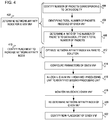
- FIG. 4 is a flow diagram illustrating a method of relocating a VNF from one processing unit to another processing until to increase a network affinity index.
- the method illustrated in FIG. 4 is executable by a network controller, such as an orchestrator to carry out operations 402-422.
- a network controller such as an orchestrator to carry out operations 402-422.
- orchestrator 104 as in FIG. 1 executes operations 402-422 to increase the network affinity index via identification of the placement of the given VNF.
- server 102 and orchestrator 104 operate in conjunction to execute operations 402-422.
- FIG. 4 is described as implemented by orchestrator 104, it may be executable on other suitable hardware components.
- FIG. 4 may be implemented in the form of executable instructions on a machine-readable storage medium 504 and 604 as in FIGS. 5-6 .
- the network controller determines the network affinity index for the given VNF.
- the network controller may proceed to operations 404-408 to identify the ratio of the number of packets by the given VNF from the data locality to the total number of packets received by that given VNF.
- Operation 402 may be similar in functionality to operation 302 as in FIG. 3 .
- the network controller identifies the number of packets received from the local cache (e.g., data locality) by the VNF over a period of time.
- the network controller monitors and counts the packets received by the VNF for the period of time from the local cache.
- the local cache is considered a memory area local to the processing unit that hosts or runs the VNF.
- the network controller identifies the number of packets from the cache remote to the processing unit. In response to identifying the number of packets from the local cache, the network controller proceeds to identify the total number of packets received over the period of time.
- the network controller identifies the total number of packets received by the VNF for the period of time. As such, at operations 404-406, the network controller monitors and counts the number of packets received by the various caches (both local and remote to the processing unit). Identifying and monitoring the packets received by the VNF enables the network controller to identify to network affinity index by calculating the ratio as at operation 408.
- the network controller determines the ratio of the number of packets from the local cache obtained at operation 404 to the total number of packets obtained at operation 406. As such the network controller calculates a value of the network affinity index by using both the number of packets identified at operation and the total number of packets at operation 408. This value indicates how efficiently the given VNF is processing packets. Using the value, the network controller identifies a relocation of the given VNF to increase the network affinity index, thus this relocation increases the operational efficiency of the given VNF to process the packets.
- the network controller identifies the placement of the given VNF such that the placement relocates the given VNF from running on one processing unit to another processing unit in the same server. Relocating the given VNF from processing units in the same server increases the network affinity index, and thus the operational efficiency of the given VNF.
- the network controller may optimize the operational efficiency of the given VNF. The operation efficiency is optimized by identifying the exact placement of the given VNF to maximize the network affinity index. This network affinity index is optimized through the use of a pareto solution as at operation 412. Operation 410 may be similar in functionality to operation 304 as in FIG. 3 .
- the network controller optimizes the network affinity index through the use of the pareto solution.
- the pareto solution is considered an optimal state of the location of the VNF to a particular processing unit in the same server. Factors that may be considered in the pareto solution includes the amount of traffic at the given VNF, the period of time, the set of VNFs the packets may be processed by, the server specification, etc. Using these factors in the pareto solution, the network controller is able to identify that processing unit among the various processing units in the same server. Identifying that processing unit, the network controller relocates the given VNF to that processing unit which most effectively processes the packets. Alternatively, this means that maximizing the relocation of the given VNF allows that given VNF to process the packets in a lesser amount of time.
- the network controller configures the parameters of a network card. Configuring the parameters sets the stage for that identified processing unit to host the given VNF.
- the network controller uses the interfaces provided by the server operating system to configure the appropriate parameters for the packet distribution function in the network card, such as the Ethernet interface.
- the network controller relocates the given VNF from the first processing unit to the second processing unit identified at operations 410-412. Operation 416 may occur simultaneously or in response to configuring the parameters of the network card as at operation 414.
- the network controller proceeds to monitor the given VNF hosted by the second processing unit (i.e., relocated processing unit). As such, the network controller monitors the given VNF to track the number of received packets which allows the network controller to re-calculate the network affinity index. Re-calculating the network affinity index over a different period of time, the network controller is able to dynamically relocate the given VNF to another processing unit. Dynamically relocating the given VNF allows that given VNF to more efficiently process the packets at different processing units over different periods of time. For example, for one period of time the given VNF may be located on one processing unit to optimize the network affinity index as the traffic pattern may vary for that one period of time. In another period of time, the VNF may be located to a different processing unit to better optimize the network affinity index.
- the network controller re-determines or re-calculates the network affinity index and as such identifies the new processing unit in which to relocate the given VNF. Identifying the new processing unit allows the network controller to dynamically select those processing unit locations within the server to optimize the network affinity index.
- FIGS. 5-6 example block diagrams of networking devices 500 and 600 with processing resources 502 and 602 are illustrated to execute machine-readable instructions in accordance with various examples of the present disclosure.
- the machine-readable instructions represent instructions that may be fetched, decoded, and/or executed by respective processing resources 502 and 602. While illustrated in a particular order, these instructions are not intended to be so limited. Rather, it is expressly contemplated that various instructions may occur in different orders and/or simultaneously with other instructions than those illustrated in FIGS. 5-6 .
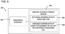
- FIG. 5 is a block diagram of networking device 500 with processing resource 502 to execute instructions 506-508 within machine-readable storage medium 504.
- networking device 500 includes processing resource 502 and machine-readable storage medium 504, it may also include other components that would be suitable to one skilled in the art.
- networking device 500 may include a controller, memory storage, or other suitable type of component.
- the networking device 500 is an electronic device with processing resource 502 capable of executing instructions 506-508 and as such embodiments of the networking device 500 include a computing device such as a server, switch, router, wireless access point (WAP), or other type of networking device or embodiments of the networking device 500 include an electronic device such as a computing device, or other type of electronic device capable of executing instructions 506-508.
- WAP wireless access point
- the instructions 506-508 may be implemented as methods, functions, operations, and other processes implemented as machine-readable instructions stored on the storage medium 504, which may be non-transitory, such as hardware storage devices (e.g., random access memory (RAM), read only memory (ROM), erasable programmable ROM, electrically erasable ROM, hard drives, and flash memory).
- RAM random access memory
- ROM read only memory
- erasable programmable ROM electrically erasable ROM
- hard drives e.g., hard drives, and flash memory
- the processing resource 502 may fetch, decode, and execute instructions 506-508 to increase a network affinity index for a given VNF. Specifically, the processing resource 502 executes instructions 506-508 to: determine for the given VNF, the network affinity index over a period of time, the network affinity index identifies a number of packets received by the VNF from a non-uniform memory access (NUMA) local to a first processing unit hosting the VNF; and increase the network affinity index via placement of the VNF from the first processing unit hosting the VNF to a second processing unit local to the NUMA.
- NUMA non-uniform memory access
- the machine-readable storage medium 504 includes instructions 506-508 for the processing resource 502 to fetch, decode, and execute.
- the machine-readable storage medium 504 may be an electronic, magnetic, optical, memory, storage, flash-drive, or other physical device that contains or stores executable instructions.
- machine-readable storage medium 504 may include, for example, Random Access Memory (RAM), an Electrically Erasable Programmable Read-Only Memory (EEPROM), a storage drive, a memory cache, network storage, a Compact Disc Read Only Memory (CDROM) and the like.
- RAM Random Access Memory
- EEPROM Electrically Erasable Programmable Read-Only Memory
- CDROM Compact Disc Read Only Memory
- machine-readable storage medium 504 may include an application and/or firmware which can be utilized independently and/or in conjunction with processing resource 502 to fetch, decode, and/or execute instructions of machine-readable storage medium 504.
- the application and/or firmware may be stored on machine-readable storage medium 504 and/or stored on another location of networking device 500.
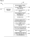
- FIG. 6 is a block diagram of networking device 600 with processing resource 602 to execute instructions 606-622 within machine-readable storage medium 604.
- networking device 600 includes processing resource 602 and machine-readable storage medium 604, it may also include other components that would be suitable to one skilled in the art.
- computing device 600 may include a controller, memory storage, or other suitable type of component.
- the networking device 600 is an electronic device with processing resource 602 capable of executing instructions 606-622 and as such embodiments of the networking device 600 include an electronic device such as a server, switch, router, wireless access point (WAP), or other type of computing device.
- WAP wireless access point
- Other embodiments of the networking device 600 include an electronic device such as a computing device, or other type of electronic device capable of executing instructions 606-622.
- the instructions 606-622 may be implemented as methods, functions, operations, and other processes implemented as machine-readable instructions stored on the storage medium 604, which may be non-transitory, such as hardware storage devices (e.g., random access memory (RAM), read only memory (ROM), erasable programmable ROM, electrically erasable ROM, hard drives, and flash memory).
- RAM random access memory
- ROM read only memory
- erasable programmable ROM electrically erasable ROM
- hard drives e.g., hard drives, and flash memory
- the processing resource 602 may fetch, decode, and execute instructions 606-622 to increase a network affinity index via placement of the VNF from one processing unit to another processing unit in closer proximity to a NUMA. Specifically, the processing resource 602 executes instructions 606-622 to: determine the network affinity index for the VNF by identifying a total number of packets received by the VNF, identifying a number of packets from a NUMA local to the processing unit hosting the VNF, and determining a ratio between number of packets from the NUMA and the total number of packets to obtain the network affinity index; increase the network affinity index via placement of the VNF from one processing unit to a different processing unit; optimize the network affinity index through use of a pareto solution that indicates the optimal location or placement of the VNF; monitor the VNF placement of the different processing unit; redetermine a new network affinity index for a different period of time; and transition the VNF from the different processing unit to another processing unit (e.g., third processing unit).
- the processing resource 602 executes instructions 606
- the machine-readable storage medium 604 includes instructions 606-622 for the processing resource 602 to fetch, decode, and execute.
- the machine-readable storage medium 604 may be an electronic, magnetic, optical, memory, storage, flash-drive, or other physical device that contains or stores executable instructions.
- machine-readable storage medium 604 may include, for example, Random Access Memory (RAM), an Electrically Erasable Programmable Read-Only Memory (EEPROM), a storage drive, a memory cache, network storage, a Compact Disc Read Only Memory (CDROM) and the like.
- RAM Random Access Memory
- EEPROM Electrically Erasable Programmable Read-Only Memory
- CDROM Compact Disc Read Only Memory
- machine-readable storage medium 604 may include an application and/or firmware which can be utilized independently and/or in conjunction with processing resource 502 to fetch, decode, and/or execute instructions of machine-readable storage medium 604.
- the application and/or firmware may be stored on machine-readable storage medium 604 and/or stored on another location of networking device 600.
- An example non-transitory machine-readable storage medium comprises instructions that when executed by a processing resource cause a networking device to:
Landscapes
- Engineering & Computer Science (AREA)
- Computer Networks & Wireless Communication (AREA)
- Signal Processing (AREA)
- Computer Security & Cryptography (AREA)
- Environmental & Geological Engineering (AREA)
- Data Exchanges In Wide-Area Networks (AREA)
Abstract
Description
- Network Functions Virtualization (NFV) involves replacing expensive and inflexible network hardware with network services that operate virtually on commodity hardware. NFV increases resource efficiency usage and deployment of new services in a network. The deployment of these new services within the NFV system refers to the implementation of virtualized network functions (VNFs) using software decoupled from the underlying hardware. The VNFs are responsible for handling specific network functions that run on a virtual machine in the NFV system.
- In the accompanying drawings, like numerals refer to like components or blocks. The following detailed description references the drawings, wherein:
-
FIG. 1 illustrates an example server including an orchestrator to increase a network affinity index via placement of a VNF from one memory zone to another memory zone in accordance with the present disclosure; -
FIGS. 2A-2B illustrate an example server to reposition a VNF to optimize placement in accordance with the present disclosure; -
FIG. 3 illustrates an example flow diagram to identify placement of a VNF to increase a network affinity index in accordance with the present disclosure; -
FIG. 4 illustrates an example flow diagram to optimize a network affinity index via placement of a VNF from one processing unit to another processing unit in accordance with the present disclosure; -
FIG. 5 is a block diagram of an example computing device with a processing resource to execute instructions in a machine-readable storage medium for increasing a network affinity index via placement of a VNF from one processing unit to another processing unit in accordance with the present disclosure; and -
FIG. 6 is a block diagram of an example computing device with a processing resource to execute instructions in a machine-readable storage medium for determining a network affinity index for a given VNF via identification of a total number of packets received by the given VNF and a number of packets from a memory zone local to a processing unit in accordance with the present disclosure. - Virtualized network functions (VNFs) as described herein, includes those network functions and/or network services that are performed in a virtualized manner. Accordingly, VNFs are considered network functions which may have formerly been executed on dedicated hardware. The VNFs are those virtualized tasks in which a service carrier injects a service and/or function between nodes during packet transportation. VNFs include, by way of example, internal tracking, load balancer, firewalls, network address translation, inspection, deep packet inspection (DPI), encryption, decryption, quality of service (QoS), network forwarding policy, layer 4-7 switching, IP forwarding, virtual LAN switching, among many others.
- To perform packet processing and VNF execution within the NFV system, packets are rerouted to those networking devices that host the VNFs. Rerouting the packets to those network devices hosting the VNFs may introduce much latency and errors as the NFV system may include architectural limitations. For example, upon receiving a packet in by a processor in one memory zone, a controller may copy the packet to another memory zone associated with another processor hosting the VNF. Copying the packet over to the different memory zone associated with the different processor ensures the packet is properly routed but introduces overhead. The overhead includes increasing latency and decreasing the overall efficiency in the network system. As such, due to the architecture limitations and rerouting packets, the NFV system may not be optimized for high-speed packet processing.
- The present disclosure provides a controller that optimizes placement of the VNF on a specific core within service such that the placement reduces the copying of packets between the various memory zones. Reducing the copying of the packets between the memory zones also reduces the processing latency associated with the packet processing. The controller calculates a memory zone efficiency and based on this calculation, the controller identify a different placement for the VNF that increases the memory zone efficiency.
- The following detailed description refers to the accompanying drawings. Wherever possible, the same reference numbers are used in the drawings and the following description to refer to the same or similar parts. It is to be expressly understood, however, that the drawings are for the purpose of illustration and description only. While several examples are described in this document, modifications, adaptations, and other implementations are possible. Accordingly, the following detailed description does not limit the disclosed examples. Instead, the proper scope of the disclosed examples may be defined by the appended claims.
- The terminology used herein is for the purpose of describing particular embodiments only and is not intended to be limiting. As used herein, the singular forms "a," "an," and "the" are intended to include the plural forms as well, unless the context clearly indicates otherwise. The term "multiple," as used herein, is defined as two, or more than two. The term "another," as used herein, is defined as at least a second or more. The term "coupled," as used herein, is defined as connected, whether directly without any intervening elements or indirectly with at least one intervening elements, unless otherwise indicated. Two elements can be coupled mechanically, electrically, or communicatively linked through a communication channel, pathway, network, or system. The term "and/or" as used herein refers to and encompasses any and all possible combinations of one or more of the associated listed items. It will also be understood that, although the terms first, second, third, etc. may be used herein to describe various elements, these elements should not be limited by these terms, as these terms are only used to distinguish one element from another unless stated otherwise or the context indicates otherwise. As used herein, the term "includes" means includes but not limited to, the term "including" means including but not limited to. The term "based on" means based at least in part on.
- The foregoing disclosure describes a number of example implementations for identifying a placement of a virtualized network function (VNF) to increase a network affinity index. The disclosed examples may include systems, devices, computer-readable storage media, and methods for increasing the network affinity index. For purposes of explanation, certain examples are described with reference to the components illustrated in
FIGS. 1-6 . The functionality of the illustrated components may overlap, however, and may be present in a fewer or greater number of elements and components. Further, all or part of the functionality of illustrated elements may coexist or be distributed among several geographically dispersed locations. Moreover, the disclosed examples may be implemented in various environments and are not limited to the illustrated examples. -
FIG. 1 illustrates anexample server 102 to receivepacket 104 and providing tomemory zones 106a-106b. Memory zones 106-106b includememory cores 108a-108b which allocaterespective processing units 110a-110d to hostcorresponding VNFs 112a-112d. Orchestrator 114 operates in conjunction withserver 102 to determine a network affinity index for a given VNF amongVNFs 112a-1 12d and in turn, identifies a placement for the given VNF amongprocessing units 110a-110d to increase the network affinity index. The network affinity index is a measure of efficiency for the given VNF. Measuring the network affinity index,orchestrator 114 may relocate the given VNF amongprocessing units 110a-110d inserver 102.Server 102 includes a computing device such as a database server, mail server, file server, domain name system (DNS) server, print server, web server, game server, application server, telecommunications server, cartridge server, blade server, catalog server, communication server, home server, media server, proxy server, or other type of computing device capable of receiving packets and performing network function services atprocessing unit 110a-110d. AlthoughFIG. 1 illustratesserver 102,memory zones 106a-106b, andorchestrator 114, implementations should not be limited as this was done for illustration purposes. For example,FIG. 1 may include a network card that receivespacket 104 for queueing to aparticular processing unit 110a-110d to be processed by a given VNF 112a-112d. This implementation is explained in detail in a later figure. - To provide more context over
FIG. 1 , assume packets from a network card (not illustrated) are delivered to theparticular processing unit 110b (vCPU 1) which belongs tomemory core 108a (Core 0) inmemory zone 106a (Memory Zone 1). Assume the packets may be routed for servicing to VNF 112c (VNF 2) located inmemory zone 106b (Memory Zone 2), thus the packets may be copied between to thememory zones 106a -106b. The copying betweenmemory zones 106a-106b increase latency and overall efficiency. To combat these efficiency issues,orchestrator 114 determines the network affinity index for a given VNF and identifies where to relocate the given VNF so the packets arrive on theprocessing unit 110a-110d in thememory zone 106a-106b hosting the given VNF. Taking into account the network affinity index optimizes the location of the given VNF to thedifferent processing units 110a-110d such that the memory zone in closer proximity to the processing unit hosting the given VNF and thus increases the overall efficiency. -
Memory zones 106a-106b represent the caching architecture ofserver 102. As such,memory zones 106a-106b may comprise non-uniform memory access (NUMA) zones where the access to a given VNF amongVNFs 112a-112d depends on the memory location relative toprocessing units 110a-110d. Within eachmemory zone 106a-106b includescores 108a-108b that may queue packets for processingunits 110a-110d that are hosting givenVNFs 112a-112d. In implementations,memory zones 106a-106b are memory locations internal toserver 102 that queue packets for assigning toparticular processing units 110a-110d depending on whichVNF 112a-112d is to service the packets. Accordingly,memory zones 106a-106b include a data locality, NUMA, memory partition, and/or memory location. -
Memory cores 108a-108b are units that read and execute a set of instructions to configureprocessing units 110a-110d to hostVNFs 112a-112d. In implementations,memory cores 108a-108b may also include local cache (not illustrated) and represent a set of multiple cores.Memory cores 108a-108b may be similar in structure and functionality to each other and as such, embodiments ofmemory cores 108a-108b include an execution unit, processing unit, processing node, executing node, or other type of unit capable of queuing packets to a particular processing unit amongprocessing unit 110a-110d hosting the given VNF. -
Processing units 110a-110d represent the various components internal toserver 102 that hosts at least one of theVNFs 112a-112d. In this manner, theprocessing units 110a-110d each correspond to the various VNFs 112a-112d. For example, processingunit 110a corresponds toVNF 112a, processingunit 110b corresponds toVNF 112b and so on. In another implementation,processing units 110a-110d comprise virtualized components to hostVNFs 112a-112d. In this implementation, eachprocessing unit 110a-110d comprises a virtualized central processing unit that are assigned to virtual machines to host the particular VNF. Yet in a further implementation,processing units 110a-110d may represent the virtualmachines hosting VNFs 112a-112d. - VNFs 112a-112d each represent a specific network function that is hosted by
processing units 110a-110d within eachmemory zone 106a-106b. In one implementation, eachVNF 112a-112d represents a different network function that may process packets. In this implementation,memory cores 108a-108b queue the packets at thespecific processing unit 1 10a-1 10d hosting that particular network function. For example,VNF 112a may perform QoS,VNF 112b perform DPI,VNF 112c perform internal tracking, andVNF 112d perform VLAN switching. -
Orchestrator 114 measures the network affinity index to identify an optimal placement among processingunits 110a-110d for the given VNF as at modules 116-118. AlthoughFIG. 1 illustratesorchestrator 114 as internal toserver 102, this was done for illustration purposes asorchestrator 114 may be located externally toserver 102. Implementations oforchestrator 114 include, electronic circuitry (i.e., hardware) that implements the functionality of modules 116-118, such an integrated circuit, programmable circuit, application integrated circuit (ASIC), controller, processor, semiconductor, processing resource, chipset, or other type of hardware component capable of the functionality of modules 116-118. Alternatively,orchestrator 114 may include instructions (e.g., stored on a machine-readable medium) that, when executed by a hardware component (e.g., controller and/or processor) determines the network affinity index and repositions the corresponding VNF, accordingly. - At modules 116-118,
orchestrator 114 determines the network affinity index for the given VNF. Based on the network affinity index,orchestrator 114 identifies an optimal placement for the given VNF among processingunits 110a-110d. In one implementation, the network affinity index is a ratio of the total number of packets received by the given VNF from the particular processing unit hosting that given VNF to the total number of packets received by the VNF over a period of time. Thus,orchestrator 114 may relocate the given VNF. In a further implementation,orchestrator 114 performs a pareto solution to relocate the given VNF to an optimal placement among processingunits 110a-110d, Modules 116-118 may include, by way of example, instructions (e.g., stored on a machine-readable medium) that, when executed (e.g., by orchestrator 114), implements the functionality of module 116-118. Alternatively, or in addition, modules 116-118 may include electronic circuitry (i.e., hardware) that implements the corresponding functionality. -
FIG. 2A illustrates a network to distribute traffic, e.g.,packets 104 toserver 102. Based on receivingpackets 104 byserver 102, an Ethernet interface distributes thepackets 104 toqueues 216a-216.Processing units 110a-110d retrieve thepackets 104 fromqueues 216a-216c for processing byVNFs 112a-1 12d.Orchestrator 114 determines a network affinity index for eachVNF 112a-1 12d at various numbered positions in the networking system. The various numbered positions will be explained in detail later in the figure. - The Ethernet interface receives the incoming packets and distributes the packets to
queues 216a-216c based on a hashing algorithm. The hashing algorithm allowsorchestrator 114 to determine whichqueue 216a-216c to place the packet based on where the packets are being transmitted from. The traffic distribution results in specific packets to queue assignment. As such, to optimize the queue assignment,orchestrator 114 proceeds to optimize the network affinity index. - To identify the placement of the given VNF,
orchestrator 114 may measure the network affinity index at various positions in a networking system. Each of the placements within the networking system is analyzed to configure the optimal packet processing. For example, at (1) the Ethernet interface, the packets are distributed toqueues 216a-216c based on source and/or destination header info from each packet. The packets are distributed toqueues 216a-216c for processing atvarious processing unit 1 10a-110d hosting VNFs 112a-112d. At placement (2), each of thequeues 216a-216c is handled by processingunits 110a-110d.Processing units 110a-110d retrieves the packets from queue configured to optimize packet handling. At placement (3) VNFs 112a-112d are assigned to one ormore processing units 110a-110d based on the packet processing path configuration. - At each of these points,
orchestrator 114 may determine network affinity index value. In one implementation, the network affinity index value is measurement over a time period expressing the efficiency of a given VNF. In this implementation, the network affinity index includes a ratio including the number of packet received from a local cache at a particular processing unit to the overall total number of packets received by the VNF. Based on the network affinity index value,orchestrator 114 may proceed to identify an optimal placement of the given VNF among processingunits 110a-110d. The optimal placement may be dependent on a number of factors in addition to the network affinity index. The factors may include collected performance metrics of each ofVNFs 112a-112d, databased information, configuration information, an admin may choose to add ontoserver 102, and/other parameters. Using these number of factors and the network affinity index,orchestrator 114 may calculate pareto solution to identify the optimal placement of the given VNF. -
FIG. 2B illustrates anexample orchestrator 114 to identify an optimal VNF placement based on a network affinity index value (NEI). To calculate the NEI and select the appropriate processing unit for a given VNF execution, there are various factors that may be considered byorchestrator 114. One such factor may include the set of VNFs that may be used for packet processing, while another factor may include traffic distribution. For example, traffic distribution may change overtime, as such the placement of the given VNF may change as traffic changes over time. For example, a different time of day may change the access patterns to VNFs at different geographical locations. As such,orchestrator 114 may select the appropriate processing unit for the given VNF execution. - To select the optimal processing unit for that given VNF, an optimization formula may be used as indicated the optimizer. The optimizer may use specialized solvers including, but not limited to, Gurobi, CPLEX, etc. In this manner, the NEI may be maximized for each of the VNFs.
- In response to identifying the appropriate processing unit for the given VNF execution,
orchestrator 114 may proceed to configure the interfaces and parameters for that appropriate processing unit. Upon configuring the appropriate processing unit,orchestrator 114 continues to monitor each VNF for changes or modifications in the VNF environment. This allows orchestrator 114 to continually monitor and re-locate the given VNF to the most optimal processing unit over time. - Referring now to
FIGS. 3 and4 , flow diagrams are illustrated in accordance with various examples of the present disclosure. The flow diagrams represent processes that may be utilized in conjunction with various systems and devices as discussed with reference to the preceding figures. While illustrated in a particular order, the flow diagrams are not intended to be so limited. Rather, it is expressly contemplated that various processes may occur in different orders and/or simultaneously with other processes than those illustrated. As such, the sequence of operations described in connection withFIGS. 3-4 are examples and are not intended to be limiting. Additional or fewer operations or combinations of operations may be used or may vary without departing from the scope of the disclosed examples. Thus, the present disclosure merely sets forth possible examples of implementations, and many variations and modifications may be made to the described examples. -
FIG. 3 is a flow diagram illustrating a method of executable by a network controller to identify a placement of a VNF for increasing a network affinity index. The flow diagram may initially determine the network affinity index for a given VNF. The network affinity index may be calculated based on a number of packets received by the VNF from a specific data locality over a total number of packets received by the VNF. In discussingFIG. 3 , references may be made to the components inFIGS. 1-2B to provide contextual examples. In one implementation,orchestrator 104 as inFIG. 1 executes operations 302-304 to increase the network affinity index via identification of the placement of the given VNF. In another implementation,server 102 andorchestrator 104 operate in conjunction to execute operations 302-304. AlthoughFIG. 3 is described as implemented byorchestrator 104, it may be executable on other suitable hardware components. For example,FIG. 3 may be implemented in the form of executable instructions on a machine-readable storage medium FIGS. 5-6 . - At
operation 302, the network controller determines the network affinity index for a given VNF over a period of time. The network affinity index indicates the efficiency for the given VNF. As such, in implementations, the network affinity index is calculated as the number of packets the given VNF receives from a local processing cache (e.g., data locality) over the total number of packets received by the given VNF. This may include identifying the number of packets from the data locality in proximity to the processing unit hosting the given VNF. This implementation is discussed in detail in later figures. In other implementations, the network affinity index is calculated according to the number of packets received by the given VNF from the data locality remote to the processing unit hosting the given VNF over the total of number of packets received by the given VNF. Yet in further implementations, a different weighting value is placed on the number of packets received by the given VNF from the data locality remote to the processing unit compares to the number of packets from the data area local to the processing unit. In identifying the number of packets from the data locality remote to the processing unit or local to the processing unit, the network controller proceeds to calculate the ration between the number of packets to the overall total number of packets received. - At
operation 304 in response to determining the network affinity index, the network controller identifies the placement of the given VNF. At this operation, the network controller proceeds to relocate the VNF from the one processing unit hosting the VNF to another processing unit in closer proximity to the data locality. Identifying and relocating the VNF to the other processing unit increases the network affinity index such that a greater number of packets are received by the given VNF from the local processing unit cache. This allows the given VNF to operate in greater efficiency for processing a higher number of packets. Both processing units are located within the server such that the relocation also occurs within the same server. Although the identification of the placement of the VNF is considered extrinsic to the processing unit currently hosting the given VNF, the newly identified placement is still located within the same server. Identifying the placement of the given VNF maximizes the data locality for that VNF. Upon identifying the placement of the given VNF, the network controller proceeds to configure the parameters of the VNF to relocate to the different processing unit within the same server. -
FIG. 4 is a flow diagram illustrating a method of relocating a VNF from one processing unit to another processing until to increase a network affinity index. The method illustrated inFIG. 4 is executable by a network controller, such as an orchestrator to carry out operations 402-422. In discussingFIG. 4 , references may be made to the components inFIGS. 1-2B to provide contextual examples. In one implementation,orchestrator 104 as inFIG. 1 executes operations 402-422 to increase the network affinity index via identification of the placement of the given VNF. In another implementation,server 102 andorchestrator 104 operate in conjunction to execute operations 402-422. AlthoughFIG. 4 is described as implemented byorchestrator 104, it may be executable on other suitable hardware components. For example,FIG. 4 may be implemented in the form of executable instructions on a machine-readable storage medium FIGS. 5-6 . - At
operation 402, the network controller determines the network affinity index for the given VNF. In this implementation, the network controller may proceed to operations 404-408 to identify the ratio of the number of packets by the given VNF from the data locality to the total number of packets received by that given VNF.Operation 402 may be similar in functionality tooperation 302 as inFIG. 3 . - At
operation 404, the network controller identifies the number of packets received from the local cache (e.g., data locality) by the VNF over a period of time. In this implementation, the network controller monitors and counts the packets received by the VNF for the period of time from the local cache. The local cache is considered a memory area local to the processing unit that hosts or runs the VNF. In an implementation rather than identifying the number of packets received from the local cache, the network controller identifies the number of packets from the cache remote to the processing unit. In response to identifying the number of packets from the local cache, the network controller proceeds to identify the total number of packets received over the period of time. - At
operation 406, the network controller identifies the total number of packets received by the VNF for the period of time. As such, at operations 404-406, the network controller monitors and counts the number of packets received by the various caches (both local and remote to the processing unit). Identifying and monitoring the packets received by the VNF enables the network controller to identify to network affinity index by calculating the ratio as atoperation 408. - At
operation 408, the network controller determines the ratio of the number of packets from the local cache obtained atoperation 404 to the total number of packets obtained atoperation 406. As such the network controller calculates a value of the network affinity index by using both the number of packets identified at operation and the total number of packets atoperation 408. This value indicates how efficiently the given VNF is processing packets. Using the value, the network controller identifies a relocation of the given VNF to increase the network affinity index, thus this relocation increases the operational efficiency of the given VNF to process the packets. - At
operation 410, the network controller identifies the placement of the given VNF such that the placement relocates the given VNF from running on one processing unit to another processing unit in the same server. Relocating the given VNF from processing units in the same server increases the network affinity index, and thus the operational efficiency of the given VNF. In a further implementation, the network controller may optimize the operational efficiency of the given VNF. The operation efficiency is optimized by identifying the exact placement of the given VNF to maximize the network affinity index. This network affinity index is optimized through the use of a pareto solution as atoperation 412.Operation 410 may be similar in functionality tooperation 304 as inFIG. 3 . - At
operation 412, the network controller optimizes the network affinity index through the use of the pareto solution. The pareto solution is considered an optimal state of the location of the VNF to a particular processing unit in the same server. Factors that may be considered in the pareto solution includes the amount of traffic at the given VNF, the period of time, the set of VNFs the packets may be processed by, the server specification, etc. Using these factors in the pareto solution, the network controller is able to identify that processing unit among the various processing units in the same server. Identifying that processing unit, the network controller relocates the given VNF to that processing unit which most effectively processes the packets. Alternatively, this means that maximizing the relocation of the given VNF allows that given VNF to process the packets in a lesser amount of time. - At
operation 414 in response to identifying the placement that increase the network affinity index, the network controller configures the parameters of a network card. Configuring the parameters sets the stage for that identified processing unit to host the given VNF. In another implementation upon identifying the optimal location for the given VNF in the server as atoperation 412, the network controller uses the interfaces provided by the server operating system to configure the appropriate parameters for the packet distribution function in the network card, such as the Ethernet interface. - At
operation 416, the network controller relocates the given VNF from the first processing unit to the second processing unit identified at operations 410-412.Operation 416 may occur simultaneously or in response to configuring the parameters of the network card as atoperation 414. - At
operation 418, the network controller proceeds to monitor the given VNF hosted by the second processing unit (i.e., relocated processing unit). As such, the network controller monitors the given VNF to track the number of received packets which allows the network controller to re-calculate the network affinity index. Re-calculating the network affinity index over a different period of time, the network controller is able to dynamically relocate the given VNF to another processing unit. Dynamically relocating the given VNF allows that given VNF to more efficiently process the packets at different processing units over different periods of time. For example, for one period of time the given VNF may be located on one processing unit to optimize the network affinity index as the traffic pattern may vary for that one period of time. In another period of time, the VNF may be located to a different processing unit to better optimize the network affinity index. - At operations 420-422, the network controller re-determines or re-calculates the network affinity index and as such identifies the new processing unit in which to relocate the given VNF. Identifying the new processing unit allows the network controller to dynamically select those processing unit locations within the server to optimize the network affinity index.
- Referring now to
FIGS. 5-6 , example block diagrams ofnetworking devices processing resources respective processing resources FIGS. 5-6 . -
FIG. 5 is a block diagram ofnetworking device 500 withprocessing resource 502 to execute instructions 506-508 within machine-readable storage medium 504. Althoughnetworking device 500 includesprocessing resource 502 and machine-readable storage medium 504, it may also include other components that would be suitable to one skilled in the art. For example,networking device 500 may include a controller, memory storage, or other suitable type of component. Thenetworking device 500 is an electronic device withprocessing resource 502 capable of executing instructions 506-508 and as such embodiments of thenetworking device 500 include a computing device such as a server, switch, router, wireless access point (WAP), or other type of networking device or embodiments of thenetworking device 500 include an electronic device such as a computing device, or other type of electronic device capable of executing instructions 506-508. The instructions 506-508 may be implemented as methods, functions, operations, and other processes implemented as machine-readable instructions stored on thestorage medium 504, which may be non-transitory, such as hardware storage devices (e.g., random access memory (RAM), read only memory (ROM), erasable programmable ROM, electrically erasable ROM, hard drives, and flash memory). - The
processing resource 502 may fetch, decode, and execute instructions 506-508 to increase a network affinity index for a given VNF. Specifically, theprocessing resource 502 executes instructions 506-508 to: determine for the given VNF, the network affinity index over a period of time, the network affinity index identifies a number of packets received by the VNF from a non-uniform memory access (NUMA) local to a first processing unit hosting the VNF; and increase the network affinity index via placement of the VNF from the first processing unit hosting the VNF to a second processing unit local to the NUMA. - The machine-
readable storage medium 504 includes instructions 506-508 for theprocessing resource 502 to fetch, decode, and execute. In another embodiment, the machine-readable storage medium 504 may be an electronic, magnetic, optical, memory, storage, flash-drive, or other physical device that contains or stores executable instructions. Thus, machine-readable storage medium 504 may include, for example, Random Access Memory (RAM), an Electrically Erasable Programmable Read-Only Memory (EEPROM), a storage drive, a memory cache, network storage, a Compact Disc Read Only Memory (CDROM) and the like. As such, machine-readable storage medium 504 may include an application and/or firmware which can be utilized independently and/or in conjunction withprocessing resource 502 to fetch, decode, and/or execute instructions of machine-readable storage medium 504. The application and/or firmware may be stored on machine-readable storage medium 504 and/or stored on another location of networkingdevice 500. -
FIG. 6 is a block diagram ofnetworking device 600 withprocessing resource 602 to execute instructions 606-622 within machine-readable storage medium 604. Althoughnetworking device 600 includesprocessing resource 602 and machine-readable storage medium 604, it may also include other components that would be suitable to one skilled in the art. For example,computing device 600 may include a controller, memory storage, or other suitable type of component. Thenetworking device 600 is an electronic device withprocessing resource 602 capable of executing instructions 606-622 and as such embodiments of thenetworking device 600 include an electronic device such as a server, switch, router, wireless access point (WAP), or other type of computing device. Other embodiments of thenetworking device 600 include an electronic device such as a computing device, or other type of electronic device capable of executing instructions 606-622. The instructions 606-622 may be implemented as methods, functions, operations, and other processes implemented as machine-readable instructions stored on thestorage medium 604, which may be non-transitory, such as hardware storage devices (e.g., random access memory (RAM), read only memory (ROM), erasable programmable ROM, electrically erasable ROM, hard drives, and flash memory). - The
processing resource 602 may fetch, decode, and execute instructions 606-622 to increase a network affinity index via placement of the VNF from one processing unit to another processing unit in closer proximity to a NUMA. Specifically, theprocessing resource 602 executes instructions 606-622 to: determine the network affinity index for the VNF by identifying a total number of packets received by the VNF, identifying a number of packets from a NUMA local to the processing unit hosting the VNF, and determining a ratio between number of packets from the NUMA and the total number of packets to obtain the network affinity index; increase the network affinity index via placement of the VNF from one processing unit to a different processing unit; optimize the network affinity index through use of a pareto solution that indicates the optimal location or placement of the VNF; monitor the VNF placement of the different processing unit; redetermine a new network affinity index for a different period of time; and transition the VNF from the different processing unit to another processing unit (e.g., third processing unit). - The machine-
readable storage medium 604 includes instructions 606-622 for theprocessing resource 602 to fetch, decode, and execute. In another embodiment, the machine-readable storage medium 604 may be an electronic, magnetic, optical, memory, storage, flash-drive, or other physical device that contains or stores executable instructions. Thus, machine-readable storage medium 604 may include, for example, Random Access Memory (RAM), an Electrically Erasable Programmable Read-Only Memory (EEPROM), a storage drive, a memory cache, network storage, a Compact Disc Read Only Memory (CDROM) and the like. As such, machine-readable storage medium 604 may include an application and/or firmware which can be utilized independently and/or in conjunction withprocessing resource 502 to fetch, decode, and/or execute instructions of machine-readable storage medium 604. The application and/or firmware may be stored on machine-readable storage medium 604 and/or stored on another location of networkingdevice 600. - An example non-transitory machine-readable storage medium according to this disclosure comprises instructions that when executed by a processing resource cause a networking device to:
- determine, for a virtualized network function (VNF), a network affinity index over a period of time that identifies a number of packets received by the VNF from a non-uniform memory access (NUMA) local to a first processing unit hosting the VNF; and
- increase the network affinity index via placement of the VNF from the first processing unit to a second processing unit local to the NUMA.
- identifying a total number of packets received by the VNF;
- identifying the number of packets received by the VNF from the NUMA local to the first processing unit; and
- determining a ratio of the number of packet received from the NUMA over the total number of packets.
- adjust the network affinity index over a different period of time corresponding to the number of packets received by the VNF from a different NUMA; and
- based on the adjusted network affinity index, transition the VNF from the second processing unit to a third processing unit local to the different NUMA.
- Although certain embodiments have been illustrated and described herein, it will be greatly appreciated by those of ordinary skill in the art that a wide variety of alternate and/or equivalent embodiments or implementations calculated to achieve the same purposes may be substituted for the embodiments shown and described without departing from the scope of this disclosure. Those with skill in the art will readily appreciate that embodiments may be implemented in a variety of ways. This application is intended to cover adaptions or variations of the embodiments discussed herein. Therefore, it is manifestly intended that embodiments be limited only by the claims and equivalents thereof.
A further example non-transitory machine-readable storage medium according to this disclosure comprises instructions that when executed by the processing resource cause the computing device to:
A further example non-transitory machine-readable storage medium according to this disclosure is such that to increase the network affinity index comprises instructions that when executed by the processing resource cause the networking device to optimize the network affinity index via a pareto solution.
Claims (15)
- A method, executable by a network controller, the method comprising:determining, for a virtualized a network function (VNF), a network affinity index over a period of time that identifies a number of packets received by the VNF from a data locality corresponding to a processing unit hosting the VNF; andidentifying a placement of the VNF extrinsic to the processing unit hosting the VNF to increase the network affinity index.
- The method of claim 1 wherein determining, for the VNF, the network affinity index comprises:identifying a total number of packets received by the VNF over the period of time; andidentifying the number of packets received by the VNF that corresponds to the data locality local to the processing unit hosting the VNF; anddetermining a ratio of the number of packets over the total number of packets.
- The method of claim 1 comprising:
placing the number of packets in the data locality corresponding to the processing unit hosting the VNF. - The method of claim 1 comprising:
re-determining the network affinity index for the VNF over a different period of time. - The method of claim 1 wherein identifying the placement of the VNF to increase the network affinity index comprises:
optimizing the network efficiency index via identification of a processing unit local to the data locality to host the VNF. - The method of claim 1 wherein identifying the placement of the VNF to increase the network affinity index comprises:
relocating the VNF from the processing unit hosting the VNF to a different processing unit local to the data locality. - The method of claim 6 wherein the processing unit and the different processing unit are located within a same server.
- The method of claim 7 comprising:
configuring parameters of the VNF via an Ethernet interface to place the VNF from the processing unit to the different processing unit. - The method of claim 1 wherein the placement of the VNF to increase the network affinity index at an expense to other VNFs.
- A system comprising a server and including
a set of VNFs located on processing units in the server;
an orchestrator to:for each VNF, determine a network affinity index that identifies a number of packets received by a given VNF from a memory zone local to one of the processing units hosting the given VNF; andincrease the network affinity index via identification of a placement of the given VNF from the one of the processing units hosting the given VNF to a different processing unit among the processing units closer in proximity to the memory zone. - The system of claim 10 comprising:
the processing units to host the set of VNFs. - The system of claim 11 wherein the orchestrator proceeds to increase the network affinity index for each of the VNFs via relocation of each of the VNFs from a processing unit among the processing units to a different processing unit among the processing unit.
- The system of claim 10 wherein for each VNF to determine the network affinity index for the given VNF, the orchestrator is to:determine a total number of packets received by the given VNF;determine a number of packets received by the given VNF corresponding to the memory zone; anddetermine a ratio of the number of packets over the total number of packets.
- The system of claim 10 comprising:
an optimizer to optimize the network affinity index via a pareto solution. - A non-transitory machine-readable storage medium comprising instructions that when executed by a processing resource cause a networking device to operate according to the method of any of claims 1 to 9.
Applications Claiming Priority (1)
| Application Number | Priority Date | Filing Date | Title |
|---|---|---|---|
| US15/611,095 US10728132B2 (en) | 2017-06-01 | 2017-06-01 | Network affinity index increase |
Publications (2)
| Publication Number | Publication Date |
|---|---|
| EP3410638A1 true EP3410638A1 (en) | 2018-12-05 |
| EP3410638B1 EP3410638B1 (en) | 2021-03-03 |
Family
ID=62630902
Family Applications (1)
| Application Number | Title | Priority Date | Filing Date |
|---|---|---|---|
| EP18174546.4A Active EP3410638B1 (en) | 2017-06-01 | 2018-05-28 | Network affinity index increase |
Country Status (2)
| Country | Link |
|---|---|
| US (1) | US10728132B2 (en) |
| EP (1) | EP3410638B1 (en) |
Families Citing this family (2)
| Publication number | Priority date | Publication date | Assignee | Title |
|---|---|---|---|---|
| US10432524B2 (en) * | 2017-12-20 | 2019-10-01 | At&T Intellectual Property I, L.P. | Parallelism for virtual network functions in service function chains |
| CN114641024B (en) * | 2020-12-15 | 2024-12-10 | 中国电信股份有限公司 | Method and device for determining resource utilization rate of network function network element |
Citations (1)
| Publication number | Priority date | Publication date | Assignee | Title |
|---|---|---|---|---|
| US20150326535A1 (en) * | 2014-05-07 | 2015-11-12 | Verizon Patent And Licensing Inc. | Network platform-as-a-service for creating and inserting virtual network functions into a service provider network |
Family Cites Families (71)
| Publication number | Priority date | Publication date | Assignee | Title |
|---|---|---|---|---|
| US9213732B2 (en) * | 2012-12-28 | 2015-12-15 | Sap Ag | Hash table and radix sort based aggregation |
| EP2849064B1 (en) | 2013-09-13 | 2016-12-14 | NTT DOCOMO, Inc. | Method and apparatus for network virtualization |
| US9936047B2 (en) * | 2013-10-17 | 2018-04-03 | Ciena Corporation | Method and apparatus for provisioning virtual network functions from a network service provider |
| US20150124622A1 (en) * | 2013-11-01 | 2015-05-07 | Movik Networks, Inc. | Multi-Interface, Multi-Layer State-full Load Balancer For RAN-Analytics Deployments In Multi-Chassis, Cloud And Virtual Server Environments |
| US9363180B2 (en) * | 2013-11-04 | 2016-06-07 | Telefonkatiebolaget L M Ericsson (Publ) | Service chaining in a cloud environment using Software Defined Networking |
| US9384028B1 (en) | 2013-12-19 | 2016-07-05 | Amdocs Software Systems Limited | System, method, and computer program for preserving service continuity in a network function virtualization (NFV) based communication network |
| US10069694B1 (en) * | 2016-07-28 | 2018-09-04 | Amdocs Development Limited | System, method, and computer program for automatically certifying a virtual network function (VNF) for use in a network function virtualization (NFV) based communication network |
| EP3089031A4 (en) * | 2013-12-27 | 2017-01-04 | NTT Docomo, Inc. | Management system, virtual communication-function management node, and management method |
| US9520961B2 (en) * | 2014-01-17 | 2016-12-13 | Telefonaktiebolaget L M Ericsson (Publ) | System and methods for optical lambda flow steering |
| US9948493B2 (en) * | 2014-04-03 | 2018-04-17 | Centurylink Intellectual Property Llc | Network functions virtualization interconnection gateway |
| US10445339B1 (en) * | 2014-05-28 | 2019-10-15 | EMC IP Holding Company LLC | Distributed contextual analytics |
| US20150355946A1 (en) * | 2014-06-10 | 2015-12-10 | Dan-Chyi Kang | “Systems of System” and method for Virtualization and Cloud Computing System |
| US9742690B2 (en) * | 2014-08-20 | 2017-08-22 | At&T Intellectual Property I, L.P. | Load adaptation architecture framework for orchestrating and managing services in a cloud computing system |
| US9800673B2 (en) * | 2014-08-20 | 2017-10-24 | At&T Intellectual Property I, L.P. | Service compiler component and service controller for open systems interconnection layer 4 through layer 7 services in a cloud computing system |
| WO2016029974A1 (en) * | 2014-08-29 | 2016-03-03 | Nec Europe Ltd. | Method for operating a virtual network infrastructure |
| US9558041B2 (en) * | 2014-09-05 | 2017-01-31 | Telefonaktiebolaget L M Ericsson (Publ) | Transparent non-uniform memory access (NUMA) awareness |
| WO2016048430A1 (en) * | 2014-09-25 | 2016-03-31 | Intel IP Corporation | Network functions virtualization |
| US9489242B2 (en) * | 2014-09-30 | 2016-11-08 | Telefonaktiebolaget L M Ericsson (Publ) | Algorithm for faster convergence through affinity override |
| CN105528234A (en) * | 2014-10-24 | 2016-04-27 | 中兴通讯股份有限公司 | Virtual machine migration processing method and device |
| US9729396B2 (en) * | 2014-11-04 | 2017-08-08 | Cisco Technology, Inc. | System and method for providing dynamic radio access network orchestration |
| NL2013746B1 (en) * | 2014-11-05 | 2016-10-06 | MCI (Mirror Controls International) Netherlands B V | Exterior mirror unit. |
| US10091058B2 (en) * | 2014-11-10 | 2018-10-02 | Futurewei Technologies, Inc. | Method and apparatus for model-driven, affinity-based, network functions |
| CN104410672B (en) * | 2014-11-12 | 2017-11-24 | 华为技术有限公司 | Method for upgrading network function virtualization application, method and device for forwarding service |
| US10817425B2 (en) * | 2014-12-26 | 2020-10-27 | Intel Corporation | Hardware/software co-optimization to improve performance and energy for inter-VM communication for NFVs and other producer-consumer workloads |
| CN104636184B (en) * | 2014-12-29 | 2018-05-01 | 上海华为技术有限公司 | The dispositions method and device and equipment of virtual machine instance |
| EP3040860A1 (en) * | 2014-12-29 | 2016-07-06 | NTT DoCoMo, Inc. | Resource management in cloud systems |
| US9912558B2 (en) * | 2015-01-13 | 2018-03-06 | Intel IP Corporation | Techniques for monitoring virtualized network functions or network functions virtualization infrastructure |
| CN105873114B (en) * | 2015-01-21 | 2020-12-11 | 中兴通讯股份有限公司 | Method and corresponding system for monitoring virtual network function performance |
| US10009278B2 (en) * | 2015-02-09 | 2018-06-26 | Mellanox Technologies, Ltd. | Time-efficient network function virtualization architecture |
| US10587698B2 (en) * | 2015-02-25 | 2020-03-10 | Futurewei Technologies, Inc. | Service function registration mechanism and capability indexing |
| US10282353B2 (en) * | 2015-02-26 | 2019-05-07 | Accenture Global Services Limited | Proactive duplicate identification |
| JP2018512001A (en) * | 2015-03-31 | 2018-04-26 | ホアウェイ・テクノロジーズ・カンパニー・リミテッド | Method and apparatus for managing virtualized network functions |
| US10447616B2 (en) * | 2015-04-24 | 2019-10-15 | At&T Intellectual Property I, L.P. | Broadcast services platform and methods for use therewith |
| US9762402B2 (en) * | 2015-05-20 | 2017-09-12 | Cisco Technology, Inc. | System and method to facilitate the assignment of service functions for service chains in a network environment |
| EP3300298B1 (en) * | 2015-06-30 | 2020-11-25 | Huawei Technologies Co., Ltd. | Method and apparatus for switching vnf |
| US10439886B2 (en) * | 2015-07-13 | 2019-10-08 | Telefonaktiebolaget Lm Ericsson (Publ) | Analytics-driven dynamic network design and configuration |
| EP3121997B3 (en) * | 2015-07-20 | 2024-04-10 | Koninklijke KPN N.V. | Service provisioning in a communication network |
| US10425348B2 (en) * | 2015-07-22 | 2019-09-24 | The Regents Of The University Of Colorado | Stateless network functions |
| US10187324B2 (en) * | 2015-08-10 | 2019-01-22 | Futurewei Technologies, Inc. | System and method for resource management |
| US10116571B1 (en) * | 2015-09-18 | 2018-10-30 | Sprint Communications Company L.P. | Network Function Virtualization (NFV) Management and Orchestration (MANO) with Application Layer Traffic Optimization (ALTO) |
| US10091113B2 (en) * | 2015-11-06 | 2018-10-02 | At&T Intellectual Property I, L.P. | Network functions virtualization leveraging unified traffic management and real-world event planning |
| US9794370B2 (en) * | 2015-11-09 | 2017-10-17 | Telefonaktiebolaget Lm Ericsson (Publ) | Systems and methods for distributed network-aware service placement |
| KR20170056350A (en) * | 2015-11-13 | 2017-05-23 | 한국전자통신연구원 | NFV(Network Function Virtualization) resource requirement verifier |
| US20170170990A1 (en) * | 2015-12-15 | 2017-06-15 | Microsoft Technology Licensing, Llc | Scalable Tenant Networks |
| JP6698165B2 (en) * | 2016-01-08 | 2020-05-27 | エヌイーシー ラボラトリーズ ヨーロッパ ゲーエムベーハー | Network operation method, network and orchestrator used in the method |
| US9860164B2 (en) * | 2016-01-21 | 2018-01-02 | Ciena Corporation | Flow based virtual network function orchestration |
| US9967745B2 (en) * | 2016-02-02 | 2018-05-08 | Sprint Communications Company L.P. | Hardware-trusted network bearers in network function virtualization infrastructure (NFVI) servers that execute virtual network functions (VNFS) under management and orchestration (MANO) control |
| CN106506393A (en) * | 2016-02-05 | 2017-03-15 | 华为技术有限公司 | A kind of data flow processing method, device and system |
| US9918146B2 (en) * | 2016-02-08 | 2018-03-13 | Intel Corporation | Computing infrastructure optimizations based on tension levels between computing infrastructure nodes |
| US10158583B2 (en) * | 2016-03-17 | 2018-12-18 | Huawei Technologies Co., Ltd. | Virtual network function state scaling |
| US9979608B2 (en) * | 2016-03-28 | 2018-05-22 | Ca, Inc. | Context graph generation |
| US9836298B2 (en) * | 2016-03-28 | 2017-12-05 | Intel Corporation | Deployment rule system |
| WO2017166136A1 (en) * | 2016-03-30 | 2017-10-05 | 华为技术有限公司 | Vnf resource allocation method and device |
| US10666516B2 (en) * | 2016-04-04 | 2020-05-26 | Avago Technologies International Sales Pte. Limited | Constraint-based virtual network function placement |
| US9977690B2 (en) * | 2016-05-23 | 2018-05-22 | Red Hat Israel, Ltd. | Hypervisor-visible guest thread management |
| US10530661B2 (en) * | 2016-06-30 | 2020-01-07 | At&T Intellectual Property I, L.P. | Systems and methods for modeling networks |
| US10085205B2 (en) * | 2016-09-08 | 2018-09-25 | International Business Machines Corporation | Crowd sourcing network quality |
| US10489180B2 (en) * | 2016-10-31 | 2019-11-26 | Hewlett Packard Enterprise Development Lp | Determining virtual network function configurations |
| US20180145904A1 (en) * | 2016-11-22 | 2018-05-24 | Radisys Corporation | System of hierarchical flow-processing tiers |
| US10594625B2 (en) * | 2016-11-29 | 2020-03-17 | At&T Intellectual Property I, L.P. | Managing physical resources for virtual network functions |
| US10716150B2 (en) * | 2016-12-19 | 2020-07-14 | At&T Intellectual Property I, L.P. | Method for mobile service chaining via hybrid network resources switching |
| US20180173547A1 (en) * | 2016-12-20 | 2018-06-21 | Intel Corporation | Pinning of virtual network function (vnf) deployments using hardware metrics |
| US10445127B2 (en) * | 2017-02-28 | 2019-10-15 | At&T Mobility Ii Llc | Hypervisor for shared spectrum core and regional network elements |
| US10868742B2 (en) * | 2017-03-29 | 2020-12-15 | Juniper Networks, Inc. | Multi-cluster dashboard for distributed virtualization infrastructure element monitoring and policy control |
| US10492078B2 (en) * | 2017-04-04 | 2019-11-26 | At&T Mobility Ii Llc | Shared spectrum broker |
| US20180302343A1 (en) * | 2017-04-14 | 2018-10-18 | Argela Yazilim ve Bilisim Teknolojileri San. ve Tic. A.S. | System and method for convergence of software defined network (sdn) and network function virtualization (nfv) |
| US10484265B2 (en) * | 2017-04-27 | 2019-11-19 | At&T Intellectual Property I, L.P. | Dynamic update of virtual network topology |
| US11051210B2 (en) * | 2017-04-28 | 2021-06-29 | NEC Laboratories Europe GmbH | Method and system for network slice allocation |
| US10489184B2 (en) * | 2017-05-12 | 2019-11-26 | At&T Intellectual Property I, L.P. | Systems and methods for management of virtual machine resources in a network environment through localized assignment of virtual machines having complimentary resource requirements |
| US20180352038A1 (en) * | 2017-05-30 | 2018-12-06 | Intel Corporation | Enhanced nfv switching |
| US11003516B2 (en) * | 2017-07-24 | 2021-05-11 | At&T Intellectual Property I, L.P. | Geographical redundancy and dynamic scaling for virtual network functions |
-
2017
- 2017-06-01 US US15/611,095 patent/US10728132B2/en active Active
-
2018
- 2018-05-28 EP EP18174546.4A patent/EP3410638B1/en active Active
Patent Citations (1)
| Publication number | Priority date | Publication date | Assignee | Title |
|---|---|---|---|---|
| US20150326535A1 (en) * | 2014-05-07 | 2015-11-12 | Verizon Patent And Licensing Inc. | Network platform-as-a-service for creating and inserting virtual network functions into a service provider network |
Non-Patent Citations (1)
| Title |
|---|
| HUAWEI TECH (UK) CO ET AL: "contribution of IFA010ed231 v 2.2.2 draft", vol. WG - NFV IFA - Interfaces and Architecture, 31 May 2017 (2017-05-31), pages 1 - 56, XP014295310, Retrieved from the Internet <URL:docbox.etsi.org\ISG\NFV\IFA\05-CONTRIBUTIONS\2017\NFVIFA(17)000522_contribution_of_IFA010ed231_v_2_2_2_draft_\NFV-IFA010ed231v020202-cm.docx> [retrieved on 20170531] * |
Also Published As
| Publication number | Publication date |
|---|---|
| US10728132B2 (en) | 2020-07-28 |
| US20180351843A1 (en) | 2018-12-06 |
| EP3410638B1 (en) | 2021-03-03 |
Similar Documents
| Publication | Publication Date | Title |
|---|---|---|
| US12596568B2 (en) | Round trip time (RTT) measurement based upon sequence number | |
| US8386825B2 (en) | Method and system for power management in a virtual machine environment without disrupting network connectivity | |
| EP2880829B1 (en) | Adaptive infrastructure for distributed virtual switch | |
| JP5954074B2 (en) | Information processing method, information processing apparatus, and program. | |
| US8370530B2 (en) | Method and system for controlling network traffic in a blade chassis | |
| US7941539B2 (en) | Method and system for creating a virtual router in a blade chassis to maintain connectivity | |
| US10756967B2 (en) | Methods and apparatus to configure switches of a virtual rack | |
| US8863138B2 (en) | Application service performance in cloud computing | |
| US8086739B2 (en) | Method and system for monitoring virtual wires | |
| US10616319B2 (en) | Methods and apparatus to allocate temporary protocol ports to control network load balancing | |
| US20150263894A1 (en) | Method and apparatus to migrate applications and network services onto any cloud | |
| US20150341223A1 (en) | Automatic placement of clients in a distributed computer system based on at least physical network topology information | |
| US8095661B2 (en) | Method and system for scaling applications on a blade chassis | |
| US20160050104A1 (en) | Network device architecture adjustments | |
| US20170163544A1 (en) | Tiered services in border gateway protocol flow specification | |
| US7944923B2 (en) | Method and system for classifying network traffic | |
| US11095532B2 (en) | Configuration and/or deployment of a service based on location information and network performance indicators of network devices that are to be used to support the service | |
| US11792116B1 (en) | Stateful network router for managing network appliances | |
| Mahboob et al. | Dynamic VNF Placement to Manage User Traffic Flow in Software-Defined Wireless Networks: T. Mahboob et al. | |
| EP3410638B1 (en) | Network affinity index increase | |
| WO2015032430A1 (en) | Scheduling of virtual machines | |
| US20220217202A1 (en) | Capability-aware service request distribution to load balancers | |
| WO2021034737A1 (en) | Method for data center network segmentation | |
| US10313193B1 (en) | Software defined network (SDN) proxy correlation index (PCI) information distribution across an SDN data-plane | |
| US20230080872A1 (en) | Proactive adjustment based on networking impact related event |
Legal Events
| Date | Code | Title | Description |
|---|---|---|---|
| PUAI | Public reference made under article 153(3) epc to a published international application that has entered the european phase |
Free format text: ORIGINAL CODE: 0009012 |
|
| STAA | Information on the status of an ep patent application or granted ep patent |
Free format text: STATUS: THE APPLICATION HAS BEEN PUBLISHED |
|
| AK | Designated contracting states |
Kind code of ref document: A1 Designated state(s): AL AT BE BG CH CY CZ DE DK EE ES FI FR GB GR HR HU IE IS IT LI LT LU LV MC MK MT NL NO PL PT RO RS SE SI SK SM TR |
|
| AX | Request for extension of the european patent |
Extension state: BA ME |
|
| RAP1 | Party data changed (applicant data changed or rights of an application transferred) |
Owner name: HEWLETT PACKARD ENTERPRISE DEVELOPMENT LP |
|
| STAA | Information on the status of an ep patent application or granted ep patent |
Free format text: STATUS: REQUEST FOR EXAMINATION WAS MADE |
|
| 17P | Request for examination filed |
Effective date: 20190523 |
|
| RBV | Designated contracting states (corrected) |
Designated state(s): AL AT BE BG CH CY CZ DE DK EE ES FI FR GB GR HR HU IE IS IT LI LT LU LV MC MK MT NL NO PL PT RO RS SE SI SK SM TR |
|
| STAA | Information on the status of an ep patent application or granted ep patent |
Free format text: STATUS: EXAMINATION IS IN PROGRESS |
|
| 17Q | First examination report despatched |
Effective date: 20191030 |
|
| GRAP | Despatch of communication of intention to grant a patent |
Free format text: ORIGINAL CODE: EPIDOSNIGR1 |
|
| STAA | Information on the status of an ep patent application or granted ep patent |
Free format text: STATUS: GRANT OF PATENT IS INTENDED |
|
| INTG | Intention to grant announced |
Effective date: 20201210 |
|
| GRAS | Grant fee paid |
Free format text: ORIGINAL CODE: EPIDOSNIGR3 |
|
| GRAA | (expected) grant |
Free format text: ORIGINAL CODE: 0009210 |
|
| STAA | Information on the status of an ep patent application or granted ep patent |
Free format text: STATUS: THE PATENT HAS BEEN GRANTED |
|
| AK | Designated contracting states |
Kind code of ref document: B1 Designated state(s): AL AT BE BG CH CY CZ DE DK EE ES FI FR GB GR HR HU IE IS IT LI LT LU LV MC MK MT NL NO PL PT RO RS SE SI SK SM TR |
|
| REG | Reference to a national code |
Ref country code: GB Ref legal event code: FG4D |
|
| REG | Reference to a national code |
Ref country code: AT Ref legal event code: REF Ref document number: 1368427 Country of ref document: AT Kind code of ref document: T Effective date: 20210315 Ref country code: CH Ref legal event code: EP |
|
| REG | Reference to a national code |
Ref country code: DE Ref legal event code: R096 Ref document number: 602018013247 Country of ref document: DE |
|
| REG | Reference to a national code |
Ref country code: IE Ref legal event code: FG4D |
|
| REG | Reference to a national code |
Ref country code: LT Ref legal event code: MG9D |
|
| PG25 | Lapsed in a contracting state [announced via postgrant information from national office to epo] |
Ref country code: NO Free format text: LAPSE BECAUSE OF FAILURE TO SUBMIT A TRANSLATION OF THE DESCRIPTION OR TO PAY THE FEE WITHIN THE PRESCRIBED TIME-LIMIT Effective date: 20210603 Ref country code: LT Free format text: LAPSE BECAUSE OF FAILURE TO SUBMIT A TRANSLATION OF THE DESCRIPTION OR TO PAY THE FEE WITHIN THE PRESCRIBED TIME-LIMIT Effective date: 20210303 Ref country code: GR Free format text: LAPSE BECAUSE OF FAILURE TO SUBMIT A TRANSLATION OF THE DESCRIPTION OR TO PAY THE FEE WITHIN THE PRESCRIBED TIME-LIMIT Effective date: 20210604 Ref country code: HR Free format text: LAPSE BECAUSE OF FAILURE TO SUBMIT A TRANSLATION OF THE DESCRIPTION OR TO PAY THE FEE WITHIN THE PRESCRIBED TIME-LIMIT Effective date: 20210303 Ref country code: FI Free format text: LAPSE BECAUSE OF FAILURE TO SUBMIT A TRANSLATION OF THE DESCRIPTION OR TO PAY THE FEE WITHIN THE PRESCRIBED TIME-LIMIT Effective date: 20210303 Ref country code: BG Free format text: LAPSE BECAUSE OF FAILURE TO SUBMIT A TRANSLATION OF THE DESCRIPTION OR TO PAY THE FEE WITHIN THE PRESCRIBED TIME-LIMIT Effective date: 20210603 |
|
| REG | Reference to a national code |
Ref country code: NL Ref legal event code: MP Effective date: 20210303 |
|
| REG | Reference to a national code |
Ref country code: AT Ref legal event code: MK05 Ref document number: 1368427 Country of ref document: AT Kind code of ref document: T Effective date: 20210303 |
|
| PG25 | Lapsed in a contracting state [announced via postgrant information from national office to epo] |
Ref country code: LV Free format text: LAPSE BECAUSE OF FAILURE TO SUBMIT A TRANSLATION OF THE DESCRIPTION OR TO PAY THE FEE WITHIN THE PRESCRIBED TIME-LIMIT Effective date: 20210303 Ref country code: PL Free format text: LAPSE BECAUSE OF FAILURE TO SUBMIT A TRANSLATION OF THE DESCRIPTION OR TO PAY THE FEE WITHIN THE PRESCRIBED TIME-LIMIT Effective date: 20210303 Ref country code: RS Free format text: LAPSE BECAUSE OF FAILURE TO SUBMIT A TRANSLATION OF THE DESCRIPTION OR TO PAY THE FEE WITHIN THE PRESCRIBED TIME-LIMIT Effective date: 20210303 Ref country code: SE Free format text: LAPSE BECAUSE OF FAILURE TO SUBMIT A TRANSLATION OF THE DESCRIPTION OR TO PAY THE FEE WITHIN THE PRESCRIBED TIME-LIMIT Effective date: 20210303 |
|
| PG25 | Lapsed in a contracting state [announced via postgrant information from national office to epo] |
Ref country code: NL Free format text: LAPSE BECAUSE OF FAILURE TO SUBMIT A TRANSLATION OF THE DESCRIPTION OR TO PAY THE FEE WITHIN THE PRESCRIBED TIME-LIMIT Effective date: 20210303 |
|
| PG25 | Lapsed in a contracting state [announced via postgrant information from national office to epo] |
Ref country code: CZ Free format text: LAPSE BECAUSE OF FAILURE TO SUBMIT A TRANSLATION OF THE DESCRIPTION OR TO PAY THE FEE WITHIN THE PRESCRIBED TIME-LIMIT Effective date: 20210303 Ref country code: EE Free format text: LAPSE BECAUSE OF FAILURE TO SUBMIT A TRANSLATION OF THE DESCRIPTION OR TO PAY THE FEE WITHIN THE PRESCRIBED TIME-LIMIT Effective date: 20210303 Ref country code: SM Free format text: LAPSE BECAUSE OF FAILURE TO SUBMIT A TRANSLATION OF THE DESCRIPTION OR TO PAY THE FEE WITHIN THE PRESCRIBED TIME-LIMIT Effective date: 20210303 Ref country code: AT Free format text: LAPSE BECAUSE OF FAILURE TO SUBMIT A TRANSLATION OF THE DESCRIPTION OR TO PAY THE FEE WITHIN THE PRESCRIBED TIME-LIMIT Effective date: 20210303 |
|
| REG | Reference to a national code |
Ref country code: DE Ref legal event code: R079 Ref document number: 602018013247 Country of ref document: DE Free format text: PREVIOUS MAIN CLASS: H04L0012240000 Ipc: H04L0041000000 |
|
| PG25 | Lapsed in a contracting state [announced via postgrant information from national office to epo] |
Ref country code: SK Free format text: LAPSE BECAUSE OF FAILURE TO SUBMIT A TRANSLATION OF THE DESCRIPTION OR TO PAY THE FEE WITHIN THE PRESCRIBED TIME-LIMIT Effective date: 20210303 Ref country code: RO Free format text: LAPSE BECAUSE OF FAILURE TO SUBMIT A TRANSLATION OF THE DESCRIPTION OR TO PAY THE FEE WITHIN THE PRESCRIBED TIME-LIMIT Effective date: 20210303 Ref country code: PT Free format text: LAPSE BECAUSE OF FAILURE TO SUBMIT A TRANSLATION OF THE DESCRIPTION OR TO PAY THE FEE WITHIN THE PRESCRIBED TIME-LIMIT Effective date: 20210705 Ref country code: IS Free format text: LAPSE BECAUSE OF FAILURE TO SUBMIT A TRANSLATION OF THE DESCRIPTION OR TO PAY THE FEE WITHIN THE PRESCRIBED TIME-LIMIT Effective date: 20210703 |
|
| REG | Reference to a national code |
Ref country code: DE Ref legal event code: R097 Ref document number: 602018013247 Country of ref document: DE |
|
| REG | Reference to a national code |
Ref country code: CH Ref legal event code: PL |
|
| PLBE | No opposition filed within time limit |
Free format text: ORIGINAL CODE: 0009261 |
|
| STAA | Information on the status of an ep patent application or granted ep patent |
Free format text: STATUS: NO OPPOSITION FILED WITHIN TIME LIMIT |
|
| PG25 | Lapsed in a contracting state [announced via postgrant information from national office to epo] |
Ref country code: ES Free format text: LAPSE BECAUSE OF FAILURE TO SUBMIT A TRANSLATION OF THE DESCRIPTION OR TO PAY THE FEE WITHIN THE PRESCRIBED TIME-LIMIT Effective date: 20210303 Ref country code: LU Free format text: LAPSE BECAUSE OF NON-PAYMENT OF DUE FEES Effective date: 20210528 Ref country code: LI Free format text: LAPSE BECAUSE OF NON-PAYMENT OF DUE FEES Effective date: 20210531 Ref country code: MC Free format text: LAPSE BECAUSE OF FAILURE TO SUBMIT A TRANSLATION OF THE DESCRIPTION OR TO PAY THE FEE WITHIN THE PRESCRIBED TIME-LIMIT Effective date: 20210303 Ref country code: AL Free format text: LAPSE BECAUSE OF FAILURE TO SUBMIT A TRANSLATION OF THE DESCRIPTION OR TO PAY THE FEE WITHIN THE PRESCRIBED TIME-LIMIT Effective date: 20210303 Ref country code: DK Free format text: LAPSE BECAUSE OF FAILURE TO SUBMIT A TRANSLATION OF THE DESCRIPTION OR TO PAY THE FEE WITHIN THE PRESCRIBED TIME-LIMIT Effective date: 20210303 Ref country code: CH Free format text: LAPSE BECAUSE OF NON-PAYMENT OF DUE FEES Effective date: 20210531 |
|
| 26N | No opposition filed |
Effective date: 20211206 |
|
| REG | Reference to a national code |
Ref country code: BE Ref legal event code: MM Effective date: 20210531 |
|
| PG25 | Lapsed in a contracting state [announced via postgrant information from national office to epo] |
Ref country code: SI Free format text: LAPSE BECAUSE OF FAILURE TO SUBMIT A TRANSLATION OF THE DESCRIPTION OR TO PAY THE FEE WITHIN THE PRESCRIBED TIME-LIMIT Effective date: 20210303 |
|
| PG25 | Lapsed in a contracting state [announced via postgrant information from national office to epo] |
Ref country code: IT Free format text: LAPSE BECAUSE OF FAILURE TO SUBMIT A TRANSLATION OF THE DESCRIPTION OR TO PAY THE FEE WITHIN THE PRESCRIBED TIME-LIMIT Effective date: 20210303 Ref country code: IE Free format text: LAPSE BECAUSE OF NON-PAYMENT OF DUE FEES Effective date: 20210528 |
|
| PG25 | Lapsed in a contracting state [announced via postgrant information from national office to epo] |
Ref country code: IS Free format text: LAPSE BECAUSE OF FAILURE TO SUBMIT A TRANSLATION OF THE DESCRIPTION OR TO PAY THE FEE WITHIN THE PRESCRIBED TIME-LIMIT Effective date: 20210703 Ref country code: FR Free format text: LAPSE BECAUSE OF NON-PAYMENT OF DUE FEES Effective date: 20210531 |
|
| PG25 | Lapsed in a contracting state [announced via postgrant information from national office to epo] |
Ref country code: BE Free format text: LAPSE BECAUSE OF NON-PAYMENT OF DUE FEES Effective date: 20210531 |
|
| REG | Reference to a national code |
Ref country code: DE Ref legal event code: R081 Ref document number: 602018013247 Country of ref document: DE Owner name: HEWLETT PACKARD ENTERPRISE DEVELOPMENT LP, SPR, US Free format text: FORMER OWNER: HEWLETT PACKARD ENTERPRISE DEVELOPMENT LP, HOUSTON, TEX., US |
|
| PG25 | Lapsed in a contracting state [announced via postgrant information from national office to epo] |
Ref country code: CY Free format text: LAPSE BECAUSE OF FAILURE TO SUBMIT A TRANSLATION OF THE DESCRIPTION OR TO PAY THE FEE WITHIN THE PRESCRIBED TIME-LIMIT Effective date: 20210303 |
|
| PG25 | Lapsed in a contracting state [announced via postgrant information from national office to epo] |
Ref country code: HU Free format text: LAPSE BECAUSE OF FAILURE TO SUBMIT A TRANSLATION OF THE DESCRIPTION OR TO PAY THE FEE WITHIN THE PRESCRIBED TIME-LIMIT; INVALID AB INITIO Effective date: 20180528 |
|
| PG25 | Lapsed in a contracting state [announced via postgrant information from national office to epo] |
Ref country code: MK Free format text: LAPSE BECAUSE OF FAILURE TO SUBMIT A TRANSLATION OF THE DESCRIPTION OR TO PAY THE FEE WITHIN THE PRESCRIBED TIME-LIMIT Effective date: 20210303 |
|
| PG25 | Lapsed in a contracting state [announced via postgrant information from national office to epo] |
Ref country code: MT Free format text: LAPSE BECAUSE OF FAILURE TO SUBMIT A TRANSLATION OF THE DESCRIPTION OR TO PAY THE FEE WITHIN THE PRESCRIBED TIME-LIMIT Effective date: 20210303 |
|
| PGFP | Annual fee paid to national office [announced via postgrant information from national office to epo] |
Ref country code: DE Payment date: 20250528 Year of fee payment: 8 |
|
| PG25 | Lapsed in a contracting state [announced via postgrant information from national office to epo] |
Ref country code: TR Free format text: LAPSE BECAUSE OF FAILURE TO SUBMIT A TRANSLATION OF THE DESCRIPTION OR TO PAY THE FEE WITHIN THE PRESCRIBED TIME-LIMIT Effective date: 20210303 |
|
| PGFP | Annual fee paid to national office [announced via postgrant information from national office to epo] |
Ref country code: GB Payment date: 20260304 Year of fee payment: 9 |