EP3410588A1 - Magnetisches umlaufgetriebe mit variierbarem drehmoment - Google Patents
Magnetisches umlaufgetriebe mit variierbarem drehmoment Download PDFInfo
- Publication number
- EP3410588A1 EP3410588A1 EP18170897.5A EP18170897A EP3410588A1 EP 3410588 A1 EP3410588 A1 EP 3410588A1 EP 18170897 A EP18170897 A EP 18170897A EP 3410588 A1 EP3410588 A1 EP 3410588A1
- Authority
- EP
- European Patent Office
- Prior art keywords
- ring
- magnetic
- middle ring
- torque
- gap
- Prior art date
- Legal status (The legal status is an assumption and is not a legal conclusion. Google has not performed a legal analysis and makes no representation as to the accuracy of the status listed.)
- Granted
Links
Images
Classifications
-
- H—ELECTRICITY
- H02—GENERATION; CONVERSION OR DISTRIBUTION OF ELECTRIC POWER
- H02K—DYNAMO-ELECTRIC MACHINES
- H02K49/00—Dynamo-electric clutches; Dynamo-electric brakes
- H02K49/10—Dynamo-electric clutches; Dynamo-electric brakes of the permanent-magnet type
- H02K49/102—Magnetic gearings, i.e. assembly of gears, linear or rotary, by which motion is magnetically transferred without physical contact
-
- H—ELECTRICITY
- H02—GENERATION; CONVERSION OR DISTRIBUTION OF ELECTRIC POWER
- H02K—DYNAMO-ELECTRIC MACHINES
- H02K2213/00—Specific aspects, not otherwise provided for and not covered by codes H02K2201/00 - H02K2211/00
- H02K2213/09—Machines characterised by the presence of elements which are subject to variation, e.g. adjustable bearings, reconfigurable windings, variable pitch ventilators
Definitions
- the invention relates to magnetic epicyclic gearbox with variable torque and also to a method of control.
- Magnetic planetary gearboxes are used for torque transmission. These are well known. Such a magnetic epicyclic gear is in DE 10 2016 210 333.4 shown. They offer over mechanical Umlaufgetriebeworkn advantages, such as a secure limit of the torque to be transmitted. In the event of excessive torque, the magnetic epicyclic gear can over-ride or slipping, thereby limiting the transmitted torque to preset parameters.
- DE 10 2016 210 333.4 serves as a basis and is fully incorporated into the present invention.
- the torque-limiting behavior of a magnetic gear stage is determined by design and all geometries defined herein contribute to the behavior of the magnetic epicyclic gear and the transmittable magnitude of the torque. During operation, these parameters are thus no longer adaptable or it must be a complete redesign.
- the ability to continue to change the torque transfer during operation would allow the use of the magnetic epicyclic gear as a torque converter and additionally as a variable torque limiter. Furthermore, the use as a clutch could be made possible. As a result, this would reduce complexity by reducing components, reducing costs and reducing packaging space.
- the rotary magnetic transmission comprises an inner ring having a first number of magnetic poles, a middle ring having a number of ferromagnetic bars, an outer ring having a second number of magnetic poles different from the first number, and a controller, the middle ring is configured such that the transmittable torque is variable during operation by the controller.
- the planetary gear allows an adjustable, to be transmitted torque. With the help of the control, a monitoring of the torque can be carried out. By evaluating the key figures, a load-sensing function is enabled that specifically determines, monitors and, if necessary, adapts a specific torque level.
- the planetary gear can be used as a variable torque limiter.
- the torque monitoring can be adapted to changing environmental conditions or operating conditions.
- the planetary gear can also be used as a disconnect clutch, which automatically implements a power interruption above a certain level and protects connected components or attachments from overloading and thus from damage.
- the middle ring is configured such that the geometry of the planetary gear is variable.
- the geometry can be changed discretely or continuously.
- the air gap between the individual rings can be adjusted in small steps or be realized constructively by fixed position changes. This can also be done for the width. It is possible to shift the gap position, such as by lateral displacement of adjacent rings.
- different materials for the ferromagnetic rods or the magnetic poles can be used on the rings. By discrete shifting or twisting the material properties and thus the key figures of the planetary gear can be changed.
- the epicyclic gearbox allows adaptation of the torque permeability and can be used flexibly.
- the middle ring is configured such that the gap between the outer and the middle ring is changeable.
- the characteristics of the planetary gear can be adjusted.
- the magnetic flux is changed, whereby the slipping behavior of the planetary gear is influenced.
- the change can be done either by an axial displacement or by a twisting of a circular ring area.
- the middle ring is configured such that the gap between the inner and the middle ring is variable.
- the change can be done either by an axial displacement or by a twisting of a circular ring area.
- the characteristics of the planetary gear can be adjusted.
- the magnetic flux is changed, whereby the slipping behavior of the planetary gear is influenced.
- the middle ring is axially displaceable.
- the middle ring has at least two groups of ferromagnetic rods formed from different materials, which are provided on the middle ring in such a way that in each case one group transmits torque by axial displacement.
- middle ring is configured such that the width of the gap between the outer and the middle ring is changeable.
- the change can be done either by an axial displacement or by a twisting of a circular ring area.
- the middle ring may be provided so as to cause a change in the gap, such as by axial displacement. It is conceivable to carry out the gap change by turning the ring relative to a zero position. With the gap change, the magnetic characteristic is changed, so that an adaptation of the epicyclic gear is feasible.
- the middle ring is configured such that the width of the gap between the inner and the middle ring is changeable.
- the change can be done either by an axial displacement or by a twisting of a circular ring area.
- the middle ring may be provided so as to cause a change in the gap, such as by axial displacement. It is conceivable to carry out the gap change by turning the ring relative to a zero position. With the gap change, the magnetic characteristic is changed, so that an adaptation of the epicyclic gear is feasible.
- the outer ring has electrical coils to form the magnetic poles.
- the electric coils can be actively controlled by a controller. This allows the coordinated switching on and off of individual coil assemblies. This in turn changes the characteristics of the planetary gear, whereby a slip torque is adjustable. With the help of active coils numerous different configurations can be realized, which allows a gradation of the slip torque during operation.
- the inner ring has electrical coils to form the magnetic poles.
- the electric coils can be actively controlled by a controller. This allows the coordinated switching on and off of individual coil assemblies. This in turn changes the characteristics of the planetary gear, whereby a slip torque is adjustable. With the help of active coils numerous different configurations can be realized, which allows a gradation of the slip torque during operation.
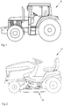
- FIG. 1 shows an agricultural vehicle 10 in which the magnetic transmission stage 16 according to the invention is used.
- Agricultural vehicles have in addition to the vehicle drive via a PTO, with the attached vehicles or machines can be driven.
- the gear stage 16 according to the invention can be used here as a variable torque limiter for setting a specific, delivered to the ancillaries, power that is transmitted via the PTO.
- the transmission stage 16 according to the invention can be used for the measurement of a transmitted power.
- the gear stage 16 can be provided in a drive train, such as between a drive unit and the chassis or an existing cutting or floor tool.
- FIG. 2 shows a work vehicle 12 for green areas, for example, a ride-on mower.
- the transmission stage 16 can in this case be provided in the drive train. This can be used to transfer power from the drive unit to the chassis. It can also be provided for driving the mowing tools or other floor tools.
- the slipping behavior of the gear stage 16 is advantageous if, for example, the mowing tool is blocked. The slipping behavior of the gear stage 16 allows the mower to be decoupled from the drive and prevents further power from being transmitted for a short time. The mowing tool can decelerate or dodge, so that damage to the tool is prevented.
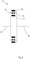
- the gear stage 16 consists in particular of an inner ring 18, a middle ring 20 and an outer ring 22.
- the middle ring 20 in this case has ferromagnetic rods 24, which are represented by black rectangles.
- the outer ring 22 and the inner ring 18 each have magnetic poles 26, 28 which differ in number from each other and cooperate together with the ferromagnetic rods 24 of the middle ring 20.
- the gear stage 16 has a first torque interface 30, approximately in the form of a shaft, which may also be a hollow shaft. The introduced torque is first passed to the inner ring 18 in the present embodiment. This is about the arrangement of the magnetic poles 26, 28 with both the middle ring 20, and the outer ring 22 in operative connection.
- the introduced torque is modulated by the middle ring 20 and directed to the outer ring 22.
- the changed torque is passed through the outer ring 22 to a second torque interface 32.
- the torque introduction can also be carried out in the reverse order, or the introduction or discharge via the middle ring 20 done.
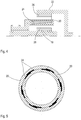
- FIG. 4 shows a longitudinal section through a structure according to the invention of the magnetic gear stage 16.
- the inner ring 18 has in a plane perpendicular to the longitudinal axis of magnetic poles 28, which are distributed on a circumference of the inner ring 18.
- the inner ring 18 may be formed in the form of a shaft or a hollow shaft.
- the number of magnetic poles 28 on the inner ring 18 can be arbitrary. However, this defines, together with the number of ferromagnetic rods 24 and the number of magnetic poles 26 on the outer ring 22, the behavior of the transmission stage 16 according to the invention.
- An outer ring 22, with a different number of magnetic poles 26, is provided in the same plane. On the outer ring 22, the magnetic poles 26 are also distributed on a circumference.
- a middle ring 20 which has ferromagnetic rods 24.
- a ferromagnetic rod 24 is in Fig. 4 shown in longitudinal section.
- the rod 24 has a wedge-shaped cross section and extends in the axial direction of the magnetic epicyclic gear 16 with a greater length beyond the plane of the magnetic poles 26, 28 also.
- the middle ring 20 supports the ferromagnetic rods 24 and is supported to permit axial displacement of the middle ring 20 relative to the inner ring 18 and the outer ring 22. Furthermore, the middle ring 20 can rotate independently of the other rings about the longitudinal axis or be set relative to the other rings in a standstill.
- the axial displacement of the middle ring 20 can be realized by a tongue and groove profile or a thread with which the middle ring 20 is held in a housing. Due to the spline profile of the ferromagnetic rods 24 and the longitudinal displaceability of the central ring 20, the portions of the ferromagnetic rods 24 that are in operative engagement with the outer ring 22 and the inner ring 18 can be varied so that an increasing or decreasing active cross section the ferromagnetic rods 24 can be adjusted. As a result, the parameters of the magnetic planetary gear 16 can be changed and adapted to the operating conditions.
- the magnetic ratio between the inner ring 18 and the outer ring 22 can be changed, so that a transmission ratio between an input and output of the gear stage 16 is adjustable. It is also possible thereby completely stop the gear stage 16, so that no power is transmitted.
- a standstill of the output shaft only leads to a standstill of the outer ring 22 and the magnetic poles 26. A mechanical connection between the individual rings does not exist, so that a distortion is avoided, as well as possible damage and Wear.
- FIG. 5 shows a cross section of the middle ring 20 in a further embodiment.
- the middle ring 20 has a two-part shape.
- the middle ring 20 is formed by an outer and inner cylindrical area, wherein both areas can rotate or move against each other. Both areas have ferromagnetic bars 24. By twisting or shifting the two areas, overlapping occurs between the ferromagnetic bars 24 in the respective areas, so that, depending on the overlap, the magnetic characteristic of the central ring 20 is changed overall.
- the two regions may have a different number of ferromagnetic rods 24.
- the ferromagnetic rods 24 may also be provided at different circumferential angles of the two regions, so that a Gradation of the overlap of the ferromagnetic rods 24 can be adjusted circumferentially by twisting or moving.
- the positions of the two regions of the middle ring 20 can be controlled by an actuator, so that an adapted power transmission of the gear stage 16 is adjustable.
Landscapes
- Engineering & Computer Science (AREA)
- Power Engineering (AREA)
- Retarders (AREA)
- Dynamo-Electric Clutches, Dynamo-Electric Brakes (AREA)
Abstract
Description
- Die Erfindung betrifft magnetisches Umlaufgetriebe mit einem variierbaren Drehmoment und weiterhin ein Verfahren zur Steuerung.
- Magnetische Umlaufgetriebe werden zur Drehmomentübertragung genutzt. Diese sind hinreichend bekannt. Ein solches magnetisches Umlaufgetriebe ist in
DE 10 2016 210 333.4 gezeigt. Sie bieten gegenüber mechanischen Umlaufgetriebestufen Vorteile, wie eine sichere Begrenzung des zu übertragenden Drehmoments. Im Falle eines zu hohen Drehmomentes kann das magnetische Umlaufgetriebe überdrehen oder durchrutschen und begrenzt dadurch das übertragene Drehmoment auf voreingestellte Parameter.DE 10 2016 210 333.4 dient zugleich als Grundlage und ist vollständig in die vorliegende Erfindung mit einbezogen. - Das Verhalten zur Drehmomentbegrenzung einer magnetischen Getriebestufe ist durch die Konstruktion festgelegt und sämtliche Geometrien, die hierbei definiert werden, tragen zu dem Verhalten des magnetischen Umlaufgetriebes und der übertragbaren Höhe des Drehmoments bei. Während dem Betrieb sind diese Kenngrößen somit nicht mehr anpassbar bzw. es muss eine vollständige Neukonstruktion erfolgen.
- Die Möglichkeit, die Drehmomentübertragung im Betrieb weiterhin verändern zu können, würde den Einsatz des magnetischen Umlaufgetriebes als Drehmomentwandler und zusätzlich als variablen Drehmomentbegrenzer erlauben. Weiterhin könnte auch der Einsatz als Kupplung ermöglicht werden. In weiterer Folge wäre dadurch eine Reduzierung der Komplexität möglich, durch die Reduktion von Bauteilen, Kostensenkung und Bauraumverkleineru ng.
- Es ist die Aufgabe der vorliegenden Erfindung, ein magnetisches Umlaufgetriebe zur Verfügung zu stellen, bei welchem die Parameter während dem Betrieb einstellbar sind.
- Die Aufgabe wird erfindungsgemäß durch die Lehre des Patentanspruchs 1 gelöst. Weitere vorteilhafte Ausgestaltungen und Weiterbildungen der Erfindung gehen aus den Unteransprüchen hervor.
- Das erfindungsgemäße magnetisches Umlaufgetriebe umfasst einen inneren Ring mit einer ersten Anzahl von Magnetpolen, einen mittleren Ring mit einer Anzahl ferromagnetischer Stäbe, einen äußeren Ring mit einer zweiten Anzahl von Magnetpolen, die sich von der ersten Anzahl unterscheidet, und eine Steuerung, wobei der mittlere Ring derart konfiguriert ist, dass das übertragbare Drehmoment während dem Betrieb durch die Steuerung variierbar ist.
- Das Umlaufgetriebe erlaubt ein einstellbares, zu übertragendes Drehmoment. Mit Hilfe der Steuerung kann eine Überwachung des Drehmoments durchgeführt werden. Durch eine Auswertung der Kennzahlen ist eine Load-Sensing Funktion ermöglicht, die gezielt ein bestimmtes Drehmomentniveau festlegt, überwacht und gegebenenfalls anpasst. Das Umlaufgetriebe kann als variabler Drehmomentbegrenzer eingesetzt werden. Die Drehmomentüberwachung kann an sich verändernde Umgebungsbedingungen oder Betriebszustände angepasst werden. Mittels der Drehbegrenzungsfunktion kann das Umlaufgetriebe auch als Trennkupplung eingesetzt werden, die eine Leistungsunterbrechung ab einem bestimmten Niveau automatisch umsetzt und angeschlossenen Baukomponenten oder Anhängebauteile vor einer Überlastung und damit vor einer Beschädigung schützt.
- In einer weitere Ausführung ist der mittlere Ring derart konfiguriert, dass die Geometrie des Umlaufgetriebes veränderbar ist.
- Die Geometrie kann dabei diskret oder kontinuierlich verändert werden. Der Luftspalt zwischen den einzelnen Ringen kann in kleinen Schritten angepasst werden oder konstruktiv durch feste Positionsveränderungen realisiert werden. Dies kann auch für die Breite erfolgen. Es ist möglich, die Spaltposition zu verschieben, etwa durch seitliches Verschieben von benachbarten Ringen. Es können abschnittsweise auf den Ringen unterschiedliche Materialen für die ferromagnetischen Stäbe oder die Magnetpole zum Einsatz kommen. Durch ein diskretes Verschieben oder Verdrehen können die Materialeigenschaften und damit die Kennzahlen des Umlaufgetriebes verändert werden. Das Umlaufgetriebe erlaubt eine Anpassung der Drehmomentdurchlässigkeit und ist flexibel einsetzbar.
- Bei einer Ausbildung ist der mittlere Ring derart konfiguriert, dass der Spalt zwischen dem äußeren und dem mittleren Ring veränderbar ist.
- Durch ein Verändern des Spalts können die Kennwerte des Umlaufgetriebes verstellt werden. Der magnetische Fluss wird verändert, wobei das Durchrutschverhalten des Umlaufgetriebes beeinflusst wird. Die Veränderung kann entweder durch ein axiales Verschieben oder durch ein Verdrehen eines kreisförmigen Ringbereichs erfolgen.
- In einer Weiterbildung ist der mittlere Ring derart konfiguriert, dass der Spalt zwischen dem inneren und dem mittleren Ring veränderbar ist. Die Veränderung kann entweder durch ein axiales Verschieben oder durch ein Verdrehen eines kreisförmigen Ringbereichs erfolgen. Durch ein Verändern des Spalts können die Kennwerte des Umlaufgetriebes verstellt werden. Der magnetische Fluss wird verändert, wobei das Durchrutschverhalten des Umlaufgetriebes beeinflusst wird.
- Bei einer Ausführung ist der mittlere Ring axial verschiebbar.
- Mit der axialen Verschiebung kann die Geometrie des Ringspalts und damit die magnetische Kennlinie verändert werden und eine Anpassung des Rutschmoments vorgenommen werden.
- In einer weiteren Ausbildung weist der mittlere Ring wenigstens zwei Gruppen von, aus unterschiedlichem Material gebildeten, ferromagnetischen Stäben auf, die derart am mittleren Ring vorgesehen sind, dass jeweils eine Gruppe durch axiales Verschieben Drehmoment überträgt.
- Je eine Gruppe kommt etwa durch Verdrehen oder Verschieben des Rings in den wirksamen Eingriff. Aufgrund der unterschiedlichen Materialgruppen kann vorteilhaft die Kennlinie des Umlaufgetriebes verändert werden. Es ist auch möglich, hierdurch eine Kupplungsfunktion umzusetzen. Beide Materialgruppen haben unterschiedlichen magnetische Kennwerte, so dass durch ein Umschalten zwischen diesen ein geändertes Verhalten des Umlaufgetriebes einstellbar ist. Hierdurch wird vermieden, dass das Umlaufgetriebe lediglich eine Betriebsart aufweist und es können mehrere Betriebsarten realisiert werden.
- Bei einer Weiterbildung ist der mittlere Ring derart konfiguriert, dass die Breite des Spalts zwischen dem äußeren und dem mittleren Ring veränderbar ist.
- Die Veränderung kann entweder durch ein axiales Verschieben oder durch ein Verdrehen eines kreisförmigen Ringbereichs erfolgen.
- Der mittlere Ring kann so vorgesehen sein, dass etwa durch axiales Verschieben eine Änderungen des Spalts verursacht wird. Es ist denkbar, die Spaltveränderung durch Verdrehen des Rings relativ zu einer Nulllage durchzuführen. Mit der Spaltänderung wird die magnetische Kennlinie verändert, so dass eine Anpassung des Umlaufgetriebes durchführbar ist.
- In einer Ausführung ist der mittlere Ring derart konfiguriert, dass die Breite des Spalts zwischen dem inneren und dem mittleren Ring veränderbar ist.
- Die Veränderung kann entweder durch ein axiales Verschieben oder durch ein Verdrehen eines kreisförmigen Ringbereichs erfolgen.
- Der mittlere Ring kann so vorgesehen sein, dass etwa durch axiales Verschieben eine Änderungen des Spalts verursacht wird. Es ist denkbar, die Spaltveränderung durch Verdrehen des Rings relativ zu einer Nulllage durchzuführen. Mit der Spaltänderung wird die magnetische Kennlinie verändert, so dass eine Anpassung des Umlaufgetriebes durchführbar ist.
- Bei einer Ausgestaltung weist der äußere Ring elektrische Spulen auf, um die Magnetpole zu bilden.
- Die elektrischen Spulen können durch eine Steuerung aktiv ansteuerbar sein. Dies ermöglicht das abgestimmte An- und Abschalten einzelner Spulenbaugruppen. Dies verändert wiederrum die Kennzahlen des Umlaufgetriebes, wodurch ein Schlupfmoment einstellbar ist. Mit Hilfe von aktiven Spulen können zahlreiche unterschiedliche Konfigurationen realisiert werden, die eine Abstufung des Schlupfmomentes während dem Betrieb ermöglicht.
- In einer Ausbildung weist der innere Ring elektrische Spulen auf, um die Magnetpole zu bilden.
- Die elektrischen Spulen können durch eine Steuerung aktiv ansteuerbar sein. Dies ermöglicht das abgestimmte An- und Abschalten einzelner Spulenbaugruppen. Dies verändert wiederrum die Kennzahlen des Umlaufgetriebes, wodurch ein Schlupfmoment einstellbar ist. Mit Hilfe von aktiven Spulen können zahlreiche unterschiedliche Konfigurationen realisiert werden, die eine Abstufung des Schlupfmomentes während dem Betrieb ermöglicht.
- Weitere Ausbildungen der Erfindung werden in den folgenden Figuren beschreiben. Dabei zeigen:
- Figur 1
- eine Ausführung der Erfindung in einem landwirtschaftlichen Fahrzeug;
- Figur 2
- eine Ausbildung der Erfindung in einem Fahrzeug zur Bearbeitung von Grünflächen;
- Figur 3
- einen beispielhaften Aufbau der Erfindung;
- Figur 4
- einen Querschnitt einer Ausführung der Erfindung;
- Figur 5
- einen weiteren Querschnitt einer Ausführung der Erfindung.
-
Figur 1 zeigt ein landwirtschaftliches Fahrzeug 10, in dem die erfindungsgemäße magnetische Getriebestufe 16 verwendet wird. Landwirtschaftliche Fahrzeuge verfügen zusätzlich zum Fahrzeugantrieb über einen Zapfwellenantrieb, mit dem angehängte Fahrzeuge oder Maschinen angetrieben werden können. Die erfindungsgemäße Getriebestufe 16 kann hierbei als variabler Drehmomentbegrenzer zur Einstellung einer bestimmten, an die Nebenaggregate abgegebenen, Leistung verwendet werden, die über die Zapfwelle übertragen wird. Ebenso kann die erfindungsgemäße Getriebestufe 16 für die Messung einer übertragenen Leistung verwendet werden. Die Getriebestufe 16 kann in einem Antriebsstrang, etwa zwischen einem Antriebsaggregat und dem Fahrwerk oder einem vorhandenen Schneidwerk oder Bodenwerkzeug vorgesehen sein. Weiterhin ist denkbar, die erfindungsgemäße Getriebestufe 16 im Nebenaggregat bzw. Anhängefahrzeug selbst vorzusehen und zu verwenden. -
Figur 2 zeigt einen Arbeitsfahrzeug 12 für Grünflächen, zum Beispiel einen Aufsitzmäher. Die erfindungsgemäße Getriebestufe 16 kann hierbei im Antriebsstrang vorgesehen sein. Dabei kann diese zur Übertragung von Leistung vom Antriebsaggregat an das Fahrwerk verwendet werden. Sie kann auch für den Antrieb der Mähwerkzeuge oder weiterer Bodenwerkzeuge vorgesehen sein. Vorteilhaft ist das Durchrutschverhalten der Getriebestufe 16, wenn beispielsweise das Mähwerkzeug blockiert wird. Das Durchrutschverhalten der Getriebestufe 16 ermöglicht ein Entkoppeln des Mähwerkzeugs vom Antrieb und verhindert, dass kurzzeitig weiter Leistung übertragen wird. Das Mähwerkzeug kann abbremsen oder ausweichen, so dass eine Beschädigung des Werkzeugs verhindert wird. -
Figur 3 zeigt eine funktionale Ausführung der erfindungsgemäßen magnetischen Getriebestufe 16. Die Getriebestufe 16 besteht insbesondere aus einem inneren Ring 18, einem mittleren Ring 20 und einem äußeren Ring 22. Der mittlere Ring 20 weist dabei ferromagnetische Stäbe 24 auf, die durch schwarze Rechtecke dargestellt sind. Der äußere Ring 22 und der innere Ring 18 weisen jeweils Magnetpole 26, 28 auf, die sich in ihrer Anzahl jeweils voneinander unterscheiden und zusammen mit den ferromagnetischen Stäben 24 des mittleren Rings 20 zusammenwirken. Die Getriebestufe 16 weist eine erste Drehmomentenschnitttstelle 30 auf, etwa in Form einer Welle, die auch eine Hohlwelle sein kann. Das eingeleitete Drehmoment wird in der vorliegenden Ausführung zunächst an den inneren Ring 18 geleitet. Dieser steht über die Anordnung der Magnetpole 26, 28 sowohl mit dem mittleren Ring 20, als auch dem äußeren Ring 22 in Wirkverbindung. Das eingeleitete Drehmoment wird durch den mittleren Ring 20 moduliert und an den äußeren Ring 22 geleitet. Das veränderte Drehmoment wird durch den äußeren Ring 22 an eine zweite Drehmomentenschnittstelle 32 weitergeleitet. Denkbar sind auch andere Aufbauten, die je nach Anwendung zweckmäßig erscheinen. So kann die Drehmomenteinleitung auch in umgekehrter Reihenfolge durchgeführt werden, oder die Einleitung oder Ausleitung über den mittleren Ring 20 erfolgen. -
Figur 4 zeigt einen Längsschnitt durch einen erfindungsgemäßen Aufbau der magnetischen Getriebestufe 16. Der innere Ring 18 weist dabei in einer Ebene senkrecht zur Längsachse Magnetpole 28 auf, die an einem Umfang des inneren Rings 18 verteilt sind. Der innere Ring 18 kann in Form einer Welle oder auch einer Hohlwelle ausgebildet sein. Die Anzahl der Magnetpole 28 am inneren Ring 18 kann beliebig sein. Diese legt jedoch zusammen mit der Anzahl der ferromagnetischen Stäbe 24 und der Anzahl der Magnetpole 26 am äußeren Ring 22 das Verhalten der erfindungsgemäßen Getriebestufe 16 fest. Ein äußerer Ring 22, mit einer unterschiedlichen Anzahl von Magnetpolen 26, ist in der gleichen Ebene vorgesehen. Am äußeren Ring 22 sind die Magnetpole 26 ebenfalls am einem Umfang verteilt angeordnet. - Zwischen dem inneren Ring 18 und dem äußeren Ring 22 ist ein mittlerer Ring 20 vorgesehen, der ferromagnetische Stäbe 24 aufweist. Ein ferromagnetischer Stab 24 ist in
Fig. 4 im Längsschnitt gezeigt. Dabei weist der Stab 24 einen keilförmigen Querschnitt auf und erstreckt sich in axialer Richtung des magnetischen Umlaufgetriebes 16 mit einer größeren Länge über die Ebene der Magnetpole 26, 28 hinaus. Der mittlere Ring 20 stützt die ferromagnetischen Stäbe 24 und ist derart gelagert, dass er eine axiale Verschiebung des mittleren Rings 20 relativ zum inneren Ring 18 und zum äußeren Ring 22 gestattet. Weiterhin kann sich der mittlere Ring 20 unabhängig von den weiteren Ringen um die Längsachse drehen oder relativ zu den weiteren Ringen in Stillstand gesetzt werden. Das axiale Verschieben des mittleren Rings 20 kann durch ein Nut-Feder Profil oder ein Gewinde realisiert sein, mit dem der mittlere Ring 20 in einem Gehäuse gehalten ist. Aufgrund des Keilprofils der ferromagnetischen Stäbe 24 und der Längsverschieblichkeit des mittleren Rings 20 können die Abschnitte der ferromagnetischen Stäbe 24, die sich im Wirkeingriff mit dem äußeren Ring 22 und dem inneren Ring 18 befinden, variiert werden, so dass ein zu- oder abnehmender aktiver Querschnitt der ferromagnetischen Stäbe 24 eingestellt werden kann. Hierdurch lassen sich die Parameter des magnetischen Umlaufgetriebes 16 verändern und an die Betriebsbedingungen anpassen. Durch die Veränderung des Querschnitts der ferromagnetischen Stäbe 24 kann etwa die magnetische Übersetzung zwischen dem inneren Ring 18 und dem äußeren Ring 22 verändert werden, so dass ein Übersetzungsverhältnis zwischen einem Eingang und Ausgang der Getriebestufe 16 einstellbar ist. Es ist weiterhin möglich, dadurch die Getriebestufe 16 auch vollständig stillzusetzten, so dass keine Leistung übertragen wird. Im Falle einer Blockade auf der Ausgangsseite der Getriebestufe 16 führt ein Stillstand der Ausgangswelle lediglich zu einem Stillstand des äußeren Rings 22 und der Magnetpole 26. Eine mechanische Verbindung zwischen den einzelnen Ringen besteht nicht, so dass ein Verspannen vermieden wird, ebenso wie mögliche Beschädigungen und Verschleiß. -
Figur 5 zeigt einen Querschnitt des mittleren Rings 20 bei einer weiteren Ausführung. Der mittlere Ring 20 weist eine zweigeteilte Form auf. Dabei ist der mittlere Ring 20 durch einen äußeren und inneren zylinderförmigen Bereich gebildet, wobei sich beide Bereiche gegeneinander verdrehen oder verschieben lassen. Beide Bereiche weisen ferromagnetische Stäbe 24 auf. Durch das Verdrehen oder Verschieben der beiden Bereiche kommt es zwischen den ferromagnetischen Stäben 24 in den jeweiligen Bereichen zur Überlappung, so dass je nach Überlappung die magnetische Kennlinie des mittleren Rings 20 insgesamt verändert wird. Die beiden Bereiche können eine unterschiedliche Anzahl von ferromagnetischen Stäben 24 aufweisen. Die ferromagnetischen Stäbe 24 können auch an unterschiedlichen Umfangswinkeln der beiden Bereiche vorgesehen sein, so dass eine Abstufung des Überlappung der ferromagnetischen Stäbe 24 am Umfang durch Verdrehen oder Verschieben eingestellt werden kann. - Die Positionen der beiden Bereiche des mittleren Rings 20 können hierbei durch einen Stellantrieb angesteuert werden, so dass eine angepasste Leistungsübertragung der Getriebestufe 16 einstellbar ist.
Claims (10)
- Magnetisches Umlaufgetriebe (16), umfassend
einen inneren Ring (18) mit einer ersten Anzahl von Magnetpolen (26, 28),
einen mittleren Ring (20) mit einer Anzahl ferromagnetischer Stäbe (24),
einen äußeren Ring (22) mit einer zweiten Anzahl von Magnetpolen (26, 28), die sich von der ersten Anzahl unterscheidet,
wobei der mittlere Ring (20) derart konfiguriert ist, dass das übertragbare Drehmoment während dem Betrieb variierbar ist. - Magnetisches Umlaufgetriebe (16) nach Anspruch 1, wobei der mittlere Ring (20) derart konfiguriert ist, dass die Geometrie des Umlaufgetriebes (16) veränderbar ist.
- Magnetisches Umlaufgetriebe (16) nach Anspruch 2, wobei der mittlere Ring (20) derart konfiguriert ist, dass ein Spalt zwischen dem äußeren (22) und dem mittleren Ring (20) veränderbar ist.
- Magnetisches Umlaufgetriebe (16) nach einem der vorangehenden Ansprüche, wobei der mittlere Ring (20) derart konfiguriert ist, dass ein Spalt zwischen dem inneren (18) und dem mittleren Ring (20) veränderbar ist.
- Magnetisches Umlaufgetriebe (16) nach einem der vorangehenden Ansprüche, wobei der mittlere Ring (20) axial verschiebbar ist.
- Magnetisches Umlaufgetriebe (16) nach Anspruch 5, wobei der mittlere Ring (20) wenigstens zwei Gruppen von, aus unterschiedlichem Material gebildeten, ferromagnetischen Stäben (24) aufweist, die derart am mittleren Ring (20) vorgesehen sind, dass jeweils eine Gruppe durch axiales Verschieben Drehmoment überträgt.
- Magnetisches Umlaufgetriebe (16) nach einem der vorangehenden Ansprüche, wobei der mittlere Ring (20) derart konfiguriert ist, dass die Breite eines Spalts zwischen dem äußeren (22) und dem mittleren Ring (20) veränderbar ist.
- Magnetisches Umlaufgetriebe (16) nach einem der vorangehenden Ansprüche, wobei der mittlere Ring (20) derart konfiguriert ist, dass die Breite eines Spalts zwischen dem inneren (18) und dem mittleren Ring (20) veränderbar ist.
- Magnetisches Umlaufgetriebe (16) nach einem der vorangehenden Ansprüche, wobei der äußere Ring (22) elektrische Spulen aufweist, um die Magnetpole (26, 28) zu bilden.
- Magnetisches Umlaufgetriebe (16) nach einem der vorangehenden Ansprüche, wobei der innere Ring (18) elektrische Spulen aufweist, um die Magnetpole (26, 28) zu bilden.
Applications Claiming Priority (1)
| Application Number | Priority Date | Filing Date | Title |
|---|---|---|---|
| DE102017208985.7A DE102017208985A1 (de) | 2017-05-29 | 2017-05-29 | Magnetisches Umlaufgetriebe mit variierbarem Drehmoment |
Publications (2)
| Publication Number | Publication Date |
|---|---|
| EP3410588A1 true EP3410588A1 (de) | 2018-12-05 |
| EP3410588B1 EP3410588B1 (de) | 2022-08-31 |
Family
ID=62116754
Family Applications (1)
| Application Number | Title | Priority Date | Filing Date |
|---|---|---|---|
| EP18170897.5A Active EP3410588B1 (de) | 2017-05-29 | 2018-05-04 | Magnetisches umlaufgetriebe mit variierbarem drehmoment |
Country Status (2)
| Country | Link |
|---|---|
| EP (1) | EP3410588B1 (de) |
| DE (1) | DE102017208985A1 (de) |
Cited By (3)
| Publication number | Priority date | Publication date | Assignee | Title |
|---|---|---|---|---|
| EP3543058A1 (de) * | 2018-03-22 | 2019-09-25 | Deere & Company | Zapfwellengetriebe |
| US11670995B2 (en) | 2020-01-31 | 2023-06-06 | Deere & Company | Method and apparatus for operating a dual rotor electrical machine |
| US11691497B2 (en) | 2020-07-29 | 2023-07-04 | Deere & Company | Transmission system |
Citations (6)
| Publication number | Priority date | Publication date | Assignee | Title |
|---|---|---|---|---|
| US5675203A (en) * | 1994-03-15 | 1997-10-07 | Volkswagen Ag | Motor/generator arrangement having a movable common stator |
| US20110215668A1 (en) * | 2010-03-03 | 2011-09-08 | Industrial Technology Research Institute | Magnetic transmission assembly |
| EP2411699A1 (de) * | 2009-03-27 | 2012-02-01 | Ricardo Uk Limited | Schwungrad |
| US20130002075A1 (en) * | 2010-01-19 | 2013-01-03 | Rolls-Royce Plc | Magnetic gear arrangement |
| DE102012022456A1 (de) * | 2012-11-15 | 2014-05-15 | Volkswagen Aktiengesellschaft | Planetengetriebe, Drehmomentübertragungsvorrichtung und Verwendung derselben |
| CN106341031A (zh) * | 2016-09-13 | 2017-01-18 | 江苏大学 | 一种磁场调制式磁力丝杠 |
Family Cites Families (8)
| Publication number | Priority date | Publication date | Assignee | Title |
|---|---|---|---|---|
| DE4405701A1 (de) | 1994-02-23 | 1995-08-24 | Philips Patentverwaltung | Magnetisches Getriebe mit mehreren magnetisch zusammenwirkenden, relativ zueinander beweglichen Teilen |
| JP3444324B2 (ja) | 1995-11-30 | 2003-09-08 | いすゞ自動車株式会社 | 永久磁石式渦電流減速装置 |
| DE19746359C2 (de) | 1997-01-22 | 2003-02-06 | Eugen Schmidt | Regelbare Kühlmittelpumpe für Kraftfahrzeuge |
| DE10322473A1 (de) | 2003-05-19 | 2004-12-16 | Robert Bosch Gmbh | Elektrisches Antriebsaggregat |
| US7791235B2 (en) * | 2006-12-22 | 2010-09-07 | General Electric Company | Variable magnetic coupling of rotating machinery |
| GB2457226B (en) | 2008-01-11 | 2013-01-09 | Magnomatics Ltd | Drives for sealed systems |
| DE102009039658B4 (de) | 2009-09-02 | 2016-08-04 | Ringfeder Power-Transmission Gmbh | Permanentmagnetkupplung für die synchrone Übertragung von Drehbewegungen |
| DE102014210299A1 (de) | 2014-05-30 | 2015-12-03 | Mahle International Gmbh | Magnetkupplung |
-
2017
- 2017-05-29 DE DE102017208985.7A patent/DE102017208985A1/de not_active Withdrawn
-
2018
- 2018-05-04 EP EP18170897.5A patent/EP3410588B1/de active Active
Patent Citations (6)
| Publication number | Priority date | Publication date | Assignee | Title |
|---|---|---|---|---|
| US5675203A (en) * | 1994-03-15 | 1997-10-07 | Volkswagen Ag | Motor/generator arrangement having a movable common stator |
| EP2411699A1 (de) * | 2009-03-27 | 2012-02-01 | Ricardo Uk Limited | Schwungrad |
| US20130002075A1 (en) * | 2010-01-19 | 2013-01-03 | Rolls-Royce Plc | Magnetic gear arrangement |
| US20110215668A1 (en) * | 2010-03-03 | 2011-09-08 | Industrial Technology Research Institute | Magnetic transmission assembly |
| DE102012022456A1 (de) * | 2012-11-15 | 2014-05-15 | Volkswagen Aktiengesellschaft | Planetengetriebe, Drehmomentübertragungsvorrichtung und Verwendung derselben |
| CN106341031A (zh) * | 2016-09-13 | 2017-01-18 | 江苏大学 | 一种磁场调制式磁力丝杠 |
Cited By (4)
| Publication number | Priority date | Publication date | Assignee | Title |
|---|---|---|---|---|
| EP3543058A1 (de) * | 2018-03-22 | 2019-09-25 | Deere & Company | Zapfwellengetriebe |
| US10959366B2 (en) | 2018-03-22 | 2021-03-30 | Deere & Company | Power take-off transmission |
| US11670995B2 (en) | 2020-01-31 | 2023-06-06 | Deere & Company | Method and apparatus for operating a dual rotor electrical machine |
| US11691497B2 (en) | 2020-07-29 | 2023-07-04 | Deere & Company | Transmission system |
Also Published As
| Publication number | Publication date |
|---|---|
| DE102017208985A1 (de) | 2018-11-29 |
| EP3410588B1 (de) | 2022-08-31 |
Similar Documents
| Publication | Publication Date | Title |
|---|---|---|
| EP2853431B1 (de) | Zapfwellengetriebe für eine landwirtschaftliche Arbeitsmaschine | |
| DE2338275C2 (de) | Synchronisierungsvorrichtung | |
| WO2020120723A1 (de) | Antriebsachse eines elektrofahrzeuges | |
| DE102013007354A1 (de) | Verfahren zum Betreiben einer Antriebseinrichtung eines Kraftfahrzeugs sowie entsprechende Antriebseinrichtung | |
| DE112017004344T5 (de) | Kombination aus achsabschaltung und differentialsperrung | |
| EP3410588B1 (de) | Magnetisches umlaufgetriebe mit variierbarem drehmoment | |
| WO2023011978A1 (de) | Elektrische antriebsvorrichtung für eine fahrzeugachse | |
| EP3543058A1 (de) | Zapfwellengetriebe | |
| EP2857246B1 (de) | Landwirtschaftliche Arbeitsmaschine | |
| EP4290099B1 (de) | Nutzfahrzeug | |
| EP0262626A1 (de) | Antriebsvorrichtung von Rädern zweier Achsen | |
| EP3882478B1 (de) | Antriebsstrang mit einer beweglichen kupplung zwischen einer motorwelle und einer eingangswelle eines schaltgetriebes | |
| EP4098908B1 (de) | Zapfwellengetriebe und landwirtschaftliches nutzfahrzeug | |
| DE102008039928A1 (de) | Differentialgetriebeeinheit | |
| DE10033811B4 (de) | Schalteinrichtung | |
| DE112019007903T5 (de) | Untersetzungsgetriebebaugruppe | |
| EP0890045B1 (de) | Verfahren zum steuern eines wendegetriebes zur reduzierung der thermischen belastung von schaltelementen | |
| EP3034348A1 (de) | Verteilergetriebe zum Aufteilen eines Drehmoments auf wenigstens eine erste und eine zweite Achswelle eines Kraftfahrzeugs | |
| EP3405692A1 (de) | Getriebewelle, bauteilpaarung und verfahren zum betrieb einer getriebewelle | |
| EP0665130A1 (de) | Zapfwellenanordnung | |
| DE102022201484B4 (de) | Getriebevorrichtung für ein Kraftfahrzeug | |
| EP3757423B1 (de) | Schaltgetriebe | |
| EP1596103B1 (de) | Stelleinheit zur automatisierten Betätigung eines Schaltgetriebes | |
| EP3658800A1 (de) | Schaltwalze und kraftfahrzeug-schaltgetriebe | |
| DE102022201713A1 (de) | Getriebevorrichtung für ein Kraftfahrzeug |
Legal Events
| Date | Code | Title | Description |
|---|---|---|---|
| PUAI | Public reference made under article 153(3) epc to a published international application that has entered the european phase |
Free format text: ORIGINAL CODE: 0009012 |
|
| STAA | Information on the status of an ep patent application or granted ep patent |
Free format text: STATUS: THE APPLICATION HAS BEEN PUBLISHED |
|
| AK | Designated contracting states |
Kind code of ref document: A1 Designated state(s): AL AT BE BG CH CY CZ DE DK EE ES FI FR GB GR HR HU IE IS IT LI LT LU LV MC MK MT NL NO PL PT RO RS SE SI SK SM TR |
|
| AX | Request for extension of the european patent |
Extension state: BA ME |
|
| STAA | Information on the status of an ep patent application or granted ep patent |
Free format text: STATUS: REQUEST FOR EXAMINATION WAS MADE |
|
| 17P | Request for examination filed |
Effective date: 20190605 |
|
| RBV | Designated contracting states (corrected) |
Designated state(s): AL AT BE BG CH CY CZ DE DK EE ES FI FR GB GR HR HU IE IS IT LI LT LU LV MC MK MT NL NO PL PT RO RS SE SI SK SM TR |
|
| STAA | Information on the status of an ep patent application or granted ep patent |
Free format text: STATUS: EXAMINATION IS IN PROGRESS |
|
| 17Q | First examination report despatched |
Effective date: 20200424 |
|
| GRAP | Despatch of communication of intention to grant a patent |
Free format text: ORIGINAL CODE: EPIDOSNIGR1 |
|
| STAA | Information on the status of an ep patent application or granted ep patent |
Free format text: STATUS: GRANT OF PATENT IS INTENDED |
|
| INTG | Intention to grant announced |
Effective date: 20220422 |
|
| GRAS | Grant fee paid |
Free format text: ORIGINAL CODE: EPIDOSNIGR3 |
|
| GRAA | (expected) grant |
Free format text: ORIGINAL CODE: 0009210 |
|
| STAA | Information on the status of an ep patent application or granted ep patent |
Free format text: STATUS: THE PATENT HAS BEEN GRANTED |
|
| AK | Designated contracting states |
Kind code of ref document: B1 Designated state(s): AL AT BE BG CH CY CZ DE DK EE ES FI FR GB GR HR HU IE IS IT LI LT LU LV MC MK MT NL NO PL PT RO RS SE SI SK SM TR |
|
| REG | Reference to a national code |
Ref country code: CH Ref legal event code: EP Ref country code: GB Ref legal event code: FG4D Free format text: NOT ENGLISH |
|
| REG | Reference to a national code |
Ref country code: AT Ref legal event code: REF Ref document number: 1516037 Country of ref document: AT Kind code of ref document: T Effective date: 20220915 Ref country code: DE Ref legal event code: R096 Ref document number: 502018010507 Country of ref document: DE |
|
| REG | Reference to a national code |
Ref country code: FI Ref legal event code: FGE |
|
| REG | Reference to a national code |
Ref country code: IE Ref legal event code: FG4D Free format text: LANGUAGE OF EP DOCUMENT: GERMAN |
|
| REG | Reference to a national code |
Ref country code: LT Ref legal event code: MG9D |
|
| REG | Reference to a national code |
Ref country code: NL Ref legal event code: MP Effective date: 20220831 |
|
| PG25 | Lapsed in a contracting state [announced via postgrant information from national office to epo] |
Ref country code: SE Free format text: LAPSE BECAUSE OF FAILURE TO SUBMIT A TRANSLATION OF THE DESCRIPTION OR TO PAY THE FEE WITHIN THE PRESCRIBED TIME-LIMIT Effective date: 20220831 Ref country code: RS Free format text: LAPSE BECAUSE OF FAILURE TO SUBMIT A TRANSLATION OF THE DESCRIPTION OR TO PAY THE FEE WITHIN THE PRESCRIBED TIME-LIMIT Effective date: 20220831 Ref country code: NO Free format text: LAPSE BECAUSE OF FAILURE TO SUBMIT A TRANSLATION OF THE DESCRIPTION OR TO PAY THE FEE WITHIN THE PRESCRIBED TIME-LIMIT Effective date: 20221130 Ref country code: LV Free format text: LAPSE BECAUSE OF FAILURE TO SUBMIT A TRANSLATION OF THE DESCRIPTION OR TO PAY THE FEE WITHIN THE PRESCRIBED TIME-LIMIT Effective date: 20220831 Ref country code: LT Free format text: LAPSE BECAUSE OF FAILURE TO SUBMIT A TRANSLATION OF THE DESCRIPTION OR TO PAY THE FEE WITHIN THE PRESCRIBED TIME-LIMIT Effective date: 20220831 |
|
| PG25 | Lapsed in a contracting state [announced via postgrant information from national office to epo] |
Ref country code: PL Free format text: LAPSE BECAUSE OF FAILURE TO SUBMIT A TRANSLATION OF THE DESCRIPTION OR TO PAY THE FEE WITHIN THE PRESCRIBED TIME-LIMIT Effective date: 20220831 Ref country code: IS Free format text: LAPSE BECAUSE OF FAILURE TO SUBMIT A TRANSLATION OF THE DESCRIPTION OR TO PAY THE FEE WITHIN THE PRESCRIBED TIME-LIMIT Effective date: 20221231 Ref country code: HR Free format text: LAPSE BECAUSE OF FAILURE TO SUBMIT A TRANSLATION OF THE DESCRIPTION OR TO PAY THE FEE WITHIN THE PRESCRIBED TIME-LIMIT Effective date: 20220831 Ref country code: GR Free format text: LAPSE BECAUSE OF FAILURE TO SUBMIT A TRANSLATION OF THE DESCRIPTION OR TO PAY THE FEE WITHIN THE PRESCRIBED TIME-LIMIT Effective date: 20221201 |
|
| PG25 | Lapsed in a contracting state [announced via postgrant information from national office to epo] |
Ref country code: SM Free format text: LAPSE BECAUSE OF FAILURE TO SUBMIT A TRANSLATION OF THE DESCRIPTION OR TO PAY THE FEE WITHIN THE PRESCRIBED TIME-LIMIT Effective date: 20220831 Ref country code: RO Free format text: LAPSE BECAUSE OF FAILURE TO SUBMIT A TRANSLATION OF THE DESCRIPTION OR TO PAY THE FEE WITHIN THE PRESCRIBED TIME-LIMIT Effective date: 20220831 Ref country code: PT Free format text: LAPSE BECAUSE OF FAILURE TO SUBMIT A TRANSLATION OF THE DESCRIPTION OR TO PAY THE FEE WITHIN THE PRESCRIBED TIME-LIMIT Effective date: 20230102 Ref country code: ES Free format text: LAPSE BECAUSE OF FAILURE TO SUBMIT A TRANSLATION OF THE DESCRIPTION OR TO PAY THE FEE WITHIN THE PRESCRIBED TIME-LIMIT Effective date: 20220831 Ref country code: DK Free format text: LAPSE BECAUSE OF FAILURE TO SUBMIT A TRANSLATION OF THE DESCRIPTION OR TO PAY THE FEE WITHIN THE PRESCRIBED TIME-LIMIT Effective date: 20220831 Ref country code: CZ Free format text: LAPSE BECAUSE OF FAILURE TO SUBMIT A TRANSLATION OF THE DESCRIPTION OR TO PAY THE FEE WITHIN THE PRESCRIBED TIME-LIMIT Effective date: 20220831 |
|
| PG25 | Lapsed in a contracting state [announced via postgrant information from national office to epo] |
Ref country code: SK Free format text: LAPSE BECAUSE OF FAILURE TO SUBMIT A TRANSLATION OF THE DESCRIPTION OR TO PAY THE FEE WITHIN THE PRESCRIBED TIME-LIMIT Effective date: 20220831 Ref country code: EE Free format text: LAPSE BECAUSE OF FAILURE TO SUBMIT A TRANSLATION OF THE DESCRIPTION OR TO PAY THE FEE WITHIN THE PRESCRIBED TIME-LIMIT Effective date: 20220831 |
|
| REG | Reference to a national code |
Ref country code: DE Ref legal event code: R097 Ref document number: 502018010507 Country of ref document: DE |
|
| PG25 | Lapsed in a contracting state [announced via postgrant information from national office to epo] |
Ref country code: NL Free format text: LAPSE BECAUSE OF FAILURE TO SUBMIT A TRANSLATION OF THE DESCRIPTION OR TO PAY THE FEE WITHIN THE PRESCRIBED TIME-LIMIT Effective date: 20220831 Ref country code: AL Free format text: LAPSE BECAUSE OF FAILURE TO SUBMIT A TRANSLATION OF THE DESCRIPTION OR TO PAY THE FEE WITHIN THE PRESCRIBED TIME-LIMIT Effective date: 20220831 |
|
| PLBE | No opposition filed within time limit |
Free format text: ORIGINAL CODE: 0009261 |
|
| STAA | Information on the status of an ep patent application or granted ep patent |
Free format text: STATUS: NO OPPOSITION FILED WITHIN TIME LIMIT |
|
| 26N | No opposition filed |
Effective date: 20230601 |
|
| PG25 | Lapsed in a contracting state [announced via postgrant information from national office to epo] |
Ref country code: SI Free format text: LAPSE BECAUSE OF FAILURE TO SUBMIT A TRANSLATION OF THE DESCRIPTION OR TO PAY THE FEE WITHIN THE PRESCRIBED TIME-LIMIT Effective date: 20220831 |
|
| REG | Reference to a national code |
Ref country code: CH Ref legal event code: PL |
|
| PG25 | Lapsed in a contracting state [announced via postgrant information from national office to epo] |
Ref country code: MC Free format text: LAPSE BECAUSE OF FAILURE TO SUBMIT A TRANSLATION OF THE DESCRIPTION OR TO PAY THE FEE WITHIN THE PRESCRIBED TIME-LIMIT Effective date: 20220831 |
|
| REG | Reference to a national code |
Ref country code: BE Ref legal event code: MM Effective date: 20230531 |
|
| PG25 | Lapsed in a contracting state [announced via postgrant information from national office to epo] |
Ref country code: MC Free format text: LAPSE BECAUSE OF FAILURE TO SUBMIT A TRANSLATION OF THE DESCRIPTION OR TO PAY THE FEE WITHIN THE PRESCRIBED TIME-LIMIT Effective date: 20220831 Ref country code: LU Free format text: LAPSE BECAUSE OF NON-PAYMENT OF DUE FEES Effective date: 20230504 Ref country code: LI Free format text: LAPSE BECAUSE OF NON-PAYMENT OF DUE FEES Effective date: 20230531 Ref country code: CH Free format text: LAPSE BECAUSE OF NON-PAYMENT OF DUE FEES Effective date: 20230531 |
|
| REG | Reference to a national code |
Ref country code: IE Ref legal event code: MM4A |
|
| PG25 | Lapsed in a contracting state [announced via postgrant information from national office to epo] |
Ref country code: IE Free format text: LAPSE BECAUSE OF NON-PAYMENT OF DUE FEES Effective date: 20230504 |
|
| PG25 | Lapsed in a contracting state [announced via postgrant information from national office to epo] |
Ref country code: IE Free format text: LAPSE BECAUSE OF NON-PAYMENT OF DUE FEES Effective date: 20230504 |
|
| PG25 | Lapsed in a contracting state [announced via postgrant information from national office to epo] |
Ref country code: BE Free format text: LAPSE BECAUSE OF NON-PAYMENT OF DUE FEES Effective date: 20230531 |
|
| REG | Reference to a national code |
Ref country code: AT Ref legal event code: MM01 Ref document number: 1516037 Country of ref document: AT Kind code of ref document: T Effective date: 20230504 |
|
| PG25 | Lapsed in a contracting state [announced via postgrant information from national office to epo] |
Ref country code: AT Free format text: LAPSE BECAUSE OF NON-PAYMENT OF DUE FEES Effective date: 20230504 |
|
| PG25 | Lapsed in a contracting state [announced via postgrant information from national office to epo] |
Ref country code: AT Free format text: LAPSE BECAUSE OF NON-PAYMENT OF DUE FEES Effective date: 20230504 |
|
| PG25 | Lapsed in a contracting state [announced via postgrant information from national office to epo] |
Ref country code: BG Free format text: LAPSE BECAUSE OF FAILURE TO SUBMIT A TRANSLATION OF THE DESCRIPTION OR TO PAY THE FEE WITHIN THE PRESCRIBED TIME-LIMIT Effective date: 20220831 |
|
| PG25 | Lapsed in a contracting state [announced via postgrant information from national office to epo] |
Ref country code: BG Free format text: LAPSE BECAUSE OF FAILURE TO SUBMIT A TRANSLATION OF THE DESCRIPTION OR TO PAY THE FEE WITHIN THE PRESCRIBED TIME-LIMIT Effective date: 20220831 |
|
| PGFP | Annual fee paid to national office [announced via postgrant information from national office to epo] |
Ref country code: FI Payment date: 20250526 Year of fee payment: 8 |
|
| PGFP | Annual fee paid to national office [announced via postgrant information from national office to epo] |
Ref country code: DE Payment date: 20250423 Year of fee payment: 8 |
|
| PGFP | Annual fee paid to national office [announced via postgrant information from national office to epo] |
Ref country code: GB Payment date: 20250527 Year of fee payment: 8 |
|
| PGFP | Annual fee paid to national office [announced via postgrant information from national office to epo] |
Ref country code: IT Payment date: 20250521 Year of fee payment: 8 |
|
| PGFP | Annual fee paid to national office [announced via postgrant information from national office to epo] |
Ref country code: FR Payment date: 20250526 Year of fee payment: 8 |
|
| PG25 | Lapsed in a contracting state [announced via postgrant information from national office to epo] |
Ref country code: CY Free format text: LAPSE BECAUSE OF FAILURE TO SUBMIT A TRANSLATION OF THE DESCRIPTION OR TO PAY THE FEE WITHIN THE PRESCRIBED TIME-LIMIT; INVALID AB INITIO Effective date: 20180504 |
|
| PG25 | Lapsed in a contracting state [announced via postgrant information from national office to epo] |
Ref country code: HU Free format text: LAPSE BECAUSE OF FAILURE TO SUBMIT A TRANSLATION OF THE DESCRIPTION OR TO PAY THE FEE WITHIN THE PRESCRIBED TIME-LIMIT; INVALID AB INITIO Effective date: 20180504 |
|
| PG25 | Lapsed in a contracting state [announced via postgrant information from national office to epo] |
Ref country code: TR Free format text: LAPSE BECAUSE OF FAILURE TO SUBMIT A TRANSLATION OF THE DESCRIPTION OR TO PAY THE FEE WITHIN THE PRESCRIBED TIME-LIMIT Effective date: 20220831 |