EP3410462B1 - Plasma device with an external rf hollow cathode for plasma cleaning of high vacuum systems - Google Patents
Plasma device with an external rf hollow cathode for plasma cleaning of high vacuum systems Download PDFInfo
- Publication number
- EP3410462B1 EP3410462B1 EP18174141.4A EP18174141A EP3410462B1 EP 3410462 B1 EP3410462 B1 EP 3410462B1 EP 18174141 A EP18174141 A EP 18174141A EP 3410462 B1 EP3410462 B1 EP 3410462B1
- Authority
- EP
- European Patent Office
- Prior art keywords
- plasma
- cylinder
- gas
- vacuum chamber
- chamber
- Prior art date
- Legal status (The legal status is an assumption and is not a legal conclusion. Google has not performed a legal analysis and makes no representation as to the accuracy of the status listed.)
- Active
Links
Images




Classifications
-
- H—ELECTRICITY
- H01—ELECTRIC ELEMENTS
- H01J—ELECTRIC DISCHARGE TUBES OR DISCHARGE LAMPS
- H01J37/00—Discharge tubes with provision for introducing objects or material to be exposed to the discharge, e.g. for the purpose of examination or processing thereof
- H01J37/32—Gas-filled discharge tubes
- H01J37/32431—Constructional details of the reactor
- H01J37/32532—Electrodes
- H01J37/32596—Hollow cathodes
-
- B—PERFORMING OPERATIONS; TRANSPORTING
- B08—CLEANING
- B08B—CLEANING IN GENERAL; PREVENTION OF FOULING IN GENERAL
- B08B7/00—Cleaning by methods not provided for in a single other subclass or a single group in this subclass
- B08B7/0035—Cleaning by methods not provided for in a single other subclass or a single group in this subclass by radiant energy, e.g. UV, laser, light beam or the like
-
- B—PERFORMING OPERATIONS; TRANSPORTING
- B08—CLEANING
- B08B—CLEANING IN GENERAL; PREVENTION OF FOULING IN GENERAL
- B08B9/00—Cleaning hollow articles by methods or apparatus specially adapted thereto
- B08B9/08—Cleaning containers, e.g. tanks
-
- H—ELECTRICITY
- H01—ELECTRIC ELEMENTS
- H01J—ELECTRIC DISCHARGE TUBES OR DISCHARGE LAMPS
- H01J37/00—Discharge tubes with provision for introducing objects or material to be exposed to the discharge, e.g. for the purpose of examination or processing thereof
- H01J37/32—Gas-filled discharge tubes
- H01J37/32009—Arrangements for generation of plasma specially adapted for examination or treatment of objects, e.g. plasma sources
- H01J37/32082—Radio frequency generated discharge
-
- H—ELECTRICITY
- H01—ELECTRIC ELEMENTS
- H01J—ELECTRIC DISCHARGE TUBES OR DISCHARGE LAMPS
- H01J37/00—Discharge tubes with provision for introducing objects or material to be exposed to the discharge, e.g. for the purpose of examination or processing thereof
- H01J37/32—Gas-filled discharge tubes
- H01J37/32009—Arrangements for generation of plasma specially adapted for examination or treatment of objects, e.g. plasma sources
- H01J37/32348—Dielectric barrier discharge
-
- H—ELECTRICITY
- H01—ELECTRIC ELEMENTS
- H01J—ELECTRIC DISCHARGE TUBES OR DISCHARGE LAMPS
- H01J37/00—Discharge tubes with provision for introducing objects or material to be exposed to the discharge, e.g. for the purpose of examination or processing thereof
- H01J37/32—Gas-filled discharge tubes
- H01J37/32431—Constructional details of the reactor
- H01J37/3244—Gas supply means
- H01J37/32449—Gas control, e.g. control of the gas flow
-
- H—ELECTRICITY
- H01—ELECTRIC ELEMENTS
- H01J—ELECTRIC DISCHARGE TUBES OR DISCHARGE LAMPS
- H01J37/00—Discharge tubes with provision for introducing objects or material to be exposed to the discharge, e.g. for the purpose of examination or processing thereof
- H01J37/32—Gas-filled discharge tubes
- H01J37/32431—Constructional details of the reactor
- H01J37/32458—Vessel
- H01J37/32467—Material
-
- H—ELECTRICITY
- H05—ELECTRIC TECHNIQUES NOT OTHERWISE PROVIDED FOR
- H05H—PLASMA TECHNIQUE; PRODUCTION OF ACCELERATED ELECTRICALLY-CHARGED PARTICLES OR OF NEUTRONS; PRODUCTION OR ACCELERATION OF NEUTRAL MOLECULAR OR ATOMIC BEAMS
- H05H1/00—Generating plasma; Handling plasma
- H05H1/24—Generating plasma
- H05H1/46—Generating plasma using applied electromagnetic fields, e.g. high frequency or microwave energy
-
- H—ELECTRICITY
- H01—ELECTRIC ELEMENTS
- H01J—ELECTRIC DISCHARGE TUBES OR DISCHARGE LAMPS
- H01J2237/00—Discharge tubes exposing object to beam, e.g. for analysis treatment, etching, imaging
- H01J2237/32—Processing objects by plasma generation
- H01J2237/33—Processing objects by plasma generation characterised by the type of processing
- H01J2237/335—Cleaning
-
- H—ELECTRICITY
- H05—ELECTRIC TECHNIQUES NOT OTHERWISE PROVIDED FOR
- H05H—PLASMA TECHNIQUE; PRODUCTION OF ACCELERATED ELECTRICALLY-CHARGED PARTICLES OR OF NEUTRONS; PRODUCTION OR ACCELERATION OF NEUTRAL MOLECULAR OR ATOMIC BEAMS
- H05H1/00—Generating plasma; Handling plasma
- H05H1/24—Generating plasma
- H05H1/2406—Generating plasma using dielectric barrier discharges, i.e. with a dielectric interposed between the electrodes
- H05H1/2443—Generating plasma using dielectric barrier discharges, i.e. with a dielectric interposed between the electrodes the plasma fluid flowing through a dielectric tube
-
- H—ELECTRICITY
- H05—ELECTRIC TECHNIQUES NOT OTHERWISE PROVIDED FOR
- H05H—PLASMA TECHNIQUE; PRODUCTION OF ACCELERATED ELECTRICALLY-CHARGED PARTICLES OR OF NEUTRONS; PRODUCTION OR ACCELERATION OF NEUTRAL MOLECULAR OR ATOMIC BEAMS
- H05H1/00—Generating plasma; Handling plasma
- H05H1/24—Generating plasma
- H05H1/2406—Generating plasma using dielectric barrier discharges, i.e. with a dielectric interposed between the electrodes
- H05H1/2443—Generating plasma using dielectric barrier discharges, i.e. with a dielectric interposed between the electrodes the plasma fluid flowing through a dielectric tube
- H05H1/246—Generating plasma using dielectric barrier discharges, i.e. with a dielectric interposed between the electrodes the plasma fluid flowing through a dielectric tube the plasma being activated using external electrodes
-
- H—ELECTRICITY
- H05—ELECTRIC TECHNIQUES NOT OTHERWISE PROVIDED FOR
- H05H—PLASMA TECHNIQUE; PRODUCTION OF ACCELERATED ELECTRICALLY-CHARGED PARTICLES OR OF NEUTRONS; PRODUCTION OR ACCELERATION OF NEUTRAL MOLECULAR OR ATOMIC BEAMS
- H05H1/00—Generating plasma; Handling plasma
- H05H1/24—Generating plasma
- H05H1/46—Generating plasma using applied electromagnetic fields, e.g. high frequency or microwave energy
- H05H1/4645—Radiofrequency discharges
- H05H1/4652—Radiofrequency discharges using inductive coupling means, e.g. coils
-
- H—ELECTRICITY
- H05—ELECTRIC TECHNIQUES NOT OTHERWISE PROVIDED FOR
- H05H—PLASMA TECHNIQUE; PRODUCTION OF ACCELERATED ELECTRICALLY-CHARGED PARTICLES OR OF NEUTRONS; PRODUCTION OR ACCELERATION OF NEUTRAL MOLECULAR OR ATOMIC BEAMS
- H05H2245/00—Applications of plasma devices
- H05H2245/10—Treatment of gases
- H05H2245/15—Ambient air; Ozonisers
Definitions
- the present invention relates to an improved device for the plasma generation of oxygen radicals from air for use in cleaning analytical instruments such as scanning microscopes (SEM), scanning electron microprobes, transmission electron microscopes (TEM) and other charged-particle beam instruments that are subject to contamination problems from hydrocarbons.
- SEM scanning microscopes
- TEM transmission electron microscopes
- RF-HC radio-frequency-excited hollow cathode
- Plasma cleaning with an air plasma removes hydrocarbons with a chemical etch where the oxygen in air is disassociated into neutral O radicals (atoms) or metastables. These species react quickly with hydrocarbons to produce H 2 O, CO 2 , CO, H 2 CO, and other short chain volatile hydrocarbons that can be removed by the vacuum pumps. Hydrogen gas can also be used in a plasma for cleaning by reduction of the hydrocarbons. Other frequently used gases include combinations of N 2 , O 2 , H 2 , fluorocarbons, as well as inert dilutant gasses He, Ne, Ar, Ne, and Xe.
- the most common method of plasma cleaning is to use an inductively coupled plasma (ICP) remote source or a remote microwave cavity.
- ICP inductively coupled plasma
- RF radio-frequency-powered
- a solenoid coil can be wrapped around a glass or quartz cylinder and excited with RF power to create an inductively coupled plasma or ICP without the electrode contacting the plasma.
- the ICP creates a magnetic field within the chamber that traps the free electrons within the coil while they oscillate.
- U.S. Patent 3,616,461 to Gorin described an ICP electrodeless discharge in 1969.
- the hollow coil used by ICP magnetic confinement that confines electrons with an oscillating electric field is sometimes confused with an RF-excited hollow cathode (RF-HC).
- the RF-excited hollow cathode is different from other plasma excitation methods.
- the hollow cathode is a symmetric chamber, ideally a cylindrical sheath with the same potential on all sides. Electrons inside the plasma are excited at RF frequency to oscillate between sides of the sheath and are accelerated inward only to be turned back by the opposite side of the sheath. This creates an electron trap to maintain the plasma. Electrons are created when molecules are ionized by electron collisions or by secondary electrons when ions hit the walls of the chamber.
- the axial electric field becomes stronger and its direction points to the anode via the axial electric field acceleration.
- the pendulum motion of the electron through the axis of the hollow cathode makes the axis of the cylinder act like a virtual anode that is at neutral with the RF oscillations of the surrounding cathode driven by the RF source. It has been seen in our laboratory that a hollow cathode will generate and ignite plasma even without any nearby grounded surface except the outside vacuum chamber walls.
- a grid of holes in a sheet screen can be used as a plasma source electrode by functioning as multiple hollow cathodes.
- the cylindrical electrode is a hollow cathode and a cylindrical sheath forms around the inside. Secondary electrons may be emitted from the inner surface of the electrode or from a dielectric surface inside the electrode. The electrons are accelerated into the sheath and then are repelled by the sheath on the opposite side of the cylinder and are trapped to oscillate between the opposite sides of the sheath. These electrons cause a very high level of ionization in the gas and a very dense plasma. In the RF mode this plasma is characterized by a very low impedance, allowing a high effective current flow at relatively modest power levels. The low impedance is also characterized by a low voltage on the electrode.
- the plasma sheath In operation, on both ends of this RF-HC, the plasma sheath extends out like a tongue from the cylinder into the surrounding vacuum. Most of the theory on sheaths has only been on sheaths near surfaces. It is our speculation that the plasma extension tongue is sustained by the projected ions along the axis until the ions are neutralized and run out of energy from collisions with molecules in the vacuum. The distance traveled by these ions will depend on pressure, the mean free path, and the average energy lost per collision. The surrounding chamber, if conducting, provides the needed reference ground potential but does not interact with the plasma sheath directly.
- the apparatus is configured to produce an atmospheric plasma using a RF generation device.
- the apparatus includes a plasma forming chamber including a cavity defined by a set of interior chamber walls comprised of a dielectric material.
- the apparatus also includes an atmospheric plasma generated by the RF generation device, the atmospheric plasma protruding from a first end of the cavity to clean the substrate.
- a plasma process method and apparatus for use with a vacuum instrument, having a vacuum chamber evacuated by an oil free high vacuum pump to a base pressure below about 1 Pa, is disclosed in US2015097485 (A1 ).
- a gas buffer chamber is in fluid communication with the plasma chamber, the gas buffer chamber having a volume about 1/500 to 1/2000 of the volume of the vacuum chamber.
- a valve between the plasma chamber and the gas chamber permits flow between the gas chamber and the plasma chamber, wherein, upon opening the valve, gas is admitted into the plasma chamber and pressure in the plasma chamber rises temporarily to between about 10 and about 200 Pa and plasma ignition can be obtained when the plasma excitation device is energized simultaneously.
- a flow restriction between the gas source and the gas chamber has a maximum flow rate therethrough of about 25 sccm. (standard cubic centimeters per minute) or less so that pressure in the plasma chamber remains between about 1 and about 7 Pa after plasma ignition to maintain plasma conduction and to avoid overloading or heating of the high vacuum pump.
- the hollow cathode electrode is mounted around a vacuum chamber made of an insulating dielectric material. This design removes the conductive material of the electrode from contact with ions from the plasma and sheath.
- the plasma chamber and electrode are then mounted inside an outer grounded shell for electrical safety.
- the gas exits the plasma chamber at the end of the shell via a vacuum flange into the main chamber of the instrument or tool to be cleaned.
- the plasma itself inside its sheath is contained mainly inside the cylinder or plasma chamber.
- the sheath will exhibit a tongue that will extend into the main chamber. The size of the tongue is governed by the applied RF power and the mean free path of the gas in vacuum. With some gases and gas mixtures at low pressures, a flowing afterglow will be exhibited outside the sheath in the chamber.
- This afterglow is generated by the decay of metastables in the out-flowing gas. With air, the afterglow has a distinct violet color at 386 nm caused by the decay of an N 2 ⁇ 1 metastable. This color is often mistakenly described as pink. The atomic oxygen metastable is only weakly visible and is hard to see mixed with N 2 . Cleaning measurements show the nitrogen afterglow is a marker for the volume being cleaned by oxygen. Because there is no conductive material such as aluminum near the plasma sheath, the production of metal particulates like alumina is suppressed.
- the reactant gas is air because it is a convenient source of oxygen.
- Other oxygen gas mixtures and pure oxygen can be used or reducing gas can be used. These mixtures can contain hydrogen, water vapor, He, Ar, Ne, F and compounds thereof.
- For cleaning by reduction H2 and ammonia could be used. The requirement is that reactions with the contaminant produce a volatile compound that can be removed by the pumps when the contamination reacts with plasma activated radicals or metastables.
- the dielectric cylinder With an exterior hollow cathode, the dielectric cylinder will partially enclose and define the plasma sheath, which will make a cylindrical shape inside. Ions will create secondary electrons when they collide with the diaelectric material and the expelled ions will be accelerated into the plasma by the sheath. Inside the plasma the high energy ions are very effective in ionization and disassociation of the gas molecules.
- a first embodiment of the plasma device comprises a hollow cylinder 1 made of a dielectric material such as the machinable ceramic composed of about 55% fluorophlogopite mica and 45% borosilicate glass and sold under the trademark Macor® by Corning Incorporated, Houghton Park CB-08, Corning, New York 14831.
- Cylinder 1 is in fluid communication at its downstream end with the vacuum chamber of an instrument and thus is itself under vacuum conditions and is used to contain a plasma 2 in a plasma chamber defined in the interior of the cylinder 1.
- Electrode 4 is placed around and in close contact with cylinder 1.
- Electrode 4 may be a machined cylinder that is placed around the exterior of cylinder 1 or a thin sheet of conductor wrapped around cylinder 1.
- Electrode 4 may also be "assembled" of halves or quarters machined or otherwise formed from electrically conductive metals or other conductive materials that are closely joined together, electrically, physically, or structurally, upon assembly.
- Electrode 4 is intended to be a continuous thin conductive cylinder, as distinguished from a coil or other interrupted structure, to avoid inductive coupling effects. Other conductive materials such as aluminum or copper could also be used for the electrode.
- the electrode 4 is connected to the center conductor 6 of a 50-Ohm coaxial cable 8 that carries radio-frequency (RF) power ( ⁇ 3KHz to 300GHz) to the electrode from an RF impedence matching network 9.
- RF radio-frequency
- a cylindrical, electrically conductive shield 12 is placed around the electrode 4 and is electrically grounded. Vacuum seal O-rings 10 are used so that the plasma chamber 2 is under vacuum and the electrode 4 is at atmospheric pressure. Shield 12 is grounded by a connection to the shield of the RF cable 8 (not shown). The shield also provides an RF ground for the plasma 2 by being in contact with ceramic cylinder 1 on either of the ends extending beyond the electrode insulation 14. An insulator 14 in the form of an air gap (as shown), or solid dielectric material, separates electrode 4 from shield 12. Between the O-rings 10 and the electrode 4, the grounded cylinder 12 may make contact with cylinder 1.
- an upstream end of cylinder 1 has a gas entrance aperture or hole 20 through an end wall 21 in communication with a source or supply of gas to supply the feed or reactant gas to the interior of cylinder 1 to generate and maintain a plasma.
- End wall 21 should be placed by empirical design away from the intense (brightest) plasma 2 region inside the hollow cathode of cylinder 1 to avoid ion bombardment damage to the end wall.
- the feed gas is fed through a gas manifold 30 that contains an on/off valve 32 to control the entrance of gas into chamber 2 and a device for controlling the gas flow or leak rate to and through aperture 20.
- the leak rate of gas through aperture 20 into the interior of cylinder 1 may be a fixed rate through a gas rate control device 34, such as an orifice or a variable opening or needle or other metering valve that may be controlled manually, or may be varied by a feedback method that uses pressure, plasma density, optical spectra, reaction rate, current, or other physical properties of the plasma to adjust flow.
- the gas feed pressure to the rate control device 34 is at atmospheric pressure or an otherwise controlled higher pressure.
- a volume of gas called the gas ballast 36 exists in the manifold tube between valves 32 and 36 that rises to the input pressure when gas is not flowing (valve 32 is closed) and drops suddenly when valve 32 is opened, causing a short-duration gas pressure burst downstream in plasma chamber 2, which assists in igniting a plasma.
- This gas burst technique follows the disclosures of Vane in U.S. Patent Publication 2015-0097485 and Williamson in U.S. Patent Nos. 4,800,282 and 4,977,353 .
- An exit end 40 of the plasma chamber 2 is attached to a connector flange 42 that connects to the main vacuum chamber of the instrument.
- KF (or QF) clamp flanges are used with an O-ring 11 mounted on a centering ring (not shown). The activated gas particles 16 from the plasma chamber 2 flow into the connected main vacuum chamber to clean it or accomplish other downstream processes.
- a fixed-flow-rate orifice is used as a gas flow-rate control device 34.
- TMP turbo- molecular pumps
- a fixed flow rate of 5 to 40 standard cubic centimeters per minute (sccm) satisfies and maintains these conditions both for generation of plasma and flow of and cleaning with the plasma subsequent to generation.
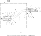
- Figure 2 depicts a second embodiment of the invention that differs from that of Figures 1A and 1B in that a flexible dielectric tube 28 is connected to one end of the cylinder 1 through the hole 20 in the wall 21 to supply the feed or reactant gas to the interior or plasma chamber within cylinder 1.
- This embodiment is otherwise similar to that of Figures 1A and 1B but is placed inside a larger vacuum chamber. The gas supply and manifold are fed in from outside the main vacuum chamber.
- the flexible gas tube 28 is connected through a vacuum feedthrough 26 to a gas control manifold 30 outside the vacuum chamber.
- the gas control manifold 30 has a gas on/off valve 32 and a device 34 to control gas flow rate into the chamber.
- Device 34 may be either an aperture or a gas flow control valve.
- a gas ballast 36 is located in the tube between the two valves 32 and 34 and serves to assist in igniting a plasma.
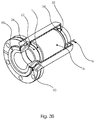
- Figures 3A and 3B illustrate a third embodiment of the invention in which the downstream end of cylinder 1 is sealed to a stainless steel or other metal tube or ring 50 that can be welded or brazed 22 to be made part of a ultra-high vacuum apparatus with all-metal seals or welds. No Viton or other elastomer vacuum seals are needed and the resulting apparatus can be "baked" or exposed to high temperature.
- Dielectric plasma cylinder 1 can be welded or brazed 22 to metal ring 24 and connected by flanges that allow a metal-to-metal seal for an ultra-high vacuum connection to the rest of the vacuum system with metal gaskets such as knife-edge copper gaskets 55.
- metal gaskets such as knife-edge copper gaskets 55.
- CF or ConFlat® (trademark of Agilent Technologies, Inc., 5301 Stevens Creek Boulevard, Santa Clara, California 95051) knife-edge copper-gasket-sealed flanges are preferred.
- Sealing ring 50 is connected by a metal ring 24 and braze seal 22 to cylinder 1. Sealing ring 50 is compressed by a rotating bolt ring 52.
- a metal ring 24 is welded or brazed 22 to cylinder 1.
- the gas feed entrance 20 may be located at any location on the baseplate 54 but the gas will be fed into the most intense portion of the plasma if it is in the center, to feed on the central axis of the plasma chamber 1.
- a ground shield 12 is located between the baseplate 54 and rotating ring 52. The electrode 4 and the ground shield 12 are isolated from each other by an insulator 14. The gas feed and RF inputs are described in the first embodiment Figure 1 and the other figure numbers correspond.
- the RF electrode on the outside 14 and ground shield 12 can be removable half shells and surround the dielectric tube plasma chamber and electrode, respectively.
- the RF connection 6 with cable 8 should be a simple pin type to allow the RF cable to be removed.
- the valve 32 must have metal seals and be bakeable. The rest of the gas manifold and connections can be attached to valve 32 via a metal swage seal fitting or a copper gasket connector.
- Figure 4 is a comparison of plasma density as measured by hydrocarbon removal rates with air plasma made in a quartz tube versus a Macor® tube as the dielectric 1 tube inside the external hollow cathode 4. Measurements were made in a 50L vacuum chamber, using a quartz crystal monitor or microbalance (QCM) to measure deposition rates at 15 cm from the wall port (25 cm from the plasma source). Chamber pressure (in the 50L vacuum chamber and interior of cylinder 1) during plasma operations was 1.06 x 10⁻³ Torr, and the flow rate through cylinder 1 was 12 sccm. RF power was as marked on the graph. The most resistant material to sputtering was found in Macor® machinable ceramic made by Corning Inc.
- QCM quartz crystal monitor or microbalance
- Quartz has been used in plasma chambers for ICP type plasma sources to separate the plasma from the electrode.
- hollow cathode plasma at 50 Watts tended to damage a quartz tube and create a white powder in the chamber.
- the Macor® ceramic tube showed no such damage after a longer exposure.
- Macor® ceramic emits more secondary electrons than quartz. This allows a Macor® tube to sustain a higher density plasma than a quartz tube, resulting in a higher cleaning rate. While Macor® ceramic exhibits unexpected results in the cylinder of the cathode of the invention, other dielectric materials are suitable for, and within the scope of, the present invention.
Landscapes
- Physics & Mathematics (AREA)
- Engineering & Computer Science (AREA)
- Plasma & Fusion (AREA)
- Chemical & Material Sciences (AREA)
- Analytical Chemistry (AREA)
- Spectroscopy & Molecular Physics (AREA)
- Electromagnetism (AREA)
- Fluid Mechanics (AREA)
- Optics & Photonics (AREA)
- Mechanical Engineering (AREA)
- Plasma Technology (AREA)
Description
- The present invention relates to an improved device for the plasma generation of oxygen radicals from air for use in cleaning analytical instruments such as scanning microscopes (SEM), scanning electron microprobes, transmission electron microscopes (TEM) and other charged-particle beam instruments that are subject to contamination problems from hydrocarbons. In particular, it relates to apparatus using a radio-frequency-excited hollow cathode (RF-HC) outside a vacuum container to create an excited gas plasma inside the vacuum container so that it becomes a plasma radical source.
- Traditionally, contamination control in vacuum systems such as scanning electron microscopes (SEMs) has focused on pump oils, finger prints, dirty specimens, and improper vacuum practices in manufacturing and operation. The use of dry pumps at all stages of the vacuum system of new field emission (FE) SEMs, and the use of better vacuum practices on the part of users and manufacturers have made environmental hydrocarbons, the hydrocarbon background contamination of our world, a significant source of the remaining hydrocarbons in electron microscope vacuum systems. These environmental sources of hydrocarbons (HC) cause a loss of resolution and contrast in imaging at the highest levels of magnification.
- The semiconductor industry and associated nano-sciences have created a demand for instruments that can image structures less than 5nm in size at less than 2KV. Instrument manufacturers have responded with field emission (FE) instruments that offer better than 400K× magnification at high contrast with low KV beams. Control of contamination has become more important as semiconductor manufacturers move to ever smaller dimensions. It is already common to examine features less than 10nm in size with low KV (<2KV) that are close to the resolution limits of the instruments. In such cases, the smallest amount of HC in the chamber can cause a loss of resolution and contrast. The electron beam reacts with any stray HC in the beam path or on the surface to create HC ions that then condense and form a hydrocarbon deposit on the area being scanned. Despite dry pumps and liquid nitrogen traps, these artifacts and contamination haze continue to be formed.
- Plasma cleaning with an air plasma removes hydrocarbons with a chemical etch where the oxygen in air is disassociated into neutral O radicals (atoms) or metastables. These species react quickly with hydrocarbons to produce H2O, CO2, CO, H2CO, and other short chain volatile hydrocarbons that can be removed by the vacuum pumps. Hydrogen gas can also be used in a plasma for cleaning by reduction of the hydrocarbons. Other frequently used gases include combinations of N2, O2, H2, fluorocarbons, as well as inert dilutant gasses He, Ne, Ar, Ne, and Xe.
- The most common method of plasma cleaning is to use an inductively coupled plasma (ICP) remote source or a remote microwave cavity. The ICP uses a radio-frequency-powered (RF) solenoid magnetic field to trap the electrons in the plasma. Because the ICP coil is grounded on one leg, it has low impedance and high current with high heating. The electron energy spread expands due to colliding and circling electrons in the magnetic field without encounters with the sheath. This results in more heating of the gas rather than ionization and disassociation of the molecules.
- It is well-known that a solenoid coil can be wrapped around a glass or quartz cylinder and excited with RF power to create an inductively coupled plasma or ICP without the electrode contacting the plasma. The ICP creates a magnetic field within the chamber that traps the free electrons within the coil while they oscillate..
U.S. Patent 3,616,461 to Gorin described an ICP electrodeless discharge in 1969. The hollow coil used by ICP magnetic confinement that confines electrons with an oscillating electric field is sometimes confused with an RF-excited hollow cathode (RF-HC). - The RF-excited hollow cathode is different from other plasma excitation methods. The hollow cathode is a symmetric chamber, ideally a cylindrical sheath with the same potential on all sides. Electrons inside the plasma are excited at RF frequency to oscillate between sides of the sheath and are accelerated inward only to be turned back by the opposite side of the sheath. This creates an electron trap to maintain the plasma. Electrons are created when molecules are ionized by electron collisions or by secondary electrons when ions hit the walls of the chamber. Electrons in the interior oscillate between the equal potentials of the circular sheath surrounding them The mathematical models for this behavior are discussed in the references Soderstrom, Modelling and Applications of the Hollow Cathode Plasma, Digital Summaries of Uppsala Dissertations INSN 16510-6214, IBSN 978-91-554-7206-1; Castillo, et al., Low-Pressure DC Air Plasmas. Investigation of Neutral and Ion Chemistry, The Journal Of Physical Chemistry A 109(28):6255-63, August 2005; and Han, et al., PIC/MMC Simulation of Radio Frequency Hollow Cathode Discharge in Nitrogen, Plasma Science and Technology, Vol. 18, No. 1, p. 72 Jan 2016.
- Han, et al. developed a two-dimensional PCC/MCC model to simulate the nitrogen radio frequency hollow cathode discharge (RF-HCD) plasma. It was found that both the sheath oscillation heating and secondary electron heating play a role to maintain the RF-HCD plasma under the simulated conditions. The mean energy of ions (N2 +, N+) in the negative glow region is greater than the thermal kinetic energy on the molecular gas (N2) which is an important characteristic of RF-HCD. During the negative portion of the hollow cathode voltage cycle, electrons mainly follow pendulum movement and produce a large number of ionization collisions in the plasma region. The heavier ions are accelerated into the walls and then produce secondary electrons that sustain the plasma. During the positive voltage of the RF cycle, the axial electric field becomes stronger and its direction points to the anode via the axial electric field acceleration. The pendulum motion of the electron through the axis of the hollow cathode makes the axis of the cylinder act like a virtual anode that is at neutral with the RF oscillations of the surrounding cathode driven by the RF source. It has been seen in our laboratory that a hollow cathode will generate and ignite plasma even without any nearby grounded surface except the outside vacuum chamber walls. A grid of holes in a sheet screen can be used as a plasma source electrode by functioning as multiple hollow cathodes.
- The cylindrical electrode is a hollow cathode and a cylindrical sheath forms around the inside. Secondary electrons may be emitted from the inner surface of the electrode or from a dielectric surface inside the electrode. The electrons are accelerated into the sheath and then are repelled by the sheath on the opposite side of the cylinder and are trapped to oscillate between the opposite sides of the sheath. These electrons cause a very high level of ionization in the gas and a very dense plasma. In the RF mode this plasma is characterized by a very low impedance, allowing a high effective current flow at relatively modest power levels. The low impedance is also characterized by a low voltage on the electrode.
- One of the major differences in RF-HC and other plasmas is that there is considerable electron and ion energy within the plasma due to the pendulum motion of the electrons towards the sheath in two different energy groups, secondary emitted electrons from the outside cylinder accelerated through the sheath and lower energy electrons from ionization inside the plasma.
- In the hollow cathode there is a virtual anode on the axis of the cylinder that is neutral in regards to the RF field on the surrounding cathode. Thus there is no physical anode sheath in the center. As shown in the above-referenced papers, modeling the RF-HC plasma shows that high energy ions gather on axis to oscillate at high energy and are slowed down by collisions with molecules, collisions which produce more ions and electrons.
- In operation, on both ends of this RF-HC, the plasma sheath extends out like a tongue from the cylinder into the surrounding vacuum. Most of the theory on sheaths has only been on sheaths near surfaces. It is our speculation that the plasma extension tongue is sustained by the projected ions along the axis until the ions are neutralized and run out of energy from collisions with molecules in the vacuum. The distance traveled by these ions will depend on pressure, the mean free path, and the average energy lost per collision. The surrounding chamber, if conducting, provides the needed reference ground potential but does not interact with the plasma sheath directly.
- If a solid surface intersects with the plasma tongue a classic sheath will develop and the ions will collide with the solid surface. At high enough ion energies sputtering can occur on this surface. Sputtering can be avoided if the distance from the solid surface is increased so that the plasma tongue does not form a sheath next to it.
- Commonly invented
U.S. Patents 6,105,589 ,6,452,315 and6,610,252 to Vane describe the RF-HCD remote plasma apparatus and method developed for remote cleaning of scanning electron microscopes using a hollow cathode made from an aluminum screen made by machining or from punched sheet metal. This device was successful but experience with it showed that improvements could be made. The aluminum cylindrical hollow cathode is immersed in the plasma during operation. At low power (<20 Watts RF @13.56 MHz) this created few problems, but at higher power, overheating and electrode erosion occurred and discoloration formed on the interior walls of the plasma source. This suggested material losses from the electrode and its support structure. The RF power was fed through a power feedthrough on the flange which supported the electrode on its axis via a support cross bar. All of these parts were in the prior art plasma radical source, and they displayed erosion damage over long exposure at higher power. - An apparatus for cleaning a substrate in a reactive ion etch process is disclosed in
US2006054279 (A1 ). The apparatus is configured to produce an atmospheric plasma using a RF generation device. The apparatus includes a plasma forming chamber including a cavity defined by a set of interior chamber walls comprised of a dielectric material. The apparatus also includes an atmospheric plasma generated by the RF generation device, the atmospheric plasma protruding from a first end of the cavity to clean the substrate. - A plasma process method and apparatus for use with a vacuum instrument, having a vacuum chamber evacuated by an oil free high vacuum pump to a base pressure below about 1 Pa, is disclosed in
US2015097485 (A1 ). A gas buffer chamber is in fluid communication with the plasma chamber, the gas buffer chamber having a volume about 1/500 to 1/2000 of the volume of the vacuum chamber. A valve between the plasma chamber and the gas chamber permits flow between the gas chamber and the plasma chamber, wherein, upon opening the valve, gas is admitted into the plasma chamber and pressure in the plasma chamber rises temporarily to between about 10 and about 200 Pa and plasma ignition can be obtained when the plasma excitation device is energized simultaneously. A flow restriction between the gas source and the gas chamber has a maximum flow rate therethrough of about 25 sccm. (standard cubic centimeters per minute) or less so that pressure in the plasma chamber remains between about 1 and about 7 Pa after plasma ignition to maintain plasma conduction and to avoid overloading or heating of the high vacuum pump. - It is a general object of the present invention compared to prior art to modify the plasma source to avoid damaging sputtering inside the chamber and to raise the power of an RF hollow cathode electrode discharge to enable low voltage, high current operation to prevent overheating, erosion of the electrode, and particulate generation. Accordingly, several steps are taken to modify the source:
- 1. Move the hollow cathode electrode outside the vacuum plasma chamber of the instrument.
- 2. Make the vacuum plasma chamber a cylinder of dielectric insulation material that is resistant to sputtering.
- 3. Create the conductive electrode as a cylinder around the insulating material.
- 4. Move the ends of the chamber beyond the ends of the plasma sheath along the axis of the cylinder.
- 5. Adjust the length of the mean free path by adjusting the operating pressure so that the chamber ends are not touched by the plasma sheath to prevent ion sputtering of the chamber ends.
- 6. Supply a source of gas to the plasma chamber and have the gas exit into the main vacuum chamber after excitation.
- An aspect of the invention is set out according to appended
claim 1. Embodiments of the invention are set out according to the appended dependent claims. - The hollow cathode electrode is mounted around a vacuum chamber made of an insulating dielectric material. This design removes the conductive material of the electrode from contact with ions from the plasma and sheath. The plasma chamber and electrode are then mounted inside an outer grounded shell for electrical safety. The gas exits the plasma chamber at the end of the shell via a vacuum flange into the main chamber of the instrument or tool to be cleaned. The plasma itself inside its sheath is contained mainly inside the cylinder or plasma chamber. The sheath will exhibit a tongue that will extend into the main chamber. The size of the tongue is governed by the applied RF power and the mean free path of the gas in vacuum. With some gases and gas mixtures at low pressures, a flowing afterglow will be exhibited outside the sheath in the chamber. This afterglow is generated by the decay of metastables in the out-flowing gas. With air, the afterglow has a distinct violet color at 386 nm caused by the decay of an N2 Δ1metastable. This color is often mistakenly described as pink. The atomic oxygen metastable is only weakly visible and is hard to see mixed with N2. Cleaning measurements show the nitrogen afterglow is a marker for the volume being cleaned by oxygen. Because there is no conductive material such as aluminum near the plasma sheath, the production of metal particulates like alumina is suppressed.
- In a preferred embodiment of the invention, the reactant gas is air because it is a convenient source of oxygen. Other oxygen gas mixtures and pure oxygen can be used or reducing gas can be used. These mixtures can contain hydrogen, water vapor, He, Ar, Ne, F and compounds thereof. For cleaning by reduction H2 and ammonia could be used. The requirement is that reactions with the contaminant produce a volatile compound that can be removed by the pumps when the contamination reacts with plasma activated radicals or metastables.
- With an exterior hollow cathode, the dielectric cylinder will partially enclose and define the plasma sheath, which will make a cylindrical shape inside. Ions will create secondary electrons when they collide with the diaelectric material and the expelled ions will be accelerated into the plasma by the sheath. Inside the plasma the high energy ions are very effective in ionization and disassociation of the gas molecules.
-
-
Figure 1A is a longitudinal section view of an embodiment of the present invention; -
Figure 1B is a perspective view, partially in section, of the embodiment ofFigure 1A ; -
Figure 2 is a perspective view of another embodiment of the present invention; -
Figure 3A is a longitudinal section view of still another embodiment of the present invention; -
Figure 3B is a perspective view, partially in section, of the embodiment ofFigure 3A ; and -
Figure 4 is a graphical comparison of data showing that Macor® ceramic produces a denser plasma than quartz when it is used as thedielectric cylinder 1. - Reference Numerals in Drawings
dielectric cylinder or tube 1metal ring or tube connected to seal 24 plasma 2vacuum feedthrough 26 hollow cathode electrode 4flexible gas tube 28center conductor 6manifold 30coaxial cable 8 on/off valve 32RF impedance match 9 gas control device 34vacuum seal o- rings 10gas ballast 36KF flange O- ring 11chamber exit flange 40conductive grounded shield 12connector flange 42insulator 14sealing CF joint with knife edge 50activated gas 16rotating ring 52gas entrance hole 20baseplate 54tube end wall 21copper ring 55metal welded or brazed seal 22CF connector flange 56 - Referring now to the Figures and in particular to
Figures 1A and1B , a first embodiment of the plasma device according to the present invention comprises ahollow cylinder 1 made of a dielectric material such as the machinable ceramic composed of about 55% fluorophlogopite mica and 45% borosilicate glass and sold under the trademark Macor® by Corning Incorporated, Houghton Park CB-08, Corning, New York 14831.Cylinder 1 is in fluid communication at its downstream end with the vacuum chamber of an instrument and thus is itself under vacuum conditions and is used to contain aplasma 2 in a plasma chamber defined in the interior of thecylinder 1. Other dielectric materials such glass, quartz, Teflon, and other ceramics were tested and it was found that they did not produce as dense a plasma as the Macor® ceramic (see discussion in connection withFigure 4 , below). While Macor® ceramic material provided unexpectedly good results, the other materials listed above, as well as other dieletric materials, may also be suitable for use in the present invention. - A
hollow cathode electrode 4, made from a conductive material such as brass, is placed around and in close contact withcylinder 1.Electrode 4 may be a machined cylinder that is placed around the exterior ofcylinder 1 or a thin sheet of conductor wrapped aroundcylinder 1.Electrode 4 may also be "assembled" of halves or quarters machined or otherwise formed from electrically conductive metals or other conductive materials that are closely joined together, electrically, physically, or structurally, upon assembly.Electrode 4 is intended to be a continuous thin conductive cylinder, as distinguished from a coil or other interrupted structure, to avoid inductive coupling effects. Other conductive materials such as aluminum or copper could also be used for the electrode. Theelectrode 4 is connected to thecenter conductor 6 of a 50-Ohm coaxial cable 8 that carries radio-frequency (RF) power (∼3KHz to 300GHz) to the electrode from an RF impedence matching network 9. - A cylindrical, electrically
conductive shield 12 is placed around theelectrode 4 and is electrically grounded. Vacuum seal O-rings 10 are used so that theplasma chamber 2 is under vacuum and theelectrode 4 is at atmospheric pressure.Shield 12 is grounded by a connection to the shield of the RF cable 8 (not shown). The shield also provides an RF ground for theplasma 2 by being in contact withceramic cylinder 1 on either of the ends extending beyond theelectrode insulation 14. Aninsulator 14 in the form of an air gap (as shown), or solid dielectric material, separateselectrode 4 fromshield 12. Between the O-rings 10 and theelectrode 4, the groundedcylinder 12 may make contact withcylinder 1. - In this embodiment, an upstream end of
cylinder 1 has a gas entrance aperture orhole 20 through anend wall 21 in communication with a source or supply of gas to supply the feed or reactant gas to the interior ofcylinder 1 to generate and maintain a plasma.End wall 21 should be placed by empirical design away from the intense (brightest)plasma 2 region inside the hollow cathode ofcylinder 1 to avoid ion bombardment damage to the end wall. - The feed gas is fed through a
gas manifold 30 that contains an on/offvalve 32 to control the entrance of gas intochamber 2 and a device for controlling the gas flow or leak rate to and throughaperture 20. The leak rate of gas throughaperture 20 into the interior ofcylinder 1 may be a fixed rate through a gasrate control device 34, such as an orifice or a variable opening or needle or other metering valve that may be controlled manually, or may be varied by a feedback method that uses pressure, plasma density, optical spectra, reaction rate, current, or other physical properties of the plasma to adjust flow. The gas feed pressure to therate control device 34 is at atmospheric pressure or an otherwise controlled higher pressure. A volume of gas called thegas ballast 36 exists in the manifold tube betweenvalves valve 32 is closed) and drops suddenly whenvalve 32 is opened, causing a short-duration gas pressure burst downstream inplasma chamber 2, which assists in igniting a plasma. This gas burst technique follows the disclosures of Vane inU.S. Patent Publication 2015-0097485 and Williamson inU.S. Patent Nos. 4,800,282 and4,977,353 .
An exit end 40 of theplasma chamber 2 is attached to aconnector flange 42 that connects to the main vacuum chamber of the instrument. Typically, KF (or QF) clamp flanges are used with an O-ring 11 mounted on a centering ring (not shown). The activatedgas particles 16 from theplasma chamber 2 flow into the connected main vacuum chamber to clean it or accomplish other downstream processes. - In the preferred embodiments, a fixed-flow-rate orifice is used as a gas flow-
rate control device 34. Experiments have shown that cleaning at the pressures achieved by turbo- molecular pumps (TMP), acting on instrument vacuum chambers in the range of between 1 milliTorr and 30 milliTor, provides satisfactory cleaning rates, and that the flow rate into the plasma chamber of reactant gas is more important than the measured pressure. Thus, a fixed flow rate of 5 to 40 standard cubic centimeters per minute (sccm) satisfies and maintains these conditions both for generation of plasma and flow of and cleaning with the plasma subsequent to generation. By providing fixed input gas flow rate to any TMP system, a plasma can usually be ignited by an RF-Hollow Cathode described in this invention regardless of the pumping speed except in extreme cases. -
Figure 2 depicts a second embodiment of the invention that differs from that ofFigures 1A and1B in that aflexible dielectric tube 28 is connected to one end of thecylinder 1 through thehole 20 in thewall 21 to supply the feed or reactant gas to the interior or plasma chamber withincylinder 1. This embodiment is otherwise similar to that ofFigures 1A and1B but is placed inside a larger vacuum chamber. The gas supply and manifold are fed in from outside the main vacuum chamber. - The
flexible gas tube 28 is connected through a vacuum feedthrough 26 to agas control manifold 30 outside the vacuum chamber. Thegas control manifold 30 has a gas on/offvalve 32 and adevice 34 to control gas flow rate into the chamber.Device 34 may be either an aperture or a gas flow control valve. Agas ballast 36 is located in the tube between the twovalves flexible tube 28 and RF cable 8 tether, this embodiment may be placed anywhere in the vacuum system where plasma cleaning or carbon removal is needed. -
Figures 3A and3B illustrate a third embodiment of the invention in which the downstream end ofcylinder 1 is sealed to a stainless steel or other metal tube orring 50 that can be welded or brazed 22 to be made part of a ultra-high vacuum apparatus with all-metal seals or welds. No Viton or other elastomer vacuum seals are needed and the resulting apparatus can be "baked" or exposed to high temperature. -
Dielectric plasma cylinder 1 can be welded or brazed 22 tometal ring 24 and connected by flanges that allow a metal-to-metal seal for an ultra-high vacuum connection to the rest of the vacuum system with metal gaskets such as knife-edge copper gaskets 55. CF or ConFlat® (trademark of Agilent Technologies, Inc., 5301 Stevens Creek Boulevard, Santa Clara, California 95051) knife-edge copper-gasket-sealed flanges are preferred. Sealingring 50 is connected by ametal ring 24 and brazeseal 22 tocylinder 1. Sealingring 50 is compressed by arotating bolt ring 52. At the upstream or gas-entrance end oftube 1, ametal ring 24 is welded or brazed 22 tocylinder 1. Thegas feed entrance 20 may be located at any location on thebaseplate 54 but the gas will be fed into the most intense portion of the plasma if it is in the center, to feed on the central axis of theplasma chamber 1. Aground shield 12 is located between thebaseplate 54 and rotatingring 52. Theelectrode 4 and theground shield 12 are isolated from each other by aninsulator 14. The gas feed and RF inputs are described in the first embodimentFigure 1 and the other figure numbers correspond. The RF electrode on the outside 14 andground shield 12 can be removable half shells and surround the dielectric tube plasma chamber and electrode, respectively. TheRF connection 6 with cable 8 should be a simple pin type to allow the RF cable to be removed. Thevalve 32 must have metal seals and be bakeable. The rest of the gas manifold and connections can be attached tovalve 32 via a metal swage seal fitting or a copper gasket connector. -
Figure 4 is a comparison of plasma density as measured by hydrocarbon removal rates with air plasma made in a quartz tube versus a Macor® tube as the dielectric 1 tube inside the externalhollow cathode 4. Measurements were made in a 50L vacuum chamber, using a quartz crystal monitor or microbalance (QCM) to measure deposition rates at 15 cm from the wall port (25 cm from the plasma source). Chamber pressure (in the 50L vacuum chamber and interior of cylinder 1) during plasma operations was 1.06 x 10⁻³ Torr, and the flow rate throughcylinder 1 was 12 sccm. RF power was as marked on the graph. The most resistant material to sputtering was found in Macor® machinable ceramic made by Corning Inc. Quartz has been used in plasma chambers for ICP type plasma sources to separate the plasma from the electrode. We found that hollow cathode plasma at 50 Watts tended to damage a quartz tube and create a white powder in the chamber. The Macor® ceramic tube showed no such damage after a longer exposure. In addition, Macor® ceramic emits more secondary electrons than quartz. This allows a Macor® tube to sustain a higher density plasma than a quartz tube, resulting in a higher cleaning rate. While Macor® ceramic exhibits unexpected results in the cylinder of the cathode of the invention, other dielectric materials are suitable for, and within the scope of, the present invention. - In the development of the first embodiment of the invention it was observed that no significant plasma self-bias voltage could be observed between the RF
hollow cathode 4 and thechamber ground 12. Because there is no conductive plasma path between the two due to thedielectric cylinder 1 inside the anode, this was not surprising, but it indicates a significant unusual property of the invention. The plasma oscillates about a virtual ground anode on the axis of thehollow cathode assembly - The invention has been described in connection with preferred and illustrative embodiments thereof. It is thus not limited, but is susceptible to variation and modification without departing from the scope of the invention, which is defined in the appended claims.
Claims (10)
- A device for the production of plasma using a radio-frequency hollow cathode discharge configured to deliver reactive particles to a vacuum chamber, the device comprising said vacuum chamber;a) a hollow cylinder (1) formed of a dielectric material, the cylinder (1) defining in its interior a plasma chamber and having an exterior diameter and an upstream end in communication with a source of gas through a gas flow control device (34);b) a single cylindrical electrode (4) formed of conducting material and surrounding the exterior of the cylinder (1), the electrode (4) in communication with a source of radio-frequency electrical power, wherein, in use, upon energizing the electrode (4) with radio-frequency electric power and passage of gas through the cylinder (1), a plasma is formed inside the dielectric cylinder (1) to generate the reactive particles; and characterized in thatc) said vacuum chamber is in fluid communication with a downstream end of the hollow cylinder (1), which is thus, in use, itself under vacuum conditions.
- The device of any preceding claim, wherein the cylinder (1) is formed of a material comprising about 55% fluorophlogopite mica and 45% borosilicate glass.
- The device of any preceding claim, wherein the vacuum chamber is the vacuum chamber of a charged-particle-beam instrument.
- The device of claim 3, wherein the gas is air and the device is configured to deliver oxygen radicals to the vacuum chamber for removing carbon compounds by oxidation from the vacuum chamber.
- The device of any one of claims 1-3, wherein the gas is hydrogen.
- The device of any preceding claim, wherein the opposing end of the cylinder (1) is closed by an end wall (21) formed of the dielectric material and the gas enters through a hole in the end wall.
- The device of any preceding claim, wherein a virtual anode is formed by the hollow cathode effect along a central axis of the cylinder (1) in the plasma and a ground is defined by the vacuum chamber walls.
- The device of any preceding claim, wherein the cylindrical electrode (4) is a brass cylinder around the exterior diameter of the hollow cylinder (1).
- The device of any preceding claim, wherein the gas flow control device (34) includes an aperture (20).
- The device of any preceding claim, wherein the gas flow control device is a variable valve (32).
Applications Claiming Priority (1)
| Application Number | Priority Date | Filing Date | Title |
|---|---|---|---|
| US15/612,232 US10468236B2 (en) | 2017-06-02 | 2017-06-02 | Plasma device with an external RF hollow cathode for plasma cleaning of high vacuum systems |
Publications (2)
| Publication Number | Publication Date |
|---|---|
| EP3410462A1 EP3410462A1 (en) | 2018-12-05 |
| EP3410462B1 true EP3410462B1 (en) | 2021-03-24 |
Family
ID=62386036
Family Applications (1)
| Application Number | Title | Priority Date | Filing Date |
|---|---|---|---|
| EP18174141.4A Active EP3410462B1 (en) | 2017-06-02 | 2018-05-24 | Plasma device with an external rf hollow cathode for plasma cleaning of high vacuum systems |
Country Status (3)
| Country | Link |
|---|---|
| US (2) | US10468236B2 (en) |
| EP (1) | EP3410462B1 (en) |
| DK (1) | DK3410462T3 (en) |
Families Citing this family (9)
| Publication number | Priority date | Publication date | Assignee | Title |
|---|---|---|---|---|
| WO2019058511A1 (en) * | 2017-09-22 | 2019-03-28 | 住友重機械工業株式会社 | Ion source device |
| NL2022156B1 (en) * | 2018-12-10 | 2020-07-02 | Asml Netherlands Bv | Plasma source control circuit |
| CN110798958B (en) * | 2019-11-04 | 2024-07-09 | 合肥杰硕真空科技有限公司 | Device for discharging plasma of annular electrode in circular cavity |
| US11415538B2 (en) * | 2020-03-06 | 2022-08-16 | Applied Materials, Inc. | Capacitive sensor housing for chamber condition monitoring |
| CH718504A2 (en) * | 2021-03-31 | 2022-10-14 | Inficon ag | Vacuum feedthrough, electrode arrangement, device for generating a silent plasma discharge, measuring device and method for its operation. |
| DE102021111097B4 (en) * | 2021-04-29 | 2023-04-06 | Fraunhofer-Gesellschaft zur Förderung der angewandten Forschung eingetragener Verein | Hollow cathode system for generating a plasma and method for operating such a hollow cathode system |
| CN113357114B (en) * | 2021-07-19 | 2022-05-06 | 哈尔滨工业大学 | A kind of assembly structure and assembly method of main cathode applied to thruster |
| CN115971169B (en) * | 2023-02-24 | 2023-07-07 | 深圳市方瑞科技有限公司 | Drum-type vacuum plasma cleaning machine and working method thereof |
| KR102937941B1 (en) * | 2024-07-19 | 2026-03-10 | 서울대학교산학협력단 | Device for feeding electrons with low energy |
Family Cites Families (19)
| Publication number | Priority date | Publication date | Assignee | Title |
|---|---|---|---|---|
| US3627663A (en) * | 1968-03-25 | 1971-12-14 | Ibm | Method and apparatus for coating a substrate by utilizing the hollow cathode effect with rf sputtering |
| US3616461A (en) | 1969-12-05 | 1971-10-26 | Lfe Corp | Apparatus for exciting a gas by means of an electrodeless discharge |
| US4800281A (en) | 1984-09-24 | 1989-01-24 | Hughes Aircraft Company | Compact penning-discharge plasma source |
| US4800282A (en) | 1985-02-07 | 1989-01-24 | Sharp Kabushiki Kaisha | Apparatus and method for detecting residual organic compounds |
| US4977352A (en) | 1988-06-24 | 1990-12-11 | Hughes Aircraft Company | Plasma generator having rf driven cathode |
| US4977353A (en) | 1989-08-31 | 1990-12-11 | Minitronics Pty Limited | Communication system for single point emergency lighting |
| US6112696A (en) | 1998-02-17 | 2000-09-05 | Dry Plasma Systems, Inc. | Downstream plasma using oxygen gas mixture |
| DE69929271T2 (en) * | 1998-10-26 | 2006-09-21 | Matsushita Electric Works, Ltd., Kadoma | Apparatus and method for plasma treatment |
| US6105589A (en) * | 1999-01-11 | 2000-08-22 | Vane; Ronald A. | Oxidative cleaning method and apparatus for electron microscopes using an air plasma as an oxygen radical source |
| US6610257B2 (en) | 1999-01-11 | 2003-08-26 | Ronald A. Vane | Low RF power electrode for plasma generation of oxygen radicals from air |
| US6452315B1 (en) | 2000-02-08 | 2002-09-17 | Ronald A. Vane | Compact RF plasma device for cleaning electron microscopes and vacuum chambers |
| US6566144B1 (en) | 2000-03-27 | 2003-05-20 | Atrix Laboratories | Cover plate for use in lyophilization |
| US6685803B2 (en) | 2001-06-22 | 2004-02-03 | Applied Materials, Inc. | Plasma treatment of processing gases |
| JP2005033173A (en) * | 2003-06-16 | 2005-02-03 | Renesas Technology Corp | Manufacturing method of semiconductor integrated circuit device |
| US7479157B2 (en) * | 2003-08-07 | 2009-01-20 | Boston Scientific Scimed, Inc. | Stent designs which enable the visibility of the inside of the stent during MRI |
| US20060054279A1 (en) * | 2004-09-10 | 2006-03-16 | Yunsang Kim | Apparatus for the optimization of atmospheric plasma in a processing system |
| WO2010107722A1 (en) | 2009-03-16 | 2010-09-23 | Drexel University | Tubular floating electrode dielectric barrier discharge for applications in sterilization and tissue bonding |
| JP5764433B2 (en) * | 2011-08-26 | 2015-08-19 | 株式会社日立ハイテクノロジーズ | Mass spectrometer and mass spectrometry method |
| US20150097485A1 (en) | 2013-10-08 | 2015-04-09 | XEI Scientific Inc. | Method and apparatus for plasma ignition in high vacuum chambers |
-
2017
- 2017-06-02 US US15/612,232 patent/US10468236B2/en active Active
-
2018
- 2018-05-24 EP EP18174141.4A patent/EP3410462B1/en active Active
- 2018-05-24 DK DK18174141.4T patent/DK3410462T3/en active
-
2019
- 2019-10-15 US US16/601,935 patent/US20200058472A1/en not_active Abandoned
Non-Patent Citations (1)
| Title |
|---|
| None * |
Also Published As
| Publication number | Publication date |
|---|---|
| EP3410462A1 (en) | 2018-12-05 |
| DK3410462T3 (en) | 2021-04-19 |
| US20200058472A1 (en) | 2020-02-20 |
| US20180350564A1 (en) | 2018-12-06 |
| US10468236B2 (en) | 2019-11-05 |
Similar Documents
| Publication | Publication Date | Title |
|---|---|---|
| US10468236B2 (en) | Plasma device with an external RF hollow cathode for plasma cleaning of high vacuum systems | |
| US5961772A (en) | Atmospheric-pressure plasma jet | |
| US6610257B2 (en) | Low RF power electrode for plasma generation of oxygen radicals from air | |
| Selwyn et al. | Materials Processing Using an Atmospheric Pressure, RF‐Generated Plasma Source | |
| Conrads et al. | Plasma generation and plasma sources | |
| US6452315B1 (en) | Compact RF plasma device for cleaning electron microscopes and vacuum chambers | |
| US9142388B2 (en) | Capacitively coupled remote plasma source | |
| EP2256781B1 (en) | Toroidal Plasma Chamber | |
| Benedikt et al. | Quadrupole mass spectrometry of reactive plasmas | |
| US5996528A (en) | Method and apparatus for flowing gases into a manifold at high potential | |
| KR102023828B1 (en) | Processing apparatus and processing method, and gas cluster generating apparatus and generating method | |
| WO2010082561A1 (en) | Apparatus and method for producing plasma | |
| Kaeppelin et al. | Different operational regimes in a helicon plasma source | |
| CN106575598B (en) | Plasma cleaning of mass spectrometer | |
| TWI402001B (en) | Plasma processing device, plasma processing method, and processed object treated by the method | |
| CN1290399A (en) | Device for producing excited/ionized particles in plasma | |
| JP3631269B2 (en) | Excited oxygen supply method | |
| JP2001148340A (en) | Charged particle beam exposure method and apparatus | |
| Amemiya et al. | Multicusp type electron cyclotron resonance ion source for plasma processing | |
| JP2001192829A (en) | Ecr plasma enhanced cvd system for carbon nanotube thin film deposition, and method of deposition for the thin film | |
| Korzec et al. | Influence of the substrate surface on ion concentrations in a large volume microwave plasma | |
| JPH06136544A (en) | Plasma treatment device | |
| WO2002078749A2 (en) | Atmospheric pressure rf plasma source using ambient air and complex molecular gases | |
| US20190333735A1 (en) | Plasma source and plasma processing apparatus | |
| Herschberg et al. | Design and operation of a vacuum plasma torch for contaminant removal |
Legal Events
| Date | Code | Title | Description |
|---|---|---|---|
| PUAI | Public reference made under article 153(3) epc to a published international application that has entered the european phase |
Free format text: ORIGINAL CODE: 0009012 |
|
| STAA | Information on the status of an ep patent application or granted ep patent |
Free format text: STATUS: THE APPLICATION HAS BEEN PUBLISHED |
|
| AK | Designated contracting states |
Kind code of ref document: A1 Designated state(s): AL AT BE BG CH CY CZ DE DK EE ES FI FR GB GR HR HU IE IS IT LI LT LU LV MC MK MT NL NO PL PT RO RS SE SI SK SM TR |
|
| AX | Request for extension of the european patent |
Extension state: BA ME |
|
| STAA | Information on the status of an ep patent application or granted ep patent |
Free format text: STATUS: REQUEST FOR EXAMINATION WAS MADE |
|
| 17P | Request for examination filed |
Effective date: 20190603 |
|
| RBV | Designated contracting states (corrected) |
Designated state(s): AL AT BE BG CH CY CZ DE DK EE ES FI FR GB GR HR HU IE IS IT LI LT LU LV MC MK MT NL NO PL PT RO RS SE SI SK SM TR |
|
| RIC1 | Information provided on ipc code assigned before grant |
Ipc: H01J 37/32 20060101AFI20200820BHEP Ipc: H05H 1/46 20060101ALI20200820BHEP Ipc: H05H 1/24 20060101ALI20200820BHEP |
|
| RIN1 | Information on inventor provided before grant (corrected) |
Inventor name: VANE, RONALD A. Inventor name: CABLE, MICHAEL Inventor name: SAFAR, GEORGE |
|
| GRAP | Despatch of communication of intention to grant a patent |
Free format text: ORIGINAL CODE: EPIDOSNIGR1 |
|
| STAA | Information on the status of an ep patent application or granted ep patent |
Free format text: STATUS: GRANT OF PATENT IS INTENDED |
|
| INTG | Intention to grant announced |
Effective date: 20201009 |
|
| GRAS | Grant fee paid |
Free format text: ORIGINAL CODE: EPIDOSNIGR3 |
|
| GRAA | (expected) grant |
Free format text: ORIGINAL CODE: 0009210 |
|
| STAA | Information on the status of an ep patent application or granted ep patent |
Free format text: STATUS: THE PATENT HAS BEEN GRANTED |
|
| AK | Designated contracting states |
Kind code of ref document: B1 Designated state(s): AL AT BE BG CH CY CZ DE DK EE ES FI FR GB GR HR HU IE IS IT LI LT LU LV MC MK MT NL NO PL PT RO RS SE SI SK SM TR |
|
| REG | Reference to a national code |
Ref country code: GB Ref legal event code: FG4D |
|
| REG | Reference to a national code |
Ref country code: SE Ref legal event code: TRGR |
|
| REG | Reference to a national code |
Ref country code: CH Ref legal event code: EP |
|
| REG | Reference to a national code |
Ref country code: IE Ref legal event code: FG4D |
|
| REG | Reference to a national code |
Ref country code: DE Ref legal event code: R096 Ref document number: 602018014239 Country of ref document: DE Ref country code: AT Ref legal event code: REF Ref document number: 1375340 Country of ref document: AT Kind code of ref document: T Effective date: 20210415 |
|
| REG | Reference to a national code |
Ref country code: DK Ref legal event code: T3 Effective date: 20210414 |
|
| REG | Reference to a national code |
Ref country code: NL Ref legal event code: FP |
|
| REG | Reference to a national code |
Ref country code: NO Ref legal event code: T2 Effective date: 20210324 |
|
| REG | Reference to a national code |
Ref country code: LT Ref legal event code: MG9D |
|
| PG25 | Lapsed in a contracting state [announced via postgrant information from national office to epo] |
Ref country code: HR Free format text: LAPSE BECAUSE OF FAILURE TO SUBMIT A TRANSLATION OF THE DESCRIPTION OR TO PAY THE FEE WITHIN THE PRESCRIBED TIME-LIMIT Effective date: 20210324 Ref country code: FI Free format text: LAPSE BECAUSE OF FAILURE TO SUBMIT A TRANSLATION OF THE DESCRIPTION OR TO PAY THE FEE WITHIN THE PRESCRIBED TIME-LIMIT Effective date: 20210324 Ref country code: GR Free format text: LAPSE BECAUSE OF FAILURE TO SUBMIT A TRANSLATION OF THE DESCRIPTION OR TO PAY THE FEE WITHIN THE PRESCRIBED TIME-LIMIT Effective date: 20210625 Ref country code: BG Free format text: LAPSE BECAUSE OF FAILURE TO SUBMIT A TRANSLATION OF THE DESCRIPTION OR TO PAY THE FEE WITHIN THE PRESCRIBED TIME-LIMIT Effective date: 20210624 |
|
| PG25 | Lapsed in a contracting state [announced via postgrant information from national office to epo] |
Ref country code: RS Free format text: LAPSE BECAUSE OF FAILURE TO SUBMIT A TRANSLATION OF THE DESCRIPTION OR TO PAY THE FEE WITHIN THE PRESCRIBED TIME-LIMIT Effective date: 20210324 Ref country code: LV Free format text: LAPSE BECAUSE OF FAILURE TO SUBMIT A TRANSLATION OF THE DESCRIPTION OR TO PAY THE FEE WITHIN THE PRESCRIBED TIME-LIMIT Effective date: 20210324 |
|
| REG | Reference to a national code |
Ref country code: AT Ref legal event code: MK05 Ref document number: 1375340 Country of ref document: AT Kind code of ref document: T Effective date: 20210324 |
|
| PG25 | Lapsed in a contracting state [announced via postgrant information from national office to epo] |
Ref country code: LT Free format text: LAPSE BECAUSE OF FAILURE TO SUBMIT A TRANSLATION OF THE DESCRIPTION OR TO PAY THE FEE WITHIN THE PRESCRIBED TIME-LIMIT Effective date: 20210324 Ref country code: EE Free format text: LAPSE BECAUSE OF FAILURE TO SUBMIT A TRANSLATION OF THE DESCRIPTION OR TO PAY THE FEE WITHIN THE PRESCRIBED TIME-LIMIT Effective date: 20210324 Ref country code: CZ Free format text: LAPSE BECAUSE OF FAILURE TO SUBMIT A TRANSLATION OF THE DESCRIPTION OR TO PAY THE FEE WITHIN THE PRESCRIBED TIME-LIMIT Effective date: 20210324 Ref country code: AT Free format text: LAPSE BECAUSE OF FAILURE TO SUBMIT A TRANSLATION OF THE DESCRIPTION OR TO PAY THE FEE WITHIN THE PRESCRIBED TIME-LIMIT Effective date: 20210324 Ref country code: SM Free format text: LAPSE BECAUSE OF FAILURE TO SUBMIT A TRANSLATION OF THE DESCRIPTION OR TO PAY THE FEE WITHIN THE PRESCRIBED TIME-LIMIT Effective date: 20210324 |
|
| PG25 | Lapsed in a contracting state [announced via postgrant information from national office to epo] |
Ref country code: IS Free format text: LAPSE BECAUSE OF FAILURE TO SUBMIT A TRANSLATION OF THE DESCRIPTION OR TO PAY THE FEE WITHIN THE PRESCRIBED TIME-LIMIT Effective date: 20210724 Ref country code: PL Free format text: LAPSE BECAUSE OF FAILURE TO SUBMIT A TRANSLATION OF THE DESCRIPTION OR TO PAY THE FEE WITHIN THE PRESCRIBED TIME-LIMIT Effective date: 20210324 Ref country code: PT Free format text: LAPSE BECAUSE OF FAILURE TO SUBMIT A TRANSLATION OF THE DESCRIPTION OR TO PAY THE FEE WITHIN THE PRESCRIBED TIME-LIMIT Effective date: 20210726 Ref country code: SK Free format text: LAPSE BECAUSE OF FAILURE TO SUBMIT A TRANSLATION OF THE DESCRIPTION OR TO PAY THE FEE WITHIN THE PRESCRIBED TIME-LIMIT Effective date: 20210324 Ref country code: RO Free format text: LAPSE BECAUSE OF FAILURE TO SUBMIT A TRANSLATION OF THE DESCRIPTION OR TO PAY THE FEE WITHIN THE PRESCRIBED TIME-LIMIT Effective date: 20210324 |
|
| REG | Reference to a national code |
Ref country code: CH Ref legal event code: PL |
|
| REG | Reference to a national code |
Ref country code: DE Ref legal event code: R097 Ref document number: 602018014239 Country of ref document: DE |
|
| PG25 | Lapsed in a contracting state [announced via postgrant information from national office to epo] |
Ref country code: ES Free format text: LAPSE BECAUSE OF FAILURE TO SUBMIT A TRANSLATION OF THE DESCRIPTION OR TO PAY THE FEE WITHIN THE PRESCRIBED TIME-LIMIT Effective date: 20210324 Ref country code: MC Free format text: LAPSE BECAUSE OF FAILURE TO SUBMIT A TRANSLATION OF THE DESCRIPTION OR TO PAY THE FEE WITHIN THE PRESCRIBED TIME-LIMIT Effective date: 20210324 Ref country code: LI Free format text: LAPSE BECAUSE OF NON-PAYMENT OF DUE FEES Effective date: 20210531 Ref country code: LU Free format text: LAPSE BECAUSE OF NON-PAYMENT OF DUE FEES Effective date: 20210524 Ref country code: AL Free format text: LAPSE BECAUSE OF FAILURE TO SUBMIT A TRANSLATION OF THE DESCRIPTION OR TO PAY THE FEE WITHIN THE PRESCRIBED TIME-LIMIT Effective date: 20210324 Ref country code: CH Free format text: LAPSE BECAUSE OF NON-PAYMENT OF DUE FEES Effective date: 20210531 |
|
| PLBE | No opposition filed within time limit |
Free format text: ORIGINAL CODE: 0009261 |
|
| STAA | Information on the status of an ep patent application or granted ep patent |
Free format text: STATUS: NO OPPOSITION FILED WITHIN TIME LIMIT |
|
| REG | Reference to a national code |
Ref country code: BE Ref legal event code: MM Effective date: 20210531 |
|
| PG25 | Lapsed in a contracting state [announced via postgrant information from national office to epo] |
Ref country code: SI Free format text: LAPSE BECAUSE OF FAILURE TO SUBMIT A TRANSLATION OF THE DESCRIPTION OR TO PAY THE FEE WITHIN THE PRESCRIBED TIME-LIMIT Effective date: 20210324 |
|
| 26N | No opposition filed |
Effective date: 20220104 |
|
| PG25 | Lapsed in a contracting state [announced via postgrant information from national office to epo] |
Ref country code: IE Free format text: LAPSE BECAUSE OF NON-PAYMENT OF DUE FEES Effective date: 20210524 |
|
| PG25 | Lapsed in a contracting state [announced via postgrant information from national office to epo] |
Ref country code: IS Free format text: LAPSE BECAUSE OF FAILURE TO SUBMIT A TRANSLATION OF THE DESCRIPTION OR TO PAY THE FEE WITHIN THE PRESCRIBED TIME-LIMIT Effective date: 20210724 |
|
| PG25 | Lapsed in a contracting state [announced via postgrant information from national office to epo] |
Ref country code: BE Free format text: LAPSE BECAUSE OF NON-PAYMENT OF DUE FEES Effective date: 20210531 |
|
| PG25 | Lapsed in a contracting state [announced via postgrant information from national office to epo] |
Ref country code: IT Free format text: LAPSE BECAUSE OF FAILURE TO SUBMIT A TRANSLATION OF THE DESCRIPTION OR TO PAY THE FEE WITHIN THE PRESCRIBED TIME-LIMIT Effective date: 20210324 |
|
| PG25 | Lapsed in a contracting state [announced via postgrant information from national office to epo] |
Ref country code: CY Free format text: LAPSE BECAUSE OF FAILURE TO SUBMIT A TRANSLATION OF THE DESCRIPTION OR TO PAY THE FEE WITHIN THE PRESCRIBED TIME-LIMIT Effective date: 20210324 |
|
| PG25 | Lapsed in a contracting state [announced via postgrant information from national office to epo] |
Ref country code: HU Free format text: LAPSE BECAUSE OF FAILURE TO SUBMIT A TRANSLATION OF THE DESCRIPTION OR TO PAY THE FEE WITHIN THE PRESCRIBED TIME-LIMIT; INVALID AB INITIO Effective date: 20180524 |
|
| PG25 | Lapsed in a contracting state [announced via postgrant information from national office to epo] |
Ref country code: MK Free format text: LAPSE BECAUSE OF FAILURE TO SUBMIT A TRANSLATION OF THE DESCRIPTION OR TO PAY THE FEE WITHIN THE PRESCRIBED TIME-LIMIT Effective date: 20210324 |
|
| PG25 | Lapsed in a contracting state [announced via postgrant information from national office to epo] |
Ref country code: MT Free format text: LAPSE BECAUSE OF FAILURE TO SUBMIT A TRANSLATION OF THE DESCRIPTION OR TO PAY THE FEE WITHIN THE PRESCRIBED TIME-LIMIT Effective date: 20210324 |
|
| PGFP | Annual fee paid to national office [announced via postgrant information from national office to epo] |
Ref country code: SE Payment date: 20250228 Year of fee payment: 8 |
|
| PGFP | Annual fee paid to national office [announced via postgrant information from national office to epo] |
Ref country code: GB Payment date: 20250304 Year of fee payment: 8 |
|
| PGFP | Annual fee paid to national office [announced via postgrant information from national office to epo] |
Ref country code: NL Payment date: 20250526 Year of fee payment: 8 |
|
| PGFP | Annual fee paid to national office [announced via postgrant information from national office to epo] |
Ref country code: DE Payment date: 20250528 Year of fee payment: 8 |
|
| PGFP | Annual fee paid to national office [announced via postgrant information from national office to epo] |
Ref country code: DK Payment date: 20250526 Year of fee payment: 8 |
|
| PGFP | Annual fee paid to national office [announced via postgrant information from national office to epo] |
Ref country code: NO Payment date: 20250520 Year of fee payment: 8 |
|
| PGFP | Annual fee paid to national office [announced via postgrant information from national office to epo] |
Ref country code: FR Payment date: 20250526 Year of fee payment: 8 |
|
| PG25 | Lapsed in a contracting state [announced via postgrant information from national office to epo] |
Ref country code: TR Free format text: LAPSE BECAUSE OF FAILURE TO SUBMIT A TRANSLATION OF THE DESCRIPTION OR TO PAY THE FEE WITHIN THE PRESCRIBED TIME-LIMIT Effective date: 20210324 |