EP3410407A1 - Rfid based prognostic and diagnostic data communication - Google Patents
Rfid based prognostic and diagnostic data communication Download PDFInfo
- Publication number
- EP3410407A1 EP3410407A1 EP18174789.0A EP18174789A EP3410407A1 EP 3410407 A1 EP3410407 A1 EP 3410407A1 EP 18174789 A EP18174789 A EP 18174789A EP 3410407 A1 EP3410407 A1 EP 3410407A1
- Authority
- EP
- European Patent Office
- Prior art keywords
- data
- rfid reader
- rfid
- avionics
- avionics system
- Prior art date
- Legal status (The legal status is an assumption and is not a legal conclusion. Google has not performed a legal analysis and makes no representation as to the accuracy of the status listed.)
- Withdrawn
Links
Images


Classifications
-
- G—PHYSICS
- G06—COMPUTING OR CALCULATING; COUNTING
- G06K—GRAPHICAL DATA READING; PRESENTATION OF DATA; RECORD CARRIERS; HANDLING RECORD CARRIERS
- G06K7/00—Methods or arrangements for sensing record carriers, e.g. for reading patterns
- G06K7/10—Methods or arrangements for sensing record carriers, e.g. for reading patterns by electromagnetic radiation, e.g. optical sensing; by corpuscular radiation
- G06K7/10009—Methods or arrangements for sensing record carriers, e.g. for reading patterns by electromagnetic radiation, e.g. optical sensing; by corpuscular radiation sensing by radiation using wavelengths larger than 0.1 mm, e.g. radio-waves or microwaves
- G06K7/10019—Methods or arrangements for sensing record carriers, e.g. for reading patterns by electromagnetic radiation, e.g. optical sensing; by corpuscular radiation sensing by radiation using wavelengths larger than 0.1 mm, e.g. radio-waves or microwaves resolving collision on the communication channels between simultaneously or concurrently interrogated record carriers.
- G06K7/10079—Methods or arrangements for sensing record carriers, e.g. for reading patterns by electromagnetic radiation, e.g. optical sensing; by corpuscular radiation sensing by radiation using wavelengths larger than 0.1 mm, e.g. radio-waves or microwaves resolving collision on the communication channels between simultaneously or concurrently interrogated record carriers. the collision being resolved in the spatial domain, e.g. temporary shields for blindfolding the interrogator in specific directions
- G06K7/10089—Methods or arrangements for sensing record carriers, e.g. for reading patterns by electromagnetic radiation, e.g. optical sensing; by corpuscular radiation sensing by radiation using wavelengths larger than 0.1 mm, e.g. radio-waves or microwaves resolving collision on the communication channels between simultaneously or concurrently interrogated record carriers. the collision being resolved in the spatial domain, e.g. temporary shields for blindfolding the interrogator in specific directions the interrogation device using at least one directional antenna or directional interrogation field to resolve the collision
- G06K7/10099—Methods or arrangements for sensing record carriers, e.g. for reading patterns by electromagnetic radiation, e.g. optical sensing; by corpuscular radiation sensing by radiation using wavelengths larger than 0.1 mm, e.g. radio-waves or microwaves resolving collision on the communication channels between simultaneously or concurrently interrogated record carriers. the collision being resolved in the spatial domain, e.g. temporary shields for blindfolding the interrogator in specific directions the interrogation device using at least one directional antenna or directional interrogation field to resolve the collision the directional field being used for pinpointing the location of the record carrier, e.g. for finding or locating an RFID tag amongst a plurality of RFID tags, each RFID tag being associated with an object, e.g. for physically locating the RFID tagged object in a warehouse
-
- G—PHYSICS
- G07—CHECKING-DEVICES
- G07C—TIME OR ATTENDANCE REGISTERS; REGISTERING OR INDICATING THE WORKING OF MACHINES; GENERATING RANDOM NUMBERS; VOTING OR LOTTERY APPARATUS; ARRANGEMENTS, SYSTEMS OR APPARATUS FOR CHECKING NOT PROVIDED FOR ELSEWHERE
- G07C5/00—Registering or indicating the working of vehicles
- G07C5/08—Registering or indicating performance data other than driving, working, idle, or waiting time, with or without registering driving, working, idle or waiting time
- G07C5/0841—Registering performance data
- G07C5/085—Registering performance data using electronic data carriers
-
- G—PHYSICS
- G06—COMPUTING OR CALCULATING; COUNTING
- G06K—GRAPHICAL DATA READING; PRESENTATION OF DATA; RECORD CARRIERS; HANDLING RECORD CARRIERS
- G06K7/00—Methods or arrangements for sensing record carriers, e.g. for reading patterns
- G06K7/0008—General problems related to the reading of electronic memory record carriers, independent of its reading method, e.g. power transfer
-
- G—PHYSICS
- G06—COMPUTING OR CALCULATING; COUNTING
- G06K—GRAPHICAL DATA READING; PRESENTATION OF DATA; RECORD CARRIERS; HANDLING RECORD CARRIERS
- G06K7/00—Methods or arrangements for sensing record carriers, e.g. for reading patterns
- G06K7/10—Methods or arrangements for sensing record carriers, e.g. for reading patterns by electromagnetic radiation, e.g. optical sensing; by corpuscular radiation
- G06K7/10009—Methods or arrangements for sensing record carriers, e.g. for reading patterns by electromagnetic radiation, e.g. optical sensing; by corpuscular radiation sensing by radiation using wavelengths larger than 0.1 mm, e.g. radio-waves or microwaves
- G06K7/10366—Methods or arrangements for sensing record carriers, e.g. for reading patterns by electromagnetic radiation, e.g. optical sensing; by corpuscular radiation sensing by radiation using wavelengths larger than 0.1 mm, e.g. radio-waves or microwaves the interrogation device being adapted for miscellaneous applications
-
- G—PHYSICS
- G06—COMPUTING OR CALCULATING; COUNTING
- G06Q—INFORMATION AND COMMUNICATION TECHNOLOGY [ICT] SPECIALLY ADAPTED FOR ADMINISTRATIVE, COMMERCIAL, FINANCIAL, MANAGERIAL OR SUPERVISORY PURPOSES; SYSTEMS OR METHODS SPECIALLY ADAPTED FOR ADMINISTRATIVE, COMMERCIAL, FINANCIAL, MANAGERIAL OR SUPERVISORY PURPOSES, NOT OTHERWISE PROVIDED FOR
- G06Q10/00—Administration; Management
- G06Q10/20—Administration of product repair or maintenance
-
- G—PHYSICS
- G07—CHECKING-DEVICES
- G07C—TIME OR ATTENDANCE REGISTERS; REGISTERING OR INDICATING THE WORKING OF MACHINES; GENERATING RANDOM NUMBERS; VOTING OR LOTTERY APPARATUS; ARRANGEMENTS, SYSTEMS OR APPARATUS FOR CHECKING NOT PROVIDED FOR ELSEWHERE
- G07C2205/00—Indexing scheme relating to group G07C5/00
- G07C2205/02—Indexing scheme relating to group G07C5/00 using a vehicle scan tool
Definitions
- the communication interfaces used by the avionics systems can expose security threats and vulnerabilities. Additionally, aircraft travel to multiple airports across various countries, and thus, qualifying the communication mechanism through various regulatory authorities is difficult.
- Some avionics systems implement health monitoring mechanisms, however when the aircraft are on the ground or at hanger or at the gate, the above noted mechanisms of communication can experience power loss, leaving them with no connectivity to the avionics data bus.
- the loss of power forces physical intrusion to the system to collect health and maintenance data. For example: after the aircraft arrives on ground, the maintenance technician physically collects the health and maintenance data by plugging a memory device to the maintenance or access port of the avionics systems on the aircraft and transfers the data to a maintenance server via USB stick or any other memory device.
- a system for monitoring avionics system prognostic and diagnostic data on a plurality of aircraft via radio frequency identification (RFID) data communication includes a server operatively connected to a plurality of RFID readers.
- the server is configured to receive avionics system data from a RFID reader of the plurality of RFID readers.
- the system data includes prognostic and diagnostic data indicative of operational aspects of the avionics system.
- the avionics system is associated with a particular aircraft of the plurality of aircraft.
- the server is configured to synchronize the system data with associated system data stored in an operably connected database, and transmit the synchronized system data to the RFID reader.
- Aircraft maintenance includes collecting health and operational information from various aircraft systems, subsystems, and/or sensors. Collecting health and maintenance data associated with systems and/or sensors currently requires physical access ports in the avionics systems. These ports may be compromised by environmental conditions and other operational factors. Aircraft security may also be compromised at the physical port access points. Collecting prognostic and diagnostic data from multiple sensors, ports, and controllers can also be time consuming, and the collected health data can be analyzed only in the office environment.
- FIG. 1 depicts a system 100 for RFID based prognostic and diagnostic data communication for an aircraft, according to one embodiment.
- the architecture shown in FIG. 1 illustrates one aspect of an interconnection of a RFID reader 102 (hereafter "RFID reader 102") and a passive RFID tag 202 (hereafter "tag 202").
- RFID reader 102 connects with the existing avionics systems and/or sensors of an aircraft (such as, for example, an ice detector 104a and a windshield wiper system 104n via wireless RFID communication.
- RFID reader 102 is configured to be portable or mobile such that a user may carry the reader in a single hand. Further, in one embodiment, the RFID reader can write configuration data (e.g., installation date, aircraft tail no., manufacturer, etc.) into the tag memory of the RFID tag.
- configuration data e.g., installation date, aircraft tail no., manufacturer, etc.
- RFID reader 102a ... 102n (where reference to RFID reader 102 may be any one of RFID readers 102a...102n) interface with one or more of avionics systems and/or sensors 104a ... 104n of aircrafts 508a to 508n RFID reader 102 is configured to retrieve prognostic and diagnostic health data from one or more avionics systems/sensors 104a .. 104n using RFID via one or more passive RFID tags integrated into the systems or sensors.
- RFID reader 102 receives and stores health and maintenance data indicative of the health or operation of the avionics system in non-volatile memory on the reader, and synchronizes the health and maintenance data retrieved from multiple avionics systems on one or more aircrafts (e.g., aircrafts 508a ... 508n) with a maintenance server 502 via a communication network 504.
- Maintenance server 502 stores the health and maintenance data in one or more databases 506 and can be implemented as a single server or one or more servers.
- RFID reader 102 may connect with multiple avionics systems 104a...104n (collectively systems 104) simultaneously or independently. Systems 104 are considered to be on a single aircraft. In some aspects, RFID reader 102 may connect to multiple avionics of each aircraft, and may also connect to multiple aircraft when proximate to RFID tags on the aircraft. Proximate to may be, for example, within 1-40 feet of any particular RFID tag. In other aspects, the distance may be extended with higher powered transmitters (and batteries) on the RFID reader 102.
- the health and maintenance data is collected from the avionics systems/sensors of aircrafts 508a ... 508n. Any actions taken by a user of the RFID reader 102 (responsive to data that indicates a maintenance problem) are archived by RFID reader 102 in maintenance database 506 and/or server 502 for audit purposes and for future analysis. In one embodiment, the RFID reader 102 enables the user to take immediate actions by looking into the health data.
- RFID reader 102 automatically establishes a secured connection via communication network 504 with the maintenance server 502.
- the connection to maintenance server 502 is manually established by the technician.
- the secured connection to the maintenance server is established through the wired and/or wireless communication interface available in the RFID reader.
- RFID reader 102 includes an antenna 114 operatively connectable to one or more avionics systems and/or sensors (104a ... 104n), a communication interface 108 connected to a processor 109 for interacting with information received from avionics systems and/or sensors 104a ... 104n), a graphic user interface 110, and a memory 112.
- RFID reader 102 is configured to broadcast or produce electromagnetic (RF) energy 116 via antenna 114 to the RFID tag in any of the avionics systems or sensors (e.g., ice detector 104).
- Graphical user interface 110 is configured to receive a user selection indicative of an avionics system and/or sensor to retrieve the health and maintenance data, to view any anomalies, to receive user input indicative of one or more actions, and to receive one or more instructions to record the action taken.
- Reader memory 112 is a non-volatile internal memory configured to store the retrieved prognostic and diagnostic health data from avionics systems and/or sensors 104a ... 104n, The capacity of reader-memory 112 is configured to hold large portions (e.g., gigabytes) of data. The stored data may be, for example, 10 GB, 20 GB, etc. Memory 112 stores health and maintenance data from multiple avionics systems/sensors (e.g., 104a ... 104n) and from multiple aircrafts (e.g., aircrafts 508a ...508n as described hereafter with respect to FIG. 5 ).
- Communication interface 108 is a wired and/or wireless communication interface configured for synchronizing the retrieved health and maintenance data to a maintenance server (e.g., maintenance server 502 as shown in FIG. 5 ).
- a maintenance server e.g., maintenance server 502 as shown in FIG. 5 .
- FIG. 2 illustrates an avionics system/sensor 104 (hereafter system 104) configured for interfacing with RFID reader 102, according to one embodiment.
- MCU micro-controller unit
- MCU 206 performs the Prognostic and Diagnostic Health Monitor (PDHM) operations and stores the health and maintenance data on the RFID tag-memory 204 of the RFID tag 202.
- PDHM Prognostic and Diagnostic Health Monitor
- Storing the PDHM data directly on RFID tag memory 204 of the RFID tag 202 eliminates the addition of external memory chips to store the health and maintenance data for PDHM operations.
- MCU 206 and tag-memory 204 are connected via a communication interface bus 212.
- System 104 includes a passive Ultra High Frequency (UHF) RFID tag 202, an antenna 214 configured to receive RF energy 116 from RFID reader 102 and to transmit health and maintenance data to the RFID reader.
- System 104 includes non-volatile memory (e.g., tag-memory 204) configured to store tag information, configuration information, health data, maintenance data etc.
- System 104 includes a communication interface bus 212 for data connectivity between RFID tag 202 and the MCU 206. System 104 is operatively connected to receive, control, monitor, etc. one or more other functions 210 of the aircraft.
- FIG. 3 illustrates a structure 300 for organization of health and maintenance data in the tag-memory 204, according to one embodiment.
- a standardized message format may be used for health and maintenance data, which enables easy integration of the passive RFID tag 202 with MCU 206.
- Structure 300 may be used to store health and maintenance data in the tag-memory 204.
- Structure 300 can include (but is not limited to) a RFID tag identifier (ID) 302, System/Sensor configuration data 304, maintenance data 306, Prognostic health data 308, and diagnostic health data 310.
- the data of structure 300 are stored in tag-memory 204.
- Prognostic health data 308 and diagnostic health data 310 include various hardware health parameters (1, 2, ... n) value with control limits and error information.
- An example of a hardware health parameter may be, for example, hardware life, voltage, current, wear, etc.
- FIG. 4b shows GUI 110 having user-selectable inputs for reading data from avionics systems/sensors 104.
- Inputs 408 are configured for manually reading data, writing data, and resetting data stored on memory 204.
- FIG. 4e shows an example of configuration data or operation data on GUI 110.
- a particular element of an avionics system/sensor e.g., windshield wiper system 104n
- any readings out of a predetermined acceptable range e.g., 428 and 432
- Error details 436 may be displayed by processor 109 having various details regarding the alert at issue.
- Selection element 437 may receive user input directing processor 109 to document any actions taken respective to the warning or alert 434.
- FIG. 4f depicts details of various actions taken 442 in connection with warning or alert 434. Individual actions 438 may be manually input by the user in some aspects.
- a submit button 444 may be provide to store the data to a memory such as memory 112 of RFID reader 102.
Landscapes
- Engineering & Computer Science (AREA)
- Physics & Mathematics (AREA)
- General Physics & Mathematics (AREA)
- Theoretical Computer Science (AREA)
- Toxicology (AREA)
- Health & Medical Sciences (AREA)
- Business, Economics & Management (AREA)
- Computer Vision & Pattern Recognition (AREA)
- Artificial Intelligence (AREA)
- Human Resources & Organizations (AREA)
- General Health & Medical Sciences (AREA)
- Electromagnetism (AREA)
- General Business, Economics & Management (AREA)
- Marketing (AREA)
- Operations Research (AREA)
- Entrepreneurship & Innovation (AREA)
- Economics (AREA)
- Strategic Management (AREA)
- Quality & Reliability (AREA)
- Tourism & Hospitality (AREA)
- Computer Networks & Wireless Communication (AREA)
- Management, Administration, Business Operations System, And Electronic Commerce (AREA)
Abstract
Description
- This application claims priority to India Patent Application No.
201711018751, filed May 29, 2017 - Exemplary embodiments pertain to the art of radio frequency identification devices (RFIDs), and more particularly to RFID-based prognostic and diagnostic data communication for avionics systems.
- Avionics systems implement health monitoring mechanisms to monitor, diagnose and report data to the maintenance technician for taking necessary action. These systems use wired and/or wireless communication interfaces to connect to the maintenance servers. Current health monitoring mechanisms and systems require high power to transmit large amount of data to the servers through these communication interfaces.
- The communication interfaces used by the avionics systems can expose security threats and vulnerabilities. Additionally, aircraft travel to multiple airports across various countries, and thus, qualifying the communication mechanism through various regulatory authorities is difficult.
- Some avionics systems implement health monitoring mechanisms, however when the aircraft are on the ground or at hanger or at the gate, the above noted mechanisms of communication can experience power loss, leaving them with no connectivity to the avionics data bus. The loss of power forces physical intrusion to the system to collect health and maintenance data. For example: after the aircraft arrives on ground, the maintenance technician physically collects the health and maintenance data by plugging a memory device to the maintenance or access port of the avionics systems on the aircraft and transfers the data to a maintenance server via USB stick or any other memory device.
- Disclosed is a method of radio frequency identification communication (RFID) between an avionics system and an RFID reader. The method includes connecting to a wireless RFID tag in the avionics system with the RFID reader while proximate to but not touching the RFID tag. The RFID reader receives, via wireless communication from the RFID tag, system data at the RFID reader comprising one or more of prognostic data and diagnostic health data associated with the avionics system. The RFID reader then displays, on a graphic user interface, the system data such that the system data is user-selectable for identification of one or more avionics system errors. The RFID reader synchronizes, via a communications interface on the RFID reader, the system data with a maintenance server.
- Also disclosed is a system for radio frequency identification (RFID) data communication between an avionics system and a RFID reader. The RFID reader has a processor configured to connect to a wireless RFID tag in the avionics system with the RFID reader while proximate to but not touching the RFID tag. The RFID reader receives system data via wireless communication from the RFID tag. The system data includes one or more of prognostic data and diagnostic health data associated with the avionics system of an aircraft. The RFID reader displays, on a graphic user interface, the system data such that the system data is user-selectable for identification of one or more avionics system errors. The RFID reader synchronizes, via a communications interface on the RFID reader, the system data with a maintenance server.
- A system for monitoring avionics system prognostic and diagnostic data on a plurality of aircraft via radio frequency identification (RFID) data communication includes a server operatively connected to a plurality of RFID readers. The server is configured to receive avionics system data from a RFID reader of the plurality of RFID readers. The system data includes prognostic and diagnostic data indicative of operational aspects of the avionics system. The avionics system is associated with a particular aircraft of the plurality of aircraft. The server is configured to synchronize the system data with associated system data stored in an operably connected database, and transmit the synchronized system data to the RFID reader.
- The following descriptions should not be considered limiting in any way. With reference to the accompanying drawings, like elements are numbered alike:
-
FIG. 1 depicts a RFID based prognostic and diagnostic data communication system for an aircraft, according to one embodiment; -
FIG. 2 illustrates an avionics system/sensor configured for interfacing with an RFID reader according to one embodiment; -
FIG. 3 illustrates a structure for organization of health, maintenance and configuration data in the tag-memory according to one embodiment; -
FIGS. 4a-4f depict various screens of an exemplary graphic user interface of the RFID reader ofFIG. 1 according to one embodiment; and -
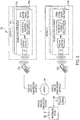
FIG. 5 depicts an operating environment for the system ofFIG. 1 according to one embodiment. - A detailed description of one or more embodiments of the disclosed apparatus and method are presented herein by way of exemplification and not limitation with reference to the Figures.
- The term "about" is intended to include the degree of error associated with measurement of the particular quantity based upon the equipment available at the time of filing the application. For example, "about" can include a range of ± 8% or 5%, or 2% of a given value.
- The terminology used herein is for the purpose of describing particular embodiments only and is not intended to be limiting of the present disclosure. As used herein, the singular forms "a", "an" and "the" are intended to include the plural forms as well, unless the context clearly indicates otherwise. It will be further understood that the terms "comprises" and/or "comprising," when used in this specification, specify the presence of stated features, integers, steps, operations, elements, and/or components, but do not preclude the presence or addition of one or more other features, integers, steps, operations, element components, and/or groups thereof.
- Aircraft maintenance includes collecting health and operational information from various aircraft systems, subsystems, and/or sensors. Collecting health and maintenance data associated with systems and/or sensors currently requires physical access ports in the avionics systems. These ports may be compromised by environmental conditions and other operational factors. Aircraft security may also be compromised at the physical port access points. Collecting prognostic and diagnostic data from multiple sensors, ports, and controllers can also be time consuming, and the collected health data can be analyzed only in the office environment.
-
FIG. 1 will be described in conjunction withFIG. 5 depicting anoperating environment 500 forsystem 100.FIG. 1 depicts asystem 100 for RFID based prognostic and diagnostic data communication for an aircraft, according to one embodiment. The architecture shown inFIG. 1 illustrates one aspect of an interconnection of a RFID reader 102 (hereafter "RFID reader 102") and a passive RFID tag 202 (hereafter "tag 202").RFID reader 102 connects with the existing avionics systems and/or sensors of an aircraft (such as, for example, anice detector 104a and awindshield wiper system 104n via wireless RFID communication.RFID reader 102 is configured to be portable or mobile such that a user may carry the reader in a single hand. Further, in one embodiment, the RFID reader can write configuration data (e.g., installation date, aircraft tail no., manufacturer, etc.) into the tag memory of the RFID tag. - Referring briefly to
FIG. 5 , anoperating environment 500 forsystem 100 is shown, according to embodiments. In one aspect, one ormore RFID readers 102a ... 102n (where reference toRFID reader 102 may be any one ofRFID readers 102a...102n) interface with one or more of avionics systems and/orsensors 104a ... 104n ofaircrafts 508a to 508nRFID reader 102 is configured to retrieve prognostic and diagnostic health data from one or more avionics systems/sensors 104a .. 104n using RFID via one or more passive RFID tags integrated into the systems or sensors. In some aspects described hereafter,RFID reader 102 receives and stores health and maintenance data indicative of the health or operation of the avionics system in non-volatile memory on the reader, and synchronizes the health and maintenance data retrieved from multiple avionics systems on one or more aircrafts (e.g.,aircrafts 508a ... 508n) with amaintenance server 502 via acommunication network 504.Maintenance server 502 stores the health and maintenance data in one ormore databases 506 and can be implemented as a single server or one or more servers. - According to one embodiment,
RFID reader 102 may connect withmultiple avionics systems 104a...104n (collectively systems 104) simultaneously or independently.Systems 104 are considered to be on a single aircraft. In some aspects,RFID reader 102 may connect to multiple avionics of each aircraft, and may also connect to multiple aircraft when proximate to RFID tags on the aircraft. Proximate to may be, for example, within 1-40 feet of any particular RFID tag. In other aspects, the distance may be extended with higher powered transmitters (and batteries) on theRFID reader 102. - The health and maintenance data is collected from the avionics systems/sensors of
aircrafts 508a ... 508n. Any actions taken by a user of the RFID reader 102 (responsive to data that indicates a maintenance problem) are archived byRFID reader 102 inmaintenance database 506 and/orserver 502 for audit purposes and for future analysis. In one embodiment, theRFID reader 102 enables the user to take immediate actions by looking into the health data. -
RFID reader 102 automatically establishes a secured connection viacommunication network 504 with themaintenance server 502. In some aspects, the connection tomaintenance server 502 is manually established by the technician. The secured connection to the maintenance server is established through the wired and/or wireless communication interface available in the RFID reader. - Data stored in multiple RFID readers (e.g., 102a...102n) are synchronized to the maintenance server via the secured and dedicated LAN/WAN network. The data are encrypted using an encryption algorithm before synchronizing to the maintenance server to avoid any security related issues/vulnerabilities. In one embodiment, the diagnostics health data are synchronized to
server 502 for taking immediate correction actions and/or for recording the actions already taken. Similarly, the prognostic health data may be synchronized to airlines or OEM's maintenance servers for planning preventative maintenance. - Referring again to
FIG. 1 ,RFID reader 102 includes anantenna 114 operatively connectable to one or more avionics systems and/or sensors (104a ... 104n), acommunication interface 108 connected to aprocessor 109 for interacting with information received from avionics systems and/orsensors 104a ... 104n), agraphic user interface 110, and amemory 112. In one embodiment,RFID reader 102 is configured to broadcast or produce electromagnetic (RF)energy 116 viaantenna 114 to the RFID tag in any of the avionics systems or sensors (e.g., ice detector 104).Graphical user interface 110 is configured to receive a user selection indicative of an avionics system and/or sensor to retrieve the health and maintenance data, to view any anomalies, to receive user input indicative of one or more actions, and to receive one or more instructions to record the action taken. -
Reader memory 112 is a non-volatile internal memory configured to store the retrieved prognostic and diagnostic health data from avionics systems and/orsensors 104a ... 104n, The capacity of reader-memory 112 is configured to hold large portions (e.g., gigabytes) of data. The stored data may be, for example, 10 GB, 20 GB, etc.Memory 112 stores health and maintenance data from multiple avionics systems/sensors (e.g., 104a ... 104n) and from multiple aircrafts (e.g.,aircrafts 508a ...508n as described hereafter with respect toFIG. 5 ). -
Communication interface 108 is a wired and/or wireless communication interface configured for synchronizing the retrieved health and maintenance data to a maintenance server (e.g.,maintenance server 502 as shown inFIG. 5 ). -
FIG. 2 illustrates an avionics system/sensor 104 (hereafter system 104) configured for interfacing withRFID reader 102, according to one embodiment. During the normal operation of the aircraft, for example when the aircraft power is available to micro-controller unit (MCU) 206,MCU 206 performs the Prognostic and Diagnostic Health Monitor (PDHM) operations and stores the health and maintenance data on the RFID tag-memory 204 of theRFID tag 202. Storing the PDHM data directly onRFID tag memory 204 of theRFID tag 202 eliminates the addition of external memory chips to store the health and maintenance data for PDHM operations.MCU 206 and tag-memory 204 are connected via acommunication interface bus 212. -
System 104 includes a passive Ultra High Frequency (UHF)RFID tag 202, anantenna 214 configured to receiveRF energy 116 fromRFID reader 102 and to transmit health and maintenance data to the RFID reader.System 104 includes non-volatile memory (e.g., tag-memory 204) configured to store tag information, configuration information, health data, maintenance data etc.System 104 includes acommunication interface bus 212 for data connectivity betweenRFID tag 202 and theMCU 206.System 104 is operatively connected to receive, control, monitor, etc. one or moreother functions 210 of the aircraft. -
FIG. 3 illustrates astructure 300 for organization of health and maintenance data in the tag-memory 204, according to one embodiment. A standardized message format may be used for health and maintenance data, which enables easy integration of thepassive RFID tag 202 withMCU 206.Structure 300 may be used to store health and maintenance data in the tag-memory 204.Structure 300 can include (but is not limited to) a RFID tag identifier (ID) 302, System/Sensor configuration data 304,maintenance data 306,Prognostic health data 308, anddiagnostic health data 310. The data ofstructure 300 are stored in tag-memory 204.Prognostic health data 308 anddiagnostic health data 310 include various hardware health parameters (1, 2, ... n) value with control limits and error information. An example of a hardware health parameter may be, for example, hardware life, voltage, current, wear, etc. -
FIGS. 4a-4f depict various screens of exemplary graphic user interface (GUI) 110 ofRFID reader 102, according to one embodiment. As shown inFIG. 4a ,GUI 110 includes a plurality ofsystems 402 of an aircraft.Systems 402 are discovered by reading RFID tags in each of the systems withRFID reader 102.Additional systems 404 may populateGUI 110 as those systems become readable byRFID reader 102.GUI 110 may also include a user-selectable synchronize toserver input 406. Accordingly, a user may selectinput element 406 and causeRFID reader 102 to synchronize the stored data with one ormore servers 502. -
FIG. 4b showsGUI 110 having user-selectable inputs for reading data from avionics systems/sensors 104.Inputs 408 are configured for manually reading data, writing data, and resetting data stored onmemory 204. -
FIG. 4c depicts examples ofprognostic health data 308 anddiagnostic health data 310. According to one embodiment,RFID reader 102 displays information respective to each of the scanned readsystems 402. Prognostic data may show one or more errors (e.g., shaft error 412), and may show one or more functionality confirmations (e.g.,motor OK 414, gears OK 416, and blade OK 418, etc.). Details of an error (e.g. Shaft error 412) and/or confirmations (e.g. Blade OK 418) are output byprocessor 109 after receiving user input as a selected element (e.g. 420 or 440). -
FIG. 4d depictsGUI 110 having details for one of the error and/or confirmations ofFIG. 4c . After receiving a user-selected input (selectedelement FIG. 4c ,RFID reader 102 is configured to provide details as shown inFIG. 4d .Maintenance data 306 may be output byRFID reader 102 including any details regarding the error and/ or confirmations. -
FIG. 4e shows an example of configuration data or operation data onGUI 110. In some aspects, a particular element of an avionics system/sensor (e.g.,windshield wiper system 104n) may include various operational limits 424 and max and min recordedvalues processor 109 with a user-readable warning oralert 434. Error details 436 may be displayed byprocessor 109 having various details regarding the alert at issue.Selection element 437 may receive userinput directing processor 109 to document any actions taken respective to the warning oralert 434. -
FIG. 4f depicts details of various actions taken 442 in connection with warning oralert 434.Individual actions 438 may be manually input by the user in some aspects. A submitbutton 444 may be provide to store the data to a memory such asmemory 112 ofRFID reader 102. - While the present disclosure has been described with reference to an exemplary embodiment or embodiments, it will be understood by those skilled in the art that various changes may be made and equivalents may be substituted for elements thereof without departing from the scope of the present disclosure. In addition, many modifications may be made to adapt a particular situation or material to the teachings of the present disclosure without departing from the essential scope thereof. Therefore, it is intended that the present disclosure not be limited to the particular embodiment disclosed as the best mode contemplated for carrying out this present disclosure, but that the present disclosure will include all embodiments falling within the scope of the claims.
Claims (15)
- A method of radio frequency identification (RFID) communication between an avionics system and an RFID reader (102) comprising:connecting to a wireless RFID tag in the avionics system with the RFID reader (102) while proximate to but not touching the RFID tag;receiving, via wireless communication from the RFID tag, system data at the RFID reader comprising one or more of prognostic data and diagnostic health data associated with the avionics system;displaying, on a graphic user interface (110), the system data such that the system data is user-selectable for identification of one or more avionics system errors; andsynchronizing, via a communications interface (108) on the RFID reader, the system data with one or more maintenance servers;writing, via wireless communication to the RFID tag, the configuration data.
- The method of claim 1, wherein the RFID reader (102) is configured for connecting to a plurality of RFID tags in a plurality of avionics systems within a single aircraft and wherein the RFID tags can operate without power from the aircraft.
- The method of claim 2, wherein the RFID reader (102) is configured for connecting to the plurality of RFID tags in the plurality of avionics systems simultaneously.
- The method of any preceding claim, wherein the system data is identifiable by the RFID reader (102) as unique to a particular system or sensor in a particular aircraft.
- The method of any preceding claim, wherein the RFID reader (102) is configured for:receiving the system data at the RFID reader (102);displaying the system data on the user interface (110);receiving a user selection of a portion of the system data indicative of the one or more avionics system;and outputting secondary information indicative of one or more aspects of the one or more avionics system responsive to the received user selection, wherein the secondary information includes one or more of configuration data, maintenance data, prognostic health data, and diagnostic health data.
- The method of claim 5, wherein the RFID reader (102) is configured for receiving the user selection of the portion of the system data indicative of the one or more avionics system errors; and
receiving a user input indicative of one or more actions taken responsive to the one or more avionics system errors. - The method of any preceding claim, wherein prognostic data comprises an indication of operability of a respective avionics system hardware component, wherein the indication of operability indicates whether the respective avionics system hardware component is functioning normally or abnormally.
- The method of any preceding claim, wherein the diagnostic data comprises an indication of a predetermined characteristic of a respective avionics system hardware component, the predetermined characteristic indicating when a hardware component of the avionics system is functioning normally or abnormally.
- The method of any preceding claim, wherein the maintenance server is configured to receive system data from a plurality of RFID readers in associated with a plurality of aircraft.
- A system for radio frequency identification (RFID) data communication between an avionics system and a RFID reader (102) comprising:RFID reader (102) having a processor configured to:connect to a wireless RFID tag in the avionics system with the RFID reader (102) while proximate to but not touching the RFID tag;receive, via wireless communication from the RFID tag, system data at the RFID reader comprising one or more of prognostic data and diagnostic health data associated with the avionics system;display, on a graphic user interface (110), the system data such that the system data is user-selectable for identification of one or more avionics system errors; andsynchronize, via a communications interface (108) on the RFID reader, the system data with one or more maintenance servers;write, via wireless communication to the RFID tag, the configuration data.
- The system of claim 10, wherein the RFID reader (102) is configured for connecting to a plurality of RFID tags in a plurality of avionics systems within a single aircraft and wherein the RFID tags can operate without power from the aircraft.
- The system of claim 11, wherein the RFID reader (102) is configured for connecting to the plurality of RFID tags in the plurality of avionics systems simultaneously.
- The system of any of claims 10-12, wherein the system data is identifiable by the RFID reader as unique to a particular system or sensor in a particular aircraft.
- The system of any of claims 10-13, wherein the RFID reader (102) is configured for:receiving the system data;displaying the system data on the user interface;receiving a user selection of a portion of the system data indicative of the one or more avionics system; andoutputting secondary information indicative of one or more aspects of the one or more avionics system responsive to the received user selection, wherein the secondary information includes one or more of configuration data, maintenance data, prognostic health data, and diagnostic health data.
- The system of claim 14, wherein the RFID reader (102) is configured for receiving the user selection of the portion of the system data indicative of the one or more avionics system errors; and
receiving a user input indicative of one or more actions taken responsive to the one or more avionics system errors.
Applications Claiming Priority (1)
| Application Number | Priority Date | Filing Date | Title |
|---|---|---|---|
| IN201711018751 | 2017-05-29 |
Publications (1)
| Publication Number | Publication Date |
|---|---|
| EP3410407A1 true EP3410407A1 (en) | 2018-12-05 |
Family
ID=62486440
Family Applications (1)
| Application Number | Title | Priority Date | Filing Date |
|---|---|---|---|
| EP18174789.0A Withdrawn EP3410407A1 (en) | 2017-05-29 | 2018-05-29 | Rfid based prognostic and diagnostic data communication |
Country Status (2)
| Country | Link |
|---|---|
| US (1) | US20180341794A1 (en) |
| EP (1) | EP3410407A1 (en) |
Cited By (2)
| Publication number | Priority date | Publication date | Assignee | Title |
|---|---|---|---|---|
| EP3961503A1 (en) * | 2020-08-26 | 2022-03-02 | Cattron North America, Inc. | Radio-frequency identification (rfid) systems and methods for changing operator control unit (ocu) configurations |
| EP4011785A1 (en) * | 2020-12-11 | 2022-06-15 | B/E Aerospace, Inc. | Aircraft systems with built in tests |
Families Citing this family (6)
| Publication number | Priority date | Publication date | Assignee | Title |
|---|---|---|---|---|
| US10839622B2 (en) * | 2018-03-27 | 2020-11-17 | The Boeing Company | Aircraft maintenance condition detection |
| EP3734377A1 (en) * | 2019-05-02 | 2020-11-04 | ABB Schweiz AG | Method for configuring automation apparatus, automation apparatus, and reader apparatus |
| US11661211B2 (en) * | 2019-12-06 | 2023-05-30 | The Boeing Company | Systems and methods for processor module failure assessment |
| US11414216B2 (en) * | 2019-12-13 | 2022-08-16 | Rosemount Aerospace Inc. | Monitoring aircraft windscreen blade usage and health |
| US12243358B2 (en) | 2021-10-18 | 2025-03-04 | General Electric Company | Methods, apparatuses, and storage media to track engine components |
| US20250361024A1 (en) * | 2024-05-23 | 2025-11-27 | Rosemount Aerospace Inc. | PROGNOSTIC HEALTH MONITOR FOR AIRCRAFT-BASED ANALOG ANGLE OF ATTACK (AoA) SENSORS |
Citations (3)
| Publication number | Priority date | Publication date | Assignee | Title |
|---|---|---|---|---|
| US20060155430A1 (en) * | 2005-01-11 | 2006-07-13 | Burgess Patrick E | RFID vehicle management system and method |
| US20120150380A1 (en) * | 2007-07-03 | 2012-06-14 | The Boeing Company | Condition-based maintenance systems and methods |
| US20160196457A1 (en) * | 2015-01-06 | 2016-07-07 | Honeywell International Inc. | Line replaceable unit health nodes and methods for determining maintenance actions relating to line replaceable units |
Family Cites Families (17)
| Publication number | Priority date | Publication date | Assignee | Title |
|---|---|---|---|---|
| US7557696B2 (en) * | 2001-09-11 | 2009-07-07 | Zonar Systems, Inc. | System and process to record inspection compliance data |
| US8400296B2 (en) * | 2001-09-11 | 2013-03-19 | Zonar Systems, Inc. | Method and apparatus to automate data collection during a mandatory inspection |
| US9117128B2 (en) * | 2005-12-09 | 2015-08-25 | Tego, Inc. | External access to memory on an RFID tag |
| US7545274B2 (en) * | 2006-04-10 | 2009-06-09 | The Boeing Company | RFID data management system |
| GB0704878D0 (en) * | 2007-03-14 | 2007-04-18 | Trw Ltd | Aircraft landing gear monitoring apparatus |
| US8130081B2 (en) * | 2008-02-21 | 2012-03-06 | The Boeing Company | Data management for intermittently connected sensors |
| US8461965B2 (en) * | 2010-01-13 | 2013-06-11 | The Boeing Company | Portable radio frequency identification (RFID) reader |
| US8963720B2 (en) * | 2010-05-11 | 2015-02-24 | The Boeing Company | RFID tag container |
| US9113234B2 (en) * | 2010-07-27 | 2015-08-18 | The Boeing Company | Wireless device association system |
| US9162776B2 (en) * | 2010-08-18 | 2015-10-20 | The Boeing Company | Aircraft safety and configuration monitoring system and method |
| US8981967B1 (en) * | 2010-08-18 | 2015-03-17 | The Boeing Company | Aircraft equipment management system |
| US8823554B2 (en) * | 2010-12-09 | 2014-09-02 | The Boeing Company | Managing a plurality of radio frequency identification devices |
| US8791823B2 (en) * | 2011-06-03 | 2014-07-29 | The Boeing Company | Aircraft part control system |
| US8958945B2 (en) * | 2012-02-07 | 2015-02-17 | Ge Aviation Systems Llc | System and methods for maintaining and operating an aircraft |
| US9058703B2 (en) * | 2012-03-14 | 2015-06-16 | Flextronics Ap, Llc | Shared navigational information between vehicles |
| US8989951B1 (en) * | 2012-10-30 | 2015-03-24 | The Boeing Company | Maintaining the airworthiness configuration of aircraft |
| US9740554B2 (en) * | 2015-06-12 | 2017-08-22 | The Boeing Company | Methods and systems for prioritizing replacement of at least one part for vehicle fault analysis |
-
2017
- 2017-08-04 US US15/669,148 patent/US20180341794A1/en not_active Abandoned
-
2018
- 2018-05-29 EP EP18174789.0A patent/EP3410407A1/en not_active Withdrawn
Patent Citations (3)
| Publication number | Priority date | Publication date | Assignee | Title |
|---|---|---|---|---|
| US20060155430A1 (en) * | 2005-01-11 | 2006-07-13 | Burgess Patrick E | RFID vehicle management system and method |
| US20120150380A1 (en) * | 2007-07-03 | 2012-06-14 | The Boeing Company | Condition-based maintenance systems and methods |
| US20160196457A1 (en) * | 2015-01-06 | 2016-07-07 | Honeywell International Inc. | Line replaceable unit health nodes and methods for determining maintenance actions relating to line replaceable units |
Cited By (4)
| Publication number | Priority date | Publication date | Assignee | Title |
|---|---|---|---|---|
| EP3961503A1 (en) * | 2020-08-26 | 2022-03-02 | Cattron North America, Inc. | Radio-frequency identification (rfid) systems and methods for changing operator control unit (ocu) configurations |
| US11645482B2 (en) | 2020-08-26 | 2023-05-09 | Cattron North America, Inc. | Radio-frequency identification (RFID) systems and methods for changing operator control unit (OCU) configurations |
| EP4011785A1 (en) * | 2020-12-11 | 2022-06-15 | B/E Aerospace, Inc. | Aircraft systems with built in tests |
| US11451462B2 (en) | 2020-12-11 | 2022-09-20 | B/E Aerospace, Inc. | Aircraft systems with built in tests |
Also Published As
| Publication number | Publication date |
|---|---|
| US20180341794A1 (en) | 2018-11-29 |
Similar Documents
| Publication | Publication Date | Title |
|---|---|---|
| US20180341794A1 (en) | Rfid based prognostic and diagnostic data communication | |
| US20150310723A1 (en) | Trending machine health data using rfid transponders | |
| US9489340B2 (en) | Electrical power health monitoring system | |
| US9507982B2 (en) | Line replaceable unit health nodes and methods for determining maintenance actions relating to line replaceable units | |
| EP3065016B1 (en) | Aircraft lru data collection and reliability prediction | |
| US8599044B2 (en) | System and method to assess and report a health of a tire | |
| US10650614B2 (en) | Aircraft maintenance event prediction using higher-level and lower-level system information | |
| US8682508B2 (en) | Methods of identifying flight profiles in aircraft maintenance operations | |
| US20140028462A1 (en) | Reconfigurable equipment monitoring systems and methods | |
| US20130335197A1 (en) | Electronic system comprising of a plurality of electronic equipment units, electronic equipment for such a system and method for management and maintenance of such a system | |
| CN103246692A (en) | System and methods for maintaining and operating an aircraft | |
| AU2020395182B2 (en) | Operational condition monitoring system | |
| CN103105845B (en) | Apparatus and method for aggregating health management information | |
| WO2013131080A2 (en) | Master antenna controller application and device | |
| CN110901948A (en) | System for collecting and analyzing data relating to an aircraft | |
| US8989951B1 (en) | Maintaining the airworthiness configuration of aircraft | |
| CN103927793A (en) | Patrol system | |
| US11803723B2 (en) | Electronic display tags for tracking election equipment | |
| CN113632148A (en) | System for providing operational data | |
| TWM540315U (en) | Process parameter monitoring system | |
| JP6875850B2 (en) | Field data collection system | |
| US10853594B2 (en) | Lockout tagout system and method | |
| US9070030B2 (en) | Management system for container data center | |
| CN109870834B (en) | Liquid crystal glass power-up detection system | |
| EP4224457A1 (en) | Aircraft communication visualization |
Legal Events
| Date | Code | Title | Description |
|---|---|---|---|
| PUAI | Public reference made under article 153(3) epc to a published international application that has entered the european phase |
Free format text: ORIGINAL CODE: 0009012 |
|
| STAA | Information on the status of an ep patent application or granted ep patent |
Free format text: STATUS: THE APPLICATION HAS BEEN PUBLISHED |
|
| AK | Designated contracting states |
Kind code of ref document: A1 Designated state(s): AL AT BE BG CH CY CZ DE DK EE ES FI FR GB GR HR HU IE IS IT LI LT LU LV MC MK MT NL NO PL PT RO RS SE SI SK SM TR |
|
| AX | Request for extension of the european patent |
Extension state: BA ME |
|
| STAA | Information on the status of an ep patent application or granted ep patent |
Free format text: STATUS: REQUEST FOR EXAMINATION WAS MADE |
|
| 17P | Request for examination filed |
Effective date: 20190605 |
|
| RBV | Designated contracting states (corrected) |
Designated state(s): AL AT BE BG CH CY CZ DE DK EE ES FI FR GB GR HR HU IE IS IT LI LT LU LV MC MK MT NL NO PL PT RO RS SE SI SK SM TR |
|
| STAA | Information on the status of an ep patent application or granted ep patent |
Free format text: STATUS: EXAMINATION IS IN PROGRESS |
|
| 17Q | First examination report despatched |
Effective date: 20201210 |
|
| STAA | Information on the status of an ep patent application or granted ep patent |
Free format text: STATUS: THE APPLICATION HAS BEEN WITHDRAWN |
|
| 18W | Application withdrawn |
Effective date: 20210211 |