EP3410389A1 - Image processing method and device - Google Patents
Image processing method and device Download PDFInfo
- Publication number
- EP3410389A1 EP3410389A1 EP17743592.2A EP17743592A EP3410389A1 EP 3410389 A1 EP3410389 A1 EP 3410389A1 EP 17743592 A EP17743592 A EP 17743592A EP 3410389 A1 EP3410389 A1 EP 3410389A1
- Authority
- EP
- European Patent Office
- Prior art keywords
- image
- sub
- images
- target
- sample
- Prior art date
- Legal status (The legal status is an assumption and is not a legal conclusion. Google has not performed a legal analysis and makes no representation as to the accuracy of the status listed.)
- Ceased
Links
Images


Classifications
-
- G—PHYSICS
- G06—COMPUTING OR CALCULATING; COUNTING
- G06T—IMAGE DATA PROCESSING OR GENERATION, IN GENERAL
- G06T3/00—Geometric image transformations in the plane of the image
- G06T3/40—Scaling of whole images or parts thereof, e.g. expanding or contracting
-
- G—PHYSICS
- G06—COMPUTING OR CALCULATING; COUNTING
- G06T—IMAGE DATA PROCESSING OR GENERATION, IN GENERAL
- G06T3/00—Geometric image transformations in the plane of the image
- G06T3/40—Scaling of whole images or parts thereof, e.g. expanding or contracting
- G06T3/4038—Image mosaicing, e.g. composing plane images from plane sub-images
-
- G—PHYSICS
- G06—COMPUTING OR CALCULATING; COUNTING
- G06F—ELECTRIC DIGITAL DATA PROCESSING
- G06F18/00—Pattern recognition
- G06F18/20—Analysing
- G06F18/25—Fusion techniques
- G06F18/253—Fusion techniques of extracted features
-
- G—PHYSICS
- G06—COMPUTING OR CALCULATING; COUNTING
- G06F—ELECTRIC DIGITAL DATA PROCESSING
- G06F17/00—Digital computing or data processing equipment or methods, specially adapted for specific functions
- G06F17/10—Complex mathematical operations
- G06F17/16—Matrix or vector computation, e.g. matrix-matrix or matrix-vector multiplication, matrix factorization
-
- G—PHYSICS
- G06—COMPUTING OR CALCULATING; COUNTING
- G06F—ELECTRIC DIGITAL DATA PROCESSING
- G06F18/00—Pattern recognition
- G06F18/20—Analysing
- G06F18/23—Clustering techniques
-
- G—PHYSICS
- G06—COMPUTING OR CALCULATING; COUNTING
- G06T—IMAGE DATA PROCESSING OR GENERATION, IN GENERAL
- G06T5/00—Image enhancement or restoration
- G06T5/50—Image enhancement or restoration using two or more images, e.g. averaging or subtraction
-
- G—PHYSICS
- G06—COMPUTING OR CALCULATING; COUNTING
- G06T—IMAGE DATA PROCESSING OR GENERATION, IN GENERAL
- G06T7/00—Image analysis
- G06T7/10—Segmentation; Edge detection
-
- G—PHYSICS
- G06—COMPUTING OR CALCULATING; COUNTING
- G06T—IMAGE DATA PROCESSING OR GENERATION, IN GENERAL
- G06T7/00—Image analysis
- G06T7/10—Segmentation; Edge detection
- G06T7/174—Segmentation; Edge detection involving the use of two or more images
Definitions
- the present application relates to the field of image processing technologies, and in particular, to image processing methods and devices.
- image recognitions such as face recognition and certificate image recognition are used in more and more network services.
- many images are marked by reticulated patterns and watermarks.
- image recognition efficiency reduces and image recognition difficulty increases.
- a main object of the present application is to provide image processing methods and devices.
- An image processing method includes: removing an interference factor from an original image by using a plurality of methods, to obtain a plurality of sample images; segmenting each sample image into a plurality of sample sub-images based on a predetermined segmentation rule; determining a target sub-image from sample sub-images that have the same attributes; and combining a plurality of target sub-images with different attributes into a target image.
- the determining a target sub-image from sample sub-images that have the same attributes includes: determining a mathematical parameter of each sample sub-image; dividing the sample sub-images that have the same attributes into a plurality of image sets based on the mathematical parameters by using a clustering algorithm, where each image set includes one or more sample sub-images; and determining the target sub-image from an image set that includes the maximum number of sample sub-images.
- the determining a mathematical parameter of each sample sub-image includes: generating an RGB vector for the sample sub-image based on RGB information of each pixel in the sample sub-image to use the RGB vector as the mathematical parameter of the sample sub-image.
- the determining the target sub-image from an image set that includes the maximum number of sample sub-images includes: determining, as the target sub-image from the image set that includes the maximum number of sample sub-images, a sample sub-image that corresponds to the center point in the image set obtained after clustering.
- the combining a plurality of target sub-images with different attributes into a target image includes: combining the plurality of target sub-images with different attributes into the target image based on location coordinates of each pixel in the target sub-image.
- An image processing device includes: an interference removing unit, configured to remove an interference factor from an original image by using a plurality of methods, to obtain a plurality of sample images; an image segmentation unit, configured to segment each sample image into a plurality of sample sub-images based on a predetermined segmentation rule; a target determining unit, configured to determine a target sub-image from sample sub-images that have the same attributes; and a target combination unit, configured to combine a plurality of target sub-images with different attributes into a target image.
- the target determining unit includes: a parameter determining subunit, configured to determine a mathematical parameter of each sample sub-image; a set division subunit, configured to divide the sample sub-images that have the same attributes into a plurality of image sets based on the mathematical parameters by using a clustering algorithm, where each image set includes one or more sample sub-images; and a target determining subunit, configured to determine the target sub-image from an image set that includes the maximum number of sample sub-images.
- the parameter determining subunit is configured to generate an RGB vector for the sample sub-image based on RGB information of each pixel in the sample sub-image to use the RGB vector as the mathematical parameter of the sample sub-image.
- the target determining subunit is configured to determine, as the target sub-image from the image set that includes the maximum number of sample sub-images, a sample sub-image that corresponds to the center point in the image set obtained after clustering.
- the target combination unit is configured to combine the plurality of target sub-images with different attributes into the target image based on location coordinates of each pixel in the target sub-image.
- the interference factor in the original image can be removed first by using the plurality of methods, to obtain a plurality of sample images.
- Each of the plurality of sample images can then be segmented into a plurality of sample sub-images based on the predetermined segmentation rule.
- the target sub-image can then be determined from the sample sub-images that have the same attributes, so that a target sub-image most similar to a real image can be determined from the plurality of sample sub-images that have the same attributes.
- the plurality of target sub-images with different attributes can then be combined into the target image.
- the obtained target image can restore the real image with high precision to improve accuracy of subsequent image recognition.
- first, second, third, etc. can be used in the present application to describe various types of information, the information is not limited by the terms. These terms are merely used to differentiate information of the same type. For example, without departing from the scope of the present application, first information may be referred to as second information, and similarly the second information may also be referred to as the first information. Depending on the context, for example, the word “if' used here may be explained as “while”, “when”, or "in response to determining”.
- image processing algorithms or image processing tools such as Photoshop can be used to remove reticulated patterns or watermarks in an original image.
- image processing algorithms or image processing tools such as Photoshop can be used to remove reticulated patterns or watermarks in an original image.
- an image obtained by removing the reticulated pattern or the watermark usually cannot restore the real image of the original image.
- image recognition accuracy may be affected.
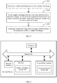
- FIG. 1 is a schematic flowchart illustrating an image processing method, according to an example implementation of the present application.
- the image processing method can be applied to a terminal device.
- the terminal device can include an intelligent device such as a smartphone, a tablet computer, a personal digital assistant (PDA), and a PC.
- PDA personal digital assistant
- the image processing method can also be applied to a server, which is not limited in the present application.
- the image processing method can include the following steps.
- Step 101 Remove an interference factor from an original image by using a plurality of methods, to obtain a plurality of sample images.
- the original image is usually an image to be recognized.
- the original image may include one or more interference factors.
- the interference factor is usually an interference pattern such as a reticulated pattern or a watermark added to the real image.
- the interference factor in the original image can be removed by using different interference factor removing methods provided in the related technology to obtain the plurality of sample images.
- the interference factor in the original image can be removed by using image processing software such as Photoshop.
- Step 102 Segment each sample image into a plurality of sample sub-images based on a predetermined segmentation rule.
- each sample image can be segmented into a plurality of sub-images based on the predetermined segmentation rule.
- the sub-image obtained after the segmentation can be referred to as a sample sub-image.
- the predetermined segmentation rule can be set by a developer.
- the unit used for segmenting can be the size of the sample sub-image, or a number of sample sub-images, which is not limited in the present application.
- the predetermined segmentation rule can be segmenting a sample image into 25 sample sub-images, such as segmenting the sample image into 25 sample sub-images based on a 5x5 rule.
- N sample images can be obtained if the interference factor in the original image is removed by using N different methods in step 101. Further, a total of NxM sample sub-images can be obtained if each sample image is segmented into M sample sub-images. M and N are natural numbers greater than 1.
- Step 103 Determine a target sub-image from sample sub-images that have the same attributes.
- each sample sub-image includes a corresponding attribute.
- the attribute can be used to indicate location information of the sample sub-image in a sample image that includes the sample sub-image.
- image A is a sample image obtained by removing interference in the original image.
- the sample image can be segmented into 3x3 sample sub-images based on the predetermined segmentation rule. Attributes of the nine sample sub-images are respectively A11, A12, A13, A21, ..., and A33.
- the segmentation rule shown in FIG. 2 is used as an example.
- a total of Nx9 sample sub-images can be obtained if the interference factor in the original image is removed by using N different methods to obtain N sample images.
- a target sub-image with attribute A11 can be determined from the N sample sub-images with attributes A11
- a target sub-image with attribute A12 can be determined from the N sample sub-images with attribute A12
- nine target sub-images with attributes A11 to A33 can be similarly determined.
- Step 104 Combine a plurality of target sub-images with different attributes into a target image.
- the plurality of target sub-images with different attributes can be combined into the target image.
- the plurality of target sub-images can be combined into the target image based on the attribute of each target sub-image, or the plurality of target sub-images can be combined into the target image based on location coordinates of each pixel in each target sub-image, which is not limited in the present application.
- the segmentation rule shown in FIG. 2 is used as an example.
- the nine target sub-images with attributes A11 to A33 can be combined into one target image.
- the interference factor in the original image can be removed first by using the plurality of methods, to obtain a plurality of sample images.
- Each of the plurality of sample images can then be segmented into the plurality of sample sub-images based on the predetermined segmentation rule.
- the target sub-image can then be determined from the sample sub-images that have the same attributes, so that a target sub-image most similar to the real image can be determined from the plurality of sample sub-images that have the same attributes.
- the plurality of target sub-images with different attributes can then be combined into the target image.
- the obtained target image can restore the real image with high precision to improve accuracy of subsequent image recognition.
- a process of determining a target sub-image from sample sub-images that have the same attributes can include the following steps.
- Step 301 Determine a mathematical parameter of each sample sub-image.
- the mathematical parameter of each sample sub-image can be determined for subsequent calculations.
- an RGB vector can be generated for the sample sub-image based on RGB information of each pixel in the sample sub-image to use the RGB vector as the mathematical parameter of the sample sub-image.
- the RGB information such as an RGB value of each pixel in the sample sub-image can be obtained first.
- the RGB vector can be generated based on the RGB information of each pixel.
- the RGB vector of the sample sub-image can be ⁇ R 1 , R 2 ,..., R E ⁇ if the sample sub-image includes K pixels, where an RGB value of the ith pixel is R 1 , and a value of i is 1 to K.
- Step 302 Divide the sample sub-images that have the same attributes into a plurality of image sets based on the mathematical parameters by using a clustering algorithm, where each image set includes one or more sample sub-images.
- the plurality of sample sub-images that have the same attributes can be divided into the plurality of image sets based on the mathematical parameters of the sample sub-images by using the clustering algorithm.
- the clustering algorithm can include a Density-Based Spatial Clustering of Applications with Noise (DBSCAN) clustering algorithm, a K-means clustering algorithm, etc., which are not limited in the present application.
- DBSCAN Density-Based Spatial Clustering of Applications with Noise
- a scanning radius (eps) and the minimum number of points (minPts) can be predetermined when the DBSCAN clustering algorithm is used.
- Each sample sub-image corresponds to one point in a clustering process.
- the minimum number of points is the minimum number of sample sub-images that can be included in an image set obtained after the division.
- related calculation can be performed based on the mathematical parameter of the sample sub-image. For example, a distance between RGB vectors of two sample sub-images can be used as a distance between the two sample sub-images.
- Step 303 Determine the target sub-image from an image set that includes the maximum number of sample sub-images.
- step 302 after the sample sub-images that have the same attributes are divided into the plurality of image sets, the number of sample sub-images included in each image set is determined, and then the target sub-image can be determined from the image set that includes the maximum number of sample sub-images.
- a sample sub-image that corresponds to the center point in the image set obtained after clustering can be determined as the target sub-image from the image set that includes the maximum number of sample sub-images.
- the clustering algorithm can be used to determine the target sub-image from the sample sub-images that have the same attributes, to ensure that the determined target sub-image is more similar to a real image.
- the present application further provides an implementation of an image processing device.
- the implementation of the image processing device in the present application can be applied to a terminal device or a server.
- the device implementation can be implemented by using software, hardware, or both.
- Software implementation is used as an example.
- the device is formed by reading a corresponding computer program instruction in a non-volatile memory into the memory by a processor of the terminal device or the server where the device is located.
- FIG. 4 is a structural diagram illustrating hardware of a terminal device or a server where an image processing device in the present application is located.
- the terminal device or the server where the device in the present implementation is located can usually include other hardware based on actual functions of the terminal device or the server. Details are not repeated here.
- FIG. 5 is a schematic structural diagram illustrating an image processing device, according to an example implementation of the present application.
- the image processing device 400 can be applied to the terminal device or the server shown in FIG. 4 , and includes an interference removing unit 401, an image segmentation unit 402, a target determining unit 403, and a target combination unit 404.
- the target determining unit 403 can further include a parameter determining subunit 4031, a set division subunit 4032, and a target determining subunit 4033.
- the interference removing unit 401 is configured to remove an interference factor from an original image by using a plurality of methods, to obtain a plurality of sample images.
- the image segmentation unit 402 is configured to segment each sample image into a plurality of sample sub-images based on a predetermined segmentation rule.
- the target determining unit 403 is configured to determine a target sub-image from sample sub-images that have the same attributes.
- the target combination unit 404 is configured to combine a plurality of target sub-images with different attributes into a target image.
- the parameter determining subunit 4031 is configured to determine a mathematical parameter of each sample sub-image.
- the set division subunit 4032 is configured to divide the sample sub-images that have the same attributes into a plurality of image sets based on the mathematical parameters by using a clustering algorithm. Each image set includes one or more sample sub-images.
- the target determining subunit 4033 is configured to determine the target sub-image from an image set that includes the maximum number of sample sub-images.
- the parameter determining subunit 4031 is configured to generate an RGB vector for the sample sub-image based on RGB information of each pixel in the sample sub-image to use the RGB vector as the mathematical parameter of the sample sub-image.
- the target determining subunit 4033 is configured to determine, as the target sub-image from the image set that includes the maximum number of sample sub-images, a sample sub-image that corresponds to the center point in the image set obtained after clustering.
- the target combination unit 404 is configured to combine the plurality of target sub-images with different attributes into the target image based on location coordinates of each pixel in the target sub-image.
- Device implementation can generally correspond to method implementations. As such, for related descriptions, reference can be made to descriptions of the method implementations.
- the described device implementations are merely examples.
- the units described as separate parts may or may not be physically separate, and parts displayed as units may or may not be physical units. They may be located in one position, or may be distributed on a plurality of network units. Some or all of the modules can be selected according to actual needs to achieve the objectives of the solutions of the present application. A person of ordinary skill in the art can understand and implement the implementations of the present invention without creative efforts.
Landscapes
- Engineering & Computer Science (AREA)
- Theoretical Computer Science (AREA)
- Physics & Mathematics (AREA)
- General Physics & Mathematics (AREA)
- Data Mining & Analysis (AREA)
- Computer Vision & Pattern Recognition (AREA)
- General Engineering & Computer Science (AREA)
- Mathematical Physics (AREA)
- Bioinformatics & Computational Biology (AREA)
- Evolutionary Biology (AREA)
- Evolutionary Computation (AREA)
- Bioinformatics & Cheminformatics (AREA)
- Artificial Intelligence (AREA)
- Life Sciences & Earth Sciences (AREA)
- Mathematical Optimization (AREA)
- Mathematical Analysis (AREA)
- Computational Mathematics (AREA)
- Pure & Applied Mathematics (AREA)
- Computing Systems (AREA)
- Algebra (AREA)
- Databases & Information Systems (AREA)
- Software Systems (AREA)
- Image Analysis (AREA)
- Image Processing (AREA)
- Apparatus For Radiation Diagnosis (AREA)
- Analysing Materials By The Use Of Radiation (AREA)
Abstract
Description
- The present application relates to the field of image processing technologies, and in particular, to image processing methods and devices.
- With the rapid development of Internet technologies, image recognitions such as face recognition and certificate image recognition are used in more and more network services. However, many images are marked by reticulated patterns and watermarks. As a result, image recognition efficiency reduces and image recognition difficulty increases.
- A main object of the present application is to provide image processing methods and devices.
- The present application is implemented by using the following technical solutions:
- An image processing method is provided, where the method includes: removing an interference factor from an original image by using a plurality of methods, to obtain a plurality of sample images; segmenting each sample image into a plurality of sample sub-images based on a predetermined segmentation rule; determining a target sub-image from sample sub-images that have the same attributes; and combining a plurality of target sub-images with different attributes into a target image.
- Optionally, the determining a target sub-image from sample sub-images that have the same attributes includes: determining a mathematical parameter of each sample sub-image; dividing the sample sub-images that have the same attributes into a plurality of image sets based on the mathematical parameters by using a clustering algorithm, where each image set includes one or more sample sub-images; and determining the target sub-image from an image set that includes the maximum number of sample sub-images.
- Optionally, the determining a mathematical parameter of each sample sub-image includes: generating an RGB vector for the sample sub-image based on RGB information of each pixel in the sample sub-image to use the RGB vector as the mathematical parameter of the sample sub-image.
- Optionally, the determining the target sub-image from an image set that includes the maximum number of sample sub-images includes: determining, as the target sub-image from the image set that includes the maximum number of sample sub-images, a sample sub-image that corresponds to the center point in the image set obtained after clustering.
- Optionally, the combining a plurality of target sub-images with different attributes into a target image includes: combining the plurality of target sub-images with different attributes into the target image based on location coordinates of each pixel in the target sub-image.
- An image processing device is provided, where the device includes: an interference removing unit, configured to remove an interference factor from an original image by using a plurality of methods, to obtain a plurality of sample images; an image segmentation unit, configured to segment each sample image into a plurality of sample sub-images based on a predetermined segmentation rule; a target determining unit, configured to determine a target sub-image from sample sub-images that have the same attributes; and a target combination unit, configured to combine a plurality of target sub-images with different attributes into a target image.
- Optionally, the target determining unit includes: a parameter determining subunit, configured to determine a mathematical parameter of each sample sub-image; a set division subunit, configured to divide the sample sub-images that have the same attributes into a plurality of image sets based on the mathematical parameters by using a clustering algorithm, where each image set includes one or more sample sub-images; and a target determining subunit, configured to determine the target sub-image from an image set that includes the maximum number of sample sub-images.
- Optionally, the parameter determining subunit is configured to generate an RGB vector for the sample sub-image based on RGB information of each pixel in the sample sub-image to use the RGB vector as the mathematical parameter of the sample sub-image.
- Optionally, the target determining subunit is configured to determine, as the target sub-image from the image set that includes the maximum number of sample sub-images, a sample sub-image that corresponds to the center point in the image set obtained after clustering.
- Optionally, the target combination unit is configured to combine the plurality of target sub-images with different attributes into the target image based on location coordinates of each pixel in the target sub-image.
- It can be seen that in the present application, the interference factor in the original image can be removed first by using the plurality of methods, to obtain a plurality of sample images. Each of the plurality of sample images can then be segmented into a plurality of sample sub-images based on the predetermined segmentation rule. The target sub-image can then be determined from the sample sub-images that have the same attributes, so that a target sub-image most similar to a real image can be determined from the plurality of sample sub-images that have the same attributes. The plurality of target sub-images with different attributes can then be combined into the target image. As such, the obtained target image can restore the real image with high precision to improve accuracy of subsequent image recognition.
-
-
FIG. 1 is a schematic flowchart illustrating an image processing method, according to an example implementation of the present application; -
FIG. 2 is a schematic diagram illustrating segmentation of a sample image, according to an example implementation of the present application; -
FIG. 3 is a schematic diagram illustrating a procedure for determining a target sub-image from sample sub-images that have the same attributes, according to an example implementation of the present application; -
FIG. 4 is a schematic structural diagram illustrating an image processing device, according to an example implementation of the present application; and -
FIG. 5 is a schematic structural diagram illustrating an image processing device, according to an example implementation of the present application. - Example implementations are described in detail here, and examples of the implementations are presented in the accompanying drawings. When the following description refers to the accompanying drawings, unless specified otherwise, same numbers in different accompanying drawings represent the same or similar elements. Implementations described in the following example implementations do not represent all implementations consistent with the present application. On the contrary, they are only examples of devices and methods described in the appended claims in detail and consistent with some aspects of the present application.
- The terms used in the present application are merely used for the purpose of illustrating implementations, and are not intended to limit the present application. The terms "a", "said" and "the" of singular forms used in the present application and the appended claims are also intended to include plural forms, unless otherwise specified in the context. It should also be understood that, the term "and/or" used here indicates and includes any or all possible combinations of one or more associated items.
- It should be understood that although the terms "first", "second", "third", etc. can be used in the present application to describe various types of information, the information is not limited by the terms. These terms are merely used to differentiate information of the same type. For example, without departing from the scope of the present application, first information may be referred to as second information, and similarly the second information may also be referred to as the first information. Depending on the context, for example, the word "if' used here may be explained as "while", "when", or "in response to determining".
- In the related technology, some image processing algorithms or image processing tools such as Photoshop can be used to remove reticulated patterns or watermarks in an original image. However, in such cases, an image obtained by removing the reticulated pattern or the watermark usually cannot restore the real image of the original image. As a result, image recognition accuracy may be affected.
-
FIG. 1 is a schematic flowchart illustrating an image processing method, according to an example implementation of the present application. - Referring to
FIG. 1 , the image processing method can be applied to a terminal device. The terminal device can include an intelligent device such as a smartphone, a tablet computer, a personal digital assistant (PDA), and a PC. The image processing method can also be applied to a server, which is not limited in the present application. The image processing method can include the following steps. - Step 101: Remove an interference factor from an original image by using a plurality of methods, to obtain a plurality of sample images.
- In the present implementation, the original image is usually an image to be recognized. The original image may include one or more interference factors. The interference factor is usually an interference pattern such as a reticulated pattern or a watermark added to the real image.
- In the present implementation, the interference factor in the original image can be removed by using different interference factor removing methods provided in the related technology to obtain the plurality of sample images. For example, the interference factor in the original image can be removed by using image processing software such as Photoshop.
- Step 102: Segment each sample image into a plurality of sample sub-images based on a predetermined segmentation rule.
- Based on
step 101, after the plurality of sample images are obtained, each sample image can be segmented into a plurality of sub-images based on the predetermined segmentation rule. For ease of description, the sub-image obtained after the segmentation can be referred to as a sample sub-image. - In the present implementation, the predetermined segmentation rule can be set by a developer. In the predetermined segmentation rule, the unit used for segmenting can be the size of the sample sub-image, or a number of sample sub-images, which is not limited in the present application. For example, the predetermined segmentation rule can be segmenting a sample image into 25 sample sub-images, such as segmenting the sample image into 25 sample sub-images based on a 5x5 rule.
- In the present implementation, N sample images can be obtained if the interference factor in the original image is removed by using N different methods in
step 101. Further, a total of NxM sample sub-images can be obtained if each sample image is segmented into M sample sub-images. M and N are natural numbers greater than 1. - Step 103: Determine a target sub-image from sample sub-images that have the same attributes.
- In the present implementation, each sample sub-image includes a corresponding attribute. The attribute can be used to indicate location information of the sample sub-image in a sample image that includes the sample sub-image. Referring to
FIG. 2 , assume that image A is a sample image obtained by removing interference in the original image. The sample image can be segmented into 3x3 sample sub-images based on the predetermined segmentation rule. Attributes of the nine sample sub-images are respectively A11, A12, A13, A21, ..., and A33. - In the present implementation, the segmentation rule shown in
FIG. 2 is used as an example. A total of Nx9 sample sub-images can be obtained if the interference factor in the original image is removed by using N different methods to obtain N sample images. There are N sample sub-images with attributes of one of A11 to A33. In the present step, a target sub-image with attribute A11 can be determined from the N sample sub-images with attributes A11, a target sub-image with attribute A12 can be determined from the N sample sub-images with attribute A12, and nine target sub-images with attributes A11 to A33 can be similarly determined. - Step 104: Combine a plurality of target sub-images with different attributes into a target image.
- Based on
step 103, after the target sub-image is determined from the sample sub-images that have the same attributes, the plurality of target sub-images with different attributes can be combined into the target image. For example, the plurality of target sub-images can be combined into the target image based on the attribute of each target sub-image, or the plurality of target sub-images can be combined into the target image based on location coordinates of each pixel in each target sub-image, which is not limited in the present application. - For example, the segmentation rule shown in
FIG. 2 is used as an example. In the present step, the nine target sub-images with attributes A11 to A33 can be combined into one target image. - It can be seen from the previous description that in the present application, the interference factor in the original image can be removed first by using the plurality of methods, to obtain a plurality of sample images. Each of the plurality of sample images can then be segmented into the plurality of sample sub-images based on the predetermined segmentation rule. The target sub-image can then be determined from the sample sub-images that have the same attributes, so that a target sub-image most similar to the real image can be determined from the plurality of sample sub-images that have the same attributes. The plurality of target sub-images with different attributes can then be combined into the target image. As such, the obtained target image can restore the real image with high precision to improve accuracy of subsequent image recognition.
- Optionally, in an example of the present application, referring to
FIG. 3 , a process of determining a target sub-image from sample sub-images that have the same attributes can include the following steps. - Step 301: Determine a mathematical parameter of each sample sub-image.
- In the present implementation, after a sample image is segmented into a plurality of sample sub-images, the mathematical parameter of each sample sub-image can be determined for subsequent calculations.
- Optionally, in an example of the present application, an RGB vector can be generated for the sample sub-image based on RGB information of each pixel in the sample sub-image to use the RGB vector as the mathematical parameter of the sample sub-image. For example, the RGB information such as an RGB value of each pixel in the sample sub-image can be obtained first. Then the RGB vector can be generated based on the RGB information of each pixel. The RGB vector of the sample sub-image can be {R 1,R 2,...,R E} if the sample sub-image includes K pixels, where an RGB value of the ith pixel is R 1 , and a value of i is 1 to K.
- Step 302: Divide the sample sub-images that have the same attributes into a plurality of image sets based on the mathematical parameters by using a clustering algorithm, where each image set includes one or more sample sub-images.
- In the present implementation, the plurality of sample sub-images that have the same attributes can be divided into the plurality of image sets based on the mathematical parameters of the sample sub-images by using the clustering algorithm. The clustering algorithm can include a Density-Based Spatial Clustering of Applications with Noise (DBSCAN) clustering algorithm, a K-means clustering algorithm, etc., which are not limited in the present application.
- For example, a scanning radius (eps) and the minimum number of points (minPts) can be predetermined when the DBSCAN clustering algorithm is used. Each sample sub-image corresponds to one point in a clustering process. The minimum number of points is the minimum number of sample sub-images that can be included in an image set obtained after the division. In the clustering process, related calculation can be performed based on the mathematical parameter of the sample sub-image. For example, a distance between RGB vectors of two sample sub-images can be used as a distance between the two sample sub-images.
- Step 303: Determine the target sub-image from an image set that includes the maximum number of sample sub-images.
- Based on step 302, after the sample sub-images that have the same attributes are divided into the plurality of image sets, the number of sample sub-images included in each image set is determined, and then the target sub-image can be determined from the image set that includes the maximum number of sample sub-images.
- Optionally, in an example of the present application, a sample sub-image that corresponds to the center point in the image set obtained after clustering can be determined as the target sub-image from the image set that includes the maximum number of sample sub-images.
- In the present implementation, the clustering algorithm can be used to determine the target sub-image from the sample sub-images that have the same attributes, to ensure that the determined target sub-image is more similar to a real image.
- Corresponding to the implementation of the image processing method, the present application further provides an implementation of an image processing device.
- The implementation of the image processing device in the present application can be applied to a terminal device or a server. The device implementation can be implemented by using software, hardware, or both. Software implementation is used as an example. As a logical device, the device is formed by reading a corresponding computer program instruction in a non-volatile memory into the memory by a processor of the terminal device or the server where the device is located. From a hardware perspective, as shown in
FIG. 4, FIG. 4 is a structural diagram illustrating hardware of a terminal device or a server where an image processing device in the present application is located. In addition to a processor, a memory, a network interface, and a non-volatile memory shown inFIG. 4 , the terminal device or the server where the device in the present implementation is located can usually include other hardware based on actual functions of the terminal device or the server. Details are not repeated here. -
FIG. 5 is a schematic structural diagram illustrating an image processing device, according to an example implementation of the present application. - Referring to
FIG. 5 , theimage processing device 400 can be applied to the terminal device or the server shown inFIG. 4 , and includes aninterference removing unit 401, animage segmentation unit 402, atarget determining unit 403, and atarget combination unit 404. Thetarget determining unit 403 can further include aparameter determining subunit 4031, aset division subunit 4032, and atarget determining subunit 4033. - The
interference removing unit 401 is configured to remove an interference factor from an original image by using a plurality of methods, to obtain a plurality of sample images. - The
image segmentation unit 402 is configured to segment each sample image into a plurality of sample sub-images based on a predetermined segmentation rule. - The
target determining unit 403 is configured to determine a target sub-image from sample sub-images that have the same attributes. - The
target combination unit 404 is configured to combine a plurality of target sub-images with different attributes into a target image. - The
parameter determining subunit 4031 is configured to determine a mathematical parameter of each sample sub-image. - The
set division subunit 4032 is configured to divide the sample sub-images that have the same attributes into a plurality of image sets based on the mathematical parameters by using a clustering algorithm. Each image set includes one or more sample sub-images. - The
target determining subunit 4033 is configured to determine the target sub-image from an image set that includes the maximum number of sample sub-images. - Optionally, the
parameter determining subunit 4031 is configured to generate an RGB vector for the sample sub-image based on RGB information of each pixel in the sample sub-image to use the RGB vector as the mathematical parameter of the sample sub-image. - Optionally, the
target determining subunit 4033 is configured to determine, as the target sub-image from the image set that includes the maximum number of sample sub-images, a sample sub-image that corresponds to the center point in the image set obtained after clustering. - Optionally, the
target combination unit 404 is configured to combine the plurality of target sub-images with different attributes into the target image based on location coordinates of each pixel in the target sub-image. - For implementation process of functions and roles of units in the device, reference can be made to an implementation process of a corresponding step. Details are not described here.
- Device implementation can generally correspond to method implementations. As such, for related descriptions, reference can be made to descriptions of the method implementations. The described device implementations are merely examples. The units described as separate parts may or may not be physically separate, and parts displayed as units may or may not be physical units. They may be located in one position, or may be distributed on a plurality of network units. Some or all of the modules can be selected according to actual needs to achieve the objectives of the solutions of the present application. A person of ordinary skill in the art can understand and implement the implementations of the present invention without creative efforts.
- The foregoing descriptions are merely examples of the implementations of the present application. They are not intended to limit the present application. Any modification, equivalent replacement, or improvement made without departing from the spirit and principle of the present application shall fall within the protection scope of the present application.
Claims (10)
- An image processing method, wherein the method comprises:removing an interference factor from an original image by using a plurality of methods, to obtain a plurality of sample images;segmenting each sample image into a plurality of sample sub-images based on a predetermined segmentation rule;determining a target sub-image from sample sub-images that have the same attributes; andcombining a plurality of target sub-images with different attributes into a target image.
- The method according to claim 1, wherein the determining a target sub-image from sample sub-images that have the same attributes comprises:determining a mathematical parameter of each sample sub-image;dividing the sample sub-images that have the same attributes into a plurality of image sets based on the mathematical parameters by using a clustering algorithm, wherein each image set comprises one or more sample sub-images; anddetermining the target sub-image from an image set that comprises the maximum number of sample sub-images.
- The method according to claim 2, wherein the determining a mathematical parameter of each sample sub-image comprises:
generating an RGB vector for the sample sub-image based on RGB information of each pixel in the sample sub-image to use the RGB vector as the mathematical parameter of the sample sub-image. - The method according to claim 2, wherein the determining the target sub-image from an image set that comprises the maximum number of sample sub-images comprises:
determining, as the target sub-image from the image set that comprises the maximum number of sample sub-images, a sample sub-image that corresponds to the center point in the image set obtained after clustering. - The method according to claim 1, wherein the combining a plurality of target sub-images with different attributes into a target image comprises:
combining the plurality of target sub-images with different attributes into the target image based on location coordinates of each pixel in the target sub-image. - An image processing device, wherein the device comprises:an interference removing unit, configured to remove an interference factor from an original image by using a plurality of methods, to obtain a plurality of sample images;an image segmentation unit, configured to segment each sample image into a plurality of sample sub-images based on a predetermined segmentation rule;a target determining unit, configured to determine a target sub-image from sample sub-images that have the same attributes; anda target combination unit, configured to combine a plurality of target sub-images with different attributes into a target image.
- The device according to claim 6, wherein the target determining unit comprises:a parameter determining subunit, configured to determine a mathematical parameter of each sample sub-image;a set division subunit, configured to divide the sample sub-images that have the same attributes into a plurality of image sets based on the mathematical parameters by using a clustering algorithm, wherein each image set comprises one or more sample sub-images; anda target determining subunit, configured to determine the target sub-image from an image set that comprises the maximum number of sample sub-images.
- The device according to claim 7, wherein
the parameter determining subunit is configured to generate an RGB vector for the sample sub-image based on RGB information of each pixel in the sample sub-image to use the RGB vector as the mathematical parameter of the sample sub-image. - The device according to claim 7, wherein
the target determining subunit is configured to determine, as the target sub-image from the image set that comprises the maximum number of sample sub-images, a sample sub-image that corresponds to the center point in the image set obtained after clustering. - The device according to claim 6, wherein
the target combination unit is configured to combine the plurality of target sub-images with different attributes into the target image based on location coordinates of each pixel in the target sub-image.
Applications Claiming Priority (2)
| Application Number | Priority Date | Filing Date | Title |
|---|---|---|---|
| CN201610049672.0A CN106997580B (en) | 2016-01-25 | 2016-01-25 | Image processing method and device |
| PCT/CN2017/071256 WO2017128977A1 (en) | 2016-01-25 | 2017-01-16 | Image processing method and device |
Publications (2)
| Publication Number | Publication Date |
|---|---|
| EP3410389A1 true EP3410389A1 (en) | 2018-12-05 |
| EP3410389A4 EP3410389A4 (en) | 2019-08-21 |
Family
ID=59397393
Family Applications (1)
| Application Number | Title | Priority Date | Filing Date |
|---|---|---|---|
| EP17743592.2A Ceased EP3410389A4 (en) | 2016-01-25 | 2017-01-16 | METHOD AND DEVICE FOR PROCESSING IMAGES |
Country Status (10)
| Country | Link |
|---|---|
| US (2) | US10706555B2 (en) |
| EP (1) | EP3410389A4 (en) |
| JP (1) | JP6937782B2 (en) |
| KR (1) | KR102239588B1 (en) |
| CN (1) | CN106997580B (en) |
| MY (1) | MY192394A (en) |
| PH (1) | PH12018501579A1 (en) |
| SG (1) | SG11201806345QA (en) |
| TW (1) | TWI711004B (en) |
| WO (1) | WO2017128977A1 (en) |
Families Citing this family (8)
| Publication number | Priority date | Publication date | Assignee | Title |
|---|---|---|---|---|
| CN106997580B (en) * | 2016-01-25 | 2020-09-01 | 阿里巴巴集团控股有限公司 | Image processing method and device |
| US11393068B2 (en) * | 2019-06-20 | 2022-07-19 | Samsung Electronics Co., Ltd. | Methods and apparatus for efficient interpolation |
| CN113516328B (en) * | 2020-07-13 | 2022-09-02 | 阿里巴巴集团控股有限公司 | Data processing method, service providing method, device, equipment and storage medium |
| CN115456863B (en) * | 2021-06-08 | 2026-04-28 | 佛山市顺德区美的洗涤电器制造有限公司 | An image generation method and apparatus, a method for removing interference from images, and a cooking utensil. |
| EP4468232A4 (en) | 2022-05-09 | 2025-04-09 | Samsung Electronics Co., Ltd | IMAGE PROCESSING DEVICE AND METHOD OF OPERATING THE SAME |
| KR102473506B1 (en) * | 2022-06-16 | 2022-12-05 | 김태진 | Method and apparatus for providing watermarked data using a neural network |
| CN118400205B (en) * | 2024-06-28 | 2024-09-10 | 北京国信城研科学技术研究院 | Big data-based computer information security processing system and device |
| CN118628367B (en) * | 2024-07-31 | 2024-11-29 | 深圳市一恒科电子科技有限公司 | Picture processing method and device for thermal printing, electronic equipment and storage medium |
Family Cites Families (15)
| Publication number | Priority date | Publication date | Assignee | Title |
|---|---|---|---|---|
| US6075875A (en) * | 1996-09-30 | 2000-06-13 | Microsoft Corporation | Segmentation of image features using hierarchical analysis of multi-valued image data and weighted averaging of segmentation results |
| JPH1196297A (en) * | 1997-09-17 | 1999-04-09 | Hitachi Ltd | Form image processing method and form image processing apparatus |
| JP4077094B2 (en) * | 1998-12-11 | 2008-04-16 | 富士通株式会社 | Color document image recognition device |
| JP2002190945A (en) * | 2000-10-12 | 2002-07-05 | Canon Inc | Information processing apparatus, control method therefor, and storage medium |
| AU2003903728A0 (en) * | 2003-07-21 | 2003-07-31 | Hao Hang Zheng | Method and system for performing combined image classification storage and rapid retrieval on a computer database |
| US8014590B2 (en) | 2005-12-07 | 2011-09-06 | Drvision Technologies Llc | Method of directed pattern enhancement for flexible recognition |
| US7586646B2 (en) * | 2006-04-12 | 2009-09-08 | Xerox Corporation | System for processing and classifying image data using halftone noise energy distribution |
| TW201002048A (en) * | 2008-06-30 | 2010-01-01 | Avermedia Information Inc | Document camera and image processing method thereof |
| WO2012037414A1 (en) * | 2010-09-15 | 2012-03-22 | The Charles Stark Draper Laboratory, Inc. | Systems and methods for multilayer imaging and retinal injury analysis |
| CN102436589B (en) * | 2010-09-29 | 2015-05-06 | 中国科学院电子学研究所 | Complex object automatic recognition method based on multi-category primitive self-learning |
| KR20130021616A (en) * | 2011-08-23 | 2013-03-06 | 삼성전자주식회사 | A position estimation device and a position estimation method of a terminal using multiple position |
| JP5830338B2 (en) * | 2011-10-07 | 2015-12-09 | 株式会社日立情報通信エンジニアリング | Form recognition method and form recognition apparatus |
| CN103839275B (en) * | 2014-03-27 | 2016-11-16 | 中国科学院遥感与数字地球研究所 | Road extraction method and device for hyperspectral images |
| CN105450411B (en) * | 2014-08-14 | 2019-01-08 | 阿里巴巴集团控股有限公司 | The method, apparatus and system of authentication are carried out using card feature |
| CN106997580B (en) | 2016-01-25 | 2020-09-01 | 阿里巴巴集团控股有限公司 | Image processing method and device |
-
2016
- 2016-01-25 CN CN201610049672.0A patent/CN106997580B/en active Active
- 2016-12-28 TW TW105143649A patent/TWI711004B/en not_active IP Right Cessation
-
2017
- 2017-01-16 SG SG11201806345QA patent/SG11201806345QA/en unknown
- 2017-01-16 KR KR1020187024465A patent/KR102239588B1/en active Active
- 2017-01-16 WO PCT/CN2017/071256 patent/WO2017128977A1/en not_active Ceased
- 2017-01-16 JP JP2018557180A patent/JP6937782B2/en active Active
- 2017-01-16 MY MYPI2018702589A patent/MY192394A/en unknown
- 2017-01-16 EP EP17743592.2A patent/EP3410389A4/en not_active Ceased
-
2018
- 2018-07-24 US US16/043,636 patent/US10706555B2/en active Active
- 2018-07-25 PH PH12018501579A patent/PH12018501579A1/en unknown
-
2019
- 2019-12-18 US US16/719,474 patent/US10769795B2/en active Active
Also Published As
| Publication number | Publication date |
|---|---|
| US10769795B2 (en) | 2020-09-08 |
| US20190005651A1 (en) | 2019-01-03 |
| US10706555B2 (en) | 2020-07-07 |
| KR20180105210A (en) | 2018-09-27 |
| MY192394A (en) | 2022-08-18 |
| SG11201806345QA (en) | 2018-08-30 |
| JP6937782B2 (en) | 2021-09-22 |
| US20200126238A1 (en) | 2020-04-23 |
| EP3410389A4 (en) | 2019-08-21 |
| TWI711004B (en) | 2020-11-21 |
| TW201732733A (en) | 2017-09-16 |
| WO2017128977A1 (en) | 2017-08-03 |
| PH12018501579A1 (en) | 2019-04-08 |
| JP2019504430A (en) | 2019-02-14 |
| CN106997580B (en) | 2020-09-01 |
| CN106997580A (en) | 2017-08-01 |
| KR102239588B1 (en) | 2021-04-15 |
Similar Documents
| Publication | Publication Date | Title |
|---|---|---|
| EP3410389A1 (en) | Image processing method and device | |
| US10936911B2 (en) | Logo detection | |
| US20190311190A1 (en) | Methods and apparatuses for determining hand three-dimensional data | |
| EP4118619B1 (en) | Pose estimation method and apparatus | |
| TW202143100A (en) | Image processing method, electronic device and computer-readable storage media | |
| CN112560980A (en) | Training method and device of target detection model and terminal equipment | |
| CN110648289B (en) | Image noise adding processing method and device | |
| CN109348731A (en) | A method and device for image matching | |
| JP2022541977A (en) | Image labeling method, device, electronic device and storage medium | |
| CN113095333B (en) | Unsupervised feature point detection method and unsupervised feature point detection device | |
| CN104657709B (en) | Facial image recognition method, device and server | |
| EP2954457A1 (en) | System and method for identifying similarities in different images | |
| CN109919971B (en) | Image processing method, apparatus, electronic device, and computer-readable storage medium | |
| JP2020525959A (en) | Method, device, medium and equipment for determining the bounding box of an object | |
| CN110827301B (en) | Method and apparatus for processing image | |
| CN113139905B (en) | Image stitching methods, devices, equipment and media | |
| CN112651953A (en) | Image similarity calculation method and device, computer equipment and storage medium | |
| CN111783777B (en) | Image processing method, apparatus, electronic device, and computer readable medium | |
| CN108492284B (en) | Method and apparatus for determining perspective shape of image | |
| CN108960012B (en) | Feature point detection method and device and electronic equipment | |
| US20200005078A1 (en) | Content aware forensic detection of image manipulations | |
| CN107844803A (en) | The method and apparatus that a kind of picture compares | |
| CN111141208A (en) | Parallel line detection method and device | |
| CN121353341B (en) | Intelligent Adaptive Multi-Strategy Target Relocalization Method and Device | |
| CN121053379A (en) | A training method and a method for removing identifier information from a model. |
Legal Events
| Date | Code | Title | Description |
|---|---|---|---|
| STAA | Information on the status of an ep patent application or granted ep patent |
Free format text: STATUS: THE INTERNATIONAL PUBLICATION HAS BEEN MADE |
|
| PUAI | Public reference made under article 153(3) epc to a published international application that has entered the european phase |
Free format text: ORIGINAL CODE: 0009012 |
|
| STAA | Information on the status of an ep patent application or granted ep patent |
Free format text: STATUS: REQUEST FOR EXAMINATION WAS MADE |
|
| 17P | Request for examination filed |
Effective date: 20180824 |
|
| AK | Designated contracting states |
Kind code of ref document: A1 Designated state(s): AL AT BE BG CH CY CZ DE DK EE ES FI FR GB GR HR HU IE IS IT LI LT LU LV MC MK MT NL NO PL PT RO RS SE SI SK SM TR |
|
| AX | Request for extension of the european patent |
Extension state: BA ME |
|
| DAV | Request for validation of the european patent (deleted) | ||
| DAX | Request for extension of the european patent (deleted) | ||
| A4 | Supplementary search report drawn up and despatched |
Effective date: 20190719 |
|
| RIC1 | Information provided on ipc code assigned before grant |
Ipc: G06T 3/40 20060101AFI20190715BHEP Ipc: G06K 9/00 20060101ALI20190715BHEP |
|
| STAA | Information on the status of an ep patent application or granted ep patent |
Free format text: STATUS: EXAMINATION IS IN PROGRESS |
|
| 17Q | First examination report despatched |
Effective date: 20200326 |
|
| RAP1 | Party data changed (applicant data changed or rights of an application transferred) |
Owner name: ADVANCED NEW TECHNOLOGIES CO., LTD. |
|
| REG | Reference to a national code |
Ref country code: DE Ref legal event code: R003 |
|
| STAA | Information on the status of an ep patent application or granted ep patent |
Free format text: STATUS: THE APPLICATION HAS BEEN REFUSED |
|
| 18R | Application refused |
Effective date: 20210316 |