EP3410188A1 - Imaging apparatus with bayonet mount and accessory with bayonet mount - Google Patents
Imaging apparatus with bayonet mount and accessory with bayonet mount Download PDFInfo
- Publication number
- EP3410188A1 EP3410188A1 EP18175011.8A EP18175011A EP3410188A1 EP 3410188 A1 EP3410188 A1 EP 3410188A1 EP 18175011 A EP18175011 A EP 18175011A EP 3410188 A1 EP3410188 A1 EP 3410188A1
- Authority
- EP
- European Patent Office
- Prior art keywords
- mount
- lens
- camera
- contact
- imaging apparatus
- Prior art date
- Legal status (The legal status is an assumption and is not a legal conclusion. Google has not performed a legal analysis and makes no representation as to the accuracy of the status listed.)
- Granted
Links
Images














Classifications
-
- H—ELECTRICITY
- H04—ELECTRIC COMMUNICATION TECHNIQUE
- H04N—PICTORIAL COMMUNICATION, e.g. TELEVISION
- H04N23/00—Cameras or camera modules comprising electronic image sensors; Control thereof
- H04N23/50—Constructional details
-
- G—PHYSICS
- G03—PHOTOGRAPHY; CINEMATOGRAPHY; ANALOGOUS TECHNIQUES USING WAVES OTHER THAN OPTICAL WAVES; ELECTROGRAPHY; HOLOGRAPHY
- G03B—APPARATUS OR ARRANGEMENTS FOR TAKING PHOTOGRAPHS OR FOR PROJECTING OR VIEWING THEM; APPARATUS OR ARRANGEMENTS EMPLOYING ANALOGOUS TECHNIQUES USING WAVES OTHER THAN OPTICAL WAVES; ACCESSORIES THEREFOR
- G03B17/00—Details of cameras or camera bodies; Accessories therefor
- G03B17/56—Accessories
- G03B17/565—Optical accessories, e.g. converters for close-up photography, tele-convertors, wide-angle convertors
-
- G—PHYSICS
- G03—PHOTOGRAPHY; CINEMATOGRAPHY; ANALOGOUS TECHNIQUES USING WAVES OTHER THAN OPTICAL WAVES; ELECTROGRAPHY; HOLOGRAPHY
- G03B—APPARATUS OR ARRANGEMENTS FOR TAKING PHOTOGRAPHS OR FOR PROJECTING OR VIEWING THEM; APPARATUS OR ARRANGEMENTS EMPLOYING ANALOGOUS TECHNIQUES USING WAVES OTHER THAN OPTICAL WAVES; ACCESSORIES THEREFOR
- G03B17/00—Details of cameras or camera bodies; Accessories therefor
- G03B17/02—Bodies
- G03B17/04—Bodies collapsible, foldable or extensible, e.g. book type
-
- G—PHYSICS
- G03—PHOTOGRAPHY; CINEMATOGRAPHY; ANALOGOUS TECHNIQUES USING WAVES OTHER THAN OPTICAL WAVES; ELECTROGRAPHY; HOLOGRAPHY
- G03B—APPARATUS OR ARRANGEMENTS FOR TAKING PHOTOGRAPHS OR FOR PROJECTING OR VIEWING THEM; APPARATUS OR ARRANGEMENTS EMPLOYING ANALOGOUS TECHNIQUES USING WAVES OTHER THAN OPTICAL WAVES; ACCESSORIES THEREFOR
- G03B17/00—Details of cameras or camera bodies; Accessories therefor
- G03B17/02—Bodies
- G03B17/12—Bodies with means for supporting objectives, supplementary lenses, filters, masks, or turrets
- G03B17/14—Bodies with means for supporting objectives, supplementary lenses, filters, masks, or turrets interchangeably
-
- G—PHYSICS
- G03—PHOTOGRAPHY; CINEMATOGRAPHY; ANALOGOUS TECHNIQUES USING WAVES OTHER THAN OPTICAL WAVES; ELECTROGRAPHY; HOLOGRAPHY
- G03B—APPARATUS OR ARRANGEMENTS FOR TAKING PHOTOGRAPHS OR FOR PROJECTING OR VIEWING THEM; APPARATUS OR ARRANGEMENTS EMPLOYING ANALOGOUS TECHNIQUES USING WAVES OTHER THAN OPTICAL WAVES; ACCESSORIES THEREFOR
- G03B17/00—Details of cameras or camera bodies; Accessories therefor
- G03B17/18—Signals indicating condition of a camera member or suitability of light
-
- G—PHYSICS
- G03—PHOTOGRAPHY; CINEMATOGRAPHY; ANALOGOUS TECHNIQUES USING WAVES OTHER THAN OPTICAL WAVES; ELECTROGRAPHY; HOLOGRAPHY
- G03B—APPARATUS OR ARRANGEMENTS FOR TAKING PHOTOGRAPHS OR FOR PROJECTING OR VIEWING THEM; APPARATUS OR ARRANGEMENTS EMPLOYING ANALOGOUS TECHNIQUES USING WAVES OTHER THAN OPTICAL WAVES; ACCESSORIES THEREFOR
- G03B17/00—Details of cameras or camera bodies; Accessories therefor
- G03B17/56—Accessories
- G03B17/566—Accessory clips, holders, shoes to attach accessories to camera
-
- G—PHYSICS
- G03—PHOTOGRAPHY; CINEMATOGRAPHY; ANALOGOUS TECHNIQUES USING WAVES OTHER THAN OPTICAL WAVES; ELECTROGRAPHY; HOLOGRAPHY
- G03B—APPARATUS OR ARRANGEMENTS FOR TAKING PHOTOGRAPHS OR FOR PROJECTING OR VIEWING THEM; APPARATUS OR ARRANGEMENTS EMPLOYING ANALOGOUS TECHNIQUES USING WAVES OTHER THAN OPTICAL WAVES; ACCESSORIES THEREFOR
- G03B19/00—Cameras
- G03B19/02—Still-picture cameras
- G03B19/12—Reflex cameras with single objective and a movable reflector or a partly-transmitting mirror
-
- H—ELECTRICITY
- H01—ELECTRIC ELEMENTS
- H01R—ELECTRICALLY-CONDUCTIVE CONNECTIONS; STRUCTURAL ASSOCIATIONS OF A PLURALITY OF MUTUALLY-INSULATED ELECTRICAL CONNECTING ELEMENTS; COUPLING DEVICES; CURRENT COLLECTORS
- H01R13/00—Details of coupling devices of the kinds covered by groups H01R12/70 or H01R24/00 - H01R33/00
- H01R13/02—Contact members
- H01R13/22—Contacts for co-operating by abutting
- H01R13/24—Contacts for co-operating by abutting resilient; resiliently-mounted
- H01R13/2464—Contacts for co-operating by abutting resilient; resiliently-mounted characterized by the contact point
- H01R13/2471—Contacts for co-operating by abutting resilient; resiliently-mounted characterized by the contact point pin shaped
-
- H—ELECTRICITY
- H04—ELECTRIC COMMUNICATION TECHNIQUE
- H04N—PICTORIAL COMMUNICATION, e.g. TELEVISION
- H04N23/00—Cameras or camera modules comprising electronic image sensors; Control thereof
- H04N23/50—Constructional details
- H04N23/55—Optical parts specially adapted for electronic image sensors; Mounting thereof
-
- G—PHYSICS
- G03—PHOTOGRAPHY; CINEMATOGRAPHY; ANALOGOUS TECHNIQUES USING WAVES OTHER THAN OPTICAL WAVES; ELECTROGRAPHY; HOLOGRAPHY
- G03B—APPARATUS OR ARRANGEMENTS FOR TAKING PHOTOGRAPHS OR FOR PROJECTING OR VIEWING THEM; APPARATUS OR ARRANGEMENTS EMPLOYING ANALOGOUS TECHNIQUES USING WAVES OTHER THAN OPTICAL WAVES; ACCESSORIES THEREFOR
- G03B2206/00—Systems for exchange of information between different pieces of apparatus, e.g. for exchanging trimming information, for photo finishing
Definitions
- the present invention relates to an imaging apparatus and an accessory.
- accessories such as interchangeable lenses and so forth (camera accessories) are known to be able, when mounted to an imaging apparatus such as a digital camera (hereinafter, referred to as a "camera") or the like, to receive a supply of power from the camera and to enable communication of commands, data, and so forth between the accessory and the camera.
- an imaging apparatus such as a digital camera (hereinafter, referred to as a "camera") or the like
- a digital camera hereinafter, referred to as a "camera”
- multiple contacts capable of electric connection, by coming into contact, are provided on both the camera and a mounting portion of the accessory, in order to enable the supply of power and the communication.
- Combinations that corresponding to each other are decided beforehand for cameras and accessories employing a mounting system such as described above.
- corresponding accessories e.g., interchangeable lenses, etc.
- corresponding accessories differ depending on the length of the flange focal distance of the camera.
- Imaging apparatuses and accessories in combinations with different flange focal distances from each other as described above generally include a so-called single-lens reflex device having a mirror mechanism at the front of an imaging device, and a so-called mirrorless device that does not have a mirror mechanism.
- a mirrorless device does not have to have a mirror mechanism, so the flange focal distance can be reduced, and the size of the imaging apparatus can be reduced accordingly.
- the trend is for the number of contacts electrically connecting the imaging apparatus and accessory to increase, due in part to the high functionality of the imaging apparatus and accessory and the increase in the amount of data in communication.
- Japanese Patent Laid-Open No. 2014-21348 proposes a technology for an imaging apparatus that does not have a mirror mechanism, where multiple contact pins provided to the camera side are not disposed on a center line of a camera-side mount.
- the present invention in its first aspect provides an imaging apparatus as specified in claims 1 to 8.
- the present invention in its second aspect provides an accessory as specified in claims 9 to 16.
- Figs. 1A and 1B are block diagrams of a camera accessory and imaging apparatus according to an embodiment of the present invention.
- Fig. 1A is a diagram exemplarily describing a camera system including a first lens unit (hereinafter referred to as first lens) 100, serving as an accessory according to the embodiment of the present invention, and a camera body 10 serving as a first imaging apparatus to which the first lens 100 can be directly detachably attached.
- Fig. 1B is a diagram describing the configuration of a mount portion 1 formed by the mounts in both the first lens 100 and the camera body 10. That is in Figs. 1A and 1B , the mounts provided on the first lens 100 and the mounts provided on the camera body 10 are collectively referred to as the mount portion 1. The mounts provided to the first lens 100 and camera body 10 will be described later.
- the camera body 10 has a charge-accumulation type solid-state imaging device (hereinafter referred to simply as sensor) 11 into digital signals, such as a complementary metal-oxide semiconductor (CMOS) sensor or the like, that performs photoelectric conversion of an optical image of a subject guided by a photography lens group 101 provided on the inner side of the first lens 100, and outputs electric signals.
- CMOS complementary metal-oxide semiconductor
- the camera body 10 also has an A/D conversion unit 12 that converts analog electric signals output from the imaging sensor 11, and an image processing unit 13 that generates image signals by performing various types of image processing on the digital signals.
- the image signals (still image and moving image) generated at the image processing unit 13 can be displayed on a display unit 14, and recorded in a recording medium 15.
- the camera body 10 also has memory 16.
- This memory 16 serves as a buffer for performing processing on image signals, and also stores operation programs (computer programs) that a later-described camera control unit 18 uses.
- the camera body 10 also has a camera operating input unit 17 including a power source switch for turning the power source on/off, a photography switch (release switch) for starting recording of image signals, and selection/settings switches for performing various types of menu settings, and so forth.
- the camera body 10 also has the camera control unit 18 including a microprocessor central processing unit (CPU) serving as a computer) that centrally controls the operations of the camera body 10 and first lens 100.
- the camera control unit 18 performs various types of settings based on signals input from the camera operating input unit 17, for example, and controls communication with a lens control unit 103 provided to the first lens 100 via the mount portion 1.
- the first lens 100 has the photography lens group 101 that is an optical member having multiple lens groups such as a zoom lens, shift lens, focus lens, and so forth, and light amount adjustment members such as a diaphragm and so forth.
- the first lens 100 has actuators for moving or operating optical members such as the multiple lens groups and diaphragm and so forth, and also has a lens drive unit 102 that drives the actuators.
- the first lens 100 also has the lens control unit 103 including a microprocessor (logical CPU (LCPU)) for lenses, that centrally controls operations of the first lens 100.
- the lens control unit 103 controls the lens drive unit 102 by communicating with the camera control unit 18 via the mount portion 1, for example.
- LCPU logical CPU
- the mount portion 1 including a camera mount face A provided on the camera body 10 side, and an accessory mount face B provided on the first lens 100 side, will be described with reference to Fig. 1B .
- the camera mount and accessory mount include a locking mechanism, a mount holding mechanism, and multiple electric terminals. The mounts will be described in detail later.
- the mount portion 1 has multiple terminals that are capable of electrically connecting the camera body 10 and the first lens 100 to each other, as illustrated in Fig. 1B .
- the multiple terminals are, at the camera mount face A, exposed to the outside of the camera body 10 as multiple camera-side contact pins provided to a contact holding member 203.
- the multiple terminals also are, at the accessory mount face B, exposed to the outside of the camera accessory (e.g., first lens 100) as multiple accessory-side contact faces provided to a contact face holding member 303.
- the contact pins and the contact faces of the camera body 10 side and the camera accessory (e.g., first lens 100) side are electrically connected among mutually corresponding contacts, in a state where the camera accessory is mounted to the camera body 10.
- a camera power source unit 19 generates communication control power source (VDD) as power source to be supplied to a mounted camera accessory via a VDD terminal, and power source to be supplied to a first communication I/F unit 21a via a power source switching unit 20.
- the camera power source unit 19 also generates driving power source (VBAT) as power source to be supplied to the mounted camera accessory via a VBAT terminal.
- VDD communication control power source
- VBAT driving power source
- the camera power source unit 19 generates a 3.3 V power source as a power source to be supplied to the camera control unit 18, first communication I/F unit 21a, and a second/third communication I/F unit 21b.
- the camera power source unit 19 also generates 3.0 V power source as a power source to be supplied to the first communication I/F unit 21a and second/third communication I/F unit 21b via the power source switching unit 20.
- the power source switching unit 20 is connected to the camera power source unit 19.
- the power source switching unit 20 supplies only one or the other of the VDD and 3.0 V power source, generated at the camera power source unit 19, to the first communication I/F unit 21a as power source Vs for communication interface. Switching of power source voltage is executed following instructions from the camera control unit 18.
- a lens power source 104 generates a 3.0 V power source, as a power source voltage for supply to the lens control unit 103 and a lens-side I/F unit 106, based on VDD supplied from the camera body 10 side.
- driving power source VBAT
- a drive circuit unit 105 at the first lens 100 side via a VBAT terminal from the above-described camera power source unit 19.
- the power source voltage for the lens control unit 103 and lens-side I/F unit 106 is the same (3.0 V) in the present embodiment, a configuration may be made where the voltage level that the lens control unit 103 exhibits is 3.3 V. In this case, there is the need to supply power source of a voltage level of 3.0 V and 3.3 V to the lens-side I/F unit 106, so the lens power source 104 generates power sources of 3.0 V and 3.3 V.
- VDD terminals 203a and 303a are terminals that supply communication control power source (VDD) as communication power primarily used for communication control, to the camera accessory (e.g., the first lens 100) from the camera body 10.
- VDD communication control power source
- the camera accessory e.g., the first lens 100
- the voltage of power source supplied to the first lens 100 is 5.0 V
- the voltage of supplied power source will change depending on the type of accessory mounted to the camera body 10.
- VBAT terminals 203b and 303b are terminals that supply driving voltage source (VBAT) that is driving power used for operating the mechanical driving units of the actuators used for driving the diaphragm and focus lens, from the camera side to the camera accessory side.
- the VBAT terminals 203b and 303b are terminals used to supply power source other than the above-described communication power.
- the voltage of the power source serving as driving power supplied to the first lens 100 is 4.25 V.
- the VDD terminals 203a and 303a and VBAT terminals 203b and 303b described above are power source terminals for supplying power source from the camera body 10 to the camera accessory, for example.
- DGND terminals 203m and 303m are grounding terminals GND terminals) corresponding to the communication control power source VDD.
- grounding in the present embodiment means to set the voltage level of the grounding terminals to generally the same level as the negative pole side of the power source such as a battery or the like.
- PGND terminals 203d and 303d are grounding terminals for connecting the camera body 10, and a mechanical drive system including motors (actuators) and the like provided to a camera accessory (e.g., the first lens 100), to ground level. That is to say, the PGND terminals 203d and 303d are grounding terminals (GND terminals) corresponding to the driving power source VBAT.
- the DGND terminals 203m and 303m and PGND terminals 203d and 303d described above are grounding terminals for grounding various types of power source systems in the camera body 10 and accessory to the ground level.
- MIF terminals 203e and 303e are terminals for detecting that the camera accessory (e.g., the first lens 100) has been mounted to the camera body 10.
- the MIF terminals 203e and 303e detect that the first lens 100 has been mounted to the camera body 10.
- the camera control unit 18 detects that the camera accessory has been mounted to or detached from the camera body 10, by detecting the voltage level that the MIF terminals 203e and 303e indicated. Based on this detection, the camera control unit 18 starts supply of power source to power source terminals after having detected mounting of the camera accessory, for example, and effects control to start communication between the camera body 10 and camera accessory.
- TYPE terminals 203c and 303c are terminals for distinguishing the type of camera accessory (e.g., the first lens 100) mounted to the camera body 10.
- the camera control unit 18 detects the value of voltage of signals indicated by the TYPE terminals 203c and 303c, and distinguishes the type of camera accessory mounted to the camera body 10 based on this value.
- the first lens 100 is pull-down connected to the DGND terminal at a predetermined resistance value. This resistance value differs depending on the type of the camera accessory.
- the multiple communication terminals provided to the mount portion 1 are divided into multiple communication systems (groups), and each communication system is capable of performing communication independently.
- LCLK terminals 203h and 303h, DCL terminals 203f and 303f, and DLC terminals 203g and 303g are a first communication system that performs first communication.
- DLC2 terminals 203i and 303i are a second communication system that performs second communication, which is independent from the first communication.
- CS terminals 203k and 303k, and DCA terminals 203j and 303j are a third communication system that performs third communication, which is independent from the first and second communication.
- the camera control unit 18 and lens control unit 103 can perform communication independently with the first through third, via the above-described multiple communication terminals.
- LCLK terminals 203h and 303h are terminals of the first communication system, and are terminals for communication clock signals output from the camera body 10 to the camera accessory (e.g., the first lens 100), and terminals for the camera body 10 to monitor the busy state of the accessory.
- DCL terminals 203f and 303f are terminals of the first communication system, and are communication data terminals for performing bidirectional communication between the camera body 10 and the camera accessory (e.g., the first lens 100).
- DLC terminals 203g and 303g are terminals of the first communication system, and are terminals for communication data output from the camera accessory (e.g., the first lens 100) to the camera body 10.
- CMOS output type has switch output of voltage at both H (High) and L (Low).
- open type has switch output at only the L side.
- open type in the present embodiment means the so-called open drain type, this may be the open collector type.
- DLC2 terminals 203i and 303i are terminals of the second communication system, and are terminals for communication data output from the camera accessory (e.g., the first lens 100) to the camera body 10.
- DCA terminals 203j and 303j are terminals of the third communication system, and are terminals for communication data for performing bidirectional communication between the camera body 10 and the camera accessory (e.g., the first lens 100).
- CS terminals 203k and 303k are terminals of the third communication system, and are signals terminals for communication requests between the camera body 10 and camera accessory (e.g., the first lens 100). Note that in the present embodiment, in a case where the first lens 100 is mounted to the camera body 10, the communication voltage at the corresponding terminals in the first through third communication systems is 3.0 V.
- the configuration of the camera mount 201 and the lens mount (accessory mount) 301 according to the present embodiment will be described with reference to Figs. 2A through 3B .
- the mount provided to the imaging apparatus side will be referred to as camera mount
- the mount provided to the lens unit side will be referred to as lens mount.
- mounts on a later-described conversion adapter the side that is mounted to the imaging apparatus will be referred to as lens mount
- the side mounted to the lens unit will be referred to as camera mount.
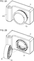
- Figs. 2A and 2B are external perspective views of the camera body 10 and first lens 100 according to the embodiment of the present invention.
- Fig. 2A illustrates a state in which the first lens 100 is mounted to the camera body 10
- Fig. 2B illustrates a state in which the first lens 100 has been removed from the camera body 10.
- the camera body 10 and first lens 100 have a ring-shaped camera mount 201 and ring-shaped lens mount 301, which each have contact faces which are parallel in a direction orthogonal to the optical axis and as such are arranged to cooperate with each other in use.
- the above-described optical axis is parallel to a center axis passing through the center of an aperture of the camera mount and lens mount.
- the center axis of the camera mount 201 and the center axis of the lens mount 301 are same as each of the optical axes of the camera mount 201 and lens mount 301, respectively.
- a configuration may be employed where this is realized by differing the center axis of the mount from the optical axis.
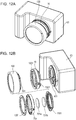
- Figs. 3A and 3B are disassembled perspective views of the camera body 10 and first lens 100 according to the embodiment of the present invention.
- Fig. 3A illustrates a disassembled perspective view of the camera body 10
- Fig. 3B illustrates a disassembled perspective view of the first lens 100.
- a first optical axis (first center axis) 3000 indicates a light flux passing through the center of the camera mount 201 of the camera body 10 as illustrated in Fig. 3A .
- an optical axis 3001 is an axis for describing a light flux representing an optical image of a subject that is guided by the first lens 100.
- a lock pin 202 is a first restricting member (lock member) for restricting (locking) the mounted state of the camera body 10 and camera accessory.
- the lock pin 202 is capable of advancing and retreating in a direction parallel to the first optical axis 3000. Specifically, when the first lens 100 is mounted to the camera body 10, the lock pin 202 enters a lock groove 301z that is a second restricting member provided to the lens mount 301, and locks the state of the first lens 100 being mounted to the camera body 10.
- the locking of the first lens 100 mounted to the camera body 10 can be disengaged by the user operating a lock disengaging member (omitted from illustration) connected to the lock pin 202, thereby retracting the lock pin 202 from the lock groove 301z. Note that even in a case of further rotating the first lens 100 and camera body 10 relative to each other in the mounting direction with the lock disengaging member operated, rotation beyond a lock abutting face 301y is restricted (see Fig. 7A ).
- the contact holding member 203 is holding means for holding later-described (see Figs. 8A and 8B ) multiple contact pins (electrical contact unit) 203a through 203k and 203m, provided on the camera body 10 side. Note that in the present embodiment, the contact pins and contact faces corresponding to the above-described terminals are denoted by the same part numerals as the terminals for the sake of description.
- a camera body member 204 is a camera housing that holds the members of the camera body 10. Specifically, the above-described camera mount 201 and contact holding member 203 are fastened to the camera body member 204 by camera mount fastening screws 205a through 205d and contact holding member fastening screws that are omitted from the illustration. Also, camera mount fastening screws 205a through 205d are positioned at positions where none of multiple leaf springs 206a, 206b, and 206c are positioned on the camera mount 201. Furthermore, camera mount fastening screws 205a through 205d are exposed at the contact faces of the camera mount 201 which is in contact with the contact face of the lens mount 301. Although the camera body member 204 holds an unshown imaging unit to which the aforementioned imaging sensor 11 is mounted, and a shutter unit that is omitted from illustration, description will be omitted.
- the lens mount biasing member 206 is a biasing means at the imaging apparatus side to pull lens claws 301d and 301e, which are multiple bayonet claws provided to the later-described lens mount 301, toward the camera mount 201 side.
- the lens mount biasing member 206 has multiple leaf springs 206a, 206b, and 206c, and the bayonet claws provided to the first lens 100 are biased in the optical axis direction by the leaf springs. Note that the lens mount biasing member 206 is held between the camera mount 201 and camera body member 204 in a space formed therebetween.
- a front lens 101a and rear lens 101b are optical members making up the photography lens group 101, as illustrated in Fig. 3B . While the photography lens group 101 has multiple lenses, only the front lens 101a disposed at the subject-side end and the rear lens 101b disposed at the camera body 10 side end are illustrated in the present embodiment to simplify description.
- a lens barrel 302 is a holding member that holds the photography lens group 101.
- the lens mount 301 is fastened to the lens barrel 302 by lens mount fastening screws 304a through 304d.
- a contact face holding member 303 is holding means for holding multiple contact faces (electrical contact units) 303a through 303k and 303m provided to a later-described (see Figs. 9A and 9B ) first lens 100 side.
- the contact face holding member 303 is fastened to the lens mount 301 by lens contact holding portion fastening screws 305a and 305b.
- the lens mount fastening screws 304a through 304d are exposed at the contact faces of the lens mount 301 which is in contact with the contact face of the camera mount 201. Configuration of Bayonet Claws at Camera Body 10 Side
- Figs. 4A through 4C are diagrams exemplarily describing a case of viewing the camera mount 201 according to the embodiment of the present invention from the photographer side of the camera body 10 (rear face side of the camera body 10).
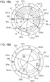
- Fig. 4A is a diagram illustrating angle ranges that camera mount claws (hereinafter referred to simply as camera claws) and camera mount recesses (hereinafter referred to simply as camera recesses) having the lock pin 202 as a reference occupy in the circumferential direction of the camera mount 201.
- the camera recesses of the camera mount 201 are notched portions between adjacent camera claws.
- Fig. 4B is a diagram illustrating angle ranges that multiple camera claws 201a through 201c occupy in the circumferential direction of the camera mount 201.
- Fig. 4C is a cross-sectional diagram taken along cross-section IVC-IVC in Fig. 4B .
- protrusions protruding from recesses in the inner radial direction at the camera mount side will be referred to as camera claws
- protrusions protruding from recesses in the outer diameter direction at the later-described lens mount (accessory mount) side will be referred to as lens mount claws.
- the side of the camera mount 201 as viewed from the side of the photographer (rear face of the camera body 10) of the camera body 10 will be referred to as rear face side, and the opposite side will be referred to as front face side (or camera accessory side).
- a first camera claw 201a, second camera claw 201b, and third camera claw 201c are provided in order, to the camera mount 201 in the circumferential direction (inner radial direction), as illustrated in Figs. 4A and 4B .
- the camera claw that is provided at a position farthest from the lock pin 202 is the first camera claw 201a.
- the second camera claw 201b and third camera claw 201c are then consecutively provided in order from the first camera claw 201a in a clockwise direction.
- recesses which are a first camera recess 201d, second camera recess 201e, and third camera recess 201f are provided in order, to the camera mount 201 in the circumferential direction (inner radial direction).
- the recess that is provided at a position nearest to the lock pin 202 is the second camera recess 201e.
- the third camera recess 201f and first camera recess 201d are then consecutively provided in order from the second camera recess 201e in a clockwise direction.
- a fitting member 201x that restricts movement of the camera accessory in a direction parallel to the optical axis when the camera accessory is mounted, is provided to the camera mount 201 side in the circumferential direction.
- the diameter of the fitting member 201x in a direction orthogonal to the optical axis at the camera mount 201 is the mount diameter.
- the camera claws of the camera body 10 are inserted into the lens mount recesses of the first lens 100, and the lens mount claws at the first lens 100 side are inserted into the camera recesses at the camera body 10 side.
- This state is a mounting start state (first state).
- accessory mount recesses will be referred to simply as accessory recesses, and accessory mount claws will be reference to simply as accessory claws.
- this is lens recesses and lens claws.
- the camera mount 201 and lens mount 301 are then rotated relative to each other from the mounting start state, whereby the camera claws and lens claws engage in the radial direction orthogonal to the optical axis, and transition to a state where the lens claws are biased by the above-described lens mount biasing member 206.
- this state relative positional relation between the camera body 10 and the first lens 100 transitions to a locked state where the lock pin 202 has fit into the lock groove 301z as described above.
- This state is a mounting complete state (second state). Note that in the mounting complete state, contact of corresponding terminals at the camera mount 201 and lens mount 301 is complete.
- the camera claws and accessory claws are so-called bayonet claws, and as described above, have shapes so that the first lens 100 can be mounted (can be coupled) to the camera body 10 by the so-called bayonet coupling method by engaging of the camera claws and accessory claws.
- the end portions are denoted with part numerals in order from the first camera claw 201a in the clockwise direction, when viewing the camera mount 201 from the rear face side, as described above.
- angles that the camera claws and camera recesses occupy in the circumferential direction of the camera mount 201 are stipulated as follows in the present embodiment.
- the angle ⁇ a 48°
- the angle ⁇ b 40°
- the angle ⁇ c 92°
- the angle is 57°
- the angle is 66°
- the angle is 57°.
- the angles in the clockwise direction where the camera claws are disposed in the circumferential direction of the camera mount 201 with the position of the lock pin 202 (referred to as reference position) as a reference are stipulated as follows.
- the first camera claw 201a is disposed between 169° to 217° with the reference position as a start point.
- the second camera claw 201b is disposed between 274° to 314° with the reference position as a start point.
- the third camera claw 201c is disposed between 20° to 112° with the reference position as a start point.
- the third camera claw 201c overlaps a first camera mount center line 3003 that extends in the vertical direction from the center axis parallel with the optical axis of the camera mount 201 in the radial direction of the camera mount 201.
- the first camera mount center line 3003 is a line that, in a normal position of the camera body 10 where the lock pin 202 is situated at the left side when viewing the camera mount 201 from the front face side, extends in the gravitational direction and the opposite direction from the gravitational direction, from the center (optical axis) of the camera mount 201.
- the first camera mount center line 3003 is a vertical line that passes through the optical axis in a normal position of the camera.
- the first camera mount center line 3003 is a vertical line that passes though the center of the camera mount 201 and orthogonal to the center axis of the camera mount 201 when the camera body 10 is placed on a horizontal plane.
- a line that, in a vertical position of the camera body 10 where the lock pin 202 is situated at the top side when viewing the camera mount 201 from the front face side, extends in the gravitational direction and the opposite direction from the gravitational direction, from the center (optical axis) of the camera mount 201 is a second camera mount center line 3002. That is to say, the second camera mount center line 3002 is a horizontal line that passes through the optical axis when the camera body 10 is in the normal position. The second camera mount center line 3002 overlaps the lock pin 202 and first camera claw 201a in the radial direction of the camera mount 201. Note that the first camera mount center line 3003 and the second camera mount center line 3002 are generally orthogonal.
- Figs. 5A and 5B are diagrams exemplarily describing engagement of the camera body 10 and first lens 100 by camera claws at a normal position of the camera body 10 according to the embodiment of the present invention.
- Fig. 5A is a diagram viewing a state where the first lens 100 is mounted to the camera body 10 from the front face side.
- Fig. 5B is a partial cross-sectional view of the camera body 10 and first lens 100 taken along cross-section VB-VB in Fig. 5A . Note that in Figs. 5A and 5B , the camera body 10 is positioned in the above-described normal position, and, in this state, a camera grip 204a provided to the camera body member 204 is situated to the left side when viewing the camera body 10 from the front face side.
- Figs. 6A and 6B are diagrams exemplarily describing engagement of the camera body 10 and first lens 100 by bayonet claws at a vertical position of the camera body 10 according to the embodiment of the present invention.
- Fig. 6A is a diagram viewing a state where the first lens 100 is mounted to the camera body 10 from the front face side.
- Fig. 6B is a partial cross-sectional view of the camera body 10 and first lens 100 taken along cross-section VIB-VIB in Fig. 6A . Note that in Figs. 6A and 6B , the camera body 10 is positioned in the above-described vertical position, and the camera grip 204a in this state is situated to the top side when viewing the camera body 10 from the front face side.
- a gap occurs between the camera and interchangeable lens in a direction orthogonal to the optical axis, due to dimensional tolerance of the two, and looseness of the lens as to the camera increases due to this gap.
- the looseness of the lens is greater the farther away from positions where the bayonet claws engage each other in the circumferential direction of the lens.
- the looseness in the gravitational direction (bowing) of the interchangeable lens as to the camera is greater due to the weight of the interchangeable lens itself.
- the third camera claw 201c that has the widest angle of the camera-side bayonet claws overlaps the first camera mount center line 3003 in the radial direction of the camera mount, as illustrated in Fig. 5B .
- the first camera mount center line 3003 overlaps the position where the third camera claw 201c and a later-described third lens claw 301f are engaged.
- looseness (bowing) of the camera accessory such as the first lens 100 or the like mounted to the camera body 10 in the gravitational direction, can be suppressed in the normal position of which the frequency of usage is highest for operating the imaging apparatus, for example.
- the gap ⁇ 1 illustrated in Fig. 5B can be kept from becoming large, so looseness of the first lens 100 as to the camera body 10 in the direction indicated by the arrow in Fig. 5B can be suppressed.
- the first camera claw 201a overlaps the second camera mount center line 3002, as illustrated in Fig. 6B in the radial direction of the camera mount 201.
- the second camera mount center line 3002 overlaps the position where the first camera claw 201a and a later-described first lens claw 301d are engaged.
- looseness (bowing) of the camera accessory such as the first lens 100 or the like mounted to the camera body 10 in the gravitational direction, can be suppressed in the vertical position of the imaging apparatus as well, for example.
- the gap ⁇ 2 illustrated in Fig. 6B can be kept from becoming large, so looseness of the first lens 100 as to the camera body 10 in the direction indicated by the arrow in Fig. 6B can be suppressed.
- the angle of the third camera claw 201c in the circumferential direction of the camera mount 201, situated at the top side in a case where the camera body 10 is at the normal position, is greater than the sum of angles of the first claw 201a and second claw 201b situated at the lower side, as illustrated in Fig. 4B . More precisely, the total sum of angles in the circumferential direction of the camera claws provided to the camera mount 201 is greater at the upper side of the second camera mount center line as a reference as compared to the lower side.
- the layout of the camera claws and recesses is decided so as to satisfy the two following expressions. ⁇ c ⁇ ⁇ a + ⁇ b ⁇ a 1 + ⁇ c > ⁇ a 2 + ⁇ b
- the strength of camera claws at the upper side of the second camera mount center line 3002 (opposite side from the gravitational direction) that indicates the horizontal direction of the camera mount 201 can be made to be greater than the camera claws at the lower side (gravitational direction). Accordingly, in the normal position of the camera body 10 regarding which the frequency of usage is highest in a state where the first lens 100 is mounted, the camera body 10 according to the present embodiment can reduce looseness (bowing) of the first lens 100 as to the camera body 10 in the gravitational direction.
- FIGs. 7A and 7B are diagrams exemplarily describing a case of viewing the lens mount 301 according to the embodiment of the present invention from the rear face side in a state where the first lens 100 is mounted to the camera body 10 (side where the camera body 10 is attached).
- Fig. 7A exemplarily describes angles of the claws and recesses in the circumferential direction at the lens mount 301 side
- Fig. 7B is a cross-sectional view taken along cross-section VIIB-VIIB in Fig. 7A . Note that in the following description, the camera body 10 is positioned in the normal position in the state illustrated in Figs. 7A and 7B .
- a first lens claw 301d, second lens claw 301e, and third lens claw 301f are provided in order, to the lens mount 301 in the circumferential direction (inner radial direction), as illustrated in Figs. 7A .
- the lens claw that is provided at a position farthest from the lock groove 301z is the first lens claw 301d.
- the second lens claw 301e and third lens claw 301f are then consecutively provided in order from the first lens claw 301d in a clockwise direction.
- recesses which are a first lens recess 301a, second lens recess 301b, and third lens recess 301c are provided in order, to the lens mount 301 in the circumferential direction (inner radial direction).
- the recess that is provided at a position nearest to the lock groove 301z is the third lens recess 301c.
- the first lens recess 301a and second lens recess 301b are then consecutively provided in order from the third lens recess 301c in a clockwise direction.
- a fitting member 301x that restricts movement in a direction parallel to the optical axis of the imaging apparatus when mounted on the imaging apparatus, is provided to the lens mount 301 side in the circumferential direction.
- the diameter of the fitting member 301x in a direction orthogonal to the optical axis at the lens mount 301 side is the mount diameter.
- the end portions are denoted with part numerals in order from the first lens claw 301d in the clockwise direction, when viewing the lens mount 301 from the rear face side, as described above.
- the angles that the lens claws and lens recesses occupy in the circumferential direction of the lens mount 301 are stipulated as follows in the present embodiment.
- the angle ⁇ d 53°
- the angle ⁇ e 62°
- the angle ⁇ f 53°
- the angle is 52°
- the angle is 44°
- the angle is 96°.
- the angles where the lens claws are disposed in the circumferential direction of the lens mount 301 with the position of the lock groove 301z (referred to as reference position) as a reference in the clockwise direction are stipulated as follows.
- the first lens claw 301d is disposed between 159° to 212° with the reference position as a start point.
- the second lens claw 301e is disposed between 256° to 318° with the reference position as a start point.
- the third lens claw 301f is disposed between 54° to 107° with the reference position as a start point.
- the second lens claw 301e overlaps a first lens mount center line 3005 that extends in the vertical direction of the lens mount 301, in the radial direction of the lens mount 301.
- the third lens claw 301f overlaps the first lens mount center line 3005 in the radial direction of the lens mount 301.
- the first lens mount center line 3005 is a line that, in a normal position of the camera body 10 to which the first lens 100 has been mounted, extends in the gravitational direction and the opposite direction from the gravitational direction, from the center (optical axis) of the camera mount 301.
- the first lens mount center line 3005 is a vertical line that passes through a center of the lens mount 301 and is orthogonal to the center axis of the lens mount 301 when the camera body 10 to which the first lens 100 is attached is placed on a horizontal plane.
- This second lens mount center line 3006 overlaps the lock groove 301z and first lens claw 301d in the radial direction of the lens mount 301.
- the first lens mount center line 3005 and second lens mount center line 3006 are mutually orthogonal.
- the second lens claw 301e and third lens claw 301f overlap the first lens mount center line 3005 in the radial direction of the lens mount 301, as illustrated in Fig. 7A .
- the first lens mount center line 3005 overlaps two positions of engaging positions between lens claws and camera claws. In this case for example, in the normal position of the imaging apparatus 10 regarding which the frequency of usage is highest, looseness (bowing) of the first lens 100 mounted to the camera body 10 in the gravitational direction can be reduced.
- the first lens claw 301d overlaps the second lens mount center line 3006 in the radial direction of the lens mount 301, as illustrated in Fig. 7A .
- the second lens mount center line 3006 overlaps the position where the first lens claw 301d and the first camera claw 201a engage.
- looseness (bowing) of the first lens 100 mounted to the camera body 10 in the gravitational direction can be reduced.
- the second camera mount center line 3002 and second lens mount center line 3006 overlap a lock region where the lock pin 202 and lock groove 301z are fit, as described above.
- the engaging position of the first camera claw 201a and first lens claw 301d and the above-described lock region overlap the mount center lines extending in the gravitational direction and the opposite direction thereof.
- looseness (bowing) of the first lens 100 mounted to the camera body 10 in the gravitational direction can be suppressed even more effectively.
- Figs. 8A and 8B are external perspective views viewing a camera mount 201 according to the embodiment of the present invention from the front face side (subject side).
- Fig. 8A is an external view of the camera mount 201 from the optical axis direction
- Fig. 8B is an external perspective view of the camera mount 201 from above.
- the contact holding member 203, and contact pins 203a through 203k and 203m that are held by the contact holding member 203 are disposed following the circumferential direction of the camera mount 201 on the inner side of the camera mount 201, as illustrated in Fig. 8A .
- An array line on which the contact points are disposed is illustrated in Fig. 8A as an array line 3007.
- the contact pins 203a through 203k and 203m are movable pins that can advance and retreat (protrude and retract) in a direction parallel to the optical axis 3000, and are biased from behind toward the first lens 100 side by leaf springs (omitted from illustration).
- the contact pins 203a through 203k and 203m have the functions of the above-described respective terminals, and the part numerals by which the contact pins are denoted are the same as those of the terminals, to facilitate description.
- the contact pins 203a, 203b, 203c, and 203d are higher in the direction parallel to the optical axis 3000 (toward the front face) as compared to the other contact pins.
- a configuration may be employed where this is realized by differing the amount of protrusion of the contact pins from the contact holding member 203.
- the contact pins at the camera side and the contact face on the lens side slide over each other.
- contact pins other than the contact pin situated at the edge in the rotational direction to complete mounting of the interchangeable lens slide over one or another contact face provided to the lens side Accordingly, the more times the camera accessory is attached/detached to/from the camera, the more the contact pins and contact faces are worn.
- the contact height of the camera-side contact pins and the interchangeable-lens-side contact faces are differed in a direction parallel to the optical axis 3000, between an upper tier and a lower tier.
- the contact holding member 203 has a step (height level difference) in a direction parallel to the optical axis 3000, with the contact pins 203a through 203d being provided to the upper tier, and the contact pins 203e through 203k and 203m being provided to the lower tier.
- the contact face holding member 303 also is stepped in a direction parallel to the optical axis 3001, with the contact faces 303a through 303d provided to the lower tier, and the contact faces 303e through 303k and 303m provided to the upper tier.
- the upper tier of the contact holding member 203 at the camera mount 201 side is a tier protruding toward the front face side (subject side) of the first lens 100 when the first lens 100 is mounted to the camera body 10.
- the lower tier of the contact holding member 203 is a tier recessed toward the rear face side (imaging sensor 11 side) of the camera body 10.
- the upper tier of the contact face holding member 303 at the lens mount 301 side is a tier protruding toward the rear face side (imaging sensor 11 side) of the first lens 100 when the first lens 100 is mounted to the camera body 10.
- the lower tier of the contact face holding member 303 is a tier recessed to the front face side (subject side) of the camera body 10.
- the contact pins provided to the upper tier side of the contact holding member 203 and the contact faces provided to the lower tier side of the contact face holding member 303 are electrically in contact among corresponding terminals. Also, in a case where the lens mount 301 is mounted to the camera mount 201, the contact pins provided to the lower tier side of the contact holding member 203 and the contact faces provided to the upper tier side of the contact face holding member 303 are electrically in contact among corresponding terminals.
- the steps at the camera mount 201 side and lens mount 301 side have a mutually engageable shape, so when mounting the lens mount 301 to the camera mount face A, the contact pins at the camera side and contact faces at the lens side that are provided to different steps do not come into contact.
- the contact pins 203e through 203k and 203m do not come into contact with the contact faces 303a through 303d. Also, when relatively rotating the first lens 100 as to the camera body 10 from the mounting completed state to the mounting start state, the contact pins 203e through 203k and 203m do not come into contact with the contact faces 303a through 303d. That is to say, the number of times of sliding between contact pins and contact faces can be reduced at both the camera mount 201 side and lens mount 301 side.
- the contact pins at the camera body 10 side and the contact faces at the first lens 100 side are all in a non-contact state in the mounting start state of the first lens 100 as to the camera body 10, so short-circuiting among terminals before completion of mounting of the first lens 100 can be prevented.
- Figs. 9A and 9B are external perspective views of the lens mount 301 according to the embodiment of the present invention, as viewed from the side to which the camera mount 201 is mounted (rear face side).
- Fig. 9A is an external view of the lens mount 301 from the optical axis direction
- Fig. 9B is an external perspective view of the lens mount 301 from above.
- the contact face holding member 303, and contact faces 303a through 303k and 303m that are held by the contact face holding member 303 are disposed on the inner side of the lens mount 301, following the circumferential direction of the lens mount 301, as illustrated in Fig. 9A .
- An array line on which the contact points are disposed is illustrated in Fig. 9A as an array line 3008.
- the contact faces 303a through 303k and 303m have the functions of the above-described respective terminals, and the part numerals by which the contact faces are denoted are the same as those of the terminals, to facilitate description.
- the contact faces 303a, 303b, 303c, and 303d are lower in the direction parallel to the optical axis 3001 as compared to the other contact faces.
- the above-described configuration is realized by differing the amount of protrusion of the contact face holding member 303 in the optical axis direction in the present embodiment.
- the contact faces 303a through 303d do not come into contact with the contact pins 203e through 203k and 203m. Also, when relatively rotating the first lens 100 as to the camera body 10 from the mounting completed state to the mounting start state, the contact faces 303a through 303d do not come into contact with the contact pins 203e through 203k and 203m. That is to say, the number of times of sliding between contact pins and contact faces can be reduced at both the camera mount 201 side and lens mount 301 side.
- the contact face holding member 303 has a first guiding inclined face 303n and a second guiding inclined face 303p for drawing corresponding contact pins toward the rear face direction (imaging sensor 11 side) when mounting the first lens 100 to the camera body 10, as illustrated in Fig. 9B .
- the contact pressure of the contact pins provided to the camera body 10 side as to the contact face holding member 303 gradually changes, whereby deformation and wear of the contact pins provided to the camera body 10 can be reduced.
- Figs. 10A and 10B are diagrams exemplarily describing a contact state between terminals on the camera body 10 and first lens 100 according to the embodiment of the present invention.
- Fig. 10A is a diagram for describing the contact state of the terminals in the mounting start state where mounting of the first lens 100 to the camera body 10 has been started.
- Fig. 10B is a diagram for describing the contact state of the terminals in the mounting completed state where mounting of the first lens 100 to the camera body 10 has been completed. Note that in the state illustrated in Fig.
- the contact pins 203m and 203k at the camera mount 201 side in the optical axis direction overlap the contact faces 303a and 303b at the lens mount face B side.
- the height of the contact holding member 203 and the contact face holding member 303 in the direction parallel with the optical axis is made to differ for each region, as described above, none of the contact pins and contact faces come into contact in the state illustrated in Fig. 10A .
- the state illustrated in Fig. 10B is a state where the first lens 100 has been rotated by generally 60° as to the camera body 10 from the state illustrated in Fig. 10A toward the direction indicated by the arrow (see Fig. 10A ). That is to say, in the present embodiment, the relative rotational angle of the camera body 10 and first lens 100 from the mounting start state to the mounting completed state is generally 60°. Note that in the state illustrated in Fig. 10B , the lock pin 202 is in the state of fitting the lock groove 301z (locked).
- Rotating the first lens 100 by generally 60° as to the camera body 10 guides the first lens claw 301d into the rear face side (imaging sensor 11 side) of the first camera claw 201a and the two are engaged with each other in the optical axis direction.
- the second lens claw 301e is guided into the rear face side (imaging sensor 11 side) of the second camera claw 201b, and these are engaged with each other in the optical axis direction.
- the third lens claw 301f is guided into the rear face side (imaging sensor 11 side) of the third camera claw 201c, and these are engaged with each other in the optical axis direction.
- the positions of the lens claws provided to the first lens 100 are positioned by being biased toward the rear face side by the lens mount biasing member 206 provided to the camera mount 201 side, thereby coupling the camera body 10 and the first lens 100.
- the contact pins at the camera body 10 side are pressed toward the rear face side (imaging sensor 11 side) by the first guiding inclined face 303n and second guiding inclined face 303p.
- the contact pins of the camera body 10 come into contact with corresponding places on the contact faces 303a through 303k and 303m at the lens mount 301 side in a state of being pressed, and come into contact with the respectively corresponding contact faces in the mounting completed state.
- the contact pin 203m provided to the camera mount 201 side and the contact face 303e provided to the lens mount 301 start coming into contact first.
- Figs. 11A and 11B are diagrams describing the first conversion adapter 40 that is mountable to the camera body 10, and a second lens unit 50.
- Fig. 11A illustrates an external perspective view of the second lens unit 50 having been mounted to the camera body 10 via the first conversion adapter 40.
- Fig. 11B illustrates an external perspective view of a state where the camera body 10, first conversion adapter 40, and second lens unit 50 have each been detached.
- the second lens unit (hereinafter referred to as second lens) 50 has a lens mount 501 that is long in flange focal distance, but has the same mount diameter as the camera mount 201, as to the camera body 10. That is to say, the second lens 50 has the same mount diameter as the above-described first lens 100, but unlike the first lens 100, is a camera accessory that is not compatible with direct mounting to the camera body 10.
- Figs. 12A and 12B are diagrams for describing the second conversion adapter 70 the is mountable to a camera body 60 and the first lens 100.
- Fig. 12A illustrates an external perspective view of a state where the first lens 100 is mounted to the camera body 60 via the second conversion adapter 70
- Fig. 12B illustrates an external perspective view where the camera body 60, second conversion adapter 70, and first lens 100 have each been detached.
- the camera body 10 and camera body 60, and the first lens 100 and second lens 50 have the same mount diameter, it is difficult for a user to judge which imaging apparatuses and which lens units have flange focal distances that are compatible for direct mounting.
- lens units that are compatible can be directly mounted to a certain imaging apparatus, so that imaging apparatuses and lens units that have mutually incompatible flange focal distances are not erroneously directly mounted.
- a conversion adapter needs to be interposed between the two to adjust the flange focal distance.
- the focal point may not be accurately formed, as described above.
- the one side and other side of the conversion adapter preferably have configurations to restrict imaging apparatuses and camera accessories that are directly mountable.
- a conversion adapter is preferable where one end side is only mountable to this imaging apparatus, and the other end side is only mountable to this lens unit. Also, in a case of mounting a lens unit having a short flange focal distance to an imaging apparatus having a long flange focal distance, a conversion adapter is preferable where one end side is only mountable to this imaging apparatus, and the other end side is only mountable to this lens unit.
- the first conversion adapter 40 has the lens mount 1301 attached to an adapter barrel 40a by fastening screws (omitted from illustration), at one end side in the optical axis direction.
- This lens mount 1301 is an accessory mount that is detachable from the camera mount 1201 provided to the camera body 10 described above.
- a camera mount 1401 is attached to the adapter barrel 40a by fastening screws (omitted from illustration), at the other end side of the first conversion adapter 40 in the optical axis direction.
- This camera mount 1401 is a camera mount that is detachable from the lens mount 1501 of the second lens 50. Note that the camera mount 1401 of the first conversion adapter 40 is attached so that the imaging plane of the imaging sensor 11 of the will be situated at a position corresponding to the flange focal distance of the second lens 50.
- the second conversion adapter 70 has the lens mount 1501 attached to an adapter barrel 70a by fastening screws (omitted from illustration), at one end side in the optical axis direction.
- This lens mount 1501 is an accessory mount that is detachable from the camera mount 1401 provided to the camera body 60.
- the camera mount 1201 is attached to the adapter barrel 70a by fastening screws (omitted from illustration), at the other end side of the second conversion adapter 70 in the optical axis direction.
- This camera mount 1201 is a camera mount that is detachable from the lens mount 1301 of the first lens 100, as described above.
- first optical member 701a and a second optical member 701b are provided to the second conversion adapter 70, between the adapter barrel 70a and the lens mount 1501 in the optical axis direction.
- the first optical member 701a and second optical member 701b enable the second conversion adapter 70 to extend length of the flange focal distance of the first lens 100 in accordance with the imaging plane of the imaging sensor disposed in the camera body 60. While the optical members have been illustrated as two lenses for the sake of convenience, this is not restrictive.
- Figs. 13A through 13C are diagrams for exemplarily describing displacement angles of bayonet claws in the camera mount 1401 provided on one end of the first conversion adapter 40.
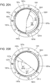
- Fig. 13A is a diagram illustrating angle ranges that camera claws and camera recesses occupy in the circumferential direction of the camera mount 1401 with the lock pin 1401z as a reference, as viewed from the rear face side (camera body 10 side).
- Fig. 13A is a diagram illustrating angle ranges that camera claws and camera recesses occupy in the circumferential direction of the camera mount 1401 with the lock pin 1401z as a reference, as viewed from the rear face side (camera body 10 side).
- FIG. 13B is a diagram illustrating angle ranges that multiple camera claws 1401a through 1401c occupy in the circumferential direction of the camera mount 1401, as viewed from the rear face side (camera body 10 side).
- Fig. 13C is a cross-sectional diagram taken along cross-section XIIIB-XIIIB in Fig. 13B .
- the first conversion adapter 40 is a mount adapter used for mounting the second lens unit 50 that has a long flange focal distance to the camera body 10 that has a short flange focal distance. Accordingly, it is preferable for the first conversion adapter 40 to be configured such that the camera body 60 that has a long flange focal distance cannot be directly mounted to the lens mount 1301, and the first lens 100 that has a short flange focal distance cannot be directly mounted to the camera mount 1401. According to this configuration, the positional relation of claws and recesses can be satisfied so that the lens mount 1301 provided to one end (first end) of the first conversion adapter 40 and the camera mount 1401 provided to the other end (second end) cannot each be directly mounted.
- a first camera claw 1401a, second camera claw 1401b, and third camera claw 1401c are provided in order, to the camera mount 1401 in the circumferential direction (inner radial direction).
- the camera claw that is provided at a position farthest from the lock pin 1401z is the first camera claw 1401a.
- the second camera claw 1401b and third camera claw 1401c are then consecutively provided in order from the first camera claw 1401a in a clockwise direction.
- recesses which are a first camera recess 1401d, second camera recess 1401e, and third camera recess 1401f are provided in order, to the camera mount 1401 in the circumferential direction (inner radial direction).
- the recess that is provided at a position nearest to the lock pin 1401z is the second camera recess 1401e.
- the third camera recess 1401f and first camera recess 1401d are then consecutively provided in order from the second camera recess 1401e in a clockwise direction.
- a fitting member 1401x that restricts movement of the camera accessory in a direction parallel to the optical axis when the camera accessory is mounted, is provided to the camera mount 1401 side.
- the diameter of the fitting member 1401x in a direction orthogonal to the optical axis at the camera mount 1401 side is the mount diameter.
- the way of bayonet coupling of the first conversion adapter 40 and second lens 50 is the generally the same as the way of bayonet coupling of the camera body 10 and first lens 100 described above, so description will be omitted.
- the end portions are denoted with part numerals in order from the first camera claw 1401a in the clockwise direction, when viewing the camera mount 1401 from the rear face side, as described above.
- the angles that the camera claws and camera recesses occupy in the circumferential direction of the camera mount 1401 (angle ranges) in the first conversion adapter 40 according to the present embodiment are stipulated as follows.
- the angle ⁇ 1 56°
- the angle ⁇ 2 62°
- the angle ⁇ 3 62°
- the angle is 57°
- the angle is 66°
- the angle is 57°. That is to say the camera mount 1401 has different angles for the camera claws with respect to the above-described camera mount 1201 of the camera body 10, but the angles of the camera recesses are the same.
- the angles where the camera claws are disposed on the circumferential direction of the camera mount 1401 with the position of the lock pin 402 (referred to as reference position) as a reference are stipulated as follows.
- the first camera claw 1401a is disposed between 159° to 215° with the reference position as a start point.
- the second camera claw 1401b is disposed between 272° to 334° with the reference position as a start point.
- the third camera claw 1401c is disposed between 40° to 102° with the reference position as a start point.
- Figs. 14A and 14B are diagrams exemplarily describing angles of disposing the bayonet claws on the lens mount 1301 provided to the other end of the first conversion adapter 40.
- Fig. 14A is a diagram illustrating angle ranges that lens claws and lens recesses occupy in the circumferential direction of the lens mount 1301 with the lock groove 1301z as a reference, as viewed from the rear face side.
- Fig. 14B is a diagram illustrating angle ranges that multiple lens recesses 1301a through 1301c occupy in the circumferential direction of the lens mount 1301, as viewed from the rear face side.
- the angles (angle ranges) that the lens recesses occupy in the circumferential direction of the lens mount 1301 are, represented by ⁇ 4 as the angle of the first lens recess 1301a and ⁇ 5 as the angle of the second lens recess 1301b, as illustrated in Fig. 14B .
- ⁇ 4 as the angle of the first lens recess 1301a
- ⁇ 5 as the angle of the second lens recess 1301b
- the angles of the claws and recesses in the circumferential direction, on the lens mount 1301 and camera mount 1401 provided to the first conversion adapter 40, will be compared.
- the angle ⁇ 5 of the second lens recess 1301b having the smallest angle is 44°
- the angle ⁇ 1 of first camera claw 1401a having the smallest angle is 56°. That is to say, the claw having the smallest angle at the camera mount 1401 side is larger than the recess having the smallest angle at the lens mount 1301 side ( ⁇ 5 ⁇ ⁇ 1).
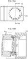
- FIGs. 15A and 15B are diagrams exemplarily describing a mounting method of a predetermined imaging apparatus 1000 and a predetermined lens unit 2000 having claws and recesses that interfere with each other.
- Fig. 15A is a diagram exemplarily describing a frontal view of partway through mounting a predetermined lens unit to a predetermined imaging apparatus that have claws and recesses that interfere with each other.
- Fig. 15B is a cross-sectional view taken along cross-section XVB-XVB in Fig. 15A .
- a camera claw is inserted into a lens recess, and from this state, the lens mount and camera mount are rotated relatively to each other, as illustrated in Figs. 15A and 15B .
- this interference with each other is resolved during the relative rotation of the lens mount and camera mount, and transition can be made to a state where the camera claw is inserted into this lens recess.
- the lens unit can be mounted to the camera body.
- the claws and recesses on the lens mount 1301 side and camera mount 1401 side are disposed such that the angle of a predetermined lens recess adjacent to a reference lens claw is smaller than the angle of two camera claws adjacent to a reference camera recess.
- the angles ⁇ 4 and ⁇ 5 of the first lens recess 1301a and second lens recess 1301b adjacent to the first lens claw 1301d are smaller than the angles ⁇ 1 and ⁇ 2 of the first camera claw 1401a and second camera claw 1401b adjacent to the first camera recess 1401d.
- ⁇ 4 (52°) is smaller than ⁇ 1 (56°)
- ⁇ 5 (44°) is smaller than ⁇ 2 (62°) ( ⁇ 4 ⁇ ⁇ 1, ⁇ 5 ⁇ ⁇ 2). Accordingly, even if an attempt is made to insert the first lens claw 1301d into the first camera recess 1401d, the second lens claw 1301e interferes with the second camera claw 1401b in a sure manner, as well does the third lens claw 1301f with the first camera claw 1401a, as illustrated in Figs. 16A and 16B .
- Figs. 16A and 16B are diagrams exemplarily describing the way in which claws interfere with each other when attempting to mount the lens mount 1301 side to the camera mount 1401 side according to the embodiment of the present invention.
- Fig. 16A illustrates the way in which the third lens claw 1301f and the first camera claw 1401a interfere
- Fig. 16B illustrates the way in which the second lens claw 1301e and the second camera claw 1401b interfere.
- incompatible lens units and imaging apparatuses, and the mount portions of conversion adapters are configured so that two claws of each other out of the claws that an incompatible lens unit and imaging apparatus have interfere with each other in the present embodiment. According to this configuration, the risk of an incompatible lens unit being erroneously mounted to an imaging apparatus, or an incompatible lens unit and imaging apparatus being erroneously mounted to mount units provided to both ends of a conversion adapter, can be reduced.
- the present embodiment further takes a configuration where the angles of at least two adjacent lens recesses are smaller than the angles of all camera claws.
- the angles ⁇ 4 and ⁇ 5 of the first lens recess 1301a and second lens recess 1301b in the circumferential direction are smaller than the angles ⁇ 1 through ⁇ 3 of the first through third camera claws 1401a through 1401c in the circumferential direction.
- the relation between the claws and recesses at the lens mount 1301 side and the camera mount 1401 side according to the present embodiment satisfy ⁇ 4 ⁇ ⁇ 1, ⁇ 4 ⁇ ⁇ 2, ⁇ 4 ⁇ ⁇ 3, ⁇ 5 ⁇ ⁇ 1, ⁇ 5 ⁇ ⁇ 2, and ⁇ 5 ⁇ ⁇ 3.
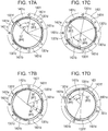
- Figs. 17A through 17D is a diagram exemplarily describing a case of attempting to insert incompatible claws into recesses at the lens mount 1301 side and camera mount 1401 side according to the embodiment of the present invention.
- Fig. 17A illustrates the way in which the third lens claw 1301f and third camera claw 1401c interfere in a case of attempting to insert the first lens claw 1301d into the third camera recess 1401f.
- Fig. 17B illustrates the way in which second lens claw 1301e and first camera claw 1401a interfere in a case of attempting to insert the first lens claw 1301d into the third camera recess 1401f.
- Fig. 17A illustrates the way in which the third lens claw 1301f and third camera claw 1401c interfere in a case of attempting to insert the first lens claw 1301d into the third camera recess 1401f.
- Fig. 17B illustrates the way in which second lens claw 1301e and first camera claw 1401a interfere in a case of attempting
- FIG. 17C illustrates the way in which the third lens claw 1301f and second camera claw 1401b interfere in a case of attempting to insert the first lens claw 1301d into the second camera recess 1401e.
- Fig. 17D illustrates the way in which the second lens claw 1301e and third camera claw 1401c interfere in a case of attempting to insert the first lens claw 1301d into the second camera recess 1401e.
- the lens claws and camera claws interfere in at least two places in the present embodiment, regardless of the relative rotational angle of the lens mount 1301 and camera mount 1401. According to this configuration, erroneous mounting of a lens unit and conversion adapter having the lens mount 301 or the lens mount 1301 to an imaging apparatus and conversion adapter having the camera mount 401 or the camera mount 1401 can be prevented even more effectively.
- the second conversion adapter 70 is a mount adapter used for mounting the first lens 100 that has a short flange focal distance to the camera body 60 that has a long flange focal distance.
- the lens mount 1501 is provided at one end (third end) side of the second conversion adapter 70, and the camera mount 1201 is provided at the other end (fourth end).
- the camera mount 1201 of the second conversion adapter 70 has the same configuration as the camera mount 1201 of the camera body 10 that is the first imaging apparatus described above.
- the lens mount 1501 of the second conversion adapter 70 has the same configuration as the lens mount 1501 of the second lens 50 described above.
- the second conversion adapter 70 prefferably be configured such that the camera body 10 that has a short flange focal distance cannot be directly mounted to the lens mount 1501, and the second lens 50 that has a long flange focal distance cannot be directly mounted to the camera mount 1201.
- This configuration can be realized by satisfying the positional relation of claws and recesses so that the lens mount 1501 provided to one end (third end) of the second conversion adapter 70 and the camera mount 1201 provided to the other end (fourth end) cannot each be directly mounted.
- Figs. 18A and 18B are diagrams exemplarily describing angles of disposing bayonet claws in the camera mount 1201 provided on one end of the second conversion adapter 70.
- Fig. 18A is a diagram illustrating angle ranges that camera claws and camera recesses occupy in the circumferential direction of the camera mount 1201 with the lock pin 1202 as a reference, as viewed from the rear face side.
- Fig. 18B is a diagram illustrating angle ranges that, regarding multiple camera claws 1201a through 1201c, the claws occupy in the circumferential direction of the camera mount 1201, as viewed from the rear face side. Note that the angles of disposing the claws and recesses on the camera mount 1201 of the second conversion adapter 70 are the same as the camera mount 201 of the camera body 10 described earlier, so description will be omitted.
- the angle from the sixth end 1201c2 of the third camera claw 1201c to the third end 1201b1 of the second camera claw 1201b, in the circumferential direction of the camera mount 1201 including the first camera claw 1201a, is ⁇ 6 (162°).
- the angle from the second end 1201a2 of the first camera claw 1201a to the fifth end 1201c1 of the third camera claw 1201c, in the circumferential direction of the camera mount 1201 including the second camera claw 1201b, is ⁇ 7 (163°).
- the angle from the fourth end 1201b2 of the second camera claw 1201b to the first end 1201a1 of the first camera claw 1201a, in the circumferential direction of the camera mount 1201 including the third camera claw 1201c, is ⁇ 8 (215°).
- Figs. 19A through 19C are diagrams exemplarily describing angle so disposing bayonet claws in a lens mount 1501 provided on the other end of the second conversion adapter 70.
- Fig. 19A is a diagram illustrating angle ranges that lens claws and lens recesses occupy in the circumferential direction of the lens mount 1501 with the lock groove 1501z as a reference, as viewed from the rear face side.
- Fig. 19B is a diagram illustrating angle ranges where recesses are provided regarding the multiple lens recesses 1501a through 1501c in the circumferential direction of the lens mount 1501, as viewed from the rear face side.
- Fig. 19C is a cross-sectional diagram taken along cross-section XIXC-XIXC in Fig. 19B .
- a first lens claw 1501d, second lens claw 1501e, and third lens claw 1501f, are provided in order, to the camera mount 1501 in the circumferential direction (inner radial direction). Note that in a case of viewing the lens mount 1501 from the rear face side as illustrated in Fig. 19A , the lens claw that is provided at a position farthest from the lock groove 1501z is the first lens claw 1501d. The second lens claw 1501e and third lens claw 1501f are then consecutively provided in order from the first lens claw 1501d in a clockwise direction.
- recesses which are a first lens recess 1501a, second lens recess 1501b, and third lens recess 1501c are provided in order, to the lens mount 1501 in the circumferential direction (inner radial direction). Note that in a case of viewing the lens mount 1501 from the rear face side as illustrated in Fig. 19A , the recess that is provided at a position nearest to the lock groove 1501z is the third lens recess 1501c. The first lens recess 1501a and second lens recess 1501b are then consecutively provided in order from the third lens recess 1501c in a clockwise direction.
- the end portions are denoted with part numerals in order from the first lens claw 1501d in the clockwise direction, when viewing the lens mount 1501 from the rear face side, as described above.
- the angles that the lens claws and lens recesses occupy in the circumferential direction of the lens mount 1501 are stipulated as follows.
- the angle of the first lens claw 1501d is 53°
- the angle of the second lens claw 1501e is 62°
- the angle of the third lens claw 1501f is 53°. That is to say, the angles of the lens claws on the lens mount 1501 side are the same as the angles of the lens claws on the lens mount 1301 side described earlier.
- the angles of the lens recesses at the lens mount 1501 side differ from the angles of the lens recesses at the lens mount 1301 side described above. Specifically, the angle of the first lens recess 1501a is 60°, the angle of the second lens recess 1501b is 66°, and the angle of the third lens recess 1501c is 66°.
- the angles in the clockwise direction where the lens claws are disposed on the circumferential direction of the lens mount 1501 with the position of the lock groove 1501z (referred to as reference position) as a reference are stipulated as follows.
- the first lens claw 1501d is disposed between 157° to 210° with the reference position as a start point.
- the second lens claw 1501e is disposed between 276° to 338° with the reference position as a start point.
- the third lens claw 1501f is disposed between 44° to 97° with the reference position as a start point.
- a fitting member 1501x that restricts movement of the imaging apparatus in a direction parallel to the optical axis when mounted to the imaging apparatus is provided to the lens mount 1501 side.
- the diameter of the fitting member 1501x in a direction orthogonal to the optical axis at the camera mount 1501 side is the mount diameter.
- the mount diameters of the camera mounts and lens mounts described above are generally the same length.
- the angle from the fifth end 1501f1 of the third lens claw 1501f to the second end 1501d2 of the first lens claw 1501d, in the circumferential direction of the lens mount 1501 including the first lens recess 1501a, is ⁇ 9 (166°).
- the angle from the first end 1501d1 of the first lens claw 1501d to the fourth end 1501e2 of the second lens claw 1501e, in the circumferential direction of the lens mount 1501 including the second lens recess 1501b, is ⁇ 10 (181°).
- the angle from the third end 1501e1 of the second lens claw 1501e to the sixth end 1501f2 of the third lens claw 1501f, in the circumferential direction of the lens mount 1501 including the third lens recess 1501c, is ⁇ 11 (181°).
- angles of the claws and recesses in the circumferential direction will be compared between the camera mount 1201 and lens mount 1501 provided to the second conversion adapter 70.
- the angle (92°) of the third camera claw at the camera mount 1201 side is larger than the angles (66°) of the second and third lens recesses 1501b and 1501c that are the largest angle of the lens recesses at the lens mount 1501 side. That is to say, the angle of at least one camera claw at the camera mount 1201 side is larger than the angle of the lens recess having the largest angle at the lens mount 1501 side.
- the claws at the camera mount 1201 side and recesses at the lens mount 1501 side at least one or more camera claw and lens recess interfere with each other. Accordingly, even if an attempt is made to mount the lens unit to the camera body so that the optical axis at the camera mount 1201 side and lens mount 1501 side are generally parallel to each other, the claws and recesses interfere, so the lens unit cannot be mounted to the camera body.
- claws of the camera mount side can be inserted into recesses of the lens mount side, in the same way as the description of the first conversion adapter made above.
- the lens mount and camera mount are rotated relative to each other, and the lens unit can be mounted to the camera body.
- Figs. 20A and 20B are diagrams exemplarily describing the way in which claws interfere with each other, when attempting to mount a reference claw at the lens mount 1501 side to a reference recess at the camera mount 1201 side according to the embodiment of the present invention.
- Fig. 20A illustrates the way in which the third lens claw 1501f and the third camera claw 1201c interfere
- Fig. 20B illustrates the way in which the second lens claw 1501e and the third camera claw 1201c interfere.
- the third camera claw 1201c interferes with the second and third lens claws 1501e and 1501f.
- the total sum of the angles of one reference lens claw, another lens claw adjacent thereto in the clockwise direction, and a lens recess situated between these lens claws is taken as a third angle.
- the total sum of the angles of one reference camera recess, another camera recess adjacent thereto in the clockwise direction, and a camera claw portion situated therebetween is taken as a second angle.
- the total sum of the angles of one reference lens claw, another lens claw adjacent thereto in the counterclockwise direction, and a lens recess situated between these lens claws is taken as a first angle.
- the total sum of the angles of one reference camera recess, another camera recess adjacent thereto in the counterclockwise direction, and a camera claw portion situated therebetween, is taken as a fourth angle.
- the claws and recesses at the camera mount 1201 side and lens mount 1501 side are disposed in the circumferential direction so as to satisfy ⁇ 6 ⁇ ⁇ 9, ⁇ 6 ⁇ ⁇ 10, ⁇ 6 ⁇ ⁇ 11, ⁇ 7 ⁇ ⁇ 9, ⁇ 7 ⁇ ⁇ 10, and ⁇ 7 ⁇ ⁇ 11.
- the total sum of the angles of two claws other than the reference claw described above, and a lens recess situated therebetween, is taken as a fifth angle.
- Figs. 21A through 21D are diagrams exemplarily describing the way in which claws interfere with each other, when attempting to mount a claw other than the reference claw at the lens mount 1501 side to a reference recess at the camera mount 1201 side according to the embodiment of the present invention.
- Fig. 21A illustrates the way in which the first lens claw 1501d and the third camera claw 1201c interfere in a case of attempting to insert the second lens claw 1501e into the first camera recess 1201d.
- Fig. 21B illustrates the way in which the third lens claw 1501c and the third camera claw 1201c interfere in a case of attempting to insert the second lens claw 1501e into the first camera recess 1201d.
- Fig. 21A illustrates the way in which the first lens claw 1501d and the third camera claw 1201c interfere in a case of attempting to insert the second lens claw 1501e into the first camera recess 1201d.
- Fig. 21A illustrates the way in which the first
- FIG. 21C illustrates the way in which the second lens claw 1501e and the third camera claw 1201c interfere in a case of attempting to insert the third lens claw 1501f into the first camera recess 1201d.
- Fig. 21D illustrates the way in which the first lens claw 1501d and the third camera claw 1201c interfere in a case of attempting to insert the third lens claw 1501f into the first camera recess 1201d.
- Figs. 21A through 21D at least two lens claws and one camera claw interfere, regardless of the relative rotation angle of the lens mount 1501 and camera mount 1201 according to the present embodiment. According to this configuration, erroneous mounting of a lens unit and conversion adapter having the lens mount 501 or the lens mount 1501 to an imaging apparatus and conversion adapter having the camera mount 201 or the camera mount 1201 can be prevented even more effectively.
- Fig. 22 is a diagram exemplarily describing a state in which claws provided to the camera mount 401 side and lens mount 501 side according to the embodiment of the present invention are engaged.
- the first lens claw 1501d can be inserted into the first camera recess 1401d, as illustrated in Fig. 22 .
- Fig. 22 illustrates a state in which the camera mount 401 of the camera body 60 is engaging the lens mount 501 of the second lens 50.
- the first lens claw 501d can be inserted into the first camera recess 401d, as illustrated in Fig. 22 .
- the second lens claw 501e can be inserted into the second camera recess 401e.
- the third lens claw 501f can be inserted into the third camera recess 401f.
- the camera mount 401 side and the lens mount 501 side are a combination compatible with being directly mounted to each other.
- the camera mount 201 side and the lens mount 301 side are a combination compatible to being directly mounted to each other, as illustrated in Fig. 10A .
- the camera mount 401 (1401) corresponding to an imaging apparatus that has a long flange focal distance (e.g., the camera body 60), and the lens mount 501 (1501) corresponding to a lens unit that has a long flange focal distance (e.g., the second lens 50) can be directly mounted to each other.
- the camera mount 201 (1201) corresponding to an imaging apparatus having a short flange focal distance (e.g., the camera body 10) and the lens mount 501 (1501) corresponding to a lens unit that has a long flange focal distance (e.g., the second lens 50) cannot be directly mounted to each other.
- the camera mount 201 (1201) corresponding to an imaging apparatus that has a short flange focal distance (e.g., the camera body 10) and the lens mount 301 (1301) corresponding to a lens unit that has a short flange focal distance (e.g., the first lens 100) can be directly mounted to each other.
- the camera mount 401 (1401) corresponding to an imaging apparatus that has a long flange focal distance (e.g., the camera body 60) and the lens mount 301 (1301) corresponding to a lens unit that has a short flange focal distance (e.g., the first lens 100) cannot be directly mounted to each other.
- an imaging apparatus and camera accessory employing the configuration of the above-described embodiment can prevent erroneous mounting of an imaging apparatus and camera accessory that have generally the same mount diameter but are not mutually compatible.
- Fig. 23 is a diagram describing a frontal view of the camera body 10 according to an embodiment of the present invention.
- a total of twelve contact pins, i.e. multiple contact pins 203e through 203k and 203m, are held in the contact holding member 203 as electric terminals corresponding to multiple contact faces provided on the first lens 100 described above, for example, as illustrated in Fig. 23 .
- the contact pin 203f that is a DCL terminal is disposed at a position overlapping the first camera mount center line 3003 of the camera mount 201, in the normal position of the camera body 10, as illustrated in Fig. 23 .
- the first camera mount center line 3003 is a vertical center line that extends from the center (optical axis) of the camera mount 201 in the gravitational direction and the opposite direction from the gravitational direction, in the normal position of the camera body 10.
- This first camera mount center line 3003 also overlaps a camera accessory attachment index 201g in the radial direction of the camera mount 201, besides the contact pin 203f.
- the contact pin 203f is disposed directly beneath the attachment index 201g and the optical axis 3000 of the camera mount 201.
- the contact pin 203f is disposed at the farthest position from an imaging region (aperture) 600 of the camera body 10, or from the second lens mount center line 3002.
- the distance from the second lens mount center line 3002 to the contact pin 203f will be referred to as "distance a", as illustrated in Fig. 23 .
- a contact pin can be disposed on the first camera mount center line 3003 by employing the above-described configuration, so the contact pin 203f situated directly below the optical axis can be used as a reference for measuring positions of other contact pins, when working on the contact holding member 203 and so forth. Accordingly, the working precision and measurement precision of the contact pins on the contact holding member 203 can be improved.
- employing the above configuration enables the user to confirm the position of the first camera mount center line 3003 and the optical axis 3000, by confirming a line between the contact pin 203f and the attachment index 201g.
- the position of the first camera mount center line 3003 and the optical axis 3000 can be confirmed without providing an index indicating the position of the optical axis or the like on the camera mount 201.
- the contact pins are formed of a metal material, so in a case where the distance from the contact pins to the aperture is short, light rays reflected by the contact pins (inner reflection) may affect photography of the subject, and an image having an unnatural brightness may be obtained.
- a method is conceivable where the distance between the contact pins is shortened, and the distances from the optical axis to the contact pins in a direction parallel to the optical axis is increased overall.
- the distance between the contact pins is short, which increases the risk of contact pins sliding over contact faces when mounting the camera accessory, and of short-circuiting of contact pins due to adhesion of foreign matter to the contact pins, and so forth. Accordingly, an appropriate distance needs to be provided among the contact pins.
- the contact pin 203f situated at the generally middle portion of the camera mount 201 in the circumferential direction is disposed at the farthest position from the aperture 600 in the present embodiment.
- the contact pin 203f is situated at the farthest position from the second lens mount center line 3002, out of the multiple contact pins that the camera mount 201 has.
- the camera body 10 is configured so that the distances from the aperture 600 (or second lens mount center line 3002) to the contact pin 203a and contact pin 203m that are on the ends of the multiple contact pins on the camera mount 201 are generally the same. Note that in the present embodiment, the distances from the first camera mount center line 3003 and the contact pin 203f to the contact pin 203a and contact pin 203m are also generally the same.
- the camera body 10 is configured such that a predetermined contact pin is disposed on the first camera mount center line 3003, and distance between the pins is adjusted so that that the distances from the contact pins on the ends to the aperture are the same.
- Fig. 24 is a partially enlarged view of the camera mount 201 according to the embodiment of the present invention.
- contact pins 203a and 203b VDD terminal and VBAT terminal
- contact pins 203g and 203h DLC terminal and LCLK terminal
- An angle ⁇ formed between the contact pin 203a and contact pin 203b is formed to be greater than an angle ⁇ formed between the contact pin 203g and contact pin 203h, in the circumferential direction of the camera mount 201.
- the pitch (distance) between each of the contact pins situated to the left side from the contact pin 203f in Fig. 24 is the same as or greater than the pitch between each of the contact pins situated to the right side from the contact pin 203f in Fig. 24 .
- the pitch between the contact pins in one of the regions is greater than the pitch between the contact pins in the other of the regions.
- the contact pins used for electric power supply are situated on the region to the left side of the first camera mount center line 3003 in Fig. 24 , which is the aforementioned one of the regions.
- the contact pins used for communication are situated on the region to the right side of the first camera mount center line 3003 in Fig. 24 , which is the aforementioned other of the regions.
- the pitch between contact pins is the distance between the centers of contact pins in the circumferential direction of the camera mount 201 in the present embodiment, this is not restrictive.
- the distance between conducting portions of the contact pins, or the distance between contact points when the contact pins are electrically connected to corresponding contact faces on the accessory mount side may be used as the pitch of contact pins.
- the contact pin 203a which corresponds to the VDD terminal is a contact pin that comes into contact with one of the contact faces on the lens mount 301 side last, when mounting the first lens 100 to the camera body 10, for example.
- the contact pin 203m which corresponds to the DGND terminal is a contact pin that comes into contact with one of the contact faces on the lens mount 301 side first, when mounting the first lens 100 to the camera body 10, for example.
- the second guiding inclined face 303p that the lens mount 301 of the camera accessory corresponding to the camera mount 201 has is situated to the left side from the contact pin 203f in Fig. 24 , in a state where the camera accessory is mounted. That is to say, the region of the camera mount 201 side corresponding to the second guiding inclined face 303p is on the left side of the contact pin in Fig. 24 , and is disposed on the side with fewer contact pins with the first camera mount center line 3003 as a reference. According to this configuration, the angle between contact pins can be made greater at the side corresponding to the guiding inclined face for terminals, with the first camera mount center line 3003 as a reference.
- the number of terminals (contact pins and contact faces) provided to the camera body 10 and first lens 100 is twelve, this is not restrictive.
- the above-described configuration is applicable as long as the number of terminals is an even number of four or greater.
- the roles of terminals situated on both ends of the mount in the circumferential direction, with the first mount center line as a reference, may be different from those of the above-described terminal 203a and terminal 203m.
- using the same pitch between all terminals and disposing one terminal overlapping the first camera mount center line 3003 enables the multiple terminals to be uniformly distributed in the right and left regions with the first camera mount center line 3003 as a reference.
- the above-described configuration has been described using the camera mount 201 provided to the camera body 10 as a reference, the above-described configuration is the same at the side of the lens mount (accessory mount) 301, provided on the first lens 100 for example, as well. That is to say, in a case where the lens mount 301 has an even number of contact faces, the contact face 303f situated at the generally middle portion in the circumferential direction of the of the lens mount 301 overlaps the first lens mount center line 3005 in the radial direction of the mount.
- the contact face 303a and contact face 303m situated on both ends of the lens mount 301 in the circumferential direction have generally the same distance to the aperture 600 (or second lens mount center line 3006) in a state where the camera mount 201 is mounted to the lens mount 301.
- the pitch between contact faces included in one of the regions where there are the contact faces used for electric power supply is a greater pitch than the pitch between contact faces included in the other of the regions where there are the contact faces used for communication.
- the contact pin 203a is the last terminal to come into contact with one of the contact faces at the accessory mount side
- the contact pin 203m is the first terminal to come into contact with one of the contact faces at the accessory mount side
- this relation is inverted at the accessory side. That is to say, the contact face 303a is the first terminal to come into contact with one of the contact pins at the camera mount side
- the contact face 303m is the last terminal to come into contact with one of the contact pins at the camera mount side.
- an interchangeable lens and an intermediate accessory such as a conversion adapter and an extension adapter (extension-tube)
- an interchangeable lens and an intermediate accessory such as a conversion adapter and an extension adapter (extension-tube)
- an extension adapter extension-tube
- Any sort of camera accessory may be employed as long as it is a device that has an accessory mount capable of directly connecting (coupling) to a camera mount provided to the above-described imaging apparatuses.
- both of the camera mount and accessory mount corresponding to each other have a pair of electric terminals through which electric connection is established in a mutually mounted state
- this is not restrictive.
- a configuration may be made having electric terminals that do not correspond to each other.
- a configuration may be made where a terminal that the camera body 10 does not have is provided to a camera accessory mountable to the camera body 10.
- each mount has three claws in the circumferential direction
- the number of claws is not restricted to three, as long as the conditions of the above-described embodiment are satisfied.
- a configuration may be made where each of the three claws provided to the mounts in the above-described embodiment is further divided. That is to say, a configuration may be made where one claw is one claw group made up of multiple claws. A case where a groove is provided to one claw falls under this, for example. In this case, the ranges of angles of claw groups disposed in the circumferential direction of the mounts is the same as those in the embodiment described above.
- the mount diameter of each mount is the inner diameter of a fitting portion provided to each mount, in a direction orthogonal to the optical axis, this is not restrictive.
- an inner diameter of which the radius is the distance from the center (optical axis) of each mount to multiple terminals may be used as the mount diameter, or an inner diameter of which the radius is the distance from the center (optical axis) of each mount to a claw or recess may be used as the mount diameter.
- Fig. 25 is a disassembled perspective view of a mount mechanism 5000 according to a modification of the present invention.
- Figs. 26A through 26C are diagrams for exemplarily describing a non-coupled state of the mount mechanism 5000 according to the modification of the present invention.
- Figs. 27A through 27C are diagrams for exemplarily describing a coupled state of the mount mechanism 5000 according to the modification of the present invention.
- the lens mount that is capable of bayonet-coupling to a movable mount portion 5010 of the mount mechanism 5000 is also illustrated, for the same of description. Members that are the same as in the above-described embodiment are denoted by the same reference numerals, and description thereof will be omitted.
- the mount mechanism 5000 has, in order from the side to which the lens mount is attached, an operation portion 5030, a fixed mount portion 5020, the movable mount portion 5010, and the contact holding member 203, centered on the optical axis 3000.
- the operation portion 5030 is ring-shaped operating means capable of rotating on a center axis, and is fixed to the movable mount portion 5010 by screws, by arm portions 5040.
- the operation portion 5030 and movable mount portion 5010 are fixed at two positions, using two arm portions 5040 disposed in an orthogonal direction as to the center axis. According to this configuration, by the operation portion 5030 being rotationally operated, the movable mount portion 5010 also rotates integrally with the center axis as the center.
- movable mount claws 5011a, 5011b, and 5011c are each capable of bayonet-coupling with bayonet claws 301a through 301c provided to the lens mount.
- a screw portion 5012 is also provided to the movable mount portion 5010 that has been threaded around the center axis, and the screwed state as to a later-described screw portion 5022 of the fixed mount portion 5020 changes in accordance with the rotation of the movable mount portion 5010 around the center axis.
- the fixed mount portion 5020 has a camera mount face 5021 that comes into contact with the mount face of the lens mount 301, and the screw portion 5022 with which the screw portion 5012 of the above-described movable mount portion 5010 is screwed. Unlike the above-described movable mount portion 5010, the fixed mount portion 5020 does not rotate on the center axis in accordance with rotation operations of the operation portion 5030.
- the bayonet coupling method of the mount mechanism 5000 according to the present modification will be described with reference to Figs. 26A through 27C .
- the bayonet claws provided to the lens mount are in a state of being capable to engage the movable mount claws 5011a through 5011c of the movable mount portion 5010, in a state of being passed through an opening portion of the operation portion 5030 and an opening portion of the fixed mount portion 5020.
- the state illustrated in Figs. 26A through 26C is a state where the operation portion 5030 is situated at an unlocked position.
- Fig. 26C is a cross-sectional diagram taken along cross-section XXVIC-XXVIC in Fig. 26B .
- Figs. 27A through 27C exemplify the mount mechanism 5000 in a state where the operation portion 5030 has been rotationally operated from this state.
- Figs. 27A through 27C The state illustrated in Figs. 27A through 27C is a state where the operation portion 5030 is situated in a locked position. In this state, the claws of each of the lens mount and movable mount portion 5010 overlap each other, and thereby are engaged in the center axis direction. In this state, the screwing state of the screw portion 5022 of the fixed mount portion 5020 and the screw portion 5012 of the movable mount portion 5010 changes in accordance with rotational operation of the operation portion 5030, and the movable mount portion 5010 moves toward the imaging device side in the center axis direction.
- Fig. 27C is a cross-sectional diagram taken along cross-section XXVIIC-XXVIIC in Fig. 27B . As illustrated in Figs.
- the movable mount portion 5010 moves away from the fixed mount portion 5020 in a center axis direction of the mount in accordance with a non-locked state of the mount mechanism 5000 changing to a locked state of the mount mechanism 5000.
- each of the movable mount claws 5011a through 5011c in a state of being engaged with the bayonet claws at the lens mount side moves toward the imaging apparatus side.
- the mount mechanism 5000 can move the movable mount portion in the center axis direction as to the fixed mount portion, by rotating the movable mount portion that has claws capable of engaging lens-mount-side claws on the center axis. According to this configuration, the mount mechanism 5000 according to the present embodiment can reduce occurrence of gaps (looseness) that occurs between the lens mount and camera-side mount in a coupled state.
- An imaging apparatus (10) includes a second mount (201) arranged to couple with a first mount (301).
- the second mount (201) has contact points disposed circumferentially, to be electrically connected to multiple contact faces on the first mount (301) when coupled.
- the number of the contact points is an even number of four or larger.
- a line extending from a center axis of the second mount (201) in the gravitational direction and opposite direction is a first mount center line
- a line orthogonal thereto is a second mount center line.
- the contact pins include a first contact pin (203f) that overlaps the first mount center line, and second and third contact pins (203a, 203m) at both ends circumferentially of the second mount (201), with the same distance to the second mount center line.
Landscapes
- Physics & Mathematics (AREA)
- General Physics & Mathematics (AREA)
- Engineering & Computer Science (AREA)
- Multimedia (AREA)
- Signal Processing (AREA)
- Structure And Mechanism Of Cameras (AREA)
- Camera Bodies And Camera Details Or Accessories (AREA)
- Accessories Of Cameras (AREA)
Abstract
Description
- The present invention relates to an imaging apparatus and an accessory.
- Conventionally, accessories such as interchangeable lenses and so forth (camera accessories) are known to be able, when mounted to an imaging apparatus such as a digital camera (hereinafter, referred to as a "camera") or the like, to receive a supply of power from the camera and to enable communication of commands, data, and so forth between the accessory and the camera. It is known that multiple contacts (terminals) capable of electric connection, by coming into contact, are provided on both the camera and a mounting portion of the accessory, in order to enable the supply of power and the communication. There is also known a mounting system for mounting (coupling) the accessory to the camera employing so-called bayonet coupling, where mounts of both the camera and accessory are rotated relative to each other, and bayonet/mount claws provided on each apparatus engage with the claws provided on the other apparatus.
- Combinations that corresponding to each other are decided beforehand for cameras and accessories employing a mounting system such as described above. For example, corresponding accessories (e.g., interchangeable lenses, etc.) differ depending on the length of the flange focal distance of the camera. In other words, there are accessories that are not compatible with the flange focal distance of a given camera.
- In a case where an accessory that is not compatible with a camera is mounted, problems may occur. For example, in a case where an interchangeable lens that is not compatible with a camera having a certain flange focal distance is mounted thereto an optical image of a subject entering via the interchangeable lens cannot be focused on the image plane of the camera or the like. Accordingly, there is a need to restrict the connecting of cameras and accessories in combinations that are mutually incompatible.
- Imaging apparatuses and accessories in combinations with different flange focal distances from each other as described above, generally include a so-called single-lens reflex device having a mirror mechanism at the front of an imaging device, and a so-called mirrorless device that does not have a mirror mechanism. In particular, a mirrorless device does not have to have a mirror mechanism, so the flange focal distance can be reduced, and the size of the imaging apparatus can be reduced accordingly. Also, the trend is for the number of contacts electrically connecting the imaging apparatus and accessory to increase, due in part to the high functionality of the imaging apparatus and accessory and the increase in the amount of data in communication.
- Japanese Patent Laid-Open No.
2014-21348 - The present invention in its first aspect provides an imaging apparatus as specified in
claims 1 to 8. - The present invention in its second aspect provides an accessory as specified in claims 9 to 16.
- Further features of the present invention will become apparent from the following description of exemplary embodiments with reference to the attached drawings. Each of the embodiments of the present invention described below can be implemented solely or as a combination of a plurality of the embodiments. Also, features from different embodiments can be combined where necessary or where the combination of elements or features from individual embodiments in a single embodiment is beneficial.
-
-
Figs. 1A and1B are block diagrams of a camera accessory and imaging apparatus according to an embodiment of the present invention. -
Figs. 2A and 2B are external perspective views of a camera body and a first lens unit according to an embodiment of the present invention. -
Figs. 3A and 3B are disassembled perspective views of the camera body and the first lens unit according to an embodiment of the present invention. -
Figs. 4A through 4C are diagrams exemplarily describing a case of viewing a camera mount according to an embodiment of the present invention from the photographer side of the camera body (rear face side of the camera body). -
Figs. 5A and 5B are diagrams exemplarily describing engagement of the camera body and first lens unit by camera claws at a normal position of the camera body according to an embodiment of the present invention. -
Figs. 6A and 6B are diagrams exemplarily describing engagement of the camera body and first lens unit by camera claws at a vertical position of the camera body according to an embodiment of the present invention. -
Figs. 7A and 7B are diagrams exemplarily describing a case of viewing a lens mount according to an embodiment of the present invention from the rear face side in a state where the first lens unit is mounted to the camera body (side where the camera body is mounted). -
Figs. 8A and 8B are external perspective views viewing the camera mount according to an embodiment of the present invention from the front face side (subject side). -
Figs. 9A and 9B are external perspective views of the lens mount according to an embodiment of the present invention, as viewed from the side to which the camera mount is mounted (rear face side). -
Figs. 10A and 10B are diagrams exemplarily describing a contact state between terminals on the camera body and first lens unit according to an embodiment of the present invention. -
Figs. 11A and 11B are diagrams describing a first conversion adapter that is mountable to the camera body, and a second lens unit. -
Figs. 12A and 12B are diagrams describing a second conversion adapter that is mountable to a camera body, and the first lens unit. -
Figs. 13A through 13C is a diagram for exemplarily describing angle so disposing bayonet claws in a camera mount provided on one end of the first conversion adapter. -
Figs. 14A and 14B are diagrams exemplarily describing angle so disposing bayonet claws in the lens mount provided on the other end of the first conversion adapter. -
Figs. 15A and 15B are diagrams exemplarily describing a mounting method of a predetermined imaging apparatus and a predetermined lens unit having claws and recesses that interfere with each other. -
Figs. 16A and 16B are diagrams exemplarily describing the way in which claws interfere with each other when attempting to mount the lens mount side to the camera mount side according to an embodiment of the present invention. -
Figs. 17A through 17D is a diagram exemplarily describing a case of attempting to insert incompatible claws into recesses at the lens mount side and camera mount side according to an embodiment of the present invention. -
Figs. 18A and 18B are diagrams exemplarily describing angle so disposing bayonet claws in the camera mount provided on one end of the second conversion adapter. -
Figs. 19A through 19C are diagrams exemplarily describing angle so disposing bayonet claws in a lens mount provided on the other end of the second conversion adapter. -
Figs. 20A and 20B are diagrams exemplarily describing the way in which claws interfere with each other, when attempting to mount a reference claw at the lens mount side to a reference recess at the camera mount side according to an embodiment of the present invention. -
Figs. 21A through 21D are diagrams exemplarily describing the way in which claws interfere with each other, when attempting to mount a claw other than the reference claw at the lens mount side to a reference recess at the camera mount side according to an embodiment of the present invention. -
Fig. 22 is a diagram exemplarily describing a state in which claws provided to the camera mount side and lens mount side according to an embodiment of the present invention are engaged. -
Fig. 23 is a diagram exemplarily describing a frontal view of the camera body according to an embodiment of the present invention. -
Fig. 24 is a partially enlarged view of a camera mount according to an embodiment of the present invention. -
Fig. 25 is a disassembled perspective view of a mount mechanism according to a modification of the present invention. -
Figs. 26A through 26C are diagrams for exemplarily describing a non-coupled state of the mount mechanism according to the modification of the present invention. -
Figs. 27A through 27C are diagrams for exemplarily describing a coupled state of the mount mechanism according to the modification of the present invention. -
Figs. 1A and1B are block diagrams of a camera accessory and imaging apparatus according to an embodiment of the present invention.Fig. 1A is a diagram exemplarily describing a camera system including a first lens unit (hereinafter referred to as first lens) 100, serving as an accessory according to the embodiment of the present invention, and acamera body 10 serving as a first imaging apparatus to which thefirst lens 100 can be directly detachably attached. Also,Fig. 1B is a diagram describing the configuration of amount portion 1 formed by the mounts in both thefirst lens 100 and thecamera body 10. That is inFigs. 1A and1B , the mounts provided on thefirst lens 100 and the mounts provided on thecamera body 10 are collectively referred to as themount portion 1. The mounts provided to thefirst lens 100 andcamera body 10 will be described later. - As illustrated in
Fig. 1A , thecamera body 10 has a charge-accumulation type solid-state imaging device (hereinafter referred to simply as sensor) 11 into digital signals, such as a complementary metal-oxide semiconductor (CMOS) sensor or the like, that performs photoelectric conversion of an optical image of a subject guided by aphotography lens group 101 provided on the inner side of thefirst lens 100, and outputs electric signals. Thecamera body 10 also has an A/D conversion unit 12 that converts analog electric signals output from the imaging sensor 11, and animage processing unit 13 that generates image signals by performing various types of image processing on the digital signals. The image signals (still image and moving image) generated at theimage processing unit 13 can be displayed on adisplay unit 14, and recorded in arecording medium 15. - The
camera body 10 also hasmemory 16. Thismemory 16 serves as a buffer for performing processing on image signals, and also stores operation programs (computer programs) that a later-describedcamera control unit 18 uses. - The
camera body 10 also has a cameraoperating input unit 17 including a power source switch for turning the power source on/off, a photography switch (release switch) for starting recording of image signals, and selection/settings switches for performing various types of menu settings, and so forth. Thecamera body 10 also has thecamera control unit 18 including a microprocessor central processing unit (CPU) serving as a computer) that centrally controls the operations of thecamera body 10 andfirst lens 100. Thecamera control unit 18 performs various types of settings based on signals input from the cameraoperating input unit 17, for example, and controls communication with alens control unit 103 provided to thefirst lens 100 via themount portion 1. - On the other hand, the
first lens 100 has thephotography lens group 101 that is an optical member having multiple lens groups such as a zoom lens, shift lens, focus lens, and so forth, and light amount adjustment members such as a diaphragm and so forth. Thefirst lens 100 has actuators for moving or operating optical members such as the multiple lens groups and diaphragm and so forth, and also has alens drive unit 102 that drives the actuators. Thefirst lens 100 also has thelens control unit 103 including a microprocessor (logical CPU (LCPU)) for lenses, that centrally controls operations of thefirst lens 100. Thelens control unit 103 controls thelens drive unit 102 by communicating with thecamera control unit 18 via themount portion 1, for example. - Next, the configuration of the
mount portion 1 including a camera mount face A provided on thecamera body 10 side, and an accessory mount face B provided on thefirst lens 100 side, will be described with reference toFig. 1B . Note that the camera mount and accessory mount include a locking mechanism, a mount holding mechanism, and multiple electric terminals. The mounts will be described in detail later. - The
mount portion 1 has multiple terminals that are capable of electrically connecting thecamera body 10 and thefirst lens 100 to each other, as illustrated inFig. 1B . The multiple terminals are, at the camera mount face A, exposed to the outside of thecamera body 10 as multiple camera-side contact pins provided to acontact holding member 203. The multiple terminals also are, at the accessory mount face B, exposed to the outside of the camera accessory (e.g., first lens 100) as multiple accessory-side contact faces provided to a contactface holding member 303. The contact pins and the contact faces of thecamera body 10 side and the camera accessory (e.g., first lens 100) side are electrically connected among mutually corresponding contacts, in a state where the camera accessory is mounted to thecamera body 10. - A camera
power source unit 19 generates communication control power source (VDD) as power source to be supplied to a mounted camera accessory via a VDD terminal, and power source to be supplied to a first communication I/F unit 21a via a powersource switching unit 20. The camerapower source unit 19 also generates driving power source (VBAT) as power source to be supplied to the mounted camera accessory via a VBAT terminal. - The camera
power source unit 19 generates a 3.3 V power source as a power source to be supplied to thecamera control unit 18, first communication I/F unit 21a, and a second/third communication I/F unit 21b. The camerapower source unit 19 also generates 3.0 V power source as a power source to be supplied to the first communication I/F unit 21a and second/third communication I/F unit 21b via the powersource switching unit 20. - The power
source switching unit 20 is connected to the camerapower source unit 19. The powersource switching unit 20 supplies only one or the other of the VDD and 3.0 V power source, generated at the camerapower source unit 19, to the first communication I/F unit 21a as power source Vs for communication interface. Switching of power source voltage is executed following instructions from thecamera control unit 18. - Next, a
lens power source 104 generates a 3.0 V power source, as a power source voltage for supply to thelens control unit 103 and a lens-side I/F unit 106, based on VDD supplied from thecamera body 10 side. In a state where thefirst lens 100 is mounted to thecamera body 10, driving power source (VBAT) is supplied to adrive circuit unit 105 at thefirst lens 100 side, via a VBAT terminal from the above-described camerapower source unit 19. - Although the power source voltage for the
lens control unit 103 and lens-side I/F unit 106 is the same (3.0 V) in the present embodiment, a configuration may be made where the voltage level that thelens control unit 103 exhibits is 3.3 V. In this case, there is the need to supply power source of a voltage level of 3.0 V and 3.3 V to the lens-side I/F unit 106, so thelens power source 104 generates power sources of 3.0 V and 3.3 V. - Hereafter, the functions of the terminals common to both the camera mount face A and accessory mount face B will be described.
VDD terminals camera body 10. Note that while the voltage of power source supplied to thefirst lens 100 is 5.0 V, the voltage of supplied power source will change depending on the type of accessory mounted to thecamera body 10. -
VBAT terminals VBAT terminals first lens 100 is 4.25 V. TheVDD terminals VBAT terminals camera body 10 to the camera accessory, for example. -
DGND terminals -
PGND terminals camera body 10, and a mechanical drive system including motors (actuators) and the like provided to a camera accessory (e.g., the first lens 100), to ground level. That is to say, thePGND terminals DGND terminals PGND terminals camera body 10 and accessory to the ground level. -
MIF terminals camera body 10. In the present embodiment, theMIF terminals first lens 100 has been mounted to thecamera body 10. - The
camera control unit 18 detects that the camera accessory has been mounted to or detached from thecamera body 10, by detecting the voltage level that theMIF terminals camera control unit 18 starts supply of power source to power source terminals after having detected mounting of the camera accessory, for example, and effects control to start communication between thecamera body 10 and camera accessory. -
TYPE terminals camera body 10. Thecamera control unit 18 detects the value of voltage of signals indicated by theTYPE terminals camera body 10 based on this value. Note that thefirst lens 100 is pull-down connected to the DGND terminal at a predetermined resistance value. This resistance value differs depending on the type of the camera accessory. - Next, description will be made regarding various types of communication terminals between the
camera body 10 and the camera accessory. Note that the multiple communication terminals provided to themount portion 1 are divided into multiple communication systems (groups), and each communication system is capable of performing communication independently. In the present embodiment,LCLK terminals DCL terminals DLC terminals DLC2 terminals CS terminals DCA terminals camera control unit 18 andlens control unit 103 can perform communication independently with the first through third, via the above-described multiple communication terminals. -
LCLK terminals camera body 10 to the camera accessory (e.g., the first lens 100), and terminals for thecamera body 10 to monitor the busy state of the accessory.DCL terminals camera body 10 and the camera accessory (e.g., the first lens 100).DLC terminals camera body 10. - The above-described LCLK terminals, DCL terminals, and DLC terminals, corresponding to the first communication system, can switch the signal output format between so-called CMOS output type and open type. In the present embodiment, the CMOS output type has switch output of voltage at both H (High) and L (Low). In comparison with this, the open type has switch output at only the L side. Although open type in the present embodiment means the so-called open drain type, this may be the open collector type.
-
DLC2 terminals camera body 10.DCA terminals camera body 10 and the camera accessory (e.g., the first lens 100).CS terminals camera body 10 and camera accessory (e.g., the first lens 100). Note that in the present embodiment, in a case where thefirst lens 100 is mounted to thecamera body 10, the communication voltage at the corresponding terminals in the first through third communication systems is 3.0 V. - The configuration of the
camera mount 201 and the lens mount (accessory mount) 301 according to the present embodiment will be described with reference toFigs. 2A through 3B . Note that in the following description, the mount provided to the imaging apparatus side will be referred to as camera mount, and the mount provided to the lens unit side will be referred to as lens mount. Further, of mounts on a later-described conversion adapter, the side that is mounted to the imaging apparatus will be referred to as lens mount, and the side mounted to the lens unit will be referred to as camera mount. -
Figs. 2A and 2B are external perspective views of thecamera body 10 andfirst lens 100 according to the embodiment of the present invention.Fig. 2A illustrates a state in which thefirst lens 100 is mounted to thecamera body 10, andFig. 2B illustrates a state in which thefirst lens 100 has been removed from thecamera body 10. - As illustrated in
Figs. 2A and 2B , thecamera body 10 andfirst lens 100 have a ring-shapedcamera mount 201 and ring-shapedlens mount 301, which each have contact faces which are parallel in a direction orthogonal to the optical axis and as such are arranged to cooperate with each other in use. Note that the above-described optical axis is parallel to a center axis passing through the center of an aperture of the camera mount and lens mount. Also, in the present embodiment, the center axis of thecamera mount 201 and the center axis of thelens mount 301 are same as each of the optical axes of thecamera mount 201 andlens mount 301, respectively. In the present embodiment, a configuration may be employed where this is realized by differing the center axis of the mount from the optical axis. By rotating thecamera body 10 andfirst lens 100 relative to each other, in a state where the reference faces of each of thecamera mount 201 and lens mount 301 are in contact with each other, from an unlocked position to a locked position, thefirst lens 100 is mounted to thecamera body 10. This will be described in detail later. -
Figs. 3A and 3B are disassembled perspective views of thecamera body 10 andfirst lens 100 according to the embodiment of the present invention.Fig. 3A illustrates a disassembled perspective view of thecamera body 10, andFig. 3B illustrates a disassembled perspective view of thefirst lens 100. - As illustrated in
Fig. 3A , a first optical axis (first center axis) 3000 indicates a light flux passing through the center of thecamera mount 201 of thecamera body 10 as illustrated inFig. 3A . Also, as illustrated inFig. 3B , anoptical axis 3001 is an axis for describing a light flux representing an optical image of a subject that is guided by thefirst lens 100. When thefirst lens 100 is mounted to thecamera body 10, the firstoptical axis 3000 andoptical axis 3001 described above match, and optical fluxes corresponding to these optical axes enter the imaging sensor 11 and are imaged, thereby imaging a subject image. - A
lock pin 202 is a first restricting member (lock member) for restricting (locking) the mounted state of thecamera body 10 and camera accessory. Note that thelock pin 202 is capable of advancing and retreating in a direction parallel to the firstoptical axis 3000. Specifically, when thefirst lens 100 is mounted to thecamera body 10, thelock pin 202 enters alock groove 301z that is a second restricting member provided to thelens mount 301, and locks the state of thefirst lens 100 being mounted to thecamera body 10. The locking of thefirst lens 100 mounted to thecamera body 10 can be disengaged by the user operating a lock disengaging member (omitted from illustration) connected to thelock pin 202, thereby retracting thelock pin 202 from thelock groove 301z. Note that even in a case of further rotating thefirst lens 100 andcamera body 10 relative to each other in the mounting direction with the lock disengaging member operated, rotation beyond alock abutting face 301y is restricted (seeFig. 7A ). - The
contact holding member 203 is holding means for holding later-described (seeFigs. 8A and 8B ) multiple contact pins (electrical contact unit) 203a through 203k and 203m, provided on thecamera body 10 side. Note that in the present embodiment, the contact pins and contact faces corresponding to the above-described terminals are denoted by the same part numerals as the terminals for the sake of description. - A
camera body member 204 is a camera housing that holds the members of thecamera body 10. Specifically, the above-describedcamera mount 201 andcontact holding member 203 are fastened to thecamera body member 204 by cameramount fastening screws 205a through 205d and contact holding member fastening screws that are omitted from the illustration. Also, cameramount fastening screws 205a through 205d are positioned at positions where none ofmultiple leaf springs camera mount 201. Furthermore, cameramount fastening screws 205a through 205d are exposed at the contact faces of thecamera mount 201 which is in contact with the contact face of thelens mount 301. Although thecamera body member 204 holds an unshown imaging unit to which the aforementioned imaging sensor 11 is mounted, and a shutter unit that is omitted from illustration, description will be omitted. - The lens
mount biasing member 206 is a biasing means at the imaging apparatus side to pulllens claws lens mount 301, toward thecamera mount 201 side. Specifically, the lensmount biasing member 206 hasmultiple leaf springs first lens 100 are biased in the optical axis direction by the leaf springs. Note that the lensmount biasing member 206 is held between thecamera mount 201 andcamera body member 204 in a space formed therebetween. - Next, a
front lens 101a andrear lens 101b are optical members making up thephotography lens group 101, as illustrated inFig. 3B . While thephotography lens group 101 has multiple lenses, only thefront lens 101a disposed at the subject-side end and therear lens 101b disposed at thecamera body 10 side end are illustrated in the present embodiment to simplify description. - A
lens barrel 302 is a holding member that holds thephotography lens group 101. Note that thelens mount 301 is fastened to thelens barrel 302 by lens mountfastening screws 304a through 304d. A contactface holding member 303 is holding means for holding multiple contact faces (electrical contact units) 303a through 303k and 303m provided to a later-described (seeFigs. 9A and 9B )first lens 100 side. The contactface holding member 303 is fastened to thelens mount 301 by lens contact holdingportion fastening screws mount fastening screws 304a through 304d are exposed at the contact faces of thelens mount 301 which is in contact with the contact face of thecamera mount 201. Configuration of Bayonet Claws atCamera Body 10 Side - Next, the multiple bayonet claws provided to the
camera mount 201 at thecamera body 10 side will be described with reference toFigs. 4A through 6B .Figs. 4A through 4C are diagrams exemplarily describing a case of viewing thecamera mount 201 according to the embodiment of the present invention from the photographer side of the camera body 10 (rear face side of the camera body 10).Fig. 4A is a diagram illustrating angle ranges that camera mount claws (hereinafter referred to simply as camera claws) and camera mount recesses (hereinafter referred to simply as camera recesses) having thelock pin 202 as a reference occupy in the circumferential direction of thecamera mount 201. The camera recesses of thecamera mount 201 are notched portions between adjacent camera claws. Therefore, camera recesses of thecamera mount 201 are formed further toward the outside than the camera claw of thecamera mount 201 in radial direction according to the center axis of thecamera mount 201. Also, lens recesses of thelens mount 301 are formed further toward the inside than the lens claws of thelens mount 301 in the radial direction from the center axis of thelens mount 301.Fig. 4B is a diagram illustrating angle ranges thatmultiple camera claws 201a through 201c occupy in the circumferential direction of thecamera mount 201.Fig. 4C is a cross-sectional diagram taken along cross-section IVC-IVC inFig. 4B . - Note that in the following description, protrusions protruding from recesses in the inner radial direction at the camera mount side will be referred to as camera claws, and protrusions protruding from recesses in the outer diameter direction at the later-described lens mount (accessory mount) side will be referred to as lens mount claws. In the following description, the side of the
camera mount 201 as viewed from the side of the photographer (rear face of the camera body 10) of thecamera body 10 will be referred to as rear face side, and the opposite side will be referred to as front face side (or camera accessory side). It should be noted that in the following description, description will be made with a case of viewing thecamera mount 201 from the rear face side as a reference, but in a case of viewing thecamera mount 201 from the front face side, angles and directions stipulating angles (clockwise, etc.) will be reversed. - A
first camera claw 201a,second camera claw 201b, andthird camera claw 201c, are provided in order, to thecamera mount 201 in the circumferential direction (inner radial direction), as illustrated inFigs. 4A and 4B . When viewing thecamera mount 201 from the rear face side as illustrated inFigs. 4A and 4B , the camera claw that is provided at a position farthest from thelock pin 202 is thefirst camera claw 201a. Thesecond camera claw 201b andthird camera claw 201c are then consecutively provided in order from thefirst camera claw 201a in a clockwise direction. - Also, recesses which are a
first camera recess 201d,second camera recess 201e, andthird camera recess 201f are provided in order, to thecamera mount 201 in the circumferential direction (inner radial direction). When viewing thecamera mount 201 from the rear face side as illustrated inFigs. 4A and 4B , the recess that is provided at a position nearest to thelock pin 202 is thesecond camera recess 201e. Thethird camera recess 201f andfirst camera recess 201d are then consecutively provided in order from thesecond camera recess 201e in a clockwise direction. - As illustrated in
Fig. 4C , afitting member 201x that restricts movement of the camera accessory in a direction parallel to the optical axis when the camera accessory is mounted, is provided to thecamera mount 201 side in the circumferential direction. In the present embodiment, the diameter of thefitting member 201x in a direction orthogonal to the optical axis at thecamera mount 201 is the mount diameter. - To mount the
first lens 100 to thecamera body 10, first, the camera claws of thecamera body 10 are inserted into the lens mount recesses of thefirst lens 100, and the lens mount claws at thefirst lens 100 side are inserted into the camera recesses at thecamera body 10 side. This state is a mounting start state (first state). Note that in the following description, accessory mount recesses will be referred to simply as accessory recesses, and accessory mount claws will be reference to simply as accessory claws. For example, in the case of thelens mount 301, this is lens recesses and lens claws. - The
camera mount 201 and lens mount 301 are then rotated relative to each other from the mounting start state, whereby the camera claws and lens claws engage in the radial direction orthogonal to the optical axis, and transition to a state where the lens claws are biased by the above-described lensmount biasing member 206. In this state, relative positional relation between thecamera body 10 and thefirst lens 100 transitions to a locked state where thelock pin 202 has fit into thelock groove 301z as described above. This state is a mounting complete state (second state). Note that in the mounting complete state, contact of corresponding terminals at thecamera mount 201 and lens mount 301 is complete. - As described above, the camera claws and accessory claws are so-called bayonet claws, and as described above, have shapes so that the
first lens 100 can be mounted (can be coupled) to thecamera body 10 by the so-called bayonet coupling method by engaging of the camera claws and accessory claws. - Note that the end portions of the
camera claws first camera claw 201a in the clockwise direction, when viewing thecamera mount 201 from the rear face side, as described above. - As illustrated in
Fig. 4A , the angles that the camera claws and camera recesses occupy in the circumferential direction of the camera mount 201 (angle ranges) are stipulated as follows in the present embodiment. For thefirst camera claw 201a, the angle θa = 48°, for thesecond camera claw 201b, the angle θb = 40°, and for thethird camera claw 201c, the angle θc = 92°. Also, for thefirst camera recess 201d, the angle is 57°, for thesecond camera recess 201e, the angle is 66°, and for thethird camera recess 201f, the angle is 57°. - Also, when viewing the camera claws from the rear face side of the
camera body 10, the angles in the clockwise direction where the camera claws are disposed in the circumferential direction of thecamera mount 201 with the position of the lock pin 202 (referred to as reference position) as a reference are stipulated as follows. Thefirst camera claw 201a is disposed between 169° to 217° with the reference position as a start point. Thesecond camera claw 201b is disposed between 274° to 314° with the reference position as a start point. Thethird camera claw 201c is disposed between 20° to 112° with the reference position as a start point. - Now, when viewing the
camera mount 201 from the optical axis direction in the present embodiment, of the multiple bayonet claws, thethird camera claw 201c overlaps a first cameramount center line 3003 that extends in the vertical direction from the center axis parallel with the optical axis of thecamera mount 201 in the radial direction of thecamera mount 201. Note that the first cameramount center line 3003 is a line that, in a normal position of thecamera body 10 where thelock pin 202 is situated at the left side when viewing thecamera mount 201 from the front face side, extends in the gravitational direction and the opposite direction from the gravitational direction, from the center (optical axis) of thecamera mount 201. That is to say, the first cameramount center line 3003 is a vertical line that passes through the optical axis in a normal position of the camera. In other words, the first cameramount center line 3003 is a vertical line that passes though the center of thecamera mount 201 and orthogonal to the center axis of thecamera mount 201 when thecamera body 10 is placed on a horizontal plane. - As opposed to this, a line that, in a vertical position of the
camera body 10 where thelock pin 202 is situated at the top side when viewing thecamera mount 201 from the front face side, extends in the gravitational direction and the opposite direction from the gravitational direction, from the center (optical axis) of thecamera mount 201, is a second cameramount center line 3002. That is to say, the second cameramount center line 3002 is a horizontal line that passes through the optical axis when thecamera body 10 is in the normal position. The second cameramount center line 3002 overlaps thelock pin 202 andfirst camera claw 201a in the radial direction of thecamera mount 201. Note that the first cameramount center line 3003 and the second cameramount center line 3002 are generally orthogonal. -
Figs. 5A and 5B are diagrams exemplarily describing engagement of thecamera body 10 andfirst lens 100 by camera claws at a normal position of thecamera body 10 according to the embodiment of the present invention.Fig. 5A is a diagram viewing a state where thefirst lens 100 is mounted to thecamera body 10 from the front face side.Fig. 5B is a partial cross-sectional view of thecamera body 10 andfirst lens 100 taken along cross-section VB-VB inFig. 5A . Note that inFigs. 5A and 5B , thecamera body 10 is positioned in the above-described normal position, and, in this state, acamera grip 204a provided to thecamera body member 204 is situated to the left side when viewing thecamera body 10 from the front face side. -
Figs. 6A and 6B are diagrams exemplarily describing engagement of thecamera body 10 andfirst lens 100 by bayonet claws at a vertical position of thecamera body 10 according to the embodiment of the present invention.Fig. 6A is a diagram viewing a state where thefirst lens 100 is mounted to thecamera body 10 from the front face side.Fig. 6B is a partial cross-sectional view of thecamera body 10 andfirst lens 100 taken along cross-section VIB-VIB inFig. 6A . Note that inFigs. 6A and 6B , thecamera body 10 is positioned in the above-described vertical position, and thecamera grip 204a in this state is situated to the top side when viewing thecamera body 10 from the front face side. - Generally, in a case of mounting an interchangeable lens to a camera, a gap occurs between the camera and interchangeable lens in a direction orthogonal to the optical axis, due to dimensional tolerance of the two, and looseness of the lens as to the camera increases due to this gap. Particularly, in a case of coupling a camera and interchangeable lens by bayonet coupling, the looseness of the lens is greater the farther away from positions where the bayonet claws engage each other in the circumferential direction of the lens. Also, the looseness in the gravitational direction (bowing) of the interchangeable lens as to the camera is greater due to the weight of the interchangeable lens itself. Accordingly, if a subject is imaged in a case where the looseness of the interchangeable lens as to the camera is great, an unnatural image may be obtained that is unintended by the user, due to the deviation of optical axis of the camera and optical axis of the lens.
- Accordingly, in the present embodiment, the
third camera claw 201c that has the widest angle of the camera-side bayonet claws overlaps the first cameramount center line 3003 in the radial direction of the camera mount, as illustrated inFig. 5B . According to this configuration, when thefirst lens 100 is mounted to thecamera body 10, the first cameramount center line 3003 overlaps the position where thethird camera claw 201c and a later-describedthird lens claw 301f are engaged. In this case, looseness (bowing) of the camera accessory such as thefirst lens 100 or the like mounted to thecamera body 10 in the gravitational direction, can be suppressed in the normal position of which the frequency of usage is highest for operating the imaging apparatus, for example. Due to the above-described configuration, the gap Δ1 illustrated inFig. 5B can be kept from becoming large, so looseness of thefirst lens 100 as to thecamera body 10 in the direction indicated by the arrow inFig. 5B can be suppressed. - Also, in the present embodiment, the
first camera claw 201a overlaps the second cameramount center line 3002, as illustrated inFig. 6B in the radial direction of thecamera mount 201. According to this configuration, when thefirst lens 100 is mounted to thecamera body 10, the second cameramount center line 3002 overlaps the position where thefirst camera claw 201a and a later-describedfirst lens claw 301d are engaged. In this case, looseness (bowing) of the camera accessory such as thefirst lens 100 or the like mounted to thecamera body 10 in the gravitational direction, can be suppressed in the vertical position of the imaging apparatus as well, for example. Due to the above-described configuration, the gap Δ2 illustrated inFig. 6B can be kept from becoming large, so looseness of thefirst lens 100 as to thecamera body 10 in the direction indicated by the arrow inFig. 6B can be suppressed. - Also, the angle of the
third camera claw 201c in the circumferential direction of thecamera mount 201, situated at the top side in a case where thecamera body 10 is at the normal position, is greater than the sum of angles of thefirst claw 201a andsecond claw 201b situated at the lower side, as illustrated inFig. 4B . More precisely, the total sum of angles in the circumferential direction of the camera claws provided to thecamera mount 201 is greater at the upper side of the second camera mount center line as a reference as compared to the lower side. Specifically, the sum of angle θc and the angle θa1 of thefirst camera claw 201a on the upper side of the second cameramount center line 3002 is larger than the sum of angle θb and the angle θa2 of thefirst camera claw 201a on the lower side of the second cameramount center line 3002. That is to say, the layout of the camera claws and recesses is decided so as to satisfy the two following expressions.

- According to this configuration, in the normal position of the
camera body 10 regarding which the frequency of usage is highest, the strength of camera claws at the upper side of the second camera mount center line 3002 (opposite side from the gravitational direction) that indicates the horizontal direction of thecamera mount 201 can be made to be greater than the camera claws at the lower side (gravitational direction). Accordingly, in the normal position of thecamera body 10 regarding which the frequency of usage is highest in a state where thefirst lens 100 is mounted, thecamera body 10 according to the present embodiment can reduce looseness (bowing) of thefirst lens 100 as to thecamera body 10 in the gravitational direction. Also, according to thecamera body 10 of the present embodiment, in the normal position of thecamera body 10 regarding which the frequency of usage is highest in a state where thefirst lens 100 is mounted, deformation of camera claws and lens claws due to the weight of thefirst lens 100 itself can be suppressed. Configuration of Bayonet Claws atFirst Lens 100 Side - Next, multiple lens claws (accessory claws) provided to the
lens mount 301 at thefirst lens 100 side will be described with reference toFigs. 7A and 7B. Figs. 7A and 7B are diagrams exemplarily describing a case of viewing thelens mount 301 according to the embodiment of the present invention from the rear face side in a state where thefirst lens 100 is mounted to the camera body 10 (side where thecamera body 10 is attached).Fig. 7A exemplarily describes angles of the claws and recesses in the circumferential direction at thelens mount 301 side, andFig. 7B is a cross-sectional view taken along cross-section VIIB-VIIB inFig. 7A . Note that in the following description, thecamera body 10 is positioned in the normal position in the state illustrated inFigs. 7A and 7B . - A
first lens claw 301d,second lens claw 301e, andthird lens claw 301f, are provided in order, to thelens mount 301 in the circumferential direction (inner radial direction), as illustrated inFigs. 7A . When viewing thelens mount 301 from the rear face side as illustrated inFig. 7A , the lens claw that is provided at a position farthest from thelock groove 301z is thefirst lens claw 301d. Thesecond lens claw 301e andthird lens claw 301f are then consecutively provided in order from thefirst lens claw 301d in a clockwise direction. - Also, recesses which are a
first lens recess 301a,second lens recess 301b, andthird lens recess 301c are provided in order, to thelens mount 301 in the circumferential direction (inner radial direction). When viewing thelens mount 301 from the rear face side as illustrated inFig. 7A , the recess that is provided at a position nearest to thelock groove 301z is thethird lens recess 301c. Thefirst lens recess 301a andsecond lens recess 301b are then consecutively provided in order from thethird lens recess 301c in a clockwise direction. - As illustrated in
Fig. 7B , afitting member 301x that restricts movement in a direction parallel to the optical axis of the imaging apparatus when mounted on the imaging apparatus, is provided to thelens mount 301 side in the circumferential direction. In the present embodiment, the diameter of thefitting member 301x in a direction orthogonal to the optical axis at thelens mount 301 side is the mount diameter. - Note that the end portions of the
lens claws first lens claw 301d in the clockwise direction, when viewing thelens mount 301 from the rear face side, as described above. - As illustrated in
Fig. 7A , the angles that the lens claws and lens recesses occupy in the circumferential direction of the lens mount 301 (angle ranges) are stipulated as follows in the present embodiment. For thefirst lens claw 301d, the angle θd = 53°, for thesecond lens claw 301e, the angle θe = 62°, and for thethird lens claw 301f, the angle θf = 53°. Also, for thefirst lens recess 301a, the angle is 52°, for thesecond lens recess 301b, the angle is 44°, and for thethird lens recess 301c, the angle is 96°. - Also, when viewing the lens claws from the rear face side, the angles where the lens claws are disposed in the circumferential direction of the
lens mount 301 with the position of thelock groove 301z (referred to as reference position) as a reference in the clockwise direction are stipulated as follows. Thefirst lens claw 301d is disposed between 159° to 212° with the reference position as a start point. Thesecond lens claw 301e is disposed between 256° to 318° with the reference position as a start point. Thethird lens claw 301f is disposed between 54° to 107° with the reference position as a start point. - Now, when viewing the
lens mount 301 from the optical axis direction in the present embodiment, of the multiple bayonet claws, thesecond lens claw 301e overlaps a first lensmount center line 3005 that extends in the vertical direction of thelens mount 301, in the radial direction of thelens mount 301. Also, when viewing thelens mount 301 from the rear face side and front face side in the present embodiment, of the multiple bayonet claws, thethird lens claw 301f overlaps the first lensmount center line 3005 in the radial direction of thelens mount 301. - Note that the first lens
mount center line 3005 is a line that, in a normal position of thecamera body 10 to which thefirst lens 100 has been mounted, extends in the gravitational direction and the opposite direction from the gravitational direction, from the center (optical axis) of thecamera mount 301. In other words, the first lensmount center line 3005 is a vertical line that passes through a center of thelens mount 301 and is orthogonal to the center axis of thelens mount 301 when thecamera body 10 to which thefirst lens 100 is attached is placed on a horizontal plane. As opposed to this, a line that, in a vertical position of thecamera body 10 to which thefirst lens 100 has been mounted, extends in the gravitational direction and the opposite direction from the gravitational direction, from the center (optical axis) of thecamera mount 301, is a second lensmount center line 3006. This second lensmount center line 3006 overlaps thelock groove 301z andfirst lens claw 301d in the radial direction of thelens mount 301. Note that the first lensmount center line 3005 and second lensmount center line 3006 are mutually orthogonal. - In the present embodiment, when the
first lens 100 is mounted to thecamera body 10, thesecond lens claw 301e andthird lens claw 301f overlap the first lensmount center line 3005 in the radial direction of thelens mount 301, as illustrated inFig. 7A . According to this configuration, when thefirst lens 100 is mounted to thecamera body 10, the first lensmount center line 3005 overlaps two positions of engaging positions between lens claws and camera claws. In this case for example, in the normal position of theimaging apparatus 10 regarding which the frequency of usage is highest, looseness (bowing) of thefirst lens 100 mounted to thecamera body 10 in the gravitational direction can be reduced. - Also, in the present embodiment, when the
first lens 100 is mounted to thecamera body 10, thefirst lens claw 301d overlaps the second lensmount center line 3006 in the radial direction of thelens mount 301, as illustrated inFig. 7A . According to this configuration, when thefirst lens 100 is mounted to thecamera body 10 the second lensmount center line 3006 overlaps the position where thefirst lens claw 301d and thefirst camera claw 201a engage. In this case for example, in the vertical position of the imaging apparatus as well, looseness (bowing) of thefirst lens 100 mounted to thecamera body 10 in the gravitational direction can be reduced. - Also, in a state where the
first lens 100 is mounted to thecamera body 10, the second cameramount center line 3002 and second lensmount center line 3006 overlap a lock region where thelock pin 202 and lockgroove 301z are fit, as described above. According to this configuration, in the vertical position of thecamera body 10, the engaging position of thefirst camera claw 201a andfirst lens claw 301d and the above-described lock region overlap the mount center lines extending in the gravitational direction and the opposite direction thereof. According to this configuration, in the vertical position of the imaging apparatus, for example, looseness (bowing) of thefirst lens 100 mounted to thecamera body 10 in the gravitational direction can be suppressed even more effectively. - The configuration of the contact pins provided to the
camera body 10 side will be described with reference toFigs. 8A and 8B below.Figs. 8A and 8B are external perspective views viewing acamera mount 201 according to the embodiment of the present invention from the front face side (subject side).Fig. 8A is an external view of thecamera mount 201 from the optical axis direction, andFig. 8B is an external perspective view of thecamera mount 201 from above. - The
contact holding member 203, andcontact pins 203a through 203k and 203m that are held by thecontact holding member 203 are disposed following the circumferential direction of thecamera mount 201 on the inner side of thecamera mount 201, as illustrated inFig. 8A . An array line on which the contact points are disposed is illustrated inFig. 8A as anarray line 3007. - The contact pins 203a through 203k and 203m are movable pins that can advance and retreat (protrude and retract) in a direction parallel to the
optical axis 3000, and are biased from behind toward thefirst lens 100 side by leaf springs (omitted from illustration). As described above, thecontact pins 203a through 203k and 203m have the functions of the above-described respective terminals, and the part numerals by which the contact pins are denoted are the same as those of the terminals, to facilitate description. - As illustrated in
Fig. 8B , out of thecontact pins 203a through 203k and 203m, the contact pins 203a, 203b, 203c, and 203d are higher in the direction parallel to the optical axis 3000 (toward the front face) as compared to the other contact pins. Although the above-described configuration is realized by differing the amount of protrusion from thecontact holding member 203 in the optical axis direction in the present embodiment, a configuration may be employed where this is realized by differing the amount of protrusion of the contact pins from thecontact holding member 203. - Generally, in a case of employing the bayonet coupling method and attaching/detaching an interchangeable lens to/from a camera, the contact pins at the camera side and the contact face on the lens side slide over each other. For example, at the camera side, contact pins other than the contact pin situated at the edge in the rotational direction to complete mounting of the interchangeable lens slide over one or another contact face provided to the lens side. Accordingly, the more times the camera accessory is attached/detached to/from the camera, the more the contact pins and contact faces are worn.
- The greater the number of terminals is, the more pronounced this problem is, and the number of times of sliding between contact pins and contact faces increases. Voltage drop increases due to the contact impedance of the terminals rising due to wearing of the contact pins and contact faces, and the interchangeable lens may malfunction, for example, due to the voltage dropping below the allowable voltage range for operation of the electric circuits.
- Accordingly, in the present embodiment, the contact height of the camera-side contact pins and the interchangeable-lens-side contact faces are differed in a direction parallel to the
optical axis 3000, between an upper tier and a lower tier. Specifically, thecontact holding member 203 has a step (height level difference) in a direction parallel to theoptical axis 3000, with thecontact pins 203a through 203d being provided to the upper tier, and thecontact pins 203e through 203k and 203m being provided to the lower tier. The contactface holding member 303 also is stepped in a direction parallel to theoptical axis 3001, with the contact faces 303a through 303d provided to the lower tier, and the contact faces 303e through 303k and 303m provided to the upper tier. - The upper tier of the
contact holding member 203 at thecamera mount 201 side is a tier protruding toward the front face side (subject side) of thefirst lens 100 when thefirst lens 100 is mounted to thecamera body 10. The lower tier of thecontact holding member 203 is a tier recessed toward the rear face side (imaging sensor 11 side) of thecamera body 10. The upper tier of the contactface holding member 303 at thelens mount 301 side is a tier protruding toward the rear face side (imaging sensor 11 side) of thefirst lens 100 when thefirst lens 100 is mounted to thecamera body 10. The lower tier of the contactface holding member 303 is a tier recessed to the front face side (subject side) of thecamera body 10. - In a case where the
lens mount 301 is mounted to thecamera mount 201, the contact pins provided to the upper tier side of thecontact holding member 203 and the contact faces provided to the lower tier side of the contactface holding member 303 are electrically in contact among corresponding terminals. Also, in a case where thelens mount 301 is mounted to thecamera mount 201, the contact pins provided to the lower tier side of thecontact holding member 203 and the contact faces provided to the upper tier side of the contactface holding member 303 are electrically in contact among corresponding terminals. Accordingly, the steps at thecamera mount 201 side andlens mount 301 side have a mutually engageable shape, so when mounting thelens mount 301 to the camera mount face A, the contact pins at the camera side and contact faces at the lens side that are provided to different steps do not come into contact. - According to this configuration, when relatively rotating the
first lens 100 as to thecamera body 10 from the mounting start state to the mounting completed state, thecontact pins 203e through 203k and 203m do not come into contact with the contact faces 303a through 303d. Also, when relatively rotating thefirst lens 100 as to thecamera body 10 from the mounting completed state to the mounting start state, thecontact pins 203e through 203k and 203m do not come into contact with the contact faces 303a through 303d. That is to say, the number of times of sliding between contact pins and contact faces can be reduced at both thecamera mount 201 side andlens mount 301 side. - Note that the contact pins at the
camera body 10 side and the contact faces at thefirst lens 100 side are all in a non-contact state in the mounting start state of thefirst lens 100 as to thecamera body 10, so short-circuiting among terminals before completion of mounting of thefirst lens 100 can be prevented. - The following is a description regarding the configuration of the contact faces provided to the
first lens 100 side, with reference toFigs. 9A and 9B. Figs. 9A and 9B are external perspective views of thelens mount 301 according to the embodiment of the present invention, as viewed from the side to which thecamera mount 201 is mounted (rear face side).Fig. 9A is an external view of thelens mount 301 from the optical axis direction, andFig. 9B is an external perspective view of thelens mount 301 from above. - The contact
face holding member 303, and contact faces 303a through 303k and 303m that are held by the contactface holding member 303 are disposed on the inner side of thelens mount 301, following the circumferential direction of thelens mount 301, as illustrated inFig. 9A . An array line on which the contact points are disposed is illustrated inFig. 9A as anarray line 3008. As described above, the contact faces 303a through 303k and 303m have the functions of the above-described respective terminals, and the part numerals by which the contact faces are denoted are the same as those of the terminals, to facilitate description. - As illustrated in
Fig. 9B , out of the contact faces 303a through 303k and 303m, the contact faces 303a, 303b, 303c, and 303d are lower in the direction parallel to theoptical axis 3001 as compared to the other contact faces. The above-described configuration is realized by differing the amount of protrusion of the contactface holding member 303 in the optical axis direction in the present embodiment. - According to the configuration described above, when relatively rotating the
first lens 100 as to thecamera body 10 from the mounting start state to the mounting completed state, the contact faces 303a through 303d do not come into contact with thecontact pins 203e through 203k and 203m. Also, when relatively rotating thefirst lens 100 as to thecamera body 10 from the mounting completed state to the mounting start state, the contact faces 303a through 303d do not come into contact with thecontact pins 203e through 203k and 203m. That is to say, the number of times of sliding between contact pins and contact faces can be reduced at both thecamera mount 201 side andlens mount 301 side. - Also, the contact
face holding member 303 has a first guiding inclinedface 303n and a second guiding inclinedface 303p for drawing corresponding contact pins toward the rear face direction (imaging sensor 11 side) when mounting thefirst lens 100 to thecamera body 10, as illustrated inFig. 9B . According to this configuration, the contact pressure of the contact pins provided to thecamera body 10 side as to the contactface holding member 303 gradually changes, whereby deformation and wear of the contact pins provided to thecamera body 10 can be reduced. Operations of AttachingFirst Lens 100 toCamera Body 10 - Next, the operations at the time of mounting the
first lens 100 to thecamera body 10 will be described with reference toFigs. 10A and 10B. Figs. 10A and 10B are diagrams exemplarily describing a contact state between terminals on thecamera body 10 andfirst lens 100 according to the embodiment of the present invention.Fig. 10A is a diagram for describing the contact state of the terminals in the mounting start state where mounting of thefirst lens 100 to thecamera body 10 has been started.Fig. 10B is a diagram for describing the contact state of the terminals in the mounting completed state where mounting of thefirst lens 100 to thecamera body 10 has been completed. Note that in the state illustrated inFig. 10A , the contact pins 203m and 203k at thecamera mount 201 side in the optical axis direction overlap the contact faces 303a and 303b at the lens mount face B side. However, the height of thecontact holding member 203 and the contactface holding member 303 in the direction parallel with the optical axis is made to differ for each region, as described above, none of the contact pins and contact faces come into contact in the state illustrated inFig. 10A . - The state illustrated in
Fig. 10B is a state where thefirst lens 100 has been rotated by generally 60° as to thecamera body 10 from the state illustrated inFig. 10A toward the direction indicated by the arrow (seeFig. 10A ). That is to say, in the present embodiment, the relative rotational angle of thecamera body 10 andfirst lens 100 from the mounting start state to the mounting completed state is generally 60°. Note that in the state illustrated inFig. 10B , thelock pin 202 is in the state of fitting thelock groove 301z (locked). - Rotating the
first lens 100 by generally 60° as to thecamera body 10 guides thefirst lens claw 301d into the rear face side (imaging sensor 11 side) of thefirst camera claw 201a and the two are engaged with each other in the optical axis direction. Also, in this state, thesecond lens claw 301e is guided into the rear face side (imaging sensor 11 side) of thesecond camera claw 201b, and these are engaged with each other in the optical axis direction. Also, in the is state, thethird lens claw 301f is guided into the rear face side (imaging sensor 11 side) of thethird camera claw 201c, and these are engaged with each other in the optical axis direction. Further, the positions of the lens claws provided to thefirst lens 100 are positioned by being biased toward the rear face side by the lensmount biasing member 206 provided to thecamera mount 201 side, thereby coupling thecamera body 10 and thefirst lens 100. - Also, the contact pins at the
camera body 10 side are pressed toward the rear face side (imaging sensor 11 side) by the first guiding inclinedface 303n and second guiding inclinedface 303p. The contact pins of thecamera body 10 come into contact with corresponding places on the contact faces 303a through 303k and 303m at thelens mount 301 side in a state of being pressed, and come into contact with the respectively corresponding contact faces in the mounting completed state. Note that at this time, thecontact pin 203m provided to thecamera mount 201 side and thecontact face 303e provided to thelens mount 301 start coming into contact first. - Next, the basic configuration of a conversion adapter (adapter device) that is a camera accessory mountable to the
camera mount 201 of the above-describedcamera body 10 will be described with reference toFigs. 11A through 12B .Figs. 11A and 11B are diagrams describing thefirst conversion adapter 40 that is mountable to thecamera body 10, and asecond lens unit 50.Fig. 11A illustrates an external perspective view of thesecond lens unit 50 having been mounted to thecamera body 10 via thefirst conversion adapter 40.Fig. 11B illustrates an external perspective view of a state where thecamera body 10,first conversion adapter 40, andsecond lens unit 50 have each been detached. Note that the second lens unit (hereinafter referred to as second lens) 50 has alens mount 501 that is long in flange focal distance, but has the same mount diameter as thecamera mount 201, as to thecamera body 10. That is to say, thesecond lens 50 has the same mount diameter as the above-describedfirst lens 100, but unlike thefirst lens 100, is a camera accessory that is not compatible with direct mounting to thecamera body 10. -
Figs. 12A and 12B are diagrams for describing thesecond conversion adapter 70 the is mountable to acamera body 60 and thefirst lens 100.Fig. 12A illustrates an external perspective view of a state where thefirst lens 100 is mounted to thecamera body 60 via thesecond conversion adapter 70, andFig. 12B illustrates an external perspective view where thecamera body 60,second conversion adapter 70, andfirst lens 100 have each been detached. - Now, in a case where a lens unit with a long flange focal distance is directly mounted to an imaging apparatus with a short flange focal distance, trouble will occur such as the focal point not being formed at an accurate position or the like, and imaging a subject in this way will result in an unnatural image being obtained. For example, the above problem will occur if the
second lens unit 50 that has a long flange focal distance is mounted to the above-describedcamera body 10. - In the same way, in a case where a lens unit with a short flange focal distance is directly mounted to an imaging apparatus with a long flange focal distance, trouble will occur such as the focal point not being formed at an accurate position or the like, and imaging a subject in this way will result in an unnatural image being obtained. For example, the above problem will occur if the
first lens 100 that has a short flange focal distance is mounted to thecamera body 60 serving as a second imaging apparatus that has a longer flange focal distance than the above-describedcamera body 10. - Particularly, the
camera body 10 andcamera body 60, and thefirst lens 100 andsecond lens 50, have the same mount diameter, it is difficult for a user to judge which imaging apparatuses and which lens units have flange focal distances that are compatible for direct mounting. - Accordingly, it is preferable that only lens units that are compatible can be directly mounted to a certain imaging apparatus, so that imaging apparatuses and lens units that have mutually incompatible flange focal distances are not erroneously directly mounted.
- Also, in a case of mounting an incompatible lens unit to an imaging apparatus, a conversion adapter needs to be interposed between the two to adjust the flange focal distance. However, in a case where one side of the conversion adapter is mounted to the imaging apparatus and a lens unit compatible with direct mounting to the imaging apparatus is mounted to the other side of the conversion adapter, the focal point may not be accurately formed, as described above. Accordingly, the one side and other side of the conversion adapter preferably have configurations to restrict imaging apparatuses and camera accessories that are directly mountable.
- Specifically, in a case of mounting a lens unit having a long flange focal distance to an imaging apparatus having a short flange focal distance, a conversion adapter is preferable where one end side is only mountable to this imaging apparatus, and the other end side is only mountable to this lens unit. Also, in a case of mounting a lens unit having a short flange focal distance to an imaging apparatus having a long flange focal distance, a conversion adapter is preferable where one end side is only mountable to this imaging apparatus, and the other end side is only mountable to this lens unit.
- The
first conversion adapter 40 has thelens mount 1301 attached to anadapter barrel 40a by fastening screws (omitted from illustration), at one end side in the optical axis direction. Thislens mount 1301 is an accessory mount that is detachable from thecamera mount 1201 provided to thecamera body 10 described above. - A
camera mount 1401 is attached to theadapter barrel 40a by fastening screws (omitted from illustration), at the other end side of thefirst conversion adapter 40 in the optical axis direction. Thiscamera mount 1401 is a camera mount that is detachable from thelens mount 1501 of thesecond lens 50. Note that thecamera mount 1401 of thefirst conversion adapter 40 is attached so that the imaging plane of the imaging sensor 11 of the will be situated at a position corresponding to the flange focal distance of thesecond lens 50. - The
second conversion adapter 70 has thelens mount 1501 attached to anadapter barrel 70a by fastening screws (omitted from illustration), at one end side in the optical axis direction. Thislens mount 1501 is an accessory mount that is detachable from thecamera mount 1401 provided to thecamera body 60. - The
camera mount 1201 is attached to theadapter barrel 70a by fastening screws (omitted from illustration), at the other end side of thesecond conversion adapter 70 in the optical axis direction. Thiscamera mount 1201 is a camera mount that is detachable from thelens mount 1301 of thefirst lens 100, as described above. - Note that a first
optical member 701a and a secondoptical member 701b are provided to thesecond conversion adapter 70, between theadapter barrel 70a and thelens mount 1501 in the optical axis direction. The firstoptical member 701a and secondoptical member 701b enable thesecond conversion adapter 70 to extend length of the flange focal distance of thefirst lens 100 in accordance with the imaging plane of the imaging sensor disposed in thecamera body 60. While the optical members have been illustrated as two lenses for the sake of convenience, this is not restrictive. - Next, the angles (phases) at which bayonet claws are disposed on the circumferential direction of the camera mount and lens mount of the
first conversion adapter 40 will be described with reference toFig. 13A through Fig. 17D .Figs. 13A through 13C are diagrams for exemplarily describing displacement angles of bayonet claws in thecamera mount 1401 provided on one end of thefirst conversion adapter 40.Fig. 13A is a diagram illustrating angle ranges that camera claws and camera recesses occupy in the circumferential direction of thecamera mount 1401 with the lock pin 1401z as a reference, as viewed from the rear face side (camera body 10 side).Fig. 13B is a diagram illustrating angle ranges thatmultiple camera claws 1401a through 1401c occupy in the circumferential direction of thecamera mount 1401, as viewed from the rear face side (camera body 10 side).Fig. 13C is a cross-sectional diagram taken along cross-section XIIIB-XIIIB inFig. 13B . - The
first conversion adapter 40 is a mount adapter used for mounting thesecond lens unit 50 that has a long flange focal distance to thecamera body 10 that has a short flange focal distance. Accordingly, it is preferable for thefirst conversion adapter 40 to be configured such that thecamera body 60 that has a long flange focal distance cannot be directly mounted to thelens mount 1301, and thefirst lens 100 that has a short flange focal distance cannot be directly mounted to thecamera mount 1401. According to this configuration, the positional relation of claws and recesses can be satisfied so that thelens mount 1301 provided to one end (first end) of thefirst conversion adapter 40 and thecamera mount 1401 provided to the other end (second end) cannot each be directly mounted. - A
first camera claw 1401a,second camera claw 1401b, and third camera claw 1401c, are provided in order, to thecamera mount 1401 in the circumferential direction (inner radial direction). When viewing thecamera mount 1401 from the rear face side as illustrated inFig. 13A , the camera claw that is provided at a position farthest from the lock pin 1401z is thefirst camera claw 1401a. Thesecond camera claw 1401b and third camera claw 1401c are then consecutively provided in order from thefirst camera claw 1401a in a clockwise direction. - Also, recesses which are a
first camera recess 1401d,second camera recess 1401e, andthird camera recess 1401f are provided in order, to thecamera mount 1401 in the circumferential direction (inner radial direction). When viewing thecamera mount 1401 from the rear face side as illustrated inFig. 13A , the recess that is provided at a position nearest to the lock pin 1401z is thesecond camera recess 1401e. Thethird camera recess 1401f andfirst camera recess 1401d are then consecutively provided in order from thesecond camera recess 1401e in a clockwise direction. - As illustrated in
Fig. 13C , afitting member 1401x that restricts movement of the camera accessory in a direction parallel to the optical axis when the camera accessory is mounted, is provided to thecamera mount 1401 side. In the present embodiment, the diameter of thefitting member 1401x in a direction orthogonal to the optical axis at thecamera mount 1401 side is the mount diameter. - The way of bayonet coupling of the
first conversion adapter 40 andsecond lens 50 is the generally the same as the way of bayonet coupling of thecamera body 10 andfirst lens 100 described above, so description will be omitted. - Note that the end portions of the
camera claws first camera claw 1401a in the clockwise direction, when viewing thecamera mount 1401 from the rear face side, as described above. - As illustrated in
Fig. 13A , the angles that the camera claws and camera recesses occupy in the circumferential direction of the camera mount 1401 (angle ranges) in thefirst conversion adapter 40 according to the present embodiment are stipulated as follows. For thefirst camera claw 1401a, the angle θ1 = 56°, for thesecond camera claw 1401b, the angle θ2 = 62°, and for the third camera claw 1401c, the angle θ3 = 62°. Also, for thefirst camera recess 1401d, the angle is 57°, for thesecond camera recess 1401e, the angle is 66°, and for thethird camera recess 1401f, the angle is 57°. That is to say thecamera mount 1401 has different angles for the camera claws with respect to the above-describedcamera mount 1201 of thecamera body 10, but the angles of the camera recesses are the same. - Also, when viewing the camera claws from the rear face side of the
first conversion adapter 40, the angles where the camera claws are disposed on the circumferential direction of thecamera mount 1401 with the position of the lock pin 402 (referred to as reference position) as a reference are stipulated as follows. Thefirst camera claw 1401a is disposed between 159° to 215° with the reference position as a start point. Thesecond camera claw 1401b is disposed between 272° to 334° with the reference position as a start point. The third camera claw 1401c is disposed between 40° to 102° with the reference position as a start point. - Next,
Figs. 14A and 14B are diagrams exemplarily describing angles of disposing the bayonet claws on thelens mount 1301 provided to the other end of thefirst conversion adapter 40.Fig. 14A is a diagram illustrating angle ranges that lens claws and lens recesses occupy in the circumferential direction of thelens mount 1301 with thelock groove 1301z as a reference, as viewed from the rear face side.Fig. 14B is a diagram illustrating angle ranges thatmultiple lens recesses 1301a through 1301c occupy in the circumferential direction of thelens mount 1301, as viewed from the rear face side. - The angles (angle ranges) that the lens recesses occupy in the circumferential direction of the
lens mount 1301 are, represented by θ4 as the angle of thefirst lens recess 1301a and θ5 as the angle of thesecond lens recess 1301b, as illustrated inFig. 14B . Note that the angle so disposing the claws and recesses on thelens mount 1301 of thefirst conversion adapter 40 is the same as thelens mount 1301 of thefirst lens 100 described above, and accordingly description will be omitted. - The angles of the claws and recesses in the circumferential direction, on the
lens mount 1301 andcamera mount 1401 provided to thefirst conversion adapter 40, will be compared. For example, at thelens mount 1301 side, the angle θ5 of thesecond lens recess 1301b having the smallest angle is 44°, whereas, at thecamera mount 1401 side, the angle θ1 offirst camera claw 1401a having the smallest angle is 56°. That is to say, the claw having the smallest angle at thecamera mount 1401 side is larger than the recess having the smallest angle at thelens mount 1301 side (θ5 < θ1). In this case, of the recesses on thelens mount 1301 side and the claws on thecamera mount 1401 side, at least one or more lens recess and camera claws will interfere with each other. Accordingly, even if an attempt is made to mount the lens unit to the camera body so that the optical axis at thecamera mount 1401 side andlens mount 1301 side are generally parallel, the claws and recesses interfere, so the lens unit cannot be mounted to the camera body. - However, if only one claw and recess are interfering, there may be cases where claws of the camera mount side can be inserted into recesses of the lens mount side.
Figs. 15A and 15B are diagrams exemplarily describing a mounting method of apredetermined imaging apparatus 1000 and apredetermined lens unit 2000 having claws and recesses that interfere with each other.Fig. 15A is a diagram exemplarily describing a frontal view of partway through mounting a predetermined lens unit to a predetermined imaging apparatus that have claws and recesses that interfere with each other.Fig. 15B is a cross-sectional view taken along cross-section XVB-XVB inFig. 15A . - For example, in a state where the optical axis of the lens mount side is obliquely inclined as to the optical axis of the camera mount side, one end of a camera claw is inserted into a lens recess, and from this state, the lens mount and camera mount are rotated relatively to each other, as illustrated in
Figs. 15A and 15B . In this case, even if the camera claws and lens recesses originally interfere with each other, this interference with each other is resolved during the relative rotation of the lens mount and camera mount, and transition can be made to a state where the camera claw is inserted into this lens recess. In this case, if there are no other camera claws and lens recesses interfering, the lens unit can be mounted to the camera body. - Accordingly, the claws and recesses on the
lens mount 1301 side andcamera mount 1401 side are disposed such that the angle of a predetermined lens recess adjacent to a reference lens claw is smaller than the angle of two camera claws adjacent to a reference camera recess. Specifically, in the present embodiment, the angles θ4 and θ5 of thefirst lens recess 1301a andsecond lens recess 1301b adjacent to thefirst lens claw 1301d are smaller than the angles θ1 and θ2 of thefirst camera claw 1401a andsecond camera claw 1401b adjacent to thefirst camera recess 1401d. That is to say, θ4 (52°) is smaller than θ1 (56°), and θ5 (44°) is smaller than θ2 (62°) (θ4 < θ1, θ5 < θ2). Accordingly, even if an attempt is made to insert thefirst lens claw 1301d into thefirst camera recess 1401d, thesecond lens claw 1301e interferes with thesecond camera claw 1401b in a sure manner, as well does thethird lens claw 1301f with thefirst camera claw 1401a, as illustrated inFigs. 16A and 16B . -
Figs. 16A and 16B are diagrams exemplarily describing the way in which claws interfere with each other when attempting to mount thelens mount 1301 side to thecamera mount 1401 side according to the embodiment of the present invention.Fig. 16A illustrates the way in which thethird lens claw 1301f and thefirst camera claw 1401a interfere, andFig. 16B illustrates the way in which thesecond lens claw 1301e and thesecond camera claw 1401b interfere. - As described above, incompatible lens units and imaging apparatuses, and the mount portions of conversion adapters are configured so that two claws of each other out of the claws that an incompatible lens unit and imaging apparatus have interfere with each other in the present embodiment. According to this configuration, the risk of an incompatible lens unit being erroneously mounted to an imaging apparatus, or an incompatible lens unit and imaging apparatus being erroneously mounted to mount units provided to both ends of a conversion adapter, can be reduced.
- However, even in a case where the above conditions are satisfied, there may be cases where, when attempting to insert three claws into incompatible recesses, for example, two claws are inserted into recesses depending on the angles of the claws and recesses. Accordingly, the present embodiment further takes a configuration where the angles of at least two adjacent lens recesses are smaller than the angles of all camera claws. Specifically, in the present embodiment, the angles θ4 and θ5 of the
first lens recess 1301a andsecond lens recess 1301b in the circumferential direction are smaller than the angles θ1 through θ3 of the first throughthird camera claws 1401a through 1401c in the circumferential direction. That is to say, the relation between the claws and recesses at thelens mount 1301 side and thecamera mount 1401 side according to the present embodiment satisfy θ4 < θ1, θ4 < θ2, θ4 < θ3, θ5 < θ1, θ5 < θ2, and θ5 < θ3. -
Figs. 17A through 17D is a diagram exemplarily describing a case of attempting to insert incompatible claws into recesses at thelens mount 1301 side andcamera mount 1401 side according to the embodiment of the present invention.Fig. 17A illustrates the way in which thethird lens claw 1301f and third camera claw 1401c interfere in a case of attempting to insert thefirst lens claw 1301d into thethird camera recess 1401f.Fig. 17B illustrates the way in whichsecond lens claw 1301e andfirst camera claw 1401a interfere in a case of attempting to insert thefirst lens claw 1301d into thethird camera recess 1401f.Fig. 17C illustrates the way in which thethird lens claw 1301f andsecond camera claw 1401b interfere in a case of attempting to insert thefirst lens claw 1301d into thesecond camera recess 1401e.Fig. 17D illustrates the way in which thesecond lens claw 1301e and third camera claw 1401c interfere in a case of attempting to insert thefirst lens claw 1301d into thesecond camera recess 1401e. - As illustrated in
Figs. 17A through 17D , the lens claws and camera claws interfere in at least two places in the present embodiment, regardless of the relative rotational angle of thelens mount 1301 andcamera mount 1401. According to this configuration, erroneous mounting of a lens unit and conversion adapter having thelens mount 301 or thelens mount 1301 to an imaging apparatus and conversion adapter having thecamera mount 401 or thecamera mount 1401 can be prevented even more effectively. Configuration ofSecond Conversion Adapter 70 - Next, the angles (phases) at which bayonet claws are disposed on the circumferential direction of the camera mount and lens mount of the
second conversion adapter 70 will be described with reference toFigs. 18A through 21D . - The
second conversion adapter 70 is a mount adapter used for mounting thefirst lens 100 that has a short flange focal distance to thecamera body 60 that has a long flange focal distance. Thelens mount 1501 is provided at one end (third end) side of thesecond conversion adapter 70, and thecamera mount 1201 is provided at the other end (fourth end). Note that thecamera mount 1201 of thesecond conversion adapter 70 has the same configuration as thecamera mount 1201 of thecamera body 10 that is the first imaging apparatus described above. Also, thelens mount 1501 of thesecond conversion adapter 70 has the same configuration as thelens mount 1501 of thesecond lens 50 described above. - Accordingly, it is preferable for the
second conversion adapter 70 to be configured such that thecamera body 10 that has a short flange focal distance cannot be directly mounted to thelens mount 1501, and thesecond lens 50 that has a long flange focal distance cannot be directly mounted to thecamera mount 1201. This configuration can be realized by satisfying the positional relation of claws and recesses so that thelens mount 1501 provided to one end (third end) of thesecond conversion adapter 70 and thecamera mount 1201 provided to the other end (fourth end) cannot each be directly mounted. -
Figs. 18A and 18B are diagrams exemplarily describing angles of disposing bayonet claws in thecamera mount 1201 provided on one end of thesecond conversion adapter 70.Fig. 18A is a diagram illustrating angle ranges that camera claws and camera recesses occupy in the circumferential direction of thecamera mount 1201 with thelock pin 1202 as a reference, as viewed from the rear face side.Fig. 18B is a diagram illustrating angle ranges that, regardingmultiple camera claws 1201a through 1201c, the claws occupy in the circumferential direction of thecamera mount 1201, as viewed from the rear face side. Note that the angles of disposing the claws and recesses on thecamera mount 1201 of thesecond conversion adapter 70 are the same as thecamera mount 201 of thecamera body 10 described earlier, so description will be omitted. - As illustrated in
Fig. 18B , the angle from the sixth end 1201c2 of thethird camera claw 1201c to the third end 1201b1 of thesecond camera claw 1201b, in the circumferential direction of thecamera mount 1201 including thefirst camera claw 1201a, is θ6 (162°). The angle from the second end 1201a2 of thefirst camera claw 1201a to the fifth end 1201c1 of thethird camera claw 1201c, in the circumferential direction of thecamera mount 1201 including thesecond camera claw 1201b, is θ7 (163°). The angle from the fourth end 1201b2 of thesecond camera claw 1201b to the first end 1201a1 of thefirst camera claw 1201a, in the circumferential direction of thecamera mount 1201 including thethird camera claw 1201c, is θ8 (215°). - Next,
Figs. 19A through 19C are diagrams exemplarily describing angle so disposing bayonet claws in alens mount 1501 provided on the other end of thesecond conversion adapter 70.Fig. 19A is a diagram illustrating angle ranges that lens claws and lens recesses occupy in the circumferential direction of thelens mount 1501 with thelock groove 1501z as a reference, as viewed from the rear face side.Fig. 19B is a diagram illustrating angle ranges where recesses are provided regarding themultiple lens recesses 1501a through 1501c in the circumferential direction of thelens mount 1501, as viewed from the rear face side.Fig. 19C is a cross-sectional diagram taken along cross-section XIXC-XIXC inFig. 19B . - A
first lens claw 1501d,second lens claw 1501e, andthird lens claw 1501f, are provided in order, to thecamera mount 1501 in the circumferential direction (inner radial direction). Note that in a case of viewing thelens mount 1501 from the rear face side as illustrated inFig. 19A , the lens claw that is provided at a position farthest from thelock groove 1501z is thefirst lens claw 1501d. Thesecond lens claw 1501e andthird lens claw 1501f are then consecutively provided in order from thefirst lens claw 1501d in a clockwise direction. - Also, recesses which are a
first lens recess 1501a,second lens recess 1501b, andthird lens recess 1501c are provided in order, to thelens mount 1501 in the circumferential direction (inner radial direction). Note that in a case of viewing thelens mount 1501 from the rear face side as illustrated inFig. 19A , the recess that is provided at a position nearest to thelock groove 1501z is thethird lens recess 1501c. Thefirst lens recess 1501a andsecond lens recess 1501b are then consecutively provided in order from thethird lens recess 1501c in a clockwise direction. - Note that the end portions of the
lens claws first lens claw 1501d in the clockwise direction, when viewing thelens mount 1501 from the rear face side, as described above. - As illustrated in
Fig. 19A , the angles that the lens claws and lens recesses occupy in the circumferential direction of the lens mount 1501 (angle ranges) are stipulated as follows. The angle of thefirst lens claw 1501d is 53°, the angle of thesecond lens claw 1501e is 62°, and the angle of thethird lens claw 1501f is 53°. That is to say, the angles of the lens claws on thelens mount 1501 side are the same as the angles of the lens claws on thelens mount 1301 side described earlier. - On the other hand, the angles of the lens recesses at the
lens mount 1501 side differ from the angles of the lens recesses at thelens mount 1301 side described above. Specifically, the angle of thefirst lens recess 1501a is 60°, the angle of thesecond lens recess 1501b is 66°, and the angle of thethird lens recess 1501c is 66°. - Also, when viewing the lens claws from the rear face side of the
camera body 10, the angles in the clockwise direction where the lens claws are disposed on the circumferential direction of thelens mount 1501 with the position of thelock groove 1501z (referred to as reference position) as a reference are stipulated as follows. Thefirst lens claw 1501d is disposed between 157° to 210° with the reference position as a start point. Thesecond lens claw 1501e is disposed between 276° to 338° with the reference position as a start point. Thethird lens claw 1501f is disposed between 44° to 97° with the reference position as a start point. - As illustrated in
Fig. 19C , afitting member 1501x that restricts movement of the imaging apparatus in a direction parallel to the optical axis when mounted to the imaging apparatus is provided to thelens mount 1501 side. In the present embodiment, the diameter of thefitting member 1501x in a direction orthogonal to the optical axis at thecamera mount 1501 side is the mount diameter. The mount diameters of the camera mounts and lens mounts described above are generally the same length. - As illustrated in
Fig. 19B , the angle from the fifth end 1501f1 of thethird lens claw 1501f to the second end 1501d2 of thefirst lens claw 1501d, in the circumferential direction of thelens mount 1501 including thefirst lens recess 1501a, is θ9 (166°). The angle from the first end 1501d1 of thefirst lens claw 1501d to the fourth end 1501e2 of thesecond lens claw 1501e, in the circumferential direction of thelens mount 1501 including thesecond lens recess 1501b, is θ10 (181°). The angle from the third end 1501e1 of thesecond lens claw 1501e to the sixth end 1501f2 of thethird lens claw 1501f, in the circumferential direction of thelens mount 1501 including thethird lens recess 1501c, is θ11 (181°). - The angles of the claws and recesses in the circumferential direction will be compared between the
camera mount 1201 andlens mount 1501 provided to thesecond conversion adapter 70. For example, the angle (92°) of the third camera claw at thecamera mount 1201 side is larger than the angles (66°) of the second and third lens recesses 1501b and 1501c that are the largest angle of the lens recesses at thelens mount 1501 side. That is to say, the angle of at least one camera claw at thecamera mount 1201 side is larger than the angle of the lens recess having the largest angle at thelens mount 1501 side. - In this case, of the claws at the
camera mount 1201 side and recesses at thelens mount 1501 side, at least one or more camera claw and lens recess interfere with each other. Accordingly, even if an attempt is made to mount the lens unit to the camera body so that the optical axis at thecamera mount 1201 side andlens mount 1501 side are generally parallel to each other, the claws and recesses interfere, so the lens unit cannot be mounted to the camera body. - However, if only one claw and recess are interfering, there may be cases where claws of the camera mount side can be inserted into recesses of the lens mount side, in the same way as the description of the first conversion adapter made above. For example, there are cases where, in a state where the optical axis of the lens mount side is obliquely inclined as to the optical axis of the camera mount side, one end of a camera claw is inserted into a lens recess, and the lens mount and camera mount are rotated relative to each other, and the lens unit can be mounted to the camera body.
- Accordingly, in the present embodiment, the claws and recesses at the
camera mount 1201 side and thelens mount 1501 side are disposed so as to satisfy θ6 < θ9 and θ7 < θ10 in the circumferential direction.Figs. 20A and 20B are diagrams exemplarily describing the way in which claws interfere with each other, when attempting to mount a reference claw at thelens mount 1501 side to a reference recess at thecamera mount 1201 side according to the embodiment of the present invention.Fig. 20A illustrates the way in which thethird lens claw 1501f and thethird camera claw 1201c interfere, andFig. 20B illustrates the way in which thesecond lens claw 1501e and thethird camera claw 1201c interfere. - As illustrated in
Figs. 20A and 20B , in a case where the referencefirst lens claw 1501d is attempted to be inserted into thereference camera recess 1201d, for example, thethird camera claw 1201c interferes with the second andthird lens claws - That is to say, as viewed from the rear face side, the total sum of the angles of one reference lens claw, another lens claw adjacent thereto in the clockwise direction, and a lens recess situated between these lens claws, is taken as a third angle. Also, as viewed from the rear face side, the total sum of the angles of one reference camera recess, another camera recess adjacent thereto in the clockwise direction, and a camera claw portion situated therebetween, is taken as a second angle. Also, as viewed from the rear face side, the total sum of the angles of one reference lens claw, another lens claw adjacent thereto in the counterclockwise direction, and a lens recess situated between these lens claws, is taken as a first angle. Also, as viewed from the rear face side, the total sum of the angles of one reference camera recess, another camera recess adjacent thereto in the counterclockwise direction, and a camera claw portion situated therebetween, is taken as a fourth angle. According to the present embodiment, it is sufficient to layout the claws and recesses at the
camera mount 1201 side andlens mount 1501 side such that the first angle described above is larger than the second angle, and the third angle is larger than the fourth angle. - According to this configuration, at least two lens claws and one camera claw interfere with each other. Thus, the risk of an incompatible lens unit being erroneously mounted to an imaging apparatus, or an incompatible lens unit and imaging apparatus being erroneously mounted to mount units provided to both ends of a conversion adapter, can be reduced.
- However, even in a case where the above conditions are satisfied, there may be cases where, when attempting to insert three claws into incompatible recesses, for example, two claws are inserted into recesses depending on the angles of the claws and recesses. Accordingly, the claws and recesses at the
camera mount 1201 side andlens mount 1501 side are disposed in the circumferential direction so as to satisfy θ6 < θ9, θ6 < θ10, θ6 < θ11, θ7 < θ9, θ7 < θ10, and θ7 < θ11. That is to say, as viewed from the rear face side, the total sum of the angles of two claws other than the reference claw described above, and a lens recess situated therebetween, is taken as a fifth angle. According to the present embodiment, it is sufficient to layout the claws and recesses at thecamera mount 1201 side andlens mount 1501 side such that the second angle and fourth angle described above are smaller than any of the first angle, third angle, and fifth angle. -
Figs. 21A through 21D are diagrams exemplarily describing the way in which claws interfere with each other, when attempting to mount a claw other than the reference claw at thelens mount 1501 side to a reference recess at thecamera mount 1201 side according to the embodiment of the present invention.Fig. 21A illustrates the way in which thefirst lens claw 1501d and thethird camera claw 1201c interfere in a case of attempting to insert thesecond lens claw 1501e into thefirst camera recess 1201d.Fig. 21B illustrates the way in which thethird lens claw 1501c and thethird camera claw 1201c interfere in a case of attempting to insert thesecond lens claw 1501e into thefirst camera recess 1201d.Fig. 21C illustrates the way in which thesecond lens claw 1501e and thethird camera claw 1201c interfere in a case of attempting to insert thethird lens claw 1501f into thefirst camera recess 1201d.Fig. 21D illustrates the way in which thefirst lens claw 1501d and thethird camera claw 1201c interfere in a case of attempting to insert thethird lens claw 1501f into thefirst camera recess 1201d. - As illustrated in
Figs. 21A through 21D , at least two lens claws and one camera claw interfere, regardless of the relative rotation angle of thelens mount 1501 andcamera mount 1201 according to the present embodiment. According to this configuration, erroneous mounting of a lens unit and conversion adapter having thelens mount 501 or thelens mount 1501 to an imaging apparatus and conversion adapter having thecamera mount 201 or thecamera mount 1201 can be prevented even more effectively. -
Fig. 22 is a diagram exemplarily describing a state in which claws provided to thecamera mount 401 side andlens mount 501 side according to the embodiment of the present invention are engaged. Thefirst lens claw 1501d can be inserted into thefirst camera recess 1401d, as illustrated inFig. 22 . Note thatFig. 22 illustrates a state in which thecamera mount 401 of thecamera body 60 is engaging thelens mount 501 of thesecond lens 50. Thefirst lens claw 501d can be inserted into thefirst camera recess 401d, as illustrated inFig. 22 . Also, thesecond lens claw 501e can be inserted into thesecond camera recess 401e. Further, thethird lens claw 501f can be inserted into thethird camera recess 401f. That is to say, thecamera mount 401 side and thelens mount 501 side are a combination compatible with being directly mounted to each other. Note that thecamera mount 201 side and thelens mount 301 side are a combination compatible to being directly mounted to each other, as illustrated inFig. 10A . - As described above, the camera mount 401 (1401) corresponding to an imaging apparatus that has a long flange focal distance (e.g., the camera body 60), and the lens mount 501 (1501) corresponding to a lens unit that has a long flange focal distance (e.g., the second lens 50) can be directly mounted to each other. However, the camera mount 201 (1201) corresponding to an imaging apparatus having a short flange focal distance (e.g., the camera body 10) and the lens mount 501 (1501) corresponding to a lens unit that has a long flange focal distance (e.g., the second lens 50) cannot be directly mounted to each other. Also, the camera mount 201 (1201) corresponding to an imaging apparatus that has a short flange focal distance (e.g., the camera body 10) and the lens mount 301 (1301) corresponding to a lens unit that has a short flange focal distance (e.g., the first lens 100) can be directly mounted to each other. However, the camera mount 401 (1401) corresponding to an imaging apparatus that has a long flange focal distance (e.g., the camera body 60) and the lens mount 301 (1301) corresponding to a lens unit that has a short flange focal distance (e.g., the first lens 100) cannot be directly mounted to each other.
- Accordingly, an imaging apparatus and camera accessory employing the configuration of the above-described embodiment can prevent erroneous mounting of an imaging apparatus and camera accessory that have generally the same mount diameter but are not mutually compatible. Layout of Contact Pins on Camera Mount
- Next, the positional relation of the contact pins on the
camera mount 201 on the camera body (first imaging apparatus) 10 described above will be described with reference toFigs. 23 and 24. Fig. 23 is a diagram describing a frontal view of thecamera body 10 according to an embodiment of the present invention. A total of twelve contact pins, i.e.multiple contact pins 203e through 203k and 203m, are held in thecontact holding member 203 as electric terminals corresponding to multiple contact faces provided on thefirst lens 100 described above, for example, as illustrated inFig. 23 . - The
contact pin 203f that is a DCL terminal is disposed at a position overlapping the first cameramount center line 3003 of thecamera mount 201, in the normal position of thecamera body 10, as illustrated inFig. 23 . Note that as described above, the first cameramount center line 3003 is a vertical center line that extends from the center (optical axis) of thecamera mount 201 in the gravitational direction and the opposite direction from the gravitational direction, in the normal position of thecamera body 10. This first cameramount center line 3003 also overlaps a cameraaccessory attachment index 201g in the radial direction of thecamera mount 201, besides thecontact pin 203f. In other words, thecontact pin 203f is disposed directly beneath theattachment index 201g and theoptical axis 3000 of thecamera mount 201. - Of the twelve contact pins provided to the
camera mount 201 described above, thecontact pin 203f is disposed at the farthest position from an imaging region (aperture) 600 of thecamera body 10, or from the second lensmount center line 3002. The distance from the second lensmount center line 3002 to thecontact pin 203f will be referred to as "distance a", as illustrated inFig. 23 . - A contact pin can be disposed on the first camera
mount center line 3003 by employing the above-described configuration, so thecontact pin 203f situated directly below the optical axis can be used as a reference for measuring positions of other contact pins, when working on thecontact holding member 203 and so forth. Accordingly, the working precision and measurement precision of the contact pins on thecontact holding member 203 can be improved. - Also, employing the above configuration enables the user to confirm the position of the first camera
mount center line 3003 and theoptical axis 3000, by confirming a line between thecontact pin 203f and theattachment index 201g. In other words, the position of the first cameramount center line 3003 and theoptical axis 3000 can be confirmed without providing an index indicating the position of the optical axis or the like on thecamera mount 201. - Now, the contact pins are formed of a metal material, so in a case where the distance from the contact pins to the aperture is short, light rays reflected by the contact pins (inner reflection) may affect photography of the subject, and an image having an unnatural brightness may be obtained. In order to reduce this problem, a method is conceivable where the distance between the contact pins is shortened, and the distances from the optical axis to the contact pins in a direction parallel to the optical axis is increased overall. However, in this case, the distance between the contact pins is short, which increases the risk of contact pins sliding over contact faces when mounting the camera accessory, and of short-circuiting of contact pins due to adhesion of foreign matter to the contact pins, and so forth. Accordingly, an appropriate distance needs to be provided among the contact pins.
- In order to satisfy these conditions and also to reduce the influence due to inner reflection off the contact pins, the
contact pin 203f situated at the generally middle portion of thecamera mount 201 in the circumferential direction is disposed at the farthest position from theaperture 600 in the present embodiment. In other words, in the present embodiment, thecontact pin 203f is situated at the farthest position from the second lensmount center line 3002, out of the multiple contact pins that thecamera mount 201 has. - Also, the
camera body 10 according to the present embodiment is configured so that the distances from the aperture 600 (or second lens mount center line 3002) to thecontact pin 203a andcontact pin 203m that are on the ends of the multiple contact pins on thecamera mount 201 are generally the same. Note that in the present embodiment, the distances from the first cameramount center line 3003 and thecontact pin 203f to thecontact pin 203a andcontact pin 203m are also generally the same. By employing the above-described configuration, each of the multiple contact pins and be distance from the aperture without one contact pin being closer to the aperture than another contact pin, so the influence by inner reflection at the contact pins can be reduced. - Particularly, in a case of having an even number of contact pins as in the case of the
camera mount 201, disposing a contact pin on the first cameramount center line 3003 results in the number of contact pins in the two regions divided by the first cameramount center line 3003 do not agree. In this case, if the distance between the pins is generally the same, the distance from the aperture to contact pins (contact pines camera body 10 according to the present embodiment is configured such that a predetermined contact pin is disposed on the first cameramount center line 3003, and distance between the pins is adjusted so that that the distances from the contact pins on the ends to the aperture are the same. -
Fig. 24 is a partially enlarged view of thecamera mount 201 according to the embodiment of the present invention. As illustrated inFig. 24 ,contact pins contact pin 203f inFig. 24 . Contact pins 203g and 203h (DLC terminal and LCLK terminal) relating to communication, that exchange signals between thecamera body 10 and the camera accessory, are situated to the right side of thecontact pin 203f inFig. 24 . An angle θα formed between thecontact pin 203a andcontact pin 203b is formed to be greater than an angle θβ formed between thecontact pin 203g andcontact pin 203h, in the circumferential direction of thecamera mount 201. - Note that the pitch (distance) between each of the contact pins situated to the left side from the
contact pin 203f inFig. 24 is the same as or greater than the pitch between each of the contact pins situated to the right side from thecontact pin 203f inFig. 24 . In other words, of the two regions divided with the first cameramount center line 3003 as a reference, the pitch between the contact pins in one of the regions is greater than the pitch between the contact pins in the other of the regions. The contact pins used for electric power supply are situated on the region to the left side of the first cameramount center line 3003 inFig. 24 , which is the aforementioned one of the regions. The contact pins used for communication are situated on the region to the right side of the first cameramount center line 3003 inFig. 24 , which is the aforementioned other of the regions. - Although the pitch between contact pins is the distance between the centers of contact pins in the circumferential direction of the
camera mount 201 in the present embodiment, this is not restrictive. For example, the distance between conducting portions of the contact pins, or the distance between contact points when the contact pins are electrically connected to corresponding contact faces on the accessory mount side, may be used as the pitch of contact pins. - The
contact pin 203a which corresponds to the VDD terminal is a contact pin that comes into contact with one of the contact faces on thelens mount 301 side last, when mounting thefirst lens 100 to thecamera body 10, for example. Also, thecontact pin 203m which corresponds to the DGND terminal is a contact pin that comes into contact with one of the contact faces on thelens mount 301 side first, when mounting thefirst lens 100 to thecamera body 10, for example. - Note that the second guiding inclined
face 303p that thelens mount 301 of the camera accessory corresponding to thecamera mount 201 has is situated to the left side from thecontact pin 203f inFig. 24 , in a state where the camera accessory is mounted. That is to say, the region of thecamera mount 201 side corresponding to the second guiding inclinedface 303p is on the left side of the contact pin inFig. 24 , and is disposed on the side with fewer contact pins with the first cameramount center line 3003 as a reference. According to this configuration, the angle between contact pins can be made greater at the side corresponding to the guiding inclined face for terminals, with the first cameramount center line 3003 as a reference. - According to the above-described configuration, even in a case where the number of contact pins is an even number, influence on imaging of the subject due to inner reflection of light at the contact pins can be reduced. Also, according to the above-described configuration, influence on the image due to inner reflection of light at the contact pins can be made uniform among the two regions divided with the first camera
mount center line 3003 as a reference. Note that this configuration is effective in a case where there is a greater number of terminals disposed on thecamera mount 201 due to increase in the amount of data communicated between the camera body side and accessory. - Although description has been made above where the number of terminals (contact pins and contact faces) provided to the
camera body 10 andfirst lens 100 is twelve, this is not restrictive. The above-described configuration is applicable as long as the number of terminals is an even number of four or greater. At this time, the roles of terminals situated on both ends of the mount in the circumferential direction, with the first mount center line as a reference, may be different from those of the above-describedterminal 203a and terminal 203m. - Also, in a case where the total number of terminals is odd, using the same pitch between all terminals and disposing one terminal overlapping the first camera
mount center line 3003 enables the multiple terminals to be uniformly distributed in the right and left regions with the first cameramount center line 3003 as a reference. - Although the above-described configuration has been described using the
camera mount 201 provided to thecamera body 10 as a reference, the above-described configuration is the same at the side of the lens mount (accessory mount) 301, provided on thefirst lens 100 for example, as well. That is to say, in a case where thelens mount 301 has an even number of contact faces, thecontact face 303f situated at the generally middle portion in the circumferential direction of the of thelens mount 301 overlaps the first lensmount center line 3005 in the radial direction of the mount. Thecontact face 303a andcontact face 303m situated on both ends of thelens mount 301 in the circumferential direction have generally the same distance to the aperture 600 (or second lens mount center line 3006) in a state where thecamera mount 201 is mounted to thelens mount 301. Of the two regions divided with the first lensmount center line 3005 as a reference, the pitch between contact faces included in one of the regions where there are the contact faces used for electric power supply is a greater pitch than the pitch between contact faces included in the other of the regions where there are the contact faces used for communication. Employing the above-described configuration for thelens mount 301 as well enables advantages the same as those of thecamera mount 201 to be obtained. - While at the camera mount side, the
contact pin 203a is the last terminal to come into contact with one of the contact faces at the accessory mount side, and thecontact pin 203m is the first terminal to come into contact with one of the contact faces at the accessory mount side, this relation is inverted at the accessory side. That is to say, thecontact face 303a is the first terminal to come into contact with one of the contact pins at the camera mount side, and thecontact face 303m is the last terminal to come into contact with one of the contact pins at the camera mount side. - Although a preferable embodiment of the present invention has been described, the present invention is not restricted to this embodiment, and various modifications and alterations can be made within the scope of the essence thereof. For example, a case of employing a digital camera has been described as an example of the imaging apparatus in the above-described embodiment, but imaging apparatuses other than digital cameras, such as digital video cameras, security cameras, and so forth, may be employed in the configuration.
- Also, although a case of employing an interchangeable lens and an intermediate accessory (adapter device) such as a conversion adapter and an extension adapter (extension-tube), as an example of the camera accessory carrying out the present invention has been described in the embodiment above, this is not restrictive. Any sort of camera accessory may be employed as long as it is a device that has an accessory mount capable of directly connecting (coupling) to a camera mount provided to the above-described imaging apparatuses.
- Although a configuration has been described in the above embodiment where both of the camera mount and accessory mount corresponding to each other have a pair of electric terminals through which electric connection is established in a mutually mounted state, this is not restrictive. For example, a configuration may be made having electric terminals that do not correspond to each other. For example, a configuration may be made where a terminal that the
camera body 10 does not have is provided to a camera accessory mountable to thecamera body 10. - Also, although a case has been described in the above embodiment where each mount has three claws in the circumferential direction, the number of claws is not restricted to three, as long as the conditions of the above-described embodiment are satisfied.
- A configuration may be made where each of the three claws provided to the mounts in the above-described embodiment is further divided. That is to say, a configuration may be made where one claw is one claw group made up of multiple claws. A case where a groove is provided to one claw falls under this, for example. In this case, the ranges of angles of claw groups disposed in the circumferential direction of the mounts is the same as those in the embodiment described above.
- Also, although a case has been described in the above embodiment where the mount diameter of each mount is the inner diameter of a fitting portion provided to each mount, in a direction orthogonal to the optical axis, this is not restrictive. For example, at each mount, an inner diameter of which the radius is the distance from the center (optical axis) of each mount to multiple terminals may be used as the mount diameter, or an inner diameter of which the radius is the distance from the center (optical axis) of each mount to a claw or recess may be used as the mount diameter.
- Although a configuration has been described in the above embodiment where a device having one of a camera mount and an accessory mount is actually rotated as to a device having the other mount, thereby bayonet-coupling the devices to each other, this is not restrictive. For example, a configuration may be employed where a camera mount and accessory mount are relatively rotated, and the camera mount and accessory mount are bayonet-coupled. Specifics of this will be described in detail below.
-
Fig. 25 is a disassembled perspective view of amount mechanism 5000 according to a modification of the present invention.Figs. 26A through 26C are diagrams for exemplarily describing a non-coupled state of themount mechanism 5000 according to the modification of the present invention.Figs. 27A through 27C are diagrams for exemplarily describing a coupled state of themount mechanism 5000 according to the modification of the present invention. InFigs. 25 through 27C , the lens mount that is capable of bayonet-coupling to amovable mount portion 5010 of themount mechanism 5000 is also illustrated, for the same of description. Members that are the same as in the above-described embodiment are denoted by the same reference numerals, and description thereof will be omitted. - As illustrated in
Fig. 25 , themount mechanism 5000 according to the present embodiment has, in order from the side to which the lens mount is attached, anoperation portion 5030, a fixedmount portion 5020, themovable mount portion 5010, and thecontact holding member 203, centered on theoptical axis 3000. Theoperation portion 5030 is ring-shaped operating means capable of rotating on a center axis, and is fixed to themovable mount portion 5010 by screws, byarm portions 5040. Note that in the present modification, theoperation portion 5030 andmovable mount portion 5010 are fixed at two positions, using twoarm portions 5040 disposed in an orthogonal direction as to the center axis. According to this configuration, by theoperation portion 5030 being rotationally operated, themovable mount portion 5010 also rotates integrally with the center axis as the center. - Provided on the
movable mount portion 5010 aremovable mount claws bayonet claws 301a through 301c provided to the lens mount. Also provided to themovable mount portion 5010 is ascrew portion 5012 that has been threaded around the center axis, and the screwed state as to a later-describedscrew portion 5022 of the fixedmount portion 5020 changes in accordance with the rotation of themovable mount portion 5010 around the center axis. - The fixed
mount portion 5020 has acamera mount face 5021 that comes into contact with the mount face of thelens mount 301, and thescrew portion 5022 with which thescrew portion 5012 of the above-describedmovable mount portion 5010 is screwed. Unlike the above-describedmovable mount portion 5010, the fixedmount portion 5020 does not rotate on the center axis in accordance with rotation operations of theoperation portion 5030. - Next, the bayonet coupling method of the
mount mechanism 5000 according to the present modification will be described with reference toFigs. 26A through 27C . Note that the bayonet claws provided to the lens mount are in a state of being capable to engage themovable mount claws 5011a through 5011c of themovable mount portion 5010, in a state of being passed through an opening portion of theoperation portion 5030 and an opening portion of the fixedmount portion 5020. The state illustrated inFigs. 26A through 26C is a state where theoperation portion 5030 is situated at an unlocked position. In this state, the lens mount face of the lens mount and thecamera mount face 5021 of the fixedmount portion 5020 are in contact, but the claws of each of the lens mount andmovable mount portion 5010 do not engage each other, and do not overlap, as viewed from the center axis direction.Fig. 26C is a cross-sectional diagram taken along cross-section XXVIC-XXVIC inFig. 26B .Figs. 27A through 27C exemplify themount mechanism 5000 in a state where theoperation portion 5030 has been rotationally operated from this state. - The state illustrated in
Figs. 27A through 27C is a state where theoperation portion 5030 is situated in a locked position. In this state, the claws of each of the lens mount andmovable mount portion 5010 overlap each other, and thereby are engaged in the center axis direction. In this state, the screwing state of thescrew portion 5022 of the fixedmount portion 5020 and thescrew portion 5012 of themovable mount portion 5010 changes in accordance with rotational operation of theoperation portion 5030, and themovable mount portion 5010 moves toward the imaging device side in the center axis direction.Fig. 27C is a cross-sectional diagram taken along cross-section XXVIIC-XXVIIC inFig. 27B . As illustrated inFigs. 26C and27C , themovable mount portion 5010 moves away from the fixedmount portion 5020 in a center axis direction of the mount in accordance with a non-locked state of themount mechanism 5000 changing to a locked state of themount mechanism 5000. According to this configuration, each of themovable mount claws 5011a through 5011c in a state of being engaged with the bayonet claws at the lens mount side moves toward the imaging apparatus side. - As described above, the
mount mechanism 5000 can move the movable mount portion in the center axis direction as to the fixed mount portion, by rotating the movable mount portion that has claws capable of engaging lens-mount-side claws on the center axis. According to this configuration, themount mechanism 5000 according to the present embodiment can reduce occurrence of gaps (looseness) that occurs between the lens mount and camera-side mount in a coupled state. - Although a configuration has been described in the above modification where the
mount mechanism 5000 is provided to the imaging apparatus side, this can be applied to a configuration where themount mechanism 5000 is provided to a camera accessory side, such as an interchangeable lens or the like. - While the present invention has been described with reference to exemplary embodiments, it is to be understood that the invention is not limited to the disclosed exemplary embodiments.
- An imaging apparatus (10) includes a second mount (201) arranged to couple with a first mount (301). The second mount (201) has contact points disposed circumferentially, to be electrically connected to multiple contact faces on the first mount (301) when coupled. The number of the contact points is an even number of four or larger. When viewing the imaging apparatus (10) in a normal position from the second mount (201) side, a line extending from a center axis of the second mount (201) in the gravitational direction and opposite direction is a first mount center line, and a line orthogonal thereto is a second mount center line. The contact pins include a first contact pin (203f) that overlaps the first mount center line, and second and third contact pins (203a, 203m) at both ends circumferentially of the second mount (201), with the same distance to the second mount center line.
Claims (16)
- An imaging apparatus (10), comprising:a second mount (201) arranged to bayonet couple with a first mount (301) on an accessory (100),wherein the second mount (201) has a plurality of contact pins (203a-203k, 203m) disposed following the circumferential direction of the second mount (201), and arranged for electrical connection to a plurality of contact faces (303a-303k, 303m) provided on first mount (301) in a case that the second mount (201) is bayonet-coupled to the first mount (301), the number of the plurality of contact pins (203a-203k, 203m) being an even number that is four or larger,wherein, when viewing the imaging apparatus (10) in a normal position from the second mount (201) side to which the first mount (301) is coupled, a line extending from a center axis of the second mount (201) in the gravitational direction and an opposite direction from the gravitational direction is taken as a first mount center line, and a line orthogonal to the center axis and the first mount center line is taken as a second mount center line,wherein the plurality of contact pins (203a-203k, 203m) include a first contact pin (203f) that overlaps the first mount center line in the radial direction of the second mount (201),and wherein the plurality of contact pins (203a-203k, 203m) include a second contact pin (203a) and a third contact pin (203m) that are situated at opposite ends of the plurality of contact pins (203a-203k, 203m) in the circumferential direction of the second mount (201), and that have substantially same distance to the second mount center line.
- The imaging apparatus (10) according to Claim 1,
wherein the imaging apparatus (10) has an aperture (600), through which an optical image of a subject passes on route to an imaging device (11) provided in the imaging apparatus (10), at a rear face side of the second mount (201),
and wherein the first contact pin (203f) is the farthest away from the aperture in distance, out of the plurality of contact pins (203a-203k, 203m) from the aperture (600). - The imaging apparatus (10) according to Claim 2,
wherein the second contact pin (203a) and the third contact pin (203m) are positioned at substantially the same distance to the aperture. - The imaging apparatus (10) according to any one of Claims 1 through 3,
wherein the second contact pin (203a) and the third contact pin (203m) have substantially the same distance to the first mount center line. - The imaging apparatus (10) according to any one of Claims 1 through 4,
wherein, of the plurality of contact pins (203a-203k, 203m), the distance between contact pins adjacent to each other that are located on one side of the first mount center line is greater than the distance between contact pins adjacent to each other that are located on the other side of the first mount center line. - The imaging apparatus (10) according to any one of Claims 1 through 5,
wherein an angle formed between the second contact pin (203a) and a contact pin adjacent to the second contact pin (203a) in the circumferential direction of the second mount (201) is greater than an angle formed between the third contact pin (203m) and a contact pin adjacent to the third contact pin (203m). - The imaging apparatus (10) according to any one of Claims 1 through 6,
wherein the first contact pin (203f) is a terminal arranged for communication between the imaging apparatus (10) and the accessory (100),
wherein the second contact pin (203a) is a terminal arranged for electric power supply from the imaging apparatus (10) to the accessory (100),
and wherein the third pin is a ground terminal corresponding to the second contact pin (203a). - The imaging apparatus (10) according to any one of Claims 1 through 7,
wherein the second contact pin (203a) is a contact pin that is arranged to come into contact with a plurality of contact faces (303a-303k, 303m) provided on the first mount (301) side last, in a relative rotation direction for bayonet coupling of the second mount (201) and first mount (301),
and wherein the third contact pin (203m) is a contact pin that is arranged to come into contact with a plurality of contact faces (303a-303k, 303m) provided on the first mount (301) side first, in a relative rotation direction for bayonet coupling of the second mount (201) and first mount (301). - An accessory (100), comprising:a second mount (301) arranged to bayonet couple with a first mount (201) on an imaging apparatus (10),wherein the second mount (301) has a plurality of contact faces (303a-303k, 303m) disposed following the circumferential direction of the second mount (301) and arranged for electrical connection to a plurality of contact pins (203a-203k, 203m) provided on the first mount (201) in a case that the second mount (301) is bayonet-coupled to the first mount (201), the number of the plurality of contact faces (303a-303k, 303m) being an even number that is four or larger,wherein, in a normal position of the imaging apparatus (10) in a state of being bayonet-coupled to the accessory (100), when viewing the imaging apparatus (10) from the first mount (201) side to which the second mount (301) is coupled, a line extending from an center axis of the first mount (201) in the gravitational direction and an opposite direction from the gravitational direction is taken as a first mount center line, and a line orthogonal to the center axis and the first mount center line is taken as a second mount center line,wherein the plurality of contact faces (303a-303k, 303m) include a first contact face (303f) that overlaps the first mount center line, in a state where the second mount (301) is coupled to the first mount (201), and a second contact face (303a) and a third contact face (303m) that are situated at opposite ends of the plurality of contact pins (303a-303k, 303m) in the circumferential direction of the second mount (301), and that have substantially same distance to the second mount center line.
- The accessory (100) according to Claim 9,
wherein the first contact face (303f) is farthest away from an aperture provided on the imaging apparatus (10), out of the plurality of contact faces (303a-303k, 303m), in a state where the second mount (301) is coupled to the first mount (201). - The accessory (100) according to Claim 10,
wherein the second contact face (303a) and the third contact face (303m) are positioned at substantially the same distance to the aperture, in a state where the second mount (301) is coupled to the first mount (201). - The accessory (100) according to any one of Claims 9 through 11,
wherein the second contact face (303a) and the third contact face (303m) have substantially the same distance to the first mount center line, in a state where the second mount (301) is coupled to the first mount (201). - The accessory (100) according to any one of Claims 9 through 12,
wherein, of the plurality of contact faces (303a-303k, 303m), the distance between contact faces adjacent to each other that are located on one side of the first mount center line is greater than a distance between contact faces adjacent to each other that are located on the other side of the first mount center line, in a state where the second mount (301) is coupled to the first mount (201). - The accessory (100) according to any one of Claims 9 through 13,
wherein an angle formed between the second contact face (303a) and a contact face adjacent to the second contact face (303a) in the circumferential direction of the second mount (301) is greater than an angle formed between the third contact face (303m) and a contact face adjacent to the third contact face (303m). - The accessory (100) according to any one of Claims 9 through 14,
wherein the first contact face (303f) is a terminal arranged for communication between the accessory (100) and the imaging apparatus (10), and the second contact face (303a) is a terminal arranged for electric power supply from the imaging apparatus (10) to the accessory (100),
and wherein the third contact face (303m) is a ground terminal corresponding to the second contact face (303a). - The accessory (100) according to any one of Claims 9 through 15,
wherein the second contact face (303a) is a contact face that is arranged to come into contact with one of a plurality of contact pins (203a-203k, 203m) provided on the first mount (201) side first, in a relative rotation direction for bayonet coupling of the first mount (201) and second mount (301),
and wherein the third contact face (303m) is a contact face that is arranged to come into contact with one of a plurality of contact pins (203a-203k, 203m) provided on the first mount (201) last, in a relative rotation direction for bayonet coupling of the first mount (201) and second mount (301).
Applications Claiming Priority (1)
| Application Number | Priority Date | Filing Date | Title |
|---|---|---|---|
| JP2017108278 | 2017-05-31 |
Publications (2)
| Publication Number | Publication Date |
|---|---|
| EP3410188A1 true EP3410188A1 (en) | 2018-12-05 |
| EP3410188B1 EP3410188B1 (en) | 2021-07-07 |
Family
ID=62554969
Family Applications (1)
| Application Number | Title | Priority Date | Filing Date |
|---|---|---|---|
| EP18175011.8A Active EP3410188B1 (en) | 2017-05-31 | 2018-05-30 | Imaging apparatus with bayonet mount and accessory with bayonet mount |
Country Status (4)
| Country | Link |
|---|---|
| US (1) | US10591808B2 (en) |
| EP (1) | EP3410188B1 (en) |
| JP (1) | JP6743090B2 (en) |
| CN (2) | CN208401979U (en) |
Cited By (1)
| Publication number | Priority date | Publication date | Assignee | Title |
|---|---|---|---|---|
| EP3845963A4 (en) * | 2018-08-29 | 2022-04-20 | Canon Kabushiki Kaisha | Adapter device, image capture device, and accessory |
Families Citing this family (3)
| Publication number | Priority date | Publication date | Assignee | Title |
|---|---|---|---|---|
| SG10202103518RA (en) * | 2017-05-31 | 2021-05-28 | Canon Kk | Adapter device, imaging apparatus, and accessory |
| WO2020044501A1 (en) * | 2018-08-30 | 2020-03-05 | キヤノン株式会社 | Accessory, image capture device whereon accessory is mountable, and camera system |
| CN112887456B (en) * | 2018-11-06 | 2023-03-14 | Oppo广东移动通信有限公司 | Imaging module, camera assembly and electronic device |
Citations (6)
| Publication number | Priority date | Publication date | Assignee | Title |
|---|---|---|---|---|
| EP0372459A2 (en) * | 1988-12-05 | 1990-06-13 | Canon Kabushiki Kaisha | Optical apparatus |
| US6351612B1 (en) * | 1999-04-12 | 2002-02-26 | Asahi Kogaku Kogyo Kabushiki Kaisha | Camera body using interchangeable lens |
| US20060216023A1 (en) * | 2005-03-24 | 2006-09-28 | Fuji Photo Film Co., Ltd. | Digital camera, lens unit, and camera system having the same |
| US20070077063A1 (en) * | 2005-09-30 | 2007-04-05 | Fuji Photo Film Co., Ltd. | Electronics device system and electronics device |
| US20130077957A1 (en) * | 2011-09-20 | 2013-03-28 | Nikon Corporation | Exchangeable lens |
| JP2014021348A (en) | 2012-07-20 | 2014-02-03 | Canon Inc | Camera accessory and camera |
Family Cites Families (79)
| Publication number | Priority date | Publication date | Assignee | Title |
|---|---|---|---|---|
| US4448509A (en) | 1981-10-26 | 1984-05-15 | Canon Kabushiki Kaisha | Interchangeable lens barrel with signal transfer contacts |
| US4464034A (en) | 1981-11-13 | 1984-08-07 | Nippon Kogaku K.K. | Device for electrically connecting lens and camera |
| US4437752A (en) | 1981-11-28 | 1984-03-20 | Canon Kabushiki Kaisha | Safety device for camera and accessory |
| US4565434A (en) | 1982-02-15 | 1986-01-21 | Canon Kabushiki Kaisha | Signal transferring device for photographic instrument or accessory |
| JPS59161133U (en) | 1983-04-14 | 1984-10-29 | 株式会社 飯山コシナ | camera lens mount |
| JPH0623821B2 (en) | 1983-09-02 | 1994-03-30 | ミノルタカメラ株式会社 | Bayonet mount device and optical equipment using this device |
| JP2530814B2 (en) | 1986-01-31 | 1996-09-04 | 株式会社ニコン | Interchangeable lens barrel mount structure |
| GB2187856B (en) | 1986-02-17 | 1990-10-03 | Canon Kk | Mount device |
| JPS62195633A (en) | 1986-02-24 | 1987-08-28 | Canon Inc | Connector for connecting electric circuit in switching lens type camera |
| US4924249A (en) | 1986-12-27 | 1990-05-08 | Canon Kabushiki Kaisha | Power supply device for camera |
| JPS63172257A (en) | 1987-01-12 | 1988-07-15 | Canon Inc | Connector for electrical circuit connection of optical accessories |
| GB2199668B (en) | 1986-12-27 | 1991-05-22 | Canon Kk | Connector for a camera |
| JP2681924B2 (en) | 1987-05-13 | 1997-11-26 | 株式会社ニコン | Waterproof camera and interchangeable lens for waterproof camera |
| US4922283A (en) | 1988-02-12 | 1990-05-01 | Canon Kabushiki Kaisha | Optical instrument |
| JPH0734093B2 (en) | 1988-10-13 | 1995-04-12 | キヤノン株式会社 | Camera system |
| US5079578A (en) * | 1988-10-13 | 1992-01-07 | Canon Kabushiki Kaisha | Camera system |
| US5177520A (en) | 1988-12-05 | 1993-01-05 | Canon Kabushiki Kaisha | Optical apparatus |
| JP2864384B2 (en) | 1989-07-10 | 1999-03-03 | 株式会社ニコン | Mounting mechanism for camera and its interchangeable lens |
| JPH0424736U (en) | 1990-06-21 | 1992-02-27 | ||
| JPH0595721A (en) | 1991-10-07 | 1993-04-20 | Yanmar Agricult Equip Co Ltd | Mowing and conveying device in combine |
| JPH0647943U (en) | 1992-01-08 | 1994-06-28 | 株式会社シグマ | Camera mount |
| JPH0937119A (en) | 1995-07-20 | 1997-02-07 | Canon Inc | Video camera system and optical accessories |
| US5734935A (en) | 1995-10-13 | 1998-03-31 | Nikon Corporation | Camera system and intermediate adapter |
| US6089761A (en) | 1996-01-31 | 2000-07-18 | Canon Kabushiki Kaisha | Camera system |
| JPH09211645A (en) | 1996-01-31 | 1997-08-15 | Minolta Co Ltd | Bayonet mount device of lens interchangeable camera |
| JP3511229B2 (en) | 1998-07-31 | 2004-03-29 | 京セラ株式会社 | Mounting accessories for camera accessories |
| JP2004301939A (en) | 2003-03-28 | 2004-10-28 | Sony Corp | Camera system, camera, and interchangeable lens |
| JP4477313B2 (en) * | 2003-04-08 | 2010-06-09 | オリンパス株式会社 | Interchangeable lens camera system |
| CN100428048C (en) | 2003-04-08 | 2008-10-22 | 奥林巴斯株式会社 | Lens-interchangeable camera system |
| JP2004341265A (en) | 2003-05-16 | 2004-12-02 | Fuji Photo Optical Co Ltd | Camera |
| JP3513512B1 (en) | 2003-08-01 | 2004-03-31 | キヤノン株式会社 | Interchangeable lens, interchangeable lens system and camera system |
| JP3870183B2 (en) | 2003-08-01 | 2007-01-17 | キヤノン株式会社 | Intermediate adapter and camera system |
| US7567290B2 (en) | 2004-03-29 | 2009-07-28 | Fujifilm Corporation | Camera system, camera body, imaging lens unit, and interchangeable lens camera |
| JP4284620B2 (en) | 2004-12-27 | 2009-06-24 | ソニー株式会社 | Information processing apparatus and method, and program |
| JP5085023B2 (en) | 2005-08-26 | 2012-11-28 | オリンパスイメージング株式会社 | Intermediate adapter for digital camera |
| JP2008015017A (en) | 2006-07-03 | 2008-01-24 | Fujifilm Corp | Interchangeable lens camera |
| JP2008015016A (en) | 2006-07-03 | 2008-01-24 | Fujifilm Corp | Mount cap |
| JP2008015267A (en) | 2006-07-06 | 2008-01-24 | Fujifilm Corp | Bayonet mount mechanism and camera system |
| JP2008197372A (en) | 2007-02-13 | 2008-08-28 | Fujifilm Corp | Camera and assembly method thereof |
| JP4746110B2 (en) | 2007-02-15 | 2011-08-10 | パナソニック株式会社 | Imaging device and camera body |
| US7874747B2 (en) * | 2008-04-28 | 2011-01-25 | Panasonic Corporation | Intermediate adapter, camera body and imaging system |
| JP5407219B2 (en) | 2008-08-25 | 2014-02-05 | 株式会社ニコン | Camera system and camera |
| KR101617792B1 (en) | 2008-12-31 | 2016-05-18 | 삼성전자주식회사 | Camera having detachable lens |
| JP2010271418A (en) | 2009-05-19 | 2010-12-02 | Nikon Corp | Optical unit, camera body, coupling structure between camera body and optical unit, and camera |
| JP5100722B2 (en) | 2009-09-02 | 2012-12-19 | キヤノン株式会社 | Conversion adapter device and interchangeable lens system |
| JP2011175191A (en) | 2010-02-25 | 2011-09-08 | Nikon Corp | Camera body and lens barrel |
| JP5041081B2 (en) | 2010-09-06 | 2012-10-03 | 株式会社ニコン | Camera accessories, accessory side mount, camera body and body side mount |
| CN102402098B (en) | 2010-09-09 | 2014-03-26 | 株式会社尼康 | Interchangeable lens, camera body and electronic equipment |
| JP2012118522A (en) | 2010-11-10 | 2012-06-21 | Panasonic Corp | Camera body, interchangeable lens and intermediate lens |
| JP5541142B2 (en) | 2010-12-20 | 2014-07-09 | 株式会社ニコン | Camera accessories, accessory side mount, camera body and body side mount |
| JP5445479B2 (en) | 2011-01-28 | 2014-03-19 | 株式会社ニコン | Camera accessories, accessory side mount, camera body and body side mount |
| JP5810661B2 (en) | 2011-06-17 | 2015-11-11 | リコーイメージング株式会社 | Camera body |
| WO2013038973A1 (en) | 2011-09-12 | 2013-03-21 | 株式会社ニコン | Camera accessory |
| US8714844B2 (en) | 2011-09-20 | 2014-05-06 | Nikon Corporation | Intermediate adapter, camera accessory, and exchangeable lens |
| JP2013092556A (en) | 2011-10-24 | 2013-05-16 | Sony Corp | Accessory and imaging apparatus |
| RU2556296C2 (en) | 2012-04-04 | 2015-07-10 | Кэнон Кабусики Кайся | Chamber accessory and chamber |
| JP5955136B2 (en) | 2012-07-05 | 2016-07-20 | キヤノン株式会社 | Camera accessories and cameras |
| EP2648043B1 (en) | 2012-04-04 | 2019-06-12 | Canon Kabushiki Kaisha | Camera and camera accessory |
| JP5980559B2 (en) | 2012-05-07 | 2016-08-31 | オリンパス株式会社 | camera |
| JP5344655B2 (en) | 2012-09-27 | 2013-11-20 | キヤノン株式会社 | Conversion adapter device and interchangeable lens system |
| CN105188551A (en) | 2013-03-15 | 2015-12-23 | 祖马牙科有限责任公司 | Imaging system and method |
| CN105191281B (en) | 2013-03-21 | 2018-02-27 | 富士胶片株式会社 | Camera bodies and mount adapters and their motion control methods |
| JP5902352B2 (en) * | 2013-06-21 | 2016-04-13 | 富士フイルム株式会社 | Electrical contact device, lens unit, imaging device |
| JP5541430B1 (en) | 2013-08-19 | 2014-07-09 | ソニー株式会社 | Imaging unit, mounting device |
| JP2015099350A (en) * | 2013-10-15 | 2015-05-28 | パナソニックIpマネジメント株式会社 | Camera body |
| CN203773216U (en) | 2014-04-21 | 2014-08-13 | 中国科学院光电技术研究所光学元件厂 | Camera connector |
| JP6427944B2 (en) | 2014-05-08 | 2018-11-28 | ソニー株式会社 | Imaging device |
| US9568808B2 (en) * | 2014-08-07 | 2017-02-14 | Houdinix Llc | Low-profile lens mount |
| JP2016080721A (en) * | 2014-10-09 | 2016-05-16 | オリンパス株式会社 | Attachment adaptor |
| JP6138104B2 (en) | 2014-11-05 | 2017-05-31 | キヤノン株式会社 | Camera accessories and cameras |
| JP6533390B2 (en) | 2015-01-12 | 2019-06-19 | 日本電産トーソク株式会社 | Internal inspection device |
| US10254633B2 (en) | 2015-09-03 | 2019-04-09 | Sony Corporation | Imaging device and camera grip, and imaging system |
| WO2017047229A1 (en) | 2015-09-17 | 2017-03-23 | 富士フイルム株式会社 | Lens device, camera system, and aberration correction unit |
| CN109716230B (en) | 2016-09-16 | 2021-03-12 | 富士胶片株式会社 | Lens Units, Camera Systems, and Lens Mounts |
| CN109791345B (en) | 2016-09-27 | 2021-02-02 | 富士胶片株式会社 | Camera system, lens unit and camera body |
| JP6622852B2 (en) | 2017-05-31 | 2019-12-18 | キヤノン株式会社 | Accessories and imaging apparatus and imaging system capable of mounting the accessories |
| CN208386721U (en) | 2017-05-31 | 2019-01-15 | 佳能株式会社 | Accessory, the picture pick-up device and camera system that the accessory can be installed |
| JP6455577B1 (en) * | 2017-10-26 | 2019-01-23 | 株式会社ニコン | accessory |
| EP3477380B1 (en) | 2017-10-26 | 2023-11-22 | Nikon Corporation | Accessory attachable to a camera comprising signal terminals |
-
2018
- 2018-05-30 US US15/992,664 patent/US10591808B2/en active Active
- 2018-05-30 CN CN201820821214.9U patent/CN208401979U/en active Active
- 2018-05-30 EP EP18175011.8A patent/EP3410188B1/en active Active
- 2018-05-30 CN CN201810537899.9A patent/CN108989616B/en active Active
- 2018-05-30 JP JP2018103894A patent/JP6743090B2/en active Active
Patent Citations (6)
| Publication number | Priority date | Publication date | Assignee | Title |
|---|---|---|---|---|
| EP0372459A2 (en) * | 1988-12-05 | 1990-06-13 | Canon Kabushiki Kaisha | Optical apparatus |
| US6351612B1 (en) * | 1999-04-12 | 2002-02-26 | Asahi Kogaku Kogyo Kabushiki Kaisha | Camera body using interchangeable lens |
| US20060216023A1 (en) * | 2005-03-24 | 2006-09-28 | Fuji Photo Film Co., Ltd. | Digital camera, lens unit, and camera system having the same |
| US20070077063A1 (en) * | 2005-09-30 | 2007-04-05 | Fuji Photo Film Co., Ltd. | Electronics device system and electronics device |
| US20130077957A1 (en) * | 2011-09-20 | 2013-03-28 | Nikon Corporation | Exchangeable lens |
| JP2014021348A (en) | 2012-07-20 | 2014-02-03 | Canon Inc | Camera accessory and camera |
Cited By (2)
| Publication number | Priority date | Publication date | Assignee | Title |
|---|---|---|---|---|
| EP3845963A4 (en) * | 2018-08-29 | 2022-04-20 | Canon Kabushiki Kaisha | Adapter device, image capture device, and accessory |
| US11698573B2 (en) | 2018-08-29 | 2023-07-11 | Canon Kabushiki Kaisha | Adapter device, mount apparatus, and accessory |
Also Published As
| Publication number | Publication date |
|---|---|
| CN108989616A (en) | 2018-12-11 |
| US10591808B2 (en) | 2020-03-17 |
| CN208401979U (en) | 2019-01-18 |
| JP2018205739A (en) | 2018-12-27 |
| CN108989616B (en) | 2021-01-22 |
| JP6743090B2 (en) | 2020-08-19 |
| US20180348606A1 (en) | 2018-12-06 |
| EP3410188B1 (en) | 2021-07-07 |
Similar Documents
| Publication | Publication Date | Title |
|---|---|---|
| EP3410196B1 (en) | Imaging apparatus and accessory | |
| EP3410194B1 (en) | Imaging apparatus and accessory | |
| EP3671338B1 (en) | Adapter device, imaging apparatus, and accessory | |
| US12411395B2 (en) | Adapter device, mount apparatus, and accessory | |
| EP3410188B1 (en) | Imaging apparatus with bayonet mount and accessory with bayonet mount |
Legal Events
| Date | Code | Title | Description |
|---|---|---|---|
| PUAI | Public reference made under article 153(3) epc to a published international application that has entered the european phase |
Free format text: ORIGINAL CODE: 0009012 |
|
| STAA | Information on the status of an ep patent application or granted ep patent |
Free format text: STATUS: THE APPLICATION HAS BEEN PUBLISHED |
|
| AK | Designated contracting states |
Kind code of ref document: A1 Designated state(s): AL AT BE BG CH CY CZ DE DK EE ES FI FR GB GR HR HU IE IS IT LI LT LU LV MC MK MT NL NO PL PT RO RS SE SI SK SM TR |
|
| AX | Request for extension of the european patent |
Extension state: BA ME |
|
| STAA | Information on the status of an ep patent application or granted ep patent |
Free format text: STATUS: REQUEST FOR EXAMINATION WAS MADE |
|
| 17P | Request for examination filed |
Effective date: 20190605 |
|
| RBV | Designated contracting states (corrected) |
Designated state(s): AL AT BE BG CH CY CZ DE DK EE ES FI FR GB GR HR HU IE IS IT LI LT LU LV MC MK MT NL NO PL PT RO RS SE SI SK SM TR |
|
| GRAP | Despatch of communication of intention to grant a patent |
Free format text: ORIGINAL CODE: EPIDOSNIGR1 |
|
| STAA | Information on the status of an ep patent application or granted ep patent |
Free format text: STATUS: GRANT OF PATENT IS INTENDED |
|
| RIC1 | Information provided on ipc code assigned before grant |
Ipc: G03B 17/56 20060101ALI20200707BHEP Ipc: G03B 17/14 20060101AFI20200707BHEP |
|
| INTG | Intention to grant announced |
Effective date: 20200723 |
|
| GRAJ | Information related to disapproval of communication of intention to grant by the applicant or resumption of examination proceedings by the epo deleted |
Free format text: ORIGINAL CODE: EPIDOSDIGR1 |
|
| STAA | Information on the status of an ep patent application or granted ep patent |
Free format text: STATUS: REQUEST FOR EXAMINATION WAS MADE |
|
| INTC | Intention to grant announced (deleted) | ||
| GRAP | Despatch of communication of intention to grant a patent |
Free format text: ORIGINAL CODE: EPIDOSNIGR1 |
|
| STAA | Information on the status of an ep patent application or granted ep patent |
Free format text: STATUS: GRANT OF PATENT IS INTENDED |
|
| INTG | Intention to grant announced |
Effective date: 20210121 |
|
| GRAS | Grant fee paid |
Free format text: ORIGINAL CODE: EPIDOSNIGR3 |
|
| GRAA | (expected) grant |
Free format text: ORIGINAL CODE: 0009210 |
|
| STAA | Information on the status of an ep patent application or granted ep patent |
Free format text: STATUS: THE PATENT HAS BEEN GRANTED |
|
| AK | Designated contracting states |
Kind code of ref document: B1 Designated state(s): AL AT BE BG CH CY CZ DE DK EE ES FI FR GB GR HR HU IE IS IT LI LT LU LV MC MK MT NL NO PL PT RO RS SE SI SK SM TR |
|
| REG | Reference to a national code |
Ref country code: GB Ref legal event code: FG4D |
|
| REG | Reference to a national code |
Ref country code: AT Ref legal event code: REF Ref document number: 1409165 Country of ref document: AT Kind code of ref document: T Effective date: 20210715 |
|
| REG | Reference to a national code |
Ref country code: DE Ref legal event code: R096 Ref document number: 602018019578 Country of ref document: DE |
|
| REG | Reference to a national code |
Ref country code: IE Ref legal event code: FG4D |
|
| REG | Reference to a national code |
Ref country code: LT Ref legal event code: MG9D |
|
| REG | Reference to a national code |
Ref country code: NL Ref legal event code: MP Effective date: 20210707 |
|
| REG | Reference to a national code |
Ref country code: AT Ref legal event code: MK05 Ref document number: 1409165 Country of ref document: AT Kind code of ref document: T Effective date: 20210707 |
|
| PG25 | Lapsed in a contracting state [announced via postgrant information from national office to epo] |
Ref country code: RS Free format text: LAPSE BECAUSE OF FAILURE TO SUBMIT A TRANSLATION OF THE DESCRIPTION OR TO PAY THE FEE WITHIN THE PRESCRIBED TIME-LIMIT Effective date: 20210707 Ref country code: SE Free format text: LAPSE BECAUSE OF FAILURE TO SUBMIT A TRANSLATION OF THE DESCRIPTION OR TO PAY THE FEE WITHIN THE PRESCRIBED TIME-LIMIT Effective date: 20210707 Ref country code: HR Free format text: LAPSE BECAUSE OF FAILURE TO SUBMIT A TRANSLATION OF THE DESCRIPTION OR TO PAY THE FEE WITHIN THE PRESCRIBED TIME-LIMIT Effective date: 20210707 Ref country code: ES Free format text: LAPSE BECAUSE OF FAILURE TO SUBMIT A TRANSLATION OF THE DESCRIPTION OR TO PAY THE FEE WITHIN THE PRESCRIBED TIME-LIMIT Effective date: 20210707 Ref country code: FI Free format text: LAPSE BECAUSE OF FAILURE TO SUBMIT A TRANSLATION OF THE DESCRIPTION OR TO PAY THE FEE WITHIN THE PRESCRIBED TIME-LIMIT Effective date: 20210707 Ref country code: PT Free format text: LAPSE BECAUSE OF FAILURE TO SUBMIT A TRANSLATION OF THE DESCRIPTION OR TO PAY THE FEE WITHIN THE PRESCRIBED TIME-LIMIT Effective date: 20211108 Ref country code: NL Free format text: LAPSE BECAUSE OF FAILURE TO SUBMIT A TRANSLATION OF THE DESCRIPTION OR TO PAY THE FEE WITHIN THE PRESCRIBED TIME-LIMIT Effective date: 20210707 Ref country code: NO Free format text: LAPSE BECAUSE OF FAILURE TO SUBMIT A TRANSLATION OF THE DESCRIPTION OR TO PAY THE FEE WITHIN THE PRESCRIBED TIME-LIMIT Effective date: 20211007 Ref country code: LT Free format text: LAPSE BECAUSE OF FAILURE TO SUBMIT A TRANSLATION OF THE DESCRIPTION OR TO PAY THE FEE WITHIN THE PRESCRIBED TIME-LIMIT Effective date: 20210707 Ref country code: BG Free format text: LAPSE BECAUSE OF FAILURE TO SUBMIT A TRANSLATION OF THE DESCRIPTION OR TO PAY THE FEE WITHIN THE PRESCRIBED TIME-LIMIT Effective date: 20211007 Ref country code: AT Free format text: LAPSE BECAUSE OF FAILURE TO SUBMIT A TRANSLATION OF THE DESCRIPTION OR TO PAY THE FEE WITHIN THE PRESCRIBED TIME-LIMIT Effective date: 20210707 |
|
| PG25 | Lapsed in a contracting state [announced via postgrant information from national office to epo] |
Ref country code: PL Free format text: LAPSE BECAUSE OF FAILURE TO SUBMIT A TRANSLATION OF THE DESCRIPTION OR TO PAY THE FEE WITHIN THE PRESCRIBED TIME-LIMIT Effective date: 20210707 Ref country code: LV Free format text: LAPSE BECAUSE OF FAILURE TO SUBMIT A TRANSLATION OF THE DESCRIPTION OR TO PAY THE FEE WITHIN THE PRESCRIBED TIME-LIMIT Effective date: 20210707 Ref country code: GR Free format text: LAPSE BECAUSE OF FAILURE TO SUBMIT A TRANSLATION OF THE DESCRIPTION OR TO PAY THE FEE WITHIN THE PRESCRIBED TIME-LIMIT Effective date: 20211008 |
|
| REG | Reference to a national code |
Ref country code: DE Ref legal event code: R097 Ref document number: 602018019578 Country of ref document: DE |
|
| PG25 | Lapsed in a contracting state [announced via postgrant information from national office to epo] |
Ref country code: DK Free format text: LAPSE BECAUSE OF FAILURE TO SUBMIT A TRANSLATION OF THE DESCRIPTION OR TO PAY THE FEE WITHIN THE PRESCRIBED TIME-LIMIT Effective date: 20210707 |
|
| PLBE | No opposition filed within time limit |
Free format text: ORIGINAL CODE: 0009261 |
|
| STAA | Information on the status of an ep patent application or granted ep patent |
Free format text: STATUS: NO OPPOSITION FILED WITHIN TIME LIMIT |
|
| PG25 | Lapsed in a contracting state [announced via postgrant information from national office to epo] |
Ref country code: SM Free format text: LAPSE BECAUSE OF FAILURE TO SUBMIT A TRANSLATION OF THE DESCRIPTION OR TO PAY THE FEE WITHIN THE PRESCRIBED TIME-LIMIT Effective date: 20210707 Ref country code: SK Free format text: LAPSE BECAUSE OF FAILURE TO SUBMIT A TRANSLATION OF THE DESCRIPTION OR TO PAY THE FEE WITHIN THE PRESCRIBED TIME-LIMIT Effective date: 20210707 Ref country code: RO Free format text: LAPSE BECAUSE OF FAILURE TO SUBMIT A TRANSLATION OF THE DESCRIPTION OR TO PAY THE FEE WITHIN THE PRESCRIBED TIME-LIMIT Effective date: 20210707 Ref country code: EE Free format text: LAPSE BECAUSE OF FAILURE TO SUBMIT A TRANSLATION OF THE DESCRIPTION OR TO PAY THE FEE WITHIN THE PRESCRIBED TIME-LIMIT Effective date: 20210707 Ref country code: CZ Free format text: LAPSE BECAUSE OF FAILURE TO SUBMIT A TRANSLATION OF THE DESCRIPTION OR TO PAY THE FEE WITHIN THE PRESCRIBED TIME-LIMIT Effective date: 20210707 Ref country code: AL Free format text: LAPSE BECAUSE OF FAILURE TO SUBMIT A TRANSLATION OF THE DESCRIPTION OR TO PAY THE FEE WITHIN THE PRESCRIBED TIME-LIMIT Effective date: 20210707 |
|
| 26N | No opposition filed |
Effective date: 20220408 |
|
| PG25 | Lapsed in a contracting state [announced via postgrant information from national office to epo] |
Ref country code: IT Free format text: LAPSE BECAUSE OF FAILURE TO SUBMIT A TRANSLATION OF THE DESCRIPTION OR TO PAY THE FEE WITHIN THE PRESCRIBED TIME-LIMIT Effective date: 20210707 |
|
| REG | Reference to a national code |
Ref country code: CH Ref legal event code: PL |
|
| REG | Reference to a national code |
Ref country code: BE Ref legal event code: MM Effective date: 20220531 |
|
| GBPC | Gb: european patent ceased through non-payment of renewal fee |
Effective date: 20220530 |
|
| PG25 | Lapsed in a contracting state [announced via postgrant information from national office to epo] |
Ref country code: MC Free format text: LAPSE BECAUSE OF FAILURE TO SUBMIT A TRANSLATION OF THE DESCRIPTION OR TO PAY THE FEE WITHIN THE PRESCRIBED TIME-LIMIT Effective date: 20210707 Ref country code: LU Free format text: LAPSE BECAUSE OF NON-PAYMENT OF DUE FEES Effective date: 20220530 Ref country code: LI Free format text: LAPSE BECAUSE OF NON-PAYMENT OF DUE FEES Effective date: 20220531 Ref country code: CH Free format text: LAPSE BECAUSE OF NON-PAYMENT OF DUE FEES Effective date: 20220531 |
|
| PG25 | Lapsed in a contracting state [announced via postgrant information from national office to epo] |
Ref country code: IE Free format text: LAPSE BECAUSE OF NON-PAYMENT OF DUE FEES Effective date: 20220530 Ref country code: FR Free format text: LAPSE BECAUSE OF NON-PAYMENT OF DUE FEES Effective date: 20220531 |
|
| PG25 | Lapsed in a contracting state [announced via postgrant information from national office to epo] |
Ref country code: GB Free format text: LAPSE BECAUSE OF NON-PAYMENT OF DUE FEES Effective date: 20220530 Ref country code: BE Free format text: LAPSE BECAUSE OF NON-PAYMENT OF DUE FEES Effective date: 20220531 |
|
| PG25 | Lapsed in a contracting state [announced via postgrant information from national office to epo] |
Ref country code: HU Free format text: LAPSE BECAUSE OF FAILURE TO SUBMIT A TRANSLATION OF THE DESCRIPTION OR TO PAY THE FEE WITHIN THE PRESCRIBED TIME-LIMIT; INVALID AB INITIO Effective date: 20180530 |
|
| PG25 | Lapsed in a contracting state [announced via postgrant information from national office to epo] |
Ref country code: MK Free format text: LAPSE BECAUSE OF FAILURE TO SUBMIT A TRANSLATION OF THE DESCRIPTION OR TO PAY THE FEE WITHIN THE PRESCRIBED TIME-LIMIT Effective date: 20210707 Ref country code: CY Free format text: LAPSE BECAUSE OF FAILURE TO SUBMIT A TRANSLATION OF THE DESCRIPTION OR TO PAY THE FEE WITHIN THE PRESCRIBED TIME-LIMIT Effective date: 20210707 |
|
| PG25 | Lapsed in a contracting state [announced via postgrant information from national office to epo] |
Ref country code: MT Free format text: LAPSE BECAUSE OF FAILURE TO SUBMIT A TRANSLATION OF THE DESCRIPTION OR TO PAY THE FEE WITHIN THE PRESCRIBED TIME-LIMIT Effective date: 20210707 |
|
| PGFP | Annual fee paid to national office [announced via postgrant information from national office to epo] |
Ref country code: DE Payment date: 20250423 Year of fee payment: 8 |
|
| PG25 | Lapsed in a contracting state [announced via postgrant information from national office to epo] |
Ref country code: TR Free format text: LAPSE BECAUSE OF FAILURE TO SUBMIT A TRANSLATION OF THE DESCRIPTION OR TO PAY THE FEE WITHIN THE PRESCRIBED TIME-LIMIT Effective date: 20210707 |