EP3410068A1 - Method and system for generating a safe navigation path for navigating a driverless vehicle - Google Patents
Method and system for generating a safe navigation path for navigating a driverless vehicle Download PDFInfo
- Publication number
- EP3410068A1 EP3410068A1 EP17209089.6A EP17209089A EP3410068A1 EP 3410068 A1 EP3410068 A1 EP 3410068A1 EP 17209089 A EP17209089 A EP 17209089A EP 3410068 A1 EP3410068 A1 EP 3410068A1
- Authority
- EP
- European Patent Office
- Prior art keywords
- vehicle
- preconfigured
- path
- navigation
- point
- Prior art date
- Legal status (The legal status is an assumption and is not a legal conclusion. Google has not performed a legal analysis and makes no representation as to the accuracy of the status listed.)
- Granted
Links
Images






Classifications
-
- G—PHYSICS
- G05—CONTROLLING; REGULATING
- G05D—SYSTEMS FOR CONTROLLING OR REGULATING NON-ELECTRIC VARIABLES
- G05D1/00—Control of position, course, altitude or attitude of land, water, air or space vehicles, e.g. using automatic pilots
- G05D1/02—Control of position or course in two dimensions
- G05D1/021—Control of position or course in two dimensions specially adapted to land vehicles
- G05D1/0231—Control of position or course in two dimensions specially adapted to land vehicles using optical position detecting means
- G05D1/0238—Control of position or course in two dimensions specially adapted to land vehicles using optical position detecting means using obstacle or wall sensors
-
- G—PHYSICS
- G01—MEASURING; TESTING
- G01C—MEASURING DISTANCES, LEVELS OR BEARINGS; SURVEYING; NAVIGATION; GYROSCOPIC INSTRUMENTS; PHOTOGRAMMETRY OR VIDEOGRAMMETRY
- G01C21/00—Navigation; Navigational instruments not provided for in groups G01C1/00 - G01C19/00
- G01C21/26—Navigation; Navigational instruments not provided for in groups G01C1/00 - G01C19/00 specially adapted for navigation in a road network
- G01C21/34—Route searching; Route guidance
- G01C21/3407—Route searching; Route guidance specially adapted for specific applications
- G01C21/3415—Dynamic re-routing, e.g. recalculating the route when the user deviates from calculated route or after detecting real-time traffic data or accidents
-
- B—PERFORMING OPERATIONS; TRANSPORTING
- B60—VEHICLES IN GENERAL
- B60W—CONJOINT CONTROL OF VEHICLE SUB-UNITS OF DIFFERENT TYPE OR DIFFERENT FUNCTION; CONTROL SYSTEMS SPECIALLY ADAPTED FOR HYBRID VEHICLES; ROAD VEHICLE DRIVE CONTROL SYSTEMS FOR PURPOSES NOT RELATED TO THE CONTROL OF A PARTICULAR SUB-UNIT
- B60W60/00—Drive control systems specially adapted for autonomous road vehicles
- B60W60/001—Planning or execution of driving tasks
- B60W60/0011—Planning or execution of driving tasks involving control alternatives for a single driving scenario, e.g. planning several paths to avoid obstacles
-
- G—PHYSICS
- G01—MEASURING; TESTING
- G01C—MEASURING DISTANCES, LEVELS OR BEARINGS; SURVEYING; NAVIGATION; GYROSCOPIC INSTRUMENTS; PHOTOGRAMMETRY OR VIDEOGRAMMETRY
- G01C21/00—Navigation; Navigational instruments not provided for in groups G01C1/00 - G01C19/00
- G01C21/26—Navigation; Navigational instruments not provided for in groups G01C1/00 - G01C19/00 specially adapted for navigation in a road network
- G01C21/34—Route searching; Route guidance
- G01C21/3446—Details of route searching algorithms, e.g. Dijkstra, A*, arc-flags or using precalculated routes
-
- G—PHYSICS
- G01—MEASURING; TESTING
- G01C—MEASURING DISTANCES, LEVELS OR BEARINGS; SURVEYING; NAVIGATION; GYROSCOPIC INSTRUMENTS; PHOTOGRAMMETRY OR VIDEOGRAMMETRY
- G01C21/00—Navigation; Navigational instruments not provided for in groups G01C1/00 - G01C19/00
- G01C21/26—Navigation; Navigational instruments not provided for in groups G01C1/00 - G01C19/00 specially adapted for navigation in a road network
- G01C21/34—Route searching; Route guidance
- G01C21/3453—Special cost functions, i.e. other than distance or default speed limit of road segments
- G01C21/3461—Preferred or disfavoured areas, e.g. dangerous zones, toll or emission zones, intersections, manoeuvre types or segments such as motorways, toll roads or ferries
-
- G—PHYSICS
- G01—MEASURING; TESTING
- G01C—MEASURING DISTANCES, LEVELS OR BEARINGS; SURVEYING; NAVIGATION; GYROSCOPIC INSTRUMENTS; PHOTOGRAMMETRY OR VIDEOGRAMMETRY
- G01C21/00—Navigation; Navigational instruments not provided for in groups G01C1/00 - G01C19/00
- G01C21/26—Navigation; Navigational instruments not provided for in groups G01C1/00 - G01C19/00 specially adapted for navigation in a road network
- G01C21/34—Route searching; Route guidance
- G01C21/3453—Special cost functions, i.e. other than distance or default speed limit of road segments
- G01C21/3492—Special cost functions, i.e. other than distance or default speed limit of road segments employing speed data or traffic data, e.g. real-time or historical
-
- G—PHYSICS
- G05—CONTROLLING; REGULATING
- G05D—SYSTEMS FOR CONTROLLING OR REGULATING NON-ELECTRIC VARIABLES
- G05D1/00—Control of position, course, altitude or attitude of land, water, air or space vehicles, e.g. using automatic pilots
- G05D1/02—Control of position or course in two dimensions
- G05D1/021—Control of position or course in two dimensions specially adapted to land vehicles
- G05D1/0268—Control of position or course in two dimensions specially adapted to land vehicles using internal positioning means
- G05D1/0274—Control of position or course in two dimensions specially adapted to land vehicles using internal positioning means using mapping information stored in a memory device
-
- G—PHYSICS
- G05—CONTROLLING; REGULATING
- G05D—SYSTEMS FOR CONTROLLING OR REGULATING NON-ELECTRIC VARIABLES
- G05D1/00—Control of position, course, altitude or attitude of land, water, air or space vehicles, e.g. using automatic pilots
- G05D1/02—Control of position or course in two dimensions
- G05D1/021—Control of position or course in two dimensions specially adapted to land vehicles
- G05D1/0276—Control of position or course in two dimensions specially adapted to land vehicles using signals provided by a source external to the vehicle
- G05D1/0278—Control of position or course in two dimensions specially adapted to land vehicles using signals provided by a source external to the vehicle using satellite positioning signals, e.g. GPS
-
- G—PHYSICS
- G08—SIGNALLING
- G08G—TRAFFIC CONTROL SYSTEMS
- G08G1/00—Traffic control systems for road vehicles
- G08G1/16—Anti-collision systems
- G08G1/165—Anti-collision systems for passive traffic, e.g. including static obstacles, trees
Definitions
- the present subject matter relates generally to the field of automobile engineering, and more particularly, but not exclusively, to a method and a system for generating a safe navigation path for navigating a driverless vehicle.
- AVs are the vehicles that are capable of sensing the environment around them for moving on the road without any human intervention.
- the AV senses the environment with the help of sensors configured in the AV, such as Laser, Light Detection and Ranging (LIDAR), Global Positioning System (GPS), computer vision and the like.
- sensors configured in the AV, such as Laser, Light Detection and Ranging (LIDAR), Global Positioning System (GPS), computer vision and the like.
- LIDAR Laser, Light Detection and Ranging
- GPS Global Positioning System
- a control system associated with the AV may receive inputs from the sensors, based on which the control system may identify appropriate navigation path, obstacles in the dynamically changing environment and the like.
- identifying the navigation path for the AV may include a combination of three basic abilities such as localization, path planning and vehicle control.
- Localization determines the ability of the AV to calculate its current position and orientation within a global reference frame.
- Path planning determines a path and a sequence of command velocity to reach a desired destination from the current position of the AV.
- the planned path may be followed by the AV using a feedback controller system which includes dynamic obstacle avoidance as well as global path pre-planning and/or re-planning.
- Existing techniques for navigating the AV include classical planning, case based planning, coordinated robot planning and the like.
- existing techniques only focus on either collision avoidance or shortest path between a source point and a destination point as a primary criterion.
- the existing techniques use numerous sensors to navigate the AV that makes the overall system complex.
- the method comprises receiving, by a path generating system, one or more pre-generated paths between a source point and a destination point and an environmental data corresponding to each of the one or more pre-generated paths from one or more sources in real-time. Further, the path generating system identifies one or more navigation points in real-time based on the environmental data, one or more vehicle capability characteristics and one or more vehicle parameters by tracing virtual rays in a preconfigured angle range up to a preconfigured distance from each of one or more originating points along each of the one or more pre-generated paths. Finally, the path generating system links the one or more navigation points based on one or more predefined techniques to generate the appropriate navigation path for navigating the driverless vehicle.
- the present disclosure includes a path generating system for generating a safe navigation path for navigating a driverless vehicle.
- the path generating system comprises a processor and a memory communicatively coupled to the processor.
- the memory stores the processor-executable instructions, which, on execution, causes the processor to receive one or more pre-generated paths between a source point and a destination point and an environmental data corresponding to each of the one or more pre-generated paths from one or more sources.
- the processor identifies one or more navigation points in real-time based on the environmental data, one or more vehicle capability characteristics and one or more vehicle parameters by tracing virtual rays in a preconfigured angle range up to a preconfigured distance from each of one or more originating points along each of the one or more pre-generated paths.
- the processor connects the one or more navigation points based on one or more predefined techniques to generate the appropriate navigation path for navigating the driverless vehicle.
- the present disclosure comprises a non-transitory computer readable medium including instructions stored thereon that when processed by at least one processor causes a path generating system to perform operations comprising receiving one or more pre-generated paths between a source point and a destination point and an environmental data corresponding to each of the one or more pre-generated paths from one or more sources in real-time. Further, the instructions cause the processor to identify one or more navigation points in real-time based on the environmental data and one or more vehicle capability characteristics and one or more vehicle parameters by tracing virtual rays in a preconfigured angle range up to a preconfigured distance from each of one or more originating points along each of the one or more pre-generated paths. Finally, the instructions cause the processor to link the one or more navigation points based on one or more predefined techniques to generate the safe navigation path for navigating the driverless vehicle.
- the path generating system may receive one or more pre-generated paths between a source point and a destination point and an environmental data corresponding to each of the one or more pre-generated paths from one or more sources.
- the one or more sources may be a navigation application, application related to maps, an image capturing device, a database and the like.
- the environmental data may include data related to terrain associated with each of the one or more pre-generated paths and one or more obstacles associated with each of the one or more pre-generated paths.
- the one or more obstacles may be a speed breaker, a rock, a branch of a tree fallen on the road, vehicles on the road, workers working on the road and the like.
- the path generating system may select an originating point on each of the one or more pre-generated paths.
- the path generating system may trace virtual rays from the originating point in a preconfigured angle range up to a preconfigured distance along each of the one or more pre-generated paths.
- the path generating system may identify one or more navigation points in real-time based on the environmental data, one or more vehicle capability characteristics and one or more vehicle parameters when the virtual rays do not hit the one or more obstacles.
- the path generating system Upon obtaining the navigation points from the originating point, the path generating system virtually moves the driverless vehicle forward for a certain distance and obtains one or more originating points for tracing the virtual rays until the destination point is reached. If the virtual rays hit the one or more obstacles, the path generating system may identify the one or more navigation points in real-time by realigning position of the traced virtual rays from the originating point in different angles until the traced virtual rays escape the one or more obstacles.
- the position of the traced virtual rays is realigned when the one or more obstacles are present at a preconfigured angle of the traced virtual rays and in a corresponding preconfigured alignment distance range from the originating point.
- the corresponding preconfigured alignment distance range is selected for each of the preconfigured angle based on one or more vehicle parameters and one or more vehicle capability characteristics. If the one or more obstacles occurring at a certain preconfigured angle are beyond the preconfigured alignment distance range corresponding to the preconfigured angle, the originating point may be considered as the navigation point and moves forward for the pre-configured forward distance without any re-alignment.
- the preconfigured angle is within the preconfigured angle range and the corresponding preconfigured alignment distance range is within the preconfigured distance.
- the path generating system may retract from the originating point and select an alternative originating point.
- the retraction of the driverless vehicle may include retracting from current originating point to previous navigation point or discarding one or more previous navigation points.
- the path generating system may link the one or more navigation points based on one or more predefined techniques to generate the safe navigation path for navigating the driverless vehicle.
- the one or more predefined techniques may be a curve fitting technique.
- the safe navigation path is generated without the use of any sensor configured in the driverless vehicle.
- FIG.1 shows an exemplary architecture for generating a safe navigation path for navigating a driverless vehicle in accordance with some embodiments of the present disclosure.
- the architecture 100 includes one or more sources, source 1 103 1 to source n 103 n (collectively referred to as one or more sources 103 ), a driverless vehicle 106 and a path generating system 107.
- the one or more sources 103 may be a navigation application, application related to maps, an image capturing device, a terrain detection system, a database and the like.
- the one or more sources 103 such as the navigation application and application related to maps provide one or more pre-generated paths between a source point and a destination point.
- the one or more pre-generated paths may be obtained using Dijkstra's algorithm, A-star algorithm and the like.
- the source point and the destination point may be provided as inputs to the path generating system 107 by a user associated with the path generating system 107.
- the one or more sources 103 such as the image capturing device, the terrain detection system and the database may provide environmental data.
- the environmental data may include, but not limited to, data related to terrain associated with each of the one or more pre-generated paths and one or more obstacles in each of the one or more pre-generated paths.
- the one or more obstacles may be any items that hinder movement of a driverless vehicle.
- the one or more obstacles may be a deviation barrier, a rock, a branch of a tree fallen on a road, vehicles on the road, workers working on the road, animals and the like.
- the one or more sources 103 may be associated with the path generating system 107 via a communication network (not shown in FIG.1 ).
- the communication network may be a wired communication network or a wireless communication network.
- the path generating system 107 may be configured within the driverless vehicle 106.
- the path generating system 107 may include a p rocessor 109 , an Input/ Output (I/O) interface 111 and a memory 113 .
- the I/O interface 111 may receive the pre-generated map and the environmental data from the one or more sources 103 .
- the processor 109 may select one or more originating points along each of the one or more pre-generated paths starting from the source point.
- the processor 109 may trace virtual rays from each of the one or more originating points in a preconfigured angle range up to a preconfigured distance along the pre-generated map.
- the processor 109 may identify one or more navigation points from each of the one or more originating points based on the environmental data, one or more vehicle capability characteristics and one or more vehicle parameters when the virtual rays do not hit the one or more obstacles.
- the one or more vehicle capability characteristics may include, but not limited to, possible rate of change of steering angle at various speeds, turning radius, static inertia and dynamic inertia of the driverless vehicle 106 .
- the vehicle parameters may include, but not limited to, dimensions, mass and wheel friction of the driverless vehicle 106 .
- the vehicle capability characteristics and vehicle properties may be collectively described as vehicle properties.
- vehicle properties may refer to any parameter, characteristic or property of a vehicle that determines or otherwise influences the navigation path that the vehicle can safely follow.
- the path generating system 107 may identify one or more navigation points in real-time based on environmental data and one or more vehicle properties.
- values associated with the one or more vehicle capability characteristics and the one or more vehicle parameters may be pre-recorded and stored in the memory 113 .
- the processor 109 may record new set of values associated with the one or more vehicle capability characteristics and the one or more vehicle parameters when the driverless vehicle 106 is initiated. The recorded new set of values are compared with the predefined values to identify presence of any deviation in the pre-recorded values and the newly recorded values. If the processor 109 identifies the deviation, then the pre-recorded values are replaced with the newly recorded values. If the processor 109 identifies no deviation, then the pre-recorded values are retained.
- the processor 109 may identify each originating point as the navigation point in real-time. Upon obtaining the navigation points from each of the one or more originating points, the processor 109 may virtually move the driverless vehicle 106 forward for a certain distance to obtain subsequent originating points. The certain distance may be either preconfigured forward distance or dynamically generated forward distance. In some embodiments, if the virtual rays traced from an originating point hit the one or more obstacles, the processor 109 may realign position of the virtual rays from the originating point in different angles until the virtual rays escape the one or more obstacles.
- the position of the traced virtual rays is realigned when the one or more obstacles are present at a preconfigured angle of the traced virtual rays and in a corresponding preconfigured alignment distance range from the originating point.
- the preconfigured angle is within the preconfigured angle range and the corresponding preconfigured alignment distance range is within the preconfigured distance.
- the corresponding preconfigured alignment distance range is selected for each of the preconfigured angle based on one or more vehicle parameters and one or more vehicle capability characteristics. If the one or more obstacles occurring at a certain preconfigured angle are beyond the preconfigured alignment distance range corresponding to the preconfigured angle, the originating point may be considered as the navigation point and moves forward for the preconfigured forward distance without any re-alignment.
- the processor 109 may virtually retract from the originating point.
- retraction may include retracting from the originating point to previous navigation point.
- retraction of the driverless vehicle 106 may include discarding one or more previous navigation points and selecting an alternative originating point for tracing virtual rays.
- the processor 109 may link the one or more navigation points based on one or more predefined techniques to generate a safe navigation path for navigating the driverless vehicle 106 .
- the one or more predefined techniques may be a curve fitting technique.
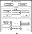
- FIG.2A shows a detailed block diagram of a path generating system for generating a safe navigation path for navigating a driverless vehicle in accordance with some embodiments of the present disclosure.
- the path generating system 107 may include data 203 and modules 205 .
- the data 203 is stored in the memory 113 configured in the path generating system 107 as shown in the FIG.2A .
- the data 203 may include path data 207 , environmental data 209 , vehicle parameters and characteristics data 211 , navigation points data 213 and other data 219 .
- modules 205 are described herein in detail.
- the data 203 may be stored in the memory 113 in form of various data structures. Additionally, the data 203 can be organized using data models, such as relational or hierarchical data models.
- the other data 219 may be store data, including temporary data and temporary files, generated by the modules 205 for performing the various functions of the path generating system 107 .
- the data 203 stored in the memory 113 may be processed by the modules 205 of the path generating system 107 .
- the modules 205 may be stored within the memory 113 .
- the modules 205 communicatively coupled to a processor 109 configured in the path generating system 107 may also be present outside the memory 113 as shown in FIG.2A and implemented as hardware.
- the term modules refer to an application specific integrated circuit (ASIC), an electronic circuit, a processor (shared, dedicated, or group) and memory that execute one or more software or firmware programs, a combinational logic circuit, and/or other suitable components that provide the described functionality.
- ASIC application specific integrated circuit
- processor shared, dedicated, or group
- memory that execute one or more software or firmware programs, a combinational logic circuit, and/or other suitable components that provide the described functionality.
- the modules 205 may include, for example, a vehicle parameter recording/replacing module 223 , a receiving module 225 , a virtual ray tracing module 227 , a navigating module 228 , a realigning module 229 , a retracting module 231 , a linking module 232 and other modules 241.
- the other modules 241 may be used to perform various miscellaneous functionalities of the path generating system 107 . It will be appreciated that such aforementioned modules 205 may be represented as a single module or a combination of different modules.
- the vehicle parameter recording/replacing module 223 may record values associated with one or more vehicle parameters and values associated with one or more vehicle capability characteristics when a driverless vehicle 106 is initiated.
- the one or more vehicle capability characteristics may include, but not limited to, possible rate of change of steering angle at different speeds, turning radius, static inertia and dynamic inertia of the driverless vehicle 106 .
- the vehicle parameters may include, but not limited to, dimensions, mass and wheel friction of the driverless vehicle 106 .
- the values associated with one or more vehicle parameters and values associated with one or more vehicle capability characteristics may be stored as the vehicle parameters and characteristics data 211 .
- the values associated with the one or more vehicle capability characteristics and the one or more vehicle parameters may be pre-recorded and stored in the memory 113 .
- the vehicle parameter recording/replacing module 223 may record new set of values associated with the one or more vehicle capability characteristics and the one or more vehicle parameters when the driverless vehicle 106 is initiated. Further, the vehicle parameter recording/replacing module 223 may compare the recorded new set of values with the pre-recorded values to detect deviation in the pre-recorded values and the newly recorded values. The vehicle parameter recording/replacing module 223 may replace the pre-recorded values with the newly recorded values when the deviation is detected.
- the vehicle parameter recording/replacing module 223 may retain the pre-recorded values.
- the one or more vehicle parameters and the one or more vehicle capability characteristics whose values should be recorded at initiation may be pre-configured.
- the one or more vehicle parameters and the one or more vehicle capability characteristics may assist in determining location and direction of the driverless vehicle 106 in real-time.
- the receiving module 225 may receive one or more pre-generated paths between a source point and a destination point in real-time from one or more sources 103 .
- the one or more sources 103 may be a navigation application, application related to maps, an image capturing device, a terrain detection system, a database and the like.
- the one or more pre-generated paths may be stored as the path data 207 .
- the source point and the destination point may be pre-configured by a user associated with the path generating system 107 .
- the receiving module 225 may receive an environmental data 209 corresponding to each of the one or more pre-generated paths from the one or more sources 103 in real-time.
- the environmental data 209 may include, but not limited to, data related to terrain associated with each of the one or more pre-generated paths and one or more obstacles associated with each of the one or more pre-generated paths.
- the one or more obstacles may be any items that hinder movement of a driverless vehicle.
- the one or more obstacles may be a deviation barrier, a rock, a branch of a tree fallen on a road, vehicles on the road, workers working on the road, animals and the like.
- the receiving module 225 may receive the one or more pre-generated paths and the environmental data 209 corresponding to each of the one or more pre-generated paths at pre-configured time intervals.
- the pre-configured time intervals may be 300 milli seconds (ms), 250ms and the like.
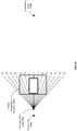
- the virtual ray tracing module 227 may trace virtual rays to detect possibility of the driverless vehicle 106 hitting the one or more obstacles. Initially, the virtual ray tracing module 227 may select one or more originating points along each of the one or more pre-generated paths. In some embodiments, the one or more originating points may be selected one at a time. The virtual ray tracing mechanism is explained below with respect to one originating point and one pre-generated path at a given point of time. In some embodiments, the virtual ray tracing module 227 may trace virtual rays from the originating point in a preconfigured angle range up to a preconfigured distance along the pre-generated path as shown in the FIG.2B .
- the virtual ray tracing module 227 may create a virtual rectangular boundary 233d around the driverless vehicle 106 based on the one or more vehicle parameters such as the dimensions of the driverless vehicle 106 .
- One edge of the virtual rectangular boundary 233d may align with the end points of the virtual rays as shown in the FIG.2B .
- the virtual ray tracing module 227 may check if the virtual rays are hitting the one or more obstacles i.e. whether the imaginary rectangular boundary is touching the one or more obstacles.
- the virtual ray tracing module 227 may check if the driverless vehicle 106 is capable of proceeding forward along direction of the virtual rays based on the one or more vehicle parameters, the one or more vehicle capability characteristics and the terrain condition of the environment data 209 . As an example, if the terrain condition is rocky and if the driverless vehicle 106 is not built well to move in the rocky terrain condition then the virtual ray tracing module 227 may activate the realigning module 229 or the retracting module 231 dynamically as per requirement. If the driverless vehicle 106 is capable of proceeding forward along the direction of the virtual rays, the virtual ray tracing module 227 may identify the originating point as a navigation point.
- the one or more pre-generated paths may be considered as a base path/ a guide while selecting the navigation points.
- the navigation point may be stored as the navigation points data 213 .
- the navigating module 228 may navigate the driverless vehicle 106 up to a certain forward distance.
- the certain forward distance may be the distance between the navigation point and a subsequent originating point.
- the forward distance is either a pre-configured forward distance or a dynamically generated forward distance.
- subsequent originating points are selected for tracing the virtual rays and also subsequent navigation points may be obtained.
- the virtual ray tracing module 227 may activate the realigning module 229 or the retracting module 231 as per requirement.
- the realigning module 229 may be activated when the one or more obstacles are present at a preconfigured angle of the traced virtual rays and in a corresponding preconfigured alignment distance range from the originating point, wherein the corresponding preconfigured alignment distance range is selected for each of the preconfigured angle based on one or more vehicle parameters and one or more vehicle capability characteristics.
- the preconfigured angle lies within the preconfigured angle range.
- the preconfigured angle range shown in the FIG.2B is -35 to +35.
- the driverless vehicle 106 is represented within the virtual rectangular boundary 233d.
- the preconfigured alignment distance range is the distance starting from the originating point that lies within the preconfigured distance up to the end of the virtual rectangular boundary 233d, which varies with the preconfigured angle of each virtual ray.
- the lower virtual rectangular boundary 233d is not allowed to hit the one or more obstacles at any point of ray-tracing process.
- the preconfigured alignment distance range may be from Ometre to 3.5metre for the virtual ray at the preconfigured angle of -25degree. Consider the one or more obstacles are present at the virtual ray of the preconfigured angle -25degree.
- the one or more obstacles may not be a threat to the driverless vehicle 106 and the originating point may be considered as the navigation point. Further, the driverless vehicle 106 moves forward for the certain pre-configured forward distance without any re-alignment of the position of the traced virtual rays.
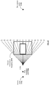
- the realigning module 229 may realign position of the traced virtual rays from the originating point in different angles as shown in the FIG.2C .
- realigning the position of the traced virtual rays may be performed with one different angle at a time until a realigning condition is satisfied.
- the realigning condition to be satisfied may be escaping the one or more obstacles.
- the realigning condition to be satisfied may be detecting the position of the virtual ray that does not hit the one or more obstacles and along the direction of which the driverless vehicle 106 is capable of proceeding forward.
- the different angles are either preconfigured or dynamically generated based on the one or more vehicle parameters and the one or more vehicle capability characteristics.
- the realigning module 229 may check the realigning condition. If the realigning module 229 detects that the realigning condition is satisfied, the originating point may be identified as the navigation point and the navigating module 228 may navigate the driverless vehicle 106 up to the certain forward distance. If the realigning module 229 detects that the realigning condition is not satisfied for any of the different angles, the retracting module 231 may be activated.
- the retracting module 231 may retract from the originating point and select an alternative originating point when the virtual ray tracing module 227 and the realigning module 229 fail to identify the one or more navigation points from the originating point.
- retraction of the driverless vehicle 106 may include retracting from the originating point to a previous navigation point.
- retraction of the driverless vehicle 106 may include discarding one or more previous navigation points.
- the retracting module 231 may decide on number of the one or more navigation points to be discarded based on the one or more vehicle parameters and the one or more vehicle capability characteristics.
- an alternative originating point may be selected for tracing the virtual rays.
- the linking module 232 may link the one or more navigation points based on one or more predefined techniques to generate a safe navigation path for navigating the driverless vehicle 106 .
- the one or more predefined techniques may be a curve fitting technique.
- linking of the one or more navigation points may include generating interpolated points between consecutive navigation points.
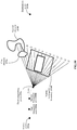
- FIG.2D - FIG.2G where the method of tracing the virtual rays to generate the safe navigation path is illustrated.
- point 233a indicates a source point and point 233b indicates the destination point.
- point 235a may be selected as the originating point.
- the virtual ray tracing module 227 may trace the virtual rays in an angle range of +35 to -35 degree and up to a distance of 5 metre from the first originating point 235a. End points of the traced virtual rays may be aligned with a virtual rectangular boundary 233d.
- the virtual ray tracing module 227 may check if any of the traced virtual rays beyond its corresponding preconfigured alignment distance range hits the one or more obstacles.
- the virtual ray tracing module 227 may detect that the traced virtual rays do not hit the one or more obstacles.
- the virtual ray tracing module 227 may check if the driverless vehicle 106 is capable of proceeding forward along direction of the virtual rays based on the one or more vehicle parameters, the one or more vehicle capability characteristics and the terrain condition of the environment data 209 .
- the terrain condition in which the driverless vehicle 106 is moving is a highway.
- the virtual ray tracing module 227 may detect that the driverless vehicle 106 is capable of proceeding forward on the highway based on the one or more vehicle parameters and the one or more vehicle capability characteristics such as wheel friction, mass of the driverless vehicle 106 and the like. Therefore, the virtual ray tracing module 227 identifies the first originating point 235a as a navigation point 236a (as shown in the FIG.2E ).
- the navigating module 228 may navigate the driverless vehicle 106 to a certain pre-configured forward distance, for example 0.5metre as shown in the FIG.2E . Meanwhile, a new pre-generated path is received along with new environment data 209 which is dynamically updated in the path generating system 107 . Upon moving forward, point 235b is selected as the second originating point as shown in the FIG.2F .
- the virtual ray tracing module 227 may trace the virtual rays in an angle range of +35 to -35 degree and up to a distance of 5 metre from the second originating point 235b. End points of the traced virtual rays may be aligned with a virtual rectangular boundary 233d . The virtual ray tracing module 227 may check if any of the traced virtual rays beyond its corresponding preconfigured alignment distance range hits the one or more obstacles. The virtual ray tracing module 227 may detect a first obstacle 233e at a virtual ray of preconfigured angle -10degree and at a distance of 3.5metre from the second originating point 235b .
- the realigning module 229 may realign position of the traced virtual rays to escape the first obstacle 233e.
- the angle for realigning the position of the traced virtual rays is selected based on the one or more vehicle parameters and the one or more vehicle capability characteristics.
- the dimensions of the driverless vehicle 106 may be length "X" metre, width "Y” metre and height “Z” metre.
- the wheel friction may be "F” units and the possible rate of change of steering angle is "R” units.
- the realigning module 229 may select the angle for realigning as "+1 1degree” and realigns the position of the traced virtual rays by +11degree as shown in the FIG.2G .
- the first obstacle 233e may be present at a new preconfigured angle.
- the realigning module 229 checks if the first obstacle 233e still lies within a new preconfigured alignment distance range corresponding to the new preconfigured angle.
- the virtual ray tracing module 227 may check if the driverless vehicle 106 is capable of proceeding forward along direction of the virtual rays based on the one or more vehicle parameters, the one or more vehicle capability characteristics and the terrain condition of the environment data 209 . Since the terrain condition in which the driverless vehicle 106 is moving is a highway and the driverless vehicle 106 is capable of proceeding forward on the highway the virtual ray tracing module 227 identifies the second originating point 235b as a subsequent navigation point i.e. second navigation point 236b (as shown in the FIG.2H ).
- the navigating module 228 may navigate the driverless vehicle 106 to the certain pre-configured forward distance of 0.5metre. Meanwhile, a new pre-generated path is received along with new environment data 209 which is dynamically updated in the path generating system 107 . Upon moving forward, point 235c is selected as a third originating point 235c in the new pre-generated path as shown in FIG.2H .
- the virtual ray tracing module 227 may check if the driverless vehicle 106 is capable of proceeding forward along direction of the virtual rays based on the one or more vehicle parameters, the one or more vehicle capability characteristics and the terrain condition of the environment data 209 .
- the virtual ray tracing module 227 identifies the third originating point 235c as a subsequent navigation point i.e. third navigation point 236c and the driverless vehicle 106 moves forward. Further, in a scenario where upon following the virtual ray tracing procedure and the realigning procedure for the third originating point 235c , if the driverless vehicle 106 could not escape a next obstacle, the retracting module 231 may be activated. The retracting module 231 may retract to the previous navigation point or further behind based on severity of the blockage and repeat the virtual ray tracing procedure and the realigning procedure until the next obstacle is escaped and a new navigation point is obtained.
- the one or more navigation points are linked by the linking module 232 to obtain the safe navigation path.
- the safe navigation path is a path that enables the vehicle escape obstacles and experience minimum number of jerks or no jerks, uniform speed and good pick up.
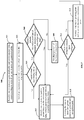
- FIG.3 shows a flowchart illustrating a method of generating a safe navigation path for navigating a driverless vehicle in accordance with some embodiments of the present disclosure.
- the method 300 includes one or more blocks illustrating a method of generating a safe navigation path for navigating a driverless vehicle 106 .
- the method 300 may be described in the general context of computer executable instructions.
- computer executable instructions can include routines, programs, objects, components, data structures, procedures, modules, and functions, which perform functions or implement abstract data types.
- the order in which the method 300 is described is not intended to be construed as a limitation, and any number of the described method blocks can be combined in any order to implement the method 300 . Additionally, individual blocks may be deleted from the methods without departing from the scope of the subject matter described herein. Furthermore, the method 300 can be implemented in any suitable hardware, software, firmware, or combination thereof.
- the method 300 may include receiving, by a processor 109 of the path generating system 107 , one or more pre-generated paths between a source point and a destination point and an environmental data 209 corresponding to each of the one or more pre-generated map paths from one or more sources in real-time.
- the source point and the destination point may be provided by a user associated with the path generating system 107 .
- the method 300 may include selecting, by the processor 109 , one or more originating points along each of the one or more pre-generated paths.
- the processor 109 may trace the virtual rays in a preconfigured angle range up to a preconfigured distance from each of one or more originating points along each of the one or more pre-generated paths.
- the processor 109 may check for a condition if the traced virtual rays are hitting one or more obstacles. If the traced virtual rays are not hitting the one or more obstacles, the method 300 may proceed to block 307 via "No". If the traced virtual rays are hitting one or more obstacles, the method 300 may proceed to condition block 308 via "Yes".
- the method 300 may include, identifying, by the processor 109 , one or more navigation points from each of the one or more originating points based on the environmental data 209 , one or more vehicle capability characteristics and one or more vehicle parameters.
- the processor 109 may record values associated with the one or more vehicle parameters and the vehicle capability characteristics when the driverless vehicle 106 is initiated.
- the method 300 may include, checking for a condition if the one or more obstacles are present beyond a preconfigured alignment distance range for a corresponding preconfigured angle of the virtual ray.
- the preconfigured alignment distance range is selected based on the one or more vehicle parameters and the one or more vehicle capability characteristics.
- the preconfigured angle is within the preconfigured angle range and the preconfigured alignment distance range is within the preconfigured distance. If the one or more obstacles are present beyond the preconfigured alignment distance range, the method 300 proceeds to block 307 via "Yes”. If the one or more obstacles are not present beyond the preconfigured alignment distance range, the method 300 proceeds to block 309 via "No".
- the method 300 may include, realigning, by the processor 109, position of the virtual rays from the originating point in different angles.
- the method 300 may include checking for a condition if the driverless vehicle 106 could escape the one or more obstacles upon realigning. If the driverless vehicle 106 escapes the one or more obstacles upon realigning, the method 300 proceeds to block 307 . If the driverless vehicle 106 does not escape the one or more obstacles upon realigning, the method 300 proceeds to block 313 .
- the method 300 may include, retracting, by the processor 109 , from the originating point and select an alternative originating point for tracing the virtual rays and revert to block 303 .
- the method 300 may include, linking, by the processor 109 , the one or more navigation points based on one or more predefined techniques to generate the safe navigation path for navigating the driverless vehicle 106 .
- linking the one or more navigation points may include generating interpolated points between consecutive navigation points.
- FIG.4 is a block diagram of an exemplary vehicle computer system for implementing embodiments consistent with the present disclosure.
- FIG.4 illustrates a block diagram of an exemplary vehicle computer system 400 for implementing embodiments consistent with the present invention.
- the vehicle computer system 400 can be path generating system 107 that is used for generating a safe navigation path for navigating a driverless vehicle 106.
- the vehicle computer system 400 may include a central processing unit (“CPU” or "processor") 402.
- the processor 402 may include at least one data processor for executing program components for executing user or system-generated business processes.
- a user may include a person, a person using a device such as such as those included in this invention, or such a device itself.
- the processor 402 may include specialized processing units such as integrated system (bus) controllers, memory management control units, floating point units, graphics processing units, digital signal processing units, etc.
- the processor 402 may be disposed in communication with one or more input/output (I/O) devices (411 and 412) via I/O interface 401.
- the I/O interface 401 may employ communication protocols/methods such as, without limitation, audio, analog, digital, stereo, IEEE-1394, serial bus, Universal Serial Bus (USB), infrared, PS/2, BNC, coaxial, component, composite, Digital Visual Interface (DVI), high-definition multimedia interface (HDMI), Radio Frequency (RF) antennas, S-Video, Video Graphics Array (VGA), IEEE 802.n /b/g/n/x, Bluetooth, cellular (e.g., Code-Division Multiple Access (CDMA), High-Speed Packet Access (HSPA+), Global System For Mobile Communications (GSM), Long-Term Evolution (LTE), WiMax, or the like), etc.
- CDMA Code-Division Multiple Access
- HSPA+ High-Speed Packet Access
- GSM Global System For Mobile Communications
- LTE Long-Term Evolution
- the vehicle computer system 400 may communicate with one or more I/O devices (411 and 412).
- the processor 402 may be disposed in communication with a communication network 409 via a network interface 403.
- the network interface 403 may communicate with the communication network 409.
- the network interface 403 may employ connection protocols including, without limitation, direct connect, Ethernet (e.g., twisted pair 10/100/1000 Base T), Transmission Control Protocol/Internet Protocol (TCP/IP), token ring, IEEE 802.11 a/b/g/n/x, etc.
- TCP/IP Transmission Control Protocol/Internet Protocol
- IEEE 802.11 a/b/g/n/x etc.
- the vehicle computer system 400 may communicate with a with one or more sources 410 (410 a up to 410 n ).
- the communication network 409 can be implemented as one of the different types of networks, such as intranet or Local Area Network (LAN) and such within the organization.
- LAN Local Area Network
- the communication network 409 may either be a dedicated network or a shared network, which represents an association of the different types of networks that use a variety of protocols, for example, Hypertext Transfer Protocol (HTTP), Transmission Control Protocol/Internet Protocol (TCP/IP), Wireless Application Protocol (WAP), etc., to communicate with each other. Further, the communication network 409 may include a variety of network devices, including routers, bridges, servers, computing devices, storage devices, etc.
- the one or more sources 410 may include, but not limited to, a navigation application, application related to maps, an image capturing device, a terrain detection system and a database.
- the processor 402 may be disposed in communication with a memory 405 (e.g., RAM, ROM, etc.
- the storage interface 404 may connect to memory 405 including, without limitation, memory drives, removable disc drives, etc., employing connection protocols such as Serial Advanced Technology Attachment (SATA), Integrated Drive Electronics (IDE), IEEE-1394, Universal Serial Bus (USB), fibre channel, Small Computer Systems Interface (SCSI), etc.
- the memory drives may further include a drum, magnetic disc drive, magneto-optical drive, optical drive, Redundant Array of Independent Discs (RAID), solid-state memory devices, solid-state drives, etc.
- the memory 405 may store a collection of program or database components, including, without limitation, a user interface 406, an operating system 407 , a web browser 408 etc.
- the vehicle computer system 400 may store user/application data, such as the data, variables, records, etc. as described in this invention.
- databases may be implemented as fault-tolerant, relational, scalable, secure databases such as Oracle or Sybase.
- the operating system 407 may facilitate resource management and operation of the vehicle computer system 400 .
- Examples of operating systems include, without limitation, Apple Macintosh OS X, UNIX, Unix-like system distributions (e.g., Berkeley Software Distribution (BSD), FreeBSD, NetBSD, OpenBSD, etc.), Linux distributions (e.g., Red Hat, Ubuntu, Kubuntu, etc.), International Business Machines (IBM) OS/2, Microsoft Windows (XP, Vista/7/8, etc.), Apple iOS, Google Android, Blackberry Operating System (OS), or the like.
- the User interface 406 may facilitate display, execution, interaction, manipulation, or operation of program components through textual or graphical facilities.
- GUIs may provide computer interaction interface elements on a display system operatively connected to the vehicle computer system 400 , such as cursors, icons, check boxes, menus, scrollers, windows, widgets, etc.
- Graphical User Interfaces may be employed, including, without limitation, Apple Macintosh operating systems' Aqua, IBM OS/2, Microsoft Windows (e.g., Aero, Metro, etc.), Unix X-Windows, web interface libraries (e.g., ActiveX, Java, Javascript, AJAX, HTML, Adobe Flash, etc.), or the like.
- the vehicle computer system 400 may implement the web browser 408 stored program components.
- the web browser 408 may be a hypertext viewing application, such as Microsoft Internet Explorer, Google Chrome, Mozilla Firefox, Apple Safari, etc. Secure web browsing may be provided using Secure Hypertext Transfer Protocol (HTTPS) secure sockets layer (SSL), Transport Layer Security (TLS), etc. Web browsers may utilize facilities such as AJAX, DHTML, Adobe Flash, JavaScript, Java, Application Programming Interfaces (APIs), etc.
- the vehicle computer system 400 may implement a mail server stored program component.
- the mail server may be an Internet mail server such as Microsoft Exchange, or the like.
- the mail server may utilize facilities such as Active Server Pages (ASP), ActiveX, American National Standards Institute (ANSI) C++/C#, Microsoft .NET, CGI scripts, Java, JavaScript, PERL, PHP, Python, WebObjects, etc.
- the mail server may utilize communication protocols such as Internet Message Access Protocol (IMAP), Messaging Application Programming Interface (MAPI), Microsoft Exchange, Post Office Protocol (POP), Simple Mail Transfer Protocol (SMTP), or the like.
- the vehicle computer system 400 may implement a mail client stored program component.
- the mail client may be a mail viewing application, such as Apple Mail, Microsoft Entourage, Microsoft Outlook, Mozilla Thunderbird, etc.
- a computer-readable storage medium refers to any type of physical memory on which information or data readable by a processor may be stored.
- a computer-readable storage medium may store instructions for execution by one or more processors, including instructions for causing the processor(s) to perform steps or stages consistent with the embodiments described herein.
- the term "computer-readable medium” should be understood to include tangible items and exclude carrier waves and transient signals, i.e., non-transitory. Examples include Random Access Memory (RAM), Read-Only Memory (ROM), volatile memory, non-volatile memory, hard drives, Compact Disc (CD) ROMs, Digital Video Disc (DVDs), flash drives, disks, and any other known physical storage media.
- the present disclosure provides a method and a system for generating a safe navigation path for navigating a driverless vehicle.
- the present disclosure provides a feature wherein the safe navigation path is generated considering vehicle parameters and vehicle capability characteristics such as a possible rate of change of steering angle at various speeds, turning radius, static inertia, dynamic inertia of the driverless vehicle and the like.
- the present disclosure provides a feature wherein the safe navigation path is generated without the usage of any sensor configured in the autonomous vehicle/driverless vehicle.
Landscapes
- Engineering & Computer Science (AREA)
- Radar, Positioning & Navigation (AREA)
- Remote Sensing (AREA)
- Physics & Mathematics (AREA)
- Automation & Control Theory (AREA)
- General Physics & Mathematics (AREA)
- Aviation & Aerospace Engineering (AREA)
- Electromagnetism (AREA)
- Mechanical Engineering (AREA)
- Transportation (AREA)
- Human Computer Interaction (AREA)
- Navigation (AREA)
- Traffic Control Systems (AREA)
- Control Of Driving Devices And Active Controlling Of Vehicle (AREA)
Abstract
Description
- The present subject matter relates generally to the field of automobile engineering, and more particularly, but not exclusively, to a method and a system for generating a safe navigation path for navigating a driverless vehicle.
- Nowadays, navigating autonomous vehicle (AV)/driverless vehicle is becoming an important requirement in different application areas. AVs are the vehicles that are capable of sensing the environment around them for moving on the road without any human intervention. The AV senses the environment with the help of sensors configured in the AV, such as Laser, Light Detection and Ranging (LIDAR), Global Positioning System (GPS), computer vision and the like. A control system associated with the AV may receive inputs from the sensors, based on which the control system may identify appropriate navigation path, obstacles in the dynamically changing environment and the like.
- Generally, identifying the navigation path for the AV may include a combination of three basic abilities such as localization, path planning and vehicle control. Localization determines the ability of the AV to calculate its current position and orientation within a global reference frame. Path planning determines a path and a sequence of command velocity to reach a desired destination from the current position of the AV. The planned path may be followed by the AV using a feedback controller system which includes dynamic obstacle avoidance as well as global path pre-planning and/or re-planning.
- Existing techniques for navigating the AV include classical planning, case based planning, coordinated robot planning and the like. However, for path planning, existing techniques only focus on either collision avoidance or shortest path between a source point and a destination point as a primary criterion. However, currently, there exists no mechanism to check whether the detected shortest path for navigating the driverless vehicle is a safe path or not. Further, the existing techniques use numerous sensors to navigate the AV that makes the overall system complex.
- One or more shortcomings of the prior art may be overcome and additional advantages may be provided through the present disclosure. Additional features and advantages may be realized through the techniques of the present disclosure. Other embodiments and aspects of the disclosure are described in detail herein and are considered a part of the claimed disclosure.
- Disclosed herein is a method of generating a safe navigation path for navigating a driverless vehicle. The method comprises receiving, by a path generating system, one or more pre-generated paths between a source point and a destination point and an environmental data corresponding to each of the one or more pre-generated paths from one or more sources in real-time. Further, the path generating system identifies one or more navigation points in real-time based on the environmental data, one or more vehicle capability characteristics and one or more vehicle parameters by tracing virtual rays in a preconfigured angle range up to a preconfigured distance from each of one or more originating points along each of the one or more pre-generated paths. Finally, the path generating system links the one or more navigation points based on one or more predefined techniques to generate the appropriate navigation path for navigating the driverless vehicle.
- Further, the present disclosure includes a path generating system for generating a safe navigation path for navigating a driverless vehicle. The path generating system comprises a processor and a memory communicatively coupled to the processor. The memory stores the processor-executable instructions, which, on execution, causes the processor to receive one or more pre-generated paths between a source point and a destination point and an environmental data corresponding to each of the one or more pre-generated paths from one or more sources. Further, the processor identifies one or more navigation points in real-time based on the environmental data, one or more vehicle capability characteristics and one or more vehicle parameters by tracing virtual rays in a preconfigured angle range up to a preconfigured distance from each of one or more originating points along each of the one or more pre-generated paths. Finally, the processor connects the one or more navigation points based on one or more predefined techniques to generate the appropriate navigation path for navigating the driverless vehicle.
- Furthermore, the present disclosure comprises a non-transitory computer readable medium including instructions stored thereon that when processed by at least one processor causes a path generating system to perform operations comprising receiving one or more pre-generated paths between a source point and a destination point and an environmental data corresponding to each of the one or more pre-generated paths from one or more sources in real-time. Further, the instructions cause the processor to identify one or more navigation points in real-time based on the environmental data and one or more vehicle capability characteristics and one or more vehicle parameters by tracing virtual rays in a preconfigured angle range up to a preconfigured distance from each of one or more originating points along each of the one or more pre-generated paths. Finally, the instructions cause the processor to link the one or more navigation points based on one or more predefined techniques to generate the safe navigation path for navigating the driverless vehicle.
- The foregoing summary is illustrative only and is not intended to be in any way limiting. In addition to the illustrative aspects, embodiments, and features described above, further aspects, embodiments, and features will become apparent by reference to the drawings and the following detailed description.
- The accompanying drawings, which are incorporated in and constitute a part of this disclosure, illustrate exemplary embodiments and, together with the description, serve to explain the disclosed principles. In the figures, the left-most digit(s) of a reference number identifies the figure in which the reference number first appears. The same numbers are used throughout the figures to reference like features and components. Some embodiments of system and/or methods in accordance with embodiments of the present subject matter are now described, by way of example only, and with reference to the accompanying figures, in which:
-
FIG.1 shows an exemplary architecture for generating a safe navigation path for navigating a driverless vehicle in accordance with some embodiments of the present disclosure; -
FIG.2A shows a detailed block diagram of a path generating system for generating a safe navigation path for navigating a driverless vehicle in accordance with some embodiments of the present disclosure; -
FIG.2B - FIG.2C shows an exemplary illustration of tracing virtual rays along with a virtual rectangular boundary in accordance with some embodiments of the present disclosure; -
FIG.2D - FIG.2H shows an exemplary illustration for generating navigation points in accordance with some embodiments of the present disclosure; -
FIG.3 shows a flowchart illustrating a method of generating a safe navigation path for navigating a driverless vehicle in accordance with some embodiments of the present disclosure; and -
FIG.4 is a block diagram of an exemplary vehicle computer system for implementing embodiments consistent with the present disclosure. - It should be appreciated by those skilled in the art that any block diagrams herein represent conceptual views of illustrative systems embodying the principles of the present subject matter. Similarly, it will be appreciated that any flow charts, flow diagrams, state transition diagrams, pseudo code, and the like represent various processes which may be substantially represented in computer readable medium and executed by a computer or processor, whether or not such computer or processor is explicitly shown.
- In the present document, the word "exemplary" is used herein to mean "serving as an example, instance, or illustration." Any embodiment or implementation of the present subject matter described herein as "exemplary" is not necessarily to be construed as preferred or advantageous over other embodiments.
- While the disclosure is susceptible to various modifications and alternative forms, specific embodiment thereof has been shown by way of example in the drawings and will be described in detail below. It should be understood, however that it is not intended to limit the disclosure to the forms disclosed, but on the contrary, the disclosure is to cover all modifications, equivalents, and alternative falling within the scope of the disclosure.
- The terms "comprises", "comprising", "includes" or any other variations thereof, are intended to cover a non-exclusive inclusion, such that a setup, device or method that includes a list of components or steps does not include only those components or steps but may include other components or steps not expressly listed or inherent to such setup or device or method. In other words, one or more elements in a system or apparatus proceeded by "comprises... a" does not, without more constraints, preclude the existence of other elements or additional elements in the system or method.
- Disclosed herein are a method and a path generating system for generating a safe navigation path for navigating a driverless vehicle. The present disclosure provides a feature wherein the safe navigation path is generated considering vehicle parameters such as possible rate of change of steering angle at various speeds, turning radius, static inertia or dynamic inertia of the driverless vehicle and the like. Initially the path generating system may receive one or more pre-generated paths between a source point and a destination point and an environmental data corresponding to each of the one or more pre-generated paths from one or more sources. As an example, the one or more sources may be a navigation application, application related to maps, an image capturing device, a database and the like. The environmental data may include data related to terrain associated with each of the one or more pre-generated paths and one or more obstacles associated with each of the one or more pre-generated paths. As an example, the one or more obstacles may be a speed breaker, a rock, a branch of a tree fallen on the road, vehicles on the road, workers working on the road and the like. Upon obtaining the one or more pre-generated paths and the environmental data corresponding to each of the one or more pre-generated paths, the path generating system may select an originating point on each of the one or more pre-generated paths. Upon selecting the originating point, the path generating system may trace virtual rays from the originating point in a preconfigured angle range up to a preconfigured distance along each of the one or more pre-generated paths.
- The path generating system may identify one or more navigation points in real-time based on the environmental data, one or more vehicle capability characteristics and one or more vehicle parameters when the virtual rays do not hit the one or more obstacles. Upon obtaining the navigation points from the originating point, the path generating system virtually moves the driverless vehicle forward for a certain distance and obtains one or more originating points for tracing the virtual rays until the destination point is reached. If the virtual rays hit the one or more obstacles, the path generating system may identify the one or more navigation points in real-time by realigning position of the traced virtual rays from the originating point in different angles until the traced virtual rays escape the one or more obstacles. The position of the traced virtual rays is realigned when the one or more obstacles are present at a preconfigured angle of the traced virtual rays and in a corresponding preconfigured alignment distance range from the originating point. The corresponding preconfigured alignment distance range is selected for each of the preconfigured angle based on one or more vehicle parameters and one or more vehicle capability characteristics. If the one or more obstacles occurring at a certain preconfigured angle are beyond the preconfigured alignment distance range corresponding to the preconfigured angle, the originating point may be considered as the navigation point and moves forward for the pre-configured forward distance without any re-alignment. The preconfigured angle is within the preconfigured angle range and the corresponding preconfigured alignment distance range is within the preconfigured distance.
- Further, when the path generating system is unable to identify the one or more navigation points from the originating point, the path generating system may retract from the originating point and select an alternative originating point. As an example, the retraction of the driverless vehicle may include retracting from current originating point to previous navigation point or discarding one or more previous navigation points. Finally, upon obtaining the one or more navigation points, the path generating system may link the one or more navigation points based on one or more predefined techniques to generate the safe navigation path for navigating the driverless vehicle. As an example, the one or more predefined techniques may be a curve fitting technique. In the present disclosure, the safe navigation path is generated without the use of any sensor configured in the driverless vehicle.
- In the following detailed description of the embodiments of the disclosure, reference is made to the accompanying drawings that form a part hereof, and in which are shown by way of illustration specific embodiments in which the disclosure may be practiced. These embodiments are described in sufficient detail to enable those skilled in the art to practice the disclosure, and it is to be understood that other embodiments may be utilized and that changes may be made without departing from the scope of the present disclosure. The following description is, therefore, not to be taken in a limiting sense.
-
FIG.1 shows an exemplary architecture for generating a safe navigation path for navigating a driverless vehicle in accordance with some embodiments of the present disclosure. - The
architecture 100 includes one or more sources,source 1 1031 to source n 103n (collectively referred to as one or more sources 103), adriverless vehicle 106 and apath generating system 107. As an example, the one or more sources 103 may be a navigation application, application related to maps, an image capturing device, a terrain detection system, a database and the like. The one or more sources 103 such as the navigation application and application related to maps provide one or more pre-generated paths between a source point and a destination point. As an example, the one or more pre-generated paths may be obtained using Dijkstra's algorithm, A-star algorithm and the like. In some embodiments, the source point and the destination point may be provided as inputs to thepath generating system 107 by a user associated with thepath generating system 107. Further, the one or more sources 103 such as the image capturing device, the terrain detection system and the database may provide environmental data. As an example, the environmental data may include, but not limited to, data related to terrain associated with each of the one or more pre-generated paths and one or more obstacles in each of the one or more pre-generated paths. In some embodiments, the one or more obstacles may be any items that hinder movement of a driverless vehicle. As an example, the one or more obstacles may be a deviation barrier, a rock, a branch of a tree fallen on a road, vehicles on the road, workers working on the road, animals and the like. The one or more sources 103 may be associated with thepath generating system 107 via a communication network (not shown inFIG.1 ). As an example, the communication network may be a wired communication network or a wireless communication network. - In some embodiments, the
path generating system 107 may be configured within thedriverless vehicle 106. Thepath generating system 107 may include ap rocessor 109, an Input/ Output (I/O)interface 111 and amemory 113. The I/O interface 111 may receive the pre-generated map and the environmental data from the one or more sources 103. Upon receiving, the one or more pre-generated paths and the environmental data, theprocessor 109 may select one or more originating points along each of the one or more pre-generated paths starting from the source point. Upon selecting the one or more originating points, theprocessor 109 may trace virtual rays from each of the one or more originating points in a preconfigured angle range up to a preconfigured distance along the pre-generated map. Theprocessor 109 may identify one or more navigation points from each of the one or more originating points based on the environmental data, one or more vehicle capability characteristics and one or more vehicle parameters when the virtual rays do not hit the one or more obstacles. As an example, the one or more vehicle capability characteristics may include, but not limited to, possible rate of change of steering angle at various speeds, turning radius, static inertia and dynamic inertia of thedriverless vehicle 106. As an example, the vehicle parameters may include, but not limited to, dimensions, mass and wheel friction of thedriverless vehicle 106. The vehicle capability characteristics and vehicle properties may be collectively described as vehicle properties. The term vehicle properties may refer to any parameter, characteristic or property of a vehicle that determines or otherwise influences the navigation path that the vehicle can safely follow. Thus, thepath generating system 107 may identify one or more navigation points in real-time based on environmental data and one or more vehicle properties. - In some embodiments, values associated with the one or more vehicle capability characteristics and the one or more vehicle parameters may be pre-recorded and stored in the
memory 113. Theprocessor 109 may record new set of values associated with the one or more vehicle capability characteristics and the one or more vehicle parameters when thedriverless vehicle 106 is initiated. The recorded new set of values are compared with the predefined values to identify presence of any deviation in the pre-recorded values and the newly recorded values. If theprocessor 109 identifies the deviation, then the pre-recorded values are replaced with the newly recorded values. If theprocessor 109 identifies no deviation, then the pre-recorded values are retained. - When the virtual rays traced from each of the one or more originating points do not hit the one or more obstacles, the
processor 109 may identify each originating point as the navigation point in real-time. Upon obtaining the navigation points from each of the one or more originating points, theprocessor 109 may virtually move thedriverless vehicle 106 forward for a certain distance to obtain subsequent originating points. The certain distance may be either preconfigured forward distance or dynamically generated forward distance. In some embodiments, if the virtual rays traced from an originating point hit the one or more obstacles, theprocessor 109 may realign position of the virtual rays from the originating point in different angles until the virtual rays escape the one or more obstacles. The position of the traced virtual rays is realigned when the one or more obstacles are present at a preconfigured angle of the traced virtual rays and in a corresponding preconfigured alignment distance range from the originating point. The preconfigured angle is within the preconfigured angle range and the corresponding preconfigured alignment distance range is within the preconfigured distance. The corresponding preconfigured alignment distance range is selected for each of the preconfigured angle based on one or more vehicle parameters and one or more vehicle capability characteristics. If the one or more obstacles occurring at a certain preconfigured angle are beyond the preconfigured alignment distance range corresponding to the preconfigured angle, the originating point may be considered as the navigation point and moves forward for the preconfigured forward distance without any re-alignment. Further, when theprocessor 109 is unable to identify the one or more navigation points from the originating point, theprocessor 109 may virtually retract from the originating point. In some embodiments, retraction may include retracting from the originating point to previous navigation point. In some embodiments, retraction of thedriverless vehicle 106 may include discarding one or more previous navigation points and selecting an alternative originating point for tracing virtual rays. - Finally, upon obtaining the one or more navigation points, the
processor 109 may link the one or more navigation points based on one or more predefined techniques to generate a safe navigation path for navigating thedriverless vehicle 106. As an example, the one or more predefined techniques may be a curve fitting technique. -
FIG.2A shows a detailed block diagram of a path generating system for generating a safe navigation path for navigating a driverless vehicle in accordance with some embodiments of the present disclosure. - In some implementations, the
path generating system 107 may includedata 203 andmodules 205. As an example, thedata 203 is stored in thememory 113 configured in thepath generating system 107 as shown in theFIG.2A . In one embodiment, thedata 203 may includepath data 207,environmental data 209, vehicle parameters andcharacteristics data 211, navigation pointsdata 213 andother data 219. In the illustratedFIG.2A ,modules 205 are described herein in detail. - In some embodiments, the
data 203 may be stored in thememory 113 in form of various data structures. Additionally, thedata 203 can be organized using data models, such as relational or hierarchical data models. Theother data 219 may be store data, including temporary data and temporary files, generated by themodules 205 for performing the various functions of thepath generating system 107. - In some embodiments, the
data 203 stored in thememory 113 may be processed by themodules 205 of thepath generating system 107. Themodules 205 may be stored within thememory 113. In an example, themodules 205 communicatively coupled to aprocessor 109 configured in thepath generating system 107, may also be present outside thememory 113 as shown inFIG.2A and implemented as hardware. As used herein, the term modules refer to an application specific integrated circuit (ASIC), an electronic circuit, a processor (shared, dedicated, or group) and memory that execute one or more software or firmware programs, a combinational logic circuit, and/or other suitable components that provide the described functionality. - In an embodiment, the
modules 205 may include, for example, a vehicle parameter recording/replacingmodule 223, a receivingmodule 225, a virtualray tracing module 227, a navigatingmodule 228, arealigning module 229, aretracting module 231, a linkingmodule 232 andother modules 241. Theother modules 241 may be used to perform various miscellaneous functionalities of thepath generating system 107. It will be appreciated that suchaforementioned modules 205 may be represented as a single module or a combination of different modules. - In some embodiments, the vehicle parameter recording/replacing
module 223 may record values associated with one or more vehicle parameters and values associated with one or more vehicle capability characteristics when adriverless vehicle 106 is initiated. As an example, the one or more vehicle capability characteristics may include, but not limited to, possible rate of change of steering angle at different speeds, turning radius, static inertia and dynamic inertia of thedriverless vehicle 106. As an example, the vehicle parameters may include, but not limited to, dimensions, mass and wheel friction of thedriverless vehicle 106. The values associated with one or more vehicle parameters and values associated with one or more vehicle capability characteristics may be stored as the vehicle parameters andcharacteristics data 211. In some embodiments, the values associated with the one or more vehicle capability characteristics and the one or more vehicle parameters may be pre-recorded and stored in thememory 113. The vehicle parameter recording/replacingmodule 223 may record new set of values associated with the one or more vehicle capability characteristics and the one or more vehicle parameters when thedriverless vehicle 106 is initiated. Further, the vehicle parameter recording/replacingmodule 223 may compare the recorded new set of values with the pre-recorded values to detect deviation in the pre-recorded values and the newly recorded values. The vehicle parameter recording/replacingmodule 223 may replace the pre-recorded values with the newly recorded values when the deviation is detected. If the deviation is not detected, the vehicle parameter recording/replacingmodule 223 may retain the pre-recorded values. In some embodiments, the one or more vehicle parameters and the one or more vehicle capability characteristics whose values should be recorded at initiation may be pre-configured. - The one or more vehicle parameters and the one or more vehicle capability characteristics may assist in determining location and direction of the
driverless vehicle 106 in real-time. - In some embodiments, the receiving
module 225 may receive one or more pre-generated paths between a source point and a destination point in real-time from one or more sources 103. As an example, the one or more sources 103 may be a navigation application, application related to maps, an image capturing device, a terrain detection system, a database and the like. The one or more pre-generated paths may be stored as thepath data 207. In some embodiments, the source point and the destination point may be pre-configured by a user associated with thepath generating system 107. Further, the receivingmodule 225 may receive anenvironmental data 209 corresponding to each of the one or more pre-generated paths from the one or more sources 103 in real-time. In some embodiments, theenvironmental data 209 may include, but not limited to, data related to terrain associated with each of the one or more pre-generated paths and one or more obstacles associated with each of the one or more pre-generated paths. In some embodiments, the one or more obstacles may be any items that hinder movement of a driverless vehicle. As an example, the one or more obstacles may be a deviation barrier, a rock, a branch of a tree fallen on a road, vehicles on the road, workers working on the road, animals and the like. In some embodiments, the receivingmodule 225 may receive the one or more pre-generated paths and theenvironmental data 209 corresponding to each of the one or more pre-generated paths at pre-configured time intervals. As an example, the pre-configured time intervals may be 300 milli seconds (ms), 250ms and the like. - In some embodiments, the virtual
ray tracing module 227 may trace virtual rays to detect possibility of thedriverless vehicle 106 hitting the one or more obstacles. Initially, the virtualray tracing module 227 may select one or more originating points along each of the one or more pre-generated paths. In some embodiments, the one or more originating points may be selected one at a time. The virtual ray tracing mechanism is explained below with respect to one originating point and one pre-generated path at a given point of time. In some embodiments, the virtualray tracing module 227 may trace virtual rays from the originating point in a preconfigured angle range up to a preconfigured distance along the pre-generated path as shown in theFIG.2B . In some embodiments, the virtualray tracing module 227 may create a virtualrectangular boundary 233d around thedriverless vehicle 106 based on the one or more vehicle parameters such as the dimensions of thedriverless vehicle 106. One edge of the virtualrectangular boundary 233d may align with the end points of the virtual rays as shown in theFIG.2B . Upon tracing the virtual rays, the virtualray tracing module 227 may check if the virtual rays are hitting the one or more obstacles i.e. whether the imaginary rectangular boundary is touching the one or more obstacles. If the virtual rays are not hitting the one or more obstacles, the virtualray tracing module 227 may check if thedriverless vehicle 106 is capable of proceeding forward along direction of the virtual rays based on the one or more vehicle parameters, the one or more vehicle capability characteristics and the terrain condition of theenvironment data 209. As an example, if the terrain condition is rocky and if thedriverless vehicle 106 is not built well to move in the rocky terrain condition then the virtualray tracing module 227 may activate therealigning module 229 or theretracting module 231 dynamically as per requirement. If thedriverless vehicle 106 is capable of proceeding forward along the direction of the virtual rays, the virtualray tracing module 227 may identify the originating point as a navigation point. In some embodiments, the one or more pre-generated paths may be considered as a base path/ a guide while selecting the navigation points. The navigation point may be stored as the navigation pointsdata 213. In some embodiments, upon identifying the navigation point, the navigatingmodule 228 may navigate thedriverless vehicle 106 up to a certain forward distance. In some embodiments, the certain forward distance may be the distance between the navigation point and a subsequent originating point. In some embodiments, the forward distance is either a pre-configured forward distance or a dynamically generated forward distance. Upon moving via the certain forward distance, subsequent originating points are selected for tracing the virtual rays and also subsequent navigation points may be obtained. Further, if the virtual rays are detected to be hitting the one or more obstacles, the virtualray tracing module 227 may activate therealigning module 229 or theretracting module 231 as per requirement. - In some embodiments, the realigning
module 229 may be activated when the one or more obstacles are present at a preconfigured angle of the traced virtual rays and in a corresponding preconfigured alignment distance range from the originating point, wherein the corresponding preconfigured alignment distance range is selected for each of the preconfigured angle based on one or more vehicle parameters and one or more vehicle capability characteristics. The preconfigured angle lies within the preconfigured angle range. As an example, the preconfigured angle range shown in theFIG.2B is -35 to +35. In theFIG.2B , thedriverless vehicle 106 is represented within the virtualrectangular boundary 233d. Further, the preconfigured alignment distance range is the distance starting from the originating point that lies within the preconfigured distance up to the end of the virtualrectangular boundary 233d, which varies with the preconfigured angle of each virtual ray. The lower virtualrectangular boundary 233d is not allowed to hit the one or more obstacles at any point of ray-tracing process. As an example, the preconfigured alignment distance range may be from Ometre to 3.5metre for the virtual ray at the preconfigured angle of -25degree. Consider the one or more obstacles are present at the virtual ray of the preconfigured angle -25degree. If these one or more obstacles are present beyond the preconfigured alignment distance range of Ometre - 3.5metre, the one or more obstacles may not be a threat to thedriverless vehicle 106 and the originating point may be considered as the navigation point. Further, thedriverless vehicle 106 moves forward for the certain pre-configured forward distance without any re-alignment of the position of the traced virtual rays. - In some embodiments, the realigning
module 229 may realign position of the traced virtual rays from the originating point in different angles as shown in theFIG.2C . In some embodiments, realigning the position of the traced virtual rays may be performed with one different angle at a time until a realigning condition is satisfied. In some embodiments, the realigning condition to be satisfied may be escaping the one or more obstacles. In some embodiments, the realigning condition to be satisfied may be detecting the position of the virtual ray that does not hit the one or more obstacles and along the direction of which thedriverless vehicle 106 is capable of proceeding forward. Further, the different angles are either preconfigured or dynamically generated based on the one or more vehicle parameters and the one or more vehicle capability characteristics. Therefore, upon realigning the position of the traced virtual rays for each different angle, the realigningmodule 229 may check the realigning condition. If therealigning module 229 detects that the realigning condition is satisfied, the originating point may be identified as the navigation point and the navigatingmodule 228 may navigate thedriverless vehicle 106 up to the certain forward distance. If therealigning module 229 detects that the realigning condition is not satisfied for any of the different angles, the retractingmodule 231 may be activated. - In some embodiments, the retracting
module 231 may retract from the originating point and select an alternative originating point when the virtualray tracing module 227 and therealigning module 229 fail to identify the one or more navigation points from the originating point. In some embodiments, retraction of thedriverless vehicle 106 may include retracting from the originating point to a previous navigation point. In some embodiments, retraction of thedriverless vehicle 106 may include discarding one or more previous navigation points. Theretracting module 231 may decide on number of the one or more navigation points to be discarded based on the one or more vehicle parameters and the one or more vehicle capability characteristics. Upon retracting from the originating point, an alternative originating point may be selected for tracing the virtual rays. - The procedure explained in the above modules to identify the one or more navigation points is repeated for each of the one or more originating points in each of the one or more pre-generated paths until the destination point is reached.
- In some embodiments, the linking
module 232 may link the one or more navigation points based on one or more predefined techniques to generate a safe navigation path for navigating thedriverless vehicle 106. As an example, the one or more predefined techniques may be a curve fitting technique. In some embodiments, linking of the one or more navigation points may include generating interpolated points between consecutive navigation points. - Consider an exemplary scenario as shown in
FIG.2D - FIG.2G where the method of tracing the virtual rays to generate the safe navigation path is illustrated. - In
FIG.2D ,point 233a indicates a source point andpoint 233b indicates the destination point. Initially,point 235a may be selected as the originating point. The virtualray tracing module 227 may trace the virtual rays in an angle range of +35 to -35 degree and up to a distance of 5 metre from thefirst originating point 235a. End points of the traced virtual rays may be aligned with a virtualrectangular boundary 233d. The virtualray tracing module 227 may check if any of the traced virtual rays beyond its corresponding preconfigured alignment distance range hits the one or more obstacles. The virtualray tracing module 227 may detect that the traced virtual rays do not hit the one or more obstacles. Further, the virtualray tracing module 227 may check if thedriverless vehicle 106 is capable of proceeding forward along direction of the virtual rays based on the one or more vehicle parameters, the one or more vehicle capability characteristics and the terrain condition of theenvironment data 209. Consider that the terrain condition in which thedriverless vehicle 106 is moving is a highway. The virtualray tracing module 227 may detect that thedriverless vehicle 106 is capable of proceeding forward on the highway based on the one or more vehicle parameters and the one or more vehicle capability characteristics such as wheel friction, mass of thedriverless vehicle 106 and the like. Therefore, the virtualray tracing module 227 identifies thefirst originating point 235a as anavigation point 236a (as shown in theFIG.2E ). Upon identifying thenavigation point 236a, the navigatingmodule 228 may navigate thedriverless vehicle 106 to a certain pre-configured forward distance, for example 0.5metre as shown in theFIG.2E . Meanwhile, a new pre-generated path is received along withnew environment data 209 which is dynamically updated in thepath generating system 107. Upon moving forward,point 235b is selected as the second originating point as shown in theFIG.2F . - With reference to
FIG.2F , the virtualray tracing module 227 may trace the virtual rays in an angle range of +35 to -35 degree and up to a distance of 5 metre from thesecond originating point 235b. End points of the traced virtual rays may be aligned with a virtualrectangular boundary 233d. The virtualray tracing module 227 may check if any of the traced virtual rays beyond its corresponding preconfigured alignment distance range hits the one or more obstacles. The virtualray tracing module 227 may detect afirst obstacle 233e at a virtual ray of preconfigured angle -10degree and at a distance of 3.5metre from thesecond originating point 235b. Consider the preconfigured alignment distance range for the virtual ray at the preconfigured angle - 10degree is Ometre to 4.5metre. Thefirst obstacle 233e is well within the preconfigured alignment distance range of Ometre to 4.5 metre. Therefore, the realigningmodule 229 may realign position of the traced virtual rays to escape thefirst obstacle 233e. The angle for realigning the position of the traced virtual rays is selected based on the one or more vehicle parameters and the one or more vehicle capability characteristics. Consider the dimensions of thedriverless vehicle 106 may be length "X" metre, width "Y" metre and height "Z" metre. Further, the wheel friction may be "F" units and the possible rate of change of steering angle is "R" units. Based on one or more vehicle parameters and the one or more vehicle capability characteristics, the realigningmodule 229 may select the angle for realigning as "+1 1degree" and realigns the position of the traced virtual rays by +11degree as shown in theFIG.2G . Upon realigning, thefirst obstacle 233e may be present at a new preconfigured angle. Therealigning module 229 checks if thefirst obstacle 233e still lies within a new preconfigured alignment distance range corresponding to the new preconfigured angle. Considering thefirst obstacle 233e lies beyond the new preconfigured alignment distance range, the virtualray tracing module 227 may check if thedriverless vehicle 106 is capable of proceeding forward along direction of the virtual rays based on the one or more vehicle parameters, the one or more vehicle capability characteristics and the terrain condition of theenvironment data 209. Since the terrain condition in which thedriverless vehicle 106 is moving is a highway and thedriverless vehicle 106 is capable of proceeding forward on the highway the virtualray tracing module 227 identifies thesecond originating point 235b as a subsequent navigation point i.e.second navigation point 236b (as shown in theFIG.2H ). Upon identifying thesecond navigation point 236b, the navigatingmodule 228 may navigate thedriverless vehicle 106 to the certain pre-configured forward distance of 0.5metre. Meanwhile, a new pre-generated path is received along withnew environment data 209 which is dynamically updated in thepath generating system 107. Upon moving forward,point 235c is selected as athird originating point 235c in the new pre-generated path as shown inFIG.2H . - Following the above virtual ray tracing procedure, consider the traced virtual rays hit a second obstacle 233f at a preconfigured angle of -25degree and at a distance of 5metre. The preconfigured alignment distance range corresponding to the preconfigured angle -25degree may be Ometre - 4metre. Since the second obstacle 233f is present beyond the preconfigured alignment distance range, the second obstacle 233f is not a threat for navigation of the
driverless vehicle 106. Therefore, the virtualray tracing module 227 may check if thedriverless vehicle 106 is capable of proceeding forward along direction of the virtual rays based on the one or more vehicle parameters, the one or more vehicle capability characteristics and the terrain condition of theenvironment data 209. Since the terrain condition in which thedriverless vehicle 106 is moving is a highway and thedriverless vehicle 106 is capable of proceeding forward on the highway, the virtualray tracing module 227 identifies thethird originating point 235c as a subsequent navigation point i.e. third navigation point 236c and thedriverless vehicle 106 moves forward. Further, in a scenario where upon following the virtual ray tracing procedure and the realigning procedure for thethird originating point 235c, if thedriverless vehicle 106 could not escape a next obstacle, the retractingmodule 231 may be activated. Theretracting module 231 may retract to the previous navigation point or further behind based on severity of the blockage and repeat the virtual ray tracing procedure and the realigning procedure until the next obstacle is escaped and a new navigation point is obtained. - Finally, the one or more navigation points are linked by the linking
module 232 to obtain the safe navigation path. The safe navigation path is a path that enables the vehicle escape obstacles and experience minimum number of jerks or no jerks, uniform speed and good pick up. -
FIG.3 shows a flowchart illustrating a method of generating a safe navigation path for navigating a driverless vehicle in accordance with some embodiments of the present disclosure. - As illustrated in
FIG.3 , themethod 300 includes one or more blocks illustrating a method of generating a safe navigation path for navigating adriverless vehicle 106. Themethod 300 may be described in the general context of computer executable instructions. Generally, computer executable instructions can include routines, programs, objects, components, data structures, procedures, modules, and functions, which perform functions or implement abstract data types. - The order in which the
method 300 is described is not intended to be construed as a limitation, and any number of the described method blocks can be combined in any order to implement themethod 300. Additionally, individual blocks may be deleted from the methods without departing from the scope of the subject matter described herein. Furthermore, themethod 300 can be implemented in any suitable hardware, software, firmware, or combination thereof. - At
block 301, themethod 300 may include receiving, by aprocessor 109 of thepath generating system 107, one or more pre-generated paths between a source point and a destination point and anenvironmental data 209 corresponding to each of the one or more pre-generated map paths from one or more sources in real-time. In some embodiments, the source point and the destination point may be provided by a user associated with thepath generating system 107. - At
block 303, themethod 300 may include selecting, by theprocessor 109, one or more originating points along each of the one or more pre-generated paths. Upon selecting the one or more originating points, theprocessor 109 may trace the virtual rays in a preconfigured angle range up to a preconfigured distance from each of one or more originating points along each of the one or more pre-generated paths. - At
block 305, theprocessor 109 may check for a condition if the traced virtual rays are hitting one or more obstacles. If the traced virtual rays are not hitting the one or more obstacles, themethod 300 may proceed to block 307 via "No". If the traced virtual rays are hitting one or more obstacles, themethod 300 may proceed to condition block 308 via "Yes". - At
block 307, themethod 300 may include, identifying, by theprocessor 109, one or more navigation points from each of the one or more originating points based on theenvironmental data 209, one or more vehicle capability characteristics and one or more vehicle parameters. In some embodiments, theprocessor 109 may record values associated with the one or more vehicle parameters and the vehicle capability characteristics when thedriverless vehicle 106 is initiated. - At
block 308, themethod 300 may include, checking for a condition if the one or more obstacles are present beyond a preconfigured alignment distance range for a corresponding preconfigured angle of the virtual ray. In some embodiments, the preconfigured alignment distance range is selected based on the one or more vehicle parameters and the one or more vehicle capability characteristics. The preconfigured angle is within the preconfigured angle range and the preconfigured alignment distance range is within the preconfigured distance. If the one or more obstacles are present beyond the preconfigured alignment distance range, themethod 300 proceeds to block 307 via "Yes". If the one or more obstacles are not present beyond the preconfigured alignment distance range, themethod 300 proceeds to block 309 via "No". - At
block 309, themethod 300 may include, realigning, by theprocessor 109, position of the virtual rays from the originating point in different angles. - At
block 311, themethod 300 may include checking for a condition if thedriverless vehicle 106 could escape the one or more obstacles upon realigning. If thedriverless vehicle 106 escapes the one or more obstacles upon realigning, themethod 300 proceeds to block 307. If thedriverless vehicle 106 does not escape the one or more obstacles upon realigning, themethod 300 proceeds to block 313. - At
block 313, themethod 300 may include, retracting, by theprocessor 109, from the originating point and select an alternative originating point for tracing the virtual rays and revert to block 303. - At
block 315, themethod 300 may include, linking, by theprocessor 109, the one or more navigation points based on one or more predefined techniques to generate the safe navigation path for navigating thedriverless vehicle 106. In some embodiments, linking the one or more navigation points may include generating interpolated points between consecutive navigation points. -
FIG.4 is a block diagram of an exemplary vehicle computer system for implementing embodiments consistent with the present disclosure. - In an embodiment,
FIG.4 illustrates a block diagram of an exemplaryvehicle computer system 400 for implementing embodiments consistent with the present invention. In an embodiment, thevehicle computer system 400 can bepath generating system 107 that is used for generating a safe navigation path for navigating adriverless vehicle 106. Thevehicle computer system 400 may include a central processing unit ("CPU" or "processor") 402. Theprocessor 402 may include at least one data processor for executing program components for executing user or system-generated business processes. A user may include a person, a person using a device such as such as those included in this invention, or such a device itself. Theprocessor 402 may include specialized processing units such as integrated system (bus) controllers, memory management control units, floating point units, graphics processing units, digital signal processing units, etc. - The
processor 402 may be disposed in communication with one or more input/output (I/O) devices (411 and 412) via I/O interface 401. The I/O interface 401 may employ communication protocols/methods such as, without limitation, audio, analog, digital, stereo, IEEE-1394, serial bus, Universal Serial Bus (USB), infrared, PS/2, BNC, coaxial, component, composite, Digital Visual Interface (DVI), high-definition multimedia interface (HDMI), Radio Frequency (RF) antennas, S-Video, Video Graphics Array (VGA), IEEE 802.n /b/g/n/x, Bluetooth, cellular (e.g., Code-Division Multiple Access (CDMA), High-Speed Packet Access (HSPA+), Global System For Mobile Communications (GSM), Long-Term Evolution (LTE), WiMax, or the like), etc. - Using the I/
O interface 401, thevehicle computer system 400 may communicate with one or more I/O devices (411 and 412). - In some embodiments, the
processor 402 may be disposed in communication with acommunication network 409 via anetwork interface 403. Thenetwork interface 403 may communicate with thecommunication network 409. Thenetwork interface 403 may employ connection protocols including, without limitation, direct connect, Ethernet (e.g., twistedpair 10/100/1000 Base T), Transmission Control Protocol/Internet Protocol (TCP/IP), token ring, IEEE 802.11 a/b/g/n/x, etc. Using thenetwork interface 403 and thecommunication network 409, thevehicle computer system 400 may communicate with a with one or more sources 410 (410a up to 410n). Thecommunication network 409 can be implemented as one of the different types of networks, such as intranet or Local Area Network (LAN) and such within the organization. Thecommunication network 409 may either be a dedicated network or a shared network, which represents an association of the different types of networks that use a variety of protocols, for example, Hypertext Transfer Protocol (HTTP), Transmission Control Protocol/Internet Protocol (TCP/IP), Wireless Application Protocol (WAP), etc., to communicate with each other. Further, thecommunication network 409 may include a variety of network devices, including routers, bridges, servers, computing devices, storage devices, etc. The one or more sources 410 may include, but not limited to, a navigation application, application related to maps, an image capturing device, a terrain detection system and a database. In some embodiments, theprocessor 402 may be disposed in communication with a memory 405 (e.g., RAM, ROM, etc. not shown inFig.4 ) via astorage interface 404. Thestorage interface 404 may connect tomemory 405 including, without limitation, memory drives, removable disc drives, etc., employing connection protocols such as Serial Advanced Technology Attachment (SATA), Integrated Drive Electronics (IDE), IEEE-1394, Universal Serial Bus (USB), fibre channel, Small Computer Systems Interface (SCSI), etc. The memory drives may further include a drum, magnetic disc drive, magneto-optical drive, optical drive, Redundant Array of Independent Discs (RAID), solid-state memory devices, solid-state drives, etc. - The
memory 405 may store a collection of program or database components, including, without limitation, a user interface 406, anoperating system 407, aweb browser 408 etc. In some embodiments, thevehicle computer system 400 may store user/application data, such as the data, variables, records, etc. as described in this invention. Such databases may be implemented as fault-tolerant, relational, scalable, secure databases such as Oracle or Sybase. - The
operating system 407 may facilitate resource management and operation of thevehicle computer system 400. Examples of operating systems include, without limitation, Apple Macintosh OS X, UNIX, Unix-like system distributions (e.g., Berkeley Software Distribution (BSD), FreeBSD, NetBSD, OpenBSD, etc.), Linux distributions (e.g., Red Hat, Ubuntu, Kubuntu, etc.), International Business Machines (IBM) OS/2, Microsoft Windows (XP, Vista/7/8, etc.), Apple iOS, Google Android, Blackberry Operating System (OS), or the like. The User interface 406 may facilitate display, execution, interaction, manipulation, or operation of program components through textual or graphical facilities. For example, user interfaces may provide computer interaction interface elements on a display system operatively connected to thevehicle computer system 400, such as cursors, icons, check boxes, menus, scrollers, windows, widgets, etc. Graphical User Interfaces (GUIs) may be employed, including, without limitation, Apple Macintosh operating systems' Aqua, IBM OS/2, Microsoft Windows (e.g., Aero, Metro, etc.), Unix X-Windows, web interface libraries (e.g., ActiveX, Java, Javascript, AJAX, HTML, Adobe Flash, etc.), or the like. - In some embodiments, the
vehicle computer system 400 may implement theweb browser 408 stored program components. Theweb browser 408 may be a hypertext viewing application, such as Microsoft Internet Explorer, Google Chrome, Mozilla Firefox, Apple Safari, etc. Secure web browsing may be provided using Secure Hypertext Transfer Protocol (HTTPS) secure sockets layer (SSL), Transport Layer Security (TLS), etc. Web browsers may utilize facilities such as AJAX, DHTML, Adobe Flash, JavaScript, Java, Application Programming Interfaces (APIs), etc. In some embodiments, thevehicle computer system 400 may implement a mail server stored program component. The mail server may be an Internet mail server such as Microsoft Exchange, or the like. The mail server may utilize facilities such as Active Server Pages (ASP), ActiveX, American National Standards Institute (ANSI) C++/C#, Microsoft .NET, CGI scripts, Java, JavaScript, PERL, PHP, Python, WebObjects, etc. The mail server may utilize communication protocols such as Internet Message Access Protocol (IMAP), Messaging Application Programming Interface (MAPI), Microsoft Exchange, Post Office Protocol (POP), Simple Mail Transfer Protocol (SMTP), or the like. In some embodiments, thevehicle computer system 400 may implement a mail client stored program component. The mail client may be a mail viewing application, such as Apple Mail, Microsoft Entourage, Microsoft Outlook, Mozilla Thunderbird, etc. - Furthermore, one or more computer-readable storage media may be utilized in implementing embodiments consistent with the present invention. A computer-readable storage medium refers to any type of physical memory on which information or data readable by a processor may be stored. Thus, a computer-readable storage medium may store instructions for execution by one or more processors, including instructions for causing the processor(s) to perform steps or stages consistent with the embodiments described herein. The term "computer-readable medium" should be understood to include tangible items and exclude carrier waves and transient signals, i.e., non-transitory. Examples include Random Access Memory (RAM), Read-Only Memory (ROM), volatile memory, non-volatile memory, hard drives, Compact Disc (CD) ROMs, Digital Video Disc (DVDs), flash drives, disks, and any other known physical storage media.
- Advantages of embodiments of the present disclosure are illustrated in the following paragraphs.
- In an embodiment, the present disclosure provides a method and a system for generating a safe navigation path for navigating a driverless vehicle.
- The present disclosure provides a feature wherein the safe navigation path is generated considering vehicle parameters and vehicle capability characteristics such as a possible rate of change of steering angle at various speeds, turning radius, static inertia, dynamic inertia of the driverless vehicle and the like.
- The present disclosure provides a feature wherein the safe navigation path is generated without the usage of any sensor configured in the autonomous vehicle/driverless vehicle.
- A description of an embodiment with several components in communication with each other does not imply that all such components are required. On the contrary, a variety of optional components are described to illustrate the wide variety of possible embodiments of the invention.
- When a single device or article is described herein, it will be apparent that more than one device/article (whether or not they cooperate) may be used in place of a single device/article. Similarly, where more than one device or article is described herein (whether or not they cooperate), it will be apparent that a single device/article may be used in place of the more than one device or article or a different number of devices/articles may be used instead of the shown number of devices or programs. The functionality and/or the features of a device may be alternatively embodied by one or more other devices which are not explicitly described as having such functionality/features. Thus, other embodiments of the invention need not include the device itself.
- The specification has described a method and a system for generating a safe navigation path for navigating a driverless vehicle. The illustrated steps are set out to explain the exemplary embodiments shown, and it should be anticipated that on-going technological development will change the manner in which particular functions are performed. These examples are presented herein for purposes of illustration, and not limitation. Further, the boundaries of the functional building blocks have been arbitrarily defined herein for the convenience of the description. Alternative boundaries can be defined so long as the specified functions and relationships thereof are appropriately performed. Alternatives (including equivalents, extensions, variations, deviations, etc., of those described herein) will be apparent to persons skilled in the relevant art(s) based on the teachings contained herein. Such alternatives fall within the scope of the disclosed embodiments. Also, the words "comprising," "having," "containing," and "including," and other similar forms are intended to be equivalent in meaning and be open-ended in that an item or items following any one of these words is not meant to be an exhaustive listing of such item or items, or meant to be limited to only the listed item or items. It must also be noted that as used herein and in the appended claims, the singular forms "a," "an," and "the" include plural references unless the context clearly dictates otherwise.
- Finally, the language used in the specification has been principally selected for readability and instructional purposes, and it may not have been selected to delineate or circumscribe the inventive subject matter. It is therefore intended that the scope of the invention be limited not by this detailed description, but rather by any claims that issue on an application based here on. Accordingly, the embodiments of the present invention are intended to be illustrative, but not limiting, of the scope of the invention, which is set forth in the following claims.
Claims (13)
- A method of generating a safe navigation path for navigating a driverless vehicle (106), the method comprising:receiving, by a path generating system (107), one or more pre-generated paths between a source point and a destination point, and environmental data (209) corresponding to each of the one or more pre-generated paths from one or more sources (103) in real-time;identifying, by the path generating system (107), one or more navigation points in real-time based on the environmental data (209) and one or more vehicle capability characteristics and one or more vehicle parameters by tracing virtual rays in a preconfigured angle range up to a preconfigured distance from each of one or more originating points along each of the one or more pre-generated paths; andlinking, by the path generating system (107), the one or more navigation points based on one or more predefined techniques to generate the safe navigation path for navigating the driverless vehicle (106).
- The method as claimed in claim 1, wherein the environmental data (209) comprises data related to terrain associated with each of the one or more pre-generated paths and one or more obstacles associated with each of the one or more pre-generated paths.
- The method as claimed in claim 1 or claim 2, wherein identifying the one or more navigation points comprises:realigning a position of the traced virtual rays from an originating point in different angles until the traced virtual rays escape the one or more obstacles;identifying the originating point as the navigation point and proceeding for at least one of a preconfigured forward distance or a dynamically generated forward distance to obtain subsequent originating points; andperforming the steps of re-aligning and identifying for each of the obtained subsequent originating points until the destination point is reached.
- The method as claimed in claim 3, wherein the position of the traced virtual rays is realigned when the one or more obstacles are present at a preconfigured angle of the traced virtual rays and in a corresponding preconfigured alignment distance range from the originating point, wherein the corresponding preconfigured alignment distance range is selected for each preconfigured angle based on one or more vehicle parameters and one or more vehicle capability characteristics.
- The method as claimed in claim 4, wherein each preconfigured angle is within a preconfigured angle range, and wherein the preconfigured alignment distance range corresponding to the preconfigured angle is within a preconfigured distance.
- The method as claimed in any of claims 3 to 5, wherein the different angles are at least one of preconfigured and dynamically generated.
- The method as claimed in any of the preceding claims, further comprising retracting, by the path generating system (107), from the originating point and selecting an alternative originating point, when the method fails to identify the one or more navigation points from the originating point.
- The method as claimed in any of the preceding claims, wherein the one or more vehicle parameters comprises at least one of dimensions, mass or wheel friction of the driverless vehicle (106).
- The method as claimed in any of the preceding claims, wherein the one or more vehicle capability characteristics comprises at least one of a possible rate of change of steering angle at various speeds, turning radius, static inertia or dynamic inertia of the driverless vehicle (106).
- The method as claimed in any of the preceding claims, further comprising recording, by the path generating system (107), values associated with the one or more vehicle parameters and values associated with the one or more vehicle capability characteristics when the driverless vehicle (106) is initiated.
- A path generating system (107) for generating a safe navigation path for navigating a driverless vehicle (106), the path generating system (107) comprising:a processor (109); anda memory (113) communicatively coupled to the processor (109), wherein the memory (113) stores the processor-executable instructions, which, on execution, causes the processor (109) to perform a method in accordance with any of the preceding claims.
- A computer readable medium including instructions stored thereon that when processed by at least one processor (109) causes a path generating system (107) to perform a method in accordance with any of claims 1 to 10.
- A computer program product comprising instructions that, when executed by a computer, cause the computer to perform a method in accordance with any of claims 1 to 10.
Applications Claiming Priority (1)
| Application Number | Priority Date | Filing Date | Title |
|---|---|---|---|
| IN201741019290 | 2017-06-01 |
Publications (2)
| Publication Number | Publication Date |
|---|---|
| EP3410068A1 true EP3410068A1 (en) | 2018-12-05 |
| EP3410068B1 EP3410068B1 (en) | 2026-03-25 |
Family
ID=60702418
Family Applications (1)
| Application Number | Title | Priority Date | Filing Date |
|---|---|---|---|
| EP17209089.6A Active EP3410068B1 (en) | 2017-06-01 | 2017-12-20 | Method and system for generating a safe navigation path for navigating a driverless vehicle |
Country Status (2)
| Country | Link |
|---|---|
| US (1) | US10324473B2 (en) |
| EP (1) | EP3410068B1 (en) |
Cited By (5)
| Publication number | Priority date | Publication date | Assignee | Title |
|---|---|---|---|---|
| CN109781431A (en) * | 2018-12-07 | 2019-05-21 | 山东省科学院自动化研究所 | Automatic Pilot test method and system based on mixed reality |
| CN110751848A (en) * | 2019-10-24 | 2020-02-04 | 邓生毛 | Active intervention system for intelligent traffic management |
| CN111487966A (en) * | 2020-04-13 | 2020-08-04 | 哈尔滨工程大学 | Self-adaptive path tracking control method for unmanned surface vehicle based on waypoints |
| CN112068548A (en) * | 2020-08-07 | 2020-12-11 | 北京航空航天大学 | Special scene-oriented unmanned vehicle path planning method in 5G environment |
| GB2621317A (en) * | 2022-07-26 | 2024-02-14 | Jaguar Land Rover Ltd | Determination of autonomous manoeuvring control configurations |
Families Citing this family (2)
| Publication number | Priority date | Publication date | Assignee | Title |
|---|---|---|---|---|
| KR102739802B1 (en) * | 2019-08-29 | 2024-12-09 | 삼성전자주식회사 | Robot and controlling method thereof |
| CN117615249B (en) * | 2024-01-22 | 2024-05-07 | 天津云圣智能科技有限责任公司 | Unmanned aerial vehicle photographing control method and device, electronic equipment and storage medium |
Citations (1)
| Publication number | Priority date | Publication date | Assignee | Title |
|---|---|---|---|---|
| DE102013201941A1 (en) * | 2013-02-06 | 2014-08-07 | Bayerische Motoren Werke Aktiengesellschaft | Method for determining lane course for vehicle, involves determining resultant respective path includes traffic lane boundary depending on predetermined allocation map which represents predetermined area around vehicle |
Family Cites Families (15)
| Publication number | Priority date | Publication date | Assignee | Title |
|---|---|---|---|---|
| US5646843A (en) * | 1990-02-05 | 1997-07-08 | Caterpillar Inc. | Apparatus and method for surface based vehicle control system |
| US5390125A (en) * | 1990-02-05 | 1995-02-14 | Caterpillar Inc. | Vehicle position determination system and method |
| SE526913C2 (en) * | 2003-01-02 | 2005-11-15 | Arnex Navigation Systems Ab | Procedure in the form of intelligent functions for vehicles and automatic loading machines regarding mapping of terrain and material volumes, obstacle detection and control of vehicles and work tools |
| US8577538B2 (en) * | 2006-07-14 | 2013-11-05 | Irobot Corporation | Method and system for controlling a remote vehicle |
| US8050863B2 (en) * | 2006-03-16 | 2011-11-01 | Gray & Company, Inc. | Navigation and control system for autonomous vehicles |
| JP4586795B2 (en) * | 2006-12-07 | 2010-11-24 | トヨタ自動車株式会社 | Vehicle control device |
| DE102013222182A1 (en) * | 2013-10-31 | 2015-04-30 | Robert Bosch Gmbh | Method for operating a vehicle |
| US9227632B1 (en) | 2014-08-29 | 2016-01-05 | GM Global Technology Operations LLC | Method of path planning for evasive steering maneuver |
| SG10201505580VA (en) * | 2015-07-16 | 2017-02-27 | Mastercard Asia Pacific Pte Ltd | Method And System For Generating Map Data |
| US9946259B2 (en) * | 2015-12-18 | 2018-04-17 | Raytheon Company | Negative obstacle detector |
| CN106527424B (en) * | 2016-09-20 | 2023-06-09 | 深圳银星智能集团股份有限公司 | Mobile robot and navigation method for mobile robot |
| US10635913B2 (en) * | 2016-10-17 | 2020-04-28 | Mediatek Inc. | Path planning method and related navigation device |
| US10699305B2 (en) * | 2016-11-21 | 2020-06-30 | Nio Usa, Inc. | Smart refill assistant for electric vehicles |
| US10942272B2 (en) * | 2016-12-13 | 2021-03-09 | Waymo Llc | Power modulation for a rotary light detection and ranging (LIDAR) device |
| KR102395283B1 (en) * | 2016-12-14 | 2022-05-09 | 현대자동차주식회사 | Apparatus for controlling automatic driving, system having the same and method thereof |
-
2017
- 2017-07-20 US US15/654,756 patent/US10324473B2/en active Active
- 2017-12-20 EP EP17209089.6A patent/EP3410068B1/en active Active
Patent Citations (1)
| Publication number | Priority date | Publication date | Assignee | Title |
|---|---|---|---|---|
| DE102013201941A1 (en) * | 2013-02-06 | 2014-08-07 | Bayerische Motoren Werke Aktiengesellschaft | Method for determining lane course for vehicle, involves determining resultant respective path includes traffic lane boundary depending on predetermined allocation map which represents predetermined area around vehicle |
Non-Patent Citations (2)
| Title |
|---|
| LI JING ET AL: "Real-time self-driving car navigation and obstacle avoidance using mobile 3D laser scanner and GNSS", MULTIMEDIA TOOLS AND APPLICATIONS, KLUWER ACADEMIC PUBLISHERS, BOSTON, US, vol. 76, no. 21, 29 November 2016 (2016-11-29), pages 23017 - 23039, XP036336329, ISSN: 1380-7501, [retrieved on 20161129], DOI: 10.1007/S11042-016-4211-7 * |
| QU PANRANG ET AL: "A constrained VFH algorithm for motion planning of autonomous vehicles", 2015 IEEE INTELLIGENT VEHICLES SYMPOSIUM (IV), IEEE, 28 June 2015 (2015-06-28), pages 700 - 705, XP033209804, DOI: 10.1109/IVS.2015.7225766 * |
Cited By (9)
| Publication number | Priority date | Publication date | Assignee | Title |
|---|---|---|---|---|
| CN109781431A (en) * | 2018-12-07 | 2019-05-21 | 山东省科学院自动化研究所 | Automatic Pilot test method and system based on mixed reality |
| CN109781431B (en) * | 2018-12-07 | 2019-12-10 | 山东省科学院自动化研究所 | automatic driving test method and system based on mixed reality |
| CN110751848A (en) * | 2019-10-24 | 2020-02-04 | 邓生毛 | Active intervention system for intelligent traffic management |
| CN111487966A (en) * | 2020-04-13 | 2020-08-04 | 哈尔滨工程大学 | Self-adaptive path tracking control method for unmanned surface vehicle based on waypoints |
| CN111487966B (en) * | 2020-04-13 | 2022-09-09 | 哈尔滨工程大学 | A Waypoint-Based Adaptive Path Tracking Control Method for Surface Unmanned Vehicles |
| CN112068548A (en) * | 2020-08-07 | 2020-12-11 | 北京航空航天大学 | Special scene-oriented unmanned vehicle path planning method in 5G environment |
| CN112068548B (en) * | 2020-08-07 | 2022-06-07 | 北京航空航天大学 | Special scene-oriented unmanned vehicle path planning method in 5G environment |
| GB2621317A (en) * | 2022-07-26 | 2024-02-14 | Jaguar Land Rover Ltd | Determination of autonomous manoeuvring control configurations |
| GB2621317B (en) * | 2022-07-26 | 2024-09-11 | Jaguar Land Rover Ltd | Determination of autonomous manoeuvring control configurations |
Also Published As
| Publication number | Publication date |
|---|---|
| US10324473B2 (en) | 2019-06-18 |
| EP3410068B1 (en) | 2026-03-25 |
| US20180348782A1 (en) | 2018-12-06 |
Similar Documents
| Publication | Publication Date | Title |
|---|---|---|
| EP3410068B1 (en) | Method and system for generating a safe navigation path for navigating a driverless vehicle | |
| US10837789B2 (en) | Method and system for determining an optimal path for navigation of a vehicle | |
| US11422559B2 (en) | Method and system of navigating an autonomous vehicle at an intersection of roads | |
| EP3527946B1 (en) | Method and system for real-time generation of reference navigation path for navigation of vehicle | |
| US10503171B2 (en) | Method and system for determining drivable navigation path for an autonomous vehicle | |
| US10612932B2 (en) | Method and system for correcting a pre-generated navigation path for an autonomous vehicle | |
| US11181919B2 (en) | Method and system for determining an optimal trajectory for navigation of an autonomous vehicle | |
| EP3527947B1 (en) | Method for generating a safe navigation path for a vehicle and a system thereof | |
| US10788831B2 (en) | Method and device for identifying center of a path for navigation of autonomous vehicles | |
| US10829117B2 (en) | Method and system for correcting velocity of autonomous vehicle to navigate along planned navigation path | |
| EP3505870B1 (en) | Method and system for generating a safe navigation path for a vehicle | |
| US20210096568A1 (en) | System and method for dynamically adjusting a trajectory of an autonomous vehicle during real-time navigation | |
| US10901424B2 (en) | Method and system for generating a safe navigation path in real-time for navigating a vehicle | |
| US11487292B2 (en) | Method and system for generating trajectory plan for autonomous ground vehicles | |
| US11498586B2 (en) | Method and system for dynamically generating a secure navigation path for navigation of autonomous vehicle | |
| US11598864B2 (en) | Method and system for testing LiDAR sensors | |
| EP3696718A1 (en) | Method and system for determining drivable road regions for safe navigation of an autonomous vehicle | |
| US11300960B2 (en) | Method and device for navigating an autonomous vehicle | |
| US11442467B2 (en) | Method and system for generating a trajectory for navigating an autonomous vehicle | |
| US11474203B2 (en) | Method and system for determining correctness of Lidar sensor data used for localizing autonomous vehicle | |
| US11049339B2 (en) | Method and system for validating odometer performance in an autonomous vehicle in real-time |
Legal Events
| Date | Code | Title | Description |
|---|---|---|---|
| PUAI | Public reference made under article 153(3) epc to a published international application that has entered the european phase |
Free format text: ORIGINAL CODE: 0009012 |
|
| STAA | Information on the status of an ep patent application or granted ep patent |
Free format text: STATUS: THE APPLICATION HAS BEEN PUBLISHED |
|
| AK | Designated contracting states |
Kind code of ref document: A1 Designated state(s): AL AT BE BG CH CY CZ DE DK EE ES FI FR GB GR HR HU IE IS IT LI LT LU LV MC MK MT NL NO PL PT RO RS SE SI SK SM TR |
|
| AX | Request for extension of the european patent |
Extension state: BA ME |
|
| STAA | Information on the status of an ep patent application or granted ep patent |
Free format text: STATUS: REQUEST FOR EXAMINATION WAS MADE |
|
| 17P | Request for examination filed |
Effective date: 20190605 |
|
| RBV | Designated contracting states (corrected) |
Designated state(s): AL AT BE BG CH CY CZ DE DK EE ES FI FR GB GR HR HU IE IS IT LI LT LU LV MC MK MT NL NO PL PT RO RS SE SI SK SM TR |
|
| STAA | Information on the status of an ep patent application or granted ep patent |
Free format text: STATUS: EXAMINATION IS IN PROGRESS |
|
| 17Q | First examination report despatched |
Effective date: 20240423 |
|
| RIC1 | Information provided on ipc code assigned before grant |
Ipc: G01C 21/34 20060101AFI20251127BHEP Ipc: B60W 60/00 20200101ALI20251127BHEP Ipc: G08G 1/16 20060101ALI20251127BHEP |
|
| GRAP | Despatch of communication of intention to grant a patent |
Free format text: ORIGINAL CODE: EPIDOSNIGR1 |
|
| STAA | Information on the status of an ep patent application or granted ep patent |
Free format text: STATUS: GRANT OF PATENT IS INTENDED |
|
| GRAS | Grant fee paid |
Free format text: ORIGINAL CODE: EPIDOSNIGR3 |
|
| GRAA | (expected) grant |
Free format text: ORIGINAL CODE: 0009210 |
|
| STAA | Information on the status of an ep patent application or granted ep patent |
Free format text: STATUS: THE PATENT HAS BEEN GRANTED |
|
| INTG | Intention to grant announced |
Effective date: 20260123 |
|
| AK | Designated contracting states |
Kind code of ref document: B1 Designated state(s): AL AT BE BG CH CY CZ DE DK EE ES FI FR GB GR HR HU IE IS IT LI LT LU LV MC MK MT NL NO PL PT RO RS SE SI SK SM TR |
|
| REG | Reference to a national code |
Ref country code: CH Ref legal event code: F10 Free format text: ST27 STATUS EVENT CODE: U-0-0-F10-F00 (AS PROVIDED BY THE NATIONAL OFFICE) Effective date: 20260325 Ref country code: GB Ref legal event code: FG4D |
|
| REG | Reference to a national code |
Ref country code: DE Ref legal event code: R096 Ref document number: 602017094439 Country of ref document: DE |
|
| REG | Reference to a national code |
Ref country code: IE Ref legal event code: FG4D |