EP3410054A1 - Additively manufactured heat exchanger - Google Patents
Additively manufactured heat exchanger Download PDFInfo
- Publication number
- EP3410054A1 EP3410054A1 EP17425058.9A EP17425058A EP3410054A1 EP 3410054 A1 EP3410054 A1 EP 3410054A1 EP 17425058 A EP17425058 A EP 17425058A EP 3410054 A1 EP3410054 A1 EP 3410054A1
- Authority
- EP
- European Patent Office
- Prior art keywords
- heat exchange
- heat exchanger
- housing
- plenum
- collector
- Prior art date
- Legal status (The legal status is an assumption and is not a legal conclusion. Google has not performed a legal analysis and makes no representation as to the accuracy of the status listed.)
- Granted
Links
- 239000012530 fluid Substances 0.000 claims abstract description 90
- 238000004519 manufacturing process Methods 0.000 claims abstract description 62
- 238000000034 method Methods 0.000 claims abstract description 57
- 238000004891 communication Methods 0.000 claims abstract description 21
- 239000000654 additive Substances 0.000 claims description 52
- 230000000996 additive effect Effects 0.000 claims description 50
- 239000000463 material Substances 0.000 claims description 40
- 239000003351 stiffener Substances 0.000 claims description 7
- 238000000151 deposition Methods 0.000 claims description 5
- 230000008569 process Effects 0.000 description 20
- 238000012546 transfer Methods 0.000 description 8
- 238000013461 design Methods 0.000 description 7
- 239000007789 gas Substances 0.000 description 6
- 238000002844 melting Methods 0.000 description 6
- 230000008018 melting Effects 0.000 description 6
- 230000015572 biosynthetic process Effects 0.000 description 5
- 238000001816 cooling Methods 0.000 description 5
- 229910052751 metal Inorganic materials 0.000 description 5
- 239000002184 metal Substances 0.000 description 5
- 239000000843 powder Substances 0.000 description 5
- 239000000203 mixture Substances 0.000 description 4
- 238000005245 sintering Methods 0.000 description 4
- WYTGDNHDOZPMIW-RCBQFDQVSA-N alstonine Natural products C1=CC2=C3C=CC=CC3=NC2=C2N1C[C@H]1[C@H](C)OC=C(C(=O)OC)[C@H]1C2 WYTGDNHDOZPMIW-RCBQFDQVSA-N 0.000 description 3
- 238000010276 construction Methods 0.000 description 3
- 239000012809 cooling fluid Substances 0.000 description 3
- 230000003247 decreasing effect Effects 0.000 description 3
- 238000009826 distribution Methods 0.000 description 3
- 238000010894 electron beam technology Methods 0.000 description 3
- 239000007788 liquid Substances 0.000 description 3
- 238000000110 selective laser sintering Methods 0.000 description 3
- XLYOFNOQVPJJNP-UHFFFAOYSA-N water Substances O XLYOFNOQVPJJNP-UHFFFAOYSA-N 0.000 description 3
- 239000004593 Epoxy Substances 0.000 description 2
- PXHVJJICTQNCMI-UHFFFAOYSA-N Nickel Chemical compound [Ni] PXHVJJICTQNCMI-UHFFFAOYSA-N 0.000 description 2
- 238000013459 approach Methods 0.000 description 2
- 239000000919 ceramic Substances 0.000 description 2
- 238000011960 computer-aided design Methods 0.000 description 2
- 238000005516 engineering process Methods 0.000 description 2
- -1 glycol compounds Chemical class 0.000 description 2
- 239000000155 melt Substances 0.000 description 2
- 150000002739 metals Chemical class 0.000 description 2
- 239000004033 plastic Substances 0.000 description 2
- 229920000642 polymer Polymers 0.000 description 2
- 239000003507 refrigerant Substances 0.000 description 2
- 238000011144 upstream manufacturing Methods 0.000 description 2
- 238000010146 3D printing Methods 0.000 description 1
- 229910000838 Al alloy Inorganic materials 0.000 description 1
- VYZAMTAEIAYCRO-UHFFFAOYSA-N Chromium Chemical compound [Cr] VYZAMTAEIAYCRO-UHFFFAOYSA-N 0.000 description 1
- LFQSCWFLJHTTHZ-UHFFFAOYSA-N Ethanol Chemical compound CCO LFQSCWFLJHTTHZ-UHFFFAOYSA-N 0.000 description 1
- FYYHWMGAXLPEAU-UHFFFAOYSA-N Magnesium Chemical compound [Mg] FYYHWMGAXLPEAU-UHFFFAOYSA-N 0.000 description 1
- 229910000861 Mg alloy Inorganic materials 0.000 description 1
- 229910000990 Ni alloy Inorganic materials 0.000 description 1
- 229910001069 Ti alloy Inorganic materials 0.000 description 1
- RTAQQCXQSZGOHL-UHFFFAOYSA-N Titanium Chemical compound [Ti] RTAQQCXQSZGOHL-UHFFFAOYSA-N 0.000 description 1
- 229910045601 alloy Inorganic materials 0.000 description 1
- 239000000956 alloy Substances 0.000 description 1
- 229910052782 aluminium Inorganic materials 0.000 description 1
- XAGFODPZIPBFFR-UHFFFAOYSA-N aluminium Chemical compound [Al] XAGFODPZIPBFFR-UHFFFAOYSA-N 0.000 description 1
- 230000002528 anti-freeze Effects 0.000 description 1
- 230000009286 beneficial effect Effects 0.000 description 1
- 238000005219 brazing Methods 0.000 description 1
- 238000005266 casting Methods 0.000 description 1
- 230000008859 change Effects 0.000 description 1
- 229910017052 cobalt Inorganic materials 0.000 description 1
- 239000010941 cobalt Substances 0.000 description 1
- GUTLYIVDDKVIGB-UHFFFAOYSA-N cobalt atom Chemical compound [Co] GUTLYIVDDKVIGB-UHFFFAOYSA-N 0.000 description 1
- 239000000567 combustion gas Substances 0.000 description 1
- 150000001875 compounds Chemical class 0.000 description 1
- 238000005094 computer simulation Methods 0.000 description 1
- 239000004567 concrete Substances 0.000 description 1
- 239000004020 conductor Substances 0.000 description 1
- 238000004132 cross linking Methods 0.000 description 1
- 230000008021 deposition Effects 0.000 description 1
- 230000005670 electromagnetic radiation Effects 0.000 description 1
- LYCAIKOWRPUZTN-UHFFFAOYSA-N ethylene glycol Natural products OCCO LYCAIKOWRPUZTN-UHFFFAOYSA-N 0.000 description 1
- 239000011888 foil Substances 0.000 description 1
- 239000000446 fuel Substances 0.000 description 1
- 239000013529 heat transfer fluid Substances 0.000 description 1
- WGCNASOHLSPBMP-UHFFFAOYSA-N hydroxyacetaldehyde Natural products OCC=O WGCNASOHLSPBMP-UHFFFAOYSA-N 0.000 description 1
- 229910001026 inconel Inorganic materials 0.000 description 1
- 239000011810 insulating material Substances 0.000 description 1
- 238000005304 joining Methods 0.000 description 1
- 238000003754 machining Methods 0.000 description 1
- 229910052749 magnesium Inorganic materials 0.000 description 1
- 239000011777 magnesium Substances 0.000 description 1
- 238000001465 metallisation Methods 0.000 description 1
- 229910052759 nickel Inorganic materials 0.000 description 1
- 230000037361 pathway Effects 0.000 description 1
- 230000002085 persistent effect Effects 0.000 description 1
- 239000002861 polymer material Substances 0.000 description 1
- 230000000379 polymerizing effect Effects 0.000 description 1
- 239000012255 powdered metal Substances 0.000 description 1
- 238000007639 printing Methods 0.000 description 1
- 238000012545 processing Methods 0.000 description 1
- 239000011347 resin Substances 0.000 description 1
- 229920005989 resin Polymers 0.000 description 1
- 230000004044 response Effects 0.000 description 1
- 238000007493 shaping process Methods 0.000 description 1
- 239000007787 solid Substances 0.000 description 1
- 229910000601 superalloy Inorganic materials 0.000 description 1
- 229920001187 thermosetting polymer Polymers 0.000 description 1
- 229910052719 titanium Inorganic materials 0.000 description 1
- 239000010936 titanium Substances 0.000 description 1
- 238000003466 welding Methods 0.000 description 1
Images


Classifications
-
- F—MECHANICAL ENGINEERING; LIGHTING; HEATING; WEAPONS; BLASTING
- F02—COMBUSTION ENGINES; HOT-GAS OR COMBUSTION-PRODUCT ENGINE PLANTS
- F02C—GAS-TURBINE PLANTS; AIR INTAKES FOR JET-PROPULSION PLANTS; CONTROLLING FUEL SUPPLY IN AIR-BREATHING JET-PROPULSION PLANTS
- F02C7/00—Features, components parts, details or accessories, not provided for in, or of interest apart form groups F02C1/00 - F02C6/00; Air intakes for jet-propulsion plants
- F02C7/12—Cooling of plants
- F02C7/14—Cooling of plants of fluids in the plant, e.g. lubricant or fuel
-
- F—MECHANICAL ENGINEERING; LIGHTING; HEATING; WEAPONS; BLASTING
- F28—HEAT EXCHANGE IN GENERAL
- F28D—HEAT-EXCHANGE APPARATUS, NOT PROVIDED FOR IN ANOTHER SUBCLASS, IN WHICH THE HEAT-EXCHANGE MEDIA DO NOT COME INTO DIRECT CONTACT
- F28D1/00—Heat-exchange apparatus having stationary conduit assemblies for one heat-exchange medium only, the media being in contact with different sides of the conduit wall, in which the other heat-exchange medium is a large body of fluid, e.g. domestic or motor car radiators
- F28D1/02—Heat-exchange apparatus having stationary conduit assemblies for one heat-exchange medium only, the media being in contact with different sides of the conduit wall, in which the other heat-exchange medium is a large body of fluid, e.g. domestic or motor car radiators with heat-exchange conduits immersed in the body of fluid
- F28D1/04—Heat-exchange apparatus having stationary conduit assemblies for one heat-exchange medium only, the media being in contact with different sides of the conduit wall, in which the other heat-exchange medium is a large body of fluid, e.g. domestic or motor car radiators with heat-exchange conduits immersed in the body of fluid with tubular conduits
- F28D1/053—Heat-exchange apparatus having stationary conduit assemblies for one heat-exchange medium only, the media being in contact with different sides of the conduit wall, in which the other heat-exchange medium is a large body of fluid, e.g. domestic or motor car radiators with heat-exchange conduits immersed in the body of fluid with tubular conduits the conduits being straight
- F28D1/05316—Assemblies of conduits connected to common headers, e.g. core type radiators
- F28D1/05325—Assemblies of conduits connected to common headers, e.g. core type radiators with particular pattern of flow, e.g. change of flow direction
-
- B—PERFORMING OPERATIONS; TRANSPORTING
- B22—CASTING; POWDER METALLURGY
- B22F—WORKING METALLIC POWDER; MANUFACTURE OF ARTICLES FROM METALLIC POWDER; MAKING METALLIC POWDER; APPARATUS OR DEVICES SPECIALLY ADAPTED FOR METALLIC POWDER
- B22F10/00—Additive manufacturing of workpieces or articles from metallic powder
- B22F10/20—Direct sintering or melting
- B22F10/28—Powder bed fusion, e.g. selective laser melting [SLM] or electron beam melting [EBM]
-
- B—PERFORMING OPERATIONS; TRANSPORTING
- B22—CASTING; POWDER METALLURGY
- B22F—WORKING METALLIC POWDER; MANUFACTURE OF ARTICLES FROM METALLIC POWDER; MAKING METALLIC POWDER; APPARATUS OR DEVICES SPECIALLY ADAPTED FOR METALLIC POWDER
- B22F5/00—Manufacture of workpieces or articles from metallic powder characterised by the special shape of the product
- B22F5/10—Manufacture of workpieces or articles from metallic powder characterised by the special shape of the product of articles with cavities or holes, not otherwise provided for in the preceding subgroups
- B22F5/106—Tube or ring forms
-
- B—PERFORMING OPERATIONS; TRANSPORTING
- B23—MACHINE TOOLS; METAL-WORKING NOT OTHERWISE PROVIDED FOR
- B23P—METAL-WORKING NOT OTHERWISE PROVIDED FOR; COMBINED OPERATIONS; UNIVERSAL MACHINE TOOLS
- B23P15/00—Making specific metal objects by operations not covered by a single other subclass or a group in this subclass
- B23P15/26—Making specific metal objects by operations not covered by a single other subclass or a group in this subclass heat exchangers or the like
-
- B—PERFORMING OPERATIONS; TRANSPORTING
- B29—WORKING OF PLASTICS; WORKING OF SUBSTANCES IN A PLASTIC STATE IN GENERAL
- B29C—SHAPING OR JOINING OF PLASTICS; SHAPING OF MATERIAL IN A PLASTIC STATE, NOT OTHERWISE PROVIDED FOR; AFTER-TREATMENT OF THE SHAPED PRODUCTS, e.g. REPAIRING
- B29C64/00—Additive manufacturing, i.e. manufacturing of three-dimensional [3D] objects by additive deposition, additive agglomeration or additive layering, e.g. by 3D printing, stereolithography or selective laser sintering
- B29C64/10—Processes of additive manufacturing
- B29C64/141—Processes of additive manufacturing using only solid materials
- B29C64/153—Processes of additive manufacturing using only solid materials using layers of powder being selectively joined, e.g. by selective laser sintering or melting
-
- B—PERFORMING OPERATIONS; TRANSPORTING
- B33—ADDITIVE MANUFACTURING TECHNOLOGY
- B33Y—ADDITIVE MANUFACTURING, i.e. MANUFACTURING OF THREE-DIMENSIONAL [3-D] OBJECTS BY ADDITIVE DEPOSITION, ADDITIVE AGGLOMERATION OR ADDITIVE LAYERING, e.g. BY 3-D PRINTING, STEREOLITHOGRAPHY OR SELECTIVE LASER SINTERING
- B33Y10/00—Processes of additive manufacturing
-
- F—MECHANICAL ENGINEERING; LIGHTING; HEATING; WEAPONS; BLASTING
- F28—HEAT EXCHANGE IN GENERAL
- F28D—HEAT-EXCHANGE APPARATUS, NOT PROVIDED FOR IN ANOTHER SUBCLASS, IN WHICH THE HEAT-EXCHANGE MEDIA DO NOT COME INTO DIRECT CONTACT
- F28D1/00—Heat-exchange apparatus having stationary conduit assemblies for one heat-exchange medium only, the media being in contact with different sides of the conduit wall, in which the other heat-exchange medium is a large body of fluid, e.g. domestic or motor car radiators
- F28D1/02—Heat-exchange apparatus having stationary conduit assemblies for one heat-exchange medium only, the media being in contact with different sides of the conduit wall, in which the other heat-exchange medium is a large body of fluid, e.g. domestic or motor car radiators with heat-exchange conduits immersed in the body of fluid
- F28D1/04—Heat-exchange apparatus having stationary conduit assemblies for one heat-exchange medium only, the media being in contact with different sides of the conduit wall, in which the other heat-exchange medium is a large body of fluid, e.g. domestic or motor car radiators with heat-exchange conduits immersed in the body of fluid with tubular conduits
- F28D1/053—Heat-exchange apparatus having stationary conduit assemblies for one heat-exchange medium only, the media being in contact with different sides of the conduit wall, in which the other heat-exchange medium is a large body of fluid, e.g. domestic or motor car radiators with heat-exchange conduits immersed in the body of fluid with tubular conduits the conduits being straight
- F28D1/05316—Assemblies of conduits connected to common headers, e.g. core type radiators
- F28D1/05341—Assemblies of conduits connected to common headers, e.g. core type radiators with multiple rows of conduits or with multi-channel conduits combined with a particular flow pattern, e.g. multi-row multi-stage radiators
-
- F—MECHANICAL ENGINEERING; LIGHTING; HEATING; WEAPONS; BLASTING
- F28—HEAT EXCHANGE IN GENERAL
- F28F—DETAILS OF HEAT-EXCHANGE AND HEAT-TRANSFER APPARATUS, OF GENERAL APPLICATION
- F28F9/00—Casings; Header boxes; Auxiliary supports for elements; Auxiliary members within casings
- F28F9/02—Header boxes; End plates
- F28F9/0202—Header boxes having their inner space divided by partitions
- F28F9/0204—Header boxes having their inner space divided by partitions for elongated header box, e.g. with transversal and longitudinal partitions
- F28F9/0209—Header boxes having their inner space divided by partitions for elongated header box, e.g. with transversal and longitudinal partitions having only transversal partitions
- F28F9/0212—Header boxes having their inner space divided by partitions for elongated header box, e.g. with transversal and longitudinal partitions having only transversal partitions the partitions being separate elements attached to header boxes
-
- F—MECHANICAL ENGINEERING; LIGHTING; HEATING; WEAPONS; BLASTING
- F28—HEAT EXCHANGE IN GENERAL
- F28F—DETAILS OF HEAT-EXCHANGE AND HEAT-TRANSFER APPARATUS, OF GENERAL APPLICATION
- F28F9/00—Casings; Header boxes; Auxiliary supports for elements; Auxiliary members within casings
- F28F9/02—Header boxes; End plates
- F28F9/026—Header boxes; End plates with static flow control means, e.g. with means for uniformly distributing heat exchange media into conduits
- F28F9/0265—Header boxes; End plates with static flow control means, e.g. with means for uniformly distributing heat exchange media into conduits by using guiding means or impingement means inside the header box
- F28F9/0268—Header boxes; End plates with static flow control means, e.g. with means for uniformly distributing heat exchange media into conduits by using guiding means or impingement means inside the header box in the form of multiple deflectors for channeling the heat exchange medium
-
- B—PERFORMING OPERATIONS; TRANSPORTING
- B29—WORKING OF PLASTICS; WORKING OF SUBSTANCES IN A PLASTIC STATE IN GENERAL
- B29L—INDEXING SCHEME ASSOCIATED WITH SUBCLASS B29C, RELATING TO PARTICULAR ARTICLES
- B29L2031/00—Other particular articles
- B29L2031/18—Heat-exchangers or parts thereof
-
- B—PERFORMING OPERATIONS; TRANSPORTING
- B33—ADDITIVE MANUFACTURING TECHNOLOGY
- B33Y—ADDITIVE MANUFACTURING, i.e. MANUFACTURING OF THREE-DIMENSIONAL [3-D] OBJECTS BY ADDITIVE DEPOSITION, ADDITIVE AGGLOMERATION OR ADDITIVE LAYERING, e.g. BY 3-D PRINTING, STEREOLITHOGRAPHY OR SELECTIVE LASER SINTERING
- B33Y80/00—Products made by additive manufacturing
-
- F—MECHANICAL ENGINEERING; LIGHTING; HEATING; WEAPONS; BLASTING
- F28—HEAT EXCHANGE IN GENERAL
- F28F—DETAILS OF HEAT-EXCHANGE AND HEAT-TRANSFER APPARATUS, OF GENERAL APPLICATION
- F28F2255/00—Heat exchanger elements made of materials having special features or resulting from particular manufacturing processes
- F28F2255/18—Heat exchanger elements made of materials having special features or resulting from particular manufacturing processes sintered
-
- Y—GENERAL TAGGING OF NEW TECHNOLOGICAL DEVELOPMENTS; GENERAL TAGGING OF CROSS-SECTIONAL TECHNOLOGIES SPANNING OVER SEVERAL SECTIONS OF THE IPC; TECHNICAL SUBJECTS COVERED BY FORMER USPC CROSS-REFERENCE ART COLLECTIONS [XRACs] AND DIGESTS
- Y02—TECHNOLOGIES OR APPLICATIONS FOR MITIGATION OR ADAPTATION AGAINST CLIMATE CHANGE
- Y02P—CLIMATE CHANGE MITIGATION TECHNOLOGIES IN THE PRODUCTION OR PROCESSING OF GOODS
- Y02P10/00—Technologies related to metal processing
- Y02P10/25—Process efficiency
Definitions
- the present subject matter relates generally to heat exchangers, and more particularly, to additively manufactured heat exchangers with improved heat transfer capability and structural rigidity.
- a gas turbine engine with an improved heat exchanger would be useful. More specifically, a heat exchanger for a gas turbine engine that is easier to manufacture and includes features for improved thermal and structural performance would be particularly beneficial.
- a method of manufacturing a heat exchanger includes depositing a layer of additive material on a bed of an additive manufacturing machine and selectively directing energy from an energy source onto the layer of additive material to fuse a portion of the additive material and form a heat exchanger.
- the heat exchanger defines a vertical direction, a lateral direction, and a transverse direction, the vertical, lateral, and transverse directions being mutually perpendicular to each other.
- a heat exchanger in still another exemplary aspect of the present disclosure, includes a housing defining a heat exchange plenum extending substantially along a first direction and a plurality of heat exchange banks positioned within the heat exchanger plenum and extending between a first end and a second end substantially along a second direction, each of the heat exchange banks including a plurality of heat exchange tubes.
- a plurality of collector manifolds are positioned at the first end and the second end of the heat exchange banks, each collector manifold defining one or more connecting ports providing fluid communication between adjacent heat exchange banks, the connecting ports being at least partially defined by a plurality of stiffening ribs extending substantially along the second direction.
- Additive manufacturing processes fabricate components using three-dimensional (3D) information, for example a three-dimensional computer model, of the component.
- 3D three-dimensional
- a three-dimensional design model of the component may be defined prior to manufacturing.
- a model or prototype of the component may be scanned to determine the three-dimensional information of the component.
- a model of the component may be constructed using a suitable computer aided design (CAD) program to define the three-dimensional design model of the component.
- CAD computer aided design
- heat exchanger 100 further includes a plurality of stiffening plates 182 that extend along a plane substantially perpendicular to the vertical direction V and rigidly couple the plurality of heat exchange tubes 132.
- heat exchanger 100 includes nine horizontally oriented stiffening plates that provide structural rigidity and an improved frequency response of heat exchanger 100. Stiffening plates 182 also act to divide the flow of cooling air 128 along the vertical direction V to provide a more uniform flow distribution.
- any suitable number, position, orientation, and configuration of stiffening plates 182 may be used.
- Method 200 can be used by a manufacturer to form heat exchanger 100, or any other suitable heat exchanger. It should be appreciated that the exemplary method 200 is discussed herein only to describe exemplary aspects of the present subject matter, and is not intended to be limiting.
Abstract
Description
- The present subject matter relates generally to heat exchangers, and more particularly, to additively manufactured heat exchangers with improved heat transfer capability and structural rigidity.
- Heat exchangers may be employed in conjunction with gas turbine engines for transferring heat between one or more fluids. For example, a first fluid at a relatively high temperature may be passed through a first passageway, while a second fluid at a relatively low temperature may be passed through a second passageway. The first and second passageways may be in thermal contact or close proximity, allowing heat from the first fluid to be passed to the second fluid. Thus, the temperature of the first fluid may be decreased and the temperature of the second fluid may be increased.
- Conventional heat exchangers include a large number of fluid passageways, each fluid passageway being formed using some combination of plates, bar, foils, fins, manifolds, support structures, mounting flanges, etc. Each of these parts must be individually positioned, oriented, and connected to the supporting structure, e.g., via brazing, welding, or another joining method. The manufacturing time and costs associated with the assembly of such a heat exchanger are very high and the likelihood of fluid leaks between the fluid passageways or from the heat exchanger in general is increased due to the number of joints formed. In addition, manufacturing restrictions limit the number, size, and configuration of heat exchanger features and structural components that may be included in the heat exchanger, e.g., within the fluid passageways.
- Accordingly, a gas turbine engine with an improved heat exchanger would be useful. More specifically, a heat exchanger for a gas turbine engine that is easier to manufacture and includes features for improved thermal and structural performance would be particularly beneficial.
- Aspects and advantages of the invention will be set forth in part in the following description, or may be obvious from the description, or may be learned through practice of the invention.
- In one exemplary embodiment of the present disclosure, a heat exchanger is provided. The heat exchanger defines a vertical direction, a lateral direction, and a transverse direction, the vertical, lateral, and transverse directions being mutually perpendicular to each other. The heat exchanger includes a housing defining a heat exchange plenum having a first fluid inlet and a first fluid outlet separated along the transverse direction and a plurality of heat exchange banks passing through the heat exchange plenum between a top side and a bottom side of the housing substantially along the vertical direction, each of the heat exchange banks including a plurality of heat exchange tubes. A plurality of collector manifolds are positioned at the top side and the bottom side of the housing, each collector manifold defining one or more connecting ports providing fluid communication between adjacent heat exchange banks.
- In another exemplary aspect of the present disclosure, a method of manufacturing a heat exchanger is provided. The method includes depositing a layer of additive material on a bed of an additive manufacturing machine and selectively directing energy from an energy source onto the layer of additive material to fuse a portion of the additive material and form a heat exchanger. The heat exchanger defines a vertical direction, a lateral direction, and a transverse direction, the vertical, lateral, and transverse directions being mutually perpendicular to each other. The heat exchanger includes a housing defining a heat exchange plenum having a first fluid inlet and a first fluid outlet separated along the transverse direction and a plurality of heat exchange banks passing through the heat exchange plenum between a top side and a bottom side of the housing substantially along the vertical direction, each of the heat exchange banks including a plurality of heat exchange tubes. At least one collector manifold provides fluid communication between adjacent heat exchange banks.
- In still another exemplary aspect of the present disclosure, a heat exchanger is provided. The heat exchanger includes a housing defining a heat exchange plenum extending substantially along a first direction and a plurality of heat exchange banks positioned within the heat exchanger plenum and extending between a first end and a second end substantially along a second direction, each of the heat exchange banks including a plurality of heat exchange tubes. A plurality of collector manifolds are positioned at the first end and the second end of the heat exchange banks, each collector manifold defining one or more connecting ports providing fluid communication between adjacent heat exchange banks, the connecting ports being at least partially defined by a plurality of stiffening ribs extending substantially along the second direction.
- These and other features, aspects and advantages of the present invention will become better understood with reference to the following description and appended claims. The accompanying drawings, which are incorporated in and constitute a part of this specification, illustrate embodiments of the invention and, together with the description, serve to explain the principles of the invention.
- A full and enabling disclosure of the present invention, including the best mode thereof, directed to one of ordinary skill in the art, is set forth in the specification, which makes reference to the appended figures.
-
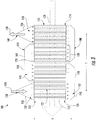
FIG. 1 provides a perspective view of an additively manufactured heat exchanger according to an exemplary embodiment of the present subject matter. -
FIG. 2 provides a cross-sectional view of the exemplary heat exchanger ofFIG. 1 , taken along Line 2-2 ofFIG. 1 . -
FIG. 3 provides a schematic cross-sectional view of the exemplary heat exchanger ofFIG. 1 , illustrating fluid flow directions according to an exemplary embodiment of the present subject matter. -
FIG. 4 provides a close-up, cross-sectional view of a collector manifold of the exemplary heat exchanger ofFIG. 1 according to an exemplary embodiment of the present subject matter. -
FIG. 5 provides a perspective view of a flow splitter the may be used in the exemplary heat exchanger ofFIG. 1 according to an exemplary embodiment of the present subject matter. -
FIG. 6 provides a perspective, cross-sectional view of the exemplary collector manifold ofFIG. 4 according to an exemplary embodiment of the present subject matter. -
FIG. 7 provides another cross-sectional view of the exemplary heat exchanger ofFIG. 1 . -
FIG. 8 provides a cross-sectional view of the exemplary heat exchanger ofFIG. 1 , taken along Line 8-8 ofFIG. 7 . -
FIG. 9 is a method of manufacturing a heat exchanger according to an exemplary embodiment of the present subject matter. - Repeat use of reference characters in the present specification and drawings is intended to represent the same or analogous features or elements of the present invention.
- Reference will now be made in detail to present embodiments of the invention, one or more examples of which are illustrated in the accompanying drawings. The detailed description uses numerical and letter designations to refer to features in the drawings. Like or similar designations in the drawings and description have been used to refer to like or similar parts of the invention. As used herein, the terms "first", "second", and "third" may be used interchangeably to distinguish one component from another and are not intended to signify location or importance of the individual components. The terms "forward" and "aft" refer to relative positions within a gas turbine engine, with forward referring to a position closer to an engine inlet and aft referring to a position closer to an engine nozzle or exhaust. The terms "upstream" and "downstream" refer to the relative direction with respect to fluid flow in a fluid pathway. For example, "upstream"' refers to the direction from which the fluid flows, and "downstream" refers to the direction to which the fluid flows. Furthermore, as used herein, terms of approximation, such as "approximately," "substantially," or "about," refer to being within a ten percent margin of error.
- As used herein, a "fluid" may be a gas or a liquid. The present approach is not limited by the types of fluids that are used. In the preferred application, the cooling fluid is air, and the cooled fluid is oil. The present approach may be used for other types of liquid and gaseous fluids, where the cooled fluid and the cooling fluid are the same fluids or different fluids. Other examples of the cooled fluid and the cooling fluid include fuel, hydraulic fluid, combustion gas, refrigerant, refrigerant mixtures, dielectric fluid for cooling avionics or other aircraft electronic systems, water, water-based compounds, water mixed with antifreeze additives (e.g., alcohol or glycol compounds), and any other organic or inorganic heat transfer fluid or fluid blends capable of persistent heat transport at elevated or reduced temperature.
- The present disclosure is generally directed to a heat exchanger and a method for additively manufacturing the heat exchanger. The heat exchanger includes a housing defining a heat exchange plenum having a first fluid inlet and a first fluid outlet separated along a transverse direction. A plurality of heat exchange banks pass through the heat exchange plenum between a top side and a bottom side of the housing substantially along a vertical direction, each of the heat exchange banks comprising a plurality of heat exchange tubes. A plurality of collector manifolds are positioned at the top side and the bottom side of the housing, each collector manifold defining one or more connecting ports providing fluid communication between adjacent heat exchange banks.
- Referring to
FIG. 1 , an additively manufacturedheat exchanger 100 will be described according to an exemplary embodiment of the present subject matter.Heat exchanger 100 may be used to transfer heat between two or more fluids in any suitable application. For example, as discussed below,heat exchanger 100 is configured for transferring heat from oil to air in a gas turbine engine. However, it should be appreciated thatheat exchanger 100 can be configured for receiving any suitable number and type of fluids for use in the heat transfer process, examples which are described herein. In addition, the concepts and heat exchanging structures disclosed herein could be similarly used in automotive, aviation, maritime, and other industries to assist in heat transfer between fluids. Moreover,FIG. 1 illustrates an exemplary embodiment ofheat exchanger 100 for the purpose of explaining its general operation, but the size, shape, and configuration ofheat exchanger 100 is not intended to limit the scope of the present subject matter. For example, the size, shape, number, and configuration of fluid passageways may be varied while remaining within the scope of the present subject matter. - In general, the exemplary embodiments of
heat exchanger 100 described herein may be manufactured or formed using any suitable process. However, in accordance with several aspects of the present subject matter,heat exchanger 100 may be formed using an additive-manufacturing process, such as a 3-D printing process. The use of such a process may allowheat exchanger 100 to be formed integrally, as a single monolithic component, or as any suitable number of sub-components. In particular, the manufacturing process may allowheat exchanger 100 to be integrally formed and include a variety of features not possible when using prior manufacturing methods. For example, the additive manufacturing methods described herein enable the manufacture of heat exchangers having various features, configurations, thicknesses, materials, densities, fluid passageways, and mounting structures not possible using prior manufacturing methods. Some of these novel features are described herein. - As used herein, the terms "additively manufactured" or "additive manufacturing techniques or processes" refer generally to manufacturing processes wherein successive layers of material(s) are provided on each other to "build-up," layer-by-layer, a three-dimensional component. The successive layers generally fuse together to form a monolithic component which may have a variety of integral sub-components. Although additive manufacturing technology is described herein as enabling fabrication of complex objects by building objects point-by-point, layer-by-layer, typically in a vertical direction, other methods of fabrication are possible and within the scope of the present subject matter. For example, although the discussion herein refers to the addition of material to form successive layers, one skilled in the art will appreciate that the methods and structures disclosed herein may be practiced with any additive manufacturing technique or manufacturing technology. For example, embodiments of the present invention may use layer-additive processes, layer-subtractive processes, or hybrid processes.
- Suitable additive manufacturing techniques in accordance with the present disclosure include, for example, Fused Deposition Modeling (FDM), Selective Laser Sintering (SLS), 3D printing such as by inkjets and laserjets, Sterolithography (SLA), Direct Selective Laser Sintering (DSLS), Electron Beam Sintering (EBS), Electron Beam Melting (EBM), Laser Engineered Net Shaping (LENS), Laser Net Shape Manufacturing (LNSM), Direct Metal Deposition (DMD), Digital Light Processing (DLP), Direct Selective Laser Melting (DSLM), Selective Laser Melting (SLM), Direct Metal Laser Melting (DMLM), and other known processes.
- The additive manufacturing processes described herein may be used for forming components using any suitable material. For example, the material may be plastic, metal, concrete, ceramic, polymer, epoxy, photopolymer resin, or any other suitable material that may be in solid, liquid, powder, sheet material, wire, or any other suitable form. More specifically, according to exemplary embodiments of the present subject matter, the additively manufactured components described herein may be formed in part, in whole, or in some combination of materials including but not limited to pure metals, nickel alloys, chrome alloys, titanium, titanium alloys, magnesium, magnesium alloys, aluminum, aluminum alloys, and nickel or cobalt based superalloys (e.g., those available under the name Inconel® available from Special Metals Corporation). These materials are examples of materials suitable for use in the additive manufacturing processes described herein, and may be generally referred to as "additive materials."
- In addition, one skilled in the art will appreciate that a variety of materials and methods for bonding those materials may be used and are contemplated as within the scope of the present disclosure. As used herein, references to "fusing" may refer to any suitable process for creating a bonded layer of any of the above materials. For example, if an object is made from polymer, fusing may refer to creating a thermoset bond between polymer materials. If the object is epoxy, the bond may be formed by a crosslinking process. If the material is ceramic, the bond may be formed by a sintering process. If the material is powdered metal, the bond may be formed by a melting or sintering process. One skilled in the art will appreciate that other methods of fusing materials to make a component by additive manufacturing are possible, and the presently disclosed subject matter may be practiced with those methods.
- In addition, the additive manufacturing process disclosed herein allows a single component to be formed from multiple materials. Thus, the components described herein may be formed from any suitable mixtures of the above materials. For example, a component may include multiple layers, segments, or parts that are formed using different materials, processes, and/or on different additive manufacturing machines. In this manner, components may be constructed which have different materials and material properties for meeting the demands of any particular application. In addition, although the components described herein are constructed entirely by additive manufacturing processes, it should be appreciated that in alternate embodiments, all or a portion of these components may be formed via casting, machining, and/or any other suitable manufacturing process. Indeed, any suitable combination of materials and manufacturing methods may be used to form these components.
- An exemplary additive manufacturing process will now be described. Additive manufacturing processes fabricate components using three-dimensional (3D) information, for example a three-dimensional computer model, of the component. Accordingly, a three-dimensional design model of the component may be defined prior to manufacturing. In this regard, a model or prototype of the component may be scanned to determine the three-dimensional information of the component. As another example, a model of the component may be constructed using a suitable computer aided design (CAD) program to define the three-dimensional design model of the component.
- The design model may include 3D numeric coordinates of the entire configuration of the component including both external and internal surfaces of the component. For example, the design model may define the body, the surface, and/or internal passageways such as openings, support structures, etc. In one exemplary embodiment, the three-dimensional design model is converted into a plurality of slices or segments, e.g., along a central (e.g., vertical) axis of the component or any other suitable axis. Each slice may define a thin cross section of the component for a predetermined height of the slice. The plurality of successive cross-sectional slices together form the 3D component. The component is then "built-up" slice-by-slice, or layer-by-layer, until finished.
- In this manner, the components described herein may be fabricated using the additive process, or more specifically each layer is successively formed, e.g., by fusing or polymerizing a plastic using laser energy or heat or by sintering or melting metal powder. For example, a particular type of additive manufacturing process may use an energy beam, for example, an electron beam or electromagnetic radiation such as a laser beam, to sinter or melt a powder material. Any suitable laser and laser parameters may be used, including considerations with respect to power, laser beam spot size, and scanning velocity. The build material may be formed by any suitable powder or material selected for enhanced strength, durability, and useful life, particularly at high temperatures.
- Each successive layer may be, for example, between about 10 µm and 200 µm, although the thickness may be selected based on any number of parameters and may be any suitable size according to alternative embodiments. Therefore, utilizing the additive formation methods described above, the components described herein may have cross sections as thin as one thickness of an associated powder layer, e.g., 10 µm, utilized during the additive formation process.
- In addition, utilizing an additive process, the surface finish and features of the components may vary as need depending on the application. For example, the surface finish may be adjusted (e.g., made smoother or rougher) by selecting appropriate laser scan parameters (e.g., laser power, scan speed, laser focal spot size, etc.) during the additive process, especially in the periphery of a cross-sectional layer which corresponds to the part surface. For example, a rougher finish may be achieved by increasing laser scan speed or decreasing the size of the melt pool formed, and a smoother finish may be achieved by decreasing laser scan speed or increasing the size of the melt pool formed. The scanning pattern and/or laser power can also be changed to change the surface finish in a selected area.
- Notably, in exemplary embodiments, several features of the components described herein were previously not possible due to manufacturing restraints. However, the present inventors have advantageously utilized current advances in additive manufacturing techniques to develop exemplary embodiments of such components generally in accordance with the present disclosure. While the present disclosure is not limited to the use of additive manufacturing to form these components generally, additive manufacturing does provide a variety of manufacturing advantages, including ease of manufacturing, reduced cost, greater accuracy, etc.
- In this regard, utilizing additive manufacturing methods, even multi-part components may be formed as a single piece of continuous metal, and may thus include fewer sub-components and/or joints compared to prior designs. The integral formation of these multi-part components through additive manufacturing may advantageously improve the overall assembly process. For example, the integral formation reduces the number of separate parts that must be assembled, thus reducing associated time and overall assembly costs. Additionally, existing issues with, for example, leakage, joint quality between separate parts, and overall performance may advantageously be reduced.
- Also, the additive manufacturing methods described above enable much more complex and intricate shapes and contours of the components described herein. For example, such components may include thin additively manufactured layers and unique fluid passageways with integral collector manifolds. In addition, the additive manufacturing process enables the manufacture of a single component having different materials such that different portions of the component may exhibit different performance characteristics. The successive, additive nature of the manufacturing process enables the construction of these novel features. As a result, the components described herein may exhibit improved heat transfer efficiency and reliability.
- Referring now generally to
FIGS. 1 through 3 ,heat exchanger 100 will be described according to an exemplary embodiment of the present subject matter. As illustrated,heat exchanger 100 includes ahousing 102 that extends between aleft side 104 and aright side 106 along a first direction, e.g., the lateral direction L. In addition,housing 102 also extends between abottom side 108 and atop side 110 along a second direction, e.g., the verticaldirection V. Housing 102 extends between afront side 112 and aback side 114 along a third direction, e.g., the transverse direction T. According to the illustrated embodiment, the lateral direction L, the vertical direction V, and the transverse direction T are mutually perpendicular with one another, such that an orthogonal coordinate system is generally defined. - However, it should be appreciated that the
exemplary heat exchanger 100 and the L-V-T coordinate system are used herein only for the purpose of explaining aspects of the present subject matter and are not intended to limit the scope of the present disclosure. In this regard, directional indicators such as "left" and "right," "top" and "bottom," and "front" and "back" are only used to indicate the relative positioning of various parts ofheat exchanger 100 along the L-direction, the V-direction, and the T-direction, respectively. Moreover, the various parts and features ofexemplary heat exchanger 100 may have a different position, orientation, and configuration while remaining within the scope of the present subject matter. - As illustrated,
housing 102 generally comprises a plurality ofwalls 120 defining aheat exchange plenum 122. More specifically,walls 120 generally form a box having a rectangular cross-section definingheat exchange plenum 122. However, it should be appreciated thatwalls 120 may include fewer or more than four walls joined in any suitable orientation to define a suitably shapedheat exchange plenum 122.Housing 102 further defines a first fluid inlet, referred to herein as anair inlet 124, and a first fluid outlet, referred to herein as anair outlet 126, separated along a first direction, e.g., the transverse direction T. - Therefore, as best illustrated schematically in
FIG. 3 air inlet 124 andair outlet 126 are in fluid communication withheat exchange plenum 122 for allowing a flow of cooling air (indicated byarrow 128 inFIG. 3 ) to pass throughheat exchange plenum 122. According to the illustrated embodiment,air inlet 124 is defined at backside 114 ofhousing 102 andair outlet 126 is defined atfront side 112 ofhousing 102. However, other flow directions may be used according to alternative embodiments. In addition, although the present disclosure describesheat exchanger 100 being configured for passing air throughheat exchange plenum 122, it should be appreciated that any suitable heat exchange fluid may be used according to alternative embodiments. -
Heat exchanger 100 further includes a plurality ofheat exchange banks 130 positioned within and passing throughheat exchange plenum 122 betweentop side 110 andbottom side 108 ofhousing 102 substantially along a second direction, e.g., the vertical direction V. Eachheat exchange bank 130 includes a plurality ofheat exchange tubes 132. As best illustrated schematically inFIG. 3 ,heat exchange banks 130 are generally configured to receive a flow of hot oil (indicated byarrow 134 inFIG. 3 ) which passes throughheat exchange tubes 132 substantially along the vertical direction V between a first end ofheat exchange bank 130 proximatetop side 110 ofhousing 102 and a second end ofheat exchange bank 130 proximatebottom side 108 ofhousing 102. -
Heat exchanger 100 further includes a plurality ofcollector manifolds 140 positioned attop side 110 andbottom side 108 ofhousing 102.Collector manifolds 140 definecollector plenums 142 that provide fluid communication between adjacentheat exchange banks 130 and a continuous fluid passageway for the flow ofhot oil 134 to pass throughheat exchanger 100. As illustrated, eachcollector manifold 140 defines one or more connectingports 144 that provide fluid communication between adjacentheat exchange banks 130. In this regard, connectingports 144 are apertures defined individer walls 146 that divide adjacentheat exchange banks 130. More specifically,collector manifolds 140 define connectingports 144 on alternatingdivider walls 146, such that a serpentine flow path is generally defined. - Notably,
heat exchange banks 130 andheat exchange tubes 132 are illustrated as passing up and down along the vertical direction V. By passinghot oil 134 throughcollector plenums 142 and connectingports 144 as described above, the flow ofhot oil 134 also passes in a serpentine pattern along the transverse direction T. In this manner,hot oil 134 from eachheat exchange tube 132 within aheat exchange bank 130 will flow into therespective collector plenum 142 where the oil will mix together before passing through connectingports 144 into the adjacentheat exchange bank 130. Such a configuration ensures even temperature distribution within a flow ofhot oil 134 and improves heat transfer efficiency. - Although
heat exchange tubes 132 are illustrated as being straight tubes routed in a serpentine manner, it should be appreciated that according to alternative embodiments, eachheat exchange tube 132 may be curvilinear, serpentine, helical, sinusoidal, or any other suitable shape. In addition,heat exchange tubes 132 may be formed in any suitable size, number, spacing, shape, orientation, and number of passes as needed depending on the application and the type of heat exchange fluid. These various configurations are enabled by the additive manufacturing processes disclosed herein and are considered to be within the scope of the present subject matter. - In addition,
heat exchanger 100 is illustrated as having fourheat exchange banks 130 and eachheat exchange bank 130 as having five rows ofheat exchange tubes 132. However, it should be appreciated that according to alternative embodiments, fewer or more than fourheat exchange banks 130 and fewer or more than fiveheat exchange tubes 132 may be used. In addition,heat exchange banks 130 andheat exchange tubes 132 may have any suitable size and/or configuration as needed for a given application. - Referring specifically to
FIGS. 1 through 4 ,heat exchanger 100 further includes aninlet manifold 150 positioned proximatefront side 112 andtop side 110 ofhousing 102 and defining aninlet plenum 152. In addition,heat exchanger 100 further includes anoutlet manifold 154 positioned proximateback side 114 andtop side 110 ofhousing 102 and defining anoutlet plenum 156.Inlet plenum 152 andoutlet plenum 156 are in direct fluid communication with a firstheat exchange bank 130 and a lastheat exchange bank 130, respectively. Therefore, during operation ofheat exchanger 100, the flow ofoil 134 passes through a second fluid inlet, referred to herein as anoil inlet 158 and intoinlet plenum 152. The flow ofoil 134 then passes throughheat exchange banks 130 andcollector plenums 142 in a serpentine manner as described above. Finally, the flow ofoil 134 exitsheat exchanger 100 throughoutlet plenum 156 and a second fluid outlet, referred to herein as anoil outlet 160. In this manner, a continuous passageway forhot oil 134 is defined throughheat exchange plenum 122 such that thermal energy may be transferred from the flow ofhot oil 134 to the flow of coolingair 128 passing throughheat exchange plenum 122. -
Heat exchanger 100 is described herein as passing coolingair 128 throughheat exchange plenum 122 generally along the first direction, i.e., the transverse direction T, and passinghot oil 134 throughheat exchange tubes 132 generally along the second direction, i.e., the vertical direction V, such that the flows are perpendicular to each other and in a cross-flow heat exchange arrangement. However, it should be appreciated that the directional orientation ofheat exchange tubes 132 relative tohousing 102 andheat exchange plenum 122 may vary while remaining within the scope of the present subject matter. In this regard, according to alternative embodiments,heat exchange tubes 132 may be configured in another cross-flow orientation withheat exchange plenum 122, in a parallel flow arrangement, or in any other suitable orientation. In addition, as described in detail above, any suitable alternative heat exchange fluids may be used. - Using the additive manufacturing techniques described herein,
heat exchanger 100 may further include a variety of features that improve operation ofheat exchanger 100. Some exemplary features are described below which may improve the structural rigidity ofheat exchanger 100, may improve fluid flow throughheat exchanger 100, may improve heat transfer efficiency ofheat exchanger 100, or may otherwise improve the operation ofheat exchanger 100. - For example, referring to
FIGS. 2 ,4 , and5 ,heat exchanger 100 may include one ormore flow splitters 170 positioned withininlet plenum 152.Flow splitters 170 withininlet manifold 150 generally extend between a locationproximate oil inlet 158 to a location proximate to the firstheat exchange bank 130 or the inlets ofheat exchange tubes 132. Similarly, flowsplitters 170 are positioned withinoutlet plenum 156 and generally extend between a location proximate the lastheat exchange bank 130 or the outlets ofheat exchange tubes 132 to a locationproximate oil outlet 160. -
Flow splitters 170 are generally shaped to assist in splitting or merging the flow ofoil 134 in a uniform manner while reducing flow losses and pressure drops. According to the illustrated embodiment, at least oneflow splitter 170 extends within a first plane perpendicular to the transverse direction T and at least oneflow splitter 170 extends along the transverse direction T. However, flowsplitters 170 may have any suitable shape for directing the flow ofoil 134 to achieve an even flow distribution among theheat exchange tubes 132 within the firstheat exchange bank 130 and for efficiently merging the flow ofoil 134 from the lastheat exchange bank 130 withinoutlet plenum 156. - As best illustrated in
FIGS. 2 and6 ,heat exchanger 100 further includes a plurality of stiffeningribs 176 defined bycollector manifolds 140 and positioned withincollector plenums 142. Stiffeningribs 176 extend substantially along the vertical direction V between adjacentheat exchange banks 130 and at least partially defining the connectingports 144. Stiffeningribs 176 may generally be shaped to increase the structural rigidity ofcollector manifold 130 and decrease the stagnation of fluid flow withincollector plenum 142. For example, as illustrated, stiffeningribs 176 are substantiallytriangular stiffening ribs 176, with a base of the triangle being positioned at abottom wall 178 ofcollector manifold 140 along the vertical direction V and extending toward and supportingdivider wall 146. Other shapes, configurations, and orientations are possible according to alternative embodiments. - As best illustrated in
FIGS. 1 ,2 , and7 ,heat exchanger 100 further includes a plurality of stiffeningplates 182 that extend along a plane substantially perpendicular to the vertical direction V and rigidly couple the plurality ofheat exchange tubes 132. As illustrated,heat exchanger 100 includes nine horizontally oriented stiffening plates that provide structural rigidity and an improved frequency response ofheat exchanger 100. Stiffeningplates 182 also act to divide the flow of coolingair 128 along the vertical direction V to provide a more uniform flow distribution. However, according to alternative embodiments, any suitable number, position, orientation, and configuration of stiffeningplates 182 may be used. - Referring now to
FIGS. 7 and 8 ,heat exchanger 100 further includes a plurality ofwave stiffeners 184 positioned withincollector plenums 142 and extending substantially along the vertical direction V to divide the flow ofhot oil 134 along the lateral direction L. According to the illustrated embodiment,wave stiffeners 184 have a sinusoidal shape and define a width 186 (FIG. 8 ) measured betweenwave stiffeners 184 along the lateral direction L that is approximately equivalent to a width 188 (FIG. 4 ) of a singleheat exchange bank 130 taken along the transverse direction T. However, according to alternative embodiments, any suitable number, size, position, orientation, and configuration ofwave stiffeners 184 may be used. - The various portions of
heat exchanger 100 may be constructed using any suitable material, in any suitable geometry, density, and thickness, as needed to provide necessary structural support toheat exchanger 100. For example,housing 102 ofheat exchanger 100 may be formed from a rigid, thermally insulating material. In addition,housing 102 may be thicker and denser to provide structural support for loads experienced byheat exchanger 100 during mounting, assembly, and operation. By contrast,heat exchange tubes 132 may be thinner and constructed of a more thermally conductive material in order to enhance heat transfer. For example,heat exchange tubes 132 may have a wall thickness of 20 µm or any other suitable thickness. - It should be appreciated that
heat exchanger 100 is described herein only for the purpose of explaining aspects of the present subject matter. For example,heat exchanger 100 will be used herein to describe exemplary configurations, constructions, and methods ofmanufacturing heat exchanger 100. It should be appreciated that the additive manufacturing techniques discussed herein may be used to manufacture other heat exchangers for use in any suitable device, for any suitable purpose, and in any suitable industry. Thus, the exemplary components and methods described herein are used only to illustrate exemplary aspects of the present subject matter and are not intended to limit the scope of the present disclosure in any manner. - Now that the construction and configuration of
heat exchanger 100 according to an exemplary embodiment of the present subject matter has been presented, anexemplary method 200 for forming a heat exchanger according to an exemplary embodiment of the present subject matter is provided.Method 200 can be used by a manufacturer to formheat exchanger 100, or any other suitable heat exchanger. It should be appreciated that theexemplary method 200 is discussed herein only to describe exemplary aspects of the present subject matter, and is not intended to be limiting. - Referring now to
FIG. 9 ,method 200 includes, atstep 210, depositing a layer of additive material on a bed of an additive manufacturing machine.Method 200 further includes, atstep 220, selectively directing energy from an energy source onto the layer of additive material to fuse a portion of the additive material and form a heat exchanger. For example, using the example from above,heat exchanger 100 may be formed for transferring heat between air and oil, or any other suitable heat exchanger may be formed. - The heat exchanger formed at
step 220 may include a housing defining a heat exchange plenum having a first fluid inlet and a first fluid outlet separated along a transverse direction. A plurality of heat exchange banks pass through the heat exchange plenum between a top side and a bottom side of the housing substantially along a vertical direction, each of the heat exchange banks including a plurality of heat exchange tubes. A plurality of collector manifolds are positioned at the top side and the bottom side of the housing, each collector manifold defining one or more connecting ports providing fluid communication between adjacent heat exchange banks. - According to exemplary embodiments,
method 200 may further include using the additive manufacturing methods described herein to form an integral inlet manifold and outlet manifold. Inlet manifold is positioned proximate the front side of the housing and defines an inlet plenum in direct fluid communication with a first heat exchange bank. One or more flow splitters are positioned within the inlet plenum and extend between a second fluid inlet and the first heat exchange bank. Outlet manifold is positioned proximate the back side of the housing and defines an outlet plenum in direct fluid communication with a last heat exchange bank. Similarly, one or more flow splitters are positioned within the outlet plenum and extend between the last heat exchange bank and a second fluid outlet. Notably, according to an exemplary embodiment, the housing, the heat exchange banks, the collector manifolds, the inlet manifold, the outlet manifold, and other parts of the heat exchanger such as described above are integrally formed as a single monolithic component. -
FIG. 9 depicts steps performed in a particular order for purposes of illustration and discussion. Those of ordinary skill in the art, using the disclosures provided herein, will understand that the steps of any of the methods discussed herein can be adapted, rearranged, expanded, omitted, or modified in various ways without deviating from the scope of the present disclosure. Moreover, although aspects ofmethod 200 are explained usingheat exchanger 100 as an example, it should be appreciated that these methods may be applied to manufacture any suitable heat exchanger. - An additively manufactured heat exchanger and a method for manufacturing that heat exchanger are described above. Notably,
heat exchanger 100 may generally include performance-enhancing geometries and heat exchanging features whose practical implementations are facilitated by an additive manufacturing process, as described below. For example, using the additive manufacturing methods described herein, the heat exchanger may include a heat exchange structure for transferring thermal energy between two streams of fluid. In addition, the additively manufacturing techniques described herein enable the formation of a heat exchanger with integral collector manifolds which improve the thermal efficiency of the heat exchanger. These features may be introduced during the design of the heat exchanger, such that they may be easily integrated into heat exchanger during the build process at little or no additional cost. Moreover, the entire heat exchanger, including the housing, the heat exchange banks, the collector manifolds, the inlet manifold, the outlet manifold, the flow splitters, and other features can be formed integrally as a single monolithic component. - This written description uses examples to disclose the invention, including the best mode, and also to enable any person skilled in the art to practice the invention, including making and using any devices or systems and performing any incorporated methods. The patentable scope of the invention is defined by the claims, and may include other examples that occur to those skilled in the art. Such other examples are intended to be within the scope of the claims if they include structural elements that do not differ from the literal language of the claims, or if they include equivalent structural elements with insubstantial differences from the literal languages of the claims.
Claims (20)
- A heat exchanger defining a vertical direction, a lateral direction, and a transverse direction, the vertical, lateral, and transverse directions being mutually perpendicular to each other, the heat exchanger comprising:a housing defining a heat exchange plenum having a first fluid inlet and a first fluid outlet separated along the transverse direction;a plurality of heat exchange banks passing through the heat exchange plenum between a top side and a bottom side of the housing substantially along the vertical direction, each of the heat exchange banks comprising a plurality of heat exchange tubes; anda plurality of collector manifolds positioned at the top side and the bottom side of the housing, each collector manifold defining one or more connecting ports providing fluid communication between adjacent heat exchange banks.
- The heat exchanger of claim 1, wherein the housing defines a front side and a back side separated along the transverse direction, the heat exchanger further comprising:an inlet manifold positioned proximate the front side of the housing and defining an inlet plenum in direct fluid communication with a first heat exchange bank;andan outlet manifold positioned proximate the back side of the housing and defining an outlet plenum in direct fluid communication with a last heat exchange bank.
- The heat exchanger of claim 2, further comprising:at least one inlet manifold or outlet manifold in fluid communication with an intermediate heat bank positioned between the first heat exchange bank and the last heat exchange bank along the transverse direction.
- The heat exchanger of claim 2, wherein the heat exchanger comprises:one or more flow splitters positioned within the inlet plenum and extending between a second fluid inlet and the first heat exchange bank; andone or more flow splitters positioned within the outlet plenum and extending between the last heat exchange bank and a second fluid outlet.
- The heat exchanger of claim 4, wherein at least one of the flow splitters extends within a first plane perpendicular to the transverse direction and at least one of the flow splitters extends along the transverse direction.
- The heat exchanger of claim 2, wherein the first fluid inlet is defined at the back side of the housing and the first fluid outlet is defined at the front side of the housing.
- The heat exchanger of claim 2, wherein the housing, the heat exchange tubes, the inlet manifold, the outlet manifold, and the collector manifolds are integrally formed as a single monolithic component.
- The heat exchanger of claim 1, further comprising:a plurality of stiffening plates that extend along a plane substantially perpendicular to the vertical direction and rigidly couple the plurality of heat exchange tubes.
- The heat exchanger of claim 1, further comprising:a plurality of wave stiffeners positioned within the collector manifolds and extending substantially along the vertical direction.
- The heat exchanger of claim 9, wherein the plurality of wave stiffeners have a sinusoidal shape and divide a flow of fluid within the collector manifolds along the lateral direction.
- The heat exchanger of claim 1, further comprising:a plurality of stiffening ribs positioned within the collector manifold, the stiffening ribs extending substantially along the vertical direction between adjacent heat exchange banks and at least partially defining the connecting ports.
- The heat exchanger of claim 11, wherein the stiffening ribs are substantially triangular stiffening ribs, with a base of the triangular stiffening ribs being positioned at a bottom of the collector manifold along the vertical direction.
- The heat exchanger of claim 1, wherein the heat exchanger comprises a plurality of layers formed by:depositing a layer of additive material on a bed of an additive manufacturing machine; andselectively directing energy from an energy source onto the layer of additive material to fuse a portion of the additive material.
- A method of manufacturing a heat exchanger, the method comprising:depositing a layer of additive material on a bed of an additive manufacturing machine; andselectively directing energy from an energy source onto the layer of additive material to fuse a portion of the additive material and form a heat exchanger defining a vertical direction, a lateral direction, and a transverse direction, the vertical, lateral, and transverse directions being mutually perpendicular to each other, the heat exchanger comprising:a housing defining a heat exchange plenum having a first fluid inlet and a first fluid outlet separated along the transverse direction;a plurality of heat exchange banks passing through the heat exchange plenum between a top side and a bottom side of the housing substantially along the vertical direction, each of the heat exchange banks comprising a plurality of heat exchange tubes; andat least one collector manifold providing fluid communication between adjacent heat exchange banks.
- The method of claim 14, wherein the heat exchanger comprises:a plurality of collector manifolds positioned at the top side and the bottom side of the housing, each of the collector manifolds defining one or more connecting ports providing fluid communication between adjacent heat exchange banks.
- The method of claim 14, wherein the housing defines a front side and a back side separated along the transverse direction, the method further comprising:forming an inlet manifold positioned proximate the front side of the housing and defining an inlet plenum in direct fluid communication with a first heat exchange bank, one or more flow splitters positioned within the inlet plenum and extending between a second fluid inlet and the first heat exchange bank; andforming an outlet manifold positioned proximate the back side of the housing and defining an outlet plenum in direct fluid communication with a last heat exchange bank, one or more flow splitters positioned within the outlet plenum and extending between the last heat exchange bank and a second fluid outlet.
- The method of claim 14, further comprising:forming a plurality of stiffening plates that extend along a plane perpendicular to the vertical direction and rigidly couple the plurality of heat exchange tubes.
- The method of claim 14, further comprising:forming a plurality of wave stiffeners positioned within the at least one collector manifold and extending substantially along the vertical direction and having a sinusoidal shape that divides a flow of fluid within the at least one collector manifold along the lateral direction.
- The method of claim 15, further comprising:forming a plurality of stiffening ribs positioned within the collector manifolds, the stiffening ribs extending substantially along the vertical direction between adjacent heat exchange banks and at least partially defining the connecting ports.
- A heat exchanger comprising:a housing defining a heat exchange plenum extending substantially along a first direction;a plurality of heat exchange banks positioned within the heat exchanger plenum and extending between a first end and a second end substantially along a second direction, each of the heat exchange banks comprising a plurality of heat exchange tubes; anda plurality of collector manifolds positioned at the first end and the second end of the heat exchange banks, each collector manifold defining one or more connecting ports providing fluid communication between adjacent heat exchange banks, the connecting ports being at least partially defined by a plurality of stiffening ribs extending substantially along the second direction.
Priority Applications (5)
| Application Number | Priority Date | Filing Date | Title |
|---|---|---|---|
| EP17425058.9A EP3410054B1 (en) | 2017-05-30 | 2017-05-30 | Additively manufactured heat exchanger |
| CA3005197A CA3005197A1 (en) | 2017-05-30 | 2018-05-17 | Additively manufactured heat exchanger |
| JP2018100270A JP2019027772A (en) | 2017-05-30 | 2018-05-25 | Additively manufactured heat exchanger |
| CN201810539197.4A CN108979865A (en) | 2017-05-30 | 2018-05-30 | The heat exchanger of increasing material manufacturing |
| US15/992,779 US10583535B2 (en) | 2017-05-30 | 2018-05-30 | Additively manufactured heat exchanger |
Applications Claiming Priority (1)
| Application Number | Priority Date | Filing Date | Title |
|---|---|---|---|
| EP17425058.9A EP3410054B1 (en) | 2017-05-30 | 2017-05-30 | Additively manufactured heat exchanger |
Publications (2)
| Publication Number | Publication Date |
|---|---|
| EP3410054A1 true EP3410054A1 (en) | 2018-12-05 |
| EP3410054B1 EP3410054B1 (en) | 2022-10-26 |
Family
ID=59315569
Family Applications (1)
| Application Number | Title | Priority Date | Filing Date |
|---|---|---|---|
| EP17425058.9A Active EP3410054B1 (en) | 2017-05-30 | 2017-05-30 | Additively manufactured heat exchanger |
Country Status (5)
| Country | Link |
|---|---|
| US (1) | US10583535B2 (en) |
| EP (1) | EP3410054B1 (en) |
| JP (1) | JP2019027772A (en) |
| CN (1) | CN108979865A (en) |
| CA (1) | CA3005197A1 (en) |
Cited By (13)
| Publication number | Priority date | Publication date | Assignee | Title |
|---|---|---|---|---|
| EP3531057A1 (en) * | 2018-02-23 | 2019-08-28 | Unison Industries LLC | Heat exchanger assembly |
| EP3540358A1 (en) * | 2018-03-16 | 2019-09-18 | Hamilton Sundstrand Corporation | Integral heat exchanger manifold guide vanes and supports |
| EP3719432A1 (en) * | 2019-04-01 | 2020-10-07 | Hamilton Sundstrand Corporation | Heat exchanger fractal splitter |
| US10926364B2 (en) | 2018-10-03 | 2021-02-23 | Hamilton Sundstrand Corporation | Plate-fin heat exchanger core design for improved manufacturing |
| EP3789719A1 (en) * | 2019-09-06 | 2021-03-10 | Hamilton Sundstrand Corporation | Heat exchanger with radially converging manifold |
| US11209222B1 (en) | 2020-08-20 | 2021-12-28 | Hamilton Sundstrand Corporation | Spiral heat exchanger header |
| DE102020210310A1 (en) | 2020-08-13 | 2022-02-17 | Thyssenkrupp Ag | Compact heat exchanger |
| US11274886B2 (en) | 2019-03-08 | 2022-03-15 | Hamilton Sundstrand Corporation | Heat exchanger header with fractal geometry |
| US11280550B2 (en) | 2019-03-08 | 2022-03-22 | Hamilton Sundstrand Corporation | Radially layered helical core geometry for heat exchanger |
| CN114413675A (en) * | 2021-12-15 | 2022-04-29 | 合肥通用机械研究院有限公司 | Pipeline with Laval structure on inner surface and additive manufacturing method thereof |
| US11359864B2 (en) | 2019-03-08 | 2022-06-14 | Hamilton Sundstrand Corporation | Rectangular helical core geometry for heat exchanger |
| EP4177560A1 (en) * | 2021-11-05 | 2023-05-10 | Hamilton Sundstrand Corporation | Integrally formed flow distributor for fluid manifold |
| US11686530B2 (en) | 2018-03-16 | 2023-06-27 | Hamilton Sundstrand Corporation | Plate fin heat exchanger flexible manifold |
Families Citing this family (19)
| Publication number | Priority date | Publication date | Assignee | Title |
|---|---|---|---|---|
| US10871334B2 (en) | 2013-07-03 | 2020-12-22 | Hamilton Sundstrand Corporation | Heat exchangers with multi-layer structures |
| US9987508B2 (en) * | 2016-08-31 | 2018-06-05 | Emerson Process Management Regulator Technologies Tulsa, Llc | Hybrid composite flame cell |
| US10247296B2 (en) * | 2016-12-12 | 2019-04-02 | General Electric Company | Additively manufactured gearbox with integral heat exchanger |
| DE102017004671A1 (en) * | 2017-05-16 | 2018-11-22 | Degner Gmbh & Co. Kg | Device for cooling, heating or heat transfer |
| US11453158B2 (en) * | 2018-11-16 | 2022-09-27 | Wisconsin Alumni Research Foundation | 3D structures and methods therefor |
| US10981335B2 (en) * | 2019-02-06 | 2021-04-20 | Caterpillar Inc. | Filtration media packs produced using additive manufacturing |
| IT201900012924A1 (en) * | 2019-07-25 | 2021-01-25 | Ge Avio Srl | INTEGRATED SUB-COOLING SYSTEM |
| US11255614B2 (en) | 2019-07-29 | 2022-02-22 | Hamilton Sundstrand Corporation | Heat exchanger with barrier passages |
| US11397062B2 (en) | 2019-11-14 | 2022-07-26 | Hamilton Sundstrand Corporation | Self-supporting additively-manufactured heat exchanger header |
| US20210254904A1 (en) * | 2020-02-19 | 2021-08-19 | The Boeing Company | Additively manufactured heat exchanger |
| EP4111109A1 (en) * | 2020-02-27 | 2023-01-04 | Johnson Controls Tyco IP Holdings LLP | Water box mixing manifold |
| US11460197B1 (en) * | 2020-04-13 | 2022-10-04 | Anthony Staniulis, Jr. | Air transfer apparatus integrally formed with a cavity and for adapting with a heat exchanger |
| EP3904819B1 (en) | 2020-04-27 | 2023-09-27 | Hamilton Sundstrand Corporation | Heat exchanger header fabricated with integral flange using additive metal process |
| CN111922335B (en) * | 2020-05-09 | 2021-10-08 | 同济大学 | Additive manufacturing method of gas-liquid dual-phase heat exchanger |
| US11555659B2 (en) * | 2020-12-18 | 2023-01-17 | Hamilton Sundstrand Corporation | Multi-scale heat exchanger core |
| JP2022149690A (en) * | 2021-03-25 | 2022-10-07 | 株式会社デンソー | Refrigeration cycle device |
| US11389996B1 (en) * | 2021-05-18 | 2022-07-19 | Anthony Staniulis, Jr. | Method of making a monolithic and integral air transfer apparatus |
| US11260565B1 (en) * | 2021-05-18 | 2022-03-01 | Anthony Staniulis, Jr. | Method of making a monolithic air transfer apparatus |
| US11493286B1 (en) * | 2021-10-12 | 2022-11-08 | Hamilton Sundstrand Corporation | Header for high-pressure heat exchanger |
Citations (4)
| Publication number | Priority date | Publication date | Assignee | Title |
|---|---|---|---|---|
| EP0622599A2 (en) * | 1993-04-30 | 1994-11-02 | Sanden Corporation | Heat exchanger |
| US20060090888A1 (en) * | 2004-11-03 | 2006-05-04 | Forward Electronics Co., Ltd. | Heat-exchange type cooler |
| WO2014041771A1 (en) * | 2012-09-13 | 2014-03-20 | 株式会社デンソー | Heat exchanger |
| US20160116218A1 (en) * | 2014-10-27 | 2016-04-28 | Ebullient, Llc | Heat exchanger with helical passageways |
Family Cites Families (22)
| Publication number | Priority date | Publication date | Assignee | Title |
|---|---|---|---|---|
| NL9201945A (en) | 1992-11-05 | 1994-06-01 | Level Energietech Bv | Heat exchanger. |
| JP2000039288A (en) * | 1998-07-21 | 2000-02-08 | Showa Alum Corp | Header for heat exchanger |
| FR2838183B1 (en) | 2002-04-09 | 2004-07-09 | Snecma Propulsion Solide | HIGH TEMPERATURE HEAT EXCHANGER STRUCTURE |
| JP4544575B2 (en) * | 2003-06-11 | 2010-09-15 | 臼井国際産業株式会社 | EGR gas cooling device |
| JP2007183076A (en) * | 2006-01-10 | 2007-07-19 | Denso Corp | Heat exchanger |
| US7810552B2 (en) | 2006-12-20 | 2010-10-12 | The Boeing Company | Method of making a heat exchanger |
| US7866377B2 (en) | 2006-12-20 | 2011-01-11 | The Boeing Company | Method of using minimal surfaces and minimal skeletons to make heat exchanger components |
| EP2015017A1 (en) * | 2007-07-12 | 2009-01-14 | Hexion Specialty Chemicals Research Belgium S.A. | Heat exchanger |
| US8517086B2 (en) | 2008-02-29 | 2013-08-27 | Caterpillar Inc. | Composite heat exchanger end structure |
| JP2011002195A (en) * | 2009-06-22 | 2011-01-06 | Tokyo Electric Power Co Inc:The | Heat exchanger and ice storage type air conditioning system |
| US20120012292A1 (en) * | 2010-07-16 | 2012-01-19 | Evapco, Inc. | Evaporative heat exchange apparatus with finned elliptical tube coil assembly |
| FR2965606B1 (en) * | 2010-09-30 | 2015-04-17 | Valeo Systemes Thermiques | HEAT EXCHANGER FOR MOTOR VEHICLE |
| KR101407144B1 (en) * | 2013-01-24 | 2014-06-13 | 현대중공업 주식회사 | An intake device for a charge air cooler |
| CN104956173B (en) * | 2013-01-25 | 2018-01-05 | 翰昂汽车零部件有限公司 | Equipped with the heat exchanger and its manufacture method in cold-storage portion |
| US20140284038A1 (en) | 2013-03-21 | 2014-09-25 | Hamilton Sundstrand Corporation | Heat exchanger design and fabrication |
| WO2015077490A1 (en) | 2013-11-20 | 2015-05-28 | Carl Schalansky | Method of using additive materials for production of fluid flow channels |
| JP6174655B2 (en) | 2014-10-21 | 2017-08-02 | ユナイテッド テクノロジーズ コーポレイションUnited Technologies Corporation | Ducted heat exchanger system for gas turbine engine and method for manufacturing heat exchanger for gas turbine engine |
| JP2016145662A (en) * | 2015-02-06 | 2016-08-12 | 株式会社デンソー | Heat exchanger and manufacturing method of the same |
| WO2016131139A1 (en) * | 2015-02-18 | 2016-08-25 | Dana Canada Corporation | Stacked plate heat exchanger with top and bottom manifolds |
| WO2016138997A1 (en) * | 2015-03-05 | 2016-09-09 | Linde Aktiengesellschaft | 3d-printed heating surface element for a plate heat exchanger |
| JP6577282B2 (en) * | 2015-08-07 | 2019-09-18 | カルソニックカンセイ株式会社 | Heat exchanger |
| US20180292146A1 (en) * | 2017-04-10 | 2018-10-11 | United Technologies Corporation | Partially additively manufactured heat exchanger |
-
2017
- 2017-05-30 EP EP17425058.9A patent/EP3410054B1/en active Active
-
2018
- 2018-05-17 CA CA3005197A patent/CA3005197A1/en not_active Abandoned
- 2018-05-25 JP JP2018100270A patent/JP2019027772A/en not_active Ceased
- 2018-05-30 CN CN201810539197.4A patent/CN108979865A/en active Pending
- 2018-05-30 US US15/992,779 patent/US10583535B2/en active Active
Patent Citations (4)
| Publication number | Priority date | Publication date | Assignee | Title |
|---|---|---|---|---|
| EP0622599A2 (en) * | 1993-04-30 | 1994-11-02 | Sanden Corporation | Heat exchanger |
| US20060090888A1 (en) * | 2004-11-03 | 2006-05-04 | Forward Electronics Co., Ltd. | Heat-exchange type cooler |
| WO2014041771A1 (en) * | 2012-09-13 | 2014-03-20 | 株式会社デンソー | Heat exchanger |
| US20160116218A1 (en) * | 2014-10-27 | 2016-04-28 | Ebullient, Llc | Heat exchanger with helical passageways |
Cited By (21)
| Publication number | Priority date | Publication date | Assignee | Title |
|---|---|---|---|---|
| US20230115699A1 (en) * | 2018-02-23 | 2023-04-13 | Unison Industries, Llc | Heat exchanger assembly |
| EP3531057A1 (en) * | 2018-02-23 | 2019-08-28 | Unison Industries LLC | Heat exchanger assembly |
| US11927405B2 (en) * | 2018-02-23 | 2024-03-12 | Unison Industries, Llc | Heat exchanger assembly with unitary body and manifold and methods of formng same |
| US11536521B2 (en) | 2018-02-23 | 2022-12-27 | Unison Industries, Llc | Heat exchanger assembly with a manifold additively manufactured onto a core and method of forming |
| EP3540358A1 (en) * | 2018-03-16 | 2019-09-18 | Hamilton Sundstrand Corporation | Integral heat exchanger manifold guide vanes and supports |
| US10443959B2 (en) | 2018-03-16 | 2019-10-15 | Hamilton Sundstrand Corporation | Integral heat exchanger manifold guide vanes and supports |
| US11686530B2 (en) | 2018-03-16 | 2023-06-27 | Hamilton Sundstrand Corporation | Plate fin heat exchanger flexible manifold |
| US10926364B2 (en) | 2018-10-03 | 2021-02-23 | Hamilton Sundstrand Corporation | Plate-fin heat exchanger core design for improved manufacturing |
| US11359864B2 (en) | 2019-03-08 | 2022-06-14 | Hamilton Sundstrand Corporation | Rectangular helical core geometry for heat exchanger |
| US11274886B2 (en) | 2019-03-08 | 2022-03-15 | Hamilton Sundstrand Corporation | Heat exchanger header with fractal geometry |
| US11280550B2 (en) | 2019-03-08 | 2022-03-22 | Hamilton Sundstrand Corporation | Radially layered helical core geometry for heat exchanger |
| EP3719432A1 (en) * | 2019-04-01 | 2020-10-07 | Hamilton Sundstrand Corporation | Heat exchanger fractal splitter |
| US11226158B2 (en) | 2019-04-01 | 2022-01-18 | Hamilton Sundstrand Corporation | Heat exchanger fractal splitter |
| EP3789719A1 (en) * | 2019-09-06 | 2021-03-10 | Hamilton Sundstrand Corporation | Heat exchanger with radially converging manifold |
| US11268770B2 (en) | 2019-09-06 | 2022-03-08 | Hamilton Sunstrand Corporation | Heat exchanger with radially converging manifold |
| WO2022033947A1 (en) | 2020-08-13 | 2022-02-17 | Thyssenkrupp Marine Systems Gmbh | Compact heat exchanger |
| DE102020210310A1 (en) | 2020-08-13 | 2022-02-17 | Thyssenkrupp Ag | Compact heat exchanger |
| US11209222B1 (en) | 2020-08-20 | 2021-12-28 | Hamilton Sundstrand Corporation | Spiral heat exchanger header |
| EP4177560A1 (en) * | 2021-11-05 | 2023-05-10 | Hamilton Sundstrand Corporation | Integrally formed flow distributor for fluid manifold |
| CN114413675A (en) * | 2021-12-15 | 2022-04-29 | 合肥通用机械研究院有限公司 | Pipeline with Laval structure on inner surface and additive manufacturing method thereof |
| CN114413675B (en) * | 2021-12-15 | 2023-10-13 | 合肥通用机械研究院有限公司 | Pipeline with Laval structure on inner surface and additive manufacturing method thereof |
Also Published As
| Publication number | Publication date |
|---|---|
| CN108979865A (en) | 2018-12-11 |
| US10583535B2 (en) | 2020-03-10 |
| CA3005197A1 (en) | 2018-11-30 |
| JP2019027772A (en) | 2019-02-21 |
| US20180345425A1 (en) | 2018-12-06 |
| EP3410054B1 (en) | 2022-10-26 |
Similar Documents
| Publication | Publication Date | Title |
|---|---|---|
| US10583535B2 (en) | Additively manufactured heat exchanger | |
| US10830540B2 (en) | Additively manufactured heat exchanger | |
| CA3011119C (en) | Additively manufactured heat exchanger | |
| US10434575B2 (en) | Additively manufactured heat exchanger including flow turbulators defining internal fluid passageways | |
| US11561048B2 (en) | Circular crossflow heat exchanger | |
| US11236674B2 (en) | Additively manufactured heat exchanger | |
| US10670349B2 (en) | Additively manufactured heat exchanger | |
| US20190024988A1 (en) | Header assembly for a heat exchanger | |
| EP3825638B1 (en) | Integrated horn structures for heat exchanger headers |
Legal Events
| Date | Code | Title | Description |
|---|---|---|---|
| PUAI | Public reference made under article 153(3) epc to a published international application that has entered the european phase |
Free format text: ORIGINAL CODE: 0009012 |
|
| STAA | Information on the status of an ep patent application or granted ep patent |
Free format text: STATUS: THE APPLICATION HAS BEEN PUBLISHED |
|
| AK | Designated contracting states |
Kind code of ref document: A1 Designated state(s): AL AT BE BG CH CY CZ DE DK EE ES FI FR GB GR HR HU IE IS IT LI LT LU LV MC MK MT NL NO PL PT RO RS SE SI SK SM TR |
|
| AX | Request for extension of the european patent |
Extension state: BA ME |
|
| STAA | Information on the status of an ep patent application or granted ep patent |
Free format text: STATUS: REQUEST FOR EXAMINATION WAS MADE |
|
| 17P | Request for examination filed |
Effective date: 20190603 |
|
| RBV | Designated contracting states (corrected) |
Designated state(s): AL AT BE BG CH CY CZ DE DK EE ES FI FR GB GR HR HU IE IS IT LI LT LU LV MC MK MT NL NO PL PT RO RS SE SI SK SM TR |
|
| GRAP | Despatch of communication of intention to grant a patent |
Free format text: ORIGINAL CODE: EPIDOSNIGR1 |
|
| STAA | Information on the status of an ep patent application or granted ep patent |
Free format text: STATUS: GRANT OF PATENT IS INTENDED |
|
| INTG | Intention to grant announced |
Effective date: 20220519 |
|
| GRAS | Grant fee paid |
Free format text: ORIGINAL CODE: EPIDOSNIGR3 |
|
| GRAA | (expected) grant |
Free format text: ORIGINAL CODE: 0009210 |
|
| STAA | Information on the status of an ep patent application or granted ep patent |
Free format text: STATUS: THE PATENT HAS BEEN GRANTED |
|
| AK | Designated contracting states |
Kind code of ref document: B1 Designated state(s): AL AT BE BG CH CY CZ DE DK EE ES FI FR GB GR HR HU IE IS IT LI LT LU LV MC MK MT NL NO PL PT RO RS SE SI SK SM TR |
|
| REG | Reference to a national code |
Ref country code: GB Ref legal event code: FG4D |
|
| REG | Reference to a national code |
Ref country code: CH Ref legal event code: EP |
|
| REG | Reference to a national code |
Ref country code: AT Ref legal event code: REF Ref document number: 1527299 Country of ref document: AT Kind code of ref document: T Effective date: 20221115 |
|
| REG | Reference to a national code |
Ref country code: DE Ref legal event code: R096 Ref document number: 602017062967 Country of ref document: DE |
|
| REG | Reference to a national code |
Ref country code: IE Ref legal event code: FG4D |
|
| REG | Reference to a national code |
Ref country code: LT Ref legal event code: MG9D |
|
| REG | Reference to a national code |
Ref country code: NL Ref legal event code: MP Effective date: 20221026 |
|
| REG | Reference to a national code |
Ref country code: AT Ref legal event code: MK05 Ref document number: 1527299 Country of ref document: AT Kind code of ref document: T Effective date: 20221026 |
|
| PG25 | Lapsed in a contracting state [announced via postgrant information from national office to epo] |
Ref country code: NL Free format text: LAPSE BECAUSE OF FAILURE TO SUBMIT A TRANSLATION OF THE DESCRIPTION OR TO PAY THE FEE WITHIN THE PRESCRIBED TIME-LIMIT Effective date: 20221026 |
|
| PG25 | Lapsed in a contracting state [announced via postgrant information from national office to epo] |
Ref country code: SE Free format text: LAPSE BECAUSE OF FAILURE TO SUBMIT A TRANSLATION OF THE DESCRIPTION OR TO PAY THE FEE WITHIN THE PRESCRIBED TIME-LIMIT Effective date: 20221026 Ref country code: PT Free format text: LAPSE BECAUSE OF FAILURE TO SUBMIT A TRANSLATION OF THE DESCRIPTION OR TO PAY THE FEE WITHIN THE PRESCRIBED TIME-LIMIT Effective date: 20230227 Ref country code: NO Free format text: LAPSE BECAUSE OF FAILURE TO SUBMIT A TRANSLATION OF THE DESCRIPTION OR TO PAY THE FEE WITHIN THE PRESCRIBED TIME-LIMIT Effective date: 20230126 Ref country code: LT Free format text: LAPSE BECAUSE OF FAILURE TO SUBMIT A TRANSLATION OF THE DESCRIPTION OR TO PAY THE FEE WITHIN THE PRESCRIBED TIME-LIMIT Effective date: 20221026 Ref country code: FI Free format text: LAPSE BECAUSE OF FAILURE TO SUBMIT A TRANSLATION OF THE DESCRIPTION OR TO PAY THE FEE WITHIN THE PRESCRIBED TIME-LIMIT Effective date: 20221026 Ref country code: ES Free format text: LAPSE BECAUSE OF FAILURE TO SUBMIT A TRANSLATION OF THE DESCRIPTION OR TO PAY THE FEE WITHIN THE PRESCRIBED TIME-LIMIT Effective date: 20221026 Ref country code: AT Free format text: LAPSE BECAUSE OF FAILURE TO SUBMIT A TRANSLATION OF THE DESCRIPTION OR TO PAY THE FEE WITHIN THE PRESCRIBED TIME-LIMIT Effective date: 20221026 |
|
| PG25 | Lapsed in a contracting state [announced via postgrant information from national office to epo] |
Ref country code: RS Free format text: LAPSE BECAUSE OF FAILURE TO SUBMIT A TRANSLATION OF THE DESCRIPTION OR TO PAY THE FEE WITHIN THE PRESCRIBED TIME-LIMIT Effective date: 20221026 Ref country code: PL Free format text: LAPSE BECAUSE OF FAILURE TO SUBMIT A TRANSLATION OF THE DESCRIPTION OR TO PAY THE FEE WITHIN THE PRESCRIBED TIME-LIMIT Effective date: 20221026 Ref country code: LV Free format text: LAPSE BECAUSE OF FAILURE TO SUBMIT A TRANSLATION OF THE DESCRIPTION OR TO PAY THE FEE WITHIN THE PRESCRIBED TIME-LIMIT Effective date: 20221026 Ref country code: IS Free format text: LAPSE BECAUSE OF FAILURE TO SUBMIT A TRANSLATION OF THE DESCRIPTION OR TO PAY THE FEE WITHIN THE PRESCRIBED TIME-LIMIT Effective date: 20230226 Ref country code: HR Free format text: LAPSE BECAUSE OF FAILURE TO SUBMIT A TRANSLATION OF THE DESCRIPTION OR TO PAY THE FEE WITHIN THE PRESCRIBED TIME-LIMIT Effective date: 20221026 Ref country code: GR Free format text: LAPSE BECAUSE OF FAILURE TO SUBMIT A TRANSLATION OF THE DESCRIPTION OR TO PAY THE FEE WITHIN THE PRESCRIBED TIME-LIMIT Effective date: 20230127 |
|
| P01 | Opt-out of the competence of the unified patent court (upc) registered |
Effective date: 20230515 |
|
| REG | Reference to a national code |
Ref country code: DE Ref legal event code: R097 Ref document number: 602017062967 Country of ref document: DE |
|
| PG25 | Lapsed in a contracting state [announced via postgrant information from national office to epo] |
Ref country code: SM Free format text: LAPSE BECAUSE OF FAILURE TO SUBMIT A TRANSLATION OF THE DESCRIPTION OR TO PAY THE FEE WITHIN THE PRESCRIBED TIME-LIMIT Effective date: 20221026 Ref country code: RO Free format text: LAPSE BECAUSE OF FAILURE TO SUBMIT A TRANSLATION OF THE DESCRIPTION OR TO PAY THE FEE WITHIN THE PRESCRIBED TIME-LIMIT Effective date: 20221026 Ref country code: EE Free format text: LAPSE BECAUSE OF FAILURE TO SUBMIT A TRANSLATION OF THE DESCRIPTION OR TO PAY THE FEE WITHIN THE PRESCRIBED TIME-LIMIT Effective date: 20221026 Ref country code: DK Free format text: LAPSE BECAUSE OF FAILURE TO SUBMIT A TRANSLATION OF THE DESCRIPTION OR TO PAY THE FEE WITHIN THE PRESCRIBED TIME-LIMIT Effective date: 20221026 Ref country code: CZ Free format text: LAPSE BECAUSE OF FAILURE TO SUBMIT A TRANSLATION OF THE DESCRIPTION OR TO PAY THE FEE WITHIN THE PRESCRIBED TIME-LIMIT Effective date: 20221026 |
|
| PGFP | Annual fee paid to national office [announced via postgrant information from national office to epo] |
Ref country code: FR Payment date: 20230420 Year of fee payment: 7 Ref country code: DE Payment date: 20230419 Year of fee payment: 7 |
|
| PG25 | Lapsed in a contracting state [announced via postgrant information from national office to epo] |
Ref country code: SK Free format text: LAPSE BECAUSE OF FAILURE TO SUBMIT A TRANSLATION OF THE DESCRIPTION OR TO PAY THE FEE WITHIN THE PRESCRIBED TIME-LIMIT Effective date: 20221026 Ref country code: AL Free format text: LAPSE BECAUSE OF FAILURE TO SUBMIT A TRANSLATION OF THE DESCRIPTION OR TO PAY THE FEE WITHIN THE PRESCRIBED TIME-LIMIT Effective date: 20221026 |
|
| PLBE | No opposition filed within time limit |
Free format text: ORIGINAL CODE: 0009261 |
|
| STAA | Information on the status of an ep patent application or granted ep patent |
Free format text: STATUS: NO OPPOSITION FILED WITHIN TIME LIMIT |
|
| 26N | No opposition filed |
Effective date: 20230727 |
|
| PGFP | Annual fee paid to national office [announced via postgrant information from national office to epo] |
Ref country code: GB Payment date: 20230420 Year of fee payment: 7 |
|
| PG25 | Lapsed in a contracting state [announced via postgrant information from national office to epo] |
Ref country code: SI Free format text: LAPSE BECAUSE OF FAILURE TO SUBMIT A TRANSLATION OF THE DESCRIPTION OR TO PAY THE FEE WITHIN THE PRESCRIBED TIME-LIMIT Effective date: 20221026 |
|
| REG | Reference to a national code |
Ref country code: CH Ref legal event code: PL |
|
| PG25 | Lapsed in a contracting state [announced via postgrant information from national office to epo] |
Ref country code: MC Free format text: LAPSE BECAUSE OF FAILURE TO SUBMIT A TRANSLATION OF THE DESCRIPTION OR TO PAY THE FEE WITHIN THE PRESCRIBED TIME-LIMIT Effective date: 20221026 |
|
| REG | Reference to a national code |
Ref country code: BE Ref legal event code: MM Effective date: 20230531 |
|
| PG25 | Lapsed in a contracting state [announced via postgrant information from national office to epo] |
Ref country code: MC Free format text: LAPSE BECAUSE OF FAILURE TO SUBMIT A TRANSLATION OF THE DESCRIPTION OR TO PAY THE FEE WITHIN THE PRESCRIBED TIME-LIMIT Effective date: 20221026 Ref country code: LU Free format text: LAPSE BECAUSE OF NON-PAYMENT OF DUE FEES Effective date: 20230530 Ref country code: LI Free format text: LAPSE BECAUSE OF NON-PAYMENT OF DUE FEES Effective date: 20230531 Ref country code: CH Free format text: LAPSE BECAUSE OF NON-PAYMENT OF DUE FEES Effective date: 20230531 |
|
| REG | Reference to a national code |
Ref country code: IE Ref legal event code: MM4A |