EP3410053A1 - Air-cooled heat exchanger - Google Patents
Air-cooled heat exchanger Download PDFInfo
- Publication number
- EP3410053A1 EP3410053A1 EP17020231.1A EP17020231A EP3410053A1 EP 3410053 A1 EP3410053 A1 EP 3410053A1 EP 17020231 A EP17020231 A EP 17020231A EP 3410053 A1 EP3410053 A1 EP 3410053A1
- Authority
- EP
- European Patent Office
- Prior art keywords
- annular fins
- fins
- heat exchanger
- holes
- annular
- Prior art date
- Legal status (The legal status is an assumption and is not a legal conclusion. Google has not performed a legal analysis and makes no representation as to the accuracy of the status listed.)
- Withdrawn
Links
- 239000012530 fluid Substances 0.000 claims abstract description 6
- 125000006850 spacer group Chemical group 0.000 claims abstract description 5
- 239000000945 filler Substances 0.000 description 10
- XLYOFNOQVPJJNP-UHFFFAOYSA-N water Substances O XLYOFNOQVPJJNP-UHFFFAOYSA-N 0.000 description 6
- 238000001816 cooling Methods 0.000 description 4
- 239000007789 gas Substances 0.000 description 2
- 238000010438 heat treatment Methods 0.000 description 2
- 239000007921 spray Substances 0.000 description 2
- 238000004378 air conditioning Methods 0.000 description 1
- 230000005494 condensation Effects 0.000 description 1
- 238000009833 condensation Methods 0.000 description 1
- 238000010276 construction Methods 0.000 description 1
- 238000001704 evaporation Methods 0.000 description 1
- 230000008020 evaporation Effects 0.000 description 1
- 239000000463 material Substances 0.000 description 1
- 239000002184 metal Substances 0.000 description 1
- 238000005192 partition Methods 0.000 description 1
- 239000003507 refrigerant Substances 0.000 description 1
- 238000009423 ventilation Methods 0.000 description 1
Images



Classifications
-
- F—MECHANICAL ENGINEERING; LIGHTING; HEATING; WEAPONS; BLASTING
- F24—HEATING; RANGES; VENTILATING
- F24F—AIR-CONDITIONING; AIR-HUMIDIFICATION; VENTILATION; USE OF AIR CURRENTS FOR SCREENING
- F24F1/00—Room units for air-conditioning, e.g. separate or self-contained units or units receiving primary air from a central station
- F24F1/0007—Indoor units, e.g. fan coil units
- F24F1/0059—Indoor units, e.g. fan coil units characterised by heat exchangers
- F24F1/0063—Indoor units, e.g. fan coil units characterised by heat exchangers by the mounting or arrangement of the heat exchangers
-
- F—MECHANICAL ENGINEERING; LIGHTING; HEATING; WEAPONS; BLASTING
- F28—HEAT EXCHANGE IN GENERAL
- F28D—HEAT-EXCHANGE APPARATUS, NOT PROVIDED FOR IN ANOTHER SUBCLASS, IN WHICH THE HEAT-EXCHANGE MEDIA DO NOT COME INTO DIRECT CONTACT
- F28D1/00—Heat-exchange apparatus having stationary conduit assemblies for one heat-exchange medium only, the media being in contact with different sides of the conduit wall, in which the other heat-exchange medium is a large body of fluid, e.g. domestic or motor car radiators
- F28D1/02—Heat-exchange apparatus having stationary conduit assemblies for one heat-exchange medium only, the media being in contact with different sides of the conduit wall, in which the other heat-exchange medium is a large body of fluid, e.g. domestic or motor car radiators with heat-exchange conduits immersed in the body of fluid
- F28D1/0233—Heat-exchange apparatus having stationary conduit assemblies for one heat-exchange medium only, the media being in contact with different sides of the conduit wall, in which the other heat-exchange medium is a large body of fluid, e.g. domestic or motor car radiators with heat-exchange conduits immersed in the body of fluid with air flow channels
- F28D1/024—Heat-exchange apparatus having stationary conduit assemblies for one heat-exchange medium only, the media being in contact with different sides of the conduit wall, in which the other heat-exchange medium is a large body of fluid, e.g. domestic or motor car radiators with heat-exchange conduits immersed in the body of fluid with air flow channels with an air driving element
-
- F—MECHANICAL ENGINEERING; LIGHTING; HEATING; WEAPONS; BLASTING
- F24—HEATING; RANGES; VENTILATING
- F24F—AIR-CONDITIONING; AIR-HUMIDIFICATION; VENTILATION; USE OF AIR CURRENTS FOR SCREENING
- F24F1/00—Room units for air-conditioning, e.g. separate or self-contained units or units receiving primary air from a central station
- F24F1/06—Separate outdoor units, e.g. outdoor unit to be linked to a separate room comprising a compressor and a heat exchanger
- F24F1/14—Heat exchangers specially adapted for separate outdoor units
- F24F1/18—Heat exchangers specially adapted for separate outdoor units characterised by their shape
-
- F—MECHANICAL ENGINEERING; LIGHTING; HEATING; WEAPONS; BLASTING
- F24—HEATING; RANGES; VENTILATING
- F24F—AIR-CONDITIONING; AIR-HUMIDIFICATION; VENTILATION; USE OF AIR CURRENTS FOR SCREENING
- F24F1/00—Room units for air-conditioning, e.g. separate or self-contained units or units receiving primary air from a central station
- F24F1/06—Separate outdoor units, e.g. outdoor unit to be linked to a separate room comprising a compressor and a heat exchanger
- F24F1/46—Component arrangements in separate outdoor units
-
- F—MECHANICAL ENGINEERING; LIGHTING; HEATING; WEAPONS; BLASTING
- F25—REFRIGERATION OR COOLING; COMBINED HEATING AND REFRIGERATION SYSTEMS; HEAT PUMP SYSTEMS; MANUFACTURE OR STORAGE OF ICE; LIQUEFACTION SOLIDIFICATION OF GASES
- F25B—REFRIGERATION MACHINES, PLANTS OR SYSTEMS; COMBINED HEATING AND REFRIGERATION SYSTEMS; HEAT PUMP SYSTEMS
- F25B39/00—Evaporators; Condensers
-
- F—MECHANICAL ENGINEERING; LIGHTING; HEATING; WEAPONS; BLASTING
- F28—HEAT EXCHANGE IN GENERAL
- F28B—STEAM OR VAPOUR CONDENSERS
- F28B1/00—Condensers in which the steam or vapour is separate from the cooling medium by walls, e.g. surface condenser
- F28B1/06—Condensers in which the steam or vapour is separate from the cooling medium by walls, e.g. surface condenser using air or other gas as the cooling medium
-
- F—MECHANICAL ENGINEERING; LIGHTING; HEATING; WEAPONS; BLASTING
- F28—HEAT EXCHANGE IN GENERAL
- F28D—HEAT-EXCHANGE APPARATUS, NOT PROVIDED FOR IN ANOTHER SUBCLASS, IN WHICH THE HEAT-EXCHANGE MEDIA DO NOT COME INTO DIRECT CONTACT
- F28D1/00—Heat-exchange apparatus having stationary conduit assemblies for one heat-exchange medium only, the media being in contact with different sides of the conduit wall, in which the other heat-exchange medium is a large body of fluid, e.g. domestic or motor car radiators
- F28D1/02—Heat-exchange apparatus having stationary conduit assemblies for one heat-exchange medium only, the media being in contact with different sides of the conduit wall, in which the other heat-exchange medium is a large body of fluid, e.g. domestic or motor car radiators with heat-exchange conduits immersed in the body of fluid
- F28D1/04—Heat-exchange apparatus having stationary conduit assemblies for one heat-exchange medium only, the media being in contact with different sides of the conduit wall, in which the other heat-exchange medium is a large body of fluid, e.g. domestic or motor car radiators with heat-exchange conduits immersed in the body of fluid with tubular conduits
- F28D1/047—Heat-exchange apparatus having stationary conduit assemblies for one heat-exchange medium only, the media being in contact with different sides of the conduit wall, in which the other heat-exchange medium is a large body of fluid, e.g. domestic or motor car radiators with heat-exchange conduits immersed in the body of fluid with tubular conduits the conduits being bent, e.g. in a serpentine or zig-zag
- F28D1/0477—Heat-exchange apparatus having stationary conduit assemblies for one heat-exchange medium only, the media being in contact with different sides of the conduit wall, in which the other heat-exchange medium is a large body of fluid, e.g. domestic or motor car radiators with heat-exchange conduits immersed in the body of fluid with tubular conduits the conduits being bent, e.g. in a serpentine or zig-zag the conduits being bent in a serpentine or zig-zag
-
- F—MECHANICAL ENGINEERING; LIGHTING; HEATING; WEAPONS; BLASTING
- F28—HEAT EXCHANGE IN GENERAL
- F28D—HEAT-EXCHANGE APPARATUS, NOT PROVIDED FOR IN ANOTHER SUBCLASS, IN WHICH THE HEAT-EXCHANGE MEDIA DO NOT COME INTO DIRECT CONTACT
- F28D7/00—Heat-exchange apparatus having stationary tubular conduit assemblies for both heat-exchange media, the media being in contact with different sides of a conduit wall
- F28D7/005—Heat-exchange apparatus having stationary tubular conduit assemblies for both heat-exchange media, the media being in contact with different sides of a conduit wall the conduits for only one medium being tubes having bent portions or being assembled from bent tubes or being tubes having a toroidal configuration
-
- F—MECHANICAL ENGINEERING; LIGHTING; HEATING; WEAPONS; BLASTING
- F28—HEAT EXCHANGE IN GENERAL
- F28F—DETAILS OF HEAT-EXCHANGE AND HEAT-TRANSFER APPARATUS, OF GENERAL APPLICATION
- F28F1/00—Tubular elements; Assemblies of tubular elements
- F28F1/10—Tubular elements and assemblies thereof with means for increasing heat-transfer area, e.g. with fins, with projections, with recesses
- F28F1/12—Tubular elements and assemblies thereof with means for increasing heat-transfer area, e.g. with fins, with projections, with recesses the means being only outside the tubular element
- F28F1/24—Tubular elements and assemblies thereof with means for increasing heat-transfer area, e.g. with fins, with projections, with recesses the means being only outside the tubular element and extending transversely
- F28F1/32—Tubular elements and assemblies thereof with means for increasing heat-transfer area, e.g. with fins, with projections, with recesses the means being only outside the tubular element and extending transversely the means having portions engaging further tubular elements
-
- F—MECHANICAL ENGINEERING; LIGHTING; HEATING; WEAPONS; BLASTING
- F28—HEAT EXCHANGE IN GENERAL
- F28F—DETAILS OF HEAT-EXCHANGE AND HEAT-TRANSFER APPARATUS, OF GENERAL APPLICATION
- F28F1/00—Tubular elements; Assemblies of tubular elements
- F28F1/10—Tubular elements and assemblies thereof with means for increasing heat-transfer area, e.g. with fins, with projections, with recesses
- F28F1/12—Tubular elements and assemblies thereof with means for increasing heat-transfer area, e.g. with fins, with projections, with recesses the means being only outside the tubular element
- F28F1/34—Tubular elements and assemblies thereof with means for increasing heat-transfer area, e.g. with fins, with projections, with recesses the means being only outside the tubular element and extending obliquely
-
- F—MECHANICAL ENGINEERING; LIGHTING; HEATING; WEAPONS; BLASTING
- F28—HEAT EXCHANGE IN GENERAL
- F28D—HEAT-EXCHANGE APPARATUS, NOT PROVIDED FOR IN ANOTHER SUBCLASS, IN WHICH THE HEAT-EXCHANGE MEDIA DO NOT COME INTO DIRECT CONTACT
- F28D1/00—Heat-exchange apparatus having stationary conduit assemblies for one heat-exchange medium only, the media being in contact with different sides of the conduit wall, in which the other heat-exchange medium is a large body of fluid, e.g. domestic or motor car radiators
- F28D1/02—Heat-exchange apparatus having stationary conduit assemblies for one heat-exchange medium only, the media being in contact with different sides of the conduit wall, in which the other heat-exchange medium is a large body of fluid, e.g. domestic or motor car radiators with heat-exchange conduits immersed in the body of fluid
- F28D2001/0253—Particular components
- F28D2001/026—Cores
- F28D2001/0273—Cores having special shape, e.g. curved, annular
-
- F—MECHANICAL ENGINEERING; LIGHTING; HEATING; WEAPONS; BLASTING
- F28—HEAT EXCHANGE IN GENERAL
- F28D—HEAT-EXCHANGE APPARATUS, NOT PROVIDED FOR IN ANOTHER SUBCLASS, IN WHICH THE HEAT-EXCHANGE MEDIA DO NOT COME INTO DIRECT CONTACT
- F28D21/00—Heat-exchange apparatus not covered by any of the groups F28D1/00 - F28D20/00
- F28D2021/0019—Other heat exchangers for particular applications; Heat exchange systems not otherwise provided for
- F28D2021/0028—Other heat exchangers for particular applications; Heat exchange systems not otherwise provided for for cooling heat generating elements, e.g. for cooling electronic components or electric devices
- F28D2021/0031—Radiators for recooling a coolant of cooling systems
-
- F—MECHANICAL ENGINEERING; LIGHTING; HEATING; WEAPONS; BLASTING
- F28—HEAT EXCHANGE IN GENERAL
- F28D—HEAT-EXCHANGE APPARATUS, NOT PROVIDED FOR IN ANOTHER SUBCLASS, IN WHICH THE HEAT-EXCHANGE MEDIA DO NOT COME INTO DIRECT CONTACT
- F28D21/00—Heat-exchange apparatus not covered by any of the groups F28D1/00 - F28D20/00
- F28D2021/0019—Other heat exchangers for particular applications; Heat exchange systems not otherwise provided for
- F28D2021/0068—Other heat exchangers for particular applications; Heat exchange systems not otherwise provided for for refrigerant cycles
Definitions
- the subject of the invention is an air-cooled heat exchanger applicable, in particular, to heating and ventilation systems, air conditioning, cooling, cooling or heating fluids, condensation or evaporation of gases.
- the subject of the invention is a cylindrical heat exchanger with fan - forced draft, including a set of tubes forming a media distribution system, equipped with finned disks for heat transfer.
- an air-water mechanical draft cooling tower which has a cylindrical housing inside which there is a cylindrical filler.
- the filler is made out of a sheet metal strip shaped like an Archimedean spiral and rolled around a tube positioned concentrically to the housing.
- the core ends with a conical extension, well below the deposit.
- the cylindrical housing has a series of holes on its circumference. They are located at the same level below the filler and serve to transfer cold air to the filler.
- Over the filler there are sets of spray heads positioned at an angle to its upper surface. The heads are attached to the cover around the circumference and to the hot water tank located just under the cover.
- Air-water mechanical draft cooling tower described for the Polish Patent No 206 746 has spray heads arranged symmetrically above the filler on at least two rings, an external and internal one.
- the outer ring is connected with a water supply tube and with at least three other tubes linking the outer ring.
- Over the rings there is a drop separator mounted in the cylindrical housing. Its both bases are made of a perforated material, preferably mesh.
- a filler consisting of short tube segments arranged loosely. The lower surface of the filler is perpendicular and positioned at a preferable right angle to the vertical axis of the filler.
- the heat exchanger consists of a bundle of straight sheets cut in the shape of a circle and separated by seals with which they form closed spaces with intake and outlet holes.
- a bundle of sheets and seals forms a multi-channel sector through which each heat exchanging factor flows in turns. The whole segment is nestled between two thick plates-screws.
- Patent Application Publication US20160290730A1 discloses a tubular heat exchanger with at least two longitudinally extending shell sections each containing a series of fins to which the tube elements adhere.
- the fan provides airflow across the sections, thus intensifies the heat exchange.
- the aim of the invention is the construction of the heat exchanger allowing for improving and intensifying heat exchange and at the same time taking up less space.
- This invention may be used as a cooler or heater of fluids, a condenser or an evaporator of gases, for example refrigerants.
- the point of the invention is that it contains a number of annular fins in the form of disks arranged one above the other and provided with holes with basically the same turn ups. They serve as spacers of annular fins.
- Vertical tubes extending over the bottom and upper fins go through the holes. Near the fins there are protruding ends that are grouped in pairs with the aid of U-shaped tubes with the exception of at least one pair acting as an inlet and outlet for fluid flow.
- On one side of the roller formed by annular fins there is an axial or radial fan mounted whereas on the opposite side there is a conical diffuser allowing for an equal air flow between successive annular fins.
- the diffuser is of the shape of a truncated cone and on its upper base a compressor is mounted.
- annular fins are in the form of a continuous strip coiled into a spiral.
- FIG. 1 shows the heat exchanger in a perspective view
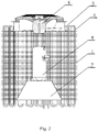
- fig. 2 shows the heat exchanger in a schematic longitudinal section
- fig. 3 shows a variant of the heat exchanger
- fig. 4 shows a cross section of the variant of the exchanger in fig. 3
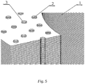
- fig. 5 shows a piece of annular fins
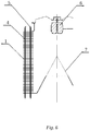
- fig. 6 shows a simplified schematic cross section of the exchanger with a conical diffuser.
- the heat exchanger contains a number of annular fins 1 arranged one above the other with holes 2 having basically the same turn ups 3 which constitute the spacers of annular fins 1 vertical tubes go through the holes 4 over the lower and upper annular fins 1 and nearby protruding tube ends 4 are grouped in pairs with the aid of U-shaped tubes 5 with the exception of one pair acting as an inlet and outlet for fluid flow.
- an axial fan installed 6
- a conical diffuser installed 7 allowing for an equal air flow between successive annular fins 1 .
- a diffuser 7 has the shape of a truncated cone and a mounted compressor 8 .
- the example presented in fig. 1 and fig. 4 annular fins 1 are in the form of a continuous strips coined into a spiral.
Landscapes
- Engineering & Computer Science (AREA)
- Mechanical Engineering (AREA)
- General Engineering & Computer Science (AREA)
- Physics & Mathematics (AREA)
- Thermal Sciences (AREA)
- Chemical & Material Sciences (AREA)
- Combustion & Propulsion (AREA)
- Geometry (AREA)
- Heat-Exchange Devices With Radiators And Conduit Assemblies (AREA)
Abstract
The cylindrical air-cooled heat exchanger characterised in that it contains a number of annular fins ( 1 ) in the form of disks arranged one above the other with holes ( 2 ) having basically the same turn ups ( 3 ) which constitute the spacers of annular fins ( 1 ) and vertical tubes ( 2 ) go through the holes ( 4 ) over the bottom and top fins ( 1 ) and the nearby protruding ends are grouped in pairs with the aid of U-shaped tubes (5) with exception of at least one pair acting as an inlet and outlet for fluid flow and on one side of the formed by the annular fins ( 1 ) roller a radial or axial fan is mounted ( 6 ), and on the opposite side a conical diffuser ( 7 ) is fitted ensuring an equal air flow between successive annular fins ( 1 ).
Description
- The subject of the invention is an air-cooled heat exchanger applicable, in particular, to heating and ventilation systems, air conditioning, cooling, cooling or heating fluids, condensation or evaporation of gases. In more detail, the subject of the invention is a cylindrical heat exchanger with fan - forced draft, including a set of tubes forming a media distribution system, equipped with finned disks for heat transfer.
- Known from the Polish Patent Specification No
107 792 - Air-water mechanical draft cooling tower described for the Polish Patent No
206 746 - Known from the description for the Polish Patent Application No
P-288148 - The Patent Application Publication
US20160290730A1 discloses a tubular heat exchanger with at least two longitudinally extending shell sections each containing a series of fins to which the tube elements adhere. The fan provides airflow across the sections, thus intensifies the heat exchange. - The aim of the invention is the construction of the heat exchanger allowing for improving and intensifying heat exchange and at the same time taking up less space. This invention may be used as a cooler or heater of fluids, a condenser or an evaporator of gases, for example refrigerants.
- The point of the invention is that it contains a number of annular fins in the form of disks arranged one above the other and provided with holes with basically the same turn ups. They serve as spacers of annular fins. Vertical tubes extending over the bottom and upper fins go through the holes. Near the fins there are protruding ends that are grouped in pairs with the aid of U-shaped tubes with the exception of at least one pair acting as an inlet and outlet for fluid flow. On one side of the roller formed by annular fins there is an axial or radial fan mounted whereas on the opposite side there is a conical diffuser allowing for an equal air flow between successive annular fins.
- Favourably, the diffuser is of the shape of a truncated cone and on its upper base a compressor is mounted.
- Favourably, annular fins are in the form of a continuous strip coiled into a spiral.
- This design ensures a significant improvement in heat exchange. The turn ups being the spacers of annular fins come into contact directly with vertical tubes. This way the surface of the thermal energy exchange expands several times and thus it takes less time to cool a medium flowing in the tubes. This allows for a significant reduction in the size of the device and considerable savings of energy required to drive the fans.
- The invention is illustrated in the following drawings of performance, without restrain in any way, in which
figure 1 shows the heat exchanger in a perspective view,fig. 2 shows the heat exchanger in a schematic longitudinal section,fig. 3 shows a variant of the heat exchanger,fig. 4 shows a cross section of the variant of the exchanger infig. 3 ,fig. 5 shows a piece of annular fins,fig. 6 shows a simplified schematic cross section of the exchanger with a conical diffuser. - According to the invention, the heat exchanger contains a number of
annular fins 1 arranged one above the other withholes 2 having basically thesame turn ups 3 which constitute the spacers ofannular fins 1 vertical tubes go through theholes 4 over the lower and upperannular fins 1 and nearby protrudingtube ends 4 are grouped in pairs with the aid ofU-shaped tubes 5 with the exception of one pair acting as an inlet and outlet for fluid flow. Inside, at the top of the formed by theannular fins 1 roller there is an axial fan installed 6 , In the lower part there is a conical diffuser installed 7 allowing for an equal air flow between successiveannular fins 1 . - The example presented in
fig. 2 adiffuser 7 has the shape of a truncated cone and a mountedcompressor 8 . The example presented infig. 1 andfig. 4 annular fins 1 are in the form of a continuous strips coined into a spiral.
Claims (3)
- The cylindrical air-cooled heat exchanger characterised in that it contains a number of annular fins (1) in the form of disks arranged one above the other with holes (2) having basically the same turn ups (3) which constitute the spacers of annular fins (1) and vertical tubes (2) go through the holes (4) over the bottom and top fins (1) and the nearby protruding ends are grouped in pairs with the aid of U-shaped tubes (5) with exception of at least one pair acting as an inlet and outlet for fluid flow and on one side of the formed by the annular fins (1) roller a radial or axial fan is mounted (6), and on the opposite side a conical diffuser (7) is fitted ensuring an equal air flow between successive annular fins (1).
- A cylindrical exchanger according to the claim 1 characterised in that a diffuser (7) is in the form of a truncated cone and on its upper base a compressor is installed (8).
- A cylindrical exchanger according to the claim 1 characterised in that its annular fins (1) are in the form of a continuous strip coined into a spiral.
Priority Applications (1)
| Application Number | Priority Date | Filing Date | Title |
|---|---|---|---|
| EP17020231.1A EP3410053A1 (en) | 2017-05-30 | 2017-05-30 | Air-cooled heat exchanger |
Applications Claiming Priority (1)
| Application Number | Priority Date | Filing Date | Title |
|---|---|---|---|
| EP17020231.1A EP3410053A1 (en) | 2017-05-30 | 2017-05-30 | Air-cooled heat exchanger |
Publications (1)
| Publication Number | Publication Date |
|---|---|
| EP3410053A1 true EP3410053A1 (en) | 2018-12-05 |
Family
ID=59101254
Family Applications (1)
| Application Number | Title | Priority Date | Filing Date |
|---|---|---|---|
| EP17020231.1A Withdrawn EP3410053A1 (en) | 2017-05-30 | 2017-05-30 | Air-cooled heat exchanger |
Country Status (1)
| Country | Link |
|---|---|
| EP (1) | EP3410053A1 (en) |
Cited By (7)
| Publication number | Priority date | Publication date | Assignee | Title |
|---|---|---|---|---|
| CN109945717A (en) * | 2019-03-25 | 2019-06-28 | 中国空气动力研究与发展中心超高速空气动力研究所 | A kind of high-temperature cooler set of heat exchange tubes |
| CN110056952A (en) * | 2019-05-05 | 2019-07-26 | 青岛海尔空调器有限总公司 | A kind of exhaust apparatus, air conditioner indoor unit and air-conditioning |
| CN110671924A (en) * | 2019-10-30 | 2020-01-10 | 珠海格力电器股份有限公司 | Air duct structure, dryer with air duct structure and control method of dryer |
| CN110887387A (en) * | 2019-11-21 | 2020-03-17 | 新乡航空工业(集团)有限公司 | Novel air-fuel annular heat exchanger for aeroengine |
| EP3926280A1 (en) * | 2020-06-17 | 2021-12-22 | Robert Bosch GmbH | Heat exchanger unit |
| CN116734511A (en) * | 2023-05-10 | 2023-09-12 | 青岛海尔空调器有限总公司 | Heat exchanger and air conditioner indoor unit with same |
| CN116734510A (en) * | 2023-05-10 | 2023-09-12 | 青岛海尔空调器有限总公司 | Heat exchanger and air conditioner indoor unit with same |
Citations (12)
| Publication number | Priority date | Publication date | Assignee | Title |
|---|---|---|---|---|
| US2630691A (en) * | 1951-11-20 | 1953-03-10 | Int Harvester Co | Dehumidifying air-conditioning apparatus |
| US3173479A (en) * | 1959-09-30 | 1965-03-16 | Olin Mathieson | Heat exchanger |
| PL107792B1 (en) | 1977-11-23 | 1980-03-31 | Politechnika Wroclawska | Fan type air-water cooler |
| PL288148A1 (en) | 1990-12-06 | 1991-07-15 | Huta Katowice Kom Metalurgiczn | Layered heat exhanger |
| KR20010001517U (en) * | 1999-06-29 | 2001-01-15 | 윤종용 | Outdoor unit of an Air conditioner having cylinderical shape |
| EP1519645A2 (en) * | 2003-09-25 | 2005-03-30 | Hitachi, Ltd. | Liquid cooling module |
| KR20060011468A (en) * | 2004-07-30 | 2006-02-03 | 삼성전자주식회사 | Air conditioner |
| US20100097763A1 (en) * | 2008-10-20 | 2010-04-22 | Fu Zhun Precision Industry (Shen Zhen) Co., Ltd. | Heat dissipation device |
| PL206746B1 (en) | 2004-06-25 | 2010-09-30 | Politechnika Wroclawska | Water cooling stack with air forcing fan |
| US20130043007A1 (en) * | 2011-08-17 | 2013-02-21 | Joung-Wen HONG | Condenser with capillary cooling device |
| US20130333410A1 (en) * | 2010-10-27 | 2013-12-19 | Namjoon Cho | Air conditioner |
| US20160290730A1 (en) | 2013-11-25 | 2016-10-06 | Carrier Corporation | Dual duty microchannel heat exchanger |
-
2017
- 2017-05-30 EP EP17020231.1A patent/EP3410053A1/en not_active Withdrawn
Patent Citations (12)
| Publication number | Priority date | Publication date | Assignee | Title |
|---|---|---|---|---|
| US2630691A (en) * | 1951-11-20 | 1953-03-10 | Int Harvester Co | Dehumidifying air-conditioning apparatus |
| US3173479A (en) * | 1959-09-30 | 1965-03-16 | Olin Mathieson | Heat exchanger |
| PL107792B1 (en) | 1977-11-23 | 1980-03-31 | Politechnika Wroclawska | Fan type air-water cooler |
| PL288148A1 (en) | 1990-12-06 | 1991-07-15 | Huta Katowice Kom Metalurgiczn | Layered heat exhanger |
| KR20010001517U (en) * | 1999-06-29 | 2001-01-15 | 윤종용 | Outdoor unit of an Air conditioner having cylinderical shape |
| EP1519645A2 (en) * | 2003-09-25 | 2005-03-30 | Hitachi, Ltd. | Liquid cooling module |
| PL206746B1 (en) | 2004-06-25 | 2010-09-30 | Politechnika Wroclawska | Water cooling stack with air forcing fan |
| KR20060011468A (en) * | 2004-07-30 | 2006-02-03 | 삼성전자주식회사 | Air conditioner |
| US20100097763A1 (en) * | 2008-10-20 | 2010-04-22 | Fu Zhun Precision Industry (Shen Zhen) Co., Ltd. | Heat dissipation device |
| US20130333410A1 (en) * | 2010-10-27 | 2013-12-19 | Namjoon Cho | Air conditioner |
| US20130043007A1 (en) * | 2011-08-17 | 2013-02-21 | Joung-Wen HONG | Condenser with capillary cooling device |
| US20160290730A1 (en) | 2013-11-25 | 2016-10-06 | Carrier Corporation | Dual duty microchannel heat exchanger |
Cited By (11)
| Publication number | Priority date | Publication date | Assignee | Title |
|---|---|---|---|---|
| CN109945717A (en) * | 2019-03-25 | 2019-06-28 | 中国空气动力研究与发展中心超高速空气动力研究所 | A kind of high-temperature cooler set of heat exchange tubes |
| CN110056952A (en) * | 2019-05-05 | 2019-07-26 | 青岛海尔空调器有限总公司 | A kind of exhaust apparatus, air conditioner indoor unit and air-conditioning |
| CN110056952B (en) * | 2019-05-05 | 2021-12-21 | 重庆海尔空调器有限公司 | Air outlet device, air conditioner indoor unit and air conditioner |
| CN110671924A (en) * | 2019-10-30 | 2020-01-10 | 珠海格力电器股份有限公司 | Air duct structure, dryer with air duct structure and control method of dryer |
| CN110671924B (en) * | 2019-10-30 | 2023-07-11 | 珠海格力电器股份有限公司 | Air duct structure, dryer with air duct structure and dryer control method |
| CN110887387A (en) * | 2019-11-21 | 2020-03-17 | 新乡航空工业(集团)有限公司 | Novel air-fuel annular heat exchanger for aeroengine |
| CN110887387B (en) * | 2019-11-21 | 2021-06-08 | 新乡航空工业(集团)有限公司 | Air-fuel annular heat exchanger for aircraft engine |
| EP3926280A1 (en) * | 2020-06-17 | 2021-12-22 | Robert Bosch GmbH | Heat exchanger unit |
| CN116734511A (en) * | 2023-05-10 | 2023-09-12 | 青岛海尔空调器有限总公司 | Heat exchanger and air conditioner indoor unit with same |
| CN116734510A (en) * | 2023-05-10 | 2023-09-12 | 青岛海尔空调器有限总公司 | Heat exchanger and air conditioner indoor unit with same |
| CN116734510B (en) * | 2023-05-10 | 2025-11-18 | 青岛海尔空调器有限总公司 | Heat exchanger and indoor air conditioning unit having the heat exchanger |
Similar Documents
| Publication | Publication Date | Title |
|---|---|---|
| EP3410053A1 (en) | Air-cooled heat exchanger | |
| EP2762820B1 (en) | Air conditioner and heat exchanger therefor | |
| US11162741B2 (en) | Heat exchanger with louvered fins | |
| CN106338162A (en) | Microchannel heat exchanger and application of same in system | |
| US11333451B2 (en) | Plate and shell heat exchanging system having a divided manifold tube | |
| EP1971815B1 (en) | Spirally wound, layered tube heat exchanger | |
| US10495383B2 (en) | Wound layered tube heat exchanger | |
| CN110762609B (en) | Air conditioner indoor unit, air conditioner | |
| EP2685195A2 (en) | Heat exchanger | |
| EP3358271B1 (en) | Water heater and a pipe coil for a heat exchanger, in particular an exchanger intended for that specific water heater | |
| KR101661954B1 (en) | Heat exchanger | |
| CN202149582U (en) | Air conditioner and dry-type surface cooler thereof | |
| US10386124B2 (en) | Dual pass opposed (reverse) flow cooling coil with improved performance | |
| RU201175U1 (en) | Air cooling heat exchanger | |
| CN213955448U (en) | Evaporation system of vertical indoor unit | |
| US7913512B2 (en) | Air-heated heat exchanger | |
| CN102901202A (en) | Air conditioner and dry-type surface cooler thereof | |
| KR101679575B1 (en) | Heat exchanger | |
| CN116601448A (en) | Evaporative wet surface air cooler | |
| JP2000227230A (en) | Heat exchange coil for air conditioner | |
| CN111750572B (en) | Condensers and air conditioning equipment | |
| CN119737703A (en) | Condenser of refrigeration range hood and refrigeration range hood | |
| KR19990032447U (en) | Heat exchanger to increase the turbulence of the heat medium | |
| CN104567447A (en) | Reciprocal steam admission composite condensing and cooling device for finned tube bundles | |
| CN112781106A (en) | Evaporating system of vertical cabinet type indoor unit |
Legal Events
| Date | Code | Title | Description |
|---|---|---|---|
| PUAI | Public reference made under article 153(3) epc to a published international application that has entered the european phase |
Free format text: ORIGINAL CODE: 0009012 |
|
| AK | Designated contracting states |
Kind code of ref document: A1 Designated state(s): AL AT BE BG CH CY CZ DE DK EE ES FI FR GB GR HR HU IE IS IT LI LT LU LV MC MK MT NL NO PL PT RO RS SE SI SK SM TR |
|
| AX | Request for extension of the european patent |
Extension state: BA ME |
|
| STAA | Information on the status of an ep patent application or granted ep patent |
Free format text: STATUS: THE APPLICATION IS DEEMED TO BE WITHDRAWN |
|
| 18D | Application deemed to be withdrawn |
Effective date: 20190606 |