EP3410011A1 - Gas burner assembly, preferably for a gas cooking hob - Google Patents
Gas burner assembly, preferably for a gas cooking hob Download PDFInfo
- Publication number
- EP3410011A1 EP3410011A1 EP17173312.4A EP17173312A EP3410011A1 EP 3410011 A1 EP3410011 A1 EP 3410011A1 EP 17173312 A EP17173312 A EP 17173312A EP 3410011 A1 EP3410011 A1 EP 3410011A1
- Authority
- EP
- European Patent Office
- Prior art keywords
- gas
- burner assembly
- gas burner
- burner
- assembly according
- Prior art date
- Legal status (The legal status is an assumption and is not a legal conclusion. Google has not performed a legal analysis and makes no representation as to the accuracy of the status listed.)
- Withdrawn
Links
Images

Classifications
-
- F—MECHANICAL ENGINEERING; LIGHTING; HEATING; WEAPONS; BLASTING
- F23—COMBUSTION APPARATUS; COMBUSTION PROCESSES
- F23D—BURNERS
- F23D14/00—Burners for combustion of a gas, e.g. of a gas stored under pressure as a liquid
- F23D14/02—Premix gas burners, i.e. in which gaseous fuel is mixed with combustion air upstream of the combustion zone
- F23D14/04—Premix gas burners, i.e. in which gaseous fuel is mixed with combustion air upstream of the combustion zone induction type, e.g. Bunsen burner
- F23D14/06—Premix gas burners, i.e. in which gaseous fuel is mixed with combustion air upstream of the combustion zone induction type, e.g. Bunsen burner with radial outlets at the burner head
-
- F—MECHANICAL ENGINEERING; LIGHTING; HEATING; WEAPONS; BLASTING
- F23—COMBUSTION APPARATUS; COMBUSTION PROCESSES
- F23D—BURNERS
- F23D14/00—Burners for combustion of a gas, e.g. of a gas stored under pressure as a liquid
- F23D14/46—Details
- F23D14/48—Nozzles
- F23D14/58—Nozzles characterised by the shape or arrangement of the outlet or outlets from the nozzle, e.g. of annular configuration
Definitions
- the present invention relates to a gas burner assembly.
- the gas burner assembly is provided for a gas cooking hob.
- the present invention relates to a gas cooking hob, in particular for a domestic appliance.
- the gas burner includes main flame ports and secondary flame ports.
- Said main flame port is high and narrow and generates a main flame for transferring the heat.
- the secondary flame port is arranged close to the main flame port and is smaller than said main flame port.
- the secondary flame port is provided for stabilising the main flame.
- the main flame port with the secondary flame port is usually formed on aluminium burner crowns.
- the main flame port has the shape of a hole, wherein above or beneath a pilot flame is generated for stabilising the main flame. The latter is often used at brass flame spreaders.
- the main flame for transferring the heat and the secondary flame for stabilising the speed and combustion of main flame.
- the object is achieved by the gas burner assembly according to claim 1.
- a gas burner assembly preferably for a gas cooking hob, is provided, wherein:
- the main idea of the present invention is the shape of the flame ports.
- the cross-section of the flame port extends perpendicular to the flow direction of the air-gas mixture.
- the cross-section of the spoon is relative flat.
- the inventive flame ports result in flame shapes, which optimise the heat transfer. No secondary flames are required in order to stabilise the main flames.
- the gas is completely used for heating a subject above the gas burner assembly. Further, the inventive flame ports are easy to clean.
- the width of the flame port is between 2 mm and 6 mm, preferably between 3 mm and 5 mm, in particular 4 mm.
- the height of the flame port is between 1 mm and 3 mm, preferably between 1.5 mm and 2.5 mm, in particular 2 mm.
- the ratio between the width and the height of the flame port may be between one and three.
- each flame port is formed on the top side of the side wall of the burner crown element, while the top wall of each flame port is provided by the burner cap.
- the lateral walls of the flame port are inclined, wherein the width of said flame port increases from the bottom up.
- the transition from the lateral wall to the bottom wall of the flame port may be smooth and without any edges.
- the bottom wall of the flame ports may be convex.
- the burner crown element includes a base plate, wherein preferably the base plate is formed as a circular or elliptic disk.
- the side wall of the burner crown element extends upwards from said base plate along a circular or elliptic path.
- the side wall of the burner crown element may take course along an arbitrary path.
- an opening for supplying a gas-air mixture is formed in the centre of the base plate.
- the base plate may be convex, wherein the height in the centre of the inner space of gas burner assembly is lower than the height in an outer portion of said inner space, so that a Venturi effect is achieved.
- the burner crown element is formed as single-piece part.
- the burner cap is made of steel, cast iron or brass.
- the present invention relates to a gas cooking hob, in particular for a domestic appliance, wherein the gas cooking hob comprises at least one gas burner assembly mentioned above.
- FIG 1 illustrates a schematic exploded perspective view of a gas burner assembly 10 according to a preferred embodiment of the present invention.
- the gas burner assembly 10 is provided for a gas cooking hob.
- the gas burner assembly 10 comprises a burner cap 12 and a burner crown element 14.
- the burner cap is made of steel, cast iron or brass.
- the burner crown element 14 includes a base plate 16 and a side wall 18.
- the base plate 16 is substantially formed as a circular disk.
- the side wall 18 extends upwards from said base plate 16 along a circular path.
- the burner crown element 14 is formed as a single-piece part.
- An inner space of the gas burner assembly 10 is limited by the burner cap 12, the base plate 16 and the side wall 18.
- An opening 22 is formed in the centre of the base plate 16. Said opening 22 is provided for introducing a gas-air mixture into the inner space of the gas burner assembly 10.
- a plurality of flame ports 20 is formed on the top side of the side wall 18 of the burner crown element 14.
- Each flame port 20 has a shape similar to a spoon.
- the lateral walls and the bottom wall of each flame port 20 are formed on the top side of the side wall 18 of the burner crown element 14.
- the top wall of each flame port 20 is provided by the burner cap 12.
- the cross-section of the flame port 20 is relative flat.
- the cross-section of the flame port 20 extends perpendicular to the flow direction of the air-gas mixture leaving the inner space of the gas burner assembly 10.
- the cross-section of the flame port 20 is similar to the cross-section of a spoon.
- the width w of the flame port 20 is between 2 mm and 6 mm, preferably between 3 mm and 5 mm. In particular, the width w of the flame port 20 is about 4 mm.
- the height h of the flame port 20 is between 1 mm and 3 mm, preferably between 1.5 mm and 2.5 mm. In particular, the height h of the flame port 20 is about 2 mm.
- the flame ports 20 result in flame shapes, which optimise the heat transfer. No secondary flames are required in order to stabilise the main flames. In this way, the gas is completely used for heating a cooking vessel above the gas burner assembly 10. Further, the flame ports 20 are easy to clean.
- the base plate 16 of the burner crown element 14 is convex, so that the height in the centre of the inner space of gas burner assembly 10 is lower than the height in the outer portion of said inner space. This results in a Venturi effect.
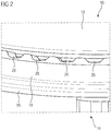
- FIG 2 illustrates a schematic detailed perspective view of the gas burner assembly 10 according to the preferred embodiment of the present invention.
- FIG 2 clarifies the shapes of the flame ports 20.
- the lateral walls of the flame ports 20 are inclined, so that the width of the flame ports 20 increases from the bottom up.
- the bottom wall of the flame ports 20 is marginally convex.
- the transition from the lateral wall to the bottom wall is smooth and without any sharp edges.
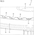
- FIG 3 illustrates a schematic detailed perspective view of a burner crown element 14 for the gas burner assembly 10 according to the preferred embodiment of the present invention.
- FIG 3 clarifies the flat structure of the flame ports 20.
- the cross-section of the flame port 20 is similar to the cross-section of a spoon.
- the width w of the flame port 20 is between 2 mm and 6 mm, preferably between 3 mm and 5 mm. In particular, the width w of the flame port 20 is about 4 mm.
- the height h of the flame port 20 is between 1 mm and 3 mm, preferably between 1.5 mm and 2.5 mm. In particular, the height h of the flame port 20 is about 2 mm.
- the ratio between the width and the height of the flame port 20 is between one and three.
- the transition between the lateral wall to the bottom wall of the flame ports is smooth and without any sharp edges.
- the lateral walls of the flame ports 20 are inclined, so that the width of the flame ports 20 increases from the bottom up.
- the bottom wall of the flame ports 20 is marginally convex.
- the flame ports 20 according to the present invention result in flame shapes, which optimise the heat transfer. No secondary flames are required in order to stabilise the main flames.
- the gas is completely used for heating a cooking vessel above the gas burner assembly 10. In particular, the flame ports 20 are easy to clean.
Landscapes
- Engineering & Computer Science (AREA)
- Chemical & Material Sciences (AREA)
- Combustion & Propulsion (AREA)
- Mechanical Engineering (AREA)
- General Engineering & Computer Science (AREA)
- Gas Burners (AREA)
Abstract
The present invention relates to a gas burner assembly (10), preferably for a gas cooking hob. The gas burner assembly (10) comprises a burner cap (12) and a burner crown element (14). The burner cap (12) is adapted for covering the burner crown element (14). The burner crown element (14) includes a side wall (18) enclosing an inner space of the gas burner assembly (10). The burner cap (12) is arranged above the side wall (18) of the burner crown element (14). A plurality of flame ports (20) is formed on the top side of the side wall (18). The cross-section of the flame port (20) is formed as the cross-section of a spoon.
Description
- The present invention relates to a gas burner assembly. Preferably, the gas burner assembly is provided for a gas cooking hob. Further, the present invention relates to a gas cooking hob, in particular for a domestic appliance.
- Many various types of gas burners exist. There are different technologies for supplying a gas-air mixture to a flame spreader or burner crown. A plurality of flame ports is usually arranged in the circumference of said flame spreader or burner crown. For example, the gas burner includes main flame ports and secondary flame ports. Said main flame port is high and narrow and generates a main flame for transferring the heat. The secondary flame port is arranged close to the main flame port and is smaller than said main flame port. The secondary flame port is provided for stabilising the main flame. The main flame port with the secondary flame port is usually formed on aluminium burner crowns. According to another example, the main flame port has the shape of a hole, wherein above or beneath a pilot flame is generated for stabilising the main flame. The latter is often used at brass flame spreaders. There are further concepts with the main flame for transferring the heat and the secondary flame for stabilising the speed and combustion of main flame.
- It is an object of the present invention to provide a gas burner assembly, which allows an improved heat transfer and an improved cleanability of said gas burner assembly by low complexity.
- The object is achieved by the gas burner assembly according to claim 1.
- According to the present invention a gas burner assembly, preferably for a gas cooking hob, is provided, wherein:
- the gas burner assembly comprises a burner cap and a burner crown element,
- the burner cap is adapted for covering the burner crown element,
- the burner crown element includes a side wall enclosing an inner space of the gas burner assembly,
- the burner cap is arranged above the side wall of the burner crown element,
- a plurality of flame ports is formed on the top side of the side wall, and
- the cross-section of the flame ports is formed as the cross-section of a spoon.
- The main idea of the present invention is the shape of the flame ports. The cross-section of the flame port extends perpendicular to the flow direction of the air-gas mixture. The cross-section of the spoon is relative flat. The inventive flame ports result in flame shapes, which optimise the heat transfer. No secondary flames are required in order to stabilise the main flames. The gas is completely used for heating a subject above the gas burner assembly. Further, the inventive flame ports are easy to clean.
- For example, the width of the flame port is between 2 mm and 6 mm, preferably between 3 mm and 5 mm, in particular 4 mm.
- For instance, the height of the flame port is between 1 mm and 3 mm, preferably between 1.5 mm and 2.5 mm, in particular 2 mm.
- Further, the ratio between the width and the height of the flame port may be between one and three.
- In particular, the lateral walls and the bottom wall of each flame port are formed on the top side of the side wall of the burner crown element, while the top wall of each flame port is provided by the burner cap.
- Preferably, the lateral walls of the flame port are inclined, wherein the width of said flame port increases from the bottom up.
- Moreover, the transition from the lateral wall to the bottom wall of the flame port may be smooth and without any edges.
- Additionally, the bottom wall of the flame ports may be convex.
- Further, the burner crown element includes a base plate, wherein preferably the base plate is formed as a circular or elliptic disk.
- In particular, the side wall of the burner crown element extends upwards from said base plate along a circular or elliptic path. In general, the side wall of the burner crown element may take course along an arbitrary path.
- For example, an opening for supplying a gas-air mixture is formed in the centre of the base plate.
- Additionally, the base plate may be convex, wherein the height in the centre of the inner space of gas burner assembly is lower than the height in an outer portion of said inner space, so that a Venturi effect is achieved.
- Preferably, the burner crown element is formed as single-piece part.
- For instance, the burner cap is made of steel, cast iron or brass.
- At last, the present invention relates to a gas cooking hob, in particular for a domestic appliance, wherein the gas cooking hob comprises at least one gas burner assembly mentioned above.
- Novel and inventive features of the present invention are set forth in the appended claims.
- The present invention will be described in further detail with reference to the drawings, in which
- FIG 1
- illustrates a schematic exploded perspective view of a gas burner assembly according to a preferred embodiment of the present invention,
- FIG 2
- illustrates a schematic detailed perspective view of the gas burner assembly according to the preferred embodiment of the present invention, and
- FIG 3
- illustrates a schematic detailed perspective view of a burner crown element for the gas burner assembly according to the preferred embodiment of the present invention.
-
FIG 1 illustrates a schematic exploded perspective view of agas burner assembly 10 according to a preferred embodiment of the present invention. In this example, thegas burner assembly 10 is provided for a gas cooking hob. - The
gas burner assembly 10 comprises aburner cap 12 and aburner crown element 14. Preferably, the burner cap is made of steel, cast iron or brass. Theburner crown element 14 includes abase plate 16 and aside wall 18. Thebase plate 16 is substantially formed as a circular disk. Theside wall 18 extends upwards fromsaid base plate 16 along a circular path. Theburner crown element 14 is formed as a single-piece part. An inner space of thegas burner assembly 10 is limited by theburner cap 12, thebase plate 16 and theside wall 18. Anopening 22 is formed in the centre of thebase plate 16. Said opening 22 is provided for introducing a gas-air mixture into the inner space of thegas burner assembly 10. - A plurality of
flame ports 20 is formed on the top side of theside wall 18 of theburner crown element 14. Eachflame port 20 has a shape similar to a spoon. The lateral walls and the bottom wall of eachflame port 20 are formed on the top side of theside wall 18 of theburner crown element 14. The top wall of eachflame port 20 is provided by theburner cap 12. - The cross-section of the
flame port 20 is relative flat. The cross-section of theflame port 20 extends perpendicular to the flow direction of the air-gas mixture leaving the inner space of thegas burner assembly 10. The cross-section of theflame port 20 is similar to the cross-section of a spoon. The width w of theflame port 20 is between 2 mm and 6 mm, preferably between 3 mm and 5 mm. In particular, the width w of theflame port 20 is about 4 mm. The height h of theflame port 20 is between 1 mm and 3 mm, preferably between 1.5 mm and 2.5 mm. In particular, the height h of theflame port 20 is about 2 mm. - The
flame ports 20 result in flame shapes, which optimise the heat transfer. No secondary flames are required in order to stabilise the main flames. In this way, the gas is completely used for heating a cooking vessel above thegas burner assembly 10. Further, theflame ports 20 are easy to clean. - Moreover, the
base plate 16 of theburner crown element 14 is convex, so that the height in the centre of the inner space ofgas burner assembly 10 is lower than the height in the outer portion of said inner space. This results in a Venturi effect. -
FIG 2 illustrates a schematic detailed perspective view of thegas burner assembly 10 according to the preferred embodiment of the present invention.FIG 2 clarifies the shapes of theflame ports 20. - The lateral walls of the
flame ports 20 are inclined, so that the width of theflame ports 20 increases from the bottom up. The bottom wall of theflame ports 20 is marginally convex. The transition from the lateral wall to the bottom wall is smooth and without any sharp edges. -
FIG 3 illustrates a schematic detailed perspective view of aburner crown element 14 for thegas burner assembly 10 according to the preferred embodiment of the present invention.FIG 3 clarifies the flat structure of theflame ports 20. - The cross-section of the
flame port 20 is similar to the cross-section of a spoon. The width w of theflame port 20 is between 2 mm and 6 mm, preferably between 3 mm and 5 mm. In particular, the width w of theflame port 20 is about 4 mm. The height h of theflame port 20 is between 1 mm and 3 mm, preferably between 1.5 mm and 2.5 mm. In particular, the height h of theflame port 20 is about 2 mm. The ratio between the width and the height of theflame port 20 is between one and three. - The transition between the lateral wall to the bottom wall of the flame ports is smooth and without any sharp edges. The lateral walls of the
flame ports 20 are inclined, so that the width of theflame ports 20 increases from the bottom up. The bottom wall of theflame ports 20 is marginally convex. - The
flame ports 20 according to the present invention result in flame shapes, which optimise the heat transfer. No secondary flames are required in order to stabilise the main flames. The gas is completely used for heating a cooking vessel above thegas burner assembly 10. In particular, theflame ports 20 are easy to clean. - Although an illustrative embodiment of the present invention has been described herein with reference to the accompanying drawings, it is to be understood that the present invention is not limited to that precise embodiment, and that various other changes and modifications may be affected therein by one skilled in the art without departing from the scope or spirit of the invention. All such changes and modifications are intended to be included within the scope of the invention as defined by the appended claims.
-
- 10
- gas burner assembly
- 12
- burner cap
- 14
- burner crown element
- 16
- base plate
- 18
- side wall
- 20
- flame port
- 22
- opening
- h
- height of the flame port
- w
- width of the flame port
Claims (15)
- A gas burner assembly (10), preferably for a gas cooking hob, wherein:- the gas burner assembly (10) comprises a burner cap (12) and a burner crown element (14),- the burner cap (12) is adapted for covering the burner crown element (14),- the burner crown element (14) includes a side wall (18) enclosing an inner space of the gas burner assembly (10),- the burner cap (12) is arranged above the side wall (18) of the burner crown element (14),- a plurality of flame ports (20) is formed on the top side of the side wall (18), and- the cross-section of the flame port (20) is formed as the cross-section of a spoon.
- The gas burner assembly according to claim 1,
characterised in that
the width of the flame port (20) is between 2 mm and 6 mm, preferably between 3 mm and 5 mm, in particular 4 mm. - The gas burner assembly according to claim 1 or 2,
characterised in that
the height of the flame port (20) is between 1 mm and 3 mm, preferably between 1.5 mm and 2.5 mm, in particular 2 mm. - The gas burner assembly according to any one of the preceding claims,
characterised in that
the ratio between the width and the height of the flame port (20) is between one and three. - The gas burner assembly according to any one of the preceding claims,
characterised in that
the lateral walls and the bottom wall of each flame port (20) are formed on the top side of the side wall (18) of the burner crown element (14), while the top wall of each flame port (20) is provided by the burner cap (12). - The gas burner assembly according to any one of the preceding claims,
characterised in that
the lateral walls of the flame port (20) are inclined, wherein the width of said flame port (20) increases from the bottom up. - The gas burner assembly according to any one of the preceding claims,
characterised in that
the transition from the lateral wall to the bottom wall of the flame port (20) is smooth and without any edges. - The gas burner assembly according to any one of the preceding claims,
characterised in that
the bottom wall of the flame ports (20) is convex. - The gas burner assembly according to any one of the preceding claims,
characterised in that
the burner crown element (14) includes a base plate (16), wherein preferably the base plate (16) is formed as a circular or elliptic disk. - The gas burner assembly according to claim 9,
characterised in that
the side wall (18) of the burner crown element (14) extends upwards from said base plate (16) along a circular or elliptic path. - The gas burner assembly according to claim 9 or 10,
characterised in that
an opening (22) for supplying a gas-air mixture is formed in the centre of the base plate (16). - The gas burner assembly according to claim 11,
characterised in that
the base plate (16) is convex, wherein the height in the centre of the inner space of gas burner assembly (10) is lower than the height in an outer portion of said inner space, so that a Venturi effect is achieved. - The gas burner assembly according to any one of the preceding claims,
characterised in that
the burner crown element (14) is formed as single-piece part. - The gas burner assembly according to any one of the preceding claims,
characterised in that
the burner cap (12) is made of steel, cast iron or brass. - A gas cooking hob, in particular for a domestic appliance, characterised in that
the gas cooking hob comprises at least one gas burner assembly (10) according to any one of the preceding claims.
Priority Applications (1)
| Application Number | Priority Date | Filing Date | Title |
|---|---|---|---|
| EP17173312.4A EP3410011A1 (en) | 2017-05-29 | 2017-05-29 | Gas burner assembly, preferably for a gas cooking hob |
Applications Claiming Priority (1)
| Application Number | Priority Date | Filing Date | Title |
|---|---|---|---|
| EP17173312.4A EP3410011A1 (en) | 2017-05-29 | 2017-05-29 | Gas burner assembly, preferably for a gas cooking hob |
Publications (1)
| Publication Number | Publication Date |
|---|---|
| EP3410011A1 true EP3410011A1 (en) | 2018-12-05 |
Family
ID=58779034
Family Applications (1)
| Application Number | Title | Priority Date | Filing Date |
|---|---|---|---|
| EP17173312.4A Withdrawn EP3410011A1 (en) | 2017-05-29 | 2017-05-29 | Gas burner assembly, preferably for a gas cooking hob |
Country Status (1)
| Country | Link |
|---|---|
| EP (1) | EP3410011A1 (en) |
Cited By (1)
| Publication number | Priority date | Publication date | Assignee | Title |
|---|---|---|---|---|
| US11421890B2 (en) | 2020-12-08 | 2022-08-23 | Whirlpool Corporation | Burner cap for a burner assembly |
Citations (5)
| Publication number | Priority date | Publication date | Assignee | Title |
|---|---|---|---|---|
| US873182A (en) * | 1907-03-12 | 1907-12-10 | Edward S Springer | Gas-burner. |
| US5335646A (en) * | 1993-08-30 | 1994-08-09 | Robertshaw Controls Company | Water heater, a burner unit therefor and methods of making the same |
| WO2002006728A1 (en) * | 2000-07-19 | 2002-01-24 | Fisher & Paykel Appliances Limited | An improved gas burner |
| EP1277013B1 (en) * | 2000-04-28 | 2004-09-29 | Paolo Moresco | Gas burner for a cooking hob |
| WO2013091054A1 (en) * | 2011-12-21 | 2013-06-27 | Whirlpool S.A. | Burner for cooking equipments |
-
2017
- 2017-05-29 EP EP17173312.4A patent/EP3410011A1/en not_active Withdrawn
Patent Citations (5)
| Publication number | Priority date | Publication date | Assignee | Title |
|---|---|---|---|---|
| US873182A (en) * | 1907-03-12 | 1907-12-10 | Edward S Springer | Gas-burner. |
| US5335646A (en) * | 1993-08-30 | 1994-08-09 | Robertshaw Controls Company | Water heater, a burner unit therefor and methods of making the same |
| EP1277013B1 (en) * | 2000-04-28 | 2004-09-29 | Paolo Moresco | Gas burner for a cooking hob |
| WO2002006728A1 (en) * | 2000-07-19 | 2002-01-24 | Fisher & Paykel Appliances Limited | An improved gas burner |
| WO2013091054A1 (en) * | 2011-12-21 | 2013-06-27 | Whirlpool S.A. | Burner for cooking equipments |
Cited By (1)
| Publication number | Priority date | Publication date | Assignee | Title |
|---|---|---|---|---|
| US11421890B2 (en) | 2020-12-08 | 2022-08-23 | Whirlpool Corporation | Burner cap for a burner assembly |
Similar Documents
| Publication | Publication Date | Title |
|---|---|---|
| US7628609B2 (en) | Hub and spoke burner with flame stability | |
| US7527495B2 (en) | Cooperating bridge burner system | |
| US10816215B2 (en) | Diffusion cap burner for gas cooking appliance | |
| EP3002513B1 (en) | Gas burner assembly for a cooking hob | |
| US7017572B2 (en) | Method and apparatus for gas ranges | |
| EP3263986A1 (en) | High efficiency high power inner flame burner | |
| US10663164B2 (en) | Gas burner assembly | |
| EP3299716B1 (en) | Burner for gas apparatus | |
| NO310161B1 (en) | Gas burner for stove | |
| US10646072B2 (en) | Zonal barbecue grill with carryover provision | |
| CN108443883B (en) | Fire covers, burners and gas cooktops | |
| US20180073731A1 (en) | Burner cover and gas burner | |
| CA2934672A1 (en) | Dual ring burner ovni | |
| US11940158B2 (en) | Dual-burner assemblies for cookboxes of gas grills | |
| EP2799771A2 (en) | Gas burning system, in particular for a food cooking appliance | |
| US20180195718A1 (en) | Gas burner assembly for a gas cooking appliance | |
| US10605462B2 (en) | Main top of a cooktop appliance | |
| KR20160064017A (en) | Gas cooking appliance, more particularly a gas oven | |
| KR200476624Y1 (en) | Cooking vessel | |
| TW202022293A (en) | Burner for gas stove and gas stove characterized in that suppressing a mutual interference of flames of the lower burner section (6) and flames of the upper burner portion (5) | |
| CN206890516U (en) | Burner and gas-cooker | |
| WO2019202423A1 (en) | A cooktop with extractor hood | |
| EP3128235A1 (en) | Gas burner, in particular for a cooking top for household use | |
| JP6671233B2 (en) | Stove burner | |
| US20160370012A1 (en) | Burner of Gas Grill |
Legal Events
| Date | Code | Title | Description |
|---|---|---|---|
| PUAI | Public reference made under article 153(3) epc to a published international application that has entered the european phase |
Free format text: ORIGINAL CODE: 0009012 |
|
| AK | Designated contracting states |
Kind code of ref document: A1 Designated state(s): AL AT BE BG CH CY CZ DE DK EE ES FI FR GB GR HR HU IE IS IT LI LT LU LV MC MK MT NL NO PL PT RO RS SE SI SK SM TR |
|
| AX | Request for extension of the european patent |
Extension state: BA ME |
|
| STAA | Information on the status of an ep patent application or granted ep patent |
Free format text: STATUS: THE APPLICATION IS DEEMED TO BE WITHDRAWN |
|
| 18D | Application deemed to be withdrawn |
Effective date: 20190606 |