EP3409980B1 - Valve device and waste heat recovery system - Google Patents
Valve device and waste heat recovery system Download PDFInfo
- Publication number
- EP3409980B1 EP3409980B1 EP17744315.7A EP17744315A EP3409980B1 EP 3409980 B1 EP3409980 B1 EP 3409980B1 EP 17744315 A EP17744315 A EP 17744315A EP 3409980 B1 EP3409980 B1 EP 3409980B1
- Authority
- EP
- European Patent Office
- Prior art keywords
- valve
- passage
- valve shaft
- exhaust gas
- shaft holes
- Prior art date
- Legal status (The legal status is an assumption and is not a legal conclusion. Google has not performed a legal analysis and makes no representation as to the accuracy of the status listed.)
- Active
Links
Images




Classifications
-
- F—MECHANICAL ENGINEERING; LIGHTING; HEATING; WEAPONS; BLASTING
- F02—COMBUSTION ENGINES; HOT-GAS OR COMBUSTION-PRODUCT ENGINE PLANTS
- F02G—HOT GAS OR COMBUSTION-PRODUCT POSITIVE-DISPLACEMENT ENGINE PLANTS; USE OF WASTE HEAT OF COMBUSTION ENGINES; NOT OTHERWISE PROVIDED FOR
- F02G5/00—Profiting from waste heat of combustion engines, not otherwise provided for
- F02G5/02—Profiting from waste heat of exhaust gases
-
- F—MECHANICAL ENGINEERING; LIGHTING; HEATING; WEAPONS; BLASTING
- F01—MACHINES OR ENGINES IN GENERAL; ENGINE PLANTS IN GENERAL; STEAM ENGINES
- F01N—GAS-FLOW SILENCERS OR EXHAUST APPARATUS FOR MACHINES OR ENGINES IN GENERAL; GAS-FLOW SILENCERS OR EXHAUST APPARATUS FOR INTERNAL-COMBUSTION ENGINES
- F01N13/00—Exhaust or silencing apparatus characterised by constructional features
- F01N13/08—Other arrangements or adaptations of exhaust conduits
-
- F—MECHANICAL ENGINEERING; LIGHTING; HEATING; WEAPONS; BLASTING
- F01—MACHINES OR ENGINES IN GENERAL; ENGINE PLANTS IN GENERAL; STEAM ENGINES
- F01N—GAS-FLOW SILENCERS OR EXHAUST APPARATUS FOR MACHINES OR ENGINES IN GENERAL; GAS-FLOW SILENCERS OR EXHAUST APPARATUS FOR INTERNAL-COMBUSTION ENGINES
- F01N5/00—Exhaust or silencing apparatus combined or associated with devices profiting by exhaust energy
- F01N5/02—Exhaust or silencing apparatus combined or associated with devices profiting by exhaust energy the devices using heat
-
- F—MECHANICAL ENGINEERING; LIGHTING; HEATING; WEAPONS; BLASTING
- F01—MACHINES OR ENGINES IN GENERAL; ENGINE PLANTS IN GENERAL; STEAM ENGINES
- F01P—COOLING OF MACHINES OR ENGINES IN GENERAL; COOLING OF INTERNAL-COMBUSTION ENGINES
- F01P3/00—Liquid cooling
- F01P3/18—Arrangements or mounting of liquid-to-air heat-exchangers
-
- F—MECHANICAL ENGINEERING; LIGHTING; HEATING; WEAPONS; BLASTING
- F02—COMBUSTION ENGINES; HOT-GAS OR COMBUSTION-PRODUCT ENGINE PLANTS
- F02D—CONTROLLING COMBUSTION ENGINES
- F02D9/00—Controlling engines by throttling air or fuel-and-air induction conduits or exhaust conduits
- F02D9/04—Controlling engines by throttling air or fuel-and-air induction conduits or exhaust conduits concerning exhaust conduits
-
- F—MECHANICAL ENGINEERING; LIGHTING; HEATING; WEAPONS; BLASTING
- F02—COMBUSTION ENGINES; HOT-GAS OR COMBUSTION-PRODUCT ENGINE PLANTS
- F02D—CONTROLLING COMBUSTION ENGINES
- F02D9/00—Controlling engines by throttling air or fuel-and-air induction conduits or exhaust conduits
- F02D9/08—Throttle valves specially adapted therefor; Arrangements of such valves in conduits
- F02D9/10—Throttle valves specially adapted therefor; Arrangements of such valves in conduits having pivotally-mounted flaps
-
- F—MECHANICAL ENGINEERING; LIGHTING; HEATING; WEAPONS; BLASTING
- F02—COMBUSTION ENGINES; HOT-GAS OR COMBUSTION-PRODUCT ENGINE PLANTS
- F02D—CONTROLLING COMBUSTION ENGINES
- F02D9/00—Controlling engines by throttling air or fuel-and-air induction conduits or exhaust conduits
- F02D9/08—Throttle valves specially adapted therefor; Arrangements of such valves in conduits
- F02D9/10—Throttle valves specially adapted therefor; Arrangements of such valves in conduits having pivotally-mounted flaps
- F02D9/1005—Details of the flap
- F02D9/1025—Details of the flap the rotation axis of the flap being off-set from the flap center axis
-
- F—MECHANICAL ENGINEERING; LIGHTING; HEATING; WEAPONS; BLASTING
- F16—ENGINEERING ELEMENTS AND UNITS; GENERAL MEASURES FOR PRODUCING AND MAINTAINING EFFECTIVE FUNCTIONING OF MACHINES OR INSTALLATIONS; THERMAL INSULATION IN GENERAL
- F16K—VALVES; TAPS; COCKS; ACTUATING-FLOATS; DEVICES FOR VENTING OR AERATING
- F16K1/00—Lift valves or globe valves, i.e. cut-off apparatus with closure members having at least a component of their opening and closing motion perpendicular to the closing faces
- F16K1/16—Lift valves or globe valves, i.e. cut-off apparatus with closure members having at least a component of their opening and closing motion perpendicular to the closing faces with pivoted closure-members
- F16K1/18—Lift valves or globe valves, i.e. cut-off apparatus with closure members having at least a component of their opening and closing motion perpendicular to the closing faces with pivoted closure-members with pivoted discs or flaps
- F16K1/22—Lift valves or globe valves, i.e. cut-off apparatus with closure members having at least a component of their opening and closing motion perpendicular to the closing faces with pivoted closure-members with pivoted discs or flaps with axis of rotation crossing the valve member, e.g. butterfly valves
-
- F—MECHANICAL ENGINEERING; LIGHTING; HEATING; WEAPONS; BLASTING
- F16—ENGINEERING ELEMENTS AND UNITS; GENERAL MEASURES FOR PRODUCING AND MAINTAINING EFFECTIVE FUNCTIONING OF MACHINES OR INSTALLATIONS; THERMAL INSULATION IN GENERAL
- F16K—VALVES; TAPS; COCKS; ACTUATING-FLOATS; DEVICES FOR VENTING OR AERATING
- F16K1/00—Lift valves or globe valves, i.e. cut-off apparatus with closure members having at least a component of their opening and closing motion perpendicular to the closing faces
- F16K1/16—Lift valves or globe valves, i.e. cut-off apparatus with closure members having at least a component of their opening and closing motion perpendicular to the closing faces with pivoted closure-members
- F16K1/18—Lift valves or globe valves, i.e. cut-off apparatus with closure members having at least a component of their opening and closing motion perpendicular to the closing faces with pivoted closure-members with pivoted discs or flaps
- F16K1/22—Lift valves or globe valves, i.e. cut-off apparatus with closure members having at least a component of their opening and closing motion perpendicular to the closing faces with pivoted closure-members with pivoted discs or flaps with axis of rotation crossing the valve member, e.g. butterfly valves
- F16K1/226—Shaping or arrangements of the sealing
-
- F—MECHANICAL ENGINEERING; LIGHTING; HEATING; WEAPONS; BLASTING
- F16—ENGINEERING ELEMENTS AND UNITS; GENERAL MEASURES FOR PRODUCING AND MAINTAINING EFFECTIVE FUNCTIONING OF MACHINES OR INSTALLATIONS; THERMAL INSULATION IN GENERAL
- F16K—VALVES; TAPS; COCKS; ACTUATING-FLOATS; DEVICES FOR VENTING OR AERATING
- F16K27/00—Construction of housing; Use of materials therefor
- F16K27/02—Construction of housing; Use of materials therefor of lift valves
-
- F—MECHANICAL ENGINEERING; LIGHTING; HEATING; WEAPONS; BLASTING
- F01—MACHINES OR ENGINES IN GENERAL; ENGINE PLANTS IN GENERAL; STEAM ENGINES
- F01N—GAS-FLOW SILENCERS OR EXHAUST APPARATUS FOR MACHINES OR ENGINES IN GENERAL; GAS-FLOW SILENCERS OR EXHAUST APPARATUS FOR INTERNAL-COMBUSTION ENGINES
- F01N2240/00—Combination or association of two or more different exhaust treating devices, or of at least one such device with an auxiliary device, not covered by indexing codes F01N2230/00 or F01N2250/00, one of the devices being
- F01N2240/36—Combination or association of two or more different exhaust treating devices, or of at least one such device with an auxiliary device, not covered by indexing codes F01N2230/00 or F01N2250/00, one of the devices being an exhaust flap
-
- F—MECHANICAL ENGINEERING; LIGHTING; HEATING; WEAPONS; BLASTING
- F02—COMBUSTION ENGINES; HOT-GAS OR COMBUSTION-PRODUCT ENGINE PLANTS
- F02D—CONTROLLING COMBUSTION ENGINES
- F02D9/00—Controlling engines by throttling air or fuel-and-air induction conduits or exhaust conduits
- F02D9/08—Throttle valves specially adapted therefor; Arrangements of such valves in conduits
- F02D9/10—Throttle valves specially adapted therefor; Arrangements of such valves in conduits having pivotally-mounted flaps
- F02D9/1035—Details of the valve housing
- F02D9/104—Shaping of the flow path in the vicinity of the flap, e.g. having inserts in the housing
- F02D9/1045—Shaping of the flow path in the vicinity of the flap, e.g. having inserts in the housing for sealing of the flow in closed flap position, e.g. the housing forming a valve seat
-
- F—MECHANICAL ENGINEERING; LIGHTING; HEATING; WEAPONS; BLASTING
- F02—COMBUSTION ENGINES; HOT-GAS OR COMBUSTION-PRODUCT ENGINE PLANTS
- F02D—CONTROLLING COMBUSTION ENGINES
- F02D9/00—Controlling engines by throttling air or fuel-and-air induction conduits or exhaust conduits
- F02D9/08—Throttle valves specially adapted therefor; Arrangements of such valves in conduits
- F02D9/10—Throttle valves specially adapted therefor; Arrangements of such valves in conduits having pivotally-mounted flaps
- F02D9/109—Throttle valves specially adapted therefor; Arrangements of such valves in conduits having pivotally-mounted flaps having two or more flaps
- F02D9/1095—Rotating on a common axis, e.g. having a common shaft
-
- F—MECHANICAL ENGINEERING; LIGHTING; HEATING; WEAPONS; BLASTING
- F16—ENGINEERING ELEMENTS AND UNITS; GENERAL MEASURES FOR PRODUCING AND MAINTAINING EFFECTIVE FUNCTIONING OF MACHINES OR INSTALLATIONS; THERMAL INSULATION IN GENERAL
- F16K—VALVES; TAPS; COCKS; ACTUATING-FLOATS; DEVICES FOR VENTING OR AERATING
- F16K27/00—Construction of housing; Use of materials therefor
- F16K27/02—Construction of housing; Use of materials therefor of lift valves
- F16K27/0209—Check valves or pivoted valves
- F16K27/0218—Butterfly valves
-
- Y—GENERAL TAGGING OF NEW TECHNOLOGICAL DEVELOPMENTS; GENERAL TAGGING OF CROSS-SECTIONAL TECHNOLOGIES SPANNING OVER SEVERAL SECTIONS OF THE IPC; TECHNICAL SUBJECTS COVERED BY FORMER USPC CROSS-REFERENCE ART COLLECTIONS [XRACs] AND DIGESTS
- Y02—TECHNOLOGIES OR APPLICATIONS FOR MITIGATION OR ADAPTATION AGAINST CLIMATE CHANGE
- Y02T—CLIMATE CHANGE MITIGATION TECHNOLOGIES RELATED TO TRANSPORTATION
- Y02T10/00—Road transport of goods or passengers
- Y02T10/10—Internal combustion engine [ICE] based vehicles
- Y02T10/12—Improving ICE efficiencies
Definitions
- the present invention relates to a butterfly valve device which opens and closes the fluid passage, in particular to the valve device which is applied to an exhaust heat recovery system and so on that make the exhaust gas of an engine go through a heat exchanger and warm the cooling water, and to an exhaust heat recovery system using this valve device.
- valve device As a conventional valve device, the following valve device is known which is provided with: a body, which has a main passage, a sub-passage and a valve shaft hole perpendicular to the two passages; a valve shaft passed through the valve shaft hole; and two butterfly valves, which are disposed separately on the two passages and are fixed on the valve shaft, and when one of which is closed, the other becomes open (see patent literature 1 for example).
- This valve device is connected to an exhaust gas system of an automobile, and in the state when one of the butterfly valves closes the main passage, the other of the butterfly valves fully opens the sub-passage and leads the exhaust gas to a catalytic converter and so on.
- the center of the butterfly valve in the thickness direction is located on the central line of the valve shaft. That is, the valve device is formed in a manner that in the direction in which the exhaust gas passes the passage, the passage, the region overlapping with the valve shaft hole that permits the passing of the valve shaft is opened and closed with the butterfly valve.
- Patent literature 1 Japanese Laid-open No. 7-4275
- JP H06 229261 A discloses a valve device in which a ventilation hole through which cooling air can pass is formed at the periphery of a bearing part through which valve stems pass between respective passages in a body so that cooling air which passes through the ventilation hole may cool down the bearing part (cf. Abstract).
- WO 2015/098952 A1 discloses a double eccentric valve provided with a valve seat comprising a seat surface formed at a valve hole edge, a valve body having an annular seal surface formed around the outer periphery of the valve body, and a rotating shaft (cf. Abstract).
- WO 01/50047 A1 discloses an exhaust valve comprising: a housing having a passageway extending axially therethrough; a rotatable butterfly plate disposed in said passageway of said housing and having an annular groove in a periphery thereof; and a ring seal disposed in said groove and being radially compressible for engagement and disengagement with said housing for opening and closing said passageway to allow and prevent exhaust gases flowing therethrough (cf. Abstract, Claim 1).
- an engine breathing system valve for an internal combustion engine breathing system includes a valve body, a stem, and a valve member, and that the valve body has a port with a center axis.
- the valve body may have a seating surface lying along a cone outer surface of an imaginary cone, that the imaginary cone has a cone center axis, that the stem is carried by the valve body so that it can rotate, that the stem has an axis of rotation radially offset from the port center axis.
- the valve member is connected to the stem and may have a valve member plane axial offset from the axis of rotation (cf. Abstract).
- JP H07 217458 A discloses a butterfly valve in which a hole, into which a shaft of a valve main body is inserted, is perforated in the opposed side walls forming a fluid passage in a housing while a valve element is arranged on the shaft via a spacer, the faces of the spacer, which faces the flow of fluid when the valve element is fully opened, are formed of slanting faces whose thickness are increased from the end parts of the spacer toward the shaft (cf. Abstract).
- the present invention provides an exhaust heat recovery system using a valve device, which solve the problems of the aforementioned prior art, and realizes the prevention of fluid leakage from the valve shaft hole and the effective utilization of exhaust gas heat.
- the structure can be simplified, and the fluid such as exhaust gas can be prevented from leaking outside through the valve shaft holes without increasing components. Besides, even if the fluid such as exhaust gas leaks from one passage to another passage, the leaked fluid can return to the one passage. For this reason, the heat of the fluid such as exhaust gas can be effectively utilized.
- a valve device M of the embodiment is applied to an exhaust heat recovery system S of an engine 1.
- the exhaust heat recovery system S is provided with, in an exhaust system of the engine 1, a main exhaust gas pipe 3 which is connected to the downstream side of a catalytic unit 2 and passes exhaust gas, a circumvention exhaust gas pipe 4 diverting from the main exhaust gas pipe 3, the valve device M, a heat exchanger 5, and a pipe 6 for passing the cooling water.
- the valve device M is disposed in the midway of the main exhaust gas pipe 3 and the circumvention exhaust gas pipe 4.
- the heat exchanger 5 is connected to the midway of the circumvention exhaust gas pipe 4 and to the downstream side of the valve device M.
- the pipe 6 is formed so as to be led to the heat exchanger 5 and transfers the heat of exhaust gas to the cooling water of the engine 1.
- the valve device M is provided with a body 10, a valve shaft 20, a first butterfly valve 30, a second butterfly valve 40, two bearings 50, and a pressing component 60 (a cylindrical holder 61, a spring 62, a ball 63).
- the body 10 is provided with: a first passage 11 and a second passage 12 for passing exhaust gas as the fluid; valve shaft holes 13, 14 and 15 through which the valve shaft 20 passes; two fitting holes 16 where the bearing 50 is mounted; a mounting concave 17 where the pressing component 60 is mounted; an upstream side flange 18, to which the main exhaust gas pipe 3 is connected; a downstream side flange 19a, to which the main exhaust gas pipe 3 is connected; and a downstream side flange 19b, to which the circumvention exhaust gas pipe 4 is connected.
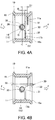
- the first passage 11 is a cylinder shape taking an axis line L1 as the center, and is provided with two sealing parts 11a, 11b which contact with the first butterfly valve 30 in a position on the downstream side of the valve shaft holes 13, 14 in the flowing direction F of exhaust gas.
- the sealing parts 11a, 11b are formed so that in the position which deviates from a central line C of the valve shaft holes 13, 14 for distances D1, D2 (D1>R, D2>R, D1>D2) slightly greater than the radius R of the valve shaft holes 13, 14 on the downstream side, surfaces 32, 33 of the first butterfly valve 30 which is in a closing state that closes the first passage 11 are contacted with each other.
- the sealing parts 11a, 11b are formed as arc-shaped protruding sheets which protrude toward the inside of the first passage 11 except the region near the valve shaft holes 13, 14, so that the first butterfly valve 30 is capable of performing opening and closing action.
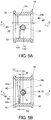
- the second passage 12 is a cylinder shape taking an axis line L2 parallel to the axis line L1 as the center, and is provided with two sealing parts 12a, 12b which contact with the second butterfly valve 40 in a position on the upstream side of the valve shaft holes 14, 15 in the flowing direction F of exhaust gas.
- the sealing parts 12a, 12b are formed so that in the position which deviates from the central line C of the valve shaft holes 14, 15 for distances D1, D2 (D1>R, D2>R, D1>D2) slightly greater than the radius of the valve shaft holes 14, 15 on the upstream side, surfaces 42, 43 of the second butterfly valve 40 which is in a closing state that closes the second passage 12 are contacted with each other.
- sealing parts 12a, 12b are formed as arc-shaped protruding sheets which protrude toward the inside of the second passage 12 except the region near the valve shaft holes 14, 15, so that the second butterfly valve 40 is capable of performing opening and closing action.
- valve shaft holes 13, 14, 15 are formed so as to line up in the central line C extending perpendicularly to the axis lines L1, L2.
- the valve shaft hole 13 is formed to a cylinder shape, which communicates with the first passage 11 from outside on one side of the body 10, and has an internal diameter (2R) with which a first end 21 of the valve shaft 20 is embedded to be rotatable.
- the valve shaft hole 14 is formed to a cylinder shape, which communicates with the first passage 11 and the second passage 12 in the middle part of the body 10, and has an internal diameter (2R) with which an middle part 22 of the valve shaft 20 is embedded to be rotatable.
- the valve shaft holes 15 is formed to a cylinder shape, which communicates with the second passage 12 from outside on the other side of the body 10, and has an internal diameter (2R) with which a second end 23 of the valve shaft 20 is embedded to be rotatable.
- the fitting hole 16 is formed to a cylinder shape which has an internal diameter for the bearing 50 to be securely embedded without any clearance.
- the mounting concave 17 is formed to an internal diameter which securely fits the cylindrical holder 61 that accommodates the ball 63 and the spring 62 or to female screw that screws together with the cylindrical holder 61.
- the valve shaft 20 is formed to a cylinder shape which extends coaxially with the central line C of the valve shafts 13, 14, 15.
- valve shaft 20 is provided with: the first end 21, the middle part 22 and the second end 23, which have the same external diameter; a diameter contracting part 24, which is formed on the external side of the first end 21; a diameter contracting part 25, which is formed on the external side of the second end 23; and a connecting part 26, which is formed at the front end of the diameter contracting part 25.
- the first end 21, the middle part 22, and the second end 23 are formed to the external diameters with which they are embedded separately to the valve shaft holes 13, 14, and 15 of the body 10 so as to be rotatable.
- the first butterfly valve 30 is fixed between the first end 21 and the middle part 22, besides, the second butterfly valve 40 is fixed between the middle part 22 and the second end 23 in a state of deviating the rotation phase for 90° with respect to the first butterfly valve 30.
- the first butterfly valve 30 for opening and closing the first passage 11 is fixed, and the second butterfly valve 40 for opening and closing the second passage 12 is fixed in a phase opposite to the first butterfly valve 30.
- the diameter contracting parts 24, 25 are supported by the bearing 50 mounted on the fitting hole 16 of the body 10 so as to be rotatable.
- the connecting part 26 is formed so as to be connected to an external driving source (not shown) and be affected by a rotary drive force.
- the first butterfly valve 30 is provided with a fixing part 31 which is disk-shaped and is fixed to the valve shaft 20, the surface 32 contacting with the sealing part 11a, and the surface 33 contacting with the sealing part 11b.
- the fixing part 31 is illustrated as a ring shape for passing the valve shaft 20; however, any fixing means can be applied as long as it is a fixing means that revolves the first butterfly valve 30 together with the valve shaft 20.
- fastening means using a screw welding means such as spot welding, and fusion means can be enumerated.
- the first butterfly valve 30 is disposed so as to close the first passage 11 on the downstream side of the valve shaft holes 13, 14 in the state of being fixed to the valve shaft 20.
- the first butterfly valve 30 is disposed so as to close the first passage 11 on the downstream side which deviates from the central line C of the valve shaft holes 13, 14 for the distances D1, D2 greater than the radius R of the valve shaft holes 13, 14.
- the second butterfly valve 40 is provided with a fixing part 41 which is disk-shaped and is fixed to the valve shaft 20, the surface 42 contacting with the sealing part 12a, and the surface 43 contacting with the sealing part 12b.
- the fixing part 41 is illustrated as a ring shape for passing the valve shaft 20; however, any fixing means can be applied as long as it is a fixing means that revolves the first butterfly valve 40 together with the valve shaft 20.
- fastening means using a screw welding means such as spot welding, and fusion means can be enumerated.
- the second butterfly valve 40 is disposed so as to close the second passage 12 on the upstream side of the valve shaft holes 14, 15 in the state of being fixed to the valve shaft 20.
- the second butterfly valve 40 is disposed so as to close the second passage 12 on the upstream side which deviates from the central line C of the valve shaft holes 14, 15 for the distances D1, D2 greater than the radius R of the valve shaft holes 14, 15.
- the two bearing 50 are radial bearings, and are embedded in the fitting hole 16 of the body 10 to support the diameter contracting parts 24, 25 of the valve shaft 20 so that the diameter contracting parts 24, 25 are rotatable.
- valve shaft 20 can be revolved smoothly compared with the situation of being supported through the valve shaft holes 13, 15 only.
- the bearing 50 disposed on the connecting part 26 side of the valve shaft 20 functions as the aforementioned radial bearing, and also functions as the thrust bearing of the valve shaft 20 by receiving the step surface between the second end 23 of the valve shaft 20 and the diameter contracting part 2. For this reason, exhaust gas can be further prevented from leaking outside.
- the pressing component 60 is provided with the cylindrical holder 61 having a bottom, the spring 62, and the ball 63.
- the cylindrical holder 61 is formed to have an external diameter which securely fits in the mounting concave 17 of the body 10 or to male screw that is screws together with the mounting concave 17.
- the spring 62 is a coil-shaped spring, and is formed so as to be embedded in the cylindrical holder 61 with a predetermined compression allowance.
- the ball 63 is disposed so as to receive the pressing force of the compressed spring 62 and contacts an end surface 24a of the diameter contracting part 24 of the valve shaft 20.
- the first butterfly valve 30 is in an opening state which opens the first passage 11 as shown in FIG. 4B
- the second butterfly valve 40 is in a closing state which closes the second passage 12 as shown in FIG. 5B .
- exhaust gas of the engine 1 is smoothly discharged outside from the main exhaust gas pipe 3 via the first passage 11 of the valve device M.
- the second butterfly valve 40 closes the second passage 12 on the upstream side of the valve shaft holes 15, exhaust gas discharged from the main exhaust gas pipe 3 toward the second passage 12 side can be prevented from leaking outside through the valve shaft hole 15.
- the first butterfly valve 30 is in a closing state which closes the first passage 11 as shown in FIG. 4A
- the second butterfly valve 40 is in an opening state which opens the second passage 12 as shown in FIG. 5A .
- exhaust gas of the engine 1 passes the circumvention exhaust gas pipe 4 from the main exhaust gas pipe 3 and goes through the heat exchanger 5, then returns to the main exhaust gas pipe 3 and is discharged outside.
- the structure can be simplified, and the fluid such as exhaust gas can be prevented from leaking outside through the valve shaft hole 15 without increasing the components. Besides, even if the fluid such as exhaust gas leaks from one passage (the second passage 12) to another passage (the first passage 11), the leaked fluid can return to the one passage. For this reason, the heat of the fluid such as exhaust gas can be effectively utilized.
- valve device M provided with two passages (the first passage 11, the second passage 12)and two the butterfly valves (the first butterfly valve 30, the second butterfly valve 40) is shown, but the valve device M is not limited to this, the valve device M being defined by the appended claims.
Landscapes
- Engineering & Computer Science (AREA)
- General Engineering & Computer Science (AREA)
- Mechanical Engineering (AREA)
- Chemical & Material Sciences (AREA)
- Combustion & Propulsion (AREA)
- Lift Valve (AREA)
- Exhaust Silencers (AREA)
- Control Of Throttle Valves Provided In The Intake System Or In The Exhaust System (AREA)
- Valve Housings (AREA)
- Mechanically-Actuated Valves (AREA)
Description
- The present invention relates to a butterfly valve device which opens and closes the fluid passage, in particular to the valve device which is applied to an exhaust heat recovery system and so on that make the exhaust gas of an engine go through a heat exchanger and warm the cooling water, and to an exhaust heat recovery system using this valve device.
- As a conventional valve device, the following valve device is known which is provided with: a body, which has a main passage, a sub-passage and a valve shaft hole perpendicular to the two passages; a valve shaft passed through the valve shaft hole; and two butterfly valves, which are disposed separately on the two passages and are fixed on the valve shaft, and when one of which is closed, the other becomes open (see patent literature 1 for example).
- This valve device is connected to an exhaust gas system of an automobile, and in the state when one of the butterfly valves closes the main passage, the other of the butterfly valves fully opens the sub-passage and leads the exhaust gas to a catalytic converter and so on.
- However, in this valve device, the center of the butterfly valve in the thickness direction is located on the central line of the valve shaft. That is, the valve device is formed in a manner that in the direction in which the exhaust gas passes the passage, the passage, the region overlapping with the valve shaft hole that permits the passing of the valve shaft is opened and closed with the butterfly valve.
- For this reason, there is a risk that when the pressure of the upstream side becomes high due to the resistance of the catalytic converter, the exhaust gas passes through a clearance between the valve shaft and valve shaft hole and flows to the main passage side, making it impossible to effectively utilize the heat of the exhaust gas.
- Patent literature 1: Japanese Laid-open No.
7-4275 -
JP H06 229261 A -
WO 2015/098952 A1 discloses a double eccentric valve provided with a valve seat comprising a seat surface formed at a valve hole edge, a valve body having an annular seal surface formed around the outer periphery of the valve body, and a rotating shaft (cf. Abstract). -
WO 01/50047 A1 -
US 2012/181468 A1 discloses that an engine breathing system valve for an internal combustion engine breathing system includes a valve body, a stem, and a valve member, and that the valve body has a port with a center axis. This document further discloses that the valve body may have a seating surface lying along a cone outer surface of an imaginary cone, that the imaginary cone has a cone center axis, that the stem is carried by the valve body so that it can rotate, that the stem has an axis of rotation radially offset from the port center axis., and that the valve member is connected to the stem and may have a valve member plane axial offset from the axis of rotation (cf. Abstract). -
JP H07 217458 A - The present invention provides an exhaust heat recovery system using a valve device, which solve the problems of the aforementioned prior art, and realizes the prevention of fluid leakage from the valve shaft hole and the effective utilization of exhaust gas heat.
- The present invention is defined by the independent claim. Further embodiments of the present invention are described in the dependent claims.
- According to the valve device with the aforementioned structure, the structure can be simplified, and the fluid such as exhaust gas can be prevented from leaking outside through the valve shaft holes without increasing components. Besides, even if the fluid such as exhaust gas leaks from one passage to another passage, the leaked fluid can return to the one passage. For this reason, the heat of the fluid such as exhaust gas can be effectively utilized.
-
-
FIG. 1 is a schematic diagram showing an exhaust heat recovery system of an engine in which a valve device of the present invention is applied. -
FIG. 2 is a perspective external view showing an embodiment of the valve device of the present invention. -
FIG. 3 is a cross-section view showing a first passage, a second passage and valve shaft holes contained in the valve device shown inFIG. 2 . -
FIG. 4A is a cross-section view which shows the disposing relationship of in the valve device shown inFIG. 2 , and shows the state in which the first butterfly valve closes the first passage. -
FIG. 4B is a cross-section view which shows the disposing relationship of the first passage, the valve shaft holes, the valve shaft, and the first butterfly valve contained in the valve device shown inFIG. 2 , and shows the state in which the first butterfly valve opens the first passage. -
FIG. 5A is a cross-section view which shows the disposing relationship of the second passage, the valve shaft holes, the valve shaft, and the second butterfly valve contained in the valve device shown inFIG. 2 , and shows the state in which the second butterfly valve opens the second passage. -
FIG. 5B is a cross-section view which shows the disposing relationship of the second passage, the valve shaft holes, the valve shaft, and the second butterfly valve contained in the valve device shown inFIG. 2 , and shows the state in which the second butterfly valve closes the second passage. -
FIG. 6 is a cross-section view which shows the state of the first butterfly valve and the second butterfly valve during normal air release when the valve device shown inFIG. 2 is applied to the exhaust heat recovery system. -
FIG. 7 is a cross-section view which shows the state of the first butterfly valve and the second butterfly valve during the leading of exhaust gas to a heat exchanger when the valve device shown inFIG. 2 is applied to the exhaust heat recovery system. - In the following part, the embodiment of the present invention is described with reference to the attached
FIG. 1 to FIG. 7 . - A valve device M of the embodiment is applied to an exhaust heat recovery system S of an engine 1.
- The exhaust heat recovery system S is provided with, in an exhaust system of the engine 1, a main
exhaust gas pipe 3 which is connected to the downstream side of a catalytic unit 2 and passes exhaust gas, a circumventionexhaust gas pipe 4 diverting from the mainexhaust gas pipe 3, the valve device M, aheat exchanger 5, and a pipe 6 for passing the cooling water. - The valve device M is disposed in the midway of the main
exhaust gas pipe 3 and the circumventionexhaust gas pipe 4. - The
heat exchanger 5 is connected to the midway of the circumventionexhaust gas pipe 4 and to the downstream side of the valve device M. - The pipe 6 is formed so as to be led to the
heat exchanger 5 and transfers the heat of exhaust gas to the cooling water of the engine 1. - The valve device M is provided with a
body 10, avalve shaft 20, afirst butterfly valve 30, asecond butterfly valve 40, twobearings 50, and a pressing component 60 (acylindrical holder 61, aspring 62, a ball 63). - The
body 10 is provided with: afirst passage 11 and asecond passage 12 for passing exhaust gas as the fluid;valve shaft holes valve shaft 20 passes; twofitting holes 16 where thebearing 50 is mounted; a mounting concave 17 where thepressing component 60 is mounted; anupstream side flange 18, to which the mainexhaust gas pipe 3 is connected; adownstream side flange 19a, to which the mainexhaust gas pipe 3 is connected; and adownstream side flange 19b, to which the circumventionexhaust gas pipe 4 is connected. - The
first passage 11 is a cylinder shape taking an axis line L1 as the center, and is provided with twosealing parts first butterfly valve 30 in a position on the downstream side of thevalve shaft holes - That is, the sealing
parts valve shaft holes valve shaft holes surfaces first butterfly valve 30 which is in a closing state that closes thefirst passage 11 are contacted with each other. - Here, the
sealing parts first passage 11 except the region near thevalve shaft holes first butterfly valve 30 is capable of performing opening and closing action. - The
second passage 12 is a cylinder shape taking an axis line L2 parallel to the axis line L1 as the center, and is provided with twosealing parts second butterfly valve 40 in a position on the upstream side of thevalve shaft holes - That is, the sealing
parts valve shaft holes valve shaft holes surfaces second butterfly valve 40 which is in a closing state that closes thesecond passage 12 are contacted with each other. - Here, the
sealing parts second passage 12 except the region near thevalve shaft holes second butterfly valve 40 is capable of performing opening and closing action. - The
valve shaft holes - The
valve shaft hole 13 is formed to a cylinder shape, which communicates with thefirst passage 11 from outside on one side of thebody 10, and has an internal diameter (2R) with which afirst end 21 of thevalve shaft 20 is embedded to be rotatable. - The
valve shaft hole 14 is formed to a cylinder shape, which communicates with thefirst passage 11 and thesecond passage 12 in the middle part of thebody 10, and has an internal diameter (2R) with which anmiddle part 22 of thevalve shaft 20 is embedded to be rotatable. - The
valve shaft holes 15 is formed to a cylinder shape, which communicates with thesecond passage 12 from outside on the other side of thebody 10, and has an internal diameter (2R) with which asecond end 23 of thevalve shaft 20 is embedded to be rotatable. - The
fitting hole 16 is formed to a cylinder shape which has an internal diameter for thebearing 50 to be securely embedded without any clearance. - The mounting concave 17 is formed to an internal diameter which securely fits the
cylindrical holder 61 that accommodates theball 63 and thespring 62 or to female screw that screws together with thecylindrical holder 61. - The
valve shaft 20 is formed to a cylinder shape which extends coaxially with the central line C of thevalve shafts - Besides, the
valve shaft 20 is provided with: thefirst end 21, themiddle part 22 and thesecond end 23, which have the same external diameter; adiameter contracting part 24, which is formed on the external side of thefirst end 21; adiameter contracting part 25, which is formed on the external side of thesecond end 23; and a connectingpart 26, which is formed at the front end of thediameter contracting part 25. - The
first end 21, themiddle part 22, and thesecond end 23 are formed to the external diameters with which they are embedded separately to the valve shaft holes 13, 14, and 15 of thebody 10 so as to be rotatable. - In the
valve shaft 20, thefirst butterfly valve 30 is fixed between thefirst end 21 and themiddle part 22, besides, thesecond butterfly valve 40 is fixed between themiddle part 22 and thesecond end 23 in a state of deviating the rotation phase for 90° with respect to thefirst butterfly valve 30. - That is, in the
valve shaft 20, thefirst butterfly valve 30 for opening and closing thefirst passage 11 is fixed, and thesecond butterfly valve 40 for opening and closing thesecond passage 12 is fixed in a phase opposite to thefirst butterfly valve 30. - The
diameter contracting parts fitting hole 16 of thebody 10 so as to be rotatable. - The connecting
part 26 is formed so as to be connected to an external driving source (not shown) and be affected by a rotary drive force. - The
first butterfly valve 30 is provided with a fixingpart 31 which is disk-shaped and is fixed to thevalve shaft 20, thesurface 32 contacting with the sealingpart 11a, and thesurface 33 contacting with the sealingpart 11b. - The fixing
part 31 is illustrated as a ring shape for passing thevalve shaft 20; however, any fixing means can be applied as long as it is a fixing means that revolves thefirst butterfly valve 30 together with thevalve shaft 20. - For example, fastening means using a screw, welding means such as spot welding, and fusion means can be enumerated.
- Besides, the
first butterfly valve 30 is disposed so as to close thefirst passage 11 on the downstream side of the valve shaft holes 13, 14 in the state of being fixed to thevalve shaft 20. - That is, the
first butterfly valve 30 is disposed so as to close thefirst passage 11 on the downstream side which deviates from the central line C of the valve shaft holes 13, 14 for the distances D1, D2 greater than the radius R of the valve shaft holes 13, 14. - As a result, when the
first butterfly valve 30 is disposed deviating on the downstream side of the valve shaft holes 13, 14, by setting the deviating amount to an amount which slightly exceeds the radius R of the valve shaft holes 13, 14, an inertial moment around the center of thevalve shaft 20 can be reduced. For this reason, the opening and closing movement of thefirst butterfly valve 30 can be smooth. - The
second butterfly valve 40 is provided with a fixingpart 41 which is disk-shaped and is fixed to thevalve shaft 20, thesurface 42 contacting with the sealingpart 12a, and thesurface 43 contacting with the sealingpart 12b. - The fixing
part 41 is illustrated as a ring shape for passing thevalve shaft 20; however, any fixing means can be applied as long as it is a fixing means that revolves thefirst butterfly valve 40 together with thevalve shaft 20. - For example, fastening means using a screw, welding means such as spot welding, and fusion means can be enumerated.
- Besides, the
second butterfly valve 40 is disposed so as to close thesecond passage 12 on the upstream side of the valve shaft holes 14, 15 in the state of being fixed to thevalve shaft 20. - That is, the
second butterfly valve 40 is disposed so as to close thesecond passage 12 on the upstream side which deviates from the central line C of the valve shaft holes 14, 15 for the distances D1, D2 greater than the radius R of the valve shaft holes 14, 15. - As a result, when the
second butterfly valve 40 is disposed deviating on the downstream side of the valve shaft holes 14, 15, by setting the deviating amount to an amount which slightly exceeds the radius R of the valve shaft holes 14, 15, the inertial moment around the center of thevalve shaft 20 can be reduced. For this reason, the opening and closing movement of thesecond butterfly valve 40 can be smooth. - The two
bearing 50 are radial bearings, and are embedded in thefitting hole 16 of thebody 10 to support thediameter contracting parts valve shaft 20 so that thediameter contracting parts - As a result, because the
diameter contracting parts valve shaft 20 are supported via thebearing 50 mounted on thebody 10 to be rotatable, thevalve shaft 20 can be revolved smoothly compared with the situation of being supported through the valve shaft holes 13, 15 only. - Besides, by fitting the
bearing 50 to thebody 10, no clearance occurs between the bearing 50 and thebody 10 and between thevalve shaft 20 and thebearing 50, therefore exhaust gas (fluid) can be prevented from leaking out of thebody 10. - In addition, among the two
bearings 50, the bearing 50 disposed on the connectingpart 26 side of the valve shaft 20 (that is, the outside of the valve shaft hole 15) functions as the aforementioned radial bearing, and also functions as the thrust bearing of thevalve shaft 20 by receiving the step surface between thesecond end 23 of thevalve shaft 20 and the diameter contracting part 2. For this reason, exhaust gas can be further prevented from leaking outside. - The
pressing component 60 is provided with thecylindrical holder 61 having a bottom, thespring 62, and theball 63. - The
cylindrical holder 61 is formed to have an external diameter which securely fits in the mounting concave 17 of thebody 10 or to male screw that is screws together with the mounting concave 17. - The
spring 62 is a coil-shaped spring, and is formed so as to be embedded in thecylindrical holder 61 with a predetermined compression allowance. - The
ball 63 is disposed so as to receive the pressing force of thecompressed spring 62 and contacts anend surface 24a of thediameter contracting part 24 of thevalve shaft 20. - As a result, by leaning the
valve shaft 20 with the pressing force of thepressing component 60, the rattle of thevalve shaft 20 can be prevented, and desired opening and closing movement can be obtained. - Next, description is made on the movement of the exhaust heat recovery system S to which the valve device M with the aforementioned structure is applied.
- First, in a normal operation mode shown in
FIG. 6 , thefirst butterfly valve 30 is in an opening state which opens thefirst passage 11 as shown inFIG. 4B , and thesecond butterfly valve 40 is in a closing state which closes thesecond passage 12 as shown inFIG. 5B . - In this case, exhaust gas of the engine 1 is smoothly discharged outside from the main
exhaust gas pipe 3 via thefirst passage 11 of the valve device M. - Here, because the
second butterfly valve 40 closes thesecond passage 12 on the upstream side of the valve shaft holes 15, exhaust gas discharged from the mainexhaust gas pipe 3 toward thesecond passage 12 side can be prevented from leaking outside through thevalve shaft hole 15. - On the other hand, in an exhaust heat recovery mode shown in
FIG. 7 , thefirst butterfly valve 30 is in a closing state which closes thefirst passage 11 as shown inFIG. 4A , and thesecond butterfly valve 40 is in an opening state which opens thesecond passage 12 as shown inFIG. 5A . - In this case, exhaust gas of the engine 1 passes the circumvention
exhaust gas pipe 4 from the mainexhaust gas pipe 3 and goes through theheat exchanger 5, then returns to the mainexhaust gas pipe 3 and is discharged outside. - Here, due to the flowing resistance inside the
heat exchanger 5, the pressure of exhaust gas flowing inside thesecond passage 12 becomes high, and exhaust gas inside thesecond passage 12 may flow into thefirst passage 11 through the clearance between the valve shaft holes 14 and thevalve shaft 20 as shown by the arrow LF inFIG. 7 . - In this case, the downstream side of the valve shaft holes 14 in the
first passage 11 is blocked by thefirst butterfly valve 30, therefore the exhaust gas flowed in does not flows in the mainexhaust gas pipe 3 toward the downstream side, and can return to the circumventionexhaust gas pipe 4 as shown by the arrow LF inFIG. 7 . - For this reason, the exhaust heat of exhaust gas can be effectively utilized.
- As mentioned above, according to the valve device M with the aforementioned structure, the structure can be simplified, and the fluid such as exhaust gas can be prevented from leaking outside through the
valve shaft hole 15 without increasing the components. Besides, even if the fluid such as exhaust gas leaks from one passage (the second passage 12) to another passage (the first passage 11), the leaked fluid can return to the one passage. For this reason, the heat of the fluid such as exhaust gas can be effectively utilized. - In the aforementioned embodiment, the valve device M provided with two passages (the
first passage 11, the second passage 12)and two the butterfly valves (thefirst butterfly valve 30, the second butterfly valve 40) is shown, but the valve device M is not limited to this, the valve device M being defined by the appended claims. -
- S
- Exhaust heat recovery system
- 1
- Engine
- 2
- Catalytic unit
- 3
- Main exhaust gas pipe
- 4
- Circumvention exhaust gas pipe
- 5
- Heat exchanger
- M
- Valve device
- 10
- Body
- 11
- First passage
- 12
- Second passage
- 13, 14, 15
- Valve shaft holes
- R
- Radius of valve shaft hole
- C
- Central line
- 20
- Valve shaft
- 30
- First butterfly valve
- 40
- Second butterfly valve
- 50
- Bearing
- 60
- Pressing component
Claims (6)
- An exhaust heat recovery system (S), comprising: a main exhaust gas pipe (3) for passing an exhaust gas of an engine (1); a circumvention exhaust gas pipe (4), which diverts from the main exhaust gas pipe (3); a valve device (M), which is disposed in a midway of the main exhaust gas pipe (3) and the circumvention exhaust gas pipe (4); and a heat exchanger (5), which is connected to the midway of the circumvention exhaust gas pipe (4) and on a downstream side of the valve device (M); wherein
the valve device (M) comprises:a body (10) that has at least one passage (11, 12) for passing a fluid and valve shaft holes (13, 14, 15);a valve shaft (20), which is passed through the valve shaft holes (13, 14, 15) so as to be rotatable; andat least one butterfly valve (30, 40), which is fixed to the valve shaft (20) and is for opening and closing the passage (11, 12); whereinthe butterfly valve (30, 40) is disposed so as to close the passage (11, 12) on a downstream side or an upstream side of the valve shaft holes (13, 14, 15) in a flow direction of the fluid;the body (10) has a first passage (11) for passing the fluid, a second passage (12) for passing the fluid, and the valve shaft holes (13, 14, 15) formed so as to cause the first passage (11) to communicate with the second passage (12), wherein the main exhaust gas pipe (3) is connected to the first passage (11);a first butterfly valve (30) for opening and closing the first passage (11), and a second butterfly valve (40) for opening and closing the second passage (12) in a phase opposite to the first butterfly valve (30) are fixed to the valve shaft (20);the first butterfly valve (30) is disposed so as to close the first passage (11) on the downstream side of the valve shaft holes (13, 14, 15); andthe first butterfly valve (30) is disposed so as to close the first passage (11) on the downstream side which deviates from the central line (C) of the valve shaft holes (13, 14, 15) for a distance greater than the radius of the valve shaft holes (13, 14, 15). - The exhaust heat recovery system (S) according to claim 1, wherein
the second butterfly valve (40) is disposed so as to close the second passage (12) on the upstream side of the valve shaft holes (13, 14, 15). - The exhaust heat recovery system (S) according to claim 2, wherein
the second butterfly valve (40) is disposed so as to close the second passage (12) on the upstream side which deviates from the central line (C) of the valve shaft holes (13, 14, 15) for a distance greater than the radius of the valve shaft holes (13, 14, 15). - The exhaust heat recovery system (S) according to any one of claims 1 to 3, wherein
the valve shaft (20) is supported at two ends thereof via a bearing (50) mounted on the body (10) so as to be rotatable. - The exhaust heat recovery system (S) according to any one of claims 1 to 4, comprising
a pressing component (60) that presses the valve shaft (20) to one side in an axis direction of the valve shaft (20). - The exhaust heat recovery system (S) according to claim 2, wherein
the first passage (11) is provided with two sealing parts (11a, 11b) which contact with the first butterfly valve (30) in a position on the downstream side of the valve shaft holes (13, 14), the distances of the two sealing parts (11a, 11b) from the central line (C) of the valve shaft holes (13, 14) differing from each other, and
the second passage (12) is provided with two sealing parts (12a, 12b) which contact with the second butterfly valve (40) in a position on the upstream side of the valve shaft holes (14, 15), the distances of the two sealing parts (12a, 12b) from the central line (C) of the valve shaft holes (14, 15) differing from each other.
Applications Claiming Priority (2)
| Application Number | Priority Date | Filing Date | Title |
|---|---|---|---|
| JP2016015974A JP6721351B2 (en) | 2016-01-29 | 2016-01-29 | Valve device and exhaust heat recovery system |
| PCT/JP2017/002729 WO2017131085A1 (en) | 2016-01-29 | 2017-01-26 | Valve device and waste heat recovery system |
Publications (3)
| Publication Number | Publication Date |
|---|---|
| EP3409980A1 EP3409980A1 (en) | 2018-12-05 |
| EP3409980A4 EP3409980A4 (en) | 2019-09-25 |
| EP3409980B1 true EP3409980B1 (en) | 2021-03-03 |
Family
ID=59398517
Family Applications (1)
| Application Number | Title | Priority Date | Filing Date |
|---|---|---|---|
| EP17744315.7A Active EP3409980B1 (en) | 2016-01-29 | 2017-01-26 | Valve device and waste heat recovery system |
Country Status (6)
| Country | Link |
|---|---|
| US (1) | US10787993B2 (en) |
| EP (1) | EP3409980B1 (en) |
| JP (1) | JP6721351B2 (en) |
| KR (1) | KR20180103874A (en) |
| CN (1) | CN108496033B (en) |
| WO (1) | WO2017131085A1 (en) |
Families Citing this family (5)
| Publication number | Priority date | Publication date | Assignee | Title |
|---|---|---|---|---|
| EP3842619B1 (en) * | 2019-12-23 | 2022-09-28 | Hamilton Sundstrand Corporation | Valve assembly for an active clearance control system |
| JP7428533B2 (en) * | 2020-02-14 | 2024-02-06 | 株式会社ミクニ | vehicle exhaust valve device |
| JP7513686B2 (en) | 2021-11-26 | 2024-07-09 | フタバ産業株式会社 | Valve mechanism |
| KR102629245B1 (en) * | 2022-08-09 | 2024-01-25 | 아이스링커 주식회사 | Air sampling pipe auto cleaning system |
| KR102646034B1 (en) * | 2023-07-20 | 2024-03-11 | 에스엠이서브텍주식회사 | Auto cleaning and water trap system for air breathing type fire detector |
Family Cites Families (19)
| Publication number | Priority date | Publication date | Assignee | Title |
|---|---|---|---|---|
| GB1077542A (en) * | 1963-09-30 | 1967-08-02 | Loewy Eng Co Ltd | Improvements in or relating to disc or butter fly valves |
| GB1203029A (en) * | 1966-11-08 | 1970-08-26 | Saunders Valve Co Ltd | Butterfly valves for the control of fluids |
| JPS5233330A (en) | 1975-09-09 | 1977-03-14 | Komatsu Mfg Co Ltd | Selfftravelling system tunnel excavator |
| CN2076193U (en) * | 1990-10-23 | 1991-05-01 | 天津市塘沽阀门厂 | Double-ecentric butterfly valve with metal rigid seal |
| JPH06229261A (en) * | 1993-02-03 | 1994-08-16 | Fuji Oozx Inc | Valve device for high temperature fluid control |
| JPH074275A (en) * | 1993-06-16 | 1995-01-10 | Fuji Oozx Inc | Initial setting method of turning range of valve shaft in fluid control valve device |
| JP3356511B2 (en) * | 1993-12-01 | 2002-12-16 | 株式会社オーケーエム | Butterfly valve |
| JPH07217458A (en) * | 1994-01-31 | 1995-08-15 | Jidosha Kiki Co Ltd | Butterfly valve |
| SE521713C2 (en) * | 1998-11-09 | 2003-12-02 | Stt Emtec Ab | Procedure and apparatus for an EGR system, and such valve |
| US6739579B1 (en) * | 1999-12-29 | 2004-05-25 | Visteon Global Technologies, Inc. | Exhaust valve for combustion engines |
| EP1242760A4 (en) * | 1999-12-29 | 2005-03-23 | Visteon Global Tech Inc | Exhaust valve for combustion engines |
| EP2259000B1 (en) * | 2003-10-17 | 2011-10-05 | Honeywell International Inc. | Internal bypass exhaust gas cooler |
| EP2462326B1 (en) | 2009-08-04 | 2020-05-13 | BorgWarner Inc. | Product comprising an engine breathing system valve and a passage |
| DE102011101948B4 (en) * | 2010-05-19 | 2016-08-11 | Tenneco Gmbh | Method for producing a valve flap device |
| CN103003601B (en) * | 2010-06-29 | 2015-04-01 | 三菱电机株式会社 | Step type valve |
| DE112014006032T5 (en) * | 2013-12-25 | 2016-09-22 | Aisan Kogyo Kabushiki Kaisha | Double eccentric valve |
| EP3121401B1 (en) * | 2014-03-20 | 2019-04-24 | Yanmar Co., Ltd. | Exhaust purification system for ship |
| JP6151657B2 (en) * | 2014-03-20 | 2017-06-21 | ヤンマー株式会社 | Ship exhaust gas purification system |
| CN203880114U (en) * | 2014-03-28 | 2014-10-15 | 安徽省辉煌机械制造有限公司 | Butterfly valve body structure |
-
2016
- 2016-01-29 JP JP2016015974A patent/JP6721351B2/en active Active
-
2017
- 2017-01-26 CN CN201780007960.2A patent/CN108496033B/en not_active Expired - Fee Related
- 2017-01-26 EP EP17744315.7A patent/EP3409980B1/en active Active
- 2017-01-26 WO PCT/JP2017/002729 patent/WO2017131085A1/en not_active Ceased
- 2017-01-26 US US16/073,798 patent/US10787993B2/en active Active
- 2017-01-26 KR KR1020187019134A patent/KR20180103874A/en not_active Withdrawn
Non-Patent Citations (1)
| Title |
|---|
| None * |
Also Published As
| Publication number | Publication date |
|---|---|
| US10787993B2 (en) | 2020-09-29 |
| EP3409980A4 (en) | 2019-09-25 |
| JP6721351B2 (en) | 2020-07-15 |
| CN108496033A (en) | 2018-09-04 |
| KR20180103874A (en) | 2018-09-19 |
| EP3409980A1 (en) | 2018-12-05 |
| CN108496033B (en) | 2021-01-29 |
| WO2017131085A1 (en) | 2017-08-03 |
| JP2017133665A (en) | 2017-08-03 |
| US20190032598A1 (en) | 2019-01-31 |
Similar Documents
| Publication | Publication Date | Title |
|---|---|---|
| JP7070592B2 (en) | Valve device | |
| CN103180644B (en) | High temperature butterfly valve | |
| US10458562B2 (en) | Control valve | |
| US11067181B2 (en) | Valve device | |
| EP3072727B1 (en) | Valve device for vehicle | |
| US10787993B2 (en) | Valve device and exhaust heat recovery system | |
| US6739579B1 (en) | Exhaust valve for combustion engines | |
| JP2021067366A (en) | valve | |
| US11098808B2 (en) | Control valve | |
| CN103946485A (en) | Turbocharger | |
| KR20170128087A (en) | Butterfly valve | |
| CN109073093B (en) | Valve device | |
| JP4842203B2 (en) | Exhaust valve seal structure | |
| US8029672B2 (en) | Filter head | |
| EP1242760A1 (en) | Exhaust valve for combustion engines | |
| CN106286888A (en) | Thermal management module and rotary valve thereof | |
| JP6981952B2 (en) | Exhaust heat recovery device | |
| JP7101544B2 (en) | Control valve | |
| CN114207331A (en) | Fluid valve | |
| JP2001323815A (en) | Exhaust pipe opening / closing valve device | |
| WO2017154204A1 (en) | Valve device | |
| JP2010236683A (en) | Channel open / close valve | |
| JP7619136B2 (en) | Valve device | |
| WO2024237060A1 (en) | Exhaust heat recovery device | |
| JP2012202465A (en) | Valve device |
Legal Events
| Date | Code | Title | Description |
|---|---|---|---|
| STAA | Information on the status of an ep patent application or granted ep patent |
Free format text: STATUS: THE INTERNATIONAL PUBLICATION HAS BEEN MADE |
|
| PUAI | Public reference made under article 153(3) epc to a published international application that has entered the european phase |
Free format text: ORIGINAL CODE: 0009012 |
|
| STAA | Information on the status of an ep patent application or granted ep patent |
Free format text: STATUS: REQUEST FOR EXAMINATION WAS MADE |
|
| 17P | Request for examination filed |
Effective date: 20180726 |
|
| AK | Designated contracting states |
Kind code of ref document: A1 Designated state(s): AL AT BE BG CH CY CZ DE DK EE ES FI FR GB GR HR HU IE IS IT LI LT LU LV MC MK MT NL NO PL PT RO RS SE SI SK SM TR |
|
| AX | Request for extension of the european patent |
Extension state: BA ME |
|
| DAV | Request for validation of the european patent (deleted) | ||
| DAX | Request for extension of the european patent (deleted) | ||
| A4 | Supplementary search report drawn up and despatched |
Effective date: 20190827 |
|
| RIC1 | Information provided on ipc code assigned before grant |
Ipc: F16K 1/226 20060101ALI20190821BHEP Ipc: F16K 1/22 20060101AFI20190821BHEP Ipc: F02D 9/10 20060101ALI20190821BHEP Ipc: F01N 5/02 20060101ALI20190821BHEP Ipc: F02D 9/04 20060101ALI20190821BHEP Ipc: F16K 27/02 20060101ALI20190821BHEP Ipc: F01N 13/08 20100101ALI20190821BHEP |
|
| GRAP | Despatch of communication of intention to grant a patent |
Free format text: ORIGINAL CODE: EPIDOSNIGR1 |
|
| STAA | Information on the status of an ep patent application or granted ep patent |
Free format text: STATUS: GRANT OF PATENT IS INTENDED |
|
| INTG | Intention to grant announced |
Effective date: 20200922 |
|
| GRAS | Grant fee paid |
Free format text: ORIGINAL CODE: EPIDOSNIGR3 |
|
| GRAA | (expected) grant |
Free format text: ORIGINAL CODE: 0009210 |
|
| STAA | Information on the status of an ep patent application or granted ep patent |
Free format text: STATUS: THE PATENT HAS BEEN GRANTED |
|
| AK | Designated contracting states |
Kind code of ref document: B1 Designated state(s): AL AT BE BG CH CY CZ DE DK EE ES FI FR GB GR HR HU IE IS IT LI LT LU LV MC MK MT NL NO PL PT RO RS SE SI SK SM TR |
|
| REG | Reference to a national code |
Ref country code: GB Ref legal event code: FG4D |
|
| REG | Reference to a national code |
Ref country code: AT Ref legal event code: REF Ref document number: 1367580 Country of ref document: AT Kind code of ref document: T Effective date: 20210315 Ref country code: CH Ref legal event code: EP |
|
| REG | Reference to a national code |
Ref country code: DE Ref legal event code: R096 Ref document number: 602017033840 Country of ref document: DE |
|
| REG | Reference to a national code |
Ref country code: IE Ref legal event code: FG4D |
|
| REG | Reference to a national code |
Ref country code: LT Ref legal event code: MG9D |
|
| PG25 | Lapsed in a contracting state [announced via postgrant information from national office to epo] |
Ref country code: NO Free format text: LAPSE BECAUSE OF FAILURE TO SUBMIT A TRANSLATION OF THE DESCRIPTION OR TO PAY THE FEE WITHIN THE PRESCRIBED TIME-LIMIT Effective date: 20210603 Ref country code: FI Free format text: LAPSE BECAUSE OF FAILURE TO SUBMIT A TRANSLATION OF THE DESCRIPTION OR TO PAY THE FEE WITHIN THE PRESCRIBED TIME-LIMIT Effective date: 20210303 Ref country code: GR Free format text: LAPSE BECAUSE OF FAILURE TO SUBMIT A TRANSLATION OF THE DESCRIPTION OR TO PAY THE FEE WITHIN THE PRESCRIBED TIME-LIMIT Effective date: 20210604 Ref country code: HR Free format text: LAPSE BECAUSE OF FAILURE TO SUBMIT A TRANSLATION OF THE DESCRIPTION OR TO PAY THE FEE WITHIN THE PRESCRIBED TIME-LIMIT Effective date: 20210303 Ref country code: LT Free format text: LAPSE BECAUSE OF FAILURE TO SUBMIT A TRANSLATION OF THE DESCRIPTION OR TO PAY THE FEE WITHIN THE PRESCRIBED TIME-LIMIT Effective date: 20210303 Ref country code: BG Free format text: LAPSE BECAUSE OF FAILURE TO SUBMIT A TRANSLATION OF THE DESCRIPTION OR TO PAY THE FEE WITHIN THE PRESCRIBED TIME-LIMIT Effective date: 20210603 |
|
| REG | Reference to a national code |
Ref country code: NL Ref legal event code: MP Effective date: 20210303 |
|
| REG | Reference to a national code |
Ref country code: AT Ref legal event code: MK05 Ref document number: 1367580 Country of ref document: AT Kind code of ref document: T Effective date: 20210303 |
|
| PG25 | Lapsed in a contracting state [announced via postgrant information from national office to epo] |
Ref country code: SE Free format text: LAPSE BECAUSE OF FAILURE TO SUBMIT A TRANSLATION OF THE DESCRIPTION OR TO PAY THE FEE WITHIN THE PRESCRIBED TIME-LIMIT Effective date: 20210303 Ref country code: RS Free format text: LAPSE BECAUSE OF FAILURE TO SUBMIT A TRANSLATION OF THE DESCRIPTION OR TO PAY THE FEE WITHIN THE PRESCRIBED TIME-LIMIT Effective date: 20210303 Ref country code: PL Free format text: LAPSE BECAUSE OF FAILURE TO SUBMIT A TRANSLATION OF THE DESCRIPTION OR TO PAY THE FEE WITHIN THE PRESCRIBED TIME-LIMIT Effective date: 20210303 Ref country code: LV Free format text: LAPSE BECAUSE OF FAILURE TO SUBMIT A TRANSLATION OF THE DESCRIPTION OR TO PAY THE FEE WITHIN THE PRESCRIBED TIME-LIMIT Effective date: 20210303 |
|
| PG25 | Lapsed in a contracting state [announced via postgrant information from national office to epo] |
Ref country code: NL Free format text: LAPSE BECAUSE OF FAILURE TO SUBMIT A TRANSLATION OF THE DESCRIPTION OR TO PAY THE FEE WITHIN THE PRESCRIBED TIME-LIMIT Effective date: 20210303 |
|
| PG25 | Lapsed in a contracting state [announced via postgrant information from national office to epo] |
Ref country code: CZ Free format text: LAPSE BECAUSE OF FAILURE TO SUBMIT A TRANSLATION OF THE DESCRIPTION OR TO PAY THE FEE WITHIN THE PRESCRIBED TIME-LIMIT Effective date: 20210303 Ref country code: EE Free format text: LAPSE BECAUSE OF FAILURE TO SUBMIT A TRANSLATION OF THE DESCRIPTION OR TO PAY THE FEE WITHIN THE PRESCRIBED TIME-LIMIT Effective date: 20210303 Ref country code: AT Free format text: LAPSE BECAUSE OF FAILURE TO SUBMIT A TRANSLATION OF THE DESCRIPTION OR TO PAY THE FEE WITHIN THE PRESCRIBED TIME-LIMIT Effective date: 20210303 Ref country code: SM Free format text: LAPSE BECAUSE OF FAILURE TO SUBMIT A TRANSLATION OF THE DESCRIPTION OR TO PAY THE FEE WITHIN THE PRESCRIBED TIME-LIMIT Effective date: 20210303 |
|
| PG25 | Lapsed in a contracting state [announced via postgrant information from national office to epo] |
Ref country code: SK Free format text: LAPSE BECAUSE OF FAILURE TO SUBMIT A TRANSLATION OF THE DESCRIPTION OR TO PAY THE FEE WITHIN THE PRESCRIBED TIME-LIMIT Effective date: 20210303 Ref country code: RO Free format text: LAPSE BECAUSE OF FAILURE TO SUBMIT A TRANSLATION OF THE DESCRIPTION OR TO PAY THE FEE WITHIN THE PRESCRIBED TIME-LIMIT Effective date: 20210303 Ref country code: PT Free format text: LAPSE BECAUSE OF FAILURE TO SUBMIT A TRANSLATION OF THE DESCRIPTION OR TO PAY THE FEE WITHIN THE PRESCRIBED TIME-LIMIT Effective date: 20210705 Ref country code: IS Free format text: LAPSE BECAUSE OF FAILURE TO SUBMIT A TRANSLATION OF THE DESCRIPTION OR TO PAY THE FEE WITHIN THE PRESCRIBED TIME-LIMIT Effective date: 20210703 |
|
| REG | Reference to a national code |
Ref country code: DE Ref legal event code: R097 Ref document number: 602017033840 Country of ref document: DE |
|
| PLBE | No opposition filed within time limit |
Free format text: ORIGINAL CODE: 0009261 |
|
| STAA | Information on the status of an ep patent application or granted ep patent |
Free format text: STATUS: NO OPPOSITION FILED WITHIN TIME LIMIT |
|
| PG25 | Lapsed in a contracting state [announced via postgrant information from national office to epo] |
Ref country code: ES Free format text: LAPSE BECAUSE OF FAILURE TO SUBMIT A TRANSLATION OF THE DESCRIPTION OR TO PAY THE FEE WITHIN THE PRESCRIBED TIME-LIMIT Effective date: 20210303 Ref country code: DK Free format text: LAPSE BECAUSE OF FAILURE TO SUBMIT A TRANSLATION OF THE DESCRIPTION OR TO PAY THE FEE WITHIN THE PRESCRIBED TIME-LIMIT Effective date: 20210303 Ref country code: AL Free format text: LAPSE BECAUSE OF FAILURE TO SUBMIT A TRANSLATION OF THE DESCRIPTION OR TO PAY THE FEE WITHIN THE PRESCRIBED TIME-LIMIT Effective date: 20210303 |
|
| 26N | No opposition filed |
Effective date: 20211206 |
|
| PG25 | Lapsed in a contracting state [announced via postgrant information from national office to epo] |
Ref country code: SI Free format text: LAPSE BECAUSE OF FAILURE TO SUBMIT A TRANSLATION OF THE DESCRIPTION OR TO PAY THE FEE WITHIN THE PRESCRIBED TIME-LIMIT Effective date: 20210303 |
|
| PG25 | Lapsed in a contracting state [announced via postgrant information from national office to epo] |
Ref country code: IT Free format text: LAPSE BECAUSE OF FAILURE TO SUBMIT A TRANSLATION OF THE DESCRIPTION OR TO PAY THE FEE WITHIN THE PRESCRIBED TIME-LIMIT Effective date: 20210303 |
|
| PG25 | Lapsed in a contracting state [announced via postgrant information from national office to epo] |
Ref country code: IS Free format text: LAPSE BECAUSE OF FAILURE TO SUBMIT A TRANSLATION OF THE DESCRIPTION OR TO PAY THE FEE WITHIN THE PRESCRIBED TIME-LIMIT Effective date: 20210703 |
|
| PG25 | Lapsed in a contracting state [announced via postgrant information from national office to epo] |
Ref country code: MC Free format text: LAPSE BECAUSE OF FAILURE TO SUBMIT A TRANSLATION OF THE DESCRIPTION OR TO PAY THE FEE WITHIN THE PRESCRIBED TIME-LIMIT Effective date: 20210303 |
|
| REG | Reference to a national code |
Ref country code: CH Ref legal event code: PL |
|
| GBPC | Gb: european patent ceased through non-payment of renewal fee |
Effective date: 20220126 |
|
| REG | Reference to a national code |
Ref country code: BE Ref legal event code: MM Effective date: 20220131 |
|
| PG25 | Lapsed in a contracting state [announced via postgrant information from national office to epo] |
Ref country code: LU Free format text: LAPSE BECAUSE OF NON-PAYMENT OF DUE FEES Effective date: 20220126 Ref country code: GB Free format text: LAPSE BECAUSE OF NON-PAYMENT OF DUE FEES Effective date: 20220126 |
|
| PG25 | Lapsed in a contracting state [announced via postgrant information from national office to epo] |
Ref country code: BE Free format text: LAPSE BECAUSE OF NON-PAYMENT OF DUE FEES Effective date: 20220131 |
|
| PG25 | Lapsed in a contracting state [announced via postgrant information from national office to epo] |
Ref country code: LI Free format text: LAPSE BECAUSE OF NON-PAYMENT OF DUE FEES Effective date: 20220131 Ref country code: CH Free format text: LAPSE BECAUSE OF NON-PAYMENT OF DUE FEES Effective date: 20220131 |
|
| PG25 | Lapsed in a contracting state [announced via postgrant information from national office to epo] |
Ref country code: IE Free format text: LAPSE BECAUSE OF NON-PAYMENT OF DUE FEES Effective date: 20220126 |
|
| PG25 | Lapsed in a contracting state [announced via postgrant information from national office to epo] |
Ref country code: HU Free format text: LAPSE BECAUSE OF FAILURE TO SUBMIT A TRANSLATION OF THE DESCRIPTION OR TO PAY THE FEE WITHIN THE PRESCRIBED TIME-LIMIT; INVALID AB INITIO Effective date: 20170126 |
|
| PG25 | Lapsed in a contracting state [announced via postgrant information from national office to epo] |
Ref country code: MK Free format text: LAPSE BECAUSE OF FAILURE TO SUBMIT A TRANSLATION OF THE DESCRIPTION OR TO PAY THE FEE WITHIN THE PRESCRIBED TIME-LIMIT Effective date: 20210303 Ref country code: CY Free format text: LAPSE BECAUSE OF FAILURE TO SUBMIT A TRANSLATION OF THE DESCRIPTION OR TO PAY THE FEE WITHIN THE PRESCRIBED TIME-LIMIT Effective date: 20210303 |
|
| PG25 | Lapsed in a contracting state [announced via postgrant information from national office to epo] |
Ref country code: TR Free format text: LAPSE BECAUSE OF FAILURE TO SUBMIT A TRANSLATION OF THE DESCRIPTION OR TO PAY THE FEE WITHIN THE PRESCRIBED TIME-LIMIT Effective date: 20210303 |
|
| PG25 | Lapsed in a contracting state [announced via postgrant information from national office to epo] |
Ref country code: MT Free format text: LAPSE BECAUSE OF FAILURE TO SUBMIT A TRANSLATION OF THE DESCRIPTION OR TO PAY THE FEE WITHIN THE PRESCRIBED TIME-LIMIT Effective date: 20210303 |
|
| PGFP | Annual fee paid to national office [announced via postgrant information from national office to epo] |
Ref country code: FR Payment date: 20251128 Year of fee payment: 10 |
|
| PGFP | Annual fee paid to national office [announced via postgrant information from national office to epo] |
Ref country code: DE Payment date: 20251203 Year of fee payment: 10 |