EP3409886A2 - Airfoil having serpentine core resupply flow control - Google Patents
Airfoil having serpentine core resupply flow control Download PDFInfo
- Publication number
- EP3409886A2 EP3409886A2 EP18165635.6A EP18165635A EP3409886A2 EP 3409886 A2 EP3409886 A2 EP 3409886A2 EP 18165635 A EP18165635 A EP 18165635A EP 3409886 A2 EP3409886 A2 EP 3409886A2
- Authority
- EP
- European Patent Office
- Prior art keywords
- core
- cavity
- serpentine
- resupply
- airfoil
- Prior art date
- Legal status (The legal status is an assumption and is not a legal conclusion. Google has not performed a legal analysis and makes no representation as to the accuracy of the status listed.)
- Withdrawn
Links
Images



Classifications
-
- F—MECHANICAL ENGINEERING; LIGHTING; HEATING; WEAPONS; BLASTING
- F01—MACHINES OR ENGINES IN GENERAL; ENGINE PLANTS IN GENERAL; STEAM ENGINES
- F01D—NON-POSITIVE DISPLACEMENT MACHINES OR ENGINES, e.g. STEAM TURBINES
- F01D5/00—Blades; Blade-carrying members; Heating, heat-insulating, cooling or antivibration means on the blades or the members
- F01D5/12—Blades
- F01D5/14—Form or construction
- F01D5/18—Hollow blades, i.e. blades with cooling or heating channels or cavities; Heating, heat-insulating or cooling means on blades
- F01D5/187—Convection cooling
-
- B—PERFORMING OPERATIONS; TRANSPORTING
- B22—CASTING; POWDER METALLURGY
- B22C—FOUNDRY MOULDING
- B22C9/00—Moulds or cores; Moulding processes
- B22C9/10—Cores; Manufacture or installation of cores
- B22C9/103—Multipart cores
-
- B—PERFORMING OPERATIONS; TRANSPORTING
- B22—CASTING; POWDER METALLURGY
- B22C—FOUNDRY MOULDING
- B22C9/00—Moulds or cores; Moulding processes
- B22C9/22—Moulds for peculiarly-shaped castings
- B22C9/24—Moulds for peculiarly-shaped castings for hollow articles
-
- F—MECHANICAL ENGINEERING; LIGHTING; HEATING; WEAPONS; BLASTING
- F01—MACHINES OR ENGINES IN GENERAL; ENGINE PLANTS IN GENERAL; STEAM ENGINES
- F01D—NON-POSITIVE DISPLACEMENT MACHINES OR ENGINES, e.g. STEAM TURBINES
- F01D25/00—Component parts, details, or accessories, not provided for in, or of interest apart from, other groups
- F01D25/08—Cooling; Heating; Heat-insulation
- F01D25/12—Cooling
-
- F—MECHANICAL ENGINEERING; LIGHTING; HEATING; WEAPONS; BLASTING
- F01—MACHINES OR ENGINES IN GENERAL; ENGINE PLANTS IN GENERAL; STEAM ENGINES
- F01D—NON-POSITIVE DISPLACEMENT MACHINES OR ENGINES, e.g. STEAM TURBINES
- F01D5/00—Blades; Blade-carrying members; Heating, heat-insulating, cooling or antivibration means on the blades or the members
- F01D5/02—Blade-carrying members, e.g. rotors
- F01D5/08—Heating, heat-insulating or cooling means
- F01D5/081—Cooling fluid being directed on the side of the rotor disc or at the roots of the blades
-
- F—MECHANICAL ENGINEERING; LIGHTING; HEATING; WEAPONS; BLASTING
- F01—MACHINES OR ENGINES IN GENERAL; ENGINE PLANTS IN GENERAL; STEAM ENGINES
- F01D—NON-POSITIVE DISPLACEMENT MACHINES OR ENGINES, e.g. STEAM TURBINES
- F01D9/00—Stators
- F01D9/02—Nozzles; Nozzle boxes; Stator blades; Guide conduits, e.g. individual nozzles
- F01D9/04—Nozzles; Nozzle boxes; Stator blades; Guide conduits, e.g. individual nozzles forming ring or sector
- F01D9/041—Nozzles; Nozzle boxes; Stator blades; Guide conduits, e.g. individual nozzles forming ring or sector using blades
-
- F—MECHANICAL ENGINEERING; LIGHTING; HEATING; WEAPONS; BLASTING
- F05—INDEXING SCHEMES RELATING TO ENGINES OR PUMPS IN VARIOUS SUBCLASSES OF CLASSES F01-F04
- F05D—INDEXING SCHEME FOR ASPECTS RELATING TO NON-POSITIVE-DISPLACEMENT MACHINES OR ENGINES, GAS-TURBINES OR JET-PROPULSION PLANTS
- F05D2220/00—Application
- F05D2220/30—Application in turbines
- F05D2220/32—Application in turbines in gas turbines
-
- F—MECHANICAL ENGINEERING; LIGHTING; HEATING; WEAPONS; BLASTING
- F05—INDEXING SCHEMES RELATING TO ENGINES OR PUMPS IN VARIOUS SUBCLASSES OF CLASSES F01-F04
- F05D—INDEXING SCHEME FOR ASPECTS RELATING TO NON-POSITIVE-DISPLACEMENT MACHINES OR ENGINES, GAS-TURBINES OR JET-PROPULSION PLANTS
- F05D2230/00—Manufacture
- F05D2230/20—Manufacture essentially without removing material
- F05D2230/21—Manufacture essentially without removing material by casting
- F05D2230/211—Manufacture essentially without removing material by casting by precision casting, e.g. microfusing or investment casting
-
- F—MECHANICAL ENGINEERING; LIGHTING; HEATING; WEAPONS; BLASTING
- F05—INDEXING SCHEMES RELATING TO ENGINES OR PUMPS IN VARIOUS SUBCLASSES OF CLASSES F01-F04
- F05D—INDEXING SCHEME FOR ASPECTS RELATING TO NON-POSITIVE-DISPLACEMENT MACHINES OR ENGINES, GAS-TURBINES OR JET-PROPULSION PLANTS
- F05D2250/00—Geometry
- F05D2250/10—Two-dimensional
- F05D2250/18—Two-dimensional patterned
- F05D2250/185—Two-dimensional patterned serpentine-like
-
- F—MECHANICAL ENGINEERING; LIGHTING; HEATING; WEAPONS; BLASTING
- F05—INDEXING SCHEMES RELATING TO ENGINES OR PUMPS IN VARIOUS SUBCLASSES OF CLASSES F01-F04
- F05D—INDEXING SCHEME FOR ASPECTS RELATING TO NON-POSITIVE-DISPLACEMENT MACHINES OR ENGINES, GAS-TURBINES OR JET-PROPULSION PLANTS
- F05D2260/00—Function
- F05D2260/20—Heat transfer, e.g. cooling
- F05D2260/202—Heat transfer, e.g. cooling by film cooling
-
- Y—GENERAL TAGGING OF NEW TECHNOLOGICAL DEVELOPMENTS; GENERAL TAGGING OF CROSS-SECTIONAL TECHNOLOGIES SPANNING OVER SEVERAL SECTIONS OF THE IPC; TECHNICAL SUBJECTS COVERED BY FORMER USPC CROSS-REFERENCE ART COLLECTIONS [XRACs] AND DIGESTS
- Y02—TECHNOLOGIES OR APPLICATIONS FOR MITIGATION OR ADAPTATION AGAINST CLIMATE CHANGE
- Y02T—CLIMATE CHANGE MITIGATION TECHNOLOGIES RELATED TO TRANSPORTATION
- Y02T50/00—Aeronautics or air transport
- Y02T50/60—Efficient propulsion technologies, e.g. for aircraft
Definitions
- further embodiments of the cores may include that the flow control feature core forms a structure that connects the resupply cavity core and the second serpentine cavity core.
- the low speed spool 30 generally includes an inner shaft 40 that interconnects a fan 42, a low pressure compressor 44 and a low pressure turbine 46.
- the inner shaft 40 is connected to the fan 42 through a speed change mechanism, which in exemplary gas turbine engine 20 is illustrated as a geared architecture 48 to drive the fan 42 at a lower speed than the low speed spool 30.
- the high speed spool 32 includes an outer shaft 50 that interconnects a high pressure compressor 52 and high pressure turbine 54.
- a combustor 56 is arranged in exemplary gas turbine 20 between the high pressure compressor 52 and the high pressure turbine 54.
- An engine static structure 36 is arranged generally between the high pressure turbine 54 and the low pressure turbine 46.
- the engine static structure 36 further supports bearing systems 38 in the turbine section 28.
- the inner shaft 40 and the outer shaft 50 are concentric and rotate via bearing systems 38 about the engine central longitudinal axis A which is collinear with their longitudinal axes.
- the airfoil 60 includes an airfoil body 90 having a pressure side 92, a suction side 94, a root region 96, a tip region 98, a leading edge 100, and a trailing edge 102.
- the pressure side 92 is disposed opposite the suction side 94.
- the pressure side 92 and the suction side 94 each extend radially from the root region 96 to the tip region 98.
- the term "radial" refers to radial with respect to an engine axis (e.g., engine central longitudinal axis A shown in FIG. 1 ).
- the junction 626 is arranged with a flow control feature 628.
- the flow control feature 628 can have a cross sectional flow area that is defined to incorporate variable rates of flow cavity area convergence/divergence (e.g., taper/expansion) and blending to better tailor the transition and size of the flow control feature 628.
- FIG. 9 a schematic illustration of airflow control as achieved in an airfoil having a flow control feature 928 in accordance with an embodiment of the present disclosure is shown.
- the flow control features of the present disclosure can prevent improper flow direction of resupply air.
- flow control features in accordance with embodiments of the present disclosure can provide other properties, including flow control related to merging of flows within a third serpentine cavity 914.
- serpentine cooling air 918 flows radially inward (downward on the page) within a second serpentine cavity 912, as described above.
- the ejection hole cores 1172 can be eliminated entirely.
- the air ejection holes 1066 can be formed in a post machining process that is applied to a formed airfoil/platform/attachment, etc.
- Such post machining process can include, but is not limited to, laser drilling, conventional electrical discharge machining ("EDM”), high speed EDM, electrochemical machining, laser ablation, micro water jet, water jet with laser assist, etc.
- EDM electrical discharge machining
- electrochemical machining laser ablation
- micro water jet water jet with laser assist
- the ejection hole cores 1172 shown schematically in FIG. 11 demonstrate the location where the air cooling holes would be formed relative to the core 1132.
- the air ejection holes 1066 can be designed (e.g., aperture, size, length, diameter, number, location, etc.) to eject between 1% and 75% of the serpentine cooling air flow, thus enabling a similar proportion of resupply cooling air flow to be provided by the resupply cavity at the third serpentine cavity and/or trailing edge slot.
- the air ejection holes are arranged to eject between 1% and 75% of the serpentine cooling air. Such arrangement can provide a significant impact on the coolant temperature supplying the third serpentine (trailing edge) cavity and trailing edge discharge apertures.
- the number, arrangement, angling, size, shape, internal geometry, etc. of the air ejection holes can be appropriately configured to achieve such results.
- the arrangement and placement of the air ejection holes 1066 can be positioned forward (toward a leading edge of the airfoil 1000) relative to the resupply cavity (formed by the resupply cavity core 1136). As such, the ejection of the serpentine cooling air will occur upstream of the resupply air being supplied into the third serpentine cavity.
Landscapes
- Engineering & Computer Science (AREA)
- Mechanical Engineering (AREA)
- General Engineering & Computer Science (AREA)
- Turbine Rotor Nozzle Sealing (AREA)
Abstract
Description
- Illustrative embodiments pertain to the art of turbomachinery, and specifically to turbine rotor components.
- Gas turbine engines are rotary-type combustion turbine engines built around a power core made up of a compressor, combustor and turbine, arranged in flow series with an upstream inlet and downstream exhaust. The compressor compresses air from the inlet, which is mixed with fuel in the combustor and ignited to generate hot combustion gas. The turbine extracts energy from the expanding combustion gas, and drives the compressor via a common shaft. Energy is delivered in the form of rotational energy in the shaft, reactive thrust from the exhaust, or both.
- The individual compressor and turbine sections in each spool are subdivided into a number of stages, which are formed of alternating rows of rotor blade and stator vane airfoils. The airfoils are shaped to turn, accelerate and compress the working fluid flow, or to generate lift for conversion to rotational energy in the turbine.
- Airfoils may incorporate trailing edge core geometries that include and/or require a resupply feed to provide additional cooling air to the trailing edge region. This is done by thickening a rib forward of a connection between a serpentine passage and a resupply source in order to angle the resupply air away from the exit of the serpentine. Such ribs can increase part weight and may create additional challenges associated with manufacturing producibility. Accordingly, improved means for providing cooling at a trailing edge region of an airfoil may be desirable.
- According to some embodiments, airfoils for gas turbine engines are provided. The airfoil includes an airfoil body having a leading edge and a trailing edge, a first serpentine cavity formed within the airfoil body and defining a first portion of a serpentine cooling flow path and enabling a cooling flow in a first direction within the airfoil body, a second serpentine cavity fluidly connected to the first serpentine cavity and defining a second portion of the serpentine cooling flow path and enabling a cooling flow in a second direction, a third serpentine cavity fluidly connected to the second serpentine cavity and defining a third portion of the serpentine cooling flow path and enabling a cooling flow in at least one of the first direction or a third direction, wherein a serpentine cooling air flows through the serpentine cooling flow path, a resupply cavity fluidly connected to the third serpentine cavity and arranged to supply a resupply air to the third serpentine cavity, a junction defined at the location where both the second serpentine cavity and the resupply cavity fluidly connect to the third serpentine cavity, and a flow control feature located at the junction and arranged to at least one of (i) turn the serpentine cooling air from the second direction to at least one of the first or third direction or (ii) prevent the resupply air from flowing into the second serpentine cavity.
- In addition to one or more of the features described herein, or as an alternative, further embodiments of the airfoils may include that the flow control feature defines a flow control cavity that fluidly connects the resupply cavity and the second serpentine cavity.
- In addition to one or more of the features described herein, or as an alternative, further embodiments of the airfoils may include that the flow control cavity includes a first tapering cavity portion and a second tapering cavity portion and a cavity inflection point between the first and second tapering cavity portions, wherein each of the first and second tapering cavity portions expand in width in a direction away from the cavity inflection point.
- In addition to one or more of the features described herein, or as an alternative, further embodiments of the airfoils may include that the first tapering cavity portion has a first width at a maximum thereof, a second width is defined at the cavity inflection point, and the second tapering cavity has a third width at a maximum thereof, wherein the first width and the second width are equal.
- In addition to one or more of the features described herein, or as an alternative, further embodiments of the airfoils may include that the flow control feature includes a serpentine flow control subportion arranged to turn the serpentine cooling air into a direction substantially similar to a flow direction of the resupply air.
- In addition to one or more of the features described herein, or as an alternative, further embodiments of the airfoils may include that the flow control feature includes a resupply flow control subportion arranged to prevent the resupply air from entering the second serpentine cavity.
- In addition to one or more of the features described herein, or as an alternative, further embodiments of the airfoils may include at least one air ejection hole arranged to eject at least some of the serpentine cooling air to an external surface of the airfoil body.
- In addition to one or more of the features described herein, or as an alternative, further embodiments of the airfoils may include that the at least one air ejection hole forms at least one of a gas path aperture or a platform aperture on the external surface of the airfoil body.
- In addition to one or more of the features described herein, or as an alternative, further embodiments of the airfoils may include that the at least one air ejection hole is arranged at a position upstream of the resupply cavity along a flow path of the serpentine cooling air.
- In addition to one or more of the features described herein, or as an alternative, further embodiments of the airfoils may include that the at least one air ejection hole is configured to eject at least thirty percent of the serpentine cooling air.
- According to some embodiments, cores for manufacturing airfoils of gas turbine engines are provided. The cores include a first serpentine cavity core arranged to define a first serpentine cavity with a cooling flow in a first direction within a formed airfoil body, a second serpentine cavity core connected to the first serpentine cavity core and arranged to define a second serpentine cavity with a cooling flow in a second direction within the formed airfoil body, a third serpentine cavity core fluidly connected to the second serpentine cavity core and arranged to define a third serpentine cavity with a cooling flow in at least one of the first direction or a third direction within the formed airfoil body, a resupply cavity core connected to the third serpentine cavity core and arranged to form a resupply cavity in the formed airfoil body, wherein a core junction is defined at the location where the second serpentine cavity core and the resupply cavity core connect to the third serpentine cavity core, and a flow control feature core including a first tapering core portion and a second tapering core portion and a core inflection point between the first and second tapering core portions, wherein each of the first and second tapering core portions expand in thickness in a direction away from the core inflection point.
- In addition to one or more of the features described herein, or as an alternative, further embodiments of the cores may include that the flow control feature core forms a structure that connects the resupply cavity core and the second serpentine cavity core.
- In addition to one or more of the features described herein, or as an alternative, further embodiments of the cores may include that the first tapering core portion has a first core thickness at a maximum thereof, a second core thickness is defined at the core inflection point, and the second tapering core has a third core thickness at a maximum thereof, wherein the first core thickness and the third core thickness are equal.
- In addition to one or more of the features described herein, or as an alternative, further embodiments of the cores may include that the flow control feature core includes a serpentine flow control core subportion arranged to form a structure in an airfoil body that turns a serpentine cooling air into a direction substantially similar to a flow direction of a resupply air.
- In addition to one or more of the features described herein, or as an alternative, further embodiments of the cores may include that the flow control feature core includes a resupply flow control core subportion arranged to form a structure in an airfoil body that prevents a resupply air from entering a second serpentine cavity.
- In addition to one or more of the features described herein, or as an alternative, further embodiments of the cores may include at least one ejection hole core arranged to form apertures within an airfoil body, the apertures enabling ejection of a portion of air from a second serpentine cavity.
- In addition to one or more of the features described herein, or as an alternative, further embodiments of the cores may include that the at least one air ejection hole core is integrally formed with the core.
- In addition to one or more of the features described herein, or as an alternative, further embodiments of the cores may include that the at least one air ejection hole core is arranged at a position forward of the resupply cavity core.
- In addition to one or more of the features described herein, or as an alternative, further embodiments of the cores may include that the at least one air ejection hole core is configured to form an ejection hole that will eject at least thirty percent of a serpentine cooling air from a second serpentine cavity.
- The foregoing features and elements may be combined in various combinations without exclusivity, unless expressly indicated otherwise. These features and elements as well as the operation thereof will become more apparent in light of the following description and the accompanying drawings. It should be understood, however, the following description and drawings are intended to be illustrative and explanatory in nature and non-limiting.
- The following descriptions should not be considered limiting in any way. With reference to the accompanying drawings, like elements are numbered alike: The subject matter is particularly pointed out and distinctly claimed at the conclusion of the specification. The foregoing and other features, and advantages of the present disclosure are apparent from the following detailed description taken in conjunction with the accompanying drawings in which like elements may be numbered alike and:
-
FIG. 1 is a schematic cross-sectional illustration of a gas turbine engine; -
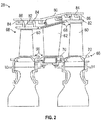
FIG. 2 is a schematic illustration of a portion of a turbine section of the gas turbine engine ofFIG. 1 ; -
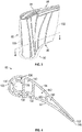
FIG. 3 is a perspective view of an airfoil that can incorporate embodiments of the present disclosure; -
FIG. 4 is a partial cross-sectional view of the airfoil ofFIG. 3 as viewed along the line 4-4 shown inFIG. 3 ; -
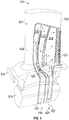
FIG. 5 is a schematic illustration of an airfoil in accordance with an embodiment of the present disclosure; -
FIG. 6 is a schematic illustration of airflow through cavities of an airfoil in accordance with an embodiment of the present disclosure; -
FIG. 7A is an illustrative side view of a core junction in accordance with an embodiment of the present disclosure; -
FIG. 7B is a cross-sectional illustration of the core junction ofFIG. 7A as viewed along the line B-B shown inFIG. 7A ; -
FIG. 8 is a schematic illustration of a flow control feature of an airfoil in accordance with an embodiment of the present disclosure; -
FIG. 9 is a schematic illustration of airflow control as achieved in an airfoil having a flow control feature in accordance with an embodiment of the present disclosure; -
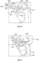
FIG. 10 is a partial schematic illustration of an airfoil in accordance with an embodiment of the present disclosure; and -
FIG. 11 is a partial schematic illustration of a core used to form the airfoil shown inFIG. 10 , in accordance with an embodiment of the present disclosure. - Detailed descriptions of one or more embodiments of the disclosed apparatus and/or methods are presented herein by way of exemplification and not limitation with reference to the Figures.
-
FIG. 1 schematically illustrates agas turbine engine 20. Thegas turbine engine 20 is disclosed herein as a two-spool turbofan that generally incorporates afan section 22, acompressor section 24, acombustor section 26 and aturbine section 28. Alternative engines might include an augmentor section (not shown) among other systems or features. Thefan section 22 drives air along a bypass flow path B in a bypass duct, while thecompressor section 24 drives air along a core flow path C for compression and communication into thecombustor section 26 then expansion through theturbine section 28. Although depicted as a two-spool turbofan gas turbine engine in the disclosed non-limiting embodiment, it should be understood that the concepts described herein are not limited to use with two-spool turbofans as the teachings may be applied to other types of turbine engines including three-spool architectures. - The
exemplary engine 20 generally includes alow speed spool 30 and ahigh speed spool 32 mounted for rotation about an engine central longitudinal axis A relative to an enginestatic structure 36 viaseveral bearing systems 38. It should be understood that various bearingsystems 38 at various locations may alternatively or additionally be provided, and the location of bearingsystems 38 may be varied as appropriate to the application. - The
low speed spool 30 generally includes aninner shaft 40 that interconnects afan 42, alow pressure compressor 44 and alow pressure turbine 46. Theinner shaft 40 is connected to thefan 42 through a speed change mechanism, which in exemplarygas turbine engine 20 is illustrated as a gearedarchitecture 48 to drive thefan 42 at a lower speed than thelow speed spool 30. Thehigh speed spool 32 includes anouter shaft 50 that interconnects ahigh pressure compressor 52 andhigh pressure turbine 54. Acombustor 56 is arranged inexemplary gas turbine 20 between thehigh pressure compressor 52 and thehigh pressure turbine 54. An enginestatic structure 36 is arranged generally between thehigh pressure turbine 54 and thelow pressure turbine 46. The enginestatic structure 36 furthersupports bearing systems 38 in theturbine section 28. Theinner shaft 40 and theouter shaft 50 are concentric and rotate via bearingsystems 38 about the engine central longitudinal axis A which is collinear with their longitudinal axes. - The core airflow is compressed by the
low pressure compressor 44 then thehigh pressure compressor 52, mixed and burned with fuel in thecombustor 56, then expanded over thehigh pressure turbine 54 andlow pressure turbine 46. Theturbines low speed spool 30 andhigh speed spool 32 in response to the expansion. It will be appreciated that each of the positions of thefan section 22,compressor section 24,combustor section 26,turbine section 28, and fandrive gear system 48 may be varied. For example,gear system 48 may be located aft ofcombustor section 26 or even aft ofturbine section 28, andfan section 22 may be positioned forward or aft of the location ofgear system 48. - The
engine 20 in one example is a high-bypass geared aircraft engine. In a further example, theengine 20 bypass ratio is greater than about six (6), with an example embodiment being greater than about ten (10), the gearedarchitecture 48 is an epicyclic gear train, such as a planetary gear system or other gear system, with a gear reduction ratio of greater than about 2.3 and thelow pressure turbine 46 has a pressure ratio that is greater than about five. In one disclosed embodiment, theengine 20 bypass ratio is greater than about ten (10:1), the fan diameter is significantly larger than that of thelow pressure compressor 44, and thelow pressure turbine 46 has a pressure ratio that is greater than about five 5:1.Low pressure turbine 46 pressure ratio is pressure measured prior to inlet oflow pressure turbine 46 as related to the pressure at the outlet of thelow pressure turbine 46 prior to an exhaust nozzle. The gearedarchitecture 48 may be an epicycle gear train, such as a planetary gear system or other gear system, with a gear reduction ratio of greater than about 2.3:1. It should be understood, however, that the above parameters are only exemplary of one embodiment of a geared architecture engine and that the present disclosure is applicable to other gas turbine engines including direct drive turbofans. - A significant amount of thrust is provided by the bypass flow B due to the high bypass ratio. The
fan section 22 of theengine 20 is designed for a particular flight condition--typically cruise at about 0.8Mach and about 35,000 feet (10,688 meters). The flight condition of 0.8 Mach and 35,000 ft (10,688 meters), with the engine at its best fuel consumption--also known as "bucket cruise Thrust Specific Fuel Consumption ('TSFC')"--is the industry standard parameter of lbm of fuel being burned divided by lbf of thrust the engine produces at that minimum point. "Low fan pressure ratio" is the pressure ratio across the fan blade alone, without a Fan Exit Guide Vane ("FEGV") system. The low fan pressure ratio as disclosed herein according to one non-limiting embodiment is less than about 1.45. "Low corrected fan tip speed" is the actual fan tip speed in ft/sec divided by an industry standard temperature correction of [(Tram °R)/(518.7 °R)]0.5. The "Low corrected fan tip speed" as disclosed herein according to one non-limiting embodiment is less than about 1150 ft/second (350.5 m/sec). - Although the
gas turbine engine 20 is depicted as a turbofan, it should be understood that the concepts described herein are not limited to use with the described configuration, as the teachings may be applied to other types of engines such as, but not limited to, turbojets, turboshafts, and three-spool (plus fan) turbofans wherein an intermediate spool includes an intermediate pressure compressor ("IPC") between a low pressure compressor ("LPC") and a high pressure compressor ("HPC"), and an intermediate pressure turbine ("IPT") between the high pressure turbine ("HPT") and the low pressure turbine ("LPT"). -
FIG. 2 is a schematic view of a portion of theturbine section 28 that may employ various embodiments disclosed herein.Turbine section 28 includes a plurality ofairfoils airfoils inner diameter 66 to anouter diameter 68, or vice-versa. The airfoil cores may be separated by partitions within theairfoils inner diameter 66 or theouter diameter 68 of theairfoil airfoil airfoil respective airfoil airfoils platforms 70 located proximal to theinner diameter 66 thereof. Located below the platforms 70 (e.g., radially inward with respect to the engine axis) may be airflow ports and/or bleed orifices that enable air to bleed from the internal cavities of theairfoils platform 70. - The
turbine section 28 is housed within acase 80, which may have multiple parts (e.g., turbine case, diffuser case, etc.). In various locations, components, such as seals, may be positioned betweenairfoils case 80. For example, as shown inFIG. 2 , blade outer air seals 82 (hereafter "BOAS") are located radially outward from theblade 60. As will be appreciated by those of skill in the art, theBOAS 82 may include BOAS supports that are configured to fixedly connect or attach theBOAS 82 to the case 80 (e.g., the BOAS supports may be located between theBOAS 82 and the case 80). As shown inFIG. 2 , thecase 80 includes a plurality of case hooks 84 that engage with BOAS hooks 86 to secure theBOAS 82 between thecase 80 and a tip of theairfoil 60. - As shown in
FIGS. 3-4 , theairfoil 60 includes anairfoil body 90 having apressure side 92, asuction side 94, aroot region 96, atip region 98, aleading edge 100, and a trailingedge 102. Thepressure side 92 is disposed opposite thesuction side 94. Thepressure side 92 and thesuction side 94 each extend radially from theroot region 96 to thetip region 98. As used herein, the term "radial" refers to radial with respect to an engine axis (e.g., engine central longitudinal axis A shown inFIG. 1 ). Thepressure side 92 and thesuction side 94 each extend generally axially and/or tangentially (e.g., with respect to the engine axis) between theleading edge 100 and the trailingedge 102. Each of theroot region 96 and thetip region 98 extend from theleading edge 100 to the trailingedge 102 opposite each other at ends of theairfoil body 90 in the radial direction. That is, theroot region 96 defines an inner radial end of theairfoil body 90 and the tip region defines an outer radial end of the airfoil body 90 (relative to an engine axis). Theairfoil 60 may be a blade or vane, and have various other features associated with such configurations, e.g., platforms, tip surfaces, etc. - As shown in
FIG. 4 , illustrating a cross-sectional view of theairfoil 60 as viewed along the line 4-4 shown inFIG. 3 , theairfoil body 90 defines or includes a plurality of internal cavities to enable cooling of theairfoil 60. For example, as shown, theairfoil 60 includes a plurality of forward and side coolingcavities airfoil body 90, theairfoil 60 includes variousserpentine flow cavities edge 102, a trailingedge slot 146. The most aftward thirdserpentine flow cavity 144 defines the last passage of the serpentine circuit, which is the trailing edge core cavity that fluidly connects to the trailingedge slot 146 that is formed at the trailingedge 102. In the present illustration, a firstserpentine cavity 140 may arranged for flow in a first direction (e.g., an up pass cooling flow), a secondserpentine cavity 142 may be arranged for flow in a second direction (e.g., a down pass cooling flow), and a thirdserpentine cavity 144 may be arranged for flow in the first direction and/or a third direction (e.g., an up pass cooling flow that exits theairfoil 60 through the trailing edge slot 146). - Although shown with a specific internal cooling cavity arrangement, airfoils in accordance with the present disclosure may include additional and/or alternative cavities, flow paths, channels, etc. as will be appreciated by those of skill in the art, including, but not limited to, tip cavities, serpentine cavities, trailing edge cavities, etc.
- Airfoils, such as
airfoil 60, may incorporate trailing edge core geometries that include and/or require a resupply feed to provide additional cooling air to the trailing edge region (e.g., third serpentine cavity 144). This is typically done by thickening a rib forward of a connection between a serpentine passage (e.g.,divider rib 143 between the second and thirdserpentine flow cavities FIG. 4 ). Further, the thickenedrib 143 may be arranged forward relative to a resupply source in order to ensure the cooling air from the downward (radially inward) flowingcooling cavity 142 is positioned to ensure the resupply cooling air emanating from a resupply feed (see, e.g.,resupply inlet 524 shown inFIG. 5 ) does not impede the cooling air flow within theserpentine flow cavities serpentine cavity 142 into the thirdserpentine cavity 144. Such ribs can increase part weight and may create additional challenges associated with manufacturing producibility. Accordingly, improved means for providing cooling at a trailing edge region of an airfoil are provided in accordance with embodiments of the present disclosure. - Embodiments of the present disclosure are directed to airfoils (blades, vanes, etc.) that includes serpentine cavity configuration having a trailing edge resupply having a structure including a "flow control feature." As used herein, the term "flow control feature" refers to a structural feature of the airfoil that restricts air flow in such a way that air entering through a resupply feed will not have sufficient pressure to direct cooling air flow backwards up a portion of the serpentine cavity (e.g., the second cavity or down pass shown in
FIGS. 4-5 ). For example, this particular flow scenario would "back pressure" the second, downpass cavity 142 causing a significant decrease in the internal cooling mass flow rate and Reynolds number, thereby reducing the internal convective heat transfer and thermal cooling efficiency required to achieve durability thermal cooling effectiveness requirements. - Turning now to
FIG. 5 , a schematic illustration of anairfoil 500 having anairfoil body 502 with aleading edge 504 and a trailingedge 506 is shown. In the present illustrative example, theairfoil 500 is shown as a blade with theairfoil body 502 extending from aplatform 508. Theplatform 508 is arranged to connect to or otherwise attach to a rotor disc for operation within a gas turbine engine by means of attachment 509 (which may be integral or separate from the airfoil body 508). In some non-limiting arrangements, theplatform 508 andattachment 509 may be integrally formed with the rotor disc, or in some embodiments theattachment 509 may be integral with a rotor disc and theplatform 508 may be attached to theattachment 508. Theairfoil body 502 and theplatform 508 include internal cooling passages and cavities that are arranged to enable cooling air to flow through the internal portions of theairfoil 500 to provide cooling during operation. Illustratively shown inFIG. 5 is a serpentinecavity including cavities serpentine cavity 510 is an up pass cavity, as illustratively shown, with aserpentine inlet 516 supplyingserpentine cooling air 518 through theplatform 508 and into theairfoil body 502. Theserpentine cooling air 518 flows upward (e.g., radially outward when installed within a gas turbine engine) through the firstserpentine cavity 510. Theserpentine cooling air 518 then turns and flows downward (radially inward) through a secondserpentine cavity 512. Theserpentine cooling air 518 then will turn again and flow upward (radially outward) into and through a thirdserpentine cavity 514. Theserpentine cooling air 518 will then exit theairfoil 500 through one or moretrailing edge slots 520 at the trailingedge 506. - As the
serpentine cooling air 518 flows through theserpentine cavities airfoil body 502. Accordingly, the cooling efficiency of theserpentine cooling air 518 will decrease as the air moves through theserpentine cavities edge 506 of theairfoil 500, e.g., within the thirdserpentine cavity 514,resupply air 522 can be introduced into theairfoil 500 through aresupply inlet 524 that is formed within theattachment 509. Theresupply air 522 will interact with theserpentine cooling air 518 at ajunction 526 within theairfoil 500, as shown inFIG. 5 . - When the
resupply air 522 enters thejunction 526, theresupply air 522 may have a higher pressure than theserpentine cooling air 518 entering thejunction 526. Such pressure difference may cause theresupply air 522 to travel up (radially outward) within the secondserpentine cavity 512 which can disrupt and/or reduce the effective cooling and airflow as it passes through theserpentine cavities - In accordance with embodiments of the present disclosure, an airfoil is formed with a flow control feature that is located at the junction (e.g.,
junction 526 shown inFIG. 5 ). The flow control feature in accordance with embodiments of the present disclosure is arranged to reduce the volume/area within the airfoil body (e.g., within the flow cavities) that resupply air can travel through effectively. That is, the flow control feature reduces the pressure of the resupply air and prevents the resupply air from flowing in an undesired direction. Further, the geometry of the flow control feature in accordance with embodiments of the present disclosure can be arranged such that a taper (e.g., a narrowing structure) on the serpentine side (e.g., proximate the exit of the second serpentine cavity) can be gradual to allow for the serpentine cooling air to have low loss and collect a dynamic head when interacting with the resupply air. As such airfoils formed with flow control features of the present disclosure and described below may have serpentine cooling air that is total-pressure-driven and the resupply is static-pressure-driven (in the direction of the second serpentine cavity), resulting in a reduction in the amount of back pressuring from the resupply air at the location of the flow control feature. - Turning now to
FIG. 6 , a schematic illustration of airflow through cavities of an airfoil in accordance with an embodiment of the present disclosure is shown. Illustratively, the structure shown represents the walls of cooling cavities within an airfoil, and the structure and shape of the airfoil is omitted fromFIG. 6 for ease of understanding. As shown, aserpentine inlet 616 supplies serpentine coolingair 618 into a firstserpentine cavity 610 which flows into a second serpentine cavity 612 (with the turn not shown). Theserpentine cooling air 618 will enter a thirdserpentine cavity 614 at ajunction 626, similar to that shown and described above.Resupply air 622 is provided from aresupply inlet 624, theresupply air 622 providing cold air to the thirdserpentine cavity 614. As shown, theresupply air 622 enters through theresupply inlet 624, flows through aresupply cavity 625, and into thejunction 626 and the thirdserpentine cavity 614. In some embodiments, theresupply air 622 and theserpentine cooling air 618 can mix to re-cool theserpentine cooling air 618 after theserpentine cooling air 618 has heated up during passage through the first and secondserpentine cavities - Although it may be beneficial to cool the
serpentine cooling air 618 at thejunction 626 by mixing with theresupply air 622, it may not be efficient to have a portion of theresupply air 622 to backflow into the secondserpentine cavity 612, shown asbackflow air 630. Accordingly, as shown, thejunction 626 is arranged with a flow control feature 628. The flow control feature 628 can have a cross sectional flow area that is defined to incorporate variable rates of flow cavity area convergence/divergence (e.g., taper/expansion) and blending to better tailor the transition and size of the flow control feature 628. Optimization of the flow control feature 628 can substantially preventbackflow air 630 from forming by effectively controlling the pressure differential between theserpentine cooling air 618 and theresupply air 622. The flow control feature 628 can restrict a cross-sectional area of the serpentine cavity at thejunction 626 such that theresupply air 622 will not flow into the secondserpentine cavity 612. - Turning now to
FIGS. 7A-7B , schematic illustrations of a portion of a core 732 used to form an airfoil having a flowcontrol feature core 729 in accordance with embodiments of the present disclosure are shown.FIG. 7A is an illustrative side view of acore junction 734 where aresupply cavity core 736 and a secondserpentine cavity core 738 meet to form the junction of the airfoil as shown and described above. Thecore 732 also includes a thirdserpentine cavity core 740, forming an additional portion of thecore junction 734.FIG. 7B is a cross-sectional view of the core 732 as viewed along the line B-B shown inFIG. 7A . - As shown, the flow
control feature core 729 extends between theresupply cavity core 736 and the secondserpentine cavity core 738. The flowcontrol feature core 729 includes a firsttapering core portion 742 that defines a section of the core 732 that extends from theresupply cavity core 736, the secondserpentine cavity core 738, or the third trailing edgeserpentine cavity core 740 in a narrowing fashion relative to a first core thickness T1, as shown inFIG. 7B . Each of theresupply cavity core 736, the secondserpentine cavity core 738, and the thirdserpentine cavity core 740 have the first core thickness T1. The firsttapering core portion 742 of the flowcontrol feature core 729 tapers to acore inflection point 746 that has a second core thickness T2, which may be a minimum thickness of thecore 732, at least with respect to the area of the core 732 at thecore junction 734. The flowcontrol feature core 729 includes a secondtapering core portion 744 that widens in thickness to a third core thickness T3 extending away from the second core thickness T2. In some embodiments, the third core thickness T3 may be equal to the first core thickness T1, however embodiments of the present disclosure are not so limited, and the first and third core thicknesses T1, T3 may be different. The core thicknesses T1, T2, T3 define a thickness profile of the core 732 at thecore junction 734. Accordingly, the transition between the core thicknesses T1, T2, T3 can be linear, curvilinear, concave, convex, and/or smooth, and may be dependent on specific internal core geometry features and the relative relationship and/or orientation of specific features in the region of thecore junction 734. - As shown in
FIG. 7A , the firsttapering core portion 742 of the flowcontrol feature core 729 defines a geometric shape or contour that can be predefined or configured to control air flow through an airfoil formed using thecore 732. For example, the firsttapering core portion 742 may include a serpentine flowcontrol core subportion 748 that is arranged to form a restrictive core cavity "wall" within the root turn airfoil region that can assist the turning of airflow passing from a second serpentine cavity into a third serpentine cavity (e.g., proximate thejunction 526 shown inFIG. 5 ). Similarly, a resupply flowcontrol core subportion 750 is arranged to form a restrictive core cavity "wall" within the root turn airfoil region that can assist directing the resupply air directly into the third serpentine cavity (e.g., proximate thejunction 526 shown inFIG. 5 ). The serpentine flowcontrol core subportion 748 and the resupply flowcontrol core subportion 750 can define a continuous linear, curvilinear, and/or smooth contour, surface, or shape that meet proximate the thirdserpentine cavity core 740. - Turning now to
FIG. 8 , a schematic illustration of a cross-sectional view of a flow control feature 828 of anairfoil body 802 in accordance with an embodiment of the present disclosure is shown. As shown inFIG. 8 , theairfoil body 802 includes internal cavities, including a resupply cavity 825 (similar to resupplycavity 625 shown inFIG. 6 ). Theflow control feature 828 defines aflow control cavity 852 within theairfoil body 802. Theflow control cavity 852 has a tapering shape that is defined by the thickness profile of the flow control feature core that forms the cavities (e.g., core thicknesses T1, T2, T3 shown inFIG. 7 ). Accordingly, theflow control cavity 852 has a first width W1 that is a maximum at a firsttapering cavity portion 854. - The first
tapering cavity portion 854 of the flow control feature 828 tapers to acavity inflection point 856 that has a second width W2, which may be a minimum width or bottleneck of theflow control cavity 852. Theflow control cavity 852 is further defined by a secondtapering cavity portion 858 that widens or expands in width from the second widthcavity inflection point 856 to a third width W3. In some embodiments, the third width W3 may be equal to the first width W1, however embodiments of the present disclosure are not so limited, and the first and third widths W1, W3 may be different. The widths W1, W2, W3 define a cavity profile of theflow control cavity 852 within theairfoil body 802. Although shown illustratively inFIG. 8 as linear features with simple fillet blends, it is to be understood that the transition and blend regions of embodiments of the presents disclosure may be linear, curvilinear, concave, convex, and/or smooth and may be dependent on specific internal core geometry features and the relative relationship/orientation of specific features in the region of the core junction (e.g., proximate thejunction 526 shown inFIG. 5 ). - Turning now to
FIG. 9 , a schematic illustration of airflow control as achieved in an airfoil having a flow control feature 928 in accordance with an embodiment of the present disclosure is shown. As noted above, the flow control features of the present disclosure can prevent improper flow direction of resupply air. However, flow control features in accordance with embodiments of the present disclosure can provide other properties, including flow control related to merging of flows within a thirdserpentine cavity 914. As shown inFIG. 9 ,serpentine cooling air 918 flows radially inward (downward on the page) within a secondserpentine cavity 912, as described above. The radially inward flowingserpentine cooling air 918 will interact with theflow control feature 928 along a serpentineflow control subportion 960, e.g., the bottleneck within a flow control cavity as shown and described with respect toFIG. 8 . The serpentineflow control subportion 960 is arranged to direct theserpentine cooling air 918 into a turn such that the flow of serpentine cooling are 918 will travel in a substantially radially outward (up on the page) when entering the thirdserpentine cavity 914. As shown, theflow control feature 928 also includes a resupplyflow control subportion 962 that is arranged to ensure radially outward flow ofresupply air 922 within aresupply cavity 925. Accordingly, when theresupply air 922 and the turnedserpentine cooling air 918 merge within a mergingregion 964 of the thirdserpentine cavity 914 the two air flows are flowing in substantially the same streamwise direction and thus losses due to merging of the two air flows are reduced. - As discussed above, the serpentine cooling air will be heated as it flows through, at least, the first and second serpentine cavities. In some embodiments, as described above, to re-cool this air, the serpentine cooling air is mixed with resupply air at a junction proximate the trailing edge (e.g., third serpentine cavity). The relative momentum mixing loss between the two separate serpentine and resupply flows may be further minimized and/or improved by effectively creating a "jet pump" in which the
resupply flow 925 is accelerated and ejected at significantly higher velocity than the velocity of theserpentine cooling air 918. The streamwise directions of the two merged flows are predominately in the same relative direction and are essentially parallel. In this sense, theresupply flow 925 serves as an ejector thereby accelerating the lower velocity flow of theserpentine cooling air 918. Further, in this sense, the serpentine mass flow rate will be increased, thereby improving the internal convective cooling characteristics of the first and second serpentine cavities. - Additionally, the flow capacity of the serpentine cavities may be further increased through ejecting and/or purging a portion of the serpentine cooling air through platform and/or airfoil film cooling holes and/or under platform rim cavity holes from a location upstream of the junction and/or merging
region 964. The "bleed off' (e.g., ejection and/or purge) of serpentine cooling flow may also provide a more favorable pressure differential. In this instance, the flow capacity of the serpentine cavities can be increased, resulting in a reduction in the cooling air heat pickup and improved convective thermal cooling effectiveness. - That is, in accordance with some embodiments, a fraction or portion of the "hot" serpentine cooling air in the serpentine cavities can be ejected or dumped out the platform (e.g., into a hot gas path or elsewhere). In some arrangements, the airfoil platform may utilize either airfoil core fed cooling air or "poor man" fed cooling air from secondary leakage flow systems. However, embodiments disclosed herein may provide the ejected serpentine cooling air to film cool the platform, such as within the hot gas path of a turbine section of a gas turbine engine. The volume of serpentine cooling air that is ejected/dumped to the platform can be replaced by dedicated cold air (e.g., resupply air) through a resupply cavity, such as that described above. Accordingly, the combination achieved in the presently described configuration can allow for the optimization of cooling air temperature in a trailing edge circuit (e.g., third serpentine cavity and trailing edge slots). Further, such embodiments can enable a reduction in trailing edge pressures and/or reduce total required cooling air. In operation, a portion or fraction of the serpentine cooling air can dump out of the trailing edge slot, and as such, any cooling air used for the airfoil is used for meeting life requirements and is not just to purge the internal cavities of the airfoil.
- Turning now to
FIGS. 10-11 , schematic illustrations of anairfoil 1000 andcore 1132 to form theairfoil 1002 are shown, respectively. As shown, theairfoil 1000 has anairfoil body 1002 that extends from aplatform 1008. Theairfoil body 1002 has various internal cavities (formed using the core 1132) including asecond serpentine cavity 1012 and a thirdserpentine cavity 1014, similar to embodiments shown and described above. Theserpentine cavities core 1132. As shown inFIG. 11 , the core 1132 a secondserpentine cavity core 1138, a thirdserpentine cavity core 1140, and aresupply cavity core 1136, with some features discussed above not shown for simplicity. Thecore 1132 further includes a flowcontrol feature core 1129, similar to that shown and described above, that forms a flow control feature within theairfoil 1000. Although shown with a limited number of cores in a particular configuration, those of skill in the art will appreciate that other cores, core components, and/or other configurations may be included without departing from the scope of the present disclosure. - In the present embodiment, the
airfoil 1000 includes air ejection holes 1066 that are fluidly connected at the end of thesecond serpentine cavity 1012 with an external surface of theairfoil body 1002 and/or theplatform 1008, as schematically shown. The air ejection holes 1066 include apertures located on the external surfaces of theairfoil body 1002 and/or theplatform 1008 and the air flow out of the air ejection holes 1066 may be used to cool the external platform and/or airfoil surfaces by providing film cooling to reduce locally high external heat flux. As shown, the air ejection holes 1066 can includegas path apertures 1068 andplatform apertures 1070. The air ejected through thegas path apertures 1068 may form a film cooling along a gas path surface of theairfoil body 1002 and/or theplatform 1008. Theplatform apertures 1070 may eject air from the internal cavities into non-gas path locations, such as along non-gas path portions of the platform 1008 (e.g., matefaces between adjacent platforms). Additionally, under-platform apertures 1073 may be incorporated to provide purge air under a platform rim 1071 (e.g., under-platform rim cavity area) in order to reduce blade/airfoil attachment and/or neck temperatures. Such under-platform apertures 1073 can mitigate possible environmental contaminates that may coalesce in regions of stagnant or recirculating flow fields, which may result in premature durability failure modes. - As shown in
FIG. 11 , thecore 1132 includesejection hole cores 1172. Theejection hole cores 1172 are arranged or positioned relative to thecore 1132 or portions thereof to enable formation of the air ejection holes 1066 within an airfoil (e.g., airfoil 1000). Theejection hole cores 1172 can be integrally formed with an airfoil core structure and thus integrally formed during an airfoil manufacturing processor. Alternatively, in some embodiments, theejection hole cores 1172 may be separate elements that are attached to or otherwise placed appropriately relative to an airfoil core during a manufacturing process. That is, in some embodiments, theejection hole cores 1172 can be integrally formed with thecore 1132 and, in other embodiments, theejection hole cores 1172 may be separate components that are attached or placed relative to thecore 1132 during a manufacturing process. - In other embodiments, the
ejection hole cores 1172 can be eliminated entirely. In some such embodiment, the air ejection holes 1066 can be formed in a post machining process that is applied to a formed airfoil/platform/attachment, etc. Such post machining process can include, but is not limited to, laser drilling, conventional electrical discharge machining ("EDM"), high speed EDM, electrochemical machining, laser ablation, micro water jet, water jet with laser assist, etc. In such arrangements, theejection hole cores 1172 shown schematically inFIG. 11 demonstrate the location where the air cooling holes would be formed relative to thecore 1132. - In one non-limiting example, the air ejection holes 1066 can be designed (e.g., aperture, size, length, diameter, number, location, etc.) to eject between 1% and 75% of the serpentine cooling air flow, thus enabling a similar proportion of resupply cooling air flow to be provided by the resupply cavity at the third serpentine cavity and/or trailing edge slot. In some non-limiting embodiments, the air ejection holes are arranged to eject between 1% and 75% of the serpentine cooling air. Such arrangement can provide a significant impact on the coolant temperature supplying the third serpentine (trailing edge) cavity and trailing edge discharge apertures. To achieve a desired percentage or portion of ejected serpentine air, the number, arrangement, angling, size, shape, internal geometry, etc. of the air ejection holes can be appropriately configured to achieve such results.
- In accordance with some embodiments, and as schematically shown, the arrangement and placement of the air ejection holes 1066 can be positioned forward (toward a leading edge of the airfoil 1000) relative to the resupply cavity (formed by the resupply cavity core 1136). As such, the ejection of the serpentine cooling air will occur upstream of the resupply air being supplied into the third serpentine cavity. Advantageously, such arrangement can enable the
platform 1008 being supplied with relatively cold air (e.g., ejected serpentine cooling air) and the coolant temperature within the trailing edge cavity (e.g., third serpentine cavity and trailing edge slot) can be customized to a large extent based off of how much serpentine cooling air is pulled off or ejected from the circuit upstream of the flow control feature and resupply air introduction. - As used herein, the term "about" is intended to include the degree of error associated with measurement of the particular quantity based upon the equipment available at the time of filing the application. For example, "about" may include a range of ± 8%, or 5%, or 2% of a given value or other percentage change as will be appreciated by those of skill in the art for the particular measurement and/or dimensions referred to herein.
- The terminology used herein is for the purpose of describing particular embodiments only and is not intended to be limiting of the present disclosure. As used herein, the singular forms "a," "an," and "the" are intended to include the plural forms as well, unless the context clearly indicates otherwise. It will be further understood that the terms "comprises" and/or "comprising," when used in this specification, specify the presence of stated features, integers, steps, operations, elements, and/or components, but do not preclude the presence or addition of one or more other features, integers, steps, operations, element components, and/or groups thereof. It should be appreciated that relative positional terms such as "forward," "aft," "upper," "lower," "above," "below," "radial," "axial," "circumferential," and the like are with reference to normal operational attitude and should not be considered otherwise limiting.
- While the present disclosure has been described with reference to an illustrative embodiment or embodiments, it will be understood by those skilled in the art that various changes may be made and equivalents may be substituted for elements thereof without departing from the scope of the present disclosure. In addition, many modifications may be made to adapt a particular situation or material to the teachings of the present disclosure without departing from the essential scope thereof. Therefore, it is intended that the present disclosure not be limited to the particular embodiment disclosed as the best mode contemplated for carrying out this present disclosure, but that the present disclosure will include all embodiments falling within the scope of the claims.
Claims (15)
- An airfoil (60) for a gas turbine engine, the airfoil comprising:an airfoil body (90) having a leading edge (100) and a trailing edge (102);a first serpentine cavity (140) formed within the airfoil body and defining a first portion of a serpentine cooling flow path and enabling a cooling flow in a first direction within the airfoil body;a second serpentine cavity (142) fluidly connected to the first serpentine cavity and defining a second portion of the serpentine cooling flow path and enabling a cooling flow in a second direction;a third serpentine cavity (144) fluidly connected to the second serpentine cavity and defining a third portion of the serpentine cooling flow path and enabling a cooling flow in at least one of the first direction or a third direction, wherein a serpentine cooling air flows through the serpentine cooling flow path;a resupply cavity (625) fluidly connected to the third serpentine cavity and arranged to supply a resupply air to the third serpentine cavity;a junction (626) defined at the location where both the second serpentine cavity and the resupply cavity fluidly connect to the third serpentine cavity; anda flow control feature (628) located at the junction and arranged to at least one of (i) turn the serpentine cooling air from the second direction to at least one of the first or third direction or (ii) prevent the resupply air from flowing into the second serpentine cavity.
- The airfoil of claim 1, the flow control feature comprising a flow control cavity (852) that fluidly connects the resupply cavity and the second serpentine cavity.
- The airfoil of claim 2, the flow control cavity including a first tapering cavity portion (854) and a second tapering cavity portion (858) and a cavity inflection point (856) between the first and second tapering cavity portions, wherein each of the first and second tapering cavity portions expand in width in a direction away from the cavity inflection point;
optionally wherein the first tapering cavity portion has a first width (W1) at a maximum thereof, a second width (W2) is defined at the cavity inflection point, and the second tapering cavity has a third width (W3) at a maximum thereof, wherein the first width and the second width are equal. - The airfoil of any preceding claim, wherein the flow control feature includes a serpentine flow control subportion (962) arranged to turn the serpentine cooling air into a direction substantially similar to a flow direction of the resupply air; and/or wherein the flow control feature includes a resupply flow control subportion (960) arranged to prevent the resupply air from entering the second serpentine cavity.
- The airfoil of any preceding claim, further comprising at least one air ejection hole (1066) arranged to eject at least some of the serpentine cooling air to an external surface of the airfoil body.
- The airfoil of claim 5, wherein the at least one air ejection hole forms at least one of a gas path aperture or a platform aperture on the external surface of the airfoil body.
- The airfoil of claim 5 or 6, wherein the at least one air ejection hole is arranged at a position upstream of the resupply cavity along a flow path of the serpentine cooling air; and/or wherein the at least one air ejection hole is configured to eject at least thirty percent of the serpentine cooling air.
- A core (732) for manufacturing an airfoil of a gas turbine engine, the core comprising:a first serpentine cavity core arranged to define a first serpentine cavity with a cooling flow in a first direction within a formed airfoil body;a second serpentine cavity core (738) connected to the first serpentine cavity core and arranged to define a second serpentine cavity with a cooling flow in a second direction within the formed airfoil body;a third serpentine cavity core (740) fluidly connected to the second serpentine cavity core and arranged to define a third serpentine cavity with a cooling flow in at least one of the first direction or a third direction within the formed airfoil body;a resupply cavity core (736) connected to the third serpentine cavity core and arranged to form a resupply cavity in the formed airfoil body, wherein a core junction (734) is defined at the location where the second serpentine cavity core and the resupply cavity core connect to the third serpentine cavity core; anda flow control feature core (729; 1129) including a first tapering core portion and a second tapering core portion and a core inflection point between the first and second tapering core portions, wherein each of the first and second tapering core portions expand in thickness in a direction away from the core inflection point.
- The core of claim 8, the flow control feature core forming a structure that connects the resupply cavity core and the second serpentine cavity core.
- The core of claim 8 or 9, wherein the first tapering core portion has a first core thickness (T1) at a maximum thereof, a second core thickness (T2) is defined at the core inflection point, and the second tapering core has a third core thickness (T3) at a maximum thereof, wherein the first core thickness and the third core thickness are equal.
- The core of claim 8, 9 or 10, wherein the flow control feature core includes a serpentine flow control core (748) subportion arranged to form a structure in an airfoil body that turns a serpentine cooling air into a direction substantially similar to a flow direction of a resupply air; and/or wherein the flow control feature core includes a resupply flow control core subportion (750) arranged to form a structure in an airfoil body that prevents a resupply air from entering a second serpentine cavity.
- The core of any of claims 8 to 11, further comprising at least one ejection hole core (1172) arranged to form apertures within an airfoil body, the apertures enabling ejection of a portion of air from a second serpentine cavity.
- The core of claim 12, wherein the at least one air ejection hole core is integrally formed with the core.
- The core of claim 12 or 13, wherein the at least one air ejection hole core is arranged at a position forward of the resupply cavity core.
- The core of claim 12, 13 or 14, wherein the at least one air ejection hole core is configured to form an ejection hole that will eject at least thirty percent of a serpentine cooling air from a second serpentine cavity.
Applications Claiming Priority (1)
| Application Number | Priority Date | Filing Date | Title |
|---|---|---|---|
| US15/613,255 US10519782B2 (en) | 2017-06-04 | 2017-06-04 | Airfoil having serpentine core resupply flow control |
Publications (2)
| Publication Number | Publication Date |
|---|---|
| EP3409886A2 true EP3409886A2 (en) | 2018-12-05 |
| EP3409886A3 EP3409886A3 (en) | 2019-04-03 |
Family
ID=61899125
Family Applications (1)
| Application Number | Title | Priority Date | Filing Date |
|---|---|---|---|
| EP18165635.6A Withdrawn EP3409886A3 (en) | 2017-06-04 | 2018-04-04 | Airfoil having serpentine core resupply flow control |
Country Status (2)
| Country | Link |
|---|---|
| US (1) | US10519782B2 (en) |
| EP (1) | EP3409886A3 (en) |
Cited By (1)
| Publication number | Priority date | Publication date | Assignee | Title |
|---|---|---|---|---|
| US20180347376A1 (en) * | 2017-06-04 | 2018-12-06 | United Technologies Corporation | Airfoil having serpentine core resupply flow control |
Families Citing this family (3)
| Publication number | Priority date | Publication date | Assignee | Title |
|---|---|---|---|---|
| US11732592B2 (en) | 2021-08-23 | 2023-08-22 | General Electric Company | Method of cooling a turbine blade |
| KR102791087B1 (en) | 2022-11-10 | 2025-04-02 | 두산에너빌리티 주식회사 | Airfoil and gas turbine comprising it |
| US12378889B2 (en) | 2023-11-10 | 2025-08-05 | General Electric Company | Turbine engine with a blade assembly having cooling conduits |
Family Cites Families (36)
| Publication number | Priority date | Publication date | Assignee | Title |
|---|---|---|---|---|
| US4278400A (en) * | 1978-09-05 | 1981-07-14 | United Technologies Corporation | Coolable rotor blade |
| US4474532A (en) * | 1981-12-28 | 1984-10-02 | United Technologies Corporation | Coolable airfoil for a rotary machine |
| US5669759A (en) * | 1995-02-03 | 1997-09-23 | United Technologies Corporation | Turbine airfoil with enhanced cooling |
| US6234753B1 (en) | 1999-05-24 | 2001-05-22 | General Electric Company | Turbine airfoil with internal cooling |
| US6186741B1 (en) | 1999-07-22 | 2001-02-13 | General Electric Company | Airfoil component having internal cooling and method of cooling |
| CA2334071C (en) * | 2000-02-23 | 2005-05-24 | Mitsubishi Heavy Industries, Ltd. | Gas turbine moving blade |
| US6969230B2 (en) | 2002-12-17 | 2005-11-29 | General Electric Company | Venturi outlet turbine airfoil |
| DE50309922D1 (en) * | 2003-07-29 | 2008-07-10 | Siemens Ag | Chilled turbine blade |
| US7435053B2 (en) * | 2005-03-29 | 2008-10-14 | Siemens Power Generation, Inc. | Turbine blade cooling system having multiple serpentine trailing edge cooling channels |
| US7431562B2 (en) * | 2005-12-21 | 2008-10-07 | General Electric Company | Method and apparatus for cooling gas turbine rotor blades |
| US7413406B2 (en) * | 2006-02-15 | 2008-08-19 | United Technologies Corporation | Turbine blade with radial cooling channels |
| US7431561B2 (en) * | 2006-02-16 | 2008-10-07 | General Electric Company | Method and apparatus for cooling gas turbine rotor blades |
| US7918647B1 (en) * | 2006-06-21 | 2011-04-05 | Florida Turbine Technologies, Inc. | Turbine airfoil with flow blocking insert |
| US7780414B1 (en) * | 2007-01-17 | 2010-08-24 | Florida Turbine Technologies, Inc. | Turbine blade with multiple metering trailing edge cooling holes |
| US7704046B1 (en) * | 2007-05-24 | 2010-04-27 | Florida Turbine Technologies, Inc. | Turbine blade with serpentine cooling circuit |
| US8167558B2 (en) * | 2009-01-19 | 2012-05-01 | Siemens Energy, Inc. | Modular serpentine cooling systems for turbine engine components |
| US8192146B2 (en) * | 2009-03-04 | 2012-06-05 | Siemens Energy, Inc. | Turbine blade dual channel cooling system |
| US8231350B1 (en) * | 2009-07-09 | 2012-07-31 | Florida Turbine Technologies, Inc. | Turbine rotor blade |
| EP2564029B1 (en) | 2010-06-23 | 2014-10-01 | Siemens Aktiengesellschaft | Gas turbine blade |
| US8777568B2 (en) * | 2010-09-30 | 2014-07-15 | General Electric Company | Apparatus and methods for cooling platform regions of turbine rotor blades |
| US9022736B2 (en) * | 2011-02-15 | 2015-05-05 | Siemens Energy, Inc. | Integrated axial and tangential serpentine cooling circuit in a turbine airfoil |
| US9017025B2 (en) * | 2011-04-22 | 2015-04-28 | Siemens Energy, Inc. | Serpentine cooling circuit with T-shaped partitions in a turbine airfoil |
| US20120269649A1 (en) * | 2011-04-22 | 2012-10-25 | Christopher Rawlings | Turbine blade with improved trailing edge cooling |
| US8864467B1 (en) * | 2012-01-26 | 2014-10-21 | Florida Turbine Technologies, Inc. | Turbine blade with serpentine flow cooling |
| US9376921B2 (en) * | 2012-09-25 | 2016-06-28 | Pratt & Whitney Canada Corp. | Internally cooled gas turbine engine airfoil |
| US8920123B2 (en) * | 2012-12-14 | 2014-12-30 | Siemens Aktiengesellschaft | Turbine blade with integrated serpentine and axial tip cooling circuits |
| EP3019704B1 (en) | 2013-07-12 | 2020-11-25 | United Technologies Corporation | Gas turbine engine component cooling with resupply of cooling passage |
| US10294799B2 (en) * | 2014-11-12 | 2019-05-21 | United Technologies Corporation | Partial tip flag |
| EP3250789A1 (en) * | 2015-01-28 | 2017-12-06 | Siemens Energy, Inc. | Turbine airfoil cooling system with integrated airfoil and platform cooling |
| JP2018512535A (en) * | 2015-03-17 | 2018-05-17 | シーメンス エナジー インコーポレイテッド | Turbine blade with unconstrained flow diverting guide structure |
| US10502067B2 (en) * | 2016-01-22 | 2019-12-10 | United Technologies Corporation | Dual-fed airfoil tip |
| US20170234142A1 (en) * | 2016-02-17 | 2017-08-17 | General Electric Company | Rotor Blade Trailing Edge Cooling |
| US10563521B2 (en) * | 2016-12-05 | 2020-02-18 | United Technologies Corporation | Aft flowing serpentine cavities and cores for airfoils of gas turbine engines |
| US10443403B2 (en) * | 2017-01-23 | 2019-10-15 | General Electric Company | Investment casting core |
| US10519782B2 (en) * | 2017-06-04 | 2019-12-31 | United Technologies Corporation | Airfoil having serpentine core resupply flow control |
| US10641105B2 (en) * | 2017-08-08 | 2020-05-05 | United Technologies Corporation | Airfoil having forward flowing serpentine flow |
-
2017
- 2017-06-04 US US15/613,255 patent/US10519782B2/en active Active
-
2018
- 2018-04-04 EP EP18165635.6A patent/EP3409886A3/en not_active Withdrawn
Non-Patent Citations (1)
| Title |
|---|
| None |
Cited By (2)
| Publication number | Priority date | Publication date | Assignee | Title |
|---|---|---|---|---|
| US20180347376A1 (en) * | 2017-06-04 | 2018-12-06 | United Technologies Corporation | Airfoil having serpentine core resupply flow control |
| US10519782B2 (en) * | 2017-06-04 | 2019-12-31 | United Technologies Corporation | Airfoil having serpentine core resupply flow control |
Also Published As
| Publication number | Publication date |
|---|---|
| US10519782B2 (en) | 2019-12-31 |
| EP3409886A3 (en) | 2019-04-03 |
| US20180347376A1 (en) | 2018-12-06 |
Similar Documents
| Publication | Publication Date | Title |
|---|---|---|
| US11649731B2 (en) | Airfoil having internal hybrid cooling cavities | |
| EP3399145A2 (en) | Leading edge hybrid cavities and cores for airfoils of gas turbine engine | |
| EP3441571B1 (en) | Airfoil having forward flowing serpentine flow | |
| EP3514331B1 (en) | Cooled airfoil and corresponding gas turbine engine | |
| EP3409886A2 (en) | Airfoil having serpentine core resupply flow control | |
| EP3597857B1 (en) | Airfoil having angled trailing edge slots | |
| EP3561229A1 (en) | Gas turbine engine component with platform cover plate | |
| EP3561230B1 (en) | Gas turbine engine components with spiral cooling flow cavities | |
| EP3441570B1 (en) | Airfoil having forward flowing serpentine flow | |
| EP3453831A2 (en) | Airfoil having end wall contoured pedestals | |
| EP3467264B1 (en) | Airfoil for a gas turbine engine and corresponding core strucuture for manufacturing an airfoil | |
| US10914178B2 (en) | Airfoils having tapered tip flag cavity and cores for forming the same | |
| EP3467265B1 (en) | Airfoil for a gas turbine engine and corresponding core structure for manufacturing an airfoil | |
| EP3467263B1 (en) | Airfoil for a gas turbine engine and corresponding core structure for manufacturing an airfoil | |
| US10626733B2 (en) | Airfoil having internal hybrid cooling cavities | |
| EP3431711B1 (en) | Airfoil having serpentine core resupply flow control | |
| EP3613949B1 (en) | Airfoil having improved throughflow cooling scheme and damage resistance | |
| EP3502417B1 (en) | Platform flow turning elements for gas turbine engine components | |
| EP3569819B1 (en) | Multiple source impingement baffles for gas turbine engine components |
Legal Events
| Date | Code | Title | Description |
|---|---|---|---|
| PUAI | Public reference made under article 153(3) epc to a published international application that has entered the european phase |
Free format text: ORIGINAL CODE: 0009012 |
|
| STAA | Information on the status of an ep patent application or granted ep patent |
Free format text: STATUS: THE APPLICATION HAS BEEN PUBLISHED |
|
| AK | Designated contracting states |
Kind code of ref document: A2 Designated state(s): AL AT BE BG CH CY CZ DE DK EE ES FI FR GB GR HR HU IE IS IT LI LT LU LV MC MK MT NL NO PL PT RO RS SE SI SK SM TR |
|
| AX | Request for extension of the european patent |
Extension state: BA ME |
|
| PUAL | Search report despatched |
Free format text: ORIGINAL CODE: 0009013 |
|
| AK | Designated contracting states |
Kind code of ref document: A3 Designated state(s): AL AT BE BG CH CY CZ DE DK EE ES FI FR GB GR HR HU IE IS IT LI LT LU LV MC MK MT NL NO PL PT RO RS SE SI SK SM TR |
|
| AX | Request for extension of the european patent |
Extension state: BA ME |
|
| RIC1 | Information provided on ipc code assigned before grant |
Ipc: B22C 9/10 20060101ALI20190227BHEP Ipc: F01D 5/18 20060101ALI20190227BHEP Ipc: B22C 9/24 20060101ALI20190227BHEP Ipc: F01D 5/08 20060101AFI20190227BHEP |
|
| STAA | Information on the status of an ep patent application or granted ep patent |
Free format text: STATUS: REQUEST FOR EXAMINATION WAS MADE |
|
| 17P | Request for examination filed |
Effective date: 20191003 |
|
| RBV | Designated contracting states (corrected) |
Designated state(s): AL AT BE BG CH CY CZ DE DK EE ES FI FR GB GR HR HU IE IS IT LI LT LU LV MC MK MT NL NO PL PT RO RS SE SI SK SM TR |
|
| STAA | Information on the status of an ep patent application or granted ep patent |
Free format text: STATUS: EXAMINATION IS IN PROGRESS |
|
| 17Q | First examination report despatched |
Effective date: 20200305 |
|
| RAP1 | Party data changed (applicant data changed or rights of an application transferred) |
Owner name: RAYTHEON TECHNOLOGIES CORPORATION |
|
| STAA | Information on the status of an ep patent application or granted ep patent |
Free format text: STATUS: THE APPLICATION IS DEEMED TO BE WITHDRAWN |
|
| 18D | Application deemed to be withdrawn |
Effective date: 20210302 |