EP3409634A1 - Swing damper of a hanging rotary joint - Google Patents
Swing damper of a hanging rotary joint Download PDFInfo
- Publication number
- EP3409634A1 EP3409634A1 EP18166027.5A EP18166027A EP3409634A1 EP 3409634 A1 EP3409634 A1 EP 3409634A1 EP 18166027 A EP18166027 A EP 18166027A EP 3409634 A1 EP3409634 A1 EP 3409634A1
- Authority
- EP
- European Patent Office
- Prior art keywords
- friction
- pressure
- disc
- joint pin
- friction disc
- Prior art date
- Legal status (The legal status is an assumption and is not a legal conclusion. Google has not performed a legal analysis and makes no representation as to the accuracy of the status listed.)
- Granted
Links
Images


Classifications
-
- B—PERFORMING OPERATIONS; TRANSPORTING
- B66—HOISTING; LIFTING; HAULING
- B66C—CRANES; LOAD-ENGAGING ELEMENTS OR DEVICES FOR CRANES, CAPSTANS, WINCHES, OR TACKLES
- B66C3/00—Load-engaging elements or devices attached to lifting or lowering gear of cranes or adapted for connection therewith and intended primarily for transmitting lifting forces to loose materials; Grabs
- B66C3/005—Grab supports, e.g. articulations; Oscillation dampers; Orientation
-
- E—FIXED CONSTRUCTIONS
- E02—HYDRAULIC ENGINEERING; FOUNDATIONS; SOIL SHIFTING
- E02F—DREDGING; SOIL-SHIFTING
- E02F9/00—Component parts of dredgers or soil-shifting machines, not restricted to one of the kinds covered by groups E02F3/00 - E02F7/00
- E02F9/006—Pivot joint assemblies
-
- F—MECHANICAL ENGINEERING; LIGHTING; HEATING; WEAPONS; BLASTING
- F16—ENGINEERING ELEMENTS AND UNITS; GENERAL MEASURES FOR PRODUCING AND MAINTAINING EFFECTIVE FUNCTIONING OF MACHINES OR INSTALLATIONS; THERMAL INSULATION IN GENERAL
- F16F—SPRINGS; SHOCK-ABSORBERS; MEANS FOR DAMPING VIBRATION
- F16F7/00—Vibration-dampers; Shock-absorbers
- F16F7/02—Vibration-dampers; Shock-absorbers with relatively-rotatable friction surfaces that are pressed together
- F16F7/04—Vibration-dampers; Shock-absorbers with relatively-rotatable friction surfaces that are pressed together in the direction of the axis of rotation
-
- E—FIXED CONSTRUCTIONS
- E02—HYDRAULIC ENGINEERING; FOUNDATIONS; SOIL SHIFTING
- E02F—DREDGING; SOIL-SHIFTING
- E02F3/00—Dredgers; Soil-shifting machines
- E02F3/04—Dredgers; Soil-shifting machines mechanically-driven
- E02F3/28—Dredgers; Soil-shifting machines mechanically-driven with digging tools mounted on a dipper- or bucket-arm, i.e. there is either one arm or a pair of arms, e.g. dippers, buckets
- E02F3/36—Component parts
- E02F3/3604—Devices to connect tools to arms, booms or the like
- E02F3/3677—Devices to connect tools to arms, booms or the like allowing movement, e.g. rotation or translation, of the tool around or along another axis as the movement implied by the boom or arms, e.g. for tilting buckets
- E02F3/3681—Rotators
Definitions
- Present invention relates to a swing damper for a hanging rotary joint. More specifically the invention relates to the swing damper to be used in a rotary joint between a jib and a working tool (for example a gripping unit (gripper) and a hanger) in order to avoid and dampen swinging of the gripper or the hanger at the end of the jib.
- a working tool for example a gripping unit (gripper) and a hanger
- said device is also called an oscillation or swinging brake and formerly the device was also called a scissor-damper.
- the swing damper according to the present invention is also called a friction type damper, i.e. in its structure friction elements and friction discs are used, due to the mutual friction of which unwanted swinging movement is supressed.
- the present invention relates to a swing damper of a rotary hanging joint, the first goal of which is to damp the swinging movement between working device attached to the end of a jib and the jib itself.
- the present invention relates to the swing damper of the hanging rotary joint, in which the swing damper is attached on the end of the rotary joint outside of the rotary joint and comprises two pressure discs coaxial with a joint pin, wherein the rotational movement of the pressure discs around the longitudinal axis of the joint pin is fixed in respect of one pivoting half of the rotary joint.
- the rotary joint comprises a friction disc between the pressure discs, the rotary movement of which around the joint pin is fixed in respect to the other pivoting half of the rotary joint.
- the friction disc comprises at least one friction element made of the friction material.
- At the end of the joint pin there is a pressure device for pressing the pressure discs against the friction element(s) of the friction disc.
- pivoting halves of a joint in the present context means the parts of the structure which in relation to each other are pivoting around the joint pin of the rotary joint.
- This other half has a working device attached to it, such as a gripping unit or a similar device, or another crosswise rotary joint (in respect to the previous rotary joint), to which the working device is attached.
- the friction disc comprises at least one through socket, in which there is a friction element of friction material, having two parallel and opposite planar contact surfaces, which are pressed by the pressure device into contact with the first and the second friction disc respectively.
- the friction disc comprises several through sockets symmetrical in respect to the central bore in the disc, all of them comprising a friction element of the friction material and having the shape corresponding to the shape of the socket.
- the advantage of the several friction elements is a larger total friction surface, and also the fact, that in case of damage or a breakdown of one of the friction elements the structure as a whole does not automatically become disabled - the dampening effect may be reduced, but the device as a whole continues to operate with other intact friction elements.
- the friction element is pressed into its respective socket preferably by interference fit.
- the friction element may be fixed into the socket by glue joint. Positioning of the friction element into its socket using interference fit or glue joint substantially facilitates the assembly of the swing damper and it is especially beneficial when replacing the friction disc in the field.
- the structure according to the present invention is capable of working with the friction elements that are placed into the sockets with clearance fit, i.e. with so-called floating elements.
- the friction disc comprises several circular sockets symmetrical in relation to the central bore in the friction disc, in each socket there is friction element of the friction material, having the shape corresponding to the shape of the perimeter of the socket.
- the friction disc comprises several sockets symmetrical in relation to the central bore in the friction disc, said sockets having the shape of a ring sector, in each socket there is a friction element of the friction material, having the shape corresponding to the shape of the perimeter of the socket.
- the friction disc comprises a single socket of a polygonal shape symmetrical to the centre of the friction disc, where the socket contains a single friction element of the friction material, having the shape corresponding to the shape of the perimeter of the socket and comprising in the centre a through opening for a joint pin.
- the pressure device comprises on the joint pin a conical disc spring package comprising at least one conical disc spring, by which pressure is generated from the end of the joint pin to squeeze the friction disc between the two pressure discs.
- the conical disc spring pack of the pressure device comprises three conical disc springs.
- a spiral compression spring instead of a conical disc springs may be used.
- an elastic element of the elastic material instead of the conical disc springs or the spiral compression spring an elastic element of the elastic material may be used.
- the pressure device comprises a pressure nut at the end of the joint pin, which allows to adjust pressure of the pressure discs exerted by the conical disc spring pack or the spiral compression spring against the friction disc.
- This pressure nut is also used to restore the pressure of the pressure disc against the friction disc exerted by the conical disc spring pack or the spiral compression spring when the friction elements start to wear (i.e. by screwing on pressure).
- a swing damper 1 comprises at the end of a joint pin 2 of a rotary joint two pressure discs 3, 4 that are coaxial with the longitudinal axis of joint pin 2.
- Both pressure discs 3 and 4 have projecting levers (15 and 16) in order to fix the rotational movement of the respective pressure discs 3, 4 around the longitudinal axis of the rotary joint in relation to the respective half of the rotary joint.
- joint pin 2 Coaxially with joint pin 2 between pressure discs 3, 4 there is a friction disc 5, the rotational motion of which around the longitudinal axis of joint pin 2 is fixed in relation to the other half of the rotary joint.
- Friction disc 5 comprises at least one socket 8 through friction disc 5, in which there is a friction element 6 having two parallel flat contact surfaces on opposite sides of friction element 6, that by means of a pressure device 7 are on both sides of friction disc 5 pressed into contact with the first and second pressure disc 3 and 4, respectively.
- Friction elements 6 are preferably pressed into sockets 8 with interference fit or fixed by glued joint. This avoids movement of the friction element 6 relative to the socket.
- joint pin 2 there is mounted friction disc 5 with friction elements 6 lying in its sockets 8. Thereafter the so-called outer second pressure disc 4 is pushed onto joint pin 2.
- joint pin 2 pressure device 7 is mounted, comprising a package of conical disc springs, which in the present embodiments includes three conical disc springs 9.
- disc springs 9 also a spiral compression spring may be used.
- shoulder 11 upon exerting pressure on pressure discs 3 and 4 by pressure device 7 against friction elements 6 of friction disc 5, the force formed to generate the pressure is not transferred in the longitudinal direction of the joint pin to other elements of the rotary joint.
- pressure discs 3 and 4 are fixed with retainer bolt 13 to one moving half of the rotary joint so, that the rotational movement of pressure discs 3 and 4 around the longitudinal axis of joint pin 2 takes place together with said half of the rotary joint.
- outer pressure disc 4 is at that fixed by the head 14 of retainer bolt 13.
- Pressure discs 3 and 4 have respective levers 15 and 16 and are fixed using respective bores 17 and 18 for retainer bolt 13 and its head 14.
- Friction disc 5 is fixed by means of lever 19 protruding from it and a bore 20 at the end of lever 19 relative to the other moving half of the rotary joint such that the rotational movement of friction disc 5 around the longitudinal axis of joint pin 2 takes place together with the other moving half of the rotary joint.
- friction elements 6 are mounted in the sockets of friction disc 5, then rotation of friction disc 5 between the friction elements and pressure discs 3 and 4 relative to pressure discs 3 and 4 is impeded due to friction, i.e. for pivoting friction disc 5 in relative to pressure discs 3 and 4 a friction force between them has to be exceeded.
- pivoting of friction disc 5 relative to pressure discs 3 and 4 is suppressed and together with them also the swinging movement around the rotary joint.
- friction elements 6 are not glued to friction disc 5, the problems associated with the glued joint, such as detachment of glued joint, are entirely avoided. Also it is sufficient during maintenance works to replace only worn friction elements 6 in sockets 8 and instead of replacing friction disc 5.
- pressure disc 4 can just be pulled away from the end of joint pin 2 and simply the worn friction elements 6 in sockets 8 of friction disc can be replaced when necessary.
- Pressure nut 10 at the end of joint pin 2 enables easy adjustment of the pressure generated by pressure discs 3 and 4 against friction elements 6 of friction disc 5 if required.
- friction disc 5 comprises sockets 8 and friction elements 6 in the shape of a sector of the circle in order to maximize the contact surface between planar friction elements 6 and pressure discs 3 and 4.
- friction disc 5 comprises circular sockets 8 and friction elements 6, which are easiest to manufacture.
- friction disc 5 comprises a single socket 8 for a friction element 6 to be inserted thereto as shown in Figure 10 .
- a perimeter of the socket has the shape of a hexagon.
- the perimeter of friction disc 6 has also the shape of a hexagon and consequently friction element 6 inserted into socket 8 cannot rotate.
Landscapes
- Engineering & Computer Science (AREA)
- General Engineering & Computer Science (AREA)
- Mechanical Engineering (AREA)
- Mining & Mineral Resources (AREA)
- Civil Engineering (AREA)
- Structural Engineering (AREA)
- Pivots And Pivotal Connections (AREA)
- Vibration Dampers (AREA)
Abstract
Description
- Present invention relates to a swing damper for a hanging rotary joint. More specifically the invention relates to the swing damper to be used in a rotary joint between a jib and a working tool (for example a gripping unit (gripper) and a hanger) in order to avoid and dampen swinging of the gripper or the hanger at the end of the jib. Sometimes said device is also called an oscillation or swinging brake and formerly the device was also called a scissor-damper.
- From prior art a number of different swing dampers for a lifting equipment to damp or reduce the swinging movement of a gripper or a hanger attached to the end of a jib by a rotary joint are known. Usually the hanger has two such swing dampers for damping the swinging movement in two crosswise directions around said rotary joint.
- The swing damper according to the present invention is also called a friction type damper, i.e. in its structure friction elements and friction discs are used, due to the mutual friction of which unwanted swinging movement is supressed.
- From International Patent Application
WO2004/031067A1 (patent application was published on 15.04.2004) the structure of a hanging swing damper is known, in which the swing damper is arranged in the centre of the rotary joint between the two coaxial outermost joint pins. The joint pins have hollow design and there are bushes inside said pins, inside said bushes between said joint pins there is a bolt, on which a friction disc and pressure discs lie. Each bush by one of its end rests against pressure disc and there is a conical disc spring (Belleville spring) package opposite its other end, which is pressed against the bush by pressure bolt being screwed into the bolt. By means of these pressure bolts pressure is applied through sleeves in the joint pins to the conical spring packs in order to adjust the pressure applied to the pressure discs connected to one half of the rotary joint and to the friction disc in between of those, to both sides of which friction discs of the friction material are glued. - The main disadvantage of this solution is that without disassembly of said rotary joint it is not possible to change the friction discs. Also when using glued friction linings there is always a danger that said glued joint fails resulting in a failure of the whole damping unit.
- From the US patent
US5110169 (published 05. 05. 1992) the structure of a hanging rotary joint is known, in which the hanging damper is placed outside on one end of the joint pin. To the end of the joint pin there are several coaxial friction discs which are alternately connected with one and the other half of the rotary joint correspondingly and to which in the direction of the axis of the joint pin the discs are pressed by the conical disc spring pack, by means of which the pressure discs and friction discs are mutually pressed together. The distinctive feature of this solution is that the pressure of the conical disc spring pack is adjusted hydraulically. A disadvantage of this solution is also the use of the glued friction linings. The main problem in this case is the failure of the glued joint. In addition, as in this solution the pressure is adjusted hydraulically, disassembling of this structure is not simple. Also the friction linings may get contaminated in case of potential leakage which substantially reduces their effectiveness. - The present invention relates to a swing damper of a rotary hanging joint, the first goal of which is to damp the swinging movement between working device attached to the end of a jib and the jib itself.
- The present invention relates to the swing damper of the hanging rotary joint, in which the swing damper is attached on the end of the rotary joint outside of the rotary joint and comprises two pressure discs coaxial with a joint pin, wherein the rotational movement of the pressure discs around the longitudinal axis of the joint pin is fixed in respect of one pivoting half of the rotary joint.
- Additionally the rotary joint comprises a friction disc between the pressure discs, the rotary movement of which around the joint pin is fixed in respect to the other pivoting half of the rotary joint. The friction disc comprises at least one friction element made of the friction material. At the end of the joint pin there is a pressure device for pressing the pressure discs against the friction element(s) of the friction disc.
- The expression "pivoting halves of a joint" in the present context means the parts of the structure which in relation to each other are pivoting around the joint pin of the rotary joint. For example the (upper) part of the rotary joint on the joint pin connected to the jib and the other (hanging) half of the rotary joint on the joint pin, that are pivoting around the joint pin in relation to each other. This other half has a working device attached to it, such as a gripping unit or a similar device, or another crosswise rotary joint (in respect to the previous rotary joint), to which the working device is attached.
- The friction disc comprises at least one through socket, in which there is a friction element of friction material, having two parallel and opposite planar contact surfaces, which are pressed by the pressure device into contact with the first and the second friction disc respectively.
- In the preferred embodiments the friction disc comprises several through sockets symmetrical in respect to the central bore in the disc, all of them comprising a friction element of the friction material and having the shape corresponding to the shape of the socket.
- The advantage of the several friction elements is a larger total friction surface, and also the fact, that in case of damage or a breakdown of one of the friction elements the structure as a whole does not automatically become disabled - the dampening effect may be reduced, but the device as a whole continues to operate with other intact friction elements.
- The friction element is pressed into its respective socket preferably by interference fit. As an alternative the friction element may be fixed into the socket by glue joint. Positioning of the friction element into its socket using interference fit or glue joint substantially facilitates the assembly of the swing damper and it is especially beneficial when replacing the friction disc in the field. But the structure according to the present invention is capable of working with the friction elements that are placed into the sockets with clearance fit, i.e. with so-called floating elements.
- Placing the friction elements into the sockets have a substantial advantage over the prior art - gluing or riveting of the friction elements to the surface of the friction disc is avoided. In addition the sockets of the friction disc lock the friction elements geometrically between the two pressure discs. Even if the glued joint fails or the interference fit becomes loose, this does not affect the operation of the whole device. Therefore one of the main problems of the prior art is avoided - namely the detachment of the friction elements from the surface of the friction disc. In case of solutions known from earlier prior art the failure of one of the friction elements (so-called pad) disables the whole device (for example in case the friction element breaks down or becomes detached when glue joint fails).
- According to one preferred embodiment of the invention the friction disc comprises several circular sockets symmetrical in relation to the central bore in the friction disc, in each socket there is friction element of the friction material, having the shape corresponding to the shape of the perimeter of the socket.
- According to the second preferred embodiment of the invention the friction disc comprises several sockets symmetrical in relation to the central bore in the friction disc, said sockets having the shape of a ring sector, in each socket there is a friction element of the friction material, having the shape corresponding to the shape of the perimeter of the socket.
- According to the third preferred embodiment of the invention the friction disc comprises a single socket of a polygonal shape symmetrical to the centre of the friction disc, where the socket contains a single friction element of the friction material, having the shape corresponding to the shape of the perimeter of the socket and comprising in the centre a through opening for a joint pin.
- Preferably the pressure device comprises on the joint pin a conical disc spring package comprising at least one conical disc spring, by which pressure is generated from the end of the joint pin to squeeze the friction disc between the two pressure discs. Advantageously the conical disc spring pack of the pressure device comprises three conical disc springs.
- According to the inventions in the second embodiment of the pressure device a spiral compression spring instead of a conical disc springs may be used. Also instead of the conical disc springs or the spiral compression spring an elastic element of the elastic material may be used.
- The pressure device comprises a pressure nut at the end of the joint pin, which allows to adjust pressure of the pressure discs exerted by the conical disc spring pack or the spiral compression spring against the friction disc. This pressure nut is also used to restore the pressure of the pressure disc against the friction disc exerted by the conical disc spring pack or the spiral compression spring when the friction elements start to wear (i.e. by screwing on pressure).
- Further following the rotary joint according to the invention is described by example embodiments referring to the attached schematic drawings, in which:
-
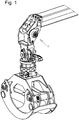
Figure 1 illustrates the position of a swing damper in a rotary joint between a jib and a gripping unit (gripper); -
Figure 2 is an axonometric view of the swing damper at the end of the joint pin; -
Figure 3 is a front view of the swing damper according toFigure 2 ; -
Figure 4 is a longitudinal section of the swing damper along the line A-A according toFigure 3 ; -
Figure 5 illustrates the embodiment of a friction disc having a ring of sector shaped sockets andFigure 6 represents the embodiment of the friction element for the sockets as shown inFigure 5 ; -
Figure 7 shows the embodiment of the friction disc having round sockets and inFigure 8 the embodiment of the friction element for the socket according toFigure 7 is shown; -
Figure 9 illustrates the embodiment of the friction disc comprising a single central socket having a hexagon perimeter andFigure 10 represents the friction element for the socket as shown inFigure 9 ; -
Figure 11 is an axonometric view of an inner pressure disc of the swing damper placed on the joint pin; -
Figure 12 is an axonometric view of an outer pressure disc of the swing damper. - A
swing damper 1 comprises at the end of ajoint pin 2 of a rotary joint twopressure discs joint pin 2. - Both
pressure discs respective pressure discs - Coaxially with
joint pin 2 betweenpressure discs friction disc 5, the rotational motion of which around the longitudinal axis ofjoint pin 2 is fixed in relation to the other half of the rotary joint. -
Friction disc 5 comprises at least onesocket 8 throughfriction disc 5, in which there is afriction element 6 having two parallel flat contact surfaces on opposite sides offriction element 6, that by means of apressure device 7 are on both sides offriction disc 5 pressed into contact with the first andsecond pressure disc -
Friction elements 6 are preferably pressed intosockets 8 with interference fit or fixed by glued joint. This avoids movement of thefriction element 6 relative to the socket. - During operation due to wear or loads the glued joint may become detached and/or interference fit may turn into clearance fit, i.e.
friction elements 6 lie in their respective sockets with clearance. But asfriction elements 6 are pressed by two sides betweenpressure discs friction elements 6 in such a situation cannot fall out ofsockets 8 and the unit still maintains its working condition. - It is seen from the longitudinal section in
Figure 4 that at the end of the joint pin there is formed ashoulder 11, against which rests thefirst pressure disc 3 mounted onjoint pin 2. - On
joint pin 2 there is mountedfriction disc 5 withfriction elements 6 lying in itssockets 8. Thereafter the so-called outersecond pressure disc 4 is pushed ontojoint pin 2. Ontojoint pin 2pressure device 7 is mounted, comprising a package of conical disc springs, which in the present embodiments includes three conical disc springs 9. - Instead disc springs 9 also a spiral compression spring may be used.
- The
pressure nut 10 through anend washer 12 exerts pressure to disc springs 9 and closes saidpressure device 7 when viewed from the end ofjoint pin 2. The other end ofpressure device 7 rests on the outer side ofouter pressure disc 4. - As
inner pressure disc 3 rests onjoint pin 2 againstshoulder 11 at the end ofjoint pin 2, then by tighteningpressure nut 10 thepressure discs friction disc 5 are pressed againstfriction elements 6 in itssockets 8. - The advantage of the use of
shoulder 11 is that upon exerting pressure onpressure discs pressure device 7 againstfriction elements 6 offriction disc 5, the force formed to generate the pressure is not transferred in the longitudinal direction of the joint pin to other elements of the rotary joint. - For operation of
swing damper 1pressure discs retainer bolt 13 to one moving half of the rotary joint so, that the rotational movement ofpressure discs joint pin 2 takes place together with said half of the rotary joint. - The movement of
outer pressure disc 4 is at that fixed by thehead 14 ofretainer bolt 13.Pressure discs respective levers respective bores retainer bolt 13 and itshead 14. -
Friction disc 5 is fixed by means oflever 19 protruding from it and abore 20 at the end oflever 19 relative to the other moving half of the rotary joint such that the rotational movement offriction disc 5 around the longitudinal axis ofjoint pin 2 takes place together with the other moving half of the rotary joint. - When the halves of the rotary joint pivot around the longitudinal axis of
joint pin 2, thenpressure discs joint pin 2 together and between themfriction disc 5 withfriction elements 6 pivots around the longitudinal axis ofjoint pin 2 relative to pressurediscs - Whereas
friction elements 6 are mounted in the sockets offriction disc 5, then rotation offriction disc 5 between the friction elements andpressure discs discs friction disc 5 in relative to pressurediscs 3 and 4 a friction force between them has to be exceeded. Thus pivoting offriction disc 5 relative to pressurediscs - In the earlier
solutions friction elements 6 are not glued tofriction disc 5, the problems associated with the glued joint, such as detachment of glued joint, are entirely avoided. Also it is sufficient during maintenance works to replace only wornfriction elements 6 insockets 8 and instead of replacingfriction disc 5. - Thus it is sufficient to detach
pressure nut 10 from the end ofjoint pin 2 andpressure device 7 together with conical disc springs 9 in it and thewasher 12, after whichouter pressure disc 4 can be pulled away fromfriction elements 6. - Whereas rotation of
friction disc 4 around the longitudinal axis ofjoint pin 2 in relation to the respective side of the rotary joint is prevented only byhead 13 ofretainer bolt 14 in therespective bore 18 oflever 16 ofpressure disc 4, there is no need to unscrewretainer bolt 13. - Thus after detachment of
pressure device 7pressure disc 4 can just be pulled away from the end ofjoint pin 2 and simply theworn friction elements 6 insockets 8 of friction disc can be replaced when necessary. -
Pressure nut 10 at the end ofjoint pin 2 enables easy adjustment of the pressure generated bypressure discs friction elements 6 offriction disc 5 if required. - In
Figures 5 ,7 and9 are shown three different embodiments of thefriction disc 5 and thesockets 8 therein and inFigures 6 ,8 and9 are shown the corresponding embodiments of thefriction elements 6 inserted into thesesockets 8. - In
Figures 5 and 6 there is illustrated an embodiment, wherefriction disc 5 comprisessockets 8 andfriction elements 6 in the shape of a sector of the circle in order to maximize the contact surface betweenplanar friction elements 6 andpressure discs - In
Figures 7 and 8 there is illustrated an embodiment, wherefriction disc 5 comprisescircular sockets 8 andfriction elements 6, which are easiest to manufacture. - In
Figures 9 and 10 there is illustrated an embodiment, wherefriction disc 5 comprises asingle socket 8 for afriction element 6 to be inserted thereto as shown inFigure 10 . - In order to avoid turning of
friction element 6 insocket 8, a perimeter of the socket has the shape of a hexagon. The perimeter offriction disc 6 has also the shape of a hexagon and consequentlyfriction element 6 inserted intosocket 8 cannot rotate. - It is obvious for the person skilled in the art that the present invention is not limited to the embodiments described above and illustrated in the drawings but also other embodiments are possible within the scope of the accompanying claims.
-
- 1
- - swing damper
- 2
- - joint pin
- 3
- - inner pressure disc
- 4
- - outer pressure disc
- 5
- - friction disc
- 6
- - friction element
- 7
- - pressure device
- 8
- - socket
- 9
- - conical disc spring (Belleville spring)
- 10
- - pressure nut
- 11
- - shoulder at the end of the joint pin
- 12
- - end washer
- 13
- - retainer bolt
- 14
- - head of the
retainer bolt 13 - 15
- - lever for fastening
inner pressure disc 3 - 16
- - lever for fastening
outer pressure disc 4 - 17
- - bore for the retainer bolt
- 18
- - bore for the head of retainer bolt
- 19
- - lever for fastening of
friction disc 5 - 20
- - bore at the end of
lever 19
Claims (12)
- A swing damper (1) of a hanging rotary joint, where the swing damper (1) is located at the end of a joint pin (2) of the rotary joint and comprising two pressure discs (3, 4) coaxial with the joint pin (2), where rotational motion of the pressure discs around the longitudinal axis of the joint pin (2) is fixed relative to one pivoting half of the rotary joint, and between the pressure discs (3, 4) there is a friction disc (5) coaxial with the joint pin (2), where rotational motion of the friction disc (5) around the longitudinal axis of the joint pin (2) is fixed relative to the other pivoting half of the rotary joint, the friction disc (5) comprising at least one friction element (6) of the friction material, at the end of the joint pin (2) is a pressure device (7) for pressing the pressure discs (3, 4) against the friction element (6) of the friction disc (5), characterized in that the friction disc (5) comprises at least one socket (8) through the friction disc (5), where the friction element (6) of the friction material is mounted, having two planar contact surfaces on opposite sides of the friction element (6), which on the opposite sides of the frictions disc (5) are pressed into contact with the inner and outer pressure disc (3, 4) respectively by means of the pressure device (7).
- The damper according to claim 1, characterized in that the friction disc (5) comprises several sockets (8) placed symmetrically in relation to the central bore in the friction disc (5), each socket (8) comprising said friction element (6) of the friction material, having a shape corresponding to the shape of the perimeter of the socket.
- The damper according to claim 1, characterized in that the friction disc (5) comprises several circular sockets (8) placed symmetrically in relation to the central bore in the friction disc (5), each socket (8) comprising said friction element (6) of the friction material, having a shape corresponding to the shape of the perimeter of the socket.
- The damper according to claim 1, characterized in that the friction disc (5) comprises several sockets (8) having a shape of a ring sector and mounted symmetrically in relation to the central bore in the friction disc (5), each socket (8) comprising said friction element (6) of the friction material, having a shape corresponding to the shape of the perimeter of the socket.
- The damper according to claim 1, characterized in that the friction disc (5) comprises a single socket (8) of a polygonal shape symmetrical to the centre of the friction disc and in the socket a single friction element (6) of the friction material, having a shape corresponding to the shape of the perimeter of the socket and comprising a through opening in the centre for the joint pin (2).
- The damper according to any of previous claims, characterized in that the pressure device (7) comprises on the joint pin a conical disc spring package comprising at least one conical disc spring (9), by which pressure is generated from the end of the joint pin to press the friction disc (5) between the two pressure discs (3, 4).
- The damper according to claim 6, characterized in that the conical disc spring package of the pressure device (7) comprises three conical disc springs (9).
- The damper according to any of previous claims 6 or 7, characterized in that the pressure device (7) comprises at the end of the joint pin (2) a pressure nut (10), by means of which the pressure of the pressure discs (3, 4) generated by the conical disc spring package against at least one friction element (6) of the friction disc (5) can be adjusted.
- The damper according to any of previous claims 1 to 5, characterized in that the pressure device (7) comprises on the joint pin (2) a spiral spring by which from the end of the joint pin pressure is generated to press the friction disc (5) between the two pressure discs (3, 4).
- The damper according to claim 9, characterized in that the pressure device (7) comprises at the end of the joint pin (2) a pressure nut (10), by means of which the pressure of the pressure discs (3, 4) generated by the spiral spring against at least one friction element (6) of the friction disc (5) can be adjusted.
- The damper according to any of previous claims, characterized in that the friction elements (6) have been mounted into the sockets (8) by clearance fit.
- The damper according to any of previous claims, characterized in that the friction elements (6) have been fixed into the sockets (8) by glued joint.
Priority Applications (2)
| Application Number | Priority Date | Filing Date | Title |
|---|---|---|---|
| SI201830006T SI3409634T1 (en) | 2017-05-29 | 2018-04-06 | Swing damper of a hanging rotary joint |
| PL18166027T PL3409634T3 (en) | 2017-05-29 | 2018-04-06 | Swing damper of a hanging rotary joint |
Applications Claiming Priority (1)
| Application Number | Priority Date | Filing Date | Title |
|---|---|---|---|
| EEU201700027U EE01456U1 (en) | 2017-05-29 | 2017-05-29 | Swing swing damper |
Publications (3)
| Publication Number | Publication Date |
|---|---|
| EP3409634A1 true EP3409634A1 (en) | 2018-12-05 |
| EP3409634A8 EP3409634A8 (en) | 2019-02-20 |
| EP3409634B1 EP3409634B1 (en) | 2019-07-03 |
Family
ID=61911463
Family Applications (1)
| Application Number | Title | Priority Date | Filing Date |
|---|---|---|---|
| EP18166027.5A Active EP3409634B1 (en) | 2017-05-29 | 2018-04-06 | Swing damper of a hanging rotary joint |
Country Status (4)
| Country | Link |
|---|---|
| EP (1) | EP3409634B1 (en) |
| EE (1) | EE01456U1 (en) |
| PL (1) | PL3409634T3 (en) |
| SI (1) | SI3409634T1 (en) |
Cited By (2)
| Publication number | Priority date | Publication date | Assignee | Title |
|---|---|---|---|---|
| CN116923715A (en) * | 2022-04-06 | 2023-10-24 | 海鹰航空通用装备有限责任公司 | Arresting hook centering device |
| EP4650315A1 (en) | 2024-05-14 | 2025-11-19 | Konrad Lechner | Pendulum joint for the attachment of hydraulically actuated working devices |
Citations (3)
| Publication number | Priority date | Publication date | Assignee | Title |
|---|---|---|---|---|
| US5110169A (en) | 1990-10-03 | 1992-05-05 | Deere & Company | Grease loaded grapple dampener |
| WO2000053522A1 (en) * | 1999-03-09 | 2000-09-14 | Indexator Ab | Arrangement and method relating to a swing damper |
| WO2004031067A1 (en) | 2002-10-07 | 2004-04-15 | Indexator Ab | Arrangement related to a swing damper |
-
2017
- 2017-05-29 EE EEU201700027U patent/EE01456U1/en active Protection Beyond IP Right Term
-
2018
- 2018-04-06 SI SI201830006T patent/SI3409634T1/en unknown
- 2018-04-06 EP EP18166027.5A patent/EP3409634B1/en active Active
- 2018-04-06 PL PL18166027T patent/PL3409634T3/en unknown
Patent Citations (3)
| Publication number | Priority date | Publication date | Assignee | Title |
|---|---|---|---|---|
| US5110169A (en) | 1990-10-03 | 1992-05-05 | Deere & Company | Grease loaded grapple dampener |
| WO2000053522A1 (en) * | 1999-03-09 | 2000-09-14 | Indexator Ab | Arrangement and method relating to a swing damper |
| WO2004031067A1 (en) | 2002-10-07 | 2004-04-15 | Indexator Ab | Arrangement related to a swing damper |
Cited By (3)
| Publication number | Priority date | Publication date | Assignee | Title |
|---|---|---|---|---|
| CN116923715A (en) * | 2022-04-06 | 2023-10-24 | 海鹰航空通用装备有限责任公司 | Arresting hook centering device |
| CN116923715B (en) * | 2022-04-06 | 2026-04-14 | 海鹰航空通用装备有限责任公司 | A centering device for a blocking hook |
| EP4650315A1 (en) | 2024-05-14 | 2025-11-19 | Konrad Lechner | Pendulum joint for the attachment of hydraulically actuated working devices |
Also Published As
| Publication number | Publication date |
|---|---|
| EP3409634B1 (en) | 2019-07-03 |
| SI3409634T1 (en) | 2019-11-29 |
| EP3409634A8 (en) | 2019-02-20 |
| EE01456U1 (en) | 2019-02-15 |
| PL3409634T3 (en) | 2020-06-01 |
Similar Documents
| Publication | Publication Date | Title |
|---|---|---|
| US7721857B2 (en) | Arrangement related to a swing damper | |
| CN111032376B (en) | Center joint for three-point link | |
| CN102943495B (en) | Hinge mechanism | |
| CN103233991A (en) | Disk brake and adjusting device for a disk brake | |
| EP3409634B1 (en) | Swing damper of a hanging rotary joint | |
| RU2668834C2 (en) | Ball-jointed device for suspending a turbomachine from a pylon or for suspending equipment from the body of the turbomachine | |
| US10507850B2 (en) | Device for connecting a coupling shaft to a car body of a track-guided vehicle | |
| US9067764B2 (en) | Swing damper with disc brakes | |
| CA2015689C (en) | Pre-loading pivotal pin connection for a disc brake assembly | |
| US20130193663A1 (en) | Suspension assembly for an automotive vehicle and automotive vehicle comprising such a suspension assembly | |
| US20140027222A1 (en) | Swing damper with disc brakes and its control mechanism | |
| CN114833561A (en) | Arrangement of a fastening device and a safety device for a threaded connection | |
| CN104500522B (en) | Double-nut locking mechanism | |
| FI116136B (en) | Swivel clutch for load grippers | |
| CN203611673U (en) | Steel plate spring fixing mechanism | |
| CN219792309U (en) | Winding engine holding clutch mechanism | |
| EP2704976B1 (en) | Swing damper with disc brakes and its control mechanism | |
| EP2437998B1 (en) | Tensioning element | |
| US9982731B2 (en) | Disc brake apparatus | |
| US12000430B2 (en) | Joint element provided with swing dampener brake, joint assembly comprising the joint element, and machine comprising the joint assembly | |
| EP3463768B1 (en) | Spring balancing device and industrial robot comprising a spring balancing device | |
| USH2012H1 (en) | Braked joint assembly | |
| WO2000073195A1 (en) | Method and arrangement relating to a swing damper | |
| CN220283417U (en) | A kind of outrigger device and engineering machinery | |
| BR112021009026B1 (en) | JOINT ELEMENT EQUIPPED WITH OSCILLATION DAMPER BRAKE, JOINT ASSEMBLY COMPRISING THE JOINT ELEMENT AND MACHINE COMPRISING THE JOINT ASSEMBLY |
Legal Events
| Date | Code | Title | Description |
|---|---|---|---|
| PUAI | Public reference made under article 153(3) epc to a published international application that has entered the european phase |
Free format text: ORIGINAL CODE: 0009012 |
|
| STAA | Information on the status of an ep patent application or granted ep patent |
Free format text: STATUS: THE APPLICATION HAS BEEN PUBLISHED |
|
| AK | Designated contracting states |
Kind code of ref document: A1 Designated state(s): AL AT BE BG CH CY CZ DE DK EE ES FI FR GB GR HR HU IE IS IT LI LT LU LV MC MK MT NL NO PL PT RO RS SE SI SK SM TR |
|
| AX | Request for extension of the european patent |
Extension state: BA ME |
|
| RAP1 | Party data changed (applicant data changed or rights of an application transferred) |
Owner name: OUE PALMSE MEHAANIKAKODA |
|
| STAA | Information on the status of an ep patent application or granted ep patent |
Free format text: STATUS: REQUEST FOR EXAMINATION WAS MADE |
|
| 17P | Request for examination filed |
Effective date: 20190218 |
|
| RBV | Designated contracting states (corrected) |
Designated state(s): AL AT BE BG CH CY CZ DE DK EE ES FI FR GB GR HR HU IE IS IT LI LT LU LV MC MK MT NL NO PL PT RO RS SE SI SK SM TR |
|
| GRAP | Despatch of communication of intention to grant a patent |
Free format text: ORIGINAL CODE: EPIDOSNIGR1 |
|
| STAA | Information on the status of an ep patent application or granted ep patent |
Free format text: STATUS: GRANT OF PATENT IS INTENDED |
|
| RIC1 | Information provided on ipc code assigned before grant |
Ipc: E02F 3/36 20060101ALI20190403BHEP Ipc: E02F 9/00 20060101ALI20190403BHEP Ipc: F16F 7/04 20060101ALI20190403BHEP Ipc: B66C 3/00 20060101AFI20190403BHEP |
|
| INTG | Intention to grant announced |
Effective date: 20190424 |
|
| GRAS | Grant fee paid |
Free format text: ORIGINAL CODE: EPIDOSNIGR3 |
|
| GRAA | (expected) grant |
Free format text: ORIGINAL CODE: 0009210 |
|
| STAA | Information on the status of an ep patent application or granted ep patent |
Free format text: STATUS: THE PATENT HAS BEEN GRANTED |
|
| AK | Designated contracting states |
Kind code of ref document: B1 Designated state(s): AL AT BE BG CH CY CZ DE DK EE ES FI FR GB GR HR HU IE IS IT LI LT LU LV MC MK MT NL NO PL PT RO RS SE SI SK SM TR |
|
| REG | Reference to a national code |
Ref country code: GB Ref legal event code: FG4D |
|
| REG | Reference to a national code |
Ref country code: CH Ref legal event code: EP Ref country code: AT Ref legal event code: REF Ref document number: 1150762 Country of ref document: AT Kind code of ref document: T Effective date: 20190715 |
|
| REG | Reference to a national code |
Ref country code: IE Ref legal event code: FG4D |
|
| REG | Reference to a national code |
Ref country code: DE Ref legal event code: R096 Ref document number: 602018000206 Country of ref document: DE |
|
| REG | Reference to a national code |
Ref country code: NL Ref legal event code: MP Effective date: 20190703 |
|
| REG | Reference to a national code |
Ref country code: LT Ref legal event code: MG4D |
|
| PG25 | Lapsed in a contracting state [announced via postgrant information from national office to epo] |
Ref country code: PT Free format text: LAPSE BECAUSE OF FAILURE TO SUBMIT A TRANSLATION OF THE DESCRIPTION OR TO PAY THE FEE WITHIN THE PRESCRIBED TIME-LIMIT Effective date: 20191104 Ref country code: NO Free format text: LAPSE BECAUSE OF FAILURE TO SUBMIT A TRANSLATION OF THE DESCRIPTION OR TO PAY THE FEE WITHIN THE PRESCRIBED TIME-LIMIT Effective date: 20191003 Ref country code: BG Free format text: LAPSE BECAUSE OF FAILURE TO SUBMIT A TRANSLATION OF THE DESCRIPTION OR TO PAY THE FEE WITHIN THE PRESCRIBED TIME-LIMIT Effective date: 20191003 Ref country code: SE Free format text: LAPSE BECAUSE OF FAILURE TO SUBMIT A TRANSLATION OF THE DESCRIPTION OR TO PAY THE FEE WITHIN THE PRESCRIBED TIME-LIMIT Effective date: 20190703 Ref country code: CZ Free format text: LAPSE BECAUSE OF FAILURE TO SUBMIT A TRANSLATION OF THE DESCRIPTION OR TO PAY THE FEE WITHIN THE PRESCRIBED TIME-LIMIT Effective date: 20190703 Ref country code: NL Free format text: LAPSE BECAUSE OF FAILURE TO SUBMIT A TRANSLATION OF THE DESCRIPTION OR TO PAY THE FEE WITHIN THE PRESCRIBED TIME-LIMIT Effective date: 20190703 Ref country code: HR Free format text: LAPSE BECAUSE OF FAILURE TO SUBMIT A TRANSLATION OF THE DESCRIPTION OR TO PAY THE FEE WITHIN THE PRESCRIBED TIME-LIMIT Effective date: 20190703 Ref country code: LT Free format text: LAPSE BECAUSE OF FAILURE TO SUBMIT A TRANSLATION OF THE DESCRIPTION OR TO PAY THE FEE WITHIN THE PRESCRIBED TIME-LIMIT Effective date: 20190703 |
|
| PG25 | Lapsed in a contracting state [announced via postgrant information from national office to epo] |
Ref country code: IS Free format text: LAPSE BECAUSE OF FAILURE TO SUBMIT A TRANSLATION OF THE DESCRIPTION OR TO PAY THE FEE WITHIN THE PRESCRIBED TIME-LIMIT Effective date: 20191103 Ref country code: LV Free format text: LAPSE BECAUSE OF FAILURE TO SUBMIT A TRANSLATION OF THE DESCRIPTION OR TO PAY THE FEE WITHIN THE PRESCRIBED TIME-LIMIT Effective date: 20190703 Ref country code: RS Free format text: LAPSE BECAUSE OF FAILURE TO SUBMIT A TRANSLATION OF THE DESCRIPTION OR TO PAY THE FEE WITHIN THE PRESCRIBED TIME-LIMIT Effective date: 20190703 Ref country code: GR Free format text: LAPSE BECAUSE OF FAILURE TO SUBMIT A TRANSLATION OF THE DESCRIPTION OR TO PAY THE FEE WITHIN THE PRESCRIBED TIME-LIMIT Effective date: 20191004 Ref country code: ES Free format text: LAPSE BECAUSE OF FAILURE TO SUBMIT A TRANSLATION OF THE DESCRIPTION OR TO PAY THE FEE WITHIN THE PRESCRIBED TIME-LIMIT Effective date: 20190703 Ref country code: AL Free format text: LAPSE BECAUSE OF FAILURE TO SUBMIT A TRANSLATION OF THE DESCRIPTION OR TO PAY THE FEE WITHIN THE PRESCRIBED TIME-LIMIT Effective date: 20190703 |
|
| PG25 | Lapsed in a contracting state [announced via postgrant information from national office to epo] |
Ref country code: TR Free format text: LAPSE BECAUSE OF FAILURE TO SUBMIT A TRANSLATION OF THE DESCRIPTION OR TO PAY THE FEE WITHIN THE PRESCRIBED TIME-LIMIT Effective date: 20190703 |
|
| PG25 | Lapsed in a contracting state [announced via postgrant information from national office to epo] |
Ref country code: EE Free format text: LAPSE BECAUSE OF FAILURE TO SUBMIT A TRANSLATION OF THE DESCRIPTION OR TO PAY THE FEE WITHIN THE PRESCRIBED TIME-LIMIT Effective date: 20190703 Ref country code: DK Free format text: LAPSE BECAUSE OF FAILURE TO SUBMIT A TRANSLATION OF THE DESCRIPTION OR TO PAY THE FEE WITHIN THE PRESCRIBED TIME-LIMIT Effective date: 20190703 Ref country code: IT Free format text: LAPSE BECAUSE OF FAILURE TO SUBMIT A TRANSLATION OF THE DESCRIPTION OR TO PAY THE FEE WITHIN THE PRESCRIBED TIME-LIMIT Effective date: 20190703 Ref country code: RO Free format text: LAPSE BECAUSE OF FAILURE TO SUBMIT A TRANSLATION OF THE DESCRIPTION OR TO PAY THE FEE WITHIN THE PRESCRIBED TIME-LIMIT Effective date: 20190703 |
|
| PG25 | Lapsed in a contracting state [announced via postgrant information from national office to epo] |
Ref country code: IS Free format text: LAPSE BECAUSE OF FAILURE TO SUBMIT A TRANSLATION OF THE DESCRIPTION OR TO PAY THE FEE WITHIN THE PRESCRIBED TIME-LIMIT Effective date: 20200224 Ref country code: SM Free format text: LAPSE BECAUSE OF FAILURE TO SUBMIT A TRANSLATION OF THE DESCRIPTION OR TO PAY THE FEE WITHIN THE PRESCRIBED TIME-LIMIT Effective date: 20190703 Ref country code: SK Free format text: LAPSE BECAUSE OF FAILURE TO SUBMIT A TRANSLATION OF THE DESCRIPTION OR TO PAY THE FEE WITHIN THE PRESCRIBED TIME-LIMIT Effective date: 20190703 |
|
| REG | Reference to a national code |
Ref country code: DE Ref legal event code: R097 Ref document number: 602018000206 Country of ref document: DE |
|
| PLBE | No opposition filed within time limit |
Free format text: ORIGINAL CODE: 0009261 |
|
| STAA | Information on the status of an ep patent application or granted ep patent |
Free format text: STATUS: NO OPPOSITION FILED WITHIN TIME LIMIT |
|
| PG2D | Information on lapse in contracting state deleted |
Ref country code: IS |
|
| 26N | No opposition filed |
Effective date: 20200603 |
|
| PG25 | Lapsed in a contracting state [announced via postgrant information from national office to epo] |
Ref country code: MC Free format text: LAPSE BECAUSE OF FAILURE TO SUBMIT A TRANSLATION OF THE DESCRIPTION OR TO PAY THE FEE WITHIN THE PRESCRIBED TIME-LIMIT Effective date: 20190703 |
|
| PG25 | Lapsed in a contracting state [announced via postgrant information from national office to epo] |
Ref country code: LU Free format text: LAPSE BECAUSE OF NON-PAYMENT OF DUE FEES Effective date: 20200406 |
|
| REG | Reference to a national code |
Ref country code: BE Ref legal event code: MM Effective date: 20200430 |
|
| PG25 | Lapsed in a contracting state [announced via postgrant information from national office to epo] |
Ref country code: BE Free format text: LAPSE BECAUSE OF NON-PAYMENT OF DUE FEES Effective date: 20200430 |
|
| PG25 | Lapsed in a contracting state [announced via postgrant information from national office to epo] |
Ref country code: IE Free format text: LAPSE BECAUSE OF NON-PAYMENT OF DUE FEES Effective date: 20200406 |
|
| PG25 | Lapsed in a contracting state [announced via postgrant information from national office to epo] |
Ref country code: LI Free format text: LAPSE BECAUSE OF NON-PAYMENT OF DUE FEES Effective date: 20210430 Ref country code: CH Free format text: LAPSE BECAUSE OF NON-PAYMENT OF DUE FEES Effective date: 20210430 |
|
| REG | Reference to a national code |
Ref country code: AT Ref legal event code: UEP Ref document number: 1150762 Country of ref document: AT Kind code of ref document: T Effective date: 20190703 |
|
| PG25 | Lapsed in a contracting state [announced via postgrant information from national office to epo] |
Ref country code: MT Free format text: LAPSE BECAUSE OF FAILURE TO SUBMIT A TRANSLATION OF THE DESCRIPTION OR TO PAY THE FEE WITHIN THE PRESCRIBED TIME-LIMIT Effective date: 20190703 Ref country code: CY Free format text: LAPSE BECAUSE OF FAILURE TO SUBMIT A TRANSLATION OF THE DESCRIPTION OR TO PAY THE FEE WITHIN THE PRESCRIBED TIME-LIMIT Effective date: 20190703 |
|
| PG25 | Lapsed in a contracting state [announced via postgrant information from national office to epo] |
Ref country code: MK Free format text: LAPSE BECAUSE OF FAILURE TO SUBMIT A TRANSLATION OF THE DESCRIPTION OR TO PAY THE FEE WITHIN THE PRESCRIBED TIME-LIMIT Effective date: 20190703 |
|
| GBPC | Gb: european patent ceased through non-payment of renewal fee |
Effective date: 20220406 |
|
| PG25 | Lapsed in a contracting state [announced via postgrant information from national office to epo] |
Ref country code: GB Free format text: LAPSE BECAUSE OF NON-PAYMENT OF DUE FEES Effective date: 20220406 |
|
| P01 | Opt-out of the competence of the unified patent court (upc) registered |
Effective date: 20230530 |
|
| PGFP | Annual fee paid to national office [announced via postgrant information from national office to epo] |
Ref country code: SI Payment date: 20250317 Year of fee payment: 8 |
|
| PGFP | Annual fee paid to national office [announced via postgrant information from national office to epo] |
Ref country code: DE Payment date: 20250428 Year of fee payment: 8 |
|
| PGFP | Annual fee paid to national office [announced via postgrant information from national office to epo] |
Ref country code: FR Payment date: 20250424 Year of fee payment: 8 |
|
| PGFP | Annual fee paid to national office [announced via postgrant information from national office to epo] |
Ref country code: AT Payment date: 20250417 Year of fee payment: 8 |
|
| PGFP | Annual fee paid to national office [announced via postgrant information from national office to epo] |
Ref country code: FI Payment date: 20260326 Year of fee payment: 9 |
|
| PGFP | Annual fee paid to national office [announced via postgrant information from national office to epo] |
Ref country code: PL Payment date: 20260326 Year of fee payment: 9 |