EP3409617A1 - Packaging for a fluid filter element, packaging arrangement - Google Patents
Packaging for a fluid filter element, packaging arrangement Download PDFInfo
- Publication number
- EP3409617A1 EP3409617A1 EP18174539.9A EP18174539A EP3409617A1 EP 3409617 A1 EP3409617 A1 EP 3409617A1 EP 18174539 A EP18174539 A EP 18174539A EP 3409617 A1 EP3409617 A1 EP 3409617A1
- Authority
- EP
- European Patent Office
- Prior art keywords
- filter element
- packaging
- fluid filter
- fluid
- funnel
- Prior art date
- Legal status (The legal status is an assumption and is not a legal conclusion. Google has not performed a legal analysis and makes no representation as to the accuracy of the status listed.)
- Granted
Links
Images




Classifications
-
- B—PERFORMING OPERATIONS; TRANSPORTING
- B65—CONVEYING; PACKING; STORING; HANDLING THIN OR FILAMENTARY MATERIAL
- B65D—CONTAINERS FOR STORAGE OR TRANSPORT OF ARTICLES OR MATERIALS, e.g. BAGS, BARRELS, BOTTLES, BOXES, CANS, CARTONS, CRATES, DRUMS, JARS, TANKS, HOPPERS, FORWARDING CONTAINERS; ACCESSORIES, CLOSURES, OR FITTINGS THEREFOR; PACKAGING ELEMENTS; PACKAGES
- B65D81/00—Containers, packaging elements, or packages, for contents presenting particular transport or storage problems, or adapted to be used for non-packaging purposes after removal of contents
- B65D81/36—Containers, packaging elements, or packages, for contents presenting particular transport or storage problems, or adapted to be used for non-packaging purposes after removal of contents adapted to be used for non-packaging purposes after removal of contents
-
- B—PERFORMING OPERATIONS; TRANSPORTING
- B65—CONVEYING; PACKING; STORING; HANDLING THIN OR FILAMENTARY MATERIAL
- B65D—CONTAINERS FOR STORAGE OR TRANSPORT OF ARTICLES OR MATERIALS, e.g. BAGS, BARRELS, BOTTLES, BOXES, CANS, CARTONS, CRATES, DRUMS, JARS, TANKS, HOPPERS, FORWARDING CONTAINERS; ACCESSORIES, CLOSURES, OR FITTINGS THEREFOR; PACKAGING ELEMENTS; PACKAGES
- B65D75/00—Packages comprising articles or materials partially or wholly enclosed in strips, sheets, blanks, tubes or webs of flexible sheet material, e.g. in folded wrappers
- B65D75/28—Articles or materials wholly enclosed in composite wrappers, i.e. wrappers formed by associating or interconnecting two or more sheets or blanks
- B65D75/30—Articles or materials enclosed between two opposed sheets or blanks having their margins united, e.g. by pressure-sensitive adhesive, crimping, heat-sealing, or welding
- B65D75/32—Articles or materials enclosed between two opposed sheets or blanks having their margins united, e.g. by pressure-sensitive adhesive, crimping, heat-sealing, or welding one or both sheets or blanks being recessed to accommodate contents
- B65D75/321—Both sheets being recessed
- B65D75/322—Both sheets being recessed and forming one compartment
-
- B—PERFORMING OPERATIONS; TRANSPORTING
- B65—CONVEYING; PACKING; STORING; HANDLING THIN OR FILAMENTARY MATERIAL
- B65D—CONTAINERS FOR STORAGE OR TRANSPORT OF ARTICLES OR MATERIALS, e.g. BAGS, BARRELS, BOTTLES, BOXES, CANS, CARTONS, CRATES, DRUMS, JARS, TANKS, HOPPERS, FORWARDING CONTAINERS; ACCESSORIES, CLOSURES, OR FITTINGS THEREFOR; PACKAGING ELEMENTS; PACKAGES
- B65D85/00—Containers, packaging elements or packages, specially adapted for particular articles or materials
- B65D85/68—Containers, packaging elements or packages, specially adapted for particular articles or materials for machines, engines or vehicles in assembled or dismantled form
-
- B—PERFORMING OPERATIONS; TRANSPORTING
- B65—CONVEYING; PACKING; STORING; HANDLING THIN OR FILAMENTARY MATERIAL
- B65D—CONTAINERS FOR STORAGE OR TRANSPORT OF ARTICLES OR MATERIALS, e.g. BAGS, BARRELS, BOTTLES, BOXES, CANS, CARTONS, CRATES, DRUMS, JARS, TANKS, HOPPERS, FORWARDING CONTAINERS; ACCESSORIES, CLOSURES, OR FITTINGS THEREFOR; PACKAGING ELEMENTS; PACKAGES
- B65D2585/00—Containers, packaging elements or packages specially adapted for particular articles or materials
- B65D2585/68—Containers, packaging elements or packages specially adapted for particular articles or materials for machines, engines, or vehicles in assembled or dismantled form
- B65D2585/6802—Containers, packaging elements or packages specially adapted for particular articles or materials for machines, engines, or vehicles in assembled or dismantled form specific machines, engines or vehicles
- B65D2585/6875—Containers, packaging elements or packages specially adapted for particular articles or materials for machines, engines, or vehicles in assembled or dismantled form specific machines, engines or vehicles engines, motors, machines and vehicle parts
- B65D2585/6882—Containers, packaging elements or packages specially adapted for particular articles or materials for machines, engines, or vehicles in assembled or dismantled form specific machines, engines or vehicles engines, motors, machines and vehicle parts vehicle parts
Definitions
- the invention relates to a packaging for a fluid filter element, preferably of the type employed in filtering oil or fuel for an automotive or motorcycle engine, comprising at least a first packaging part and a second packaging part, wherein the first packaging part and the second packaging part can cooperate to define a receiving chamber for receiving therein a fluid filter element.
- the invention further relates to a packaging arrangement comprising such a packaging.
- Fluid filter elements are subject to wear and generally need to be replaced at certain maintenance intervals. New and unused fluid filter elements used for replacement are usually provided in so-called blister packs and/or cardboard boxes.
- a particular problem during replacement of a fluid filter element arises from the fact that the used fluid filter element that is to be replaced usually contains residual fluid, e.g. residual oil or fuel. Often, the said residual fluid is decanted into the replacement fluid filter element during replacement of the filter element. This, however, often leads to an unwanted spilling of the fluid and contamination of the surrounding. Further, the used fluid filter element as well as the residual fluid contained therein should be disposed properly to reduce environmental risks associated therewith.
- a packaging for the transport and storage of a fluid filter element is disclosed, for instance, in WO 92/18397 .
- the known packaging is of a liquid-tight design. It can be reclosed after opening, so that a used, respectively old, fluid filter element with residual fluid still contained therein can be repacked into the liquid-tight packaging and sent back to a manufacturer or an appropriate disposer.
- a further packaging for a fluid filter element is known from US 3,710,930 .
- the packaging provides a support shell.
- the support shell can be employed as a hand-tool in removing a spent fluid filter element from a heated engine.
- the object of the invention is to provide an improved packaging and packaging arrangement for a fluid filter element.
- a further object of the invention is to provide an improved method for replacing a, preferably used, fluid filter element by an unused fluid filter element provided in an aforementioned packaging.
- the object of the invention concerning the packaging is solved by a packaging according to claim 1.
- a packaging arrangement according to the invention is given in claim 10.
- the method for replacement of a fluid filter element is given in claim 13.
- Preferred embodiments of the invention are given in the dependent claims and the description.
- the packaging for a fluid filter element preferably of the type employed in filtering oil or fuel, in particular of an automotive or motorcycle engine, comprises at least a first packaging part and a second packaging part.
- the first packaging part and the second packaging part can be adapted to cooperate to define a receiving chamber for receiving therein the fluid filter element.
- the packaging preferably the first packaging part, comprises a funnel for filling the fluid filter element with fluid.
- the funnel preferably has a first orifice serving as funnel inlet and one or more second orifices serving as funnel outlets.
- the funnel further has a connecting pipe section on which the second orifice serving as a funnel outlet is present.
- the connecting pipe section is adapted to be sealingly connected with an inlet of said filter element, so that none of the fluid that is being fed through the funnel is spilled. This can be done in a clean and easy fashion without spilling of fluid or the need for a specific tooling equipment. Even if the residual fluid transferred from the used filter element contains contaminants such as particulate matter, the absolute quantity of residual fluid usually is sufficiently small such that no significant adverse effects to the new fluid filter element or other parts to be supplied with filtered fluid, e.g. a combustion engine, are to be expected.
- the packaging according to the invention thus serves both as a protective cover for the new fluid filter element during transport or storage and as a, preferably single-use, maintenance tool for replacing the used fluid filter element with the new fluid filter element. Moreover, the packaging according to the invention helps protect the environment as residual fluid is not dispensed into the environment but can be kept safely within the new fluid filter element until the new fluid filter element is put to use.
- the manufacturing of the funnel does not require any additional, costly manufacturing steps in addition to the manufacturing, e.g. injection-molding, of the first packaging part.
- the packaging preferably the second packaging part, comprises or forms a stand for positioning and holding the fluid filter element in an upright position or an essentially upright position.
- An "upright position” is understood to mean a position of the fluid filter element in which fluid can be poured into the fluid filter element through an inlet of the fluid filter element.
- Bottom and bottom side refer to the lower part, respectively, the bottom side of the fluid filter element being positioned in its upright position.
- top and “top side” refer to the upper part, respectively, the top side of the fluid filter element being positioned in its upright position.
- Most off-the-shelf fluid filter elements cannot remain in an upright position when placed on a surface, e.g. a table top or the ground. This is because their bottom is usually not flat, but e.g. rounded and/or has projections at the bottom thereof.
- the stand allows to reliably position and hold the filter element in an upright position as needed for filling (the residual) fluid into the filter element.
- the stand may be at least partially formed ring-shaped, in particular cylindrically or conically.
- the cross-sectional shape of the stand can be circular for instance.
- the packaging in particular the funnel, may, therefore, comprise a plug for sealing off a clean side outlet of the fluid filter element during filling thereof.
- the plug preferably is present on or at the connecting pipe section of the funnel; in particular it can be formed as a closed axial end or wall of the same.
- the plug is preferably directly molded onto or formed by the funnel, e.g. an outlet spigot thereof. Thereby, the plug can be automatically inserted/plugged into the clean side outlet of the fluid filter which needs to be filled, as soon as the funnel is placed onto the fluid filter element's inlet.
- the funnel in particular an outlet spigot of the funnel, in this case, preferably has lateral openings and a blind end.
- the residual fluid may be introduced into the raw side of the filter element while the fluid filter element's clean side is protected from potentially contaminated residual fluid of the filter element which needs to be replaced.
- the second packaging part may have a bowl-shaped or an essentially bowl-shaped form.
- the fluid filter element can be inserted into the second packaging part for transport and/or storage.
- the bowl-shaped second packaging part according to the invention, can be designed as a self-supporting structure which can stand in an upright position by itself.
- the second packaging part may be designed and adapted to support the fluid filter element in an upright position for decanting residual fluid from another filter element therein.
- the second packaging part in other words, may be designed as a support or stand for the fluid filter element.
- the second packaging part may have a plane end for positioning the second packaging part on a suitable surface, e.g. a table top or the ground.
- the second packaging part also has a double function. Thereby, unnecessary additional manufacturing steps or costs incurred when providing a separate stand for the fluid filter element are avoided.
- the first and the second packaging part preferably form a blister packaging for the filter element.
- the first and second packaging parts each may have a ring shoulder or flange which project in a radial direction, preferably outwards, from the respective packaging part and which abut against each other when the blister packaging is closed.
- the first packaging part and/or the second packaging part may have at least one fastening means by which the first packaging part and the second packaging part may be detachably fastened to one another.
- a filter element When a filter element is positioned inside the blister packaging, it may thereby be protected against coarse contaminants.
- the packaging may have additional sealing means by which the receiving chamber may be sealed off against the outside.
- a fluid filter element placed inside the receiving chamber may be protected hermetically against contamination.
- the fluid filter element is filled with a fluid, e. g. a residual fluid, the fluid cannot leak out of the receiving chamber.
- the sealing means may comprise a sealing ring of rubber or elastomeric material which is arranged, in particular molded onto, one of the flanges of the first or second packaging part.
- the first packaging part and/or the second packaging part may be made of a plastic material, in particular a thermoplastic such as, for instance, polypropylene, polyethylene or polymethylpentene.
- the first and/or the second packaging part may be stiff and/or bending-resistant and may have a thickness between 0.2 and 2 mm.
- first packaging part and/or the second packaging part can be made of paper and/or cardboard or a combination thereof.
- the paper and/or cardboard can also be impregnated in order to achieve a greater resistance to the fluid to be filled into the filter element, e.g. fuel, in particular diesel fuel.
- other materials that have a similar resistance to said fluids can be used to form the first packaging part and/or the second packaging part, e.g. metals.
- the packaging arrangement comprises a packaging according to the invention and a fluid filter element wherein the fluid filter element is received in the receiving chamber of the packaging.
- the funnel is installed on the fluid filter element, preferably partially inserted into, e.g. an inlet, of the fluid filter element.
- the funnel may be pre-installed, for example by a manufacturer of the packaging arrangement, on the fluid filter element.
- the inlet may preferably be the raw side inlet of the fluid filter element.
- the aforementioned funnel may comprise or form at least one air exit allowing air to exit the fluid filter element while fluid is poured thereinto.
- the air exit may comprise one or more grooves formed on the funnel.
- the funnel may be connected to a raw side inlet of the fluid filter element.
- the funnel's outlet may open in a direction perpendicular or essentially perpendicular to the longitudinal axis of the fluid filter element.
- the funnel is provided with one or more radial or lateral orifices to thereby allow a fluid flow directly to the raw side inlet of a filter element.
- the method for replacing a first, preferably used, fluid filter element by a second, preferably unused, fluid filter element provided in a packaging according to the invention comprises the following steps:
- the residual fluid contained in the filter element which needs to be replaced can thus be introduced into the unused fluid filter element without any additional tool, e.g. a separate funnel, which needs to be provided and cleaned after use.
- the first fluid filter element may be emptied and the residual fluid may be disposed in a very easy, clean, and ecofriendly way.
- the funnel is preferably pre-installed, particularly by a manufacturer of the fluid filter element and/or the packaging, on the second fluid filter element.
- the second fluid filter element does not need to be unpacked from the packaging.
- the fluid filter element can be unpacked from the packaging before connecting the funnel to the inlet of the second fluid filter element.
- the method further comprises the step of using the second packaging part of the packaging or another packaging part as a stand for positioning and holding the unused fluid filter element in an upright position.
- the stand for holding the second fluid filter element in an upright position may be pre-installed at the bottom of the second fluid filter element. In this way, the second fluid filter element may already be safely positioned within e.g. a cardboard box or carton, in particular for transportation purposes.
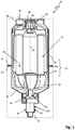
- FIG. 1 shows a packaging arrangement 10 comprising a packaging 12 and a first fluid filter element 14 contained therein.
- the packaging 12 serves as protective cover of the first fluid filter element 14 during transport and storage.
- the packaging 10 has a two-part design and comprises a first packaging part 16 and a second packaging part 18.
- the first and the second packaging parts 16, 18 cooperate to provide a receiving chamber 20 for the fluid filter element 14.
- the first and second packaging parts both may have a, preferably ring-shaped, flange 22 which projects in a radial direction from the respective packaging part 16, 18 with respect to a longitudinal axis 24 of the package arrangement 10 or packaging 12, respectively.
- the flanges 22 abut against each other and serve for an attachment of the two packaging parts 16, 18 to one another.
- the first packaging part 16 forms a funnel 26.
- the funnel 26 has a first (inlet) orifice 28, several second lateral (outlet) orifices 30 and a plug 32 as shall be explained in further detail below.
- the second orifices 30 are present on a connecting pipe section of the funnel 26 that is axially extending and formed in one piece with the funnel 26.
- the connecting pipe section 300 is dimensioned so as to fit properly sealingly into on inlet 40 of the filter element 14.
- the connecting pipe section 300 can be adapted to be sealingly connected to an outlet of the filter element 14; this actually depends on the internal structure of the filter element 14.
- the connecting pipe section 300 can of course have less openings 30, e.g. only one and is embodied as a fluidic socket or fitting.
- the second packaging part 18 is generally bowl-shaped. It comprises a cylindrical end section which forms a stand 34.
- the stand 34 may have a flat face 36 which is perpendicularly arranged in relation to the longitudinal axis 24 of the package arrangement 10.
- the fluid filter element 14 has a top end 38 with a raw side fluid inlet 40 and a central clean side fluid outlet 42.
- the clean side fluid outlet 42 is embraced by the raw side fluid inlet.
- the raw side fluid inlet 40 may comprise several inlet holes which are arranged circular around the longitudinal axis 24 of the fluid filter element 14.
- the fluid filter element 14 is shown in its upright position A.
- the packaging arrangement 10 may comprise a further packaging element 46 in the form of a carton, in particular a folding carton in which the packaging 12 and the filter element 14 are contained.
- the first and second packaging parts 16, 18 may each consist of a resin such as, for instance, polyethylene or polypropylene. Each packaging part serves a further purpose as will now be explained with further reference to FIGS. 2 and 3 .
- a used fluid filter element 48 which is preferably identical in design to the first fluid filter element 14 needs to be replaced, the residual fluid 50 which is usually contained therein, may be used for prefilling of the first fluid filter element 14.
- the first fluid filter element 14 is removed from the packaging 12.
- the second packaging part 18 is arranged on a surface 52 such as the ground, a table top or the like with its stand 34 facing down.
- the first fluid filter element 14 which is to be prefilled with fluid is introduced into the second packaging 18 with its bottom end 44 facing down.
- the first fluid filter element 14 is thus held in an upright position by the second packaging part 18 which serves as a standing aid for the filter element 18.
- the first packaging part 16 with its funnel, is arranged at the top end 38 of the first fluid filter element 14.
- the plug 32 of the funnel 26 sealingly engages in the clean side fluid outlet 42 of the first fluid filter element 14.
- the outlet 42 and thus the clean side of the first fluid filter element 14 is thus protected against an ingress of fluid via the funnel 26.
- the residual fluid 50 can be poured via the funnel and the second orifices 30 thereof into the first fluid filter element 14 without the need for holding on to it.
- FIG. 3 shows a detailed view of the first packaging part 16 when coupled to the first filter element 14 for prefilling.
- the funnel 26 is partially introduced into the top end 38 of the first fluid filter element 14.
- Arrows 54 depict the flow path of the residual fluid 50 from the second fluid filter element.
- Plug 32 fully plugs the clean side outlet 52 thus deflecting the flow path 70 of the fluid 50 towards the second orifices 30 of the filter element 14.
- the second orifices 30 open in a radial direction to further direct the flow of the fluid 50 right to the raw side fluid inlet 40 of the fluid filter element 14.
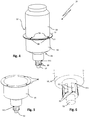
- FIG. 4 shows the packaging 12 in a perspective view.
- the flanges 22 of the first and second packaging part 16, 18 abut against each other.
- the packaging parts are detachably connected to one another by a click-on connection 56.
- the flange 30 of one of the packaging part is provided with impressions or holes 58.
- tongues or pins 60 provided on the flange 30 of the respective other packaging part 16, 18 which correspond to the impressions or holes and which, in the closed state of the click-on connection 56, engage therein.
- a ring shoulder not further shown in the figures and which engages in a circular groove of the respective other packaging part 16, 18.
- FIGS. 5 and 6 there is shown a perspective view of the funnel 26 of the first packaging part 16, wherein Fig. 6 is a detailed view of Fig. 5 showing the area around the plug 32 in greater detail.
- the lateral second orifices 30 of the funnel 26 are each provided with a flap 62.
- the flaps 62 primarily serve to slow down the fluid exiting via the second orifices to thus prevent spilling of the fluid 50.
- the packaging 12 comprises first packaging part 16 formed as a funnel 26, a second packaging part 18 in form of a carton and a third packaging part 46 which forms a stand for the fluid filter element 14.
- the first and the second packaging parts 16, 18 cooperate to form the receiving chamber 40 for the fluid filter element 14.
- the packaging 12 is preferably adapted to size of the fluid filter element 14 such that this is snugly seated in the second packaging part 18 for transport and storage.
- the first packaging part 16 serves to stabilize the filter element 14 inside the second packaging part 18 and further provides an impact protection for the fluid filter element 14.
- the first packaging part 16 preferably is made of plastics, whereas the second packaging part 18 can be made of e.g. cardboard, plastics or the like.
- the funnel 26 formed by the first packaging part 16 is pre-installed on the fluid filter element 14 ready for use.
- As the funnel 26 is already inserted into the clean side outlet 42 of the filter element 14 filling of the filter element 14 with e.g. residual fluid 50 from a second filter element 48 which is to be replaced by the first filter element 14 can commence right away, as is shown in FIG. 8 .
- the funnel 26 of the first packaging part 16 forms a plug 32 plugged into the clean side fluid outlet and thus protecting the clean side of the fluid filter element 14 against contamination with dirt, fluid and the like.
- the funnel 26 may have air ducts 66 which may be designed as radial grooves on the outer surface of the funnel 26 and which are shown in detail in FIGS. 10 and 11 .
- the air ducts 66 allow air to exit the fluid filter element 14 during prefilling thereof.
- FIG. 12 shows a block diagram of a method 100 for replacing a used fluid filter element 48 by a new (unused) first fluid filter element 14 ( Fig. 3 ) provided in a packaging 12 ( Fig. 1 ) according to the invention.
- the packaging 12 is designed as shown in Fig. 1
- the fluid filter element 14 is at least partially unpacked in a first step 102.
- the fluid filter element 14 is positioned on the stand 34 in its upright position A.
- the funnel 26 is connected to the raw side fluid inlet (of the fluid filter element 14 for filling the fluid filter element 14 with residual fluid contained in the second fluid filter element 48 which is to be replaced by the first filter element 14.
- the funnel 26 is, preferably, partially inserted into the clean side fluid outlet 42 of the fluid filter element with its plug.
- step 108 residual fluid 50 from the second fluid filter 48 element is introduced, that is decanted, into the first fluid filter element 14 for prefilling thereof via the funnel 26. If the filter elements 14, 48 are of identical design and size, the amount of residual fluid 50 cannot exceed the filling capacity of the first filter element 14. Spilling of residual fluid 50 can thereby be safely prevented.
- the said second fluid filter element 50 can be taken from the stand 34 and fitted in its dedicated mounting position, e.g. to a combustion engine of a car, a utility vehicle or a motor cycle.
- step 110 the first and the second packaging part 16, 18 are put together, enclosing the used (and now virtually emptied) fluid filter element 48 and cooperating together to form the receiving chamber 40 now receiving the used fluid filter element 48 for further transport and/or disposal thereof.
- the funnel is 26 connected prior to the at least partial unpacking step 102.
- the packaging 12 helps to avoid spilling of e.g. residual fuel and other ecological damage in two ways: Firstly, most of the residual fluid such as fuel or oil stemming from the second fluid filter element 48 can be easily transferred into the replacement fluid filter element 14 for reuse. Secondly, an unwanted contamination of the workplace and/or of a maintenance by the residual fuel can be avoided, thus making the filter element replacement cleaner and more comfortable. Thirdly, the packaging 12 can counteract a leakage of residual fluid 50 still remaining in the used second filter element which needs to be disposed during transport thereof.
Landscapes
- Engineering & Computer Science (AREA)
- Mechanical Engineering (AREA)
- Chemical & Material Sciences (AREA)
- Composite Materials (AREA)
- Packages (AREA)
- Filtration Of Liquid (AREA)
Abstract
Description
- The invention relates to a packaging for a fluid filter element, preferably of the type employed in filtering oil or fuel for an automotive or motorcycle engine, comprising at least a first packaging part and a second packaging part, wherein the first packaging part and the second packaging part can cooperate to define a receiving chamber for receiving therein a fluid filter element. The invention further relates to a packaging arrangement comprising such a packaging.
- Fluid filter elements are subject to wear and generally need to be replaced at certain maintenance intervals. New and unused fluid filter elements used for replacement are usually provided in so-called blister packs and/or cardboard boxes. A particular problem during replacement of a fluid filter element arises from the fact that the used fluid filter element that is to be replaced usually contains residual fluid, e.g. residual oil or fuel. Often, the said residual fluid is decanted into the replacement fluid filter element during replacement of the filter element. This, however, often leads to an unwanted spilling of the fluid and contamination of the surrounding. Further, the used fluid filter element as well as the residual fluid contained therein should be disposed properly to reduce environmental risks associated therewith.
- A packaging for the transport and storage of a fluid filter element is disclosed, for instance, in
WO 92/18397 - A further packaging for a fluid filter element is known from
US 3,710,930 . The packaging provides a support shell. The support shell can be employed as a hand-tool in removing a spent fluid filter element from a heated engine. - The object of the invention is to provide an improved packaging and packaging arrangement for a fluid filter element. A further object of the invention is to provide an improved method for replacing a, preferably used, fluid filter element by an unused fluid filter element provided in an aforementioned packaging. The object of the invention concerning the packaging is solved by a packaging according to
claim 1. A packaging arrangement according to the invention is given inclaim 10. The method for replacement of a fluid filter element is given in claim 13. Preferred embodiments of the invention are given in the dependent claims and the description. - According to the invention, the packaging for a fluid filter element, preferably of the type employed in filtering oil or fuel, in particular of an automotive or motorcycle engine, comprises at least a first packaging part and a second packaging part. The first packaging part and the second packaging part can be adapted to cooperate to define a receiving chamber for receiving therein the fluid filter element. The packaging, preferably the first packaging part, comprises a funnel for filling the fluid filter element with fluid. The funnel preferably has a first orifice serving as funnel inlet and one or more second orifices serving as funnel outlets. When replacing a used filter element, it is possible to connect the funnel to an inlet of the new (unused) fluid filter element for decanting residual fluid, in particular oil or fuel (e.g. gasoline/diesel), contained in the used fluid filter element into the new fluid filter element. The funnel further has a connecting pipe section on which the second orifice serving as a funnel outlet is present. The connecting pipe section is adapted to be sealingly connected with an inlet of said filter element, so that none of the fluid that is being fed through the funnel is spilled. This can be done in a clean and easy fashion without spilling of fluid or the need for a specific tooling equipment. Even if the residual fluid transferred from the used filter element contains contaminants such as particulate matter, the absolute quantity of residual fluid usually is sufficiently small such that no significant adverse effects to the new fluid filter element or other parts to be supplied with filtered fluid, e.g. a combustion engine, are to be expected. This is, in particular, the case when the residual fluid is introduced into the dirty side of the filter element, that is the side of the unfiltered fluid upstream a respective filter medium of the fluid filter element. The packaging according to the invention thus serves both as a protective cover for the new fluid filter element during transport or storage and as a, preferably single-use, maintenance tool for replacing the used fluid filter element with the new fluid filter element. Moreover, the packaging according to the invention helps protect the environment as residual fluid is not dispensed into the environment but can be kept safely within the new fluid filter element until the new fluid filter element is put to use.
- If the first packaging part forms the funnel the manufacturing of the funnel does not require any additional, costly manufacturing steps in addition to the manufacturing, e.g. injection-molding, of the first packaging part.
- According to a further embodiment of the invention the packaging, preferably the second packaging part, comprises or forms a stand for positioning and holding the fluid filter element in an upright position or an essentially upright position. An "upright position" is understood to mean a position of the fluid filter element in which fluid can be poured into the fluid filter element through an inlet of the fluid filter element. "Bottom" and "bottom side" refer to the lower part, respectively, the bottom side of the fluid filter element being positioned in its upright position. Analogously, "top" and "top side" refer to the upper part, respectively, the top side of the fluid filter element being positioned in its upright position. Most off-the-shelf fluid filter elements cannot remain in an upright position when placed on a surface, e.g. a table top or the ground. This is because their bottom is usually not flat, but e.g. rounded and/or has projections at the bottom thereof. The stand allows to reliably position and hold the filter element in an upright position as needed for filling (the residual) fluid into the filter element.
- The stand may be at least partially formed ring-shaped, in particular cylindrically or conically. The cross-sectional shape of the stand can be circular for instance. By this, the filter element may be simply inserted into the central opening of the stand to position the filter element in the upright or essentially upright position.
- Fluid filter elements available on the market often have their raw side fluid inlet surrounding their centrally located clean side fluid outlet. According to a preferred embodiment of the invention, the packaging, in particular the funnel, may, therefore, comprise a plug for sealing off a clean side outlet of the fluid filter element during filling thereof. The plug preferably is present on or at the connecting pipe section of the funnel; in particular it can be formed as a closed axial end or wall of the same. The plug is preferably directly molded onto or formed by the funnel, e.g. an outlet spigot thereof. Thereby, the plug can be automatically inserted/plugged into the clean side outlet of the fluid filter which needs to be filled, as soon as the funnel is placed onto the fluid filter element's inlet. The funnel, in particular an outlet spigot of the funnel, in this case, preferably has lateral openings and a blind end. Thereby, the residual fluid may be introduced into the raw side of the filter element while the fluid filter element's clean side is protected from potentially contaminated residual fluid of the filter element which needs to be replaced.
- The second packaging part may have a bowl-shaped or an essentially bowl-shaped form. Thus, the fluid filter element can be inserted into the second packaging part for transport and/or storage. The bowl-shaped second packaging part, according to the invention, can be designed as a self-supporting structure which can stand in an upright position by itself.
- According to the invention, the second packaging part may be designed and adapted to support the fluid filter element in an upright position for decanting residual fluid from another filter element therein. The second packaging part, in other words, may be designed as a support or stand for the fluid filter element. For this, the second packaging part may have a plane end for positioning the second packaging part on a suitable surface, e.g. a table top or the ground. In this case, the second packaging part also has a double function. Thereby, unnecessary additional manufacturing steps or costs incurred when providing a separate stand for the fluid filter element are avoided.
- According to the invention, the first and the second packaging part preferably form a blister packaging for the filter element. For this, the first and second packaging parts each may have a ring shoulder or flange which project in a radial direction, preferably outwards, from the respective packaging part and which abut against each other when the blister packaging is closed.
- The first packaging part and/or the second packaging part may have at least one fastening means by which the first packaging part and the second packaging part may be detachably fastened to one another. When a filter element is positioned inside the blister packaging, it may thereby be protected against coarse contaminants. Preferably, there is provided a click-on connection or a tongue-and-groove joint formed by the first and second packaging part, in particular in the region of the aforementioned flanges.
- For a higher degree of protection of the filter element against smaller contaminants or leaking fluids, the packaging may have additional sealing means by which the receiving chamber may be sealed off against the outside. Thus, a fluid filter element placed inside the receiving chamber may be protected hermetically against contamination. Moreover, if the fluid filter element is filled with a fluid, e. g. a residual fluid, the fluid cannot leak out of the receiving chamber. The sealing means may comprise a sealing ring of rubber or elastomeric material which is arranged, in particular molded onto, one of the flanges of the first or second packaging part.
- The first packaging part and/or the second packaging part may be made of a plastic material, in particular a thermoplastic such as, for instance, polypropylene, polyethylene or polymethylpentene. Moreover, the first and/or the second packaging part may be stiff and/or bending-resistant and may have a thickness between 0.2 and 2 mm.
- In another embodiment the first packaging part and/or the second packaging part can be made of paper and/or cardboard or a combination thereof. The paper and/or cardboard can also be impregnated in order to achieve a greater resistance to the fluid to be filled into the filter element, e.g. fuel, in particular diesel fuel. Furthermore, other materials that have a similar resistance to said fluids can be used to form the first packaging part and/or the second packaging part, e.g. metals. In this case, there is preferably provided an additional stand for positioning and holding the fluid filter element in its upright position as needed for filling a fluid therein.
- The packaging arrangement, according to the invention, comprises a packaging according to the invention and a fluid filter element wherein the fluid filter element is received in the receiving chamber of the packaging. The funnel is installed on the fluid filter element, preferably partially inserted into, e.g. an inlet, of the fluid filter element. In particular, in such a packaging arrangement the funnel may be pre-installed, for example by a manufacturer of the packaging arrangement, on the fluid filter element. The inlet may preferably be the raw side inlet of the fluid filter element. Thus, without unpacking or at least without fully unpacking the fluid filter element from the packaging, it is possible to pour e.g. residual fluid through the funnel into the fluid filter element. A further improvement is achieved by also installing, preferably pre-installing, the stand, preferably on the bottom of the packed fluid filter element. The fluid filter element may, in particular, be a fuel or oil filter element.
- The aforementioned funnel may comprise or form at least one air exit allowing air to exit the fluid filter element while fluid is poured thereinto. The air exit may comprise one or more grooves formed on the funnel.
- According to a further preferred embodiment of the invention, the funnel may be connected to a raw side inlet of the fluid filter element. The funnel's outlet may open in a direction perpendicular or essentially perpendicular to the longitudinal axis of the fluid filter element. In this case, the funnel is provided with one or more radial or lateral orifices to thereby allow a fluid flow directly to the raw side inlet of a filter element.
- The method for replacing a first, preferably used, fluid filter element by a second, preferably unused, fluid filter element provided in a packaging according to the invention comprises the following steps:
- connecting the funnel to, preferably partially inserting said funnel into, a raw side fluid inlet of said unused fluid filter element for filling said unused fluid filter element with residual fluid contained in the used fluid filter element; and
- decanting the residual fluid of the used fluid filter element through said funnel into said unused fluid filter element.
- The residual fluid contained in the filter element which needs to be replaced can thus be introduced into the unused fluid filter element without any additional tool, e.g. a separate funnel, which needs to be provided and cleaned after use. The first fluid filter element may be emptied and the residual fluid may be disposed in a very easy, clean, and ecofriendly way. The funnel is preferably pre-installed, particularly by a manufacturer of the fluid filter element and/or the packaging, on the second fluid filter element. Thus, in order to empty the first fluid filter element, the second fluid filter element does not need to be unpacked from the packaging. Alternatively, the fluid filter element can be unpacked from the packaging before connecting the funnel to the inlet of the second fluid filter element.
- According to a further embodiment of the invention, the method further comprises the step of using the second packaging part of the packaging or another packaging part as a stand for positioning and holding the unused fluid filter element in an upright position. Moreover, the stand for holding the second fluid filter element in an upright position, may be pre-installed at the bottom of the second fluid filter element. In this way, the second fluid filter element may already be safely positioned within e.g. a cardboard box or carton, in particular for transportation purposes.
- Various other features and attendant advantages of the present invention will be more fully appreciated as the same becomes better understood when considered in conjunction with the accompanying drawings, and wherein:
- Fig. 1
- shows a cross-sectional view of a packaging arrangement with a packaging comprising a first packaging part which forms a funnel, a second packaging part which serves as a stand and a fluid filter element positioned inside the packaging for transport and storage thereof;
- Fig. 2
- shows use of the packaging arrangement according to
Fig. 1 for positioning the fluid filter element in an upright position by use of the stand and with the funnel coupled to and partially inserted into the fluid filter element; - Fig. 3
- shows a detailed section of the packaging arrangement according to
Fig. 2 with the fluid filter element and the funnel connected thereto when pouring residual fluid from a used further filter element into the new/unused fluid filter element; - Figs. 4 to 6
- show perspective views of a first packaging part and a second packaging part of the packaging arrangement according to
Fig. 1 in assembled (Fig. 4 ) and disassembled conditions (Fig. 5 and 6 ); - Fig. 7
- shows a further embodiment of a packaging arrangement wherein the first packaging part is formed as a funnel which is preinstalled on the fluid filter element for filling fluid therein and wherein the second packaging part is formed as a carton, the fluid filter element engaging in a separate stand provided in the carton, in a sectional view;
- Fig. 8
- shows a partial view of the packaging arrangement according to
Fig. 7 when pouring residual fluid from a used fluid filter element into the first filter element provided inside the carton and positioned in an upright position; - Fig. 9
- shows the stand of the packaging arrangement according to
Fig. 7 in a perspective view; - Figs. 10 and 11
- show the funnel of the packaging arrangement according to
Fig. 7 in different views; - Fig. 12
- shows a block diagram with different steps of a method for replacing a used fluid filter element with a new fluid filter element provided in a packaging according to
Figs 1 or7 . -
FIG. 1 shows apackaging arrangement 10 comprising apackaging 12 and a firstfluid filter element 14 contained therein. Thepackaging 12 serves as protective cover of the firstfluid filter element 14 during transport and storage. Thepackaging 10 has a two-part design and comprises afirst packaging part 16 and asecond packaging part 18. The first and thesecond packaging parts chamber 20 for thefluid filter element 14. The first and second packaging parts both may have a, preferably ring-shaped,flange 22 which projects in a radial direction from therespective packaging part longitudinal axis 24 of thepackage arrangement 10 orpackaging 12, respectively. Theflanges 22 abut against each other and serve for an attachment of the twopackaging parts - The
first packaging part 16 forms afunnel 26. Thefunnel 26 has a first (inlet)orifice 28, several second lateral (outlet) orifices 30 and aplug 32 as shall be explained in further detail below. Thesecond orifices 30 are present on a connecting pipe section of thefunnel 26 that is axially extending and formed in one piece with thefunnel 26. The connectingpipe section 300 is dimensioned so as to fit properly sealingly into oninlet 40 of thefilter element 14. Alternatively the connectingpipe section 300 can be adapted to be sealingly connected to an outlet of thefilter element 14; this actually depends on the internal structure of thefilter element 14. The connectingpipe section 300 can of course haveless openings 30, e.g. only one and is embodied as a fluidic socket or fitting. - The
second packaging part 18 is generally bowl-shaped. It comprises a cylindrical end section which forms astand 34. Thestand 34 may have aflat face 36 which is perpendicularly arranged in relation to thelongitudinal axis 24 of thepackage arrangement 10. - The
fluid filter element 14 has atop end 38 with a rawside fluid inlet 40 and a central cleanside fluid outlet 42. The cleanside fluid outlet 42 is embraced by the raw side fluid inlet. The rawside fluid inlet 40 may comprise several inlet holes which are arranged circular around thelongitudinal axis 24 of thefluid filter element 14. On abottom end 44 of thefilter element 14 there is a water outlet or water drainage W provided. Thefluid filter element 14 is shown in its upright position A. Thepackaging arrangement 10 may comprise afurther packaging element 46 in the form of a carton, in particular a folding carton in which thepackaging 12 and thefilter element 14 are contained. - The first and
second packaging parts FIGS. 2 and3 . When a usedfluid filter element 48, which is preferably identical in design to the firstfluid filter element 14, needs to be replaced, theresidual fluid 50 which is usually contained therein, may be used for prefilling of the firstfluid filter element 14. For this, the firstfluid filter element 14 is removed from thepackaging 12. Thesecond packaging part 18 is arranged on asurface 52 such as the ground, a table top or the like with itsstand 34 facing down. The firstfluid filter element 14 which is to be prefilled with fluid is introduced into thesecond packaging 18 with itsbottom end 44 facing down. The firstfluid filter element 14 is thus held in an upright position by thesecond packaging part 18 which serves as a standing aid for thefilter element 18. Thefirst packaging part 16, with its funnel, is arranged at thetop end 38 of the firstfluid filter element 14. Theplug 32 of thefunnel 26 sealingly engages in the cleanside fluid outlet 42 of the firstfluid filter element 14. Theoutlet 42 and thus the clean side of the firstfluid filter element 14 is thus protected against an ingress of fluid via thefunnel 26. Theresidual fluid 50 can be poured via the funnel and thesecond orifices 30 thereof into the firstfluid filter element 14 without the need for holding on to it. -
FIG. 3 shows a detailed view of thefirst packaging part 16 when coupled to thefirst filter element 14 for prefilling. Thefunnel 26 is partially introduced into thetop end 38 of the firstfluid filter element 14. Arrows 54 depict the flow path of theresidual fluid 50 from the second fluid filter element.Plug 32 fully plugs theclean side outlet 52 thus deflecting the flow path 70 of the fluid 50 towards thesecond orifices 30 of thefilter element 14. Thesecond orifices 30 open in a radial direction to further direct the flow of the fluid 50 right to the rawside fluid inlet 40 of thefluid filter element 14. -
FIG. 4 shows thepackaging 12 in a perspective view. Theflanges 22 of the first andsecond packaging part connection 56. To this end, theflange 30 of one of the packaging part is provided with impressions or holes 58. There are tongues or pins 60 provided on theflange 30 of the respectiveother packaging part connection 56, engage therein. For an improved sealing of the twopackaging parts other packaging part packaging 12. - Referring to
FIGS. 5 and 6 , there is shown a perspective view of thefunnel 26 of thefirst packaging part 16, whereinFig. 6 is a detailed view ofFig. 5 showing the area around theplug 32 in greater detail. The lateralsecond orifices 30 of thefunnel 26 are each provided with aflap 62. Theflaps 62 primarily serve to slow down the fluid exiting via the second orifices to thus prevent spilling of the fluid 50. - A
further packaging arrangement 10 is shown inFIG. 7 . Thepackaging 12 comprisesfirst packaging part 16 formed as afunnel 26, asecond packaging part 18 in form of a carton and athird packaging part 46 which forms a stand for thefluid filter element 14. The first and thesecond packaging parts chamber 40 for thefluid filter element 14. Thepackaging 12 is preferably adapted to size of thefluid filter element 14 such that this is snugly seated in thesecond packaging part 18 for transport and storage. Thefirst packaging part 16 serves to stabilize thefilter element 14 inside thesecond packaging part 18 and further provides an impact protection for thefluid filter element 14. Thefirst packaging part 16 preferably is made of plastics, whereas thesecond packaging part 18 can be made of e.g. cardboard, plastics or the like. Thefunnel 26 formed by thefirst packaging part 16 is pre-installed on thefluid filter element 14 ready for use. Thefluid filter element 14, with itsbottom end 44, engages in the stand which has a cylindrical design as shown in detail inFIG. 9 . For prefilling of thefluid filter element 14, it is not necessary to fully unpack or remove thefluid filter element 14 from thepackaging 12. Simple opening or tearing off of atop flap 64 of thesecond packaging part 18 suffices. As thefunnel 26 is already inserted into theclean side outlet 42 of thefilter element 14 filling of thefilter element 14 with e.g. residual fluid 50 from asecond filter element 48 which is to be replaced by thefirst filter element 14 can commence right away, as is shown inFIG. 8 . Thefunnel 26 of thefirst packaging part 16 forms aplug 32 plugged into the clean side fluid outlet and thus protecting the clean side of thefluid filter element 14 against contamination with dirt, fluid and the like. Thefunnel 26 may haveair ducts 66 which may be designed as radial grooves on the outer surface of thefunnel 26 and which are shown in detail inFIGS. 10 and 11 . Theair ducts 66 allow air to exit thefluid filter element 14 during prefilling thereof. -
FIG. 12 shows a block diagram of amethod 100 for replacing a usedfluid filter element 48 by a new (unused) first fluid filter element 14 (Fig. 3 ) provided in a packaging 12 (Fig. 1 ) according to the invention. If thepackaging 12 is designed as shown inFig. 1 , thefluid filter element 14 is at least partially unpacked in afirst step 102. Instep 104, thefluid filter element 14 is positioned on thestand 34 in its upright position A. Instep 106, thefunnel 26 is connected to the raw side fluid inlet (of thefluid filter element 14 for filling thefluid filter element 14 with residual fluid contained in the secondfluid filter element 48 which is to be replaced by thefirst filter element 14. For this, thefunnel 26 is, preferably, partially inserted into the cleanside fluid outlet 42 of the fluid filter element with its plug. Instep 108,residual fluid 50 from thesecond fluid filter 48 element is introduced, that is decanted, into the firstfluid filter element 14 for prefilling thereof via thefunnel 26. If thefilter elements residual fluid 50 cannot exceed the filling capacity of thefirst filter element 14. Spilling ofresidual fluid 50 can thereby be safely prevented. As soon as the secondfluid filter element 48 is emptied, the said secondfluid filter element 50 can be taken from thestand 34 and fitted in its dedicated mounting position, e.g. to a combustion engine of a car, a utility vehicle or a motor cycle. Subsequently, inoptional step 110 the first and thesecond packaging part fluid filter element 48 and cooperating together to form the receivingchamber 40 now receiving the usedfluid filter element 48 for further transport and/or disposal thereof. In case that the packaging/packaging arrangement Fig. 7 , the funnel is 26 connected prior to the at leastpartial unpacking step 102. - Overall, the
packaging 12 helps to avoid spilling of e.g. residual fuel and other ecological damage in two ways: Firstly, most of the residual fluid such as fuel or oil stemming from the secondfluid filter element 48 can be easily transferred into the replacementfluid filter element 14 for reuse. Secondly, an unwanted contamination of the workplace and/or of a maintenance by the residual fuel can be avoided, thus making the filter element replacement cleaner and more comfortable. Thirdly, thepackaging 12 can counteract a leakage ofresidual fluid 50 still remaining in the used second filter element which needs to be disposed during transport thereof.
Claims (15)
- A packaging (12) for a fluid filter element (14), preferably of the type employed in filtering oil or fuel, in particular for an automotive engine, comprising at least a first packaging part (16) and a second packaging part (18), wherein said first packaging part (16) and said second packaging part (18) can be adapted to cooperate to define a receiving chamber (20) for receiving therein said fluid filter element (14), wherein the packaging (12), preferably the first packaging part (16), forms a funnel (26) for filling said fluid filter element (14) with fluid; the funnel (26) having a first orifice serving as a funnel inlet and at least one second orifice serving as a funnel outlet, wherein the second orifice is present at a connecting pipe section (300) of the funnel (26), that is adapted to be sealingly connected with an inlet (40) of said filter element (14).
- The packaging according to claim 1, characterized in that said packaging (12), preferably said second packaging part (18), comprises or forms a stand (34) for positioning and holding said fluid filter element (14) in an upright position or an essentially upright position, preferably by supporting the bottom end (44) of said fluid filter element (14).
- The packaging according to any one of the preceding claims, characterized in that said stand (34) is at least partially formed ring-shaped, in particular at least partly cylindrically or conically and/or has a circular cross-sectional shape.
- The packaging according to any one of the preceding claims, characterized in that said packaging (12), in particular said funnel (26), comprises a plug (32) for sealing a clean side outlet (42) of said fluid filter element (14).
- The packaging according to claim 4, characterized in that said plug (32) is present at the connecting pipe section (300) of said funnel (26).
- The packaging according to any one of the preceding claims, characterized in that said first packaging part (16) and/or said second packaging part (18) have at least one flange (22) for, in particular sealingly, connecting said first packaging part (16) and said second packaging part (18) to each other.
- The packaging according to any one of the preceding claims, characterized in that the second packaging part (18) has a bowl-shaped or an essentially bowl-shaped form.
- The packaging according to any one of the preceding claims, characterized in that said first packaging part (16) and said second packaging part (18) form a blister-packaging.
- The packaging according to any one the preceding claims, characterized in that the first packaging part (16) and/or the second packaging part (18) are made of plastics, in particular polypropylene and/or polyethylene and/or polymethylpentene, or paper and/or cardboard, preferably impregnated paper and/or cardboard.
- A packaging arrangement (10) comprising a packaging (12) according to any one of the preceding claims 1 to 9 and a fluid filter element (14) wherein said fluid filter element (14) is received in the receiving chamber (20) of the packaging (12), characterized in that said funnel (26) is installed on said fluid filter element (14), preferably partially inserted into an inlet (40) of the fluid filter element (14).
- The packaging arrangement (10) according to claim 10, characterized in that said funnel (26) is fluidly connected to a raw side fluid inlet (40) of said fluid filter element (14).
- The packaging arrangement according claim 10 or 11, characterized in that said funnel (26) comprises or forms at least one air exit (66) allowing air to exit said fluid filter element (14) while fluid is poured therein.
- A method for replacing a used fluid filter element (48) by an unused fluid filter element (14) provided in a packaging (12) according to any one of the preceding claims 1 to 9 comprising the following steps:- connecting (106) the funnel (26) to, preferably partially inserting said funnel (26) into, a raw side fluid inlet (40) of said unused fluid filter element (14) for filling said unused fluid filter element (14) with residual fluid contained in the used fluid filter element (48); and- decanting (108) the residual fluid of the used fluid filter element (48) through said funnel (26) into said unused fluid filter element (14).
- The method according to claim 13, further comprising the step of at least partially unpacking (102) said unused fluid filter element (14) from said packaging (12) before connecting said funnel (26) to said fluid inlet (26) of said unused fluid filter element (14).
- The method according to any one of the claims 13 or 14, further comprising the step of using (104) the second packaging part (18) of said packaging (12) as a stand (34) for positioning and holding said unused fluid filter element (14) in an upright position.
Applications Claiming Priority (1)
| Application Number | Priority Date | Filing Date | Title |
|---|---|---|---|
| EP17173198 | 2017-05-29 |
Publications (2)
| Publication Number | Publication Date |
|---|---|
| EP3409617A1 true EP3409617A1 (en) | 2018-12-05 |
| EP3409617B1 EP3409617B1 (en) | 2020-02-12 |
Family
ID=59054968
Family Applications (1)
| Application Number | Title | Priority Date | Filing Date |
|---|---|---|---|
| EP18174539.9A Active EP3409617B1 (en) | 2017-05-29 | 2018-05-28 | Packaging for a fluid filter element, packaging arrangement |
Country Status (1)
| Country | Link |
|---|---|
| EP (1) | EP3409617B1 (en) |
Citations (2)
| Publication number | Priority date | Publication date | Assignee | Title |
|---|---|---|---|---|
| US3710930A (en) * | 1970-12-21 | 1973-01-16 | M Owdom | Filter package |
| WO1992018397A1 (en) * | 1991-04-09 | 1992-10-29 | Hydac Filtertechnik Gmbh | Re-usable packing container for filter elements |
-
2018
- 2018-05-28 EP EP18174539.9A patent/EP3409617B1/en active Active
Patent Citations (2)
| Publication number | Priority date | Publication date | Assignee | Title |
|---|---|---|---|---|
| US3710930A (en) * | 1970-12-21 | 1973-01-16 | M Owdom | Filter package |
| WO1992018397A1 (en) * | 1991-04-09 | 1992-10-29 | Hydac Filtertechnik Gmbh | Re-usable packing container for filter elements |
Also Published As
| Publication number | Publication date |
|---|---|
| EP3409617B1 (en) | 2020-02-12 |
Similar Documents
| Publication | Publication Date | Title |
|---|---|---|
| CN102223940B (en) | Intake air filter for internal combustion engines | |
| EP2621601B1 (en) | Fluid filter system | |
| US5064458A (en) | Heavy duty air filter with multipurpose end seal | |
| US6739319B2 (en) | Fuel supply device of an internal combustion engine with a fuel filter | |
| US9289710B2 (en) | Filter element and air filter | |
| CN102348873B (en) | Oil tank | |
| CN101508377B (en) | Transport and storage container for liquids | |
| US9669972B2 (en) | Anti-glug device for liquid containers and pour spouts | |
| US10668410B2 (en) | Fuel filter comprising a fuel filter insert with a prefilter element and a main filter element | |
| AU2008326806A1 (en) | Fluid filter system | |
| JPH05261211A (en) | Fuel filter assembly | |
| US9908669B2 (en) | Anti-glug device for liquid containers and pour spouts | |
| CN101384325B (en) | Collapsible protective cover for a filter | |
| EP3409617B1 (en) | Packaging for a fluid filter element, packaging arrangement | |
| CN102686839A (en) | oil filter unit | |
| US4754896A (en) | Disposable leak proof filter container | |
| CN109108376A (en) | Oil tank for hand-held power tools and hand-held power tools with oil tank | |
| JP2005104591A (en) | Plastic removal device for liquid transport and storage containers | |
| EP2118470B1 (en) | Multi-use container for engine maintenance kit | |
| US20100170211A1 (en) | Intake Air Cleaner | |
| US4574972A (en) | Protective cap for diesel fuel filter | |
| CN110621412B (en) | Paint container with optimized closed member | |
| CN206315535U (en) | Filter for fluid feed system | |
| EP0583149B1 (en) | Disposal plug for filter cartridge | |
| CN112789222B (en) | Fluid filter package |
Legal Events
| Date | Code | Title | Description |
|---|---|---|---|
| PUAI | Public reference made under article 153(3) epc to a published international application that has entered the european phase |
Free format text: ORIGINAL CODE: 0009012 |
|
| STAA | Information on the status of an ep patent application or granted ep patent |
Free format text: STATUS: THE APPLICATION HAS BEEN PUBLISHED |
|
| AK | Designated contracting states |
Kind code of ref document: A1 Designated state(s): AL AT BE BG CH CY CZ DE DK EE ES FI FR GB GR HR HU IE IS IT LI LT LU LV MC MK MT NL NO PL PT RO RS SE SI SK SM TR |
|
| AX | Request for extension of the european patent |
Extension state: BA ME |
|
| RIN1 | Information on inventor provided before grant (corrected) |
Inventor name: KLEIN, MARTIN Inventor name: KUMAR RAJAGOPAL, MADHU |
|
| STAA | Information on the status of an ep patent application or granted ep patent |
Free format text: STATUS: REQUEST FOR EXAMINATION WAS MADE |
|
| 17P | Request for examination filed |
Effective date: 20190516 |
|
| RBV | Designated contracting states (corrected) |
Designated state(s): AL AT BE BG CH CY CZ DE DK EE ES FI FR GB GR HR HU IE IS IT LI LT LU LV MC MK MT NL NO PL PT RO RS SE SI SK SM TR |
|
| RIC1 | Information provided on ipc code assigned before grant |
Ipc: B65D 81/36 20060101AFI20190626BHEP Ipc: B65D 75/32 20060101ALI20190626BHEP Ipc: B65D 85/68 20060101ALI20190626BHEP |
|
| GRAP | Despatch of communication of intention to grant a patent |
Free format text: ORIGINAL CODE: EPIDOSNIGR1 |
|
| STAA | Information on the status of an ep patent application or granted ep patent |
Free format text: STATUS: GRANT OF PATENT IS INTENDED |
|
| INTG | Intention to grant announced |
Effective date: 20190819 |
|
| GRAS | Grant fee paid |
Free format text: ORIGINAL CODE: EPIDOSNIGR3 |
|
| GRAA | (expected) grant |
Free format text: ORIGINAL CODE: 0009210 |
|
| STAA | Information on the status of an ep patent application or granted ep patent |
Free format text: STATUS: THE PATENT HAS BEEN GRANTED |
|
| AK | Designated contracting states |
Kind code of ref document: B1 Designated state(s): AL AT BE BG CH CY CZ DE DK EE ES FI FR GB GR HR HU IE IS IT LI LT LU LV MC MK MT NL NO PL PT RO RS SE SI SK SM TR |
|
| REG | Reference to a national code |
Ref country code: GB Ref legal event code: FG4D |
|
| REG | Reference to a national code |
Ref country code: CH Ref legal event code: EP |
|
| REG | Reference to a national code |
Ref country code: AT Ref legal event code: REF Ref document number: 1231810 Country of ref document: AT Kind code of ref document: T Effective date: 20200215 |
|
| REG | Reference to a national code |
Ref country code: IE Ref legal event code: FG4D |
|
| REG | Reference to a national code |
Ref country code: DE Ref legal event code: R096 Ref document number: 602018002363 Country of ref document: DE |
|
| PG25 | Lapsed in a contracting state [announced via postgrant information from national office to epo] |
Ref country code: FI Free format text: LAPSE BECAUSE OF FAILURE TO SUBMIT A TRANSLATION OF THE DESCRIPTION OR TO PAY THE FEE WITHIN THE PRESCRIBED TIME-LIMIT Effective date: 20200212 Ref country code: NO Free format text: LAPSE BECAUSE OF FAILURE TO SUBMIT A TRANSLATION OF THE DESCRIPTION OR TO PAY THE FEE WITHIN THE PRESCRIBED TIME-LIMIT Effective date: 20200512 Ref country code: RS Free format text: LAPSE BECAUSE OF FAILURE TO SUBMIT A TRANSLATION OF THE DESCRIPTION OR TO PAY THE FEE WITHIN THE PRESCRIBED TIME-LIMIT Effective date: 20200212 |
|
| REG | Reference to a national code |
Ref country code: LT Ref legal event code: MG4D |
|
| REG | Reference to a national code |
Ref country code: NL Ref legal event code: MP Effective date: 20200212 |
|
| PG25 | Lapsed in a contracting state [announced via postgrant information from national office to epo] |
Ref country code: IS Free format text: LAPSE BECAUSE OF FAILURE TO SUBMIT A TRANSLATION OF THE DESCRIPTION OR TO PAY THE FEE WITHIN THE PRESCRIBED TIME-LIMIT Effective date: 20200612 Ref country code: BG Free format text: LAPSE BECAUSE OF FAILURE TO SUBMIT A TRANSLATION OF THE DESCRIPTION OR TO PAY THE FEE WITHIN THE PRESCRIBED TIME-LIMIT Effective date: 20200512 Ref country code: GR Free format text: LAPSE BECAUSE OF FAILURE TO SUBMIT A TRANSLATION OF THE DESCRIPTION OR TO PAY THE FEE WITHIN THE PRESCRIBED TIME-LIMIT Effective date: 20200513 Ref country code: LV Free format text: LAPSE BECAUSE OF FAILURE TO SUBMIT A TRANSLATION OF THE DESCRIPTION OR TO PAY THE FEE WITHIN THE PRESCRIBED TIME-LIMIT Effective date: 20200212 Ref country code: SE Free format text: LAPSE BECAUSE OF FAILURE TO SUBMIT A TRANSLATION OF THE DESCRIPTION OR TO PAY THE FEE WITHIN THE PRESCRIBED TIME-LIMIT Effective date: 20200212 Ref country code: HR Free format text: LAPSE BECAUSE OF FAILURE TO SUBMIT A TRANSLATION OF THE DESCRIPTION OR TO PAY THE FEE WITHIN THE PRESCRIBED TIME-LIMIT Effective date: 20200212 |
|
| PG25 | Lapsed in a contracting state [announced via postgrant information from national office to epo] |
Ref country code: NL Free format text: LAPSE BECAUSE OF FAILURE TO SUBMIT A TRANSLATION OF THE DESCRIPTION OR TO PAY THE FEE WITHIN THE PRESCRIBED TIME-LIMIT Effective date: 20200212 |
|
| PG25 | Lapsed in a contracting state [announced via postgrant information from national office to epo] |
Ref country code: PT Free format text: LAPSE BECAUSE OF FAILURE TO SUBMIT A TRANSLATION OF THE DESCRIPTION OR TO PAY THE FEE WITHIN THE PRESCRIBED TIME-LIMIT Effective date: 20200705 Ref country code: LT Free format text: LAPSE BECAUSE OF FAILURE TO SUBMIT A TRANSLATION OF THE DESCRIPTION OR TO PAY THE FEE WITHIN THE PRESCRIBED TIME-LIMIT Effective date: 20200212 Ref country code: ES Free format text: LAPSE BECAUSE OF FAILURE TO SUBMIT A TRANSLATION OF THE DESCRIPTION OR TO PAY THE FEE WITHIN THE PRESCRIBED TIME-LIMIT Effective date: 20200212 Ref country code: RO Free format text: LAPSE BECAUSE OF FAILURE TO SUBMIT A TRANSLATION OF THE DESCRIPTION OR TO PAY THE FEE WITHIN THE PRESCRIBED TIME-LIMIT Effective date: 20200212 Ref country code: CZ Free format text: LAPSE BECAUSE OF FAILURE TO SUBMIT A TRANSLATION OF THE DESCRIPTION OR TO PAY THE FEE WITHIN THE PRESCRIBED TIME-LIMIT Effective date: 20200212 Ref country code: SK Free format text: LAPSE BECAUSE OF FAILURE TO SUBMIT A TRANSLATION OF THE DESCRIPTION OR TO PAY THE FEE WITHIN THE PRESCRIBED TIME-LIMIT Effective date: 20200212 Ref country code: SM Free format text: LAPSE BECAUSE OF FAILURE TO SUBMIT A TRANSLATION OF THE DESCRIPTION OR TO PAY THE FEE WITHIN THE PRESCRIBED TIME-LIMIT Effective date: 20200212 Ref country code: EE Free format text: LAPSE BECAUSE OF FAILURE TO SUBMIT A TRANSLATION OF THE DESCRIPTION OR TO PAY THE FEE WITHIN THE PRESCRIBED TIME-LIMIT Effective date: 20200212 Ref country code: DK Free format text: LAPSE BECAUSE OF FAILURE TO SUBMIT A TRANSLATION OF THE DESCRIPTION OR TO PAY THE FEE WITHIN THE PRESCRIBED TIME-LIMIT Effective date: 20200212 |
|
| REG | Reference to a national code |
Ref country code: DE Ref legal event code: R097 Ref document number: 602018002363 Country of ref document: DE |
|
| REG | Reference to a national code |
Ref country code: AT Ref legal event code: MK05 Ref document number: 1231810 Country of ref document: AT Kind code of ref document: T Effective date: 20200212 |
|
| PLBE | No opposition filed within time limit |
Free format text: ORIGINAL CODE: 0009261 |
|
| STAA | Information on the status of an ep patent application or granted ep patent |
Free format text: STATUS: NO OPPOSITION FILED WITHIN TIME LIMIT |
|
| 26N | No opposition filed |
Effective date: 20201113 |
|
| PG25 | Lapsed in a contracting state [announced via postgrant information from national office to epo] |
Ref country code: IT Free format text: LAPSE BECAUSE OF FAILURE TO SUBMIT A TRANSLATION OF THE DESCRIPTION OR TO PAY THE FEE WITHIN THE PRESCRIBED TIME-LIMIT Effective date: 20200212 Ref country code: MC Free format text: LAPSE BECAUSE OF FAILURE TO SUBMIT A TRANSLATION OF THE DESCRIPTION OR TO PAY THE FEE WITHIN THE PRESCRIBED TIME-LIMIT Effective date: 20200212 Ref country code: AT Free format text: LAPSE BECAUSE OF FAILURE TO SUBMIT A TRANSLATION OF THE DESCRIPTION OR TO PAY THE FEE WITHIN THE PRESCRIBED TIME-LIMIT Effective date: 20200212 |
|
| PG25 | Lapsed in a contracting state [announced via postgrant information from national office to epo] |
Ref country code: SI Free format text: LAPSE BECAUSE OF FAILURE TO SUBMIT A TRANSLATION OF THE DESCRIPTION OR TO PAY THE FEE WITHIN THE PRESCRIBED TIME-LIMIT Effective date: 20200212 Ref country code: PL Free format text: LAPSE BECAUSE OF FAILURE TO SUBMIT A TRANSLATION OF THE DESCRIPTION OR TO PAY THE FEE WITHIN THE PRESCRIBED TIME-LIMIT Effective date: 20200212 |
|
| REG | Reference to a national code |
Ref country code: BE Ref legal event code: MM Effective date: 20200531 |
|
| PG25 | Lapsed in a contracting state [announced via postgrant information from national office to epo] |
Ref country code: LU Free format text: LAPSE BECAUSE OF NON-PAYMENT OF DUE FEES Effective date: 20200528 |
|
| PG25 | Lapsed in a contracting state [announced via postgrant information from national office to epo] |
Ref country code: IE Free format text: LAPSE BECAUSE OF NON-PAYMENT OF DUE FEES Effective date: 20200528 Ref country code: FR Free format text: LAPSE BECAUSE OF NON-PAYMENT OF DUE FEES Effective date: 20200531 |
|
| PG25 | Lapsed in a contracting state [announced via postgrant information from national office to epo] |
Ref country code: BE Free format text: LAPSE BECAUSE OF NON-PAYMENT OF DUE FEES Effective date: 20200531 |
|
| REG | Reference to a national code |
Ref country code: CH Ref legal event code: PL |
|
| PG25 | Lapsed in a contracting state [announced via postgrant information from national office to epo] |
Ref country code: LI Free format text: LAPSE BECAUSE OF NON-PAYMENT OF DUE FEES Effective date: 20210531 Ref country code: CH Free format text: LAPSE BECAUSE OF NON-PAYMENT OF DUE FEES Effective date: 20210531 |
|
| PG25 | Lapsed in a contracting state [announced via postgrant information from national office to epo] |
Ref country code: TR Free format text: LAPSE BECAUSE OF FAILURE TO SUBMIT A TRANSLATION OF THE DESCRIPTION OR TO PAY THE FEE WITHIN THE PRESCRIBED TIME-LIMIT Effective date: 20200212 Ref country code: MT Free format text: LAPSE BECAUSE OF FAILURE TO SUBMIT A TRANSLATION OF THE DESCRIPTION OR TO PAY THE FEE WITHIN THE PRESCRIBED TIME-LIMIT Effective date: 20200212 Ref country code: CY Free format text: LAPSE BECAUSE OF FAILURE TO SUBMIT A TRANSLATION OF THE DESCRIPTION OR TO PAY THE FEE WITHIN THE PRESCRIBED TIME-LIMIT Effective date: 20200212 |
|
| PG25 | Lapsed in a contracting state [announced via postgrant information from national office to epo] |
Ref country code: MK Free format text: LAPSE BECAUSE OF FAILURE TO SUBMIT A TRANSLATION OF THE DESCRIPTION OR TO PAY THE FEE WITHIN THE PRESCRIBED TIME-LIMIT Effective date: 20200212 Ref country code: AL Free format text: LAPSE BECAUSE OF FAILURE TO SUBMIT A TRANSLATION OF THE DESCRIPTION OR TO PAY THE FEE WITHIN THE PRESCRIBED TIME-LIMIT Effective date: 20200212 |
|
| GBPC | Gb: european patent ceased through non-payment of renewal fee |
Effective date: 20220528 |
|
| PG25 | Lapsed in a contracting state [announced via postgrant information from national office to epo] |
Ref country code: GB Free format text: LAPSE BECAUSE OF NON-PAYMENT OF DUE FEES Effective date: 20220528 |
|
| PGFP | Annual fee paid to national office [announced via postgrant information from national office to epo] |
Ref country code: DE Payment date: 20260522 Year of fee payment: 9 |