EP3409590A1 - Aircraft with a bleed air heating system for apu compartment - Google Patents
Aircraft with a bleed air heating system for apu compartment Download PDFInfo
- Publication number
- EP3409590A1 EP3409590A1 EP17382329.5A EP17382329A EP3409590A1 EP 3409590 A1 EP3409590 A1 EP 3409590A1 EP 17382329 A EP17382329 A EP 17382329A EP 3409590 A1 EP3409590 A1 EP 3409590A1
- Authority
- EP
- European Patent Office
- Prior art keywords
- apu
- bleed air
- temperature
- air
- compartment
- Prior art date
- Legal status (The legal status is an assumption and is not a legal conclusion. Google has not performed a legal analysis and makes no representation as to the accuracy of the status listed.)
- Granted
Links
Images
Classifications
-
- B—PERFORMING OPERATIONS; TRANSPORTING
- B64—AIRCRAFT; AVIATION; COSMONAUTICS
- B64D—EQUIPMENT FOR FITTING IN OR TO AIRCRAFT; FLIGHT SUITS; PARACHUTES; ARRANGEMENT OR MOUNTING OF POWER PLANTS OR PROPULSION TRANSMISSIONS IN AIRCRAFT
- B64D41/00—Power installations for auxiliary purposes
-
- B—PERFORMING OPERATIONS; TRANSPORTING
- B64—AIRCRAFT; AVIATION; COSMONAUTICS
- B64D—EQUIPMENT FOR FITTING IN OR TO AIRCRAFT; FLIGHT SUITS; PARACHUTES; ARRANGEMENT OR MOUNTING OF POWER PLANTS OR PROPULSION TRANSMISSIONS IN AIRCRAFT
- B64D13/00—Arrangements or adaptations of air-treatment apparatus for aircraft crew or passengers, or freight space
- B64D13/06—Arrangements or adaptations of air-treatment apparatus for aircraft crew or passengers, or freight space the air being conditioned
- B64D13/08—Arrangements or adaptations of air-treatment apparatus for aircraft crew or passengers, or freight space the air being conditioned the air being heated or cooled
-
- B—PERFORMING OPERATIONS; TRANSPORTING
- B64—AIRCRAFT; AVIATION; COSMONAUTICS
- B64D—EQUIPMENT FOR FITTING IN OR TO AIRCRAFT; FLIGHT SUITS; PARACHUTES; ARRANGEMENT OR MOUNTING OF POWER PLANTS OR PROPULSION TRANSMISSIONS IN AIRCRAFT
- B64D13/00—Arrangements or adaptations of air-treatment apparatus for aircraft crew or passengers, or freight space
- B64D13/06—Arrangements or adaptations of air-treatment apparatus for aircraft crew or passengers, or freight space the air being conditioned
- B64D2013/0603—Environmental Control Systems
- B64D2013/0611—Environmental Control Systems combined with auxiliary power units (APU's)
-
- B—PERFORMING OPERATIONS; TRANSPORTING
- B64—AIRCRAFT; AVIATION; COSMONAUTICS
- B64D—EQUIPMENT FOR FITTING IN OR TO AIRCRAFT; FLIGHT SUITS; PARACHUTES; ARRANGEMENT OR MOUNTING OF POWER PLANTS OR PROPULSION TRANSMISSIONS IN AIRCRAFT
- B64D13/00—Arrangements or adaptations of air-treatment apparatus for aircraft crew or passengers, or freight space
- B64D13/06—Arrangements or adaptations of air-treatment apparatus for aircraft crew or passengers, or freight space the air being conditioned
- B64D2013/0603—Environmental Control Systems
- B64D2013/0618—Environmental Control Systems with arrangements for reducing or managing bleed air, using another air source, e.g. ram air
Definitions
- the present invention refers to a bleed air heating system for an auxiliary power unit (APU) compartment of an aircraft, in order to de-ice the fuel trapped in the APU before starting and after being disconnected for a long time under freezing conditions.
- APU auxiliary power unit
- An object of the invention is to provide an aircraft with a bleed air heating system that is capable of defrosting the fuel contained in the APU, to offer a quick startup and operation of the APU when necessary.
- Another object of the present invention is to provide an aircraft with a bleed air heating system that maximizes commonality and reuses of pneumatic system components in existing aircrafts.
- the auxiliary power unit is a gas turbine engine that traditionally supplies electric and pneumatic power to the aircraft systems as an auxiliary or secondary source of power.
- the APU allows the aircraft to be autonomous of external electric and pneumatic power sources on ground and in-flight.
- This electric and pneumatic power can be provided to the aircraft separately or in combination.
- the pneumatic power provides compressed air for the cabin and power for main engines starting.
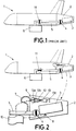
- Figure 1 shows a conventional APU bleed supply architecture.
- the architecture comprises an APU (3) hold in the APU compartment (2) provided in the tail cone of the aircraft (1), an APU bleed valve (4) configured to open and close the bleed air passage from the APU (3), and an APU bleed air duct (5) for conveying the APU bleed air towards the main engines (6).
- Some bleed supply architectures further comprise an isolation valve (11) to protect the APU (3) when no compressed air is being supplied.
- the aircraft's fuel system may provide fuel with a high concentration of liquid water. Once the APU is stopped, this mixture of fuel and water gets trapped inside all the fuel system cavities, conducts, valves, pumps, actuators, sensors, etc.
- APU gets exposed to water subfreezing temperatures during long periods of time, such as when aircraft is parked overnight or during cruise flight, where APU shuts off once the main engines get started.
- the present invention overcomes the above mentioned drawbacks by providing an aircraft with a bleed air heating system for the APU compartment that heats the overall APU compartment, to defrost the mixture of fuel and water trapped in the APU. Additionally, the invention provides a simple solution that maximizes the reuse of conventional components of the APU bleed air supply.
- the invention refers to an aircraft comprising a main engine capable of providing bleed air supply, an auxiliary power unit housed within an APU compartment and having an APU bleed valve configured to control the bleed air passage into the auxiliary power unit, an APU bleed air duct connecting the main engine with the auxiliary power unit to provide a bleed air passage, and a bleed air heating system for the APU compartment, which comprises an auxiliary pipeline, an auxiliary pipeline valve, a temperature sensor, and a temperature controller.
- the auxiliary pipeline is tapped to the APU bleed air duct and connected to the APU compartment. This way, the bleed air carried by the APU bleed air duct can be discharged into the APU compartment.
- the auxiliary pipeline valve is configured to control the bleed air discharged from the auxiliary pipeline into the APU compartment. This way, the system can regulate the amount of bleed air discharged into the APU compartment.
- the temperature sensor is placed to sense the temperature of the APU compartment. This way, the bleed air heating system allows continuous monitoring of the temperature in the APU compartment, and quickly acts when required.
- the temperature controller is coupled to the temperature sensor to receive the sensed the temperature, and is adapted to establish a heating operation mode or a standby operation mode depending on the sensed temperature.
- the heating operation mode is established when the sensed temperature falls below a minimum temperature threshold value
- the standby operation mode is established when the sensed temperature surpasses a maximum temperature threshold value.
- the temperature controller is adapted to command the closing of the APU bleed valve for avoiding the bleed air enter into the auxiliary power unit, activate the bleed air supply of the main engine, and activate the opening of the auxiliary pipeline valve for conducting bleed air from the main engine towards the APU compartment, to heat said APU compartment.
- the temperature controller is adapted to deactivate the bleed air supply of the main engine, activate the closing of the auxiliary pipeline valve to stop heating the APU compartment, and command the opening of the APU bleed valve to allow the bleed air enter into the auxiliary power unit.
- the temperature controller is thus adapted to operate the system in two modes of operation, the heating operation mode in which bleed air of the main engine is used for heating the overall APU compartment, and the standby operation mode in which bleed air is no longer required because the APU compartment is above the maximum temperature threshold value.
- the temperature controller allows maintaining the temperature of the APU compartment within a safety margin.
- the invention thus provides a safe defrost without risk of overheating of the APU or even fire.
- the bleed air heating system is integrated in conventional pneumatic architectures, reusing components, and offering a more efficient architecture.
- the invention thus improves the aircraft performance by enabling a quick start of the APU when it has to be restarted after being shut down under water subfreezing temperatures. This start is mainly required when the aircraft is parked, and also before landing, when APU is required to feed the systems and provide cabin conditioned air during disembarkation.
- Figure 2 shows a schematic and detailed view of an aircraft 1 that comprises at least one main engine 6 adapted to provide bleed air supply and preferentially installed at the central section of the aircraft 1, and an APU 3 housed within an APU compartment 2 installed at the tail cone of the aircraft 1.
- An APU bleed air duct 5 is disposed to connect the main engine 6 with the APU 3 for providing bleed air passage.
- the APU bleed air duct 5 is traditionally used for conducting APU bleed air to the main engines.
- the invention contemplates the use of this duct 5 for carrying the air in reverse flow, that is, from the main engine 6 towards the APU 3 when the APU compartment 2 needs to be heated.
- the APU 3 has an APU bleed valve 4 configured to selectively routed the bleed air to the main engine 6 or back to the APU 3.
- the aircraft further comprises a bleed air heating system for the APU compartment 2.
- This system comprises an auxiliary pipeline 7, an auxiliary pipeline valve 9, a temperature sensor 8, and a temperature controller 10 adapt to operate the main engine 6 and both valves 4, 9 to activate and deactivate the heating of the APU compartment 2.
- the auxiliary pipeline 7 is connected between the APU bleed air duct 5 and the APU compartment 2, to allow bleed air to enter the APU compartment 2.
- the auxiliary pipeline valve 9 is configured to selectively open and close the discharge of bleed air into the APU compartment 2.
- the temperature sensor 8 is placed within the APU compartment 2 to sense the temperature of said compartment 2.
- the temperature controller 10 is coupled with the temperature sensor 8, the main engine 6, the APU bleed valve 4 and the auxiliary pipeline valve 9 to perform safe heating the APU compartment.
- the temperature controller 10 is adapted to receive the sensed temperature, and establish a heating operation mode if the sensed temperature falls below a minimum temperature threshold value, and a standby mode if the sensed temperature surpasses a maximum temperature threshold value and the APU compartment does not need to be heated.
- the temperature controller is adapted to command the closing of the APU bleed valve to avoid the bleed air enter into the APU, activate the bleed air supply of the main engine, and activate the opening of the auxiliary pipeline valve to conduct bleed air from the main engine towards the APU compartment, and heat it.
- the temperature controller is adapted to deactivate the bleed air supply of the main engine, activate the closing of the auxiliary pipeline valve to stop heating the APU compartment, and command the opening of the APU bleed valve to allow the bleed air enter into the APU.
- the maximum established temperature threshold is about 4°C.
- the bleed air heating system may further comprise at least one electrically controlled injection nozzle 12 for injecting the bleed air conducted by the auxiliary pipeline 7 into the APU compartment 2, and wherein the temperature controller 10 is electrically coupled with the injection nozzle 12 and is further adapted to regulate the air flow injection rate of the nozzle 12 to maintain the temperature in the APU compartment 2 within the minimum and maximum threshold values.
- the nozzle provides a better control over the bleed air discharged, and thus a more reliable and safe heating.
- the bleed air heating system further comprises an air mixer 13 having a first passage 13a to receive the bleed air exiting the auxiliary pipeline 7, a second passage 13b to receive the air contained in the APU compartment 2, and an outlet 13c to drain the mixed air into the APU compartment 2.
- the air mixer helps to mix the bleed air with the APU compartment air. This provides a more uniform heating of the APU compartment, and also helps the sensor to provide more reliable measures.
- the air mixer 13 further comprises a jet pump positioned downstream of the air mixer outlet for receiving and impulsing the mixed air into the APU compartment 2. This pump helps reaching all areas of the APU compartment.
- the air mixer 13 is adapted for pumping mixed air at constant speed. This way, the APU compartment is uniformly heated, reducing the risk of overheating the APU.
- the temperature controller 10 is electrically coupled with the air mixer 13, and is further adapted to regulate the temperature of the pumped air (mixed of bleed air and APU compartment air). This provides a safer heating, in addition to reducing the risk of overheating of the APU.
- the temperature of the pumped air is regulated so that it does not exceed 200°C.
- the auxiliary pipeline valve 9 is pneumatically activated by a spring.
- the auxiliary pipeline valve 9 is a pneumatic valve, which is spring loaded towards a closed position, for safety reasons, and that when is electrically commanded it goes to open position as driven by an electric solenoid.
- the aircraft 1 further comprises an isolation valve 11, and the temperature controller 10 is coupled to said isolation valve 11 and further adapted to command the opening of said isolation valve 11, to allow the bleed air to be conducted from the main engine 6 towards the APU 3, when the sensed temperature falls below a minimum temperature threshold value. Further, the temperature controller 10 is adapted to command the closing of the isolation valve 11, to avoid bleed air being driven from the main engine 6 towards the APU 3 when the sensed temperature surpasses a maximum temperature threshold value.
- the aircraft 1 further comprises an APU compartment fire protection system, wherein the temperature controller 10 is coupled with said APU compartment fire protection system to establish the maximum temperature threshold value.
- the temperature controller 10 is coupled with said APU compartment fire protection system to establish the maximum temperature threshold value.
Landscapes
- Engineering & Computer Science (AREA)
- Aviation & Aerospace Engineering (AREA)
- Health & Medical Sciences (AREA)
- General Health & Medical Sciences (AREA)
- Pulmonology (AREA)
- Air-Conditioning For Vehicles (AREA)
- Supplying Secondary Fuel Or The Like To Fuel, Air Or Fuel-Air Mixtures (AREA)
Abstract
Description
- The present invention refers to a bleed air heating system for an auxiliary power unit (APU) compartment of an aircraft, in order to de-ice the fuel trapped in the APU before starting and after being disconnected for a long time under freezing conditions.
- An object of the invention is to provide an aircraft with a bleed air heating system that is capable of defrosting the fuel contained in the APU, to offer a quick startup and operation of the APU when necessary.
- Another object of the present invention is to provide an aircraft with a bleed air heating system that maximizes commonality and reuses of pneumatic system components in existing aircrafts.
- The auxiliary power unit (APU) is a gas turbine engine that traditionally supplies electric and pneumatic power to the aircraft systems as an auxiliary or secondary source of power. The APU allows the aircraft to be autonomous of external electric and pneumatic power sources on ground and in-flight.
- This electric and pneumatic power can be provided to the aircraft separately or in combination. The pneumatic power provides compressed air for the cabin and power for main engines starting.
-
Figure 1 shows a conventional APU bleed supply architecture. As shown, the architecture comprises an APU (3) hold in the APU compartment (2) provided in the tail cone of the aircraft (1), an APU bleed valve (4) configured to open and close the bleed air passage from the APU (3), and an APU bleed air duct (5) for conveying the APU bleed air towards the main engines (6). - Some bleed supply architectures further comprise an isolation valve (11) to protect the APU (3) when no compressed air is being supplied.
- Under certain conditions, the aircraft's fuel system may provide fuel with a high concentration of liquid water. Once the APU is stopped, this mixture of fuel and water gets trapped inside all the fuel system cavities, conducts, valves, pumps, actuators, sensors, etc.
- It is also frequent, that the APU gets exposed to water subfreezing temperatures during long periods of time, such as when aircraft is parked overnight or during cruise flight, where APU shuts off once the main engines get started.
- In these cases, lumps of liquid water get solidified and cause internal fuel systems blockages that impede the start and the normal running process of the APU.
- It would therefore be desirable to provide technical means to an aircraft for defrosting the fuel trapped in the APU, to thus improve the starting and operation phases of the APU irrespective of the freezing conditions.
- The present invention overcomes the above mentioned drawbacks by providing an aircraft with a bleed air heating system for the APU compartment that heats the overall APU compartment, to defrost the mixture of fuel and water trapped in the APU. Additionally, the invention provides a simple solution that maximizes the reuse of conventional components of the APU bleed air supply.
- The invention refers to an aircraft comprising a main engine capable of providing bleed air supply, an auxiliary power unit housed within an APU compartment and having an APU bleed valve configured to control the bleed air passage into the auxiliary power unit, an APU bleed air duct connecting the main engine with the auxiliary power unit to provide a bleed air passage, and a bleed air heating system for the APU compartment, which comprises an auxiliary pipeline, an auxiliary pipeline valve, a temperature sensor, and a temperature controller.
- The auxiliary pipeline is tapped to the APU bleed air duct and connected to the APU compartment. This way, the bleed air carried by the APU bleed air duct can be discharged into the APU compartment.
- The auxiliary pipeline valve is configured to control the bleed air discharged from the auxiliary pipeline into the APU compartment. This way, the system can regulate the amount of bleed air discharged into the APU compartment.
- The temperature sensor is placed to sense the temperature of the APU compartment. This way, the bleed air heating system allows continuous monitoring of the temperature in the APU compartment, and quickly acts when required.
- The temperature controller is coupled to the temperature sensor to receive the sensed the temperature, and is adapted to establish a heating operation mode or a standby operation mode depending on the sensed temperature. The heating operation mode is established when the sensed temperature falls below a minimum temperature threshold value, and the standby operation mode is established when the sensed temperature surpasses a maximum temperature threshold value.
- When the heating operation mode is established, the temperature controller is adapted to command the closing of the APU bleed valve for avoiding the bleed air enter into the auxiliary power unit, activate the bleed air supply of the main engine, and activate the opening of the auxiliary pipeline valve for conducting bleed air from the main engine towards the APU compartment, to heat said APU compartment.
- When the standby operation mode is established, the temperature controller is adapted to deactivate the bleed air supply of the main engine, activate the closing of the auxiliary pipeline valve to stop heating the APU compartment, and command the opening of the APU bleed valve to allow the bleed air enter into the auxiliary power unit.
- The temperature controller is thus adapted to operate the system in two modes of operation, the heating operation mode in which bleed air of the main engine is used for heating the overall APU compartment, and the standby operation mode in which bleed air is no longer required because the APU compartment is above the maximum temperature threshold value.
- The temperature controller allows maintaining the temperature of the APU compartment within a safety margin. The invention thus provides a safe defrost without risk of overheating of the APU or even fire.
- The bleed air heating system is integrated in conventional pneumatic architectures, reusing components, and offering a more efficient architecture.
- The invention thus improves the aircraft performance by enabling a quick start of the APU when it has to be restarted after being shut down under water subfreezing temperatures. This start is mainly required when the aircraft is parked, and also before landing, when APU is required to feed the systems and provide cabin conditioned air during disembarkation.
- For a better comprehension of the invention, the following drawings are provided for illustrative and non-limiting purposes, wherein:
-
Figure 1 shows a schematic view of an aircraft with a conventional pneumatic system, in which the APU provides bleed air supply. -
Figure 2 shows a schematic and detailed view of an aircraft equipped with a bleed air heating system, according to an embodiment of the present invention. -
Figure 2 shows a schematic and detailed view of an aircraft 1 that comprises at least onemain engine 6 adapted to provide bleed air supply and preferentially installed at the central section of the aircraft 1, and an APU 3 housed within anAPU compartment 2 installed at the tail cone of the aircraft 1. - An APU bleed
air duct 5 is disposed to connect themain engine 6 with theAPU 3 for providing bleed air passage. The APU bleedair duct 5 is traditionally used for conducting APU bleed air to the main engines. However, the invention contemplates the use of thisduct 5 for carrying the air in reverse flow, that is, from themain engine 6 towards theAPU 3 when theAPU compartment 2 needs to be heated. - The APU 3 has an APU bleed valve 4 configured to selectively routed the bleed air to the
main engine 6 or back to theAPU 3. - According to the invention, the aircraft further comprises a bleed air heating system for the
APU compartment 2. This system comprises an auxiliary pipeline 7, anauxiliary pipeline valve 9, atemperature sensor 8, and atemperature controller 10 adapt to operate themain engine 6 and bothvalves 4, 9 to activate and deactivate the heating of theAPU compartment 2. - The auxiliary pipeline 7 is connected between the APU bleed
air duct 5 and theAPU compartment 2, to allow bleed air to enter theAPU compartment 2. - The
auxiliary pipeline valve 9 is configured to selectively open and close the discharge of bleed air into theAPU compartment 2. - The
temperature sensor 8 is placed within theAPU compartment 2 to sense the temperature of saidcompartment 2. - The
temperature controller 10 is coupled with thetemperature sensor 8, themain engine 6, the APU bleed valve 4 and theauxiliary pipeline valve 9 to perform safe heating the APU compartment. - The
temperature controller 10 is adapted to receive the sensed temperature, and establish a heating operation mode if the sensed temperature falls below a minimum temperature threshold value, and a standby mode if the sensed temperature surpasses a maximum temperature threshold value and the APU compartment does not need to be heated. - On heating operation mode, the temperature controller is adapted to command the closing of the APU bleed valve to avoid the bleed air enter into the APU, activate the bleed air supply of the main engine, and activate the opening of the auxiliary pipeline valve to conduct bleed air from the main engine towards the APU compartment, and heat it.
- On standby operation mode, the temperature controller is adapted to deactivate the bleed air supply of the main engine, activate the closing of the auxiliary pipeline valve to stop heating the APU compartment, and command the opening of the APU bleed valve to allow the bleed air enter into the APU.
- Preferably, the maximum established temperature threshold is about 4°C.
- As shown in
Figure 2 , the bleed air heating system may further comprise at least one electrically controlledinjection nozzle 12 for injecting the bleed air conducted by the auxiliary pipeline 7 into theAPU compartment 2, and wherein thetemperature controller 10 is electrically coupled with theinjection nozzle 12 and is further adapted to regulate the air flow injection rate of thenozzle 12 to maintain the temperature in theAPU compartment 2 within the minimum and maximum threshold values. The nozzle provides a better control over the bleed air discharged, and thus a more reliable and safe heating. - According to another preferred embodiment, the bleed air heating system further comprises an
air mixer 13 having afirst passage 13a to receive the bleed air exiting the auxiliary pipeline 7, asecond passage 13b to receive the air contained in theAPU compartment 2, and an outlet 13c to drain the mixed air into theAPU compartment 2. The air mixer helps to mix the bleed air with the APU compartment air. This provides a more uniform heating of the APU compartment, and also helps the sensor to provide more reliable measures. - Preferentially, the
air mixer 13 further comprises a jet pump positioned downstream of the air mixer outlet for receiving and impulsing the mixed air into theAPU compartment 2. This pump helps reaching all areas of the APU compartment. - Preferably, the
air mixer 13 is adapted for pumping mixed air at constant speed. This way, the APU compartment is uniformly heated, reducing the risk of overheating the APU. - Preferably, the
temperature controller 10 is electrically coupled with theair mixer 13, and is further adapted to regulate the temperature of the pumped air (mixed of bleed air and APU compartment air). This provides a safer heating, in addition to reducing the risk of overheating of the APU. Preferably, the temperature of the pumped air is regulated so that it does not exceed 200°C. - Preferably, the
auxiliary pipeline valve 9 is pneumatically activated by a spring. Preferably, theauxiliary pipeline valve 9 is a pneumatic valve, which is spring loaded towards a closed position, for safety reasons, and that when is electrically commanded it goes to open position as driven by an electric solenoid. - According to another preferred embodiment, the aircraft 1 further comprises an
isolation valve 11, and thetemperature controller 10 is coupled to saidisolation valve 11 and further adapted to command the opening of saidisolation valve 11, to allow the bleed air to be conducted from themain engine 6 towards theAPU 3, when the sensed temperature falls below a minimum temperature threshold value. Further, thetemperature controller 10 is adapted to command the closing of theisolation valve 11, to avoid bleed air being driven from themain engine 6 towards theAPU 3 when the sensed temperature surpasses a maximum temperature threshold value. - According to another preferred embodiment, the aircraft 1 further comprises an APU compartment fire protection system, wherein the
temperature controller 10 is coupled with said APU compartment fire protection system to establish the maximum temperature threshold value. Using information of the fire protection system offers a safe heating, without fire risks.
Claims (9)
- An aircraft (1) comprising:- a main engine (6) capable of providing bleed air supply,- an auxiliary power unit (3) housed within an APU compartment (2), and having an APU bleed valve (4) configured to control the bleed air passage into the auxiliary power unit (3),- an APU bleed air duct (5) connecting the main engine (6) with the auxiliary power unit (3) to provide a bleed air passage,characterized in that additionally comprises a bleed air heating system for the APU compartment (2) that comprises:- an auxiliary pipeline (7) tapped to the APU bleed air duct (5) and connected to the APU compartment (2),- an auxiliary pipeline valve (9) configured to control the bleed air discharged from the auxiliary pipeline (7) into the APU compartment (2),- a temperature sensor (8) placed to sense the temperature of the APU compartment (2), and- a temperature controller (10) coupled to the temperature sensor (8) to receive the sensed the temperature, and adapted to establish a heating operation mode when the sensed temperature falls below a minimum temperature threshold value, and a standby operation mode when the sensed temperature surpasses a maximum temperature threshold value,- wherein, when the heating operation mode is established, the temperature controller (10) is adapted to:- command the closing of the APU bleed valve (4) for avoiding the bleed air enter into the auxiliary power unit (3),- activate the bleed air supply of the main engine (6), and- activate the opening of the auxiliary pipeline valve (9) for conducting bleed air from the main engine (6) towards the APU compartment (2), to heat said APU compartment (2),- and wherein, when the standby operation mode is established, the temperature controller (10) is adapted to:- deactivate the bleed air supply of the main engine (6),- activate the closing of the auxiliary pipeline valve (9) to stop heating the APU compartment (2), and- command the opening of the APU bleed valve (4) to allow the bleed air enter into the auxiliary power unit (3).
- An aircraft, according to claim 1, wherein the bleed air heating system further comprises at least one electrically controlled injection nozzle (12) for injecting bleed air conducted by the auxiliary pipeline (7) into the APU compartment (2), and wherein the temperature controller (10) is electrically coupled with the injection nozzle (12) and is further adapted to regulate the air flow injection rate of the nozzle (12) to maintain the temperature in the APU compartment (2) within the minimum and maximum threshold values.
- An aircraft, according to claim 2, wherein the bleed air heating system further comprises an air mixer (13) having a first passage (13a) to receive the bleed air exiting the auxiliary pipeline (7), a second passage (13b) to receive the air contained in the APU compartment (2), and an outlet (13c) to drain the mixed air into the APU compartment (2).
- An aircraft, according to claim 3, wherein the air mixer (13) further comprises a jet pump positioned downstream of the air mixer outlet for receiving and impulsing the mixed air into the APU compartment (2).
- An aircraft, according to any of claims 3-4, wherein the air mixer (13) is adapted for pumping mixed air at constant speed.
- An aircraft, according to any of claims 3-5, wherein the temperature controller (10) is electrically coupled with the air mixer (13), and is further adapted to regulate the temperature of the pumped air.
- An aircraft, according to any preceding claims, wherein the auxiliary pipeline valve (9) is pneumatically activated by a spring.
- An aircraft, according to any preceding claims, further comprising an isolation valve (11), wherein the temperature controller (10) is coupled to said isolation valve (11) and is adapted to command the opening of said isolation valve (11) to allow bleed air to be conducted from the main engine (6) towards the APU (3) when the sensed temperature falls below a minimum temperature threshold value, and the closing of said isolation valve (11) to avoid bleed air being conducted from the main engine (6) towards the APU (3) when the sensed temperature surpasses a maximum temperature threshold value.
- An aircraft, according to any preceding claims, further comprising an APU compartment fire protection system, wherein the temperature controller (10) is coupled with said APU compartment fire protection system to establish the maximum temperature threshold value.
Priority Applications (3)
| Application Number | Priority Date | Filing Date | Title |
|---|---|---|---|
| ES17382329T ES2777823T3 (en) | 2017-06-02 | 2017-06-02 | Aircraft with a purge air heating system for APU compartment |
| EP17382329.5A EP3409590B1 (en) | 2017-06-02 | 2017-06-02 | Aircraft with a bleed air heating system for apu compartment |
| US15/995,439 US10752366B2 (en) | 2017-06-02 | 2018-06-01 | Aircraft with a bleed air heating system for APU compartment |
Applications Claiming Priority (1)
| Application Number | Priority Date | Filing Date | Title |
|---|---|---|---|
| EP17382329.5A EP3409590B1 (en) | 2017-06-02 | 2017-06-02 | Aircraft with a bleed air heating system for apu compartment |
Publications (2)
| Publication Number | Publication Date |
|---|---|
| EP3409590A1 true EP3409590A1 (en) | 2018-12-05 |
| EP3409590B1 EP3409590B1 (en) | 2020-01-01 |
Family
ID=59077999
Family Applications (1)
| Application Number | Title | Priority Date | Filing Date |
|---|---|---|---|
| EP17382329.5A Active EP3409590B1 (en) | 2017-06-02 | 2017-06-02 | Aircraft with a bleed air heating system for apu compartment |
Country Status (3)
| Country | Link |
|---|---|
| US (1) | US10752366B2 (en) |
| EP (1) | EP3409590B1 (en) |
| ES (1) | ES2777823T3 (en) |
Families Citing this family (1)
| Publication number | Priority date | Publication date | Assignee | Title |
|---|---|---|---|---|
| US12129037B2 (en) | 2021-11-11 | 2024-10-29 | Textron Innovations Inc. | Heating control system and method for unpressurized aircraft |
Citations (2)
| Publication number | Priority date | Publication date | Assignee | Title |
|---|---|---|---|---|
| FR3013683A1 (en) * | 2013-11-27 | 2015-05-29 | Microturbo | METHOD AND SYSTEM FOR OPTIMIZED PRODUCTION OF NON-PROPULSIVE ENERGY |
| EP3127814A1 (en) * | 2015-08-07 | 2017-02-08 | Pratt & Whitney Canada Corp. | Aircraft heating assembly with liquid cooled internal combustion engine and heating element using waste heat |
Family Cites Families (3)
| Publication number | Priority date | Publication date | Assignee | Title |
|---|---|---|---|---|
| US9205927B2 (en) * | 2013-04-10 | 2015-12-08 | Honeywell International Inc. | Aircraft environmental control system inlet flow control |
| US10011361B2 (en) * | 2015-11-16 | 2018-07-03 | Textron Innovations Inc. | Aircraft environmental control system providing improved performance and backup temperature control |
| US9789967B2 (en) * | 2015-12-16 | 2017-10-17 | Hamilton Sundstrand Corporation | Environmental control system |
-
2017
- 2017-06-02 ES ES17382329T patent/ES2777823T3/en active Active
- 2017-06-02 EP EP17382329.5A patent/EP3409590B1/en active Active
-
2018
- 2018-06-01 US US15/995,439 patent/US10752366B2/en active Active
Patent Citations (2)
| Publication number | Priority date | Publication date | Assignee | Title |
|---|---|---|---|---|
| FR3013683A1 (en) * | 2013-11-27 | 2015-05-29 | Microturbo | METHOD AND SYSTEM FOR OPTIMIZED PRODUCTION OF NON-PROPULSIVE ENERGY |
| EP3127814A1 (en) * | 2015-08-07 | 2017-02-08 | Pratt & Whitney Canada Corp. | Aircraft heating assembly with liquid cooled internal combustion engine and heating element using waste heat |
Also Published As
| Publication number | Publication date |
|---|---|
| EP3409590B1 (en) | 2020-01-01 |
| ES2777823T3 (en) | 2020-08-06 |
| US10752366B2 (en) | 2020-08-25 |
| US20180346131A1 (en) | 2018-12-06 |
Similar Documents
| Publication | Publication Date | Title |
|---|---|---|
| US8602362B2 (en) | System and method for scavenging ullage from center wing tanks in an airplane | |
| US10239623B2 (en) | Aircraft air conditioning system and method of operating an aircraft air conditioning system | |
| EP3473842B1 (en) | Electric cruise pump system | |
| US8444093B1 (en) | Airplane leading edge de-icing apparatus | |
| CN105438481B (en) | The method of aircraft air-conditioning system and operation aircraft air-conditioning system | |
| US10377498B2 (en) | Aircraft and associated method for providing electrical energy to an anti-icing system | |
| EP3242004B1 (en) | Systems and methods for preventing ice formation on portions of an aircraft | |
| US10604263B2 (en) | Mixing bleed and ram air using a dual use turbine system | |
| ES2947461T3 (en) | Aircraft installation for pressurized air supply | |
| EP3103719B1 (en) | Fuel tank inerting apparatus for aircraft | |
| EP3144224A1 (en) | Ram air channel arrangement and method for operating a ram air channel arrangement | |
| CN109312691B (en) | Device for spraying water in a vehicle and method for operating such a device | |
| EP3672872A1 (en) | Apparatus and methods for providing air to pneumatic loads onboard aircraft | |
| EP3409590B1 (en) | Aircraft with a bleed air heating system for apu compartment | |
| US11814180B2 (en) | Air management system for an aircraft | |
| HK1215293A1 (en) | Gas engine assembly | |
| US8899009B2 (en) | Fuel anti-icing and APU compartment drain combination | |
| US20120036866A1 (en) | Auxiliary power unit with multiple fuel sources | |
| US10094298B2 (en) | Ecology system ejector pump shutoff valve | |
| CN112173124B (en) | Air management system for an aircraft, method for supplying pressurized air and aircraft | |
| US20230391458A1 (en) | Module for supplying pressurized fresh air to an air-conditioning pack of an aircraft cabin, air-conditioning system equipped with such a module, and corresponding method | |
| US20180036565A1 (en) | Method and system for inerting a fuel tank | |
| KR101251638B1 (en) | Meteorological fuel supply | |
| RU2564436C1 (en) | Thermal protection of payload arranged in assembly-protective unit and device to this end | |
| US2424754A (en) | Fuel feeding system with combined valve and air vent |
Legal Events
| Date | Code | Title | Description |
|---|---|---|---|
| PUAI | Public reference made under article 153(3) epc to a published international application that has entered the european phase |
Free format text: ORIGINAL CODE: 0009012 |
|
| STAA | Information on the status of an ep patent application or granted ep patent |
Free format text: STATUS: THE APPLICATION HAS BEEN PUBLISHED |
|
| AK | Designated contracting states |
Kind code of ref document: A1 Designated state(s): AL AT BE BG CH CY CZ DE DK EE ES FI FR GB GR HR HU IE IS IT LI LT LU LV MC MK MT NL NO PL PT RO RS SE SI SK SM TR |
|
| AX | Request for extension of the european patent |
Extension state: BA ME |
|
| STAA | Information on the status of an ep patent application or granted ep patent |
Free format text: STATUS: REQUEST FOR EXAMINATION WAS MADE |
|
| 17P | Request for examination filed |
Effective date: 20190529 |
|
| RBV | Designated contracting states (corrected) |
Designated state(s): AL AT BE BG CH CY CZ DE DK EE ES FI FR GB GR HR HU IE IS IT LI LT LU LV MC MK MT NL NO PL PT RO RS SE SI SK SM TR |
|
| GRAP | Despatch of communication of intention to grant a patent |
Free format text: ORIGINAL CODE: EPIDOSNIGR1 |
|
| STAA | Information on the status of an ep patent application or granted ep patent |
Free format text: STATUS: GRANT OF PATENT IS INTENDED |
|
| RIC1 | Information provided on ipc code assigned before grant |
Ipc: B64D 41/00 20060101AFI20190917BHEP |
|
| INTG | Intention to grant announced |
Effective date: 20191022 |
|
| GRAS | Grant fee paid |
Free format text: ORIGINAL CODE: EPIDOSNIGR3 |
|
| GRAA | (expected) grant |
Free format text: ORIGINAL CODE: 0009210 |
|
| STAA | Information on the status of an ep patent application or granted ep patent |
Free format text: STATUS: THE PATENT HAS BEEN GRANTED |
|
| AK | Designated contracting states |
Kind code of ref document: B1 Designated state(s): AL AT BE BG CH CY CZ DE DK EE ES FI FR GB GR HR HU IE IS IT LI LT LU LV MC MK MT NL NO PL PT RO RS SE SI SK SM TR |
|
| REG | Reference to a national code |
Ref country code: GB Ref legal event code: FG4D |
|
| REG | Reference to a national code |
Ref country code: CH Ref legal event code: EP Ref country code: AT Ref legal event code: REF Ref document number: 1219508 Country of ref document: AT Kind code of ref document: T Effective date: 20200115 |
|
| REG | Reference to a national code |
Ref country code: IE Ref legal event code: FG4D |
|
| REG | Reference to a national code |
Ref country code: DE Ref legal event code: R096 Ref document number: 602017010376 Country of ref document: DE |
|
| REG | Reference to a national code |
Ref country code: NL Ref legal event code: MP Effective date: 20200101 |
|
| REG | Reference to a national code |
Ref country code: LT Ref legal event code: MG4D |
|
| PG25 | Lapsed in a contracting state [announced via postgrant information from national office to epo] |
Ref country code: LT Free format text: LAPSE BECAUSE OF FAILURE TO SUBMIT A TRANSLATION OF THE DESCRIPTION OR TO PAY THE FEE WITHIN THE PRESCRIBED TIME-LIMIT Effective date: 20200101 Ref country code: RS Free format text: LAPSE BECAUSE OF FAILURE TO SUBMIT A TRANSLATION OF THE DESCRIPTION OR TO PAY THE FEE WITHIN THE PRESCRIBED TIME-LIMIT Effective date: 20200101 Ref country code: FI Free format text: LAPSE BECAUSE OF FAILURE TO SUBMIT A TRANSLATION OF THE DESCRIPTION OR TO PAY THE FEE WITHIN THE PRESCRIBED TIME-LIMIT Effective date: 20200101 Ref country code: NO Free format text: LAPSE BECAUSE OF FAILURE TO SUBMIT A TRANSLATION OF THE DESCRIPTION OR TO PAY THE FEE WITHIN THE PRESCRIBED TIME-LIMIT Effective date: 20200401 Ref country code: NL Free format text: LAPSE BECAUSE OF FAILURE TO SUBMIT A TRANSLATION OF THE DESCRIPTION OR TO PAY THE FEE WITHIN THE PRESCRIBED TIME-LIMIT Effective date: 20200101 Ref country code: CZ Free format text: LAPSE BECAUSE OF FAILURE TO SUBMIT A TRANSLATION OF THE DESCRIPTION OR TO PAY THE FEE WITHIN THE PRESCRIBED TIME-LIMIT Effective date: 20200101 Ref country code: PT Free format text: LAPSE BECAUSE OF FAILURE TO SUBMIT A TRANSLATION OF THE DESCRIPTION OR TO PAY THE FEE WITHIN THE PRESCRIBED TIME-LIMIT Effective date: 20200527 |
|
| REG | Reference to a national code |
Ref country code: ES Ref legal event code: FG2A Ref document number: 2777823 Country of ref document: ES Kind code of ref document: T3 Effective date: 20200806 |
|
| PG25 | Lapsed in a contracting state [announced via postgrant information from national office to epo] |
Ref country code: HR Free format text: LAPSE BECAUSE OF FAILURE TO SUBMIT A TRANSLATION OF THE DESCRIPTION OR TO PAY THE FEE WITHIN THE PRESCRIBED TIME-LIMIT Effective date: 20200101 Ref country code: GR Free format text: LAPSE BECAUSE OF FAILURE TO SUBMIT A TRANSLATION OF THE DESCRIPTION OR TO PAY THE FEE WITHIN THE PRESCRIBED TIME-LIMIT Effective date: 20200402 Ref country code: LV Free format text: LAPSE BECAUSE OF FAILURE TO SUBMIT A TRANSLATION OF THE DESCRIPTION OR TO PAY THE FEE WITHIN THE PRESCRIBED TIME-LIMIT Effective date: 20200101 Ref country code: SE Free format text: LAPSE BECAUSE OF FAILURE TO SUBMIT A TRANSLATION OF THE DESCRIPTION OR TO PAY THE FEE WITHIN THE PRESCRIBED TIME-LIMIT Effective date: 20200101 Ref country code: IS Free format text: LAPSE BECAUSE OF FAILURE TO SUBMIT A TRANSLATION OF THE DESCRIPTION OR TO PAY THE FEE WITHIN THE PRESCRIBED TIME-LIMIT Effective date: 20200501 Ref country code: BG Free format text: LAPSE BECAUSE OF FAILURE TO SUBMIT A TRANSLATION OF THE DESCRIPTION OR TO PAY THE FEE WITHIN THE PRESCRIBED TIME-LIMIT Effective date: 20200401 |
|
| REG | Reference to a national code |
Ref country code: DE Ref legal event code: R097 Ref document number: 602017010376 Country of ref document: DE |
|
| PG25 | Lapsed in a contracting state [announced via postgrant information from national office to epo] |
Ref country code: RO Free format text: LAPSE BECAUSE OF FAILURE TO SUBMIT A TRANSLATION OF THE DESCRIPTION OR TO PAY THE FEE WITHIN THE PRESCRIBED TIME-LIMIT Effective date: 20200101 Ref country code: SK Free format text: LAPSE BECAUSE OF FAILURE TO SUBMIT A TRANSLATION OF THE DESCRIPTION OR TO PAY THE FEE WITHIN THE PRESCRIBED TIME-LIMIT Effective date: 20200101 Ref country code: DK Free format text: LAPSE BECAUSE OF FAILURE TO SUBMIT A TRANSLATION OF THE DESCRIPTION OR TO PAY THE FEE WITHIN THE PRESCRIBED TIME-LIMIT Effective date: 20200101 Ref country code: EE Free format text: LAPSE BECAUSE OF FAILURE TO SUBMIT A TRANSLATION OF THE DESCRIPTION OR TO PAY THE FEE WITHIN THE PRESCRIBED TIME-LIMIT Effective date: 20200101 Ref country code: SM Free format text: LAPSE BECAUSE OF FAILURE TO SUBMIT A TRANSLATION OF THE DESCRIPTION OR TO PAY THE FEE WITHIN THE PRESCRIBED TIME-LIMIT Effective date: 20200101 |
|
| PLBE | No opposition filed within time limit |
Free format text: ORIGINAL CODE: 0009261 |
|
| STAA | Information on the status of an ep patent application or granted ep patent |
Free format text: STATUS: NO OPPOSITION FILED WITHIN TIME LIMIT |
|
| REG | Reference to a national code |
Ref country code: AT Ref legal event code: MK05 Ref document number: 1219508 Country of ref document: AT Kind code of ref document: T Effective date: 20200101 |
|
| 26N | No opposition filed |
Effective date: 20201002 |
|
| PG25 | Lapsed in a contracting state [announced via postgrant information from national office to epo] |
Ref country code: AT Free format text: LAPSE BECAUSE OF FAILURE TO SUBMIT A TRANSLATION OF THE DESCRIPTION OR TO PAY THE FEE WITHIN THE PRESCRIBED TIME-LIMIT Effective date: 20200101 Ref country code: MC Free format text: LAPSE BECAUSE OF FAILURE TO SUBMIT A TRANSLATION OF THE DESCRIPTION OR TO PAY THE FEE WITHIN THE PRESCRIBED TIME-LIMIT Effective date: 20200101 Ref country code: IT Free format text: LAPSE BECAUSE OF FAILURE TO SUBMIT A TRANSLATION OF THE DESCRIPTION OR TO PAY THE FEE WITHIN THE PRESCRIBED TIME-LIMIT Effective date: 20200101 |
|
| REG | Reference to a national code |
Ref country code: CH Ref legal event code: PL |
|
| PG25 | Lapsed in a contracting state [announced via postgrant information from national office to epo] |
Ref country code: SI Free format text: LAPSE BECAUSE OF FAILURE TO SUBMIT A TRANSLATION OF THE DESCRIPTION OR TO PAY THE FEE WITHIN THE PRESCRIBED TIME-LIMIT Effective date: 20200101 Ref country code: PL Free format text: LAPSE BECAUSE OF FAILURE TO SUBMIT A TRANSLATION OF THE DESCRIPTION OR TO PAY THE FEE WITHIN THE PRESCRIBED TIME-LIMIT Effective date: 20200101 |
|
| PG25 | Lapsed in a contracting state [announced via postgrant information from national office to epo] |
Ref country code: LU Free format text: LAPSE BECAUSE OF NON-PAYMENT OF DUE FEES Effective date: 20200602 |
|
| REG | Reference to a national code |
Ref country code: BE Ref legal event code: MM Effective date: 20200630 |
|
| PG25 | Lapsed in a contracting state [announced via postgrant information from national office to epo] |
Ref country code: IE Free format text: LAPSE BECAUSE OF NON-PAYMENT OF DUE FEES Effective date: 20200602 Ref country code: LI Free format text: LAPSE BECAUSE OF NON-PAYMENT OF DUE FEES Effective date: 20200630 Ref country code: CH Free format text: LAPSE BECAUSE OF NON-PAYMENT OF DUE FEES Effective date: 20200630 |
|
| PG25 | Lapsed in a contracting state [announced via postgrant information from national office to epo] |
Ref country code: BE Free format text: LAPSE BECAUSE OF NON-PAYMENT OF DUE FEES Effective date: 20200630 |
|
| PG25 | Lapsed in a contracting state [announced via postgrant information from national office to epo] |
Ref country code: TR Free format text: LAPSE BECAUSE OF FAILURE TO SUBMIT A TRANSLATION OF THE DESCRIPTION OR TO PAY THE FEE WITHIN THE PRESCRIBED TIME-LIMIT Effective date: 20200101 Ref country code: MT Free format text: LAPSE BECAUSE OF FAILURE TO SUBMIT A TRANSLATION OF THE DESCRIPTION OR TO PAY THE FEE WITHIN THE PRESCRIBED TIME-LIMIT Effective date: 20200101 Ref country code: CY Free format text: LAPSE BECAUSE OF FAILURE TO SUBMIT A TRANSLATION OF THE DESCRIPTION OR TO PAY THE FEE WITHIN THE PRESCRIBED TIME-LIMIT Effective date: 20200101 |
|
| PG25 | Lapsed in a contracting state [announced via postgrant information from national office to epo] |
Ref country code: MK Free format text: LAPSE BECAUSE OF FAILURE TO SUBMIT A TRANSLATION OF THE DESCRIPTION OR TO PAY THE FEE WITHIN THE PRESCRIBED TIME-LIMIT Effective date: 20200101 Ref country code: AL Free format text: LAPSE BECAUSE OF FAILURE TO SUBMIT A TRANSLATION OF THE DESCRIPTION OR TO PAY THE FEE WITHIN THE PRESCRIBED TIME-LIMIT Effective date: 20200101 |
|
| PGFP | Annual fee paid to national office [announced via postgrant information from national office to epo] |
Ref country code: DE Payment date: 20250618 Year of fee payment: 9 |
|
| PGFP | Annual fee paid to national office [announced via postgrant information from national office to epo] |
Ref country code: GB Payment date: 20250618 Year of fee payment: 9 |
|
| PGFP | Annual fee paid to national office [announced via postgrant information from national office to epo] |
Ref country code: FR Payment date: 20250625 Year of fee payment: 9 |
|
| PGFP | Annual fee paid to national office [announced via postgrant information from national office to epo] |
Ref country code: ES Payment date: 20250728 Year of fee payment: 9 |