EP3409580A1 - Closed-angle composite airfoil spar and method of fabricating the same - Google Patents
Closed-angle composite airfoil spar and method of fabricating the same Download PDFInfo
- Publication number
- EP3409580A1 EP3409580A1 EP18169646.9A EP18169646A EP3409580A1 EP 3409580 A1 EP3409580 A1 EP 3409580A1 EP 18169646 A EP18169646 A EP 18169646A EP 3409580 A1 EP3409580 A1 EP 3409580A1
- Authority
- EP
- European Patent Office
- Prior art keywords
- spar
- fiber reinforced
- tooling piece
- closed
- angle
- Prior art date
- Legal status (The legal status is an assumption and is not a legal conclusion. Google has not performed a legal analysis and makes no representation as to the accuracy of the status listed.)
- Pending
Links
Images



Classifications
-
- B—PERFORMING OPERATIONS; TRANSPORTING
- B64—AIRCRAFT; AVIATION; COSMONAUTICS
- B64C—AEROPLANES; HELICOPTERS
- B64C3/00—Wings
- B64C3/18—Spars; Ribs; Stringers
-
- B—PERFORMING OPERATIONS; TRANSPORTING
- B64—AIRCRAFT; AVIATION; COSMONAUTICS
- B64C—AEROPLANES; HELICOPTERS
- B64C3/00—Wings
- B64C3/18—Spars; Ribs; Stringers
- B64C3/185—Spars
-
- B—PERFORMING OPERATIONS; TRANSPORTING
- B29—WORKING OF PLASTICS; WORKING OF SUBSTANCES IN A PLASTIC STATE IN GENERAL
- B29C—SHAPING OR JOINING OF PLASTICS; SHAPING OF MATERIAL IN A PLASTIC STATE, NOT OTHERWISE PROVIDED FOR; AFTER-TREATMENT OF THE SHAPED PRODUCTS, e.g. REPAIRING
- B29C70/00—Shaping composites, i.e. plastics material comprising reinforcements, fillers or preformed parts, e.g. inserts
- B29C70/04—Shaping composites, i.e. plastics material comprising reinforcements, fillers or preformed parts, e.g. inserts comprising reinforcements only, e.g. self-reinforcing plastics
- B29C70/28—Shaping operations therefor
- B29C70/30—Shaping by lay-up, i.e. applying fibres, tape or broadsheet on a mould, former or core; Shaping by spray-up, i.e. spraying of fibres on a mould, former or core
-
- B—PERFORMING OPERATIONS; TRANSPORTING
- B29—WORKING OF PLASTICS; WORKING OF SUBSTANCES IN A PLASTIC STATE IN GENERAL
- B29C—SHAPING OR JOINING OF PLASTICS; SHAPING OF MATERIAL IN A PLASTIC STATE, NOT OTHERWISE PROVIDED FOR; AFTER-TREATMENT OF THE SHAPED PRODUCTS, e.g. REPAIRING
- B29C70/00—Shaping composites, i.e. plastics material comprising reinforcements, fillers or preformed parts, e.g. inserts
- B29C70/04—Shaping composites, i.e. plastics material comprising reinforcements, fillers or preformed parts, e.g. inserts comprising reinforcements only, e.g. self-reinforcing plastics
- B29C70/28—Shaping operations therefor
- B29C70/30—Shaping by lay-up, i.e. applying fibres, tape or broadsheet on a mould, former or core; Shaping by spray-up, i.e. spraying of fibres on a mould, former or core
- B29C70/36—Shaping by lay-up, i.e. applying fibres, tape or broadsheet on a mould, former or core; Shaping by spray-up, i.e. spraying of fibres on a mould, former or core and impregnating by casting, e.g. vacuum casting
-
- B—PERFORMING OPERATIONS; TRANSPORTING
- B32—LAYERED PRODUCTS
- B32B—LAYERED PRODUCTS, i.e. PRODUCTS BUILT-UP OF STRATA OF FLAT OR NON-FLAT, e.g. CELLULAR OR HONEYCOMB, FORM
- B32B5/00—Layered products characterised by the non- homogeneity or physical structure, i.e. comprising a fibrous, filamentary, particulate or foam layer; Layered products characterised by having a layer differing constitutionally or physically in different parts
- B32B5/22—Layered products characterised by the non- homogeneity or physical structure, i.e. comprising a fibrous, filamentary, particulate or foam layer; Layered products characterised by having a layer differing constitutionally or physically in different parts characterised by the presence of two or more layers which are next to each other and are fibrous, filamentary, formed of particles or foamed
-
- B—PERFORMING OPERATIONS; TRANSPORTING
- B64—AIRCRAFT; AVIATION; COSMONAUTICS
- B64C—AEROPLANES; HELICOPTERS
- B64C3/00—Wings
- B64C3/20—Integral or sandwich constructions
-
- B—PERFORMING OPERATIONS; TRANSPORTING
- B64—AIRCRAFT; AVIATION; COSMONAUTICS
- B64C—AEROPLANES; HELICOPTERS
- B64C3/00—Wings
- B64C3/24—Moulded or cast structures
-
- B—PERFORMING OPERATIONS; TRANSPORTING
- B64—AIRCRAFT; AVIATION; COSMONAUTICS
- B64C—AEROPLANES; HELICOPTERS
- B64C3/00—Wings
- B64C3/26—Construction, shape, or attachment of separate skins, e.g. panels
-
- B—PERFORMING OPERATIONS; TRANSPORTING
- B64—AIRCRAFT; AVIATION; COSMONAUTICS
- B64F—GROUND OR AIRCRAFT-CARRIER-DECK INSTALLATIONS SPECIALLY ADAPTED FOR USE IN CONNECTION WITH AIRCRAFT; DESIGNING, MANUFACTURING, ASSEMBLING, CLEANING, MAINTAINING OR REPAIRING AIRCRAFT, NOT OTHERWISE PROVIDED FOR; HANDLING, TRANSPORTING, TESTING OR INSPECTING AIRCRAFT COMPONENTS, NOT OTHERWISE PROVIDED FOR
- B64F5/00—Designing, manufacturing, assembling, cleaning, maintaining or repairing aircraft, not otherwise provided for; Handling, transporting, testing or inspecting aircraft components, not otherwise provided for
- B64F5/10—Manufacturing or assembling aircraft, e.g. jigs therefor
-
- F—MECHANICAL ENGINEERING; LIGHTING; HEATING; WEAPONS; BLASTING
- F04—POSITIVE - DISPLACEMENT MACHINES FOR LIQUIDS; PUMPS FOR LIQUIDS OR ELASTIC FLUIDS
- F04D—NON-POSITIVE-DISPLACEMENT PUMPS
- F04D29/00—Details, component parts, or accessories
- F04D29/66—Combating cavitation, whirls, noise, vibration or the like; Balancing
- F04D29/661—Combating cavitation, whirls, noise, vibration or the like; Balancing especially adapted for elastic fluid pumps
- F04D29/668—Combating cavitation, whirls, noise, vibration or the like; Balancing especially adapted for elastic fluid pumps damping or preventing mechanical vibrations
-
- B—PERFORMING OPERATIONS; TRANSPORTING
- B29—WORKING OF PLASTICS; WORKING OF SUBSTANCES IN A PLASTIC STATE IN GENERAL
- B29K—INDEXING SCHEME ASSOCIATED WITH SUBCLASSES B29B, B29C OR B29D, RELATING TO MOULDING MATERIALS OR TO MATERIALS FOR MOULDS, REINFORCEMENTS, FILLERS OR PREFORMED PARTS, e.g. INSERTS
- B29K2105/00—Condition, form or state of moulded material or of the material to be shaped
- B29K2105/06—Condition, form or state of moulded material or of the material to be shaped containing reinforcements, fillers or inserts
- B29K2105/08—Condition, form or state of moulded material or of the material to be shaped containing reinforcements, fillers or inserts of continuous length, e.g. cords, rovings, mats, fabrics, strands or yarns
- B29K2105/10—Cords, strands or rovings, e.g. oriented cords, strands or rovings
- B29K2105/101—Oriented
-
- B—PERFORMING OPERATIONS; TRANSPORTING
- B29—WORKING OF PLASTICS; WORKING OF SUBSTANCES IN A PLASTIC STATE IN GENERAL
- B29L—INDEXING SCHEME ASSOCIATED WITH SUBCLASS B29C, RELATING TO PARTICULAR ARTICLES
- B29L2031/00—Other particular articles
- B29L2031/30—Vehicles, e.g. ships or aircraft, or body parts thereof
- B29L2031/3076—Aircrafts
- B29L2031/3085—Wings
-
- F—MECHANICAL ENGINEERING; LIGHTING; HEATING; WEAPONS; BLASTING
- F16—ENGINEERING ELEMENTS AND UNITS; GENERAL MEASURES FOR PRODUCING AND MAINTAINING EFFECTIVE FUNCTIONING OF MACHINES OR INSTALLATIONS; THERMAL INSULATION IN GENERAL
- F16B—DEVICES FOR FASTENING OR SECURING CONSTRUCTIONAL ELEMENTS OR MACHINE PARTS TOGETHER, e.g. NAILS, BOLTS, CIRCLIPS, CLAMPS, CLIPS OR WEDGES; JOINTS OR JOINTING
- F16B11/00—Connecting constructional elements or machine parts by sticking or pressing them together, e.g. cold pressure welding
- F16B11/006—Connecting constructional elements or machine parts by sticking or pressing them together, e.g. cold pressure welding by gluing
Definitions
- the present application relates to composite airfoil assemblies, and is particularly directed to a closed-angle composite airfoil spar and a method of fabricating the same.
- a typical known airfoil assembly includes an upper skin panel, a lower skin panel, and a number of composite spars interconnecting the upper and lower skin panels.
- the composite spars usually include a number of open-angle "C"-shaped spars (i.e., an angle of the upper flange or the lower flange at a web interface is slightly greater than 90°, making it an obtuse angle).
- Each open-angle spar faces (i.e., opens towards) either in the forward direction of the airfoil assembly or in the aft direction of the airfoil assembly depending upon the location of the particular spar. If the open-angle spar is located in a rear portion of the airfoil assembly, the spar generally faces forward of the airfoil assembly. If the open-angle spar is located in a front portion of the airfoil assembly, the spar generally faces in the aft direction of the airfoil assembly.
- a closed-angle spar i.e., a spar where the upper flange, the lower flange, or both flanges develop an angle with the web that is less than 90°, making it an acute angle
- the closed-angle spar faces (i.e., opens towards) in the forward direction of the airfoil assembly like an open-angle spar located in the rear portion of the airfoil assembly.
- a closed-angle composite airfoil spar for an airfoil assembly.
- the composite airfoil spar comprises a web portion having a thickness.
- the composite airfoil spar further comprises an elongated flange portion having a thickness and extending transverse to the web portion.
- the elongated flange portion forms an acute angle between the web portion and the elongated flange portion.
- the elongated flange portion serves as a splice between a leading edge and a skin panel of the airfoil assembly.
- an airfoil assembly comprises a leading edge and a skin panel abutting the leading edge.
- the airfoil assembly further comprises a closed-angle spar having an elongated flange portion and a web portion that forms an acute angle between the elongated flange portion and the web portion.
- the elongated flange portion serves as a splice at a splice point along the elongated flange portion between the leading edge and the skin panel.
- a closed-angle composite airfoil spar for an airfoil assembly.
- the composite airfoil spar comprises a web portion having a thickness.
- the composite airfoil spar also comprises a flange portion having a thickness.
- the flange portion extends transverse to the web portion.
- the composite airfoil spar further comprises a radius portion interconnecting the web and flange portions. The radius portion is an acceptable amount thinner relative to thickness of the web portion and thickness of the flange portion based on design requirements and material properties.
- a method of fabricating a closed-angle composite airfoil spar having a closed angle of no more than 80 degrees.
- the method comprises applying layers of a fiber reinforced material to a tooling piece to build up layers of the fiber reinforced material on the tooling piece.
- the method further comprises drawing a vacuum about the tooling piece including the layers of fiber reinforced material on the tooling piece for at least a first predetermined process time.
- the method also comprises heating the tooling piece including the layers of the fiber reinforced material on the tooling piece for at least a second predetermined process time.
- the method also comprises, after elapse of the first predetermined process time, releasing the vacuum drawn about the tooling piece including the layers of fiber reinforced material on the tooling piece to produce the closed-angle composite airfoil spar having a closed angle no more than 80 degrees.
- a method of assembling an airfoil assembly having a leading edge and a skin panel that abuts the leading edge.
- the method comprises providing a close-angle spar having an elongated flange portion and a web portion that forms an acute angle between the elongated flange portion and the web portion.
- the method further comprises splicing the leading edge and the skin panel at a splice point along the elongated flange portion of the closed-angle spar.
- a method for fabricating a closed-angle composite airfoil spar.
- the method includes applying layers of a fiber reinforced material to a tooling piece to build up layers of the fiber reinforced material on the tooling piece and produce the closed-angle composite airfoil spar having an acute angle.
- the fiber reinforced material includes an epoxy material that facilitates controlled flow and is relatively less mobile while crosslinking.
- the present application is directed to closed-angle composite airfoil spars and methods of fabricating the same.
- the specific composite airfoil spar, fabricating method, and the industry in which the composite airfoil spar and fabricating method are implemented may vary. It is to be understood that the disclosure below provides a number of embodiments or examples for implementing different features of various embodiments. Specific examples of components and arrangements are described to simplify the present disclosure. These are merely examples and are not intended to be limiting.
- the disclosure below describes composite airfoil spars and fabricating methods for aircraft. More specifically, the disclosure below describes a composite airfoil spar for use in an airfoil assembly of an aircraft.
- the composite airfoil spar and method of fabricating the composite airfoil spar may be implemented by an original equipment manufacturer (OEM) for manufacturing composite airfoil spars in compliance with military and space regulations.
- OEM original equipment manufacturer
- Airfoil assembly 200 embodying a closed-angle composite airfoil spar in accordance with an embodiment is illustrated.
- Airfoil assembly 200 includes a leading edge (e.g., nose fitting) 202, an upper skin panel 204, and a lower skin panel 206.
- the leading edge 202 is located at front of the airfoil assembly 200.
- the airfoil assembly 200 further includes one spar 210 (front spar) located at front portion of the airfoil assembly 200, and two spars 212, 214 (center spar and aft spar) located at rear portion of the airfoil assembly 200.
- the one spar 210 located at the front portion is a closed angle spar (i.e., the spar forms an acute angle less than 90°) that faces forward of the airfoil assembly 200.
- the one spar 210 may have a cross-sectional shape resembling the letter "C," as best shown in Fig. 1A .
- the two spars 212, 214 located at the rear portion are open-angle spars that face forward of the airfoil assembly 200. While each of the two spars 212, 214 is shown as having an obtuse angle and facing forward of the airfoil assembly 200, it is conceivable that the spar be constructed with an acute angle and face aft of the airfoil assembly 200.
- a top part of each of the two spars 212, 214 is fastened directly to the upper skin panel 204. Similarly, a bottom part of each of the two spars 212, 214 is fastened directly to the lower skin panel 206.
- a top part (the elongated flange portion 322) of the one spar 210 may be fastened directly to the upper skin panel 204 and the leading edge 202 proximate the junction 203 where the upper skin panel 204 and the leading edge 202 meet.
- the web portion 320 of the spar 210 is located aft of the junction 203 between the upper skin panel 204 and the leading edge 202.
- a bottom part of the one spar 210 is fastened directly to the lower skin panel 206 and the leading edge 202 at the junction where the lower skin panel 206 and the leading edge 202 meet.
- a spar and a skin panel can be directly fastened together using any suitable technique.
- a spar and a skin panel can be directly co-bonded together using a suitable bonding material.
- a spar and a skin panel can be mechanically fastened together using suitable mechanical fasteners.
- the airfoil assembly 200 is shown and described having three spars (i.e., the one closed-angle spar 210 and the two open-angle spars 212, 214), additional closed-angle spars and/or additional open-angle spars, may be included in the airfoil assembly 200 without departing from the scope of the present disclosure. Also, those skilled in the art will appreciate that only a portion of the closed-angle composite airfoil spar 210 is shown in Fig. 1 , and that the overall size and shape of the composite airfoil spar 210 may depend on the end application. The disclosed composite airfoil spar 210 may be sized, shaped, and contoured accordingly.
- the composite airfoil spar 210 comprises a web portion 320 having a thickness of 0.220 +/-.005 inches (5.6 +/- 0.1 millimeters).
- the composite airfoil spar 310 also comprises a flange portion 322 having a thickness of 0.220 +/-.005 inches (5.6 +/- 0.1 millimeters).
- the flange portion 322 extends transverse to the web portion 320.
- the composite airfoil spar 210 further comprises a radius portion 324 interconnecting the web and flange portions 320, 322.
- the radius portion 324 has a thickness of about 0.210 +/-.005 inches (5.3 +/- 0.1 millimeters). In the example embodiment shown in Fig. 3 , the radius portion 324 is an acceptable amount thinner relative to the thickness of the web portion 320 and the thickness of the flange portion 322 based on design requirements and material properties. In some embodiments, the radius portion 324 is no more than ten (10) percent thinner relative to the thickness of the web portion 320 and the thickness of the flange portion 322. In some embodiments, the radius portion 324 is no more than five (5) percent thinner relative to the thickness of the web portion 320 and the thickness of the flange portion 322. The radius portion 324 has a radius in the range typically between a minimum of about 0.25 inches (0.64 centimeters) and a maximum of about one inch (2.54 centimeters).
- the material of the composite airfoil spar 210 including the web portion 320, the flange portion 322, and the radius portion 324 comprises fiber reinforced material.
- the fiber reinforced material may include reinforcing fibers (e.g., carbon fibers, glass fibers or the like) in a matrix material (e.g., thermosetting resin).
- the fiber reinforced material comprises reinforcing fibers in an epoxy material (the matrix material).
- the epoxy material of the fiber reinforced material may be a resin system with curatives that allow the epoxy material to gel relatively early on the temperature scale, such as between 240 °F and 260 °F (e.g., at about 250 °F).
- Such an epoxy material may facilitate more controlled flow and may be less mobile while crosslinking, thereby reducing (if not eliminating) the radius thinning described herein.
- the composite airfoil spar 210 is fabricated from CYCOM® 5320-1 epoxy resin, which is commercially available from Cytec Industries, Inc. CYCOM is a registered trademark of Cytec Industries, Inc. CYCOM® 5320-1 epoxy resin may be cured using an out-of-autoclave process (e.g., in an oven at atmospheric pressure). Other materials are possible in other embodiments.
- the radius portion 324 is shown in the example embodiment of Fig. 2 .
- the average thickness of the web portion 320 is 0.220 +/-0.005 inches (5.6 +/- 0.1 millimeters) designated as "W”
- the average thickness of the flange portion 322 is 0.220 +/-0.005 inches (5.6 +/- 0.1 millimeters) designated as "F”
- the average thickness of the radius portion 324 is 0.210 +/-0.005 inches (5.3 +/- 0.1 millimeters) designated as "R”.
- the average thinning of the radius portion 324 is about five (5) percent of the average thickness of the web portion 320, and about five (5) percent of the average thickness of the flange portion 322.
- the radius portion 324 of the spar 210 forms an acute angle (designated as angle " ⁇ " in Fig. 2 ) no greater than 90 degrees between the web portion 320 and the flange portion 322. In some embodiments, the radius portion 324 forms an acute angle ⁇ of at most 80 degrees between the web portion 320 and the flange portion 322. In other embodiments, the radius portion 324 forms an acute angle ⁇ no greater than 70 degrees between the web portion 320 and the flange portion 322. In still other embodiments, the radius portion 324 forms an acute angle ⁇ no greater than 60 degrees between the web portion 320 and the flange portion 322.
- the composite airfoil spar 210 comprises a web portion 420 having a thickness of 0.210 +/-0.005 inches (5.3 +/-0.1 millimeters).
- the composite airfoil spar 210 also comprises a flange portion 422 having a thickness of 0.220 +/-0.005 inches (5.6 +/- 0.1 millimeters).
- the flange portion 422 extends transverse to the web portion 420.
- the composite airfoil spar 210 further comprises a radius portion 424 interconnecting the web and flange portions 420, 422.
- the radius portion 424 has a thickness of 0.185 +/-0.005 inches (4.7 +/-0.1 millimeters). In the example embodiment shown in Fig. 3 , the radius portion 424 is an acceptable amount thinner relative to the thickness of the web portion 420 and the thickness of the flange portion 422 based on design requirements and material properties. In some embodiments, the radius portion 424 is no more than fifteen (15) percent thinner relative to the thickness of the web portion 420 and the thickness of the flange portion 422. The radius portion 424 has a radius in the range typically between a minimum of about 0.25 inches (0.64 centimeters) and a maximum of about one inch (2.54 centimeters).
- the material of the composite airfoil spar 210 including the web portion 320, the flange portion 322, and the radius portion 324 comprises fiber reinforced material.
- the fiber reinforced material may include reinforcing fibers (e.g., carbon fibers, glass fibers or the like) in a matrix material (e.g., thermosetting resin).
- the fiber reinforced material comprises carbon fiber in an epoxy material.
- the composite airfoil spar 210 is fabricated from CYCOM® 970 epoxy resin, which commercially available from Cytec Industries, Inc. CYCOM is a registered trademark of Cytec Industries, Inc. Other materials are possible in other embodiments.
- the radius portion 424 is shown in the example embodiment of Fig. 3 .
- the average thickness of the web portion 420 is about 0.210 inches (5.3 millimeters) designated as "w”
- the average thickness of the flange portion 422 is about 0.220 inches (5.6 millimeters) designated as "f”
- the average thickness of the radius portion 424 is about 0.185 inches (4.7 millimeters) designated as "r”.
- the average thinning of the radius portion 424 is about eleven (11) percent of the average thickness of the web portion 420, and about fifteen (15) percent of the average thickness of the flange portion 422.
- the radius portion 424 of the spar 210 forms an acute angle (designated as angle " ⁇ " in Fig. 3 ) no greater than 90 degrees between the web portion 420 and the flange portion 422. In some embodiments, the radius portion 424 forms an acute angle ⁇ no greater than 80 degrees between the web portion 420 and the flange portion 422. In other embodiments, the radius portion 424 forms an acute angle ⁇ no greater than 70 degrees between the web portion 420 and the flange portion 422. In other embodiments, the radius portion 424 forms an acute angle ⁇ no greater than 60 degrees between the web portion 420 and the flange portion 422.
- the composite airfoil spar 210 comprises a web portion 520, an elongated (i.e., wider) flange portion 522, and a radius portion 524 interconnecting the web portion 520 and the flange portion 522.
- the flange portion 522 includes a joggle 526 that is located between the radius portion 524 and end of the flange portion 522.
- the use of joggle 526 is especially advantageous when there is a difference in thickness between leading edge (e.g., nose fitting) 502 and upper skin panel 504. As shown in Fig.
- the leading edge 502 has a thickness that is less than the thickness of the upper skin panel 504.
- the joggle 526 is angled and formed such that one part of the flange portion 522 abuts flat against the leading edge 502 and another part of the flange portion 522 abuts flat against the upper skin panel 504.
- the following example illustrates a method of fabricating a composite airfoil spar in accordance with an embodiment.
- the example fabricating method is intended to illustrate, but in no way limits, the scope of the disclosure.
- a flow diagram 600 is shown illustrating an example method of fabricating example composite airfoil spar 210 of Fig. 1A in accordance with an embodiment.
- the fabricating method 600 disclosed herein may be employed according to military and space regulations, for example.
- the method comprises an out-of-autoclave method, such as described herein.
- a number of layers of a fiber reinforced material is applied to a tooling piece to build up layers of the fiber reinforced material.
- the layers are applied to the tooling piece to build up a minimum number of layers of the fiber reinforced material on the tooling piece.
- the layers are applied with periodic compaction.
- the fiber reinforced material can be selected from many commercially available materials.
- the fiber reinforced material can be selected from one of a carbon fiber reinforced polymer material and a fiber reinforced epoxy material.
- a vacuum is drawn about the tooling piece including the layers of the fiber reinforced material on the tooling piece for at least a first predetermined process time.
- the drawing a vacuum about the tooling piece including the layers of fiber reinforced material on the tooling piece for at least a first predetermined process time includes drawing a vacuum about the tooling piece including the layers of fiber reinforced material on the tooling piece for a minimum time specified by a manufacturer of the fiber reinforced material.
- heating (block 606) may be an out-of-autoclave process.
- heating (block 606) may be performed in an oven at atmospheric pressure (e.g., about 1 atm).
- the heating (block 606) the tooling piece including the layers of the fiber reinforced material on the tooling piece for at least a second predetermined process time includes heating the tooling piece including the layers of the fiber reinforced material on the tooling piece for a minimum time specified by a manufacturer of the fiber reinforced material.
- the vacuum drawn about the tooling piece including the layers of fiber reinforced material on the tooling piece is released to produce the composite airfoil spar, as shown in block 608.
- the fabricated composite airfoil spar has a closed angle no more than 90 degrees. In some embodiments, the fabricated composite airfoil spar has a closed angle no more than 80 degrees. In other embodiments, the fabricated composite airfoil spar has a closed angle no more than 70 degrees. In still other embodiments, the fabricated composite airfoil spar has a closed angle no more than 60 degrees
- the fabricated composite airfoil spar includes a spar radius portion having a thickness that is an acceptable amount thinner than thickness of a spar web portion on one side of the spar radius portion and thickness of a spar flange portion on an opposite side of the spar radius portion.
- the spar radius portion has a thickness that is no more than five (5) percent thinner than the thickness of the spar web portion on the one side of the spar radius portion and the thickness of the spar flange portion on the opposite side of the spar radius portion.
- Tooling piece 700 is a male tool configuration having a segmented mandrel assembly 710, such as with three mandrel pieces 711, 712, 713.
- the three mandrel pieces 711, 712, 713 are bolted and pinned together using end fittings 714, 716.
- fiber reinforced material is applied in layers onto the temporarily joined three mandrel pieces 711, 712, 713 to build up layers of the material.
- the mandrel assembly 710 including the layers of fiber reinforced material is then placed in an envelope bag (not shown).
- a vacuum is drawn about the envelope bag.
- the part and tool are heated for a predetermined time period and then allowed to cool.
- the vacuum is then released to produce a composite airfoil spar that is subsequently removed from the mandrel assembly 710.
- the example tooling piece 700 of Fig. 6A is a tooling option that is different and relatively inexpensive as compared to known tooling options for making closed-angle spars. Moreover, dimensional tolerance is improved by using the tooling piece 700 of Fig. 6A . The improved dimensional tolerance facilitates tooling assembly, which thereby reduces tooling costs for assembly.
- FIG. 6B a sectional view is taken approximately along line "6B-6B", of Fig. 6A , with certain parts removed. More specifically, Fig. 6B shows only the closed-angle composite airfoil spar 210 with the joggle 526 of Fig. 4 manufactured using the fabrication method of Fig. 5 .
- the example tooling piece 700 of Fig. 6A can be modified to fabricate an airfoil spar without a joggle, such as the airfoil spar 210 shown in Fig. 1B .
- a tooling piece 700 having a segmented mandrel assembly 710 may facilitate release and separation of the composite airfoil spar 210 from the tooling piece 700 without damaging the cured composite airfoil spar 210, thereby facilitating the fabrication of composite airfoil spars having an acute angle ⁇ between the web portion 320 and the flange portion 322 and, if desired, relatively more complex geometries, as shown in Fig. 1B .
- the acute angle ⁇ may be no greater than 80 degrees and, as shown in Fig. 4 , the flange portion 522 may include a joggle 526.
- a composite airfoil spar fabricated in accordance with the above-described example method and preferred materials can use less fiber reinforced material to produce a composite airfoil spar of comparable strength where radius thinning can be reduced at the junction where the web portion and the flange portion come together due to material capabilities.
- the result is a lower weight composite airfoil spar as compared to known composite airfoil spars that have higher levels of radius thinning.
- the lower weight composite airfoil spar can be used as a forward-facing spar in the front portion of an airfoil assembly.
- the forward-facing spar improves airfoil assembly by providing ease of access to fastening elements during assembly.
- composite airfoil spar produced in accordance with above-described example methods is suitable for any type of application.
- the specific fiber reinforced material of the composite airfoil spar can be selected and tailored depending upon the particular application of the composite airfoil spar.
- the aircraft manufacturing and service method 1000 may include specification and design 1004 of the aircraft 1002 and material procurement 1006.
- component/subassembly manufacturing 1008 and system integration 1010 of the aircraft 1002 takes place.
- the aircraft 1002 may go through certification and delivery 1012 in order to be placed in service 1014.
- routine maintenance and service 1016 which may also include modification, reconfiguration, refurbishment and the like.
- a system integrator may include without limitation any number of aircraft manufacturers and major-system subcontractors; a third party may include without limitation any number of venders, subcontractors, and suppliers; and an operator may be an airline, leasing company, military entity, service organization, and so on.
- the aircraft 1002 produced by example method 1000 may include an airframe 1018 with a plurality of systems 1020 and an interior 1022.
- the plurality of systems 1020 may include one or more of a propulsion system 1024, an electrical system 1026, a hydraulic system 1028, and an environmental system 1030. Any number of other systems may be included.
- the disclosed composite airfoil spars and fabricating methods may be employed during any one or more of the stages of the aircraft manufacturing and service method 1000.
- components or subassemblies corresponding to component/subassembly manufacturing 1008, system integration 1010, and or maintenance and service 1016 may be fabricated or manufactured using the disclosed composite airfoil spars and fabricating methods.
- the airframe 1018 may be constructed using the disclosed composite airfoil spars and fabricating methods.
- one or more apparatus examples, method examples, or a combination thereof may be utilized during component/subassembly manufacturing 1008 and/or system integration 1010, for example, by substantially expediting assembly of or reducing the cost of an aircraft 1002, such as the airframe 1018 and/or the interior 1022.
- one or more of system examples, method examples, or a combination thereof may be utilized while the aircraft 1002 is in service, for example and without limitation, to maintenance and service 1016.
- the disclosed composite airfoil spars and fabricating methods are described in the context of an aircraft; however, one of ordinary skill in the art will readily recognize that the disclosed composite airfoil spars and fabricating methods may be utilized for a variety of applications.
- the disclosed composite airfoil spars and fabricating methods may be implemented in various types of vehicle including, for example, helicopters, passenger ships, automobiles, marine products (boat, motors, etc.) and the like.
Landscapes
- Engineering & Computer Science (AREA)
- Mechanical Engineering (AREA)
- Aviation & Aerospace Engineering (AREA)
- Manufacturing & Machinery (AREA)
- Chemical & Material Sciences (AREA)
- Composite Materials (AREA)
- General Engineering & Computer Science (AREA)
- Transportation (AREA)
- Moulding By Coating Moulds (AREA)
Abstract
Description
- The present application relates to composite airfoil assemblies, and is particularly directed to a closed-angle composite airfoil spar and a method of fabricating the same.
- A typical known airfoil assembly includes an upper skin panel, a lower skin panel, and a number of composite spars interconnecting the upper and lower skin panels. The composite spars usually include a number of open-angle "C"-shaped spars (i.e., an angle of the upper flange or the lower flange at a web interface is slightly greater than 90°, making it an obtuse angle). Each open-angle spar faces (i.e., opens towards) either in the forward direction of the airfoil assembly or in the aft direction of the airfoil assembly depending upon the location of the particular spar. If the open-angle spar is located in a rear portion of the airfoil assembly, the spar generally faces forward of the airfoil assembly. If the open-angle spar is located in a front portion of the airfoil assembly, the spar generally faces in the aft direction of the airfoil assembly.
- However, in some implementations of airfoil assemblies, a closed-angle spar (i.e., a spar where the upper flange, the lower flange, or both flanges develop an angle with the web that is less than 90°, making it an acute angle) is located in the front portion of the airfoil assembly. In these implementations, the closed-angle spar faces (i.e., opens towards) in the forward direction of the airfoil assembly like an open-angle spar located in the rear portion of the airfoil assembly. Accordingly, those skilled in the art continue with research and development efforts in the field of airfoil assemblies including composite closed-angle spars.
- In one aspect, a closed-angle composite airfoil spar is provided for an airfoil assembly. The composite airfoil spar comprises a web portion having a thickness. The composite airfoil spar further comprises an elongated flange portion having a thickness and extending transverse to the web portion. The elongated flange portion forms an acute angle between the web portion and the elongated flange portion. The elongated flange portion serves as a splice between a leading edge and a skin panel of the airfoil assembly.
- In another aspect, an airfoil assembly comprises a leading edge and a skin panel abutting the leading edge. The airfoil assembly further comprises a closed-angle spar having an elongated flange portion and a web portion that forms an acute angle between the elongated flange portion and the web portion. The elongated flange portion serves as a splice at a splice point along the elongated flange portion between the leading edge and the skin panel.
- In another aspect, a closed-angle composite airfoil spar is provided for an airfoil assembly. The composite airfoil spar comprises a web portion having a thickness. The composite airfoil spar also comprises a flange portion having a thickness. The flange portion extends transverse to the web portion. The composite airfoil spar further comprises a radius portion interconnecting the web and flange portions. The radius portion is an acceptable amount thinner relative to thickness of the web portion and thickness of the flange portion based on design requirements and material properties.
- In another aspect, a method is provided of fabricating a closed-angle composite airfoil spar having a closed angle of no more than 80 degrees. The method comprises applying layers of a fiber reinforced material to a tooling piece to build up layers of the fiber reinforced material on the tooling piece. The method further comprises drawing a vacuum about the tooling piece including the layers of fiber reinforced material on the tooling piece for at least a first predetermined process time. The method also comprises heating the tooling piece including the layers of the fiber reinforced material on the tooling piece for at least a second predetermined process time. The method also comprises, after elapse of the first predetermined process time, releasing the vacuum drawn about the tooling piece including the layers of fiber reinforced material on the tooling piece to produce the closed-angle composite airfoil spar having a closed angle no more than 80 degrees.
- In another aspect, a method is provided of assembling an airfoil assembly having a leading edge and a skin panel that abuts the leading edge. The method comprises providing a close-angle spar having an elongated flange portion and a web portion that forms an acute angle between the elongated flange portion and the web portion. The method further comprises splicing the leading edge and the skin panel at a splice point along the elongated flange portion of the closed-angle spar.
- In another aspect, a method is provided for fabricating a closed-angle composite airfoil spar. The method includes applying layers of a fiber reinforced material to a tooling piece to build up layers of the fiber reinforced material on the tooling piece and produce the closed-angle composite airfoil spar having an acute angle. The fiber reinforced material includes an epoxy material that facilitates controlled flow and is relatively less mobile while crosslinking.
- Other aspects will become apparent from the following detailed description, the accompanying drawings and the appended claims.
-
-
Fig. 1A is an example airfoil assembly embodying a closed-angle composite airfoil spar in accordance with an embodiment. -
Fig. 1B is an enlarged view ofFig. 1A , taken approximately in the area labeled as circle "1B" shown inFig. 1A . -
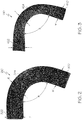
Fig. 2 is an enlarged view similar toFig. 1B , and showing only the closed-angle composite airfoil spar in accordance with an example embodiment. -
Fig. 3 is an enlarged view similar toFig. 1B , and showing only the closed-angle composite airfoil spar in accordance with another example embodiment. -
Fig. 4 is an enlarged view similar toFig. 1B , and showing the closed-angle composite airfoil spar in accordance with still another example embodiment. -
Fig. 5 is a flow diagram illustrating an example method of fabricating a closed-angle composite airfoil spar in accordance with an example embodiment. -
Fig. 6A is an example tooling configuration for implementing the example fabrication method ofFig. 5 . -
Fig. 6B is a sectional view, taken approximately along line "6B-6B", ofFig. 6A , and showing only the closed-angle composite airfoil spar manufactured using the fabrication method ofFig. 5 . -
Fig. 7 is a flow diagram of an aircraft manufacturing and service methodology. -
Fig. 8 is a block diagram of an aircraft. - The present application is directed to closed-angle composite airfoil spars and methods of fabricating the same. The specific composite airfoil spar, fabricating method, and the industry in which the composite airfoil spar and fabricating method are implemented may vary. It is to be understood that the disclosure below provides a number of embodiments or examples for implementing different features of various embodiments. Specific examples of components and arrangements are described to simplify the present disclosure. These are merely examples and are not intended to be limiting.
- By way of example, the disclosure below describes composite airfoil spars and fabricating methods for aircraft. More specifically, the disclosure below describes a composite airfoil spar for use in an airfoil assembly of an aircraft. The composite airfoil spar and method of fabricating the composite airfoil spar may be implemented by an original equipment manufacturer (OEM) for manufacturing composite airfoil spars in compliance with military and space regulations.
- Referring to
Fig. 1A and Fig. 1B (referred to herein collectively as "Fig. 1 "), anexample airfoil assembly 200 embodying a closed-angle composite airfoil spar in accordance with an embodiment is illustrated.Airfoil assembly 200 includes a leading edge (e.g., nose fitting) 202, anupper skin panel 204, and alower skin panel 206. Theleading edge 202 is located at front of theairfoil assembly 200. Theairfoil assembly 200 further includes one spar 210 (front spar) located at front portion of theairfoil assembly 200, and twospars 212, 214 (center spar and aft spar) located at rear portion of theairfoil assembly 200. The onespar 210 located at the front portion is a closed angle spar (i.e., the spar forms an acute angle less than 90°) that faces forward of theairfoil assembly 200. The onespar 210 may have a cross-sectional shape resembling the letter "C," as best shown inFig. 1A . The twospars airfoil assembly 200. While each of the twospars airfoil assembly 200, it is conceivable that the spar be constructed with an acute angle and face aft of theairfoil assembly 200. - A top part of each of the two
spars upper skin panel 204. Similarly, a bottom part of each of the twospars lower skin panel 206. - As best shown in
Fig. 1B , a top part (the elongated flange portion 322) of the onespar 210 may be fastened directly to theupper skin panel 204 and theleading edge 202 proximate thejunction 203 where theupper skin panel 204 and theleading edge 202 meet. Theweb portion 320 of thespar 210 is located aft of thejunction 203 between theupper skin panel 204 and theleading edge 202. - Similarly, a bottom part of the one
spar 210 is fastened directly to thelower skin panel 206 and theleading edge 202 at the junction where thelower skin panel 206 and theleading edge 202 meet. - A spar and a skin panel can be directly fastened together using any suitable technique. For example, a spar and a skin panel can be directly co-bonded together using a suitable bonding material. As another example, a spar and a skin panel can be mechanically fastened together using suitable mechanical fasteners.
- While the
airfoil assembly 200 is shown and described having three spars (i.e., the one closed-angle spar 210 and the two open-angle spars 212, 214), additional closed-angle spars and/or additional open-angle spars, may be included in theairfoil assembly 200 without departing from the scope of the present disclosure. Also, those skilled in the art will appreciate that only a portion of the closed-anglecomposite airfoil spar 210 is shown inFig. 1 , and that the overall size and shape of thecomposite airfoil spar 210 may depend on the end application. The disclosedcomposite airfoil spar 210 may be sized, shaped, and contoured accordingly. - Referring to
Fig. 2 , an enlarged view of a portion of the closed-anglecomposite airfoil spar 210 shown inFig. 1A in accordance with an example embodiment is illustrated. In particular, thecomposite airfoil spar 210 comprises aweb portion 320 having a thickness of 0.220 +/-.005 inches (5.6 +/- 0.1 millimeters). The composite airfoil spar 310 also comprises aflange portion 322 having a thickness of 0.220 +/-.005 inches (5.6 +/- 0.1 millimeters). Theflange portion 322 extends transverse to theweb portion 320. Thecomposite airfoil spar 210 further comprises aradius portion 324 interconnecting the web andflange portions radius portion 324 has a thickness of about 0.210 +/-.005 inches (5.3 +/- 0.1 millimeters). In the example embodiment shown inFig. 3 , theradius portion 324 is an acceptable amount thinner relative to the thickness of theweb portion 320 and the thickness of theflange portion 322 based on design requirements and material properties. In some embodiments, theradius portion 324 is no more than ten (10) percent thinner relative to the thickness of theweb portion 320 and the thickness of theflange portion 322. In some embodiments, theradius portion 324 is no more than five (5) percent thinner relative to the thickness of theweb portion 320 and the thickness of theflange portion 322. Theradius portion 324 has a radius in the range typically between a minimum of about 0.25 inches (0.64 centimeters) and a maximum of about one inch (2.54 centimeters). - Compositionally, the material of the
composite airfoil spar 210 including theweb portion 320, theflange portion 322, and theradius portion 324 comprises fiber reinforced material. The fiber reinforced material may include reinforcing fibers (e.g., carbon fibers, glass fibers or the like) in a matrix material (e.g., thermosetting resin). In some embodiments, the fiber reinforced material comprises reinforcing fibers in an epoxy material (the matrix material). - In a particular implementation, the epoxy material of the fiber reinforced material may be a resin system with curatives that allow the epoxy material to gel relatively early on the temperature scale, such as between 240 °F and 260 °F (e.g., at about 250 °F). Such an epoxy material may facilitate more controlled flow and may be less mobile while crosslinking, thereby reducing (if not eliminating) the radius thinning described herein. As an example of such an epoxy material, the
composite airfoil spar 210 is fabricated from CYCOM® 5320-1 epoxy resin, which is commercially available from Cytec Industries, Inc. CYCOM is a registered trademark of Cytec Industries, Inc. CYCOM® 5320-1 epoxy resin may be cured using an out-of-autoclave process (e.g., in an oven at atmospheric pressure). Other materials are possible in other embodiments. - The
radius portion 324 is shown in the example embodiment ofFig. 2 . The average thickness of theweb portion 320 is 0.220 +/-0.005 inches (5.6 +/- 0.1 millimeters) designated as "W", the average thickness of theflange portion 322 is 0.220 +/-0.005 inches (5.6 +/- 0.1 millimeters) designated as "F", and the average thickness of theradius portion 324 is 0.210 +/-0.005 inches (5.3 +/- 0.1 millimeters) designated as "R". Thus, the average thinning of theradius portion 324 is about five (5) percent of the average thickness of theweb portion 320, and about five (5) percent of the average thickness of theflange portion 322. - In some embodiments, the
radius portion 324 of thespar 210 forms an acute angle (designated as angle "θ" inFig. 2 ) no greater than 90 degrees between theweb portion 320 and theflange portion 322. In some embodiments, theradius portion 324 forms an acute angle θ of at most 80 degrees between theweb portion 320 and theflange portion 322. In other embodiments, theradius portion 324 forms an acute angle θ no greater than 70 degrees between theweb portion 320 and theflange portion 322. In still other embodiments, theradius portion 324 forms an acute angle θ no greater than 60 degrees between theweb portion 320 and theflange portion 322. - Referring to
Fig. 3 , an enlarged view of a portion of the closed-anglecomposite airfoil spar 210 shown inFig. 1A in accordance with another example embodiment is illustrated. In particular, thecomposite airfoil spar 210 comprises aweb portion 420 having a thickness of 0.210 +/-0.005 inches (5.3 +/-0.1 millimeters). Thecomposite airfoil spar 210 also comprises aflange portion 422 having a thickness of 0.220 +/-0.005 inches (5.6 +/- 0.1 millimeters). Theflange portion 422 extends transverse to theweb portion 420. Thecomposite airfoil spar 210 further comprises aradius portion 424 interconnecting the web andflange portions radius portion 424 has a thickness of 0.185 +/-0.005 inches (4.7 +/-0.1 millimeters). In the example embodiment shown inFig. 3 , theradius portion 424 is an acceptable amount thinner relative to the thickness of theweb portion 420 and the thickness of theflange portion 422 based on design requirements and material properties. In some embodiments, theradius portion 424 is no more than fifteen (15) percent thinner relative to the thickness of theweb portion 420 and the thickness of theflange portion 422. Theradius portion 424 has a radius in the range typically between a minimum of about 0.25 inches (0.64 centimeters) and a maximum of about one inch (2.54 centimeters). By making thecomposite airfoil spar 210 using the manufacturing method disclosed herein, the problems associated with radius thinning are avoided or at least minimized. - Compositionally, the material of the
composite airfoil spar 210 including theweb portion 320, theflange portion 322, and theradius portion 324 comprises fiber reinforced material. The fiber reinforced material may include reinforcing fibers (e.g., carbon fibers, glass fibers or the like) in a matrix material (e.g., thermosetting resin). In some embodiments, the fiber reinforced material comprises carbon fiber in an epoxy material. As an example, thecomposite airfoil spar 210 is fabricated from CYCOM® 970 epoxy resin, which commercially available from Cytec Industries, Inc. CYCOM is a registered trademark of Cytec Industries, Inc. Other materials are possible in other embodiments. - The
radius portion 424 is shown in the example embodiment ofFig. 3 . The average thickness of theweb portion 420 is about 0.210 inches (5.3 millimeters) designated as "w", the average thickness of theflange portion 422 is about 0.220 inches (5.6 millimeters) designated as "f", and the average thickness of theradius portion 424 is about 0.185 inches (4.7 millimeters) designated as "r". Thus, the average thinning of theradius portion 424 is about eleven (11) percent of the average thickness of theweb portion 420, and about fifteen (15) percent of the average thickness of theflange portion 422. - In some embodiments, the
radius portion 424 of thespar 210 forms an acute angle (designated as angle "Ø" inFig. 3 ) no greater than 90 degrees between theweb portion 420 and theflange portion 422. In some embodiments, theradius portion 424 forms an acute angle Ø no greater than 80 degrees between theweb portion 420 and theflange portion 422. In other embodiments, theradius portion 424 forms an acute angle Ø no greater than 70 degrees between theweb portion 420 and theflange portion 422. In other embodiments, theradius portion 424 forms an acute angle Ø no greater than 60 degrees between theweb portion 420 and theflange portion 422. - Referring to
Fig. 4 , an enlarged view of a portion of thecomposite airfoil spar 210 shown inFig. 1A in accordance with still another example embodiment is illustrated. Thecomposite airfoil spar 210 comprises aweb portion 520, an elongated (i.e., wider)flange portion 522, and aradius portion 524 interconnecting theweb portion 520 and theflange portion 522. Theflange portion 522 includes ajoggle 526 that is located between theradius portion 524 and end of theflange portion 522. The use ofjoggle 526 is especially advantageous when there is a difference in thickness between leading edge (e.g., nose fitting) 502 andupper skin panel 504. As shown inFig. 4 , theleading edge 502 has a thickness that is less than the thickness of theupper skin panel 504. Thejoggle 526 is angled and formed such that one part of theflange portion 522 abuts flat against theleading edge 502 and another part of theflange portion 522 abuts flat against theupper skin panel 504. By providing theelongated flange portion 522 and locating the composite airfoil spar 210 a little further aft of the airfoil assembly 200 (seeFig. 1A ), thespar 210 can be attached to theleading edge 202 and theupper skin panel 204 without using a splice plate. In other words, theelongated flange portion 522 itself serves as a splice between theleading edge 502 and theskin panel 504. - The following example illustrates a method of fabricating a composite airfoil spar in accordance with an embodiment. The example fabricating method is intended to illustrate, but in no way limits, the scope of the disclosure.
- Referring to
Fig. 5 , a flow diagram 600 is shown illustrating an example method of fabricating example composite airfoil spar 210 ofFig. 1A in accordance with an embodiment. The fabricatingmethod 600 disclosed herein may be employed according to military and space regulations, for example. In some embodiments, the method comprises an out-of-autoclave method, such as described herein. - In
block 602, a number of layers of a fiber reinforced material is applied to a tooling piece to build up layers of the fiber reinforced material. In some embodiments, the layers are applied to the tooling piece to build up a minimum number of layers of the fiber reinforced material on the tooling piece. In some embodiments, the layers are applied with periodic compaction. In some embodiments, the fiber reinforced material can be selected from many commercially available materials. For example, the fiber reinforced material can be selected from one of a carbon fiber reinforced polymer material and a fiber reinforced epoxy material. Inblock 604, a vacuum is drawn about the tooling piece including the layers of the fiber reinforced material on the tooling piece for at least a first predetermined process time. In some embodiments, the drawing a vacuum about the tooling piece including the layers of fiber reinforced material on the tooling piece for at least a first predetermined process time includes drawing a vacuum about the tooling piece including the layers of fiber reinforced material on the tooling piece for a minimum time specified by a manufacturer of the fiber reinforced material. - Then in
block 606, the tooling piece including the layers of the fiber reinforced material on the tooling piece are heated for at least a second predetermined process time. In one particular implementation, heating (block 606) may be an out-of-autoclave process. For example, heating (block 606) may be performed in an oven at atmospheric pressure (e.g., about 1 atm). - In some embodiments, the heating (block 606) the tooling piece including the layers of the fiber reinforced material on the tooling piece for at least a second predetermined process time includes heating the tooling piece including the layers of the fiber reinforced material on the tooling piece for a minimum time specified by a manufacturer of the fiber reinforced material.
- After elapse of the first predetermined process time, the vacuum drawn about the tooling piece including the layers of fiber reinforced material on the tooling piece is released to produce the composite airfoil spar, as shown in
block 608. In some embodiments, the fabricated composite airfoil spar has a closed angle no more than 90 degrees. In some embodiments, the fabricated composite airfoil spar has a closed angle no more than 80 degrees. In other embodiments, the fabricated composite airfoil spar has a closed angle no more than 70 degrees. In still other embodiments, the fabricated composite airfoil spar has a closed angle no more than 60 degrees - In some embodiments, the fabricated composite airfoil spar includes a spar radius portion having a thickness that is an acceptable amount thinner than thickness of a spar web portion on one side of the spar radius portion and thickness of a spar flange portion on an opposite side of the spar radius portion. As an example, the spar radius portion has a thickness that is no more than five (5) percent thinner than the thickness of the spar web portion on the one side of the spar radius portion and the thickness of the spar flange portion on the opposite side of the spar radius portion. The fabricating process then ends.
- The above-described example fabricating method may be carried out using manufacturing systems or apparatus suitable for making composite layered structures such as composite airfoil spars. Referring to
Fig. 6A , anexample tooling piece 700 for implementing the example fabrication method ofFig. 5 is illustrated.Tooling piece 700 is a male tool configuration having a segmentedmandrel assembly 710, such as with threemandrel pieces mandrel pieces end fittings - During the fabrication process, fiber reinforced material is applied in layers onto the temporarily joined three
mandrel pieces mandrel assembly 710 including the layers of fiber reinforced material is then placed in an envelope bag (not shown). A vacuum is drawn about the envelope bag. The part and tool are heated for a predetermined time period and then allowed to cool. The vacuum is then released to produce a composite airfoil spar that is subsequently removed from themandrel assembly 710. - The
example tooling piece 700 ofFig. 6A is a tooling option that is different and relatively inexpensive as compared to known tooling options for making closed-angle spars. Moreover, dimensional tolerance is improved by using thetooling piece 700 ofFig. 6A . The improved dimensional tolerance facilitates tooling assembly, which thereby reduces tooling costs for assembly. - Referring to
Fig. 6B , a sectional view is taken approximately along line "6B-6B", ofFig. 6A , with certain parts removed. More specifically,Fig. 6B shows only the closed-anglecomposite airfoil spar 210 with thejoggle 526 ofFig. 4 manufactured using the fabrication method ofFig. 5 . Theexample tooling piece 700 ofFig. 6A can be modified to fabricate an airfoil spar without a joggle, such as theairfoil spar 210 shown inFig. 1B . - At this point, those skilled in the art will appreciate that using a
tooling piece 700 having a segmentedmandrel assembly 710, as shown inFig. 6A , may facilitate release and separation of the composite airfoil spar 210 from thetooling piece 700 without damaging the curedcomposite airfoil spar 210, thereby facilitating the fabrication of composite airfoil spars having an acute angle θ between theweb portion 320 and theflange portion 322 and, if desired, relatively more complex geometries, as shown inFig. 1B . For example, the acute angle θ may be no greater than 80 degrees and, as shown inFig. 4 , theflange portion 522 may include ajoggle 526. - It should be apparent that although the above description describes a vacuum-based fabricating method to make a composite airfoil spar, it is conceivable that other fabricating methods may be used. Numerous other manufacturing systems or apparatus for making composite airfoil spars are available and, therefore, will not be described.
- It should also be apparent that a composite airfoil spar fabricated in accordance with the above-described example method and preferred materials can use less fiber reinforced material to produce a composite airfoil spar of comparable strength where radius thinning can be reduced at the junction where the web portion and the flange portion come together due to material capabilities. The result is a lower weight composite airfoil spar as compared to known composite airfoil spars that have higher levels of radius thinning. The lower weight composite airfoil spar can be used as a forward-facing spar in the front portion of an airfoil assembly. The forward-facing spar improves airfoil assembly by providing ease of access to fastening elements during assembly.
- It should further be apparent that a composite airfoil spar produced in accordance with above-described example methods is suitable for any type of application. The specific fiber reinforced material of the composite airfoil spar can be selected and tailored depending upon the particular application of the composite airfoil spar.
- Examples of the disclosure may be described in the context of an aircraft manufacturing and
service method 1000, as shown inFig. 7 , and anaircraft 1002, as shown inFig. 8 . During pre-production, the aircraft manufacturing andservice method 1000 may include specification and design 1004 of theaircraft 1002 and material procurement 1006. During production, component/subassembly manufacturing 1008 andsystem integration 1010 of theaircraft 1002 takes place. Thereafter, theaircraft 1002 may go through certification anddelivery 1012 in order to be placed inservice 1014. While in service by a customer, theaircraft 1002 is scheduled for routine maintenance andservice 1016, which may also include modification, reconfiguration, refurbishment and the like. - Each of the processes of
method 1000 may be performed or carried out by a system integrator, a third party, and/or an operator (e.g., a customer). For the purposes of this description, a system integrator may include without limitation any number of aircraft manufacturers and major-system subcontractors; a third party may include without limitation any number of venders, subcontractors, and suppliers; and an operator may be an airline, leasing company, military entity, service organization, and so on. - As shown in
Fig. 8 , theaircraft 1002 produced byexample method 1000 may include anairframe 1018 with a plurality ofsystems 1020 and an interior 1022. Examples of the plurality ofsystems 1020 may include one or more of apropulsion system 1024, anelectrical system 1026, ahydraulic system 1028, and anenvironmental system 1030. Any number of other systems may be included. - The disclosed composite airfoil spars and fabricating methods may be employed during any one or more of the stages of the aircraft manufacturing and
service method 1000. As one example, components or subassemblies corresponding to component/subassembly manufacturing 1008,system integration 1010, and or maintenance andservice 1016 may be fabricated or manufactured using the disclosed composite airfoil spars and fabricating methods. As another example, theairframe 1018 may be constructed using the disclosed composite airfoil spars and fabricating methods. Also, one or more apparatus examples, method examples, or a combination thereof may be utilized during component/subassembly manufacturing 1008 and/orsystem integration 1010, for example, by substantially expediting assembly of or reducing the cost of anaircraft 1002, such as theairframe 1018 and/or the interior 1022. Similarly, one or more of system examples, method examples, or a combination thereof may be utilized while theaircraft 1002 is in service, for example and without limitation, to maintenance andservice 1016. - The disclosed composite airfoil spars and fabricating methods are described in the context of an aircraft; however, one of ordinary skill in the art will readily recognize that the disclosed composite airfoil spars and fabricating methods may be utilized for a variety of applications. For example, the disclosed composite airfoil spars and fabricating methods may be implemented in various types of vehicle including, for example, helicopters, passenger ships, automobiles, marine products (boat, motors, etc.) and the like.
- Embodiments of the present invention are also referred to in the following clauses A1 - F4 which are not to be confused with the claims.
- A1. A closed-angle
composite airfoil spar 210 for anairfoil assembly 200, the composite airfoil spar comprising:- a
web portion 320 having a thickness; and - an
elongated flange portion 322 having a thickness and extending transverse to the web portion and forming an acute angle Θ between the web portion and the elongated flange portion, wherein the elongated flange portion serves as a splice between a leading edge and a skin panel of the airfoil assembly.
- a
- A2. There is also provided, the closed-angle composite airfoil spar of Paragraph A1 wherein the splice is between a
leading edge 202 and anupper skin panel 204 of the airfoil assembly. - A3. There is also provided, the closed-angle composite airfoil spar of Paragraph A2 wherein the leading edge meets the upper skin panel at a
junction 203, and wherein the web portion is located aft of the junction. - A4. There is also provided, the closed-angle composite airfoil spar of Paragraph A1 wherein the acute angle is at most 80 degrees.
- A5. There is also provided, the closed-angle composite airfoil spar of Paragraph A1 having a cross-sectional shape resembling the letter "C."
- A6. There is also provided, the closed-angle composite airfoil spar of Paragraph A1, further comprising a
radius portion 324 interconnecting the web portion and the elongated flange portion, wherein the radius portion is an acceptable amount thinner relative to thickness of the web portion and thickness of the elongated flange portion based on design requirements and material properties. - A7. There is also provided, the closed-angle composite airfoil spar of Paragraph A6 wherein the web portion has a thickness of about 0.220 +/-0.005 inches (5.6 +/-0.1 millimeters), the elongated flange portion has a thickness of about 0.220 +/-0.005 inches (5.6 +/-0.1 millimeters), and the radius portion has a thickness between about 0.210 +/-0.005 inches (5.3 +/-0.1 millimeters).
- According to a further aspect of the present invention, there is provided:
- B1. An
airfoil assembly 200 comprising:- a
leading edge 202;- a
skin panel 204 abutting the leading edge; and - a closed-
angle spar 210 having anelongated flange portion 322 and aweb portion 320 that forms an acute angle Θ between the elongated flange portion and the web portion, wherein the elongated flange portion serves as a splice at a splice point along the elongated flange portion between the leading edge and the skin panel.
- a
- a
- B2. There is also provided, the airfoil assembly of Paragraph B1 wherein the acute angle faces forward of the airfoil assembly after the leading edge and the skin panel are spliced together.
- B3. There is also provided, the airfoil assembly of Paragraph B1 wherein the web portion is located aft of the splice point after the leading edge and the skin panel are spliced together along the elongated flange portion.
- According to a further aspect of the present invention, there is provided:
- C1. A closed-angle
composite airfoil spar 210 for anairfoil assembly 200, the composite airfoil spar comprising:- a
web portion 320 having a thickness; - a
flange portion 322 having a thickness and extending transverse to the web portion; and - a
radius portion 324 interconnecting the web and flange portions, wherein the radius portion is an acceptable amount thinner relative to thickness of the web portion and thickness of the flange portion based on design requirements and material properties.
- a
- C2. There is also provided, the closed-angle composite airfoil spar of Paragraph C1 wherein the radius portion forms an acute angle Θ no greater than 90 degrees between the web portion and the flange portion.
- C3. There is also provided, the closed-angle composite airfoil spar of Paragraph C1 wherein the radius portion forms an acute angle no greater than 80 degrees between the web portion and the flange portion.
- C4. There is also provided, the closed-angle composite airfoil spar of Paragraph C1 having a cross-sectional shape resembling the letter "C."
- C5. There is also provided, the closed-angle composite airfoil spar of Paragraph C1 wherein the flange portion comprises an elongated flange portion that serves as a splice at a splice point along the elongated flange portion between a leading edge and a skin panel of the airfoil assembly.
- C6. There is also provided, the closed-angle composite airfoil spar of Paragraph C1 wherein the material of the web portion, the flange portion, and the radius portion comprises a fiber reinforced material.
- C7. There is also provided, the closed-angle composite airfoil spar of Paragraph C6 wherein the fiber reinforced material comprises an epoxy material.
- C8. There is also provided, the closed-angle composite airfoil spar of Paragraph C7 wherein the epoxy material comprises CYCOM® 5320-1 epoxy resin.
- C9. There is also provided, the closed-angle composite airfoil spar of Paragraph C7 wherein the fiber reinforced material further comprises carbon fibers.
- C10. There is also provided, the closed-angle composite airfoil spar of Paragraph C1 wherein the radius portion is no more than five (5) percent thinner relative to thickness of the web portion and thickness of the flange portion.
- C11. There is also provided, the closed-angle composite airfoil spar of Paragraph C1 wherein the flange portion includes a joggle.
- C12. There is also provided, the closed-angle composite airfoil spar of Paragraph C1 wherein the composite airfoil spar is a forward-facing spar for a front portion of the airfoil assembly.
- According to a further aspect of the present invention, there is provided:
- D1. A
method 600 of fabricating a closed-anglecomposite airfoil spar 210 comprising:
applying 602 layers of a fiber reinforced material to atooling piece 700 to build up layers of the fiber reinforced material on the tooling piece, the tooling piece comprising a plurality of temporarily joinedmandrel pieces - drawing 604 a vacuum about the tooling piece including the layers of fiber reinforced material on the tooling piece for at least a first predetermined process time;
- heating 606 the tooling piece including the layers of the fiber reinforced material on the tooling piece for at least a second predetermined process time; and
- after elapse of the first predetermined process time, releasing 608 the vacuum drawn about the tooling piece including the layers of fiber reinforced material on the tooling piece to produce the closed-angle composite airfoil spar having a closed angle Θ no more than 80 degrees.
- D2. There is also provided, the method of Paragraph D1 wherein the heating the tooling piece including the layers of the fiber reinforced material on the tooling piece for at least the second predetermined process time includes heating the tooling piece including the layers of the fiber reinforced material on the tooling piece using an out-of-autoclave process.
- D3. There is also provided, the method of Paragraph D1 wherein the drawing the vacuum about the tooling piece including the layers of fiber reinforced material on the tooling piece for at least the first predetermined process time includes drawing a vacuum about the tooling piece including the layers of fiber reinforced material on the tooling piece for a minimum time specified by a manufacturer of the fiber reinforced material.
- D4. There is also provided, the method of Paragraph D1 wherein the applying the layers of the fiber reinforced material to the tooling piece to build up the layers of the fiber reinforced material on the tooling piece includes applying the layers of the fiber reinforced material to the tooling piece to build up a minimum number of layers of the fiber reinforced material on the tooling piece.
- D5. There is also provided, the method of Paragraph D1 wherein the applying the layers of the fiber reinforced material to the tooling piece comprises selecting a fiber reinforced material comprising an epoxy material.
- D6. There is also provided, the method of Paragraph D1 wherein the applying the layers of the fiber reinforced material to the tooling piece comprises selecting a fiber reinforced material comprising CYCOM® 5320-1 epoxy resin.
- According to a further aspect of the present invention, there is provided:
- E1. A method of assembling an
airfoil assembly 200 having aleading edge 202 and askin panel 204 that abuts the leading edge, the method comprising:- providing a closed-
angle spar 210 having anelongated flange portion 322 and aweb portion 320 that forms an acute angle Θ between the elongated flange portion and the web portion; and - splicing the leading edge and the skin panel at a splice point along the elongated flange portion of the closed-angle spar.
- providing a closed-
- E2. There is also provided, the method of Paragraph E1 wherein the acute angle faces forward of the airfoil assembly after the leading edge and the skin panel are spliced together.
- E3. There is also provided, the method of Paragraph E1 wherein the web portion is located aft of the splice point where the leading edge and the skin panel are spliced together.
- According to a further aspect of the present invention, there is provided:
- F1. A
method 600 of fabricating a closed-anglecomposite airfoil spar 210 comprising:
applying 602 layers of a fiber reinforced material to atooling piece 700 to build up layers of the fiber reinforced material on the tooling piece and produce the closed-angle composite airfoil spar having an acute angle Θ, wherein the fiber reinforced material comprises an epoxy material that facilitates controlled flow and is relatively less mobile while crosslinking. - F2. There is also provided, the method of Paragraph F1 wherein the epoxy material is a resin system with curatives that allow the epoxy material to gel relatively early on a temperature scale.
- F3. There is also provided, the method of Paragraph F1 wherein the epoxy material gels at a temperature between about 240 °F and about 260°F.
- F4. There is also provided, the method of Paragraph F1 further comprising:
- drawing a vacuum about the tooling piece including the layers of fiber reinforced material on the tooling piece for at least a first predetermined process time;
- heating the tooling piece including the layers of the fiber reinforced material on the tooling piece for at least a second predetermined process time; and
- after elapse of the first predetermined process time, releasing the vacuum drawn about the tooling piece.
- Further, although various embodiments of the disclosed composite airfoil spars and fabricating methods have been shown and described, modifications may occur to those skilled in the art upon reading the specification. The present application includes such modifications and is limited only by the scope of the claims.
Claims (15)
- A closed-angle composite airfoil spar (210) for an airfoil assembly (200), the composite airfoil spar comprising:a web portion (320) having a thickness; andan elongated flange portion (322) having a thickness and extending transverse to the web portion and forming an acute angle (Θ) between the web portion and the elongated flange portion (322), wherein the elongated flange portion is adapted to serve as a splice between a leading edge and a skin panel of the airfoil assembly.
- The closed-angle composite airfoil spar of Claim 1 wherein the splice is between a leading edge (202) and an upper skin panel (204) of the airfoil assembly (200).
- The closed-angle composite airfoil spar of Claim 2 wherein the leading edge meets the upper skin panel at a junction (203), and wherein the web portion (320) is located aft of the junction (203).
- The closed-angle composite airfoil spar of any of Claims 1 - 3 wherein the acute angle is at most 80 degrees.
- The closed-angle composite airfoil spar of any of Claims 1 - 4, having a cross-sectional shape resembling the letter "C" and/or a C-shaped cross-section.
- The closed-angle composite airfoil spar of any of Claims 1 - 5, further comprising a radius portion (324) interconnecting the web portion (320) and the elongated flange portion (322), wherein the radius portion is thinner or is an acceptable amount thinner relative to thickness of the web portion and thickness of the elongated flange portion, particularly based on design requirements and material properties.
- The closed-angle composite airfoil spar of Claim 6 wherein the web portion has a thickness in a range from 2 to 10 mm, particularly of about 0.220 +/-0.005 inches (5.6 +/-0.1 millimeters), the elongated flange portion has a thickness in a range from 2 to 10 mm, particularly of about 0.220 +/-0.005 inches (5.6 +/-0.1 millimeters), and the radius portion has a thickness in a range from 1 to 9 mm, particularly of about 0.210 +/-0.005 inches (5.3 +/- 0.1 millimeters).
- A method (600) of fabricating a closed-angle composite airfoil spar (210) comprising:applying (602) layers of a fiber reinforced material to a tooling piece (700) to build up layers of the fiber reinforced material on the tooling piece, the tooling piece comprising a plurality of temporarily joined mandrel pieces (711, 712, 713);drawing (604) a vacuum about the tooling piece including the layers of fiber reinforced material on the tooling piece for at least a first predetermined process time;heating (606) the tooling piece including the layers of the fiber reinforced material on the tooling piece for at least a second predetermined process time; andafter elapse of the first predetermined process time, releasing (608) the vacuum drawn about the tooling piece including the layers of fiber reinforced material on the tooling piece to produce the closed-angle composite airfoil spar having a closed angle (Θ) no more than 80 degrees.
- The method of Claim 8 wherein the heating (606) the tooling piece including the layers of the fiber reinforced material on the tooling piece for at least the second predetermined process time includes heating the tooling piece including the layers of the fiber reinforced material on the tooling piece using an out-of-autoclave process.
- The method of Claim 8 or 9 wherein the drawing (604) the vacuum about the tooling piece including the layers of fiber reinforced material on the tooling piece for at least the first predetermined process time includes drawing a vacuum about the tooling piece including the layers of fiber reinforced material on the tooling piece for a minimum time specified by a manufacturer of the fiber reinforced material.
- The method of any of Claims 8 - 10 whereinthe applying (602) the layers of the fiber reinforced material to the tooling piece to build up the layers of the fiber reinforced material on the tooling piece includes applying the layers of the fiber reinforced material to the tooling piece to build up a minimum number of layers of the fiber reinforced material on the tooling piece, and/orwherein the layers are applied with periodic compaction.
- The method of any of Claims 8 - 11 wherein the applying (602) the layers of the fiber reinforced material to the tooling piece comprises selecting a fiber reinforced material comprising an epoxy material or a polymer material.
- The method of any of Claims 8 - 12 wherein the applying (602) the layers of the fiber reinforced material to the tooling piece comprises selecting a fiber reinforced material comprising CYCOM® 5320-1 epoxy resin.
- A method of assembling an airfoil assembly (200) having a leading edge (202) and a skin panel (204) that abuts the leading edge, the method comprising:providing a closed-angle spar (210) having an elongated flange portion (322) and a web portion (320) that forms an acute angle (Θ) between the elongated flange portion and the web portion, particularly a closed-angle spar according to any of claims 1 - 7 and/or fabricated according to any of claims 8 - 13; andsplicing the leading edge (202) and the skin panel (204) at a splice point along the elongated flange portion (322) of the closed-angle spar (210).
- The method of Claim 14 wherein the acute angle faces forward of the airfoil assembly after the leading edge and the skin panel are spliced together.
Applications Claiming Priority (1)
| Application Number | Priority Date | Filing Date | Title |
|---|---|---|---|
| US15/610,922 US10647406B2 (en) | 2017-06-01 | 2017-06-01 | Closed-angle composite airfoil spar and method of fabricating the same |
Publications (1)
| Publication Number | Publication Date |
|---|---|
| EP3409580A1 true EP3409580A1 (en) | 2018-12-05 |
Family
ID=62067559
Family Applications (1)
| Application Number | Title | Priority Date | Filing Date |
|---|---|---|---|
| EP18169646.9A Pending EP3409580A1 (en) | 2017-06-01 | 2018-04-26 | Closed-angle composite airfoil spar and method of fabricating the same |
Country Status (5)
| Country | Link |
|---|---|
| US (1) | US10647406B2 (en) |
| EP (1) | EP3409580A1 (en) |
| JP (1) | JP7166777B2 (en) |
| CN (1) | CN108974325B (en) |
| CA (1) | CA3000916C (en) |
Cited By (6)
| Publication number | Priority date | Publication date | Assignee | Title |
|---|---|---|---|---|
| EP3912903A1 (en) * | 2020-05-21 | 2021-11-24 | The Boeing Company | Structural composite airfoils with directly coupled front spars, and related methods |
| US11401026B2 (en) | 2020-05-21 | 2022-08-02 | The Boeing Company | Structural composite airfoils with a single spar, and related methods |
| US11453476B2 (en) | 2020-05-21 | 2022-09-27 | The Boeing Company | Structural composite airfoils with an improved leading edge, and related methods |
| US11554848B2 (en) | 2020-05-21 | 2023-01-17 | The Boeing Company | Structural composite airfoils with a single spar, and related methods |
| US11572152B2 (en) | 2020-05-21 | 2023-02-07 | The Boeing Company | Structural composite airfoils with a single spar, and related methods |
| US12312079B2 (en) | 2021-01-22 | 2025-05-27 | The Boeing Company | Aerodynamic structures and methods of forming aerodynamic structures |
Families Citing this family (5)
| Publication number | Priority date | Publication date | Assignee | Title |
|---|---|---|---|---|
| IL259149B (en) * | 2018-05-03 | 2022-09-01 | Israel Aerospace Ind Ltd | Structural elements made of composite materials |
| CN110757838B (en) * | 2019-10-30 | 2021-12-24 | 航天特种材料及工艺技术研究所 | Composite material wing and forming and assembling integrated forming method |
| US11193377B2 (en) * | 2019-11-26 | 2021-12-07 | General Electric Company | Turbomachine airfoil to reduce laminar separation |
| AU2021204709A1 (en) * | 2020-07-29 | 2022-02-17 | The Boeing Company | Composite thin wingbox architecture for supersonic business jets |
| GB2617556A (en) * | 2022-04-08 | 2023-10-18 | Airbus Operations Ltd | Wing-box structure |
Citations (1)
| Publication number | Priority date | Publication date | Assignee | Title |
|---|---|---|---|---|
| WO2014170693A1 (en) * | 2013-04-18 | 2014-10-23 | Airbus Operations Limited | Winglet |
Family Cites Families (16)
| Publication number | Priority date | Publication date | Assignee | Title |
|---|---|---|---|---|
| US4095322A (en) * | 1976-08-30 | 1978-06-20 | The Boeing Company | Method of fabricating a composite aerodynamic rotorblade assembly |
| JPS591587B2 (en) * | 1979-09-04 | 1984-01-12 | 小島プレス工業株式会社 | Molding equipment for synthetic resin molded products with undercuts |
| US4565595A (en) * | 1981-09-30 | 1986-01-21 | The Boeing Company | Method of making composite aircraft wing |
| US4657615A (en) * | 1984-08-20 | 1987-04-14 | The Boeing Company | Composite leading edge/spar member for an aircraft control surface |
| JP2000043796A (en) * | 1998-07-30 | 2000-02-15 | Japan Aircraft Development Corp | Wing-shaped structure of composite material and molding method thereof |
| JP4652160B2 (en) * | 2005-07-11 | 2011-03-16 | 川崎重工業株式会社 | Lamination composite straightening jig, straightening method, and molded product |
| US8544800B2 (en) * | 2005-07-21 | 2013-10-01 | The Boeing Company | Integrated wingtip extensions for jet transport aircraft and other types of aircraft |
| JP5251004B2 (en) * | 2006-05-31 | 2013-07-31 | 東レ株式会社 | Preform manufacturing method, preform, and fiber reinforced plastic girder |
| GB0712549D0 (en) * | 2007-06-29 | 2007-08-08 | Airbus Uk Ltd | Improvements in elongate composite structural members |
| US7871041B2 (en) * | 2007-10-17 | 2011-01-18 | Lockheed Martin Corporation | System, method, and apparatus for leading edge structures and direct manufacturing thereof |
| US8364389B2 (en) * | 2009-02-02 | 2013-01-29 | Apple Inc. | Systems and methods for integrating a portable electronic device with a bicycle |
| GB201120707D0 (en) * | 2011-12-01 | 2012-01-11 | Airbus Operations Ltd | Leading edge structure |
| US9145203B2 (en) * | 2012-10-31 | 2015-09-29 | The Boeing Company | Natural laminar flow wingtip |
| US9144841B1 (en) * | 2012-11-15 | 2015-09-29 | The Boeing Company | In-mold metallization of composite structures |
| US8973871B2 (en) * | 2013-01-26 | 2015-03-10 | The Boeing Company | Box structures for carrying loads and methods of making the same |
| CN205931233U (en) * | 2016-06-13 | 2017-02-08 | 中国航空工业集团公司西安飞机设计研究所 | Overlap joint structure of airfoil covering on spar edge strip |
-
2017
- 2017-06-01 US US15/610,922 patent/US10647406B2/en active Active
-
2018
- 2018-04-04 JP JP2018072239A patent/JP7166777B2/en active Active
- 2018-04-11 CA CA3000916A patent/CA3000916C/en active Active
- 2018-04-26 EP EP18169646.9A patent/EP3409580A1/en active Pending
- 2018-05-28 CN CN201810527528.2A patent/CN108974325B/en active Active
Patent Citations (1)
| Publication number | Priority date | Publication date | Assignee | Title |
|---|---|---|---|---|
| WO2014170693A1 (en) * | 2013-04-18 | 2014-10-23 | Airbus Operations Limited | Winglet |
Non-Patent Citations (6)
| Title |
|---|
| "Manufacturing Techniques for Polymer Matrix Composites (PMCs)", 1 January 2012, ELSEVIER, ISBN: 978-0-85709-067-6, article K.-T. HSIAO ET AL: "Vacuum assisted resin transfer molding (VARTM) in polymer matrix composites", pages: 310 - 347, XP055477696, DOI: 10.1533/9780857096258.3.310 * |
| DEREK J QUADE ET AL: "Comparison of Autoclave and Out-of-Autoclave Composites", NASA TECHNICAL REPORTS SERVER, 11 October 2010 (2010-10-11), XP055477986 * |
| JULIEN CAUBERGHS: "Out-of-Autoclave Manufacturing of Aerospace Representative Parts", 1 January 2012 (2012-01-01), XP055477990, ISBN: 978-0-494-84154-9, Retrieved from the Internet <URL:http://digitool.library.mcgill.ca/thesisfile106593.pdf> [retrieved on 20180524] * |
| KAREN MASON: "Autoclave Quality Outside The Autoclave? : CompositesWorld", 3 January 2006 (2006-01-03), XP055477980, Retrieved from the Internet <URL:https://www.compositesworld.com/articles/autoclave-quality-outside-the-autoclave> [retrieved on 20180524] * |
| T. H HOU ET AL: "Evaluation of Double-Vacuum-Bag Process For Composite Fabrication", 16 January 2004 (2004-01-16), XP055477826, Retrieved from the Internet <URL:https://ntrs.nasa.gov/archive/nasa/casi.ntrs.nasa.gov/20040073434.pdf> [retrieved on 20180523] * |
| WWW CYTEC INDUSTRIES INC.: "CYCOM 5320-1 Epoxy Resin System", 1 October 2015 (2015-10-01), XP055477825, Retrieved from the Internet <URL:https://www.cytec.com/sites/default/files/datasheets/CYCOM%205320-1%20Rev%20CR5.pdf> [retrieved on 20180523] * |
Cited By (6)
| Publication number | Priority date | Publication date | Assignee | Title |
|---|---|---|---|---|
| EP3912903A1 (en) * | 2020-05-21 | 2021-11-24 | The Boeing Company | Structural composite airfoils with directly coupled front spars, and related methods |
| US11401026B2 (en) | 2020-05-21 | 2022-08-02 | The Boeing Company | Structural composite airfoils with a single spar, and related methods |
| US11453476B2 (en) | 2020-05-21 | 2022-09-27 | The Boeing Company | Structural composite airfoils with an improved leading edge, and related methods |
| US11554848B2 (en) | 2020-05-21 | 2023-01-17 | The Boeing Company | Structural composite airfoils with a single spar, and related methods |
| US11572152B2 (en) | 2020-05-21 | 2023-02-07 | The Boeing Company | Structural composite airfoils with a single spar, and related methods |
| US12312079B2 (en) | 2021-01-22 | 2025-05-27 | The Boeing Company | Aerodynamic structures and methods of forming aerodynamic structures |
Also Published As
| Publication number | Publication date |
|---|---|
| JP2018203229A (en) | 2018-12-27 |
| CN108974325A (en) | 2018-12-11 |
| US10647406B2 (en) | 2020-05-12 |
| CA3000916C (en) | 2023-09-26 |
| US20180346094A1 (en) | 2018-12-06 |
| JP7166777B2 (en) | 2022-11-08 |
| BR102018010801A2 (en) | 2018-12-18 |
| CN108974325B (en) | 2023-04-25 |
| CA3000916A1 (en) | 2018-12-01 |
Similar Documents
| Publication | Publication Date | Title |
|---|---|---|
| EP3409580A1 (en) | Closed-angle composite airfoil spar and method of fabricating the same | |
| US9636876B2 (en) | Method, device and apparatus for vacuum forming composite laminates | |
| EP2871050B1 (en) | Laminated composite radius filler with geometric shaped filler element and method of forming the same | |
| US9724891B2 (en) | Bead-stiffened composite parts | |
| EP2734441B1 (en) | Flexible truss frame | |
| EP2803474B1 (en) | Composite structure and method | |
| EP3427934B1 (en) | Structural pre-cured repair patch for repair to highly loaded primary and secondary structural components | |
| EP3875256B1 (en) | Method and system for manufacturing a cured composite structure | |
| CN110104202B (en) | Composite aircraft manufacturing tool using articulated mandrels | |
| US20190210308A1 (en) | Method for repairing a composite stringer with a composite repair cap | |
| US11673644B2 (en) | Composite spars with integrated sacrificial surfaces | |
| EP2848518B1 (en) | Carbon fiber reinforced polymer cargo beam with integrated cargo stanchions and c-splices | |
| US11981426B2 (en) | Composite spars with integrated sacrificial surfaces | |
| US11685503B2 (en) | Stringer assemblies and methods of forming thereof | |
| US11377851B2 (en) | Stringer and associated composite structure and method for reinforcing a base structure | |
| BR102018010801B1 (en) | CLOSED-ANGLE COMPOSITE AIRFOIL SPARTER, AND, METHOD FOR MANUFACTURING A CLOSED-ANGLE COMPOSITE AIRFOIL SPARTER |
Legal Events
| Date | Code | Title | Description |
|---|---|---|---|
| PUAI | Public reference made under article 153(3) epc to a published international application that has entered the european phase |
Free format text: ORIGINAL CODE: 0009012 |
|
| STAA | Information on the status of an ep patent application or granted ep patent |
Free format text: STATUS: REQUEST FOR EXAMINATION WAS MADE |
|
| 17P | Request for examination filed |
Effective date: 20180426 |
|
| AK | Designated contracting states |
Kind code of ref document: A1 Designated state(s): AL AT BE BG CH CY CZ DE DK EE ES FI FR GB GR HR HU IE IS IT LI LT LU LV MC MK MT NL NO PL PT RO RS SE SI SK SM TR |
|
| AX | Request for extension of the european patent |
Extension state: BA ME |
|
| STAA | Information on the status of an ep patent application or granted ep patent |
Free format text: STATUS: EXAMINATION IS IN PROGRESS |
|
| 17Q | First examination report despatched |
Effective date: 20211105 |
|
| RAP3 | Party data changed (applicant data changed or rights of an application transferred) |
Owner name: THE BOEING COMPANY |
|
| GRAP | Despatch of communication of intention to grant a patent |
Free format text: ORIGINAL CODE: EPIDOSNIGR1 |
|
| STAA | Information on the status of an ep patent application or granted ep patent |
Free format text: STATUS: GRANT OF PATENT IS INTENDED |
|
| INTG | Intention to grant announced |
Effective date: 20250709 |
|
| GRAJ | Information related to disapproval of communication of intention to grant by the applicant or resumption of examination proceedings by the epo deleted |
Free format text: ORIGINAL CODE: EPIDOSDIGR1 |
|
| STAA | Information on the status of an ep patent application or granted ep patent |
Free format text: STATUS: EXAMINATION IS IN PROGRESS |
|
| INTC | Intention to grant announced (deleted) | ||
| P01 | Opt-out of the competence of the unified patent court (upc) registered |
Free format text: CASE NUMBER: UPC_APP_8042_3409580/2025 Effective date: 20250926 |
|
| GRAP | Despatch of communication of intention to grant a patent |
Free format text: ORIGINAL CODE: EPIDOSNIGR1 |
|
| STAA | Information on the status of an ep patent application or granted ep patent |
Free format text: STATUS: GRANT OF PATENT IS INTENDED |
|
| INTG | Intention to grant announced |
Effective date: 20260126 |
|
| GRAS | Grant fee paid |
Free format text: ORIGINAL CODE: EPIDOSNIGR3 |
|
| GRAA | (expected) grant |
Free format text: ORIGINAL CODE: 0009210 |
|
| STAA | Information on the status of an ep patent application or granted ep patent |
Free format text: STATUS: THE PATENT HAS BEEN GRANTED |