EP3409527A1 - In-vehicle electronic device - Google Patents
In-vehicle electronic device Download PDFInfo
- Publication number
- EP3409527A1 EP3409527A1 EP18174866.6A EP18174866A EP3409527A1 EP 3409527 A1 EP3409527 A1 EP 3409527A1 EP 18174866 A EP18174866 A EP 18174866A EP 3409527 A1 EP3409527 A1 EP 3409527A1
- Authority
- EP
- European Patent Office
- Prior art keywords
- drive
- moving member
- arm
- drive arm
- electronic device
- Prior art date
- Legal status (The legal status is an assumption and is not a legal conclusion. Google has not performed a legal analysis and makes no representation as to the accuracy of the status listed.)
- Granted
Links
Images

Classifications
-
- B—PERFORMING OPERATIONS; TRANSPORTING
- B60—VEHICLES IN GENERAL
- B60K—ARRANGEMENT OR MOUNTING OF PROPULSION UNITS OR OF TRANSMISSIONS IN VEHICLES; ARRANGEMENT OR MOUNTING OF PLURAL DIVERSE PRIME-MOVERS IN VEHICLES; AUXILIARY DRIVES FOR VEHICLES; INSTRUMENTATION OR DASHBOARDS FOR VEHICLES; ARRANGEMENTS IN CONNECTION WITH COOLING, AIR INTAKE, GAS EXHAUST OR FUEL SUPPLY OF PROPULSION UNITS IN VEHICLES
- B60K35/00—Instruments specially adapted for vehicles; Arrangement of instruments in or on vehicles
- B60K35/50—Instruments characterised by their means of attachment to or integration in the vehicle
- B60K35/53—Movable instruments, e.g. slidable
-
- B—PERFORMING OPERATIONS; TRANSPORTING
- B60—VEHICLES IN GENERAL
- B60K—ARRANGEMENT OR MOUNTING OF PROPULSION UNITS OR OF TRANSMISSIONS IN VEHICLES; ARRANGEMENT OR MOUNTING OF PLURAL DIVERSE PRIME-MOVERS IN VEHICLES; AUXILIARY DRIVES FOR VEHICLES; INSTRUMENTATION OR DASHBOARDS FOR VEHICLES; ARRANGEMENTS IN CONNECTION WITH COOLING, AIR INTAKE, GAS EXHAUST OR FUEL SUPPLY OF PROPULSION UNITS IN VEHICLES
- B60K35/00—Instruments specially adapted for vehicles; Arrangement of instruments in or on vehicles
- B60K35/20—Output arrangements, i.e. from vehicle to user, associated with vehicle functions or specially adapted therefor
- B60K35/21—Output arrangements, i.e. from vehicle to user, associated with vehicle functions or specially adapted therefor using visual output, e.g. blinking lights or matrix displays
- B60K35/22—Display screens
-
- B—PERFORMING OPERATIONS; TRANSPORTING
- B60—VEHICLES IN GENERAL
- B60K—ARRANGEMENT OR MOUNTING OF PROPULSION UNITS OR OF TRANSMISSIONS IN VEHICLES; ARRANGEMENT OR MOUNTING OF PLURAL DIVERSE PRIME-MOVERS IN VEHICLES; AUXILIARY DRIVES FOR VEHICLES; INSTRUMENTATION OR DASHBOARDS FOR VEHICLES; ARRANGEMENTS IN CONNECTION WITH COOLING, AIR INTAKE, GAS EXHAUST OR FUEL SUPPLY OF PROPULSION UNITS IN VEHICLES
- B60K35/00—Instruments specially adapted for vehicles; Arrangement of instruments in or on vehicles
- B60K35/60—Instruments characterised by their location or relative disposition in or on vehicles
-
- B—PERFORMING OPERATIONS; TRANSPORTING
- B60—VEHICLES IN GENERAL
- B60R—VEHICLES, VEHICLE FITTINGS, OR VEHICLE PARTS, NOT OTHERWISE PROVIDED FOR
- B60R11/00—Arrangements for holding or mounting articles, not otherwise provided for
-
- B—PERFORMING OPERATIONS; TRANSPORTING
- B60—VEHICLES IN GENERAL
- B60R—VEHICLES, VEHICLE FITTINGS, OR VEHICLE PARTS, NOT OTHERWISE PROVIDED FOR
- B60R11/00—Arrangements for holding or mounting articles, not otherwise provided for
- B60R11/02—Arrangements for holding or mounting articles, not otherwise provided for for radio sets, television sets, telephones, or the like; Arrangement of controls thereof
- B60R11/0229—Arrangements for holding or mounting articles, not otherwise provided for for radio sets, television sets, telephones, or the like; Arrangement of controls thereof for displays, e.g. cathodic tubes
- B60R11/0235—Arrangements for holding or mounting articles, not otherwise provided for for radio sets, television sets, telephones, or the like; Arrangement of controls thereof for displays, e.g. cathodic tubes of flat type, e.g. LCD
-
- B—PERFORMING OPERATIONS; TRANSPORTING
- B60—VEHICLES IN GENERAL
- B60R—VEHICLES, VEHICLE FITTINGS, OR VEHICLE PARTS, NOT OTHERWISE PROVIDED FOR
- B60R11/00—Arrangements for holding or mounting articles, not otherwise provided for
- B60R2011/0001—Arrangements for holding or mounting articles, not otherwise provided for characterised by position
- B60R2011/0003—Arrangements for holding or mounting articles, not otherwise provided for characterised by position inside the vehicle
- B60R2011/0005—Dashboard
-
- B—PERFORMING OPERATIONS; TRANSPORTING
- B60—VEHICLES IN GENERAL
- B60R—VEHICLES, VEHICLE FITTINGS, OR VEHICLE PARTS, NOT OTHERWISE PROVIDED FOR
- B60R11/00—Arrangements for holding or mounting articles, not otherwise provided for
- B60R2011/0042—Arrangements for holding or mounting articles, not otherwise provided for characterised by mounting means
- B60R2011/008—Adjustable or movable supports
- B60R2011/0084—Adjustable or movable supports with adjustment by linear movement in their operational position
-
- B—PERFORMING OPERATIONS; TRANSPORTING
- B60—VEHICLES IN GENERAL
- B60R—VEHICLES, VEHICLE FITTINGS, OR VEHICLE PARTS, NOT OTHERWISE PROVIDED FOR
- B60R11/00—Arrangements for holding or mounting articles, not otherwise provided for
- B60R2011/0042—Arrangements for holding or mounting articles, not otherwise provided for characterised by mounting means
- B60R2011/008—Adjustable or movable supports
- B60R2011/0092—Adjustable or movable supports with motorization
Definitions
- the present invention relates to an in-vehicle electronic device that reciprocates a device main body such as a display.
- WO 2013/189610 A2 describes an invention related to an in-vehicle screen adjustment device as an in-vehicle electronic device.
- a housing is provided with a pair of guide shafts, and a screen member is slidably supported by the guide shafts.
- the housing is provided with a pair of rotating gears, a pair of link members are rotated by the rotating gears, and the screen member is moved between a lowered position and a raised position.
- a pair of thrust members sandwiching the guide shaft are provided inside a bracket provided in the screen member, and each thrust member is urged against the guide shaft by a spring member. This structure prevents rattling between the screen member and the guide shaft.
- An object of the present invention is to provide an in-vehicle electronic device capable of applying an appropriate load between a moving member and a guide shaft without providing a special urging member between the moving member and the guide member.
- the invention relates to an in-vehicle electronic device according to the appended claims. Embodiments are disclosed in the dependent claims.
- an in-vehicle electronic device includes at least one guide portion provided in a fixed portion, a moving member reciprocatably supported by the at least one guide portion, a device main body mounted on the moving member, and a drive portion configured to reciprocate the moving member along the at least one guide portion.
- the drive portion is provided with at least one drive arm supported rotatably about a rotation shaft located between the drive portion and the fixed portion and configured to apply reciprocating force to the moving member, and a drive source configured to rotate the at least one drive arm.
- the at least one drive arm has an elastic portion, and the moving member is urged against the at least one guide portion by elastic force exerted by the deflection of the elastic portion in the direction of the axial center line of the rotation shaft.
- the at least one guide portion include a pair of guide portions
- the at least one drive arm include a pair of drive arms
- the elastic portions be directed toward the respective drive arms
- the moving member be urged against the respective guide portions by the pair of drive arms.
- At least part of the at least one drive arm be formed of a metal plate, at least part of the metal plate be the elastic portion, and deflection be imparted to the elastic portion.
- the at least one drive arm have a proximal portion rotatably supported by the fixed portion, a distal portion connected to the moving member, and the elastic portion located between the proximal portion and the distal portion, and the cross-sectional area of the proximal portion be larger than the cross-sectional area of the elastic portion.
- the at least one drive arm have an arm portion forming the elastic portion and made of a metal plate, and a gear portion integrated with the arm portion in the proximal portion and made of synthetic resin.
- the distal portion be connected via a link member or directly to the moving member.
- the device main body be a display, and the display be moved between a non-display position and a display position by the reciprocating movement of the moving member.
- an appropriate frictional force can be applied between the moving member and the guide portion by the drive arm that applies a moving force to the moving member. Therefore, unlike the conventional art, spring members for urging the moving member are unnecessary, the number of parts can be reduced, the assembly man-hours can be reduced, and cost reduction can be achieved.
- the spring constant can be appropriately set, and a balanced load can be applied to the plurality of bearing portions between the moving member and the guide portion by the drive arm, and the moving member can be reciprocated smoothly.
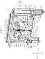
- Fig. 1 is a perspective view showing a state in which a display 12 serving as a device main body is lowered and in a retracted position in an in-vehicle electronic device 1 according to an embodiment of the present invention.
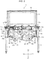
- Fig. 2 is a front view showing a state in which the display 12 projects upward and is in a display position in the in-vehicle electronic device 1.
- the in-vehicle electronic device 1 has a fixed frame 3.
- a cover member 4 is fixed to the upper part of the fixed frame 3.
- a front frame (not shown) is fixed to the front side in the figure of the fixed frame 3 shown in Fig. 1 .
- the fixed frame 3, the front frame and the cover member 4 constitute a fixed portion 2.
- the fixed frame 3, the front frame and the cover member 4 are all made of synthetic resin. Alternatively, only the cover member 4 is made of a metal plate.
- the in-vehicle electronic device 1 is installed in an instrument panel, a center console, or the like in a vehicle interior of an automobile.
- the fixed frame 3 and the front frame are fixed inside the instrument panel or the center console, and the cover member 4 is fixed in the vicinity of the upper surface of the instrument panel or the center console.
- Fig. 1 shows a retracted position in which the moving member 10 and the display 12 serving as a device main body are lowered in the Z1 direction, and the display 12 is hidden inside the housing of the instrument panel or the center console.
- Fig. 2 shows a display position (or use position) in which the moving member 10 and the display 12 are raised, and the display 12 projects upward (in the Z2 direction) from the upper surface of the instrument panel or the center console.
- a first guide portion 5 and a second guide portion 6 are fixed to the fixed frame 3.
- the first guide portion 5 and the second guide portion 6 are guide shafts made of metal and having a circular cross section.
- the first guide portion 5 and the second guide portion 6 are parallel to each other and extend linearly in the vertical direction (Z1-Z2 direction), and their upper ends and lower ends are fixed to the fixed frame 3.
- the in-vehicle electronic device 1 is provided with a moving member (lifting member) 10.
- the moving member 10 is made of synthetic resin, a first bearing portion 11a and a second bearing portion 11b are formed vertically spaced apart from each other on the right side (Y1 side) in the figure, and a third bearing portion 11c is formed on the left side (Y2 side) in the figure.
- Sliding type thrust bearings are held by the bearing portions 11a, 11b, and 11c, the thrust bearings held by the first bearing portion 11a and the second bearing portion 11b are slidably attached to the first guide portion 5, and the thrust bearing held by the third bearing portion 11c is slidably attached to the second guide portion 6.
- the display 12 as a device main body is mounted on the moving member 10.
- the display 12 is a color liquid crystal display panel or an electroluminescence panel and has a display screen 13. As shown in Fig. 2 , when the display 12 serving as a device main body moves upward to the display position together with the moving member 10, the display screen 13 projects above the upper surface of the instrument panel or the center console, and the display screen 13 can be visually observed in the vehicle interior.
- the in-vehicle electronic device 1 is provided with a drive portion 20.
- the drive portion 20 has a first drive arm 21 located on the Y2 side, a second drive arm 26 located on the Y1 side, and a drive source 30 located above (Z2 direction) the drive arms 21 and 26.
- the front frame (not shown) is provided on the front side in the figure of the fixed frame 3, and the first drive arm 21, the second drive arm 26, and the drive source 30 are supported by the front frame.
- the first drive arm 21 has an arm portion 22, a gear portion 23, and a connecting portion 24.
- the arm portion 22 is formed of a metal plate, and in the embodiment, it is formed of a stainless steel plate (SUS 304).
- the gear portion 23 and the connecting portion 24 are made of synthetic resin, and the gear portion 23 and the connecting portion 24 are integrated with the arm portion 22 by a so-called insert molding method.
- the first drive arm 21 is roughly divided into a proximal portion 21a, a distal portion 21b, and an elastic portion 21c.
- the elastic portion 21c is formed by the arm portion 22 made of a metal plate, and its width dimension is constant over its entire length. However, the elastic portion 21c may have such a shape that its width dimension gradually decreases toward the distal portion.
- the proximal portion 21a is constituted by a proximal side portion 22a of the arm portion 22 and the gear portion 23. In the arm portion 22, the width dimension of the proximal side portion 22a is larger than the width dimension of the arm portion 22 in the elastic portion 21c. That is, in the proximal side portion 22a, the width dimension gradually increases toward the gear portion 23.
- a sector gear portion 23a and a bearing hole 23b are formed in the gear portion 23.
- the pitch circle of the sector gear portion 23a coincides with an arc locus centered at the bearing hole 23b.
- a spring hook portion 23c is integrally formed in the gear portion 23.
- a connecting hole 24a is integrally formed in the connecting portion 24 provided in the distal portion 21b.
- an arm portion 27 formed of a stainless steel plate (SUS 304), and a gear portion 28 and a connecting portion 29 made of synthetic resin are integrated by a so-called insert molding method.
- the second drive arm 26 is roughly divided into a proximal portion 26a, a distal portion 26b, and an elastic portion 26c.
- the width dimension of the arm portion 27 is constant.
- the proximal portion 26a is constituted by a proximal side portion 27a of the arm portion 27 and the gear portion 28, and the width dimension of the proximal side portion 27a is larger than the width dimension of the arm portion 27 in the elastic portion 26c.
- the gear portion 28 has a sector gear portion 28a, a bearing hole 28b, and a spring hook portion 28c.
- a connecting hole 29a is formed in the connecting portion 29 made of synthetic resin integrated with the distal portion 26b.
- rotation shafts 15 and 16 are fixed to the front frame (not shown) provided on the front side of the fixed frame 3.
- the bearing hole 23b formed in the gear portion 23 of the first drive arm 21 is rotatably supported by the rotation shaft 15, and the bearing hole 28b formed in the gear portion 28 of the second drive arm 26 is rotatably supported by the rotation shaft 16.
- the sector gear portion 23a provided in the proximal portion 21a of the first drive arm 21 and the sector gear portion 28a provided in the proximal portion 26a of the second drive arm 26 are in mesh with each other.
- the connecting portion 24 provided in the distal portion 21b of the first drive arm 21 is connected to the Y1 side end of the moving member 10 via a link member 17.
- a connecting shaft 17a provided at one end of the link member 17 is rotatably inserted into the connecting hole 24a formed in the connecting portion 24 of the first drive arm 21.
- the other end of the link member 17 and the Y1 side end of the moving member 10 are rotatably connected via a supporting and connecting shaft 17b.
- the connecting portion 29 provided in the distal portion 26b of the second drive arm 26 is connected to the Y2 side end of the moving member 10 via a link member 18.
- a connecting shaft 18a provided at one end of the link member 18 is rotatably inserted into the connecting hole 29a formed in the connecting portion 29 of the second drive arm 26.
- the other end of the link member 18 and the Y2 side end of the moving member 10 are rotatably connected via a supporting and connecting shaft 18b.
- an elongated hole may be formed in the connecting portion 24 of the first drive arm 21, the supporting and connecting shaft 17b provided in the moving member 10 may be inserted into the elongated hole, and the first drive arm 21 and the moving member 10 may be directly connected.
- an elongated hole may formed in the connecting portion 29 of the distal portion 26b of the second drive arm 26, the supporting and connecting shaft 18b may be inserted into the elongated hole, and the second drive arm 26 may be directly connected to the moving member 10.
- the drive source 30 has a drive bracket 31.
- the drive bracket 31 is fixed to the front frame (not shown).
- a drive motor 32, a reduction gear 33 and a drive gear 34 are supported by the drive bracket 31.
- a worm gear 35 is fixed to the output shaft of the drive motor 32, the rotational output of the drive motor 32 is decelerated by the worm gear 35 and the reduction gear 33, and the drive gear 34 is driven.
- a pinion gear whose pitch circle is smaller than the drive gear 34 is formed integrally with the drive gear 34, and this pinion gear meshes with the sector gear portion 23a of the first drive arm 21.
- a tension coil spring 19a is hooked between the front frame (not shown) and the spring hook portion 23c of the first drive arm 21, and a tension coil spring 19b is hooked between the front frame and the spring hook portion 28c of the second drive arm 26.
- the urging force of the tension coil springs 19a and 19b suppresses the engagement backlash between the sector gear portion 23a and the sector gear portion 28a and the backlash between the sector gear portion 23a and the pinion gear.
- a retracted position detection switch SW1 and a display position detection switch SW2 are provided vertically spaced apart from each other.
- a detection protrusion 11d is formed integrally with the moving member 10, and the retracted position detection switch SW1 and the display position detection switch SW2 are caused to operate by the detection protrusion 11d.
- the bearing hole 23b of the gear portion 23 is supported by the rotation shaft 15 fixed to the front frame, and the connecting portion 24 of the distal portion 21b is connected to the Y1 side end of the moving member 10 via the link member 17.
- the first drive arm 21 is attached in a state where the connecting portion 24 is displaced with respect to the gear portion 23 in the ⁇ direction shown in Fig. 4A . Due to this displacement ⁇ , the arm portion 22 formed of a stainless steel plate is deflected in the plate thickness direction, and due to the elastic reaction force thereof, an urging force F1 directed toward the back side of the plane of the paper in Fig. 2 is applied from the connecting portion 24 to the Y1 side end of the moving member 10.
- the displacement ⁇ and the deflection direction of the arm portion 22 are parallel to the axial center line of the rotation shaft 15 of the first drive arm 21 and are perpendicular to the direction in which the first guide portion 5 extends. Therefore, the urging force F1 is always constant even when the rotation angle of the first drive arm 21 is changed.
- deflection occurs mainly in the elastic portion 21c having a small width dimension and small cross-sectional area, and the urging force F1 is applied to the movable member 10 due to this deflection.
- deflection also occurs in the proximal side portion 22a of the arm portion 22, since the width dimension and cross-sectional area of the proximal side portion 22a are larger than those of the elastic portion 21c, the deflection in the proximal side portion 22a is smaller than the deflection in the elastic portion 21c.
- the width dimension of the proximal side portion 22a gradually increases toward the gear portion 23, the deflection and stress occurring in the arm portion 22 is less likely to be transmitted to the gear portion 23, and deformation or the like of the sector gear portion 23a can be suppressed.
- the bearing hole 28b of the gear portion 28 is supported by the rotation shaft 16 fixed to the front frame, and the connecting portion 29 of the distal portion 26b is connected to the Y2 side end of the moving member 10 via the link member 18.
- the connecting portion 29 is displaced with respect to the gear portion 28 in the ⁇ direction shown in Fig. 3B . Due to this displacement ⁇ , the arm portion 27 formed of a stainless steel plate is deflected in the plate thickness direction, and due to the elastic reaction force thereof, an urging force F2 directed toward the back side of the plane of the paper in Fig. 2 is applied from the connecting portion 29 to the Y2 side end of the moving member 10.
- deflection occurs mainly in the elastic portion 26c having a small width dimension and small cross-sectional area, and the urging force F2 is applied to the movable member 10. Since the width dimension and cross-sectional area of the proximal side portion 27a of the arm portion 27 are large, the deflection in this portion is smaller than that of the elastic portion 26c. Therefore, the deflection and stress occurring in the elastic portion 26c is less likely to be transmitted to the gear portion 28, and deformation or the like of the sector gear portion 28a can be suppressed.
- Fig. 1 shows the retracted position in which the display 12 serving as a device main body is lowered.
- the retracted position detection switch SW1 is caused to operate by the detection protrusion 11d provided at the Y1 side end the of the moving member 10, and the drive motor 32 is stopped based on the detection signal.
- the rotating force of the first drive arm 21 is transmitted to the moving member 10 via the link member 17, the rotating force of the second drive arm 26 is transmitted to the moving member 10 via the link member 18, and the moving member 10 is lifted to the display position as shown in Fig. 2 .
- the display position detection switch SW2 is caused to operate by the detection protrusion 11d provided in the moving member 10, a stop command is given to the motor driver from the control unit.
- the display 12 projects upward from the cover member 4 and is in the display position in which the display screen 13 is exposed.
- the first bearing portion 11a and the second bearing portion 11b of the moving member 10 stably abut on and slide on the first guide portion 5, and the third bearing portion 11c stably abuts on and slides on the second guide portion 6.
- occurrence of stick-slip when the moving member 10 moves up and down can be prevented, and the moving member 10 can be smoothly raised and lowered.
- rattling due to the clearance between the bearing portions 11a, 11b, and 11c provided in the moving member 10 and the guide portions 5 and 6 can be suppressed.
- the in-vehicle electronic device 1 is not provided with spring members only for the purpose of restricting rattling between the moving member 10 and the guide portions 5 and 6, the number of parts can be reduced, the assembly man-hours can be reduced, and the manufacturing cost can be suppressed.
- the elastic portion 21c of the arm portion 22 of the first drive arm 21 and the elastic portion 26c of the arm portion 26 of the second drive arm 26 can be formed long, even if the spring constants of the arm portions 22 and 26 are made relatively small, the urging forces F1 and F2 can be set to sufficient magnitudes. As a result, it is easy to set the balance between the urging force F1 and the urging force F2, and fluctuation of the urging force F1 and the urging force F2 is unlikely to occur.
- the device main body supported by the moving member 10 is a display
- the device main body may be other than a display 12, for example, a disk tray, a recording medium attachment portion therefor, or a tray on which a glass is placed.
Landscapes
- Engineering & Computer Science (AREA)
- Mechanical Engineering (AREA)
- Chemical & Material Sciences (AREA)
- Combustion & Propulsion (AREA)
- Transportation (AREA)
- Fittings On The Vehicle Exterior For Carrying Loads, And Devices For Holding Or Mounting Articles (AREA)
Abstract
Description
- The present invention relates to an in-vehicle electronic device that reciprocates a device main body such as a display.
-
WO 2013/189610 A2 describes an invention related to an in-vehicle screen adjustment device as an in-vehicle electronic device. In this device, a housing is provided with a pair of guide shafts, and a screen member is slidably supported by the guide shafts. The housing is provided with a pair of rotating gears, a pair of link members are rotated by the rotating gears, and the screen member is moved between a lowered position and a raised position. - In an example described in Fig. 6 of
WO 2013/189610 A2 , a pair of thrust members sandwiching the guide shaft are provided inside a bracket provided in the screen member, and each thrust member is urged against the guide shaft by a spring member. This structure prevents rattling between the screen member and the guide shaft. - However, in the in-vehicle screen adjustment device described in
WO 2013/189610 A2 , it is necessary to provide a pair of thrust members sandwiching the guide shaft and spring members urging the thrust members in each of a plurality of bearing portions of the screen member, and therefore the number of parts and the assembly man-hours are increased, which causes an increase in cost. - Further, in the structure shown in Fig. 6 of
WO 2013/189610 A2 , since the length of the spring members urging the thrust members against the guide shaft is very short, the spring constant of the spring members has to be increased in order to press the thrust members against the guide shaft with sufficient force. As a result, the urging load greatly fluctuates due to a slight change in the set length of the spring members, the urging force may be too weak or conversely excessive, and it is difficult to uniformly press the thrust members provided at a plurality of positions against the guide shaft. - An object of the present invention is to provide an in-vehicle electronic device capable of applying an appropriate load between a moving member and a guide shaft without providing a special urging member between the moving member and the guide member.
- The invention relates to an in-vehicle electronic device according to the appended claims. Embodiments are disclosed in the dependent claims.
- In an aspect of the present invention, an in-vehicle electronic device includes at least one guide portion provided in a fixed portion, a moving member reciprocatably supported by the at least one guide portion, a device main body mounted on the moving member, and a drive portion configured to reciprocate the moving member along the at least one guide portion. The drive portion is provided with at least one drive arm supported rotatably about a rotation shaft located between the drive portion and the fixed portion and configured to apply reciprocating force to the moving member, and a drive source configured to rotate the at least one drive arm. The at least one drive arm has an elastic portion, and the moving member is urged against the at least one guide portion by elastic force exerted by the deflection of the elastic portion in the direction of the axial center line of the rotation shaft.
- It is preferable that the at least one guide portion include a pair of guide portions, the at least one drive arm include a pair of drive arms, the elastic portions be directed toward the respective drive arms, and the moving member be urged against the respective guide portions by the pair of drive arms.
- It is preferable that at least part of the at least one drive arm be formed of a metal plate, at least part of the metal plate be the elastic portion, and deflection be imparted to the elastic portion.
- It is preferable that the at least one drive arm have a proximal portion rotatably supported by the fixed portion, a distal portion connected to the moving member, and the elastic portion located between the proximal portion and the distal portion, and the cross-sectional area of the proximal portion be larger than the cross-sectional area of the elastic portion.
- It is preferable that the at least one drive arm have an arm portion forming the elastic portion and made of a metal plate, and a gear portion integrated with the arm portion in the proximal portion and made of synthetic resin.
- It is preferable that the distal portion be connected via a link member or directly to the moving member.
- It is preferable that the device main body be a display, and the display be moved between a non-display position and a display position by the reciprocating movement of the moving member.
- In the in-vehicle electronic device of the present invention, an appropriate frictional force can be applied between the moving member and the guide portion by the drive arm that applies a moving force to the moving member. Therefore, unlike the conventional art, spring members for urging the moving member are unnecessary, the number of parts can be reduced, the assembly man-hours can be reduced, and cost reduction can be achieved.
- In addition, since the free length of the elastic portion of the drive arm can be secured long, the spring constant can be appropriately set, and a balanced load can be applied to the plurality of bearing portions between the moving member and the guide portion by the drive arm, and the moving member can be reciprocated smoothly.
-
Fig. 1 is a perspective view showing an in-vehicle electronic device according to an embodiment of the present invention; -
Fig. 2 is a front view showing a state in which the device main body is raised to the display position in the in-vehicle electronic apparatus of the embodiment shown inFig. 1 ; -
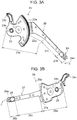
Figs. 3A and 3B are perspective views showing a pair of drive arms provided in the in-vehicle electronic device of the embodiment shown inFig. 1 ; and -
Fig. 4A is a plan view of the first drive arm, andFig. 4B is a front view thereof. -
Fig. 1 is a perspective view showing a state in which adisplay 12 serving as a device main body is lowered and in a retracted position in an in-vehicleelectronic device 1 according to an embodiment of the present invention.Fig. 2 is a front view showing a state in which thedisplay 12 projects upward and is in a display position in the in-vehicleelectronic device 1. - As shown in
Fig. 1 , the in-vehicleelectronic device 1 has afixed frame 3. Acover member 4 is fixed to the upper part of thefixed frame 3. A front frame (not shown) is fixed to the front side in the figure of thefixed frame 3 shown inFig. 1 . Thefixed frame 3, the front frame and thecover member 4 constitute a fixed portion 2. Thefixed frame 3, the front frame and thecover member 4 are all made of synthetic resin. Alternatively, only thecover member 4 is made of a metal plate. - The in-vehicle
electronic device 1 is installed in an instrument panel, a center console, or the like in a vehicle interior of an automobile. Thefixed frame 3 and the front frame are fixed inside the instrument panel or the center console, and thecover member 4 is fixed in the vicinity of the upper surface of the instrument panel or the center console.Fig. 1 shows a retracted position in which the movingmember 10 and thedisplay 12 serving as a device main body are lowered in the Z1 direction, and thedisplay 12 is hidden inside the housing of the instrument panel or the center console.Fig. 2 shows a display position (or use position) in which the movingmember 10 and thedisplay 12 are raised, and thedisplay 12 projects upward (in the Z2 direction) from the upper surface of the instrument panel or the center console. - A
first guide portion 5 and asecond guide portion 6 are fixed to thefixed frame 3. Thefirst guide portion 5 and thesecond guide portion 6 are guide shafts made of metal and having a circular cross section. Thefirst guide portion 5 and thesecond guide portion 6 are parallel to each other and extend linearly in the vertical direction (Z1-Z2 direction), and their upper ends and lower ends are fixed to thefixed frame 3. - The in-vehicle
electronic device 1 is provided with a moving member (lifting member) 10. The movingmember 10 is made of synthetic resin, a first bearingportion 11a and a second bearingportion 11b are formed vertically spaced apart from each other on the right side (Y1 side) in the figure, and a third bearingportion 11c is formed on the left side (Y2 side) in the figure. Sliding type thrust bearings are held by the bearingportions portion 11a and the second bearingportion 11b are slidably attached to thefirst guide portion 5, and the thrust bearing held by the third bearingportion 11c is slidably attached to thesecond guide portion 6. - The
display 12 as a device main body is mounted on the movingmember 10. Thedisplay 12 is a color liquid crystal display panel or an electroluminescence panel and has adisplay screen 13. As shown inFig. 2 , when thedisplay 12 serving as a device main body moves upward to the display position together with the movingmember 10, thedisplay screen 13 projects above the upper surface of the instrument panel or the center console, and thedisplay screen 13 can be visually observed in the vehicle interior. - As shown in
Fig. 1 , the in-vehicleelectronic device 1 is provided with adrive portion 20. Thedrive portion 20 has afirst drive arm 21 located on the Y2 side, asecond drive arm 26 located on the Y1 side, and adrive source 30 located above (Z2 direction) the drivearms fixed frame 3, and thefirst drive arm 21, thesecond drive arm 26, and thedrive source 30 are supported by the front frame. - As shown in
Figs. 3A ,4A, and 4B , thefirst drive arm 21 has anarm portion 22, agear portion 23, and a connectingportion 24. Thearm portion 22 is formed of a metal plate, and in the embodiment, it is formed of a stainless steel plate (SUS 304). Thegear portion 23 and the connectingportion 24 are made of synthetic resin, and thegear portion 23 and the connectingportion 24 are integrated with thearm portion 22 by a so-called insert molding method. - The
first drive arm 21 is roughly divided into aproximal portion 21a, adistal portion 21b, and anelastic portion 21c. Theelastic portion 21c is formed by thearm portion 22 made of a metal plate, and its width dimension is constant over its entire length. However, theelastic portion 21c may have such a shape that its width dimension gradually decreases toward the distal portion. Theproximal portion 21a is constituted by aproximal side portion 22a of thearm portion 22 and thegear portion 23. In thearm portion 22, the width dimension of theproximal side portion 22a is larger than the width dimension of thearm portion 22 in theelastic portion 21c. That is, in theproximal side portion 22a, the width dimension gradually increases toward thegear portion 23. - A
sector gear portion 23a and abearing hole 23b are formed in thegear portion 23. The pitch circle of thesector gear portion 23a coincides with an arc locus centered at thebearing hole 23b. Aspring hook portion 23c is integrally formed in thegear portion 23. A connectinghole 24a is integrally formed in the connectingportion 24 provided in thedistal portion 21b. - As shown in
Fig. 3B , also in thesecond drive arm 26, anarm portion 27 formed of a stainless steel plate (SUS 304), and agear portion 28 and a connectingportion 29 made of synthetic resin are integrated by a so-called insert molding method. Thesecond drive arm 26 is roughly divided into aproximal portion 26a, adistal portion 26b, and anelastic portion 26c. In theelastic portion 26c, the width dimension of thearm portion 27 is constant. Theproximal portion 26a is constituted by aproximal side portion 27a of thearm portion 27 and thegear portion 28, and the width dimension of theproximal side portion 27a is larger than the width dimension of thearm portion 27 in theelastic portion 26c. Thegear portion 28 has asector gear portion 28a, abearing hole 28b, and aspring hook portion 28c. A connectinghole 29a is formed in the connectingportion 29 made of synthetic resin integrated with thedistal portion 26b. - As shown in
Fig. 1 andFig. 2 ,rotation shafts frame 3. Thebearing hole 23b formed in thegear portion 23 of thefirst drive arm 21 is rotatably supported by therotation shaft 15, and thebearing hole 28b formed in thegear portion 28 of thesecond drive arm 26 is rotatably supported by therotation shaft 16. At this time, thesector gear portion 23a provided in theproximal portion 21a of thefirst drive arm 21 and thesector gear portion 28a provided in theproximal portion 26a of thesecond drive arm 26 are in mesh with each other. - As shown in
Figs. 1 and2 , the connectingportion 24 provided in thedistal portion 21b of thefirst drive arm 21 is connected to the Y1 side end of the movingmember 10 via alink member 17. A connectingshaft 17a provided at one end of thelink member 17 is rotatably inserted into the connectinghole 24a formed in the connectingportion 24 of thefirst drive arm 21. The other end of thelink member 17 and the Y1 side end of the movingmember 10 are rotatably connected via a supporting and connectingshaft 17b. - Similarly, the connecting
portion 29 provided in thedistal portion 26b of thesecond drive arm 26 is connected to the Y2 side end of the movingmember 10 via alink member 18. A connectingshaft 18a provided at one end of thelink member 18 is rotatably inserted into the connectinghole 29a formed in the connectingportion 29 of thesecond drive arm 26. The other end of thelink member 18 and the Y2 side end of the movingmember 10 are rotatably connected via a supporting and connectingshaft 18b. - In the present invention, it is not absolutely necessary to provide the
link members portion 24 of thefirst drive arm 21, the supporting and connectingshaft 17b provided in the movingmember 10 may be inserted into the elongated hole, and thefirst drive arm 21 and the movingmember 10 may be directly connected. Similarly, an elongated hole may formed in the connectingportion 29 of thedistal portion 26b of thesecond drive arm 26, the supporting and connectingshaft 18b may be inserted into the elongated hole, and thesecond drive arm 26 may be directly connected to the movingmember 10. - As shown in
Fig. 1 , thedrive source 30 has adrive bracket 31. Thedrive bracket 31 is fixed to the front frame (not shown). Adrive motor 32, areduction gear 33 and adrive gear 34 are supported by thedrive bracket 31. Aworm gear 35 is fixed to the output shaft of thedrive motor 32, the rotational output of thedrive motor 32 is decelerated by theworm gear 35 and thereduction gear 33, and thedrive gear 34 is driven. A pinion gear whose pitch circle is smaller than thedrive gear 34 is formed integrally with thedrive gear 34, and this pinion gear meshes with thesector gear portion 23a of thefirst drive arm 21. - As shown in
Fig. 2 , atension coil spring 19a is hooked between the front frame (not shown) and thespring hook portion 23c of thefirst drive arm 21, and atension coil spring 19b is hooked between the front frame and thespring hook portion 28c of thesecond drive arm 26. The urging force of thetension coil springs sector gear portion 23a and thesector gear portion 28a and the backlash between thesector gear portion 23a and the pinion gear. - As shown in
Fig. 1 , in the front frame (not shown), a retracted position detection switch SW1 and a display position detection switch SW2 are provided vertically spaced apart from each other. Adetection protrusion 11d is formed integrally with the movingmember 10, and the retracted position detection switch SW1 and the display position detection switch SW2 are caused to operate by thedetection protrusion 11d. - In the
first drive arm 21, thebearing hole 23b of thegear portion 23 is supported by therotation shaft 15 fixed to the front frame, and the connectingportion 24 of thedistal portion 21b is connected to the Y1 side end of the movingmember 10 via thelink member 17. At this time, thefirst drive arm 21 is attached in a state where the connectingportion 24 is displaced with respect to thegear portion 23 in the α direction shown inFig. 4A . Due to this displacement α, thearm portion 22 formed of a stainless steel plate is deflected in the plate thickness direction, and due to the elastic reaction force thereof, an urging force F1 directed toward the back side of the plane of the paper inFig. 2 is applied from the connectingportion 24 to the Y1 side end of the movingmember 10. The displacement α and the deflection direction of thearm portion 22 are parallel to the axial center line of therotation shaft 15 of thefirst drive arm 21 and are perpendicular to the direction in which thefirst guide portion 5 extends. Therefore, the urging force F1 is always constant even when the rotation angle of thefirst drive arm 21 is changed. - In the
arm portion 22 of thefirst drive arm 21, deflection occurs mainly in theelastic portion 21c having a small width dimension and small cross-sectional area, and the urging force F1 is applied to themovable member 10 due to this deflection. Although deflection also occurs in theproximal side portion 22a of thearm portion 22, since the width dimension and cross-sectional area of theproximal side portion 22a are larger than those of theelastic portion 21c, the deflection in theproximal side portion 22a is smaller than the deflection in theelastic portion 21c. In addition, since the width dimension of theproximal side portion 22a gradually increases toward thegear portion 23, the deflection and stress occurring in thearm portion 22 is less likely to be transmitted to thegear portion 23, and deformation or the like of thesector gear portion 23a can be suppressed. - Also in the
second drive arm 26, thebearing hole 28b of thegear portion 28 is supported by therotation shaft 16 fixed to the front frame, and the connectingportion 29 of thedistal portion 26b is connected to the Y2 side end of the movingmember 10 via thelink member 18. In a state where thesecond drive arm 26 is attached, the connectingportion 29 is displaced with respect to thegear portion 28 in the β direction shown inFig. 3B . Due to this displacement β, thearm portion 27 formed of a stainless steel plate is deflected in the plate thickness direction, and due to the elastic reaction force thereof, an urging force F2 directed toward the back side of the plane of the paper inFig. 2 is applied from the connectingportion 29 to the Y2 side end of the movingmember 10. - As shown in
Fig. 3B , in thearm portion 27 of thesecond drive arm 26, deflection occurs mainly in theelastic portion 26c having a small width dimension and small cross-sectional area, and the urging force F2 is applied to themovable member 10. Since the width dimension and cross-sectional area of theproximal side portion 27a of thearm portion 27 are large, the deflection in this portion is smaller than that of theelastic portion 26c. Therefore, the deflection and stress occurring in theelastic portion 26c is less likely to be transmitted to thegear portion 28, and deformation or the like of thesector gear portion 28a can be suppressed. - Next, the operation of the in-vehicle
electronic device 1 will be described. -
Fig. 1 shows the retracted position in which thedisplay 12 serving as a device main body is lowered. At this time, the retracted position detection switch SW1 is caused to operate by thedetection protrusion 11d provided at the Y1 side end the of the movingmember 10, and thedrive motor 32 is stopped based on the detection signal. - When an operation signal for setting the
display 12 to the display position is given to a control unit (not shown), a drive command is issued to a motor driver, and thedrive motor 32 is started. Its output is decelerated by theworm gear 35 and thereduction gear 33 and transmitted from the pinion gear integrated with thedrive gear 34 to thesector gear portion 23a of thefirst drive arm 21. Thefirst drive arm 21 rotates counterclockwise from the position ofFig. 1 , and thesecond drive arm 26 rotates clockwise due to engagement between thesector gear portion 23a and thesector gear portion 28a. The rotating force of thefirst drive arm 21 is transmitted to the movingmember 10 via thelink member 17, the rotating force of thesecond drive arm 26 is transmitted to the movingmember 10 via thelink member 18, and the movingmember 10 is lifted to the display position as shown inFig. 2 . When the display position detection switch SW2 is caused to operate by thedetection protrusion 11d provided in the movingmember 10, a stop command is given to the motor driver from the control unit. - When the moving
member 10 stops at the raised position shown inFig. 2 , thedisplay 12 projects upward from thecover member 4 and is in the display position in which thedisplay screen 13 is exposed. - When the moving
member 10 moves up and down while being guided by thefirst guide portion 5 and thesecond guide portion 6, due to the deflection mainly of theelastic portion 21c of thearm portion 22 of thefirst drive arm 21, the urging force F1 for pressing the Y1 side end of the movingmember 10 against thefirst guide portion 5 is given. Similarly, due to the deflection mainly of theelastic portion 26c of thearm portion 27 of thesecond drive arm 26, the urging force F2 for pressing the Y2 side end of the movingmember 10 against thesecond guide portion 6 is given. - Therefore, the
first bearing portion 11a and thesecond bearing portion 11b of the movingmember 10 stably abut on and slide on thefirst guide portion 5, and thethird bearing portion 11c stably abuts on and slides on thesecond guide portion 6. As a result, occurrence of stick-slip when the movingmember 10 moves up and down can be prevented, and the movingmember 10 can be smoothly raised and lowered. In addition, rattling due to the clearance between the bearingportions member 10 and theguide portions - Since the in-vehicle
electronic device 1 is not provided with spring members only for the purpose of restricting rattling between the movingmember 10 and theguide portions - Since the
elastic portion 21c of thearm portion 22 of thefirst drive arm 21 and theelastic portion 26c of thearm portion 26 of thesecond drive arm 26 can be formed long, even if the spring constants of thearm portions - Although, in the above embodiment, the device main body supported by the moving
member 10 is a display, the device main body may be other than adisplay 12, for example, a disk tray, a recording medium attachment portion therefor, or a tray on which a glass is placed.
Claims (7)
- An in-vehicle electronic device (1) comprising: at least one guide portion (5, 6) provided in a fixed portion (2); a moving member (10) reciprocatably supported by the at least one guide portion (5, 6); a device main body (12) mounted on the moving member (10); and a drive portion (20) configured to reciprocate the moving member (10) along the at least one guide portion (5, 6),
characterized in that the drive portion (20) is provided with at least one drive arm (21, 26) supported rotatably about a rotation shaft (15, 16) located between the drive portion (20) and the fixed portion (2) and configured to apply reciprocating force to the moving member (10), and a drive source (30) configured to rotate the at least one drive arm (21, 26), and
the at least one drive arm (21, 26) has an elastic portion (21c, 26c), and the moving member (10) is urged against the at least one guide portion (5, 6) by elastic force exerted by the deflection of the elastic portion (21c, 26c) in the direction of the axial center line of the rotation shaft (15, 16). - The in-vehicle electronic device (1) according to claim 1, wherein the at least one guide portion (5, 6) comprises a pair of guide portions (5, 6), the at least one drive arm (21, 26) comprises a pair of drive arms (21, 26), the elastic portions (21c, 26c) are directed toward the respective drive arms (21, 26), and the moving member (10) is urged against the respective guide portions (5, 6) by the pair of drive arms (21, 26).
- The in-vehicle electronic device (1) according to claim 1 or 2, wherein at least part of the at least one drive arm (21, 26) is formed of a metal plate, at least part of the metal plate is the elastic portion (21c, 26c), and deflection is imparted to the elastic portion (21c, 26c).
- The in-vehicle electronic device (1) according to any one of claims 1 to 3, wherein the at least one drive arm (21, 26) has a proximal portion (21a, 26a) rotatably supported by the fixed portion (2), a distal portion (21b, 26b) connected to the moving member (10), and the elastic portion (21c, 26c) located between the proximal portion (21a, 26a) and the distal portion (21b, 26b), and the cross-sectional area of the proximal portion (21a, 26a) is larger than the cross-sectional area of the elastic portion (21c, 26c) .
- The in-vehicle electronic device (1) according to claim 4, wherein the at least one drive arm (21, 26) has an arm portion (22, 27) forming the elastic portion (21c, 26c) and made of a metal plate, and a gear portion (23, 28) integrated with the arm portion (22, 27) in the proximal portion (21a, 26a) and made of synthetic resin.
- The in-vehicle electronic device (1) according to claim 4 or 5, wherein the distal portion (21b, 26b) is connected via a link member (17, 18) or directly to the moving member (10).
- The in-vehicle electronic device (1) according to any one of claims 1 to 6, wherein the device main body (12) is a display, and the display (12) is moved between a non-display position and a display position by the reciprocating movement of the moving member (10).
Applications Claiming Priority (1)
| Application Number | Priority Date | Filing Date | Title |
|---|---|---|---|
| JP2017109643A JP6817148B2 (en) | 2017-06-02 | 2017-06-02 | In-vehicle electronic device |
Publications (2)
| Publication Number | Publication Date |
|---|---|
| EP3409527A1 true EP3409527A1 (en) | 2018-12-05 |
| EP3409527B1 EP3409527B1 (en) | 2020-04-08 |
Family
ID=62530095
Family Applications (1)
| Application Number | Title | Priority Date | Filing Date |
|---|---|---|---|
| EP18174866.6A Active EP3409527B1 (en) | 2017-06-02 | 2018-05-29 | In-vehicle electronic device |
Country Status (2)
| Country | Link |
|---|---|
| EP (1) | EP3409527B1 (en) |
| JP (1) | JP6817148B2 (en) |
Cited By (4)
| Publication number | Priority date | Publication date | Assignee | Title |
|---|---|---|---|---|
| CN113085740A (en) * | 2020-01-08 | 2021-07-09 | Lg电子株式会社 | Vehicle-mounted display device |
| CN113183887A (en) * | 2021-04-30 | 2021-07-30 | 重庆长安新能源汽车科技有限公司 | Central control display screen assembly |
| CN113246872A (en) * | 2021-06-30 | 2021-08-13 | 重庆长安新能源汽车科技有限公司 | Vehicle-mounted display system and vehicle |
| EP4501711A4 (en) * | 2022-04-29 | 2025-07-16 | Shenzhen Yinwang Intelligent Technology Co Ltd | OPTICAL DISPLAY, SEAT AND VEHICLE |
Citations (5)
| Publication number | Priority date | Publication date | Assignee | Title |
|---|---|---|---|---|
| DE102012008575A1 (en) * | 2012-04-27 | 2013-10-31 | Brose Fahrzeugteile Gmbh & Co. Kommanditgesellschaft, Coburg | Image screen adjustment device for motor car, has two linear guide elements which are connected to other two linear guide elements and cooperated at specific side end portions of control levers |
| WO2013189610A2 (en) | 2012-06-23 | 2013-12-27 | Brose Fahrzeugteile Gmbh & Co. Kommanditgesellschaft, Coburg | Screen adjustment device for a motor vehicle |
| EP2712767A1 (en) * | 2012-09-27 | 2014-04-02 | Alpine Electronics, Inc. | On-vehicle electronic device |
| JP2015225174A (en) * | 2014-05-27 | 2015-12-14 | アルパイン株式会社 | On-vehicle electronic device |
| EP2955563A1 (en) * | 2014-06-11 | 2015-12-16 | Jabil Circuit, Inc. | Head-up display system with a drive mechanism to move a combiner |
-
2017
- 2017-06-02 JP JP2017109643A patent/JP6817148B2/en active Active
-
2018
- 2018-05-29 EP EP18174866.6A patent/EP3409527B1/en active Active
Patent Citations (5)
| Publication number | Priority date | Publication date | Assignee | Title |
|---|---|---|---|---|
| DE102012008575A1 (en) * | 2012-04-27 | 2013-10-31 | Brose Fahrzeugteile Gmbh & Co. Kommanditgesellschaft, Coburg | Image screen adjustment device for motor car, has two linear guide elements which are connected to other two linear guide elements and cooperated at specific side end portions of control levers |
| WO2013189610A2 (en) | 2012-06-23 | 2013-12-27 | Brose Fahrzeugteile Gmbh & Co. Kommanditgesellschaft, Coburg | Screen adjustment device for a motor vehicle |
| EP2712767A1 (en) * | 2012-09-27 | 2014-04-02 | Alpine Electronics, Inc. | On-vehicle electronic device |
| JP2015225174A (en) * | 2014-05-27 | 2015-12-14 | アルパイン株式会社 | On-vehicle electronic device |
| EP2955563A1 (en) * | 2014-06-11 | 2015-12-16 | Jabil Circuit, Inc. | Head-up display system with a drive mechanism to move a combiner |
Cited By (8)
| Publication number | Priority date | Publication date | Assignee | Title |
|---|---|---|---|---|
| CN113085740A (en) * | 2020-01-08 | 2021-07-09 | Lg电子株式会社 | Vehicle-mounted display device |
| EP3848224A1 (en) * | 2020-01-08 | 2021-07-14 | LG Electronics Inc. | Display apparatus for vehicle |
| US11178782B2 (en) | 2020-01-08 | 2021-11-16 | Lg Electronics Inc. | Display apparatus for vehicle |
| CN113085740B (en) * | 2020-01-08 | 2023-05-02 | Lg电子株式会社 | Vehicle-mounted display device |
| CN113183887A (en) * | 2021-04-30 | 2021-07-30 | 重庆长安新能源汽车科技有限公司 | Central control display screen assembly |
| CN113183887B (en) * | 2021-04-30 | 2022-08-02 | 重庆长安新能源汽车科技有限公司 | Central control display screen assembly |
| CN113246872A (en) * | 2021-06-30 | 2021-08-13 | 重庆长安新能源汽车科技有限公司 | Vehicle-mounted display system and vehicle |
| EP4501711A4 (en) * | 2022-04-29 | 2025-07-16 | Shenzhen Yinwang Intelligent Technology Co Ltd | OPTICAL DISPLAY, SEAT AND VEHICLE |
Also Published As
| Publication number | Publication date |
|---|---|
| JP6817148B2 (en) | 2021-01-20 |
| EP3409527B1 (en) | 2020-04-08 |
| JP2018202992A (en) | 2018-12-27 |
Similar Documents
| Publication | Publication Date | Title |
|---|---|---|
| EP3409527B1 (en) | In-vehicle electronic device | |
| KR101188033B1 (en) | Head-up display device | |
| US8002179B2 (en) | Hidden console display | |
| US9010268B2 (en) | Vehicle display apparatus | |
| JP5301586B2 (en) | Head-up display combiner localization system | |
| EP2712767B1 (en) | On-vehicle electronic device | |
| US9003910B2 (en) | Instrumental unit | |
| US8081387B2 (en) | Display device | |
| JP5877558B2 (en) | Head-up display device | |
| US9796250B2 (en) | Vehicle window regulator, and vehicle door structure comprising the vehicle window regulator | |
| CN107000650B (en) | For opening and closing at the component of the opening in vehicle interior part | |
| JP2009291290A (en) | Movable decoration device of game machine | |
| EP1118741A2 (en) | Rolling contact screw-and-nut transmission device, and linear actuator comprising this device | |
| JP6808291B2 (en) | Head-up display device | |
| JP2019203528A (en) | Guide drive device and display device using guide drive device | |
| JP2014080808A (en) | Automatic opening/closing device for vehicle | |
| US20090056617A1 (en) | Indicator Apparatus | |
| EP4389490A1 (en) | Display device | |
| CN217396396U (en) | Vehicle-mounted display device | |
| CN110622052B (en) | Driving device for head-up display | |
| CN223882102U (en) | Electric adjustment bracket for electronic equipment | |
| KR102953106B1 (en) | A Car Pop-up Monitor Assembly | |
| JP2022062069A (en) | Display device using guide drive unit | |
| JP5930936B2 (en) | Automotive electronics | |
| EP3223117B1 (en) | Operation device and method for manufacturing the same |
Legal Events
| Date | Code | Title | Description |
|---|---|---|---|
| PUAI | Public reference made under article 153(3) epc to a published international application that has entered the european phase |
Free format text: ORIGINAL CODE: 0009012 |
|
| STAA | Information on the status of an ep patent application or granted ep patent |
Free format text: STATUS: THE APPLICATION HAS BEEN PUBLISHED |
|
| AK | Designated contracting states |
Kind code of ref document: A1 Designated state(s): AL AT BE BG CH CY CZ DE DK EE ES FI FR GB GR HR HU IE IS IT LI LT LU LV MC MK MT NL NO PL PT RO RS SE SI SK SM TR |
|
| AX | Request for extension of the european patent |
Extension state: BA ME |
|
| STAA | Information on the status of an ep patent application or granted ep patent |
Free format text: STATUS: REQUEST FOR EXAMINATION WAS MADE |
|
| 17P | Request for examination filed |
Effective date: 20190515 |
|
| RBV | Designated contracting states (corrected) |
Designated state(s): AL AT BE BG CH CY CZ DE DK EE ES FI FR GB GR HR HU IE IS IT LI LT LU LV MC MK MT NL NO PL PT RO RS SE SI SK SM TR |
|
| GRAP | Despatch of communication of intention to grant a patent |
Free format text: ORIGINAL CODE: EPIDOSNIGR1 |
|
| STAA | Information on the status of an ep patent application or granted ep patent |
Free format text: STATUS: GRANT OF PATENT IS INTENDED |
|
| INTG | Intention to grant announced |
Effective date: 20191115 |
|
| GRAS | Grant fee paid |
Free format text: ORIGINAL CODE: EPIDOSNIGR3 |
|
| GRAA | (expected) grant |
Free format text: ORIGINAL CODE: 0009210 |
|
| STAA | Information on the status of an ep patent application or granted ep patent |
Free format text: STATUS: THE PATENT HAS BEEN GRANTED |
|
| AK | Designated contracting states |
Kind code of ref document: B1 Designated state(s): AL AT BE BG CH CY CZ DE DK EE ES FI FR GB GR HR HU IE IS IT LI LT LU LV MC MK MT NL NO PL PT RO RS SE SI SK SM TR |
|
| REG | Reference to a national code |
Ref country code: CH Ref legal event code: EP Ref country code: AT Ref legal event code: REF Ref document number: 1253916 Country of ref document: AT Kind code of ref document: T Effective date: 20200415 |
|
| REG | Reference to a national code |
Ref country code: DE Ref legal event code: R096 Ref document number: 602018003547 Country of ref document: DE |
|
| REG | Reference to a national code |
Ref country code: IE Ref legal event code: FG4D |
|
| REG | Reference to a national code |
Ref country code: NL Ref legal event code: MP Effective date: 20200408 |
|
| REG | Reference to a national code |
Ref country code: LT Ref legal event code: MG4D |
|
| PG25 | Lapsed in a contracting state [announced via postgrant information from national office to epo] |
Ref country code: NL Free format text: LAPSE BECAUSE OF FAILURE TO SUBMIT A TRANSLATION OF THE DESCRIPTION OR TO PAY THE FEE WITHIN THE PRESCRIBED TIME-LIMIT Effective date: 20200408 Ref country code: SE Free format text: LAPSE BECAUSE OF FAILURE TO SUBMIT A TRANSLATION OF THE DESCRIPTION OR TO PAY THE FEE WITHIN THE PRESCRIBED TIME-LIMIT Effective date: 20200408 Ref country code: LT Free format text: LAPSE BECAUSE OF FAILURE TO SUBMIT A TRANSLATION OF THE DESCRIPTION OR TO PAY THE FEE WITHIN THE PRESCRIBED TIME-LIMIT Effective date: 20200408 Ref country code: IS Free format text: LAPSE BECAUSE OF FAILURE TO SUBMIT A TRANSLATION OF THE DESCRIPTION OR TO PAY THE FEE WITHIN THE PRESCRIBED TIME-LIMIT Effective date: 20200808 Ref country code: PT Free format text: LAPSE BECAUSE OF FAILURE TO SUBMIT A TRANSLATION OF THE DESCRIPTION OR TO PAY THE FEE WITHIN THE PRESCRIBED TIME-LIMIT Effective date: 20200817 Ref country code: FI Free format text: LAPSE BECAUSE OF FAILURE TO SUBMIT A TRANSLATION OF THE DESCRIPTION OR TO PAY THE FEE WITHIN THE PRESCRIBED TIME-LIMIT Effective date: 20200408 Ref country code: NO Free format text: LAPSE BECAUSE OF FAILURE TO SUBMIT A TRANSLATION OF THE DESCRIPTION OR TO PAY THE FEE WITHIN THE PRESCRIBED TIME-LIMIT Effective date: 20200708 Ref country code: GR Free format text: LAPSE BECAUSE OF FAILURE TO SUBMIT A TRANSLATION OF THE DESCRIPTION OR TO PAY THE FEE WITHIN THE PRESCRIBED TIME-LIMIT Effective date: 20200709 |
|
| REG | Reference to a national code |
Ref country code: AT Ref legal event code: MK05 Ref document number: 1253916 Country of ref document: AT Kind code of ref document: T Effective date: 20200408 |
|
| PG25 | Lapsed in a contracting state [announced via postgrant information from national office to epo] |
Ref country code: LV Free format text: LAPSE BECAUSE OF FAILURE TO SUBMIT A TRANSLATION OF THE DESCRIPTION OR TO PAY THE FEE WITHIN THE PRESCRIBED TIME-LIMIT Effective date: 20200408 Ref country code: RS Free format text: LAPSE BECAUSE OF FAILURE TO SUBMIT A TRANSLATION OF THE DESCRIPTION OR TO PAY THE FEE WITHIN THE PRESCRIBED TIME-LIMIT Effective date: 20200408 Ref country code: BG Free format text: LAPSE BECAUSE OF FAILURE TO SUBMIT A TRANSLATION OF THE DESCRIPTION OR TO PAY THE FEE WITHIN THE PRESCRIBED TIME-LIMIT Effective date: 20200708 Ref country code: HR Free format text: LAPSE BECAUSE OF FAILURE TO SUBMIT A TRANSLATION OF THE DESCRIPTION OR TO PAY THE FEE WITHIN THE PRESCRIBED TIME-LIMIT Effective date: 20200408 |
|
| PG25 | Lapsed in a contracting state [announced via postgrant information from national office to epo] |
Ref country code: AL Free format text: LAPSE BECAUSE OF FAILURE TO SUBMIT A TRANSLATION OF THE DESCRIPTION OR TO PAY THE FEE WITHIN THE PRESCRIBED TIME-LIMIT Effective date: 20200408 |
|
| REG | Reference to a national code |
Ref country code: DE Ref legal event code: R097 Ref document number: 602018003547 Country of ref document: DE |
|
| PG25 | Lapsed in a contracting state [announced via postgrant information from national office to epo] |
Ref country code: RO Free format text: LAPSE BECAUSE OF FAILURE TO SUBMIT A TRANSLATION OF THE DESCRIPTION OR TO PAY THE FEE WITHIN THE PRESCRIBED TIME-LIMIT Effective date: 20200408 Ref country code: IT Free format text: LAPSE BECAUSE OF FAILURE TO SUBMIT A TRANSLATION OF THE DESCRIPTION OR TO PAY THE FEE WITHIN THE PRESCRIBED TIME-LIMIT Effective date: 20200408 Ref country code: CZ Free format text: LAPSE BECAUSE OF FAILURE TO SUBMIT A TRANSLATION OF THE DESCRIPTION OR TO PAY THE FEE WITHIN THE PRESCRIBED TIME-LIMIT Effective date: 20200408 Ref country code: ES Free format text: LAPSE BECAUSE OF FAILURE TO SUBMIT A TRANSLATION OF THE DESCRIPTION OR TO PAY THE FEE WITHIN THE PRESCRIBED TIME-LIMIT Effective date: 20200408 Ref country code: SM Free format text: LAPSE BECAUSE OF FAILURE TO SUBMIT A TRANSLATION OF THE DESCRIPTION OR TO PAY THE FEE WITHIN THE PRESCRIBED TIME-LIMIT Effective date: 20200408 Ref country code: EE Free format text: LAPSE BECAUSE OF FAILURE TO SUBMIT A TRANSLATION OF THE DESCRIPTION OR TO PAY THE FEE WITHIN THE PRESCRIBED TIME-LIMIT Effective date: 20200408 Ref country code: AT Free format text: LAPSE BECAUSE OF FAILURE TO SUBMIT A TRANSLATION OF THE DESCRIPTION OR TO PAY THE FEE WITHIN THE PRESCRIBED TIME-LIMIT Effective date: 20200408 Ref country code: DK Free format text: LAPSE BECAUSE OF FAILURE TO SUBMIT A TRANSLATION OF THE DESCRIPTION OR TO PAY THE FEE WITHIN THE PRESCRIBED TIME-LIMIT Effective date: 20200408 Ref country code: MC Free format text: LAPSE BECAUSE OF FAILURE TO SUBMIT A TRANSLATION OF THE DESCRIPTION OR TO PAY THE FEE WITHIN THE PRESCRIBED TIME-LIMIT Effective date: 20200408 |
|
| PLBE | No opposition filed within time limit |
Free format text: ORIGINAL CODE: 0009261 |
|
| STAA | Information on the status of an ep patent application or granted ep patent |
Free format text: STATUS: NO OPPOSITION FILED WITHIN TIME LIMIT |
|
| PG25 | Lapsed in a contracting state [announced via postgrant information from national office to epo] |
Ref country code: SK Free format text: LAPSE BECAUSE OF FAILURE TO SUBMIT A TRANSLATION OF THE DESCRIPTION OR TO PAY THE FEE WITHIN THE PRESCRIBED TIME-LIMIT Effective date: 20200408 Ref country code: PL Free format text: LAPSE BECAUSE OF FAILURE TO SUBMIT A TRANSLATION OF THE DESCRIPTION OR TO PAY THE FEE WITHIN THE PRESCRIBED TIME-LIMIT Effective date: 20200408 |
|
| 26N | No opposition filed |
Effective date: 20210112 |
|
| REG | Reference to a national code |
Ref country code: BE Ref legal event code: MM Effective date: 20200531 |
|
| PG25 | Lapsed in a contracting state [announced via postgrant information from national office to epo] |
Ref country code: LU Free format text: LAPSE BECAUSE OF NON-PAYMENT OF DUE FEES Effective date: 20200529 |
|
| PG25 | Lapsed in a contracting state [announced via postgrant information from national office to epo] |
Ref country code: IE Free format text: LAPSE BECAUSE OF NON-PAYMENT OF DUE FEES Effective date: 20200529 |
|
| PG25 | Lapsed in a contracting state [announced via postgrant information from national office to epo] |
Ref country code: BE Free format text: LAPSE BECAUSE OF NON-PAYMENT OF DUE FEES Effective date: 20200531 Ref country code: SI Free format text: LAPSE BECAUSE OF FAILURE TO SUBMIT A TRANSLATION OF THE DESCRIPTION OR TO PAY THE FEE WITHIN THE PRESCRIBED TIME-LIMIT Effective date: 20200408 |
|
| REG | Reference to a national code |
Ref country code: CH Ref legal event code: PL |
|
| PG25 | Lapsed in a contracting state [announced via postgrant information from national office to epo] |
Ref country code: LI Free format text: LAPSE BECAUSE OF NON-PAYMENT OF DUE FEES Effective date: 20210531 Ref country code: CH Free format text: LAPSE BECAUSE OF NON-PAYMENT OF DUE FEES Effective date: 20210531 |
|
| PG25 | Lapsed in a contracting state [announced via postgrant information from national office to epo] |
Ref country code: TR Free format text: LAPSE BECAUSE OF FAILURE TO SUBMIT A TRANSLATION OF THE DESCRIPTION OR TO PAY THE FEE WITHIN THE PRESCRIBED TIME-LIMIT Effective date: 20200408 Ref country code: MT Free format text: LAPSE BECAUSE OF FAILURE TO SUBMIT A TRANSLATION OF THE DESCRIPTION OR TO PAY THE FEE WITHIN THE PRESCRIBED TIME-LIMIT Effective date: 20200408 Ref country code: CY Free format text: LAPSE BECAUSE OF FAILURE TO SUBMIT A TRANSLATION OF THE DESCRIPTION OR TO PAY THE FEE WITHIN THE PRESCRIBED TIME-LIMIT Effective date: 20200408 |
|
| PG25 | Lapsed in a contracting state [announced via postgrant information from national office to epo] |
Ref country code: MK Free format text: LAPSE BECAUSE OF FAILURE TO SUBMIT A TRANSLATION OF THE DESCRIPTION OR TO PAY THE FEE WITHIN THE PRESCRIBED TIME-LIMIT Effective date: 20200408 |
|
| PGFP | Annual fee paid to national office [announced via postgrant information from national office to epo] |
Ref country code: DE Payment date: 20250521 Year of fee payment: 8 |
|
| PGFP | Annual fee paid to national office [announced via postgrant information from national office to epo] |
Ref country code: GB Payment date: 20250527 Year of fee payment: 8 |
|
| PGFP | Annual fee paid to national office [announced via postgrant information from national office to epo] |
Ref country code: FR Payment date: 20250528 Year of fee payment: 8 |