EP3409525A1 - User interface apparatus for vehicle and vehicle - Google Patents
User interface apparatus for vehicle and vehicle Download PDFInfo
- Publication number
- EP3409525A1 EP3409525A1 EP18164176.2A EP18164176A EP3409525A1 EP 3409525 A1 EP3409525 A1 EP 3409525A1 EP 18164176 A EP18164176 A EP 18164176A EP 3409525 A1 EP3409525 A1 EP 3409525A1
- Authority
- EP
- European Patent Office
- Prior art keywords
- information
- processor
- planning
- vehicle
- driving
- Prior art date
- Legal status (The legal status is an assumption and is not a legal conclusion. Google has not performed a legal analysis and makes no representation as to the accuracy of the status listed.)
- Granted
Links
- 230000000694 effects Effects 0.000 claims abstract description 17
- 235000012489 doughnuts Nutrition 0.000 claims description 56
- 238000004891 communication Methods 0.000 description 48
- 238000001514 detection method Methods 0.000 description 28
- 230000005540 biological transmission Effects 0.000 description 23
- 238000010586 diagram Methods 0.000 description 14
- 230000008859 change Effects 0.000 description 8
- 238000005192 partition Methods 0.000 description 8
- 230000007704 transition Effects 0.000 description 8
- 230000033001 locomotion Effects 0.000 description 7
- 230000003287 optical effect Effects 0.000 description 7
- 239000000725 suspension Substances 0.000 description 7
- 230000001133 acceleration Effects 0.000 description 6
- 239000000470 constituent Substances 0.000 description 5
- 238000012986 modification Methods 0.000 description 4
- 230000004048 modification Effects 0.000 description 4
- 238000012545 processing Methods 0.000 description 4
- 239000000446 fuel Substances 0.000 description 3
- 239000004973 liquid crystal related substance Substances 0.000 description 3
- 238000005259 measurement Methods 0.000 description 3
- 230000010363 phase shift Effects 0.000 description 3
- 230000004044 response Effects 0.000 description 3
- 238000013459 approach Methods 0.000 description 2
- 230000006870 function Effects 0.000 description 2
- 238000005286 illumination Methods 0.000 description 2
- 238000007726 management method Methods 0.000 description 2
- 230000005236 sound signal Effects 0.000 description 2
- 239000010409 thin film Substances 0.000 description 2
- 230000000007 visual effect Effects 0.000 description 2
- XUIMIQQOPSSXEZ-UHFFFAOYSA-N Silicon Chemical compound [Si] XUIMIQQOPSSXEZ-UHFFFAOYSA-N 0.000 description 1
- 238000003491 array Methods 0.000 description 1
- 230000008901 benefit Effects 0.000 description 1
- 238000002485 combustion reaction Methods 0.000 description 1
- 238000013500 data storage Methods 0.000 description 1
- 230000001419 dependent effect Effects 0.000 description 1
- 210000003195 fascia Anatomy 0.000 description 1
- 239000002803 fossil fuel Substances 0.000 description 1
- 239000011521 glass Substances 0.000 description 1
- 239000011229 interlayer Substances 0.000 description 1
- 238000000034 method Methods 0.000 description 1
- 238000012544 monitoring process Methods 0.000 description 1
- 230000007935 neutral effect Effects 0.000 description 1
- 238000002360 preparation method Methods 0.000 description 1
- 229910052710 silicon Inorganic materials 0.000 description 1
- 239000010703 silicon Substances 0.000 description 1
- 239000007787 solid Substances 0.000 description 1
- 238000006467 substitution reaction Methods 0.000 description 1
- 238000012546 transfer Methods 0.000 description 1
- XLYOFNOQVPJJNP-UHFFFAOYSA-N water Substances O XLYOFNOQVPJJNP-UHFFFAOYSA-N 0.000 description 1
Images


Classifications
-
- B—PERFORMING OPERATIONS; TRANSPORTING
- B60—VEHICLES IN GENERAL
- B60W—CONJOINT CONTROL OF VEHICLE SUB-UNITS OF DIFFERENT TYPE OR DIFFERENT FUNCTION; CONTROL SYSTEMS SPECIALLY ADAPTED FOR HYBRID VEHICLES; ROAD VEHICLE DRIVE CONTROL SYSTEMS FOR PURPOSES NOT RELATED TO THE CONTROL OF A PARTICULAR SUB-UNIT
- B60W50/00—Details of control systems for road vehicle drive control not related to the control of a particular sub-unit, e.g. process diagnostic or vehicle driver interfaces
- B60W50/08—Interaction between the driver and the control system
- B60W50/14—Means for informing the driver, warning the driver or prompting a driver intervention
-
- B—PERFORMING OPERATIONS; TRANSPORTING
- B60—VEHICLES IN GENERAL
- B60Q—ARRANGEMENT OF SIGNALLING OR LIGHTING DEVICES, THE MOUNTING OR SUPPORTING THEREOF OR CIRCUITS THEREFOR, FOR VEHICLES IN GENERAL
- B60Q9/00—Arrangement or adaptation of signal devices not provided for in one of main groups B60Q1/00 - B60Q7/00, e.g. haptic signalling
- B60Q9/002—Arrangement or adaptation of signal devices not provided for in one of main groups B60Q1/00 - B60Q7/00, e.g. haptic signalling for parking purposes, e.g. for warning the driver that his vehicle has contacted or is about to contact an obstacle
-
- B—PERFORMING OPERATIONS; TRANSPORTING
- B60—VEHICLES IN GENERAL
- B60K—ARRANGEMENT OR MOUNTING OF PROPULSION UNITS OR OF TRANSMISSIONS IN VEHICLES; ARRANGEMENT OR MOUNTING OF PLURAL DIVERSE PRIME-MOVERS IN VEHICLES; AUXILIARY DRIVES FOR VEHICLES; INSTRUMENTATION OR DASHBOARDS FOR VEHICLES; ARRANGEMENTS IN CONNECTION WITH COOLING, AIR INTAKE, GAS EXHAUST OR FUEL SUPPLY OF PROPULSION UNITS IN VEHICLES
- B60K35/00—Arrangement of adaptations of instruments
-
- B60K35/22—
-
- B60K35/28—
-
- B—PERFORMING OPERATIONS; TRANSPORTING
- B60—VEHICLES IN GENERAL
- B60W—CONJOINT CONTROL OF VEHICLE SUB-UNITS OF DIFFERENT TYPE OR DIFFERENT FUNCTION; CONTROL SYSTEMS SPECIALLY ADAPTED FOR HYBRID VEHICLES; ROAD VEHICLE DRIVE CONTROL SYSTEMS FOR PURPOSES NOT RELATED TO THE CONTROL OF A PARTICULAR SUB-UNIT
- B60W10/00—Conjoint control of vehicle sub-units of different type or different function
- B60W10/20—Conjoint control of vehicle sub-units of different type or different function including control of steering systems
-
- B—PERFORMING OPERATIONS; TRANSPORTING
- B60—VEHICLES IN GENERAL
- B60W—CONJOINT CONTROL OF VEHICLE SUB-UNITS OF DIFFERENT TYPE OR DIFFERENT FUNCTION; CONTROL SYSTEMS SPECIALLY ADAPTED FOR HYBRID VEHICLES; ROAD VEHICLE DRIVE CONTROL SYSTEMS FOR PURPOSES NOT RELATED TO THE CONTROL OF A PARTICULAR SUB-UNIT
- B60W30/00—Purposes of road vehicle drive control systems not related to the control of a particular sub-unit, e.g. of systems using conjoint control of vehicle sub-units, or advanced driver assistance systems for ensuring comfort, stability and safety or drive control systems for propelling or retarding the vehicle
- B60W30/06—Automatic manoeuvring for parking
-
- B—PERFORMING OPERATIONS; TRANSPORTING
- B60—VEHICLES IN GENERAL
- B60W—CONJOINT CONTROL OF VEHICLE SUB-UNITS OF DIFFERENT TYPE OR DIFFERENT FUNCTION; CONTROL SYSTEMS SPECIALLY ADAPTED FOR HYBRID VEHICLES; ROAD VEHICLE DRIVE CONTROL SYSTEMS FOR PURPOSES NOT RELATED TO THE CONTROL OF A PARTICULAR SUB-UNIT
- B60W40/00—Estimation or calculation of non-directly measurable driving parameters for road vehicle drive control systems not related to the control of a particular sub unit, e.g. by using mathematical models
- B60W40/02—Estimation or calculation of non-directly measurable driving parameters for road vehicle drive control systems not related to the control of a particular sub unit, e.g. by using mathematical models related to ambient conditions
-
- B—PERFORMING OPERATIONS; TRANSPORTING
- B60—VEHICLES IN GENERAL
- B60W—CONJOINT CONTROL OF VEHICLE SUB-UNITS OF DIFFERENT TYPE OR DIFFERENT FUNCTION; CONTROL SYSTEMS SPECIALLY ADAPTED FOR HYBRID VEHICLES; ROAD VEHICLE DRIVE CONTROL SYSTEMS FOR PURPOSES NOT RELATED TO THE CONTROL OF A PARTICULAR SUB-UNIT
- B60W40/00—Estimation or calculation of non-directly measurable driving parameters for road vehicle drive control systems not related to the control of a particular sub unit, e.g. by using mathematical models
- B60W40/10—Estimation or calculation of non-directly measurable driving parameters for road vehicle drive control systems not related to the control of a particular sub unit, e.g. by using mathematical models related to vehicle motion
- B60W40/105—Speed
-
- B—PERFORMING OPERATIONS; TRANSPORTING
- B62—LAND VEHICLES FOR TRAVELLING OTHERWISE THAN ON RAILS
- B62D—MOTOR VEHICLES; TRAILERS
- B62D15/00—Steering not otherwise provided for
- B62D15/02—Steering position indicators ; Steering position determination; Steering aids
- B62D15/027—Parking aids, e.g. instruction means
- B62D15/0285—Parking performed automatically
-
- G—PHYSICS
- G06—COMPUTING; CALCULATING OR COUNTING
- G06T—IMAGE DATA PROCESSING OR GENERATION, IN GENERAL
- G06T13/00—Animation
- G06T13/80—2D [Two Dimensional] animation, e.g. using sprites
-
- G—PHYSICS
- G08—SIGNALLING
- G08G—TRAFFIC CONTROL SYSTEMS
- G08G1/00—Traffic control systems for road vehicles
- G08G1/16—Anti-collision systems
- G08G1/168—Driving aids for parking, e.g. acoustic or visual feedback on parking space
-
- G—PHYSICS
- G09—EDUCATION; CRYPTOGRAPHY; DISPLAY; ADVERTISING; SEALS
- G09G—ARRANGEMENTS OR CIRCUITS FOR CONTROL OF INDICATING DEVICES USING STATIC MEANS TO PRESENT VARIABLE INFORMATION
- G09G5/00—Control arrangements or circuits for visual indicators common to cathode-ray tube indicators and other visual indicators
- G09G5/36—Control arrangements or circuits for visual indicators common to cathode-ray tube indicators and other visual indicators characterised by the display of a graphic pattern, e.g. using an all-points-addressable [APA] memory
- G09G5/37—Details of the operation on graphic patterns
-
- B60K2360/166—
-
- B60K2360/167—
-
- B60K2360/171—
-
- B60K2360/172—
-
- B60K2360/173—
-
- B60K2360/175—
-
- B60K2360/179—
-
- B—PERFORMING OPERATIONS; TRANSPORTING
- B60—VEHICLES IN GENERAL
- B60W—CONJOINT CONTROL OF VEHICLE SUB-UNITS OF DIFFERENT TYPE OR DIFFERENT FUNCTION; CONTROL SYSTEMS SPECIALLY ADAPTED FOR HYBRID VEHICLES; ROAD VEHICLE DRIVE CONTROL SYSTEMS FOR PURPOSES NOT RELATED TO THE CONTROL OF A PARTICULAR SUB-UNIT
- B60W50/00—Details of control systems for road vehicle drive control not related to the control of a particular sub-unit, e.g. process diagnostic or vehicle driver interfaces
- B60W50/08—Interaction between the driver and the control system
- B60W50/14—Means for informing the driver, warning the driver or prompting a driver intervention
- B60W2050/146—Display means
-
- B—PERFORMING OPERATIONS; TRANSPORTING
- B60—VEHICLES IN GENERAL
- B60Y—INDEXING SCHEME RELATING TO ASPECTS CROSS-CUTTING VEHICLE TECHNOLOGY
- B60Y2300/00—Purposes or special features of road vehicle drive control systems
- B60Y2300/06—Automatic manoeuvring for parking
-
- B—PERFORMING OPERATIONS; TRANSPORTING
- B60—VEHICLES IN GENERAL
- B60Y—INDEXING SCHEME RELATING TO ASPECTS CROSS-CUTTING VEHICLE TECHNOLOGY
- B60Y2400/00—Special features of vehicle units
- B60Y2400/92—Driver displays
-
- G—PHYSICS
- G09—EDUCATION; CRYPTOGRAPHY; DISPLAY; ADVERTISING; SEALS
- G09G—ARRANGEMENTS OR CIRCUITS FOR CONTROL OF INDICATING DEVICES USING STATIC MEANS TO PRESENT VARIABLE INFORMATION
- G09G2380/00—Specific applications
- G09G2380/10—Automotive applications
Definitions
- the present invention relates to a user interface apparatus for vehicle, and a vehicle.
- a vehicle is an apparatus that moves in a direction desired by a user riding therein.
- a representative example of a vehicle may be an automobile.
- the present invention has been made in view of the above problems, and it is one object of the present invention to provide a user interface apparatus for a vehicle, which provides information to a user so that the user in a vehicle capable of being automatically (or autonomously) parked is able to recognize a parking situation .
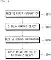
- a user interface apparatus for a vehicle, including: a display unit; an interface unit configured to receive first information about autonomous parking planning, and second information about a progress situation of an autonomous parking maneuver being performed based on the autonomous parking planning; and a processor configured to display a graphic object corresponding to the first information, and control the display unit based on the second information to apply an animation effect to the graphic object.
- the embodiments of the present invention have one or more effects as follows.
- the present invention also relates to a user interface apparatus for a vehicle comprising a display unit; an interface unit configured to receive first information about autonomous parking planning, and second information about a progress situation of an autonomous parking maneuver being performed based on the autonomous parking planning; and
- a processor configured to display a graphic object corresponding to the first information, and control the display unit based on the second information to apply an animation effect to the graphic object.
- the first information comprises at least one of turn-around planning information, forward driving planning information, reverse driving planning information, left-steering planning information, and right-steering planning information
- the second information comprises at least one of turn-around driving situation information, forward driving situation information, reverse driving situation information, left-steered driving situation information, and right-steered driving situation information.
- the first information comprises turn-around planning information and the second information comprises turn-around driving situation information.
- the first information comprises forward driving planning information and the second information comprises forward driving situation information.
- the first information comprises reverse driving planning information and the second information comprises reverse driving situation information.
- the first information comprises left-steering planning information and the second information comprises left-steered driving situation.
- the first information comprises right-steering planning information and the second information comprises right-steered driving situation information.
- the processor is further configured to display, based on the turn-around planning information, a figure which is divided into a plurality of sections and to control the display unit based on the second information so that at least one of a color, a shape, and a transparency of the plurality of sections is gradually changed.
- the turn-around planning information includes information about forward driving planning and reverse driving planning
- the processor is further configured to display the plurality of sections in a manner of distinguishing at least one forward driving section corresponding to the forward driving planning and at least one reverse driving section corresponding to the reverse driving planning.
- the first information comprises forward distance planning information and reverse distance planning information
- the processor is configured to set at least one of a color, a shape, and a transparency of the forward driving section based on the forward distance planning information; and to set at least one of a color, a shape, and a transparency of the reverse driving section based on the reverse distance planning information.
- the second information comprises forward driving speed information and reverse driving speed information
- the processor is configured to control the display unit based on the forward driving speed information to adjust a speed at which at least one of a color, a shape, and a transparency of the forward driving section is changed; and to control the display unit based on the reverse driving speed information to adjust a speed at which at least one of a color, a shape, and a transparency of the reverse driving section is changed.
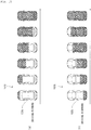
- the processor is further configured to display, based on the turn-around planning information, a progress bar which is divided into a plurality of sections; and to control the display unit based on the second information so that a color of the progress bar is gradually changed in one direction.
- the turn-around planning information includes information about forward driving planning and reverse driving planning
- the processor is further configured to control the display unit so that a first section corresponding to forward driving planning and a second section corresponding to reverse driving planning are alternately displayed in the progress bar.
- the processor is further configured to control the display unit so that the first section and the second section are alternately and repeatedly displayed.
- the first information comprises forward distance planning information and reverse distance planning information
- the second information comprises forward driving distance information based on the forward distance planning information, and reverse driving distance information based on reverse distance planning information.
- the processor is further configured to set a length of the first section based on the forward distance planning information; set a length of the second section based on the reverse distance planning information; and control the display unit so that a color of a/the progress bar is changed at a constant speed.
- the processor is further configured to set lengths of the first section and the second section to be uniform; based on the forward driving distance information, adjust a speed at which a color of the first section is changed; and based on the reverse driving distance information, adjust a speed at which a color of the second section is changed.
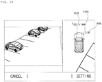
- the processor is further configured to control the display unit so that any one of a left-indicating arrow corresponding to left-steered driving situation information and a right-indicating arrow corresponding to right-steered driving situation information is displayed in the vicinity of the plurality of sections.
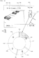
- the processor is further configured to display a first donut image corresponding to the first information; and to control the display unit based on the second information so that a color of the first donut image is gradually changed.
- the processor is further configured to display a second donut image corresponding to the turn-around planning information; and to control the display unit based on the forward driving situation information and the reverse driving situation information, so that a color of the second donut image is gradually changed in one direction.
- the processor is further configured to control the display unit so that the second donut image is reset at a turn-around time.
- the processor is further configured to, based on a left-steered driving situation information and a right steered driving situation information, determine a direction in which a color of the second donut image (1320) is changed.
- a vehicle as described in this specification may include an automobile and a motorcycle.
- a description will be given based on an automobile.
- a vehicle as described in this specification may include all of an internal combustion engine vehicle including an engine as a power source, a hybrid vehicle including both an engine and an electric motor as a power source, and an electric vehicle including an electric motor as a power source.
- the left side of the vehicle refers to the left side in the forward driving direction of the vehicle
- the right side of the vehicle refers to the right side in the forward driving direction of the vehicle
- FIG. 1 is a view of the external appearance of a vehicle according to an embodiment of the present invention.
- FIG. 2 is different angled views of a vehicle according to an embodiment of the present invention.
- FIGS. 3 and 4 are views of the internal configuration of a vehicle according to an embodiment of the present invention.
- FIGS. 5 and 6 are views for explanation of objects according to an embodiment of the present invention.
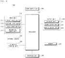
- FIG. 7 is a block diagram illustrating a vehicle according to an embodiment of the present invention.
- a vehicle 100 may include a plurality of wheels, which are rotated by a power source, and a steering input device 510 for controlling a driving direction of the vehicle 100.
- the vehicle 100 may be an autonomous vehicle.
- the vehicle 100 may switch to an autonomous driving mode or a manual mode in response to a user input.
- the vehicle 100 may switch from a manual mode to an autonomous driving mode, or vice versa.
- the vehicle 100 may switch to the autonomous driving mode or to the manual mode based on driving situation information.
- the driving situation information may include at least one of the following: information on an object located outside the vehicle 100, navigation information, and vehicle state information.
- the vehicle 100 may switch from the manual mode to the autonomous driving mode, or vice versa, based on driving situation information generated by the object detection apparatus 300.
- the vehicle 100 may switch from the manual mode to the autonomous driving mode, or vice versa, based on driving situation information received through a communication apparatus 400.
- the vehicle 100 may switch from the manual mode to the autonomous driving mode, or vice versa, based on information, data, and a signal provided from an external device.
- the autonomous vehicle 100 may operate based on a vehicle travel system 700.
- the autonomous vehicle 100 may operate based on information, data, or signals generated by a driving system 710, a parking-out system 740, and a parking system 750.
- the autonomous vehicle 100 may receive a user input for driving of the vehicle 100 through a driving manipulation apparatus 500. In response to the user input received through the driving manipulation apparatus 500, the vehicle 100 may operate.
- overall length means the length from the front end to the rear end of the vehicle 100
- the term “overall width” means the width of the vehicle 100
- the term “overall height” means the height from the bottom of the wheel to the roof.
- the term “overall length direction L” may mean the reference direction for the measurement of the overall length of the vehicle 100
- the term “overall width direction W” may mean the reference direction for the measurement of the overall width of the vehicle 100
- the term “overall height direction H” may mean the reference direction for the measurement of the overall height of the vehicle 100.
- the vehicle 100 may include the user interface apparatus 200, the object detection apparatus 300, the communication apparatus 400, the driving manipulation apparatus 500, a vehicle drive apparatus 600, the vehicle travel system 700, a navigation system 770, a sensing unit 120, an interface 130, a memory 140, a controller 170, and a power supply unit 190.
- the vehicle 100 may further include other components in addition to the aforementioned components, or may not include some of the aforementioned components.
- the user interface apparatus 200 is provided to support communication between the vehicle 100 and a user.
- the user interface apparatus 200 may receive a user input, and provide information generated in the vehicle 100 to the user.
- the vehicle 100 may enable User Interfaces (UI) or User Experience (UX) through the user interface apparatus 200.
- UI User Interfaces
- UX User Experience
- the user interface apparatus 200 may include an input unit 210, an internal camera 220, a biometric sensing unit 230, an output unit 250, and a processor 270.
- the user interface apparatus 200 may further include other components in addition to the aforementioned components, or may not include some of the aforementioned components.
- the input unit 210 is configured to receive information from a user, and data collected in the input unit 210 may be analyzed by the processor 270 and then processed into a control command of the user.
- the input unit 210 may be disposed inside the vehicle 100.
- the input unit 210 may be disposed in a region of a steering wheel, a region of an instrument panel, a region of a seat, a region of each pillar, a region of a door, a region of a center console, a region of a head lining, a region of a sun visor, a region of a windshield, or a region of a window.
- the input unit 210 may include a voice input unit 211, a gesture input unit 212, a touch input unit 213, and a mechanical input unit 214.
- the voice input unit 211 may convert a voice input of a user into an electrical signal.
- the converted electrical signal may be provided to the processor 270 or the controller 170.
- the voice input unit 211 may include one or more microphones.
- the gesture input unit 212 may convert a gesture input of a user into an electrical signal.
- the converted electrical signal may be provided to the processor 270 or the controller 170.
- the gesture input unit 212 may include at least one selected from among an infrared sensor and an image sensor for sensing a gesture input of a user.
- the gesture input unit 212 may sense a three-dimensional (3D) gesture input of a user.
- the gesture input unit 212 may include a plurality of light emitting units for outputting infrared light, or a plurality of image sensors.
- the gesture input unit 212 may sense a 3D gesture input by employing a Time of Flight (TOF) scheme, a structured light scheme, or a disparity scheme.
- TOF Time of Flight
- the touch input unit 213 may convert a user's touch input into an electrical signal.
- the converted electrical signal may be provided to the processor 270 or the controller 170.
- the touch input unit 213 may include a touch sensor for sensing a touch input of a user.
- the touch input unit 210 may be formed integral with a display unit 251 to implement a touch screen.
- the touch screen may provide an input interface and an output interface between the vehicle 100 and the user.
- the mechanical input unit 214 may include at least one selected from among a button, a dome switch, a jog wheel, and a jog switch. An electrical signal generated by the mechanical input unit 214 may be provided to the processor 270 or the controller 170.
- the mechanical input unit 214 may be located on a steering wheel, a center fascia, a center console, a cockpit module, a door, etc.
- the internal camera 220 may acquire images of the inside of the vehicle 100.
- the processor 270 may sense a user's condition based on the images of the inside of the vehicle 100.
- the processor 270 may acquire information on an eye gaze of the user.
- the processor 270 may sense a gesture of the user from the images of the inside of the vehicle 100.
- the biometric sensing unit 230 may acquire biometric information of the user.
- the biometric sensing unit 230 may include a sensor for acquire biometric information of the user, and may utilize the sensor to acquire finger print information, heart rate information, etc. of the user.
- the biometric information may be used for user authentication.
- the output unit 250 is configured to generate a visual, audio, or tactile output.
- the output unit 250 may include at least one selected from among a display unit 251, a sound output unit 252, and a haptic output unit 253.
- the display unit 251 may display graphic objects corresponding to various types of information.
- the display unit 251 may include at least one selected from among a Liquid Crystal Display (LCD), a Thin Film Transistor-Liquid Crystal Display (TFT LCD), an Organic Light-Emitting Diode (OLED), a flexible display, a 3D display, and an e-ink display.
- LCD Liquid Crystal Display
- TFT LCD Thin Film Transistor-Liquid Crystal Display
- OLED Organic Light-Emitting Diode
- the display unit 251 may form an inter-layer structure together with the touch input unit 213, or may be integrally formed with the touch input unit 213 to implement a touch screen.
- the display unit 251 may be implemented as a Head Up Display (HUD). When implemented as a HUD, the display unit 251 may include a projector module in order to output information through an image projected on a windshield or a window.
- HUD Head Up Display
- the display unit 251 may include a transparent display.
- the transparent display may be attached on the windshield or the window.
- the transparent display may display a predetermined screen with a predetermined transparency.
- the transparent display may include at least one selected from among a transparent Thin Film Electroluminescent (TFEL) display, an Organic Light Emitting Diode (OLED) display, a transparent Liquid Crystal Display (LCD), a transmissive transparent display, and a transparent Light Emitting Diode (LED) display.
- TFEL Thin Film Electroluminescent
- OLED Organic Light Emitting Diode
- LCD transparent Liquid Crystal Display
- LED transparent Light Emitting Diode
- the transparency of the transparent display may be adjustable.
- the user interface apparatus 200 may include a plurality of display units 251a to 251g.
- the display unit 251 may be disposed in a region of a steering wheel, a region 251a, 251b, or 251e of an instrument panel, a region 251d of a seat, a region 251f of each pillar, a region 251g of a door, a region of a center console, a region of a head lining, a region of a sun visor, a region 251c of a windshield, or a region 251h of a window.
- the sound output unit 252 converts an electrical signal from the processor 270 or the controller 170 into an audio signal, and outputs the audio signal. To this end, the sound output unit 252 may include one or more speakers.
- the haptic output unit 253 generates a tactile output.
- the haptic output unit 253 may operate to vibrate a steering wheel, a safety belt, and seats 110FL, 110FR, 110RL, and 110RR so as to allow a user to recognize the output.
- the processor 270 may control the overall operation of each unit of the user interface apparatus 200.
- the user interface apparatus 200 may include a plurality of processors 270 or may not include the processor 270.
- the user interface apparatus 200 may operate under control of the controller 170 or a processor of a different device inside the vehicle 100.
- the user interface apparatus 200 may be referred to as a display device for vehicle.
- the user interface apparatus 200 may operate under control of the controller 170.
- the object detection apparatus 300 is configured to detect an object outside the vehicle 100.
- the object detection apparatus 300 may generate information on the object based on sensing data.
- the information on the object may include information about the presence of the object, location information of the object, information on a distance between the vehicle 100 and the object, and information on a speed of movement of the vehicle 100 relative to the object.
- the object may include various objects related to travelling of the vehicle 100.
- an object o may include a lane OB10, a nearby vehicle OB11, a pedestrian OB12, a two-wheeled vehicle OB13, a traffic signal OB14 and OB15, a light, a road, a structure, a bump, a geographical feature, an animal, etc.
- the lane OB10 may be a lane in which the vehicle 100 is traveling, a lane next to the lane in which the vehicle 100 is traveling, or a lane in which a different vehicle is travelling in the opposite direction.
- the lane OB10 may include left and right lines that define the lane.
- the lane may be a concept including an intersection.
- the nearby vehicle OB11 may be a vehicle that is travelling in the vicinity of the vehicle 100.
- the nearby vehicle OB11 may be a vehicle within a predetermined distance from the vehicle 100.
- the nearby vehicle OB11 may be a vehicle that is preceding or following the vehicle 100.
- the pedestrian OB12 may be a person located in the vicinity of the vehicle 100.
- the pedestrian OB12 may be a person within a predetermined distance from the vehicle 100.
- the pedestrian OB12 may be a person on a sidewalk or on the roadway.
- the two-wheeled vehicle OB13 is a vehicle located in the vicinity of the vehicle 100 and moves with two wheels.
- the two-wheeled vehicle OB13 may be a vehicle that has two wheels within a predetermined distance from the vehicle 100.
- the two-wheeled vehicle OB13 may be a motorcycle or a bike on a sidewalk or the roadway.
- the traffic signal may include a traffic light OB15, a traffic sign plate OB14, and a pattern or text painted on a road surface.
- the light may be light generated by a lamp provided in the nearby vehicle.
- the light may be light generated by a street light.
- the light may be solar light.
- the road may include a road surface, a curve, and slopes, such as an upward slope and a downward slope.
- the structure may be a body located around the road in the state of being fixed onto the ground.
- the structure may include a streetlight, a roadside tree, a building, a traffic light, a bridge, a curb, and a wall.
- the geographical feature may include a mountain and a hill.
- the object may be classified as a movable object or a stationary object.
- the movable object may be a concept including a moving nearby vehicle and a moving pedestrian.
- the stationary object may be a concept including a traffic signal, a road, a structure, a stopped nearby vehicle, and a stopped pedestrian.
- the object detection apparatus 300 may include a camera 310, a radar 320, a lidar 330, an ultrasonic sensor 340, an infrared sensor 350, and a processor 370.
- the object detection apparatus 300 may further include other components in addition to the aforementioned components, or may not include some of the aforementioned components.
- the camera 310 may be located at an appropriate position outside the vehicle 100 in order to acquire images of the outside of the vehicle 100.
- the camera 310 may be a mono camera, a stereo camera 310a, an Around View Monitoring (AVM) camera 310b, or a 360-degree camera.
- AVM Around View Monitoring
- the camera 310 may acquire location information of an object, information on a distance to the object, and information on speed relative to the object.
- the camera 310 may acquire information on a distance to the object and information on speed relative to the object.
- the camera 310 may acquire the information on a distance to the object and the information on speed relative to the object, by using a pin hole model or profiling a road surface.
- the camera 310 may acquire the information on a distance to the object and the information on the speed relative to the object, based on information on disparity in stereo images acquired by a stereo camera 310a.
- the camera 310 may be disposed near a front windshield in the vehicle 100 in order to acquire images of the front of the vehicle 100.
- the camera 310 may be disposed around a front bumper or a radiator grill.
- the camera 310 may be disposed near a rear glass in the vehicle 100 in order to acquire images of the rear of the vehicle 100.
- the camera 310 may be disposed around a rear bumper, a trunk, or a tailgate.
- the camera 310 may be disposed near at least one of the side windows in the vehicle 100 in order to acquire images of the side of the vehicle 100.
- the camera 310 may be disposed around a side mirror, a fender, or a door.
- the camera 310 may provide an acquired image to the processor 370.
- the radar 320 may include an electromagnetic wave transmission unit and an electromagnetic wave reception unit.
- the radar 320 may be realized as a pulse radar or a continuous wave radar depending on the principle of emission of an electronic wave.
- the radar 320 may be realized as a Frequency Modulated Continuous Wave (FMCW) type radar or a Frequency Shift Keying (FSK) type radar depending on the waveform of a signal.
- FMCW Frequency Modulated Continuous Wave
- FSK Frequency Shift Keying
- the radar 320 may detect an object through the medium of an electromagnetic wave by employing a time of flight (TOF) scheme or a phase-shift scheme, and may detect a location of the detected object, the distance to the detected object, and the speed relative to the detected object
- TOF time of flight
- the radar 320 may be located at an appropriate position outside the vehicle 100 in order to sense an object located in front of the vehicle 100, an object located to the rear of the vehicle 100, or an object located to the side of the vehicle 100.
- the lidar 330 may include a laser transmission unit and a laser reception unit.
- the lidar 330 may be implemented by the TOF scheme or the phase-shift scheme.
- the lidar 330 may be implemented as a drive type lidar or a non-drive type lidar.
- the lidar 300 When implemented as the drive type lidar, the lidar 300 may rotate by a motor and detect an object in the vicinity of the vehicle 100.
- the lidar 300 may utilize a light steering technique to detect an object located within a predetermined distance from the vehicle 100.
- the vehicle 100 may include a plurality of non-driving type lidars 330.
- the lidar 330 may detect an object through the medium of laser light by employing the TOF scheme or the phase-shift scheme, and may detect a location of the detected object, the distance to the detected object, and the speed relative to the detected object.
- the lidar 330 may be located at an appropriate position outside the vehicle 100 in order to sense an object located in front of the vehicle 100, an object located to the rear of the vehicle 100, or an object located to the side of the vehicle 100.
- the ultrasonic sensor 340 may include an ultrasonic wave transmission unit and an ultrasonic wave reception unit.
- the ultrasonic sensor 340 may detect an object based on an ultrasonic wave, and may detect a location of the detected object, the distance to the detected object, and the speed relative to the detected object.
- the ultrasonic sensor 340 may be located at an appropriate position outside the vehicle 100 in order to detect an object located in front of the vehicle 100, an object located to the rear of the vehicle 100, and an object located to the side of the vehicle 100.
- the infrared sensor 350 may include an infrared light transmission unit and an infrared light reception unit.
- the infrared sensor 340 may detect an object based on infrared light, and may detect a location of the detected object, the distance to the detected object, and the speed relative to the detected object.
- the infrared sensor 350 may be located at an appropriate position outside the vehicle 100 in order to sense an object located in front of the vehicle 100, an object located to the rear of the vehicle 100, or an object located to the side of the vehicle 100.
- the processor 370 may control the overall operation of each unit of the object detection apparatus 300.
- the processor 370 may detect or classify an object by comparing pre-stored data with data sensed by the camera 310, the radar 320, the lidar 330, the ultrasonic sensor 340, and the infrared sensor 350.
- the processor 370 may detect and track an object based on acquired images.
- the processor 370 may, for example, calculate the distance to the object and the speed relative to the object.
- the processor 370 may acquire information on the distance to the object and information on the speed relative to the object based on a variation in size over time of the object in acquired images.
- the processor 370 may acquire information on the distance to the object or information on the speed relative to the object by using a pin hole model or by profiling a road surface.
- the processor 370 may acquire information on the distance to the object and information on the speed relative to the object based on information on disparity in stereo images acquired from the stereo camera 310a.
- the processor 370 may detect and track an object based on a reflection electromagnetic wave which is formed as a result of reflection a transmission electromagnetic wave by the object. Based on the electromagnetic wave, the processor 370 may, for example, calculate the distance to the object and the speed relative to the object.
- the processor 370 may detect and track an object based on a reflection laser light which is formed as a result of reflection of transmission laser by the object. Based on the laser light, the processor 370 may, for example, calculate the distance to the object and the speed relative to the object.
- the processor 370 may detect and track an object based on a reflection ultrasonic wave which is formed as a result of reflection of a transmission ultrasonic wave by the object. Based on the ultrasonic wave, the processor 370 may, for example, calculate the distance to the object and the speed relative to the object.
- the processor 370 may detect and track an object based on reflection infrared light which is formed as a result of reflection of transmission infrared light by the object. Based on the infrared light, the processor 370 may, for example, calculate the distance to the object and the speed relative to the object.
- the object detection apparatus 300 may include a plurality of processors 370 or may not include the processor 370.
- each of the camera 310, the radar 320, the lidar 330, the ultrasonic sensor 340, and the infrared sensor 350 may include its own processor.
- the object detection apparatus 300 may operate under control of the controller 170 or a processor inside the vehicle 100.
- the object detection apparatus 300 may operate under control of the controller 170.
- the communication apparatus 400 is configured to perform communication with an external device.
- the external device may be a nearby vehicle, a mobile terminal, or a server.
- the communication apparatus 400 may include at least one selected from among a transmission antenna, a reception antenna, a Radio Frequency (RF) circuit capable of implementing various communication protocols, and an RF device.
- RF Radio Frequency
- the communication apparatus 400 may include a short-range communication unit 410, a location information unit 420, a V2X communication unit 430, an optical communication unit 440, a broadcast transmission and reception unit 450, an Intelligent Transport Systems (ITS) communication unit 460, and a processor 470.
- a short-range communication unit 410 may include a short-range communication unit 410, a location information unit 420, a V2X communication unit 430, an optical communication unit 440, a broadcast transmission and reception unit 450, an Intelligent Transport Systems (ITS) communication unit 460, and a processor 470.
- ITS Intelligent Transport Systems
- the communication apparatus 400 may further include other components in addition to the aforementioned components, or may not include some of the aforementioned components.
- the short-range communication unit 410 is configured to perform short-range communication.
- the short-range communication unit 410 may support short-range communication using at least one selected from among BluetoothTM, Radio Frequency IDdentification (RFID), Infrared Data Association (IrDA), Ultra-WideBand (UWB), ZigBee, Near Field Communication (NFC), Wireless-Fidelity (Wi-Fi), Wi-Fi Direct, and Wireless USB (Wireless Universal Serial Bus).
- RFID Radio Frequency IDdentification
- IrDA Infrared Data Association
- UWB Ultra-WideBand
- ZigBee Near Field Communication
- NFC Near Field Communication
- Wi-Fi Wireless-Fidelity
- Wi-Fi Direct Wireless USB (Wireless Universal Serial Bus).
- the short-range communication unit 410 may form wireless area networks to perform short-range communication between the vehicle 100 and at least one external device.
- the location information unit 420 is configured to acquire location information of the vehicle 100.
- the location information unit 420 may include a Global Positioning System (GPS) module or a Differential Global Positioning System (DGPS) module.
- GPS Global Positioning System
- DGPS Differential Global Positioning System
- the V2X communication unit 430 is configured to perform wireless communication between a vehicle and a server (that is, vehicle to infra (V2I) communication), wireless communication between a vehicle and a nearby vehicle (that is, vehicle to vehicle (V2V) communication), or wireless communication between a vehicle and a pedestrian (that is, vehicle to pedestrian(V2P) communication).
- a server that is, vehicle to infra (V2I) communication
- wireless communication between a vehicle and a nearby vehicle that is, vehicle to vehicle (V2V) communication
- wireless communication between a vehicle and a pedestrian that is, vehicle to pedestrian(V2P) communication.
- the optical communication unit 440 is configured to perform communication with an external device through the medium of light.
- the optical communication unit 440 may include a light emitting unit, which converts an electrical signal into an optical signal and transmits the optical signal to the outside, and a light receiving unit which converts a received optical signal into an electrical signal.
- the light emitting unit may be integrally formed with a lamp provided included in the vehicle 100.
- the broadcast transmission and reception unit 450 is configured to receive a broadcast signal from an external broadcasting management server or transmit a broadcast signal to the broadcasting management server through a broadcasting channel.
- the broadcasting channel may include a satellite channel, and a terrestrial channel.
- the broadcast signal may include a TV broadcast signal, a radio broadcast signal, and a data broadcast signal.
- the ITS communication unit 460 may exchange information, data, or signals with a traffic system.
- the ITS communication unit 460 may provide acquired information or data to the traffic system.
- the ITS communication unit 460 may receive information, data, or signals from the traffic system.
- the ITS communication unit 460 may receive traffic volume information from the traffic system and provide the traffic volume information to the controller 170.
- the ITS communication unit 460 may receive a control signal from the traffic system, and provide the control signal to the controller 170 or a processor provided in the vehicle 100.
- the processor 470 may control the overall operation of each unit of the communication apparatus 400.
- the communication apparatus 400 may include a plurality of processors 470, or may not include the processor 470.
- the communication apparatus 400 may operate under control of the controller 170 or a processor of a device inside of the vehicle 100.
- the communication apparatus 400 may implement a vehicle display device, together with the user interface apparatus 200.
- the vehicle display device may be referred to as a telematics device or an Audio Video Navigation (AVN) device.
- APN Audio Video Navigation
- the communication apparatus 400 may operate under control of the controller 170.
- the driving manipulation apparatus 500 is configured to receive a user input for driving the vehicle 100.
- the vehicle 100 may operate based on a signal provided by the driving manipulation apparatus 500.
- the driving manipulation apparatus 500 may include a steering input device 510, an acceleration input device 530, and a brake input device 570.
- the steering input device 510 may receive a user input with regard to the direction of travel of the vehicle 100.
- the steering input device 510 may take the form of a wheel to enable a steering input through the rotation thereof.
- the steering input device may be provided as a touchscreen, a touch pad, or a button.
- the acceleration input device 530 may receive a user input for acceleration of the vehicle 100.
- the brake input device 570 may receive a user input for deceleration of the vehicle 100.
- Each of the acceleration input device 530 and the brake input device 570 may take the form of a pedal.
- the acceleration input device or the break input device may be configured as a touch screen, a touch pad, or a button.
- the driving manipulation apparatus 500 may operate under control of the controller 170.
- the vehicle drive apparatus 600 is configured to electrically control the operation of various devices of the vehicle 100.
- the vehicle drive apparatus 600 may include a power train drive unit 610, a chassis drive unit 620, a door/window drive unit 630, a safety apparatus drive unit 640, a lamp drive unit 650, and an air conditioner drive unit 660.
- the vehicle drive apparatus 600 may further include other components in addition to the aforementioned components, or may not include some of the aforementioned components.
- the vehicle drive apparatus 600 may include a processor. Each unit of the vehicle drive apparatus 600 may include its own processor.
- the power train drive unit 610 may control the operation of a power train.
- the power train drive unit 610 may include a power source drive unit 611 and a transmission drive unit 612.
- the power source drive unit 611 may control a power source of the vehicle 100.
- the power source drive unit 611 may perform electronic control of the engine. As such the power source drive unit 611 may control, for example, the output torque of the engine. The power source drive unit 611 may adjust the output toque of the engine under control of the controller 170.
- the power source drive unit 611 may control the motor.
- the power source drive unit 611 may control, for example, the RPM and toque of the motor under control of the controller 170.
- the transmission drive unit 612 may control a transmission.
- the transmission drive unit 612 may adjust the state of the transmission.
- the transmission drive unit 612 may adjust a state of the transmission to a drive (D), reverse (R), neutral (N), or park (P) state.
- the transmission drive unit 612 may adjust a gear-engaged state to the drive position D.
- the chassis drive unit 620 may control the operation of a chassis.
- the chassis drive unit 620 may include a steering drive unit 621, a brake drive unit 622, and a suspension drive unit 623.
- the steering drive unit 621 may perform electronic control of a steering apparatus provided inside the vehicle 100.
- the steering drive unit 621 may change the direction of travel of the vehicle 100.
- the brake drive unit 622 may perform electronic control of a brake apparatus provided inside the vehicle 100. For example, the brake drive unit 622 may reduce the speed of the vehicle 100 by controlling the operation of a brake located at a wheel.
- the brake drive unit 622 may control a plurality of brakes individually.
- the brake drive unit 622 may apply a different degree-braking force to each wheel.
- the suspension drive unit 623 may perform electronic control of a suspension apparatus inside the vehicle 100. For example, when the road surface is uneven, the suspension drive unit 623 may control the suspension apparatus so as to reduce the vibration of the vehicle 100.
- the suspension drive unit 623 may control a plurality of suspensions individually.
- the door/window drive unit 630 may perform electronic control of a door apparatus or a window apparatus inside the vehicle 100.
- the door/window drive unit 630 may include a door drive unit 631 and a window drive unit 632.
- the door drive unit 631 may control the door apparatus.
- the door drive unit 631 may control opening or closing of a plurality of doors included in the vehicle 100.
- the door drive unit 631 may control opening or closing of a trunk or a tail gate.
- the door drive unit 631 may control opening or closing of a sunroof.
- the window drive unit 632 may perform electronic control of the window apparatus.
- the window drive unit 632 may control opening or closing of a plurality of windows included in the vehicle 100.
- the safety apparatus drive unit 640 may perform electronic control of various safety apparatuses provided inside the vehicle 100.
- the safety apparatus drive unit 640 may include an airbag drive unit 641, a safety belt drive unit 642, and a pedestrian protection equipment drive unit 643.
- the airbag drive unit 641 may perform electronic control of an airbag apparatus inside the vehicle 100. For example, upon detection of a dangerous situation, the airbag drive unit 641 may control an airbag to be deployed.
- the safety belt drive unit 642 may perform electronic control of a seatbelt apparatus inside the vehicle 100. For example, upon detection of a dangerous situation, the safety belt drive unit 642 may control passengers to be fixed onto seats 110FL, 110FR, 110RL, and 110RR with safety belts.
- the pedestrian protection equipment drive unit 643 may perform electronic control of a hood lift and a pedestrian airbag. For example, upon detection of a collision with a pedestrian, the pedestrian protection equipment drive unit 643 may control a hood lift and a pedestrian airbag to be deployed.
- the lamp drive unit 650 may perform electronic control of various lamp apparatuses provided inside the vehicle 100.
- the air conditioner drive unit 660 may perform electronic control of an air conditioner inside the vehicle 100. For example, when the inner temperature of the vehicle 100 is high, an air conditioner drive unit 660 may operate the air conditioner so as to supply cool air to the inside of the vehicle 100.
- the vehicle drive apparatus 600 may include a processor. Each unit of the vehicle dive device 600 may include its own processor.
- the vehicle drive apparatus 600 may operate under control of the controller 170.
- the vehicle travel system 700 is a system for controlling the overall driving operation of the vehicle 100.
- the vehicle travel system 700 may operate in the autonomous driving mode.
- the vehicle travel system 700 may include the driving system 710, the parking-out system 740, and the parking system 750.
- the vehicle travel system 700 may further include other components in addition to the aforementioned components, or may not include some of the aforementioned component.
- the vehicle travel system 700 may include a processor. Each unit of the vehicle travel system 700 may include its own processor.
- the vehicle travel system 700 in the case where the vehicle travel system 700 is implemented as software, the vehicle travel system 700 may be a subordinate concept of the controller 170.
- the vehicle travel system 700 may be a concept including at least one selected from among the user interface apparatus 200, the object detection apparatus 300, the communication apparatus 400, the driving manipulation apparatus 500, the vehicle drive apparatus 600, the navigation system 770, the sensing unit 120, and the controller 170.
- the driving system 710 may perform driving of the vehicle 100.
- the driving system 710 may perform driving of the vehicle 100 by providing a control signal to the vehicle drive apparatus 600 based on navigation information from the navigation system 770.
- the driving system 710 may perform driving of the vehicle 100 by providing a control signal to the vehicle drive apparatus 600 based on information on an object received from the object detection apparatus 300.
- the driving system 710 may perform driving of the vehicle 100 by providing a control signal to the vehicle drive apparatus 600 based on a signal from an external device through the communication apparatus 400.
- the driving system 710 may be a system which includes at least one of the user interface apparatus 200, the object detection apparatus 300, the communication apparatus 400, the driving manipulation apparatus 500, the vehicle driving device 600, the navigation system 770, the sensing unit 120, and the controller 170, and which performs driving of the vehicle 100.
- the driving system 710 may be referred to as a vehicle driving control apparatus.
- the parking-out system 740 may perform an operation of pulling the vehicle 100 out of a parking space.
- the parking-out system 740 may perform an operation of pulling the vehicle 100 out of a parking space, by providing a control signal to the vehicle drive apparatus 600 based on navigation information from the navigation system 770.
- the parking-out system 740 may perform an operation of pulling the vehicle 100 out of a parking space, by providing a control signal to the vehicle drive apparatus 600 based on information on an object received from the object detection apparatus 300.
- the parking-out system 740 may perform an operation of pulling the vehicle 100 out of a parking space, by providing a control signal to the vehicle drive apparatus 600 based on a signal received from an external device.
- the parking-out system 740 may be a system which includes at least one of the user interface apparatus 200, the object detection apparatus 300, the communication apparatus 400, the driving manipulation apparatus 500, the vehicle driving device 600, the navigation system 770, the sensing unit 120, and the controller 170, and which performs an operation of pulling the vehicle 100 out of a parking space.
- the parking-out system 740 may be referred to as a vehicle parking-out control apparatus.
- the parking system 750 may perform an operation of parking the vehicle 100 in a parking space.
- the parking system 750 may perform an operation of parking the vehicle 100 in a parking space, by providing a control signal to the vehicle drive apparatus 600 based on navigation information from the navigation system 770.
- the parking system 750 may perform an operation of parking the vehicle 100 in a parking space, by providing a control signal to the vehicle drive apparatus 600 based on information on an object received from the object detection apparatus 300.
- the parking system 750 may perform an operation of parking the vehicle 100 in a parking space, by providing a control signal to the vehicle drive apparatus 600 based on a signal from an external device.
- the parking system 750 may be a system which includes at least one of the user interface apparatus 200, the object detection apparatus 300, the communication apparatus 400, the driving manipulation apparatus 500, the vehicle driving device 600, the navigation system 770, the sensing unit 120, and the controller 170, and which performs an operation of parking the vehicle 100.
- the parking system 750 may be referred to as a vehicle parking control apparatus.
- the navigation system 770 may provide navigation information.
- the navigation information may include at least one selected from among map information, information on a set destination, information on a route to the set destination, information on various objects along the route, lane information, and information on a current location of the vehicle.
- the navigation system 770 may include a memory and a processor.
- the memory may store navigation information.
- the processor may control the operation of the navigation system 770.
- the navigation system 770 may update pre-stored information by receiving information from an external device through the communication apparatus 400.
- the navigation system 770 may be classified as an element of the user interface apparatus 200.
- the sensing unit 120 may sense the state of the vehicle.
- the sensing unit 120 may include an Inertial Navigation Unit (IMU) sensor, a collision sensor, a wheel sensor, a speed sensor, a gradient sensor, a weight sensor, a heading sensor, a position module, a vehicle forward/reverse movement sensor, a battery sensor, a fuel sensor, a tire sensor, a steering sensor based on the rotation of the steering wheel, an in-vehicle temperature sensor, an in-vehicle humidity sensor, an ultrasonic sensor, an illumination sensor, an accelerator pedal position sensor, a brake pedal position sensor, and a location sensor (for example, a GPS sensor).
- IMU Inertial Navigation Unit
- the IMU sensor may include at least one of an accelerometer, a gyro sensor, and a magnetic sensor.
- the sensing unit 120 may acquire sensing signals with regard to, for example, vehicle attitude information, vehicle motion information, vehicle yaw information, vehicle roll information, vehicle pitch information, vehicle collision information, vehicle driving direction information, vehicle location information (GPS information), vehicle angle information, vehicle speed information, vehicle acceleration information, vehicle tilt information, vehicle forward/reverse movement information, battery information, fuel information, tire information, vehicle lamp information, in-vehicle temperature information, in-vehicle humidity information, steering-wheel rotation angle information, out-of-vehicle illumination information, information about the pressure applied to an accelerator pedal, and information about the pressure applied to a brake pedal.
- vehicle attitude information for example, vehicle attitude information, vehicle motion information, vehicle yaw information, vehicle roll information, vehicle pitch information, vehicle collision information, vehicle driving direction information, vehicle location information (GPS information), vehicle angle information, vehicle speed information, vehicle acceleration information, vehicle tilt information, vehicle forward/reverse movement information, battery information, fuel information, tire information, vehicle lamp information, in-vehicle temperature information, in-vehicle humidity information
- the sensing unit 120 may further include, for example, an accelerator pedal sensor, a pressure sensor, an engine speed sensor, an Air Flow-rate Sensor (AFS), an Air Temperature Sensor (ATS), a Water Temperature Sensor (WTS), a Throttle Position Sensor (TPS), a Top Dead Center (TDC) sensor, and a Crank Angle Sensor (CAS).
- AFS Air Flow-rate Sensor
- ATS Air Temperature Sensor
- WTS Water Temperature Sensor
- TPS Throttle Position Sensor
- TDC Top Dead Center
- CAS Crank Angle Sensor
- the sensing unit 120 may generate vehicle state information based on sensing data.
- the vehicle state information may be information that is generated based on data sensed by various sensors provided inside the vehicle 100.
- the vehicle state information may include vehicle position information, vehicle speed information, vehicle tilt information, vehicle weight information, vehicle direction information, vehicle battery information, vehicle fuel information, vehicle tire pressure information, vehicle steering information, in-vehicle temperature information, in-vehicle humidity information, pedal position information, vehicle engine temperature information, etc.
- the interface 130 may serve as a passage for various kinds of external devices that are connected to the vehicle 100.
- the interface 130 may have a port that is connectable to a mobile terminal and may be connected to the mobile terminal via the port. In this case, the interface 130 may exchange data with the mobile terminal.
- the interface 130 may serve as a passage for the supply of electrical energy to a mobile terminal connected thereto.
- the interface 130 may provide electrical energy, supplied from the power supply unit 190, to the mobile terminal under control of the controller 170.
- the memory 140 is electrically connected to the controller 170.
- the memory 140 may store basic data for each unit, control data for the operational control of each unit, and input/output data.
- the memory 140 may be any of various hardware storage devices, such as a ROM, a RAM, an EPROM, a flash drive, and a hard drive.
- the memory 140 may store various data for the overall operation of the vehicle 100, such as programs for the processing or control of the controller 170.
- the memory 140 may be integrally formed with the controller 170, or may be provided as an element of the controller 170.
- the controller 170 may control the overall operation of each unit inside the vehicle 100.
- the controller 170 may be referred to as an Electronic Controller (ECU).
- ECU Electronic Controller
- the power supply unit 190 may supply power required to operate each component under control of the controller 170.
- the power supply unit 190 may receive power from, for example, a battery inside the vehicle 100.
- At least one processor and the controller 170 included in the vehicle 100 may be implemented using at least one selected from among Application Specific Integrated Circuits (ASICs), Digital Signal Processors (DSPs), Digital Signal Processing Devices (DSPDs), Programmable Logic Devices (PLDs), Field Programmable Gate Arrays (FPGAs), processors, controllers, micro-controllers, microprocessors, and electric units for the implementation of other functions.
- ASICs Application Specific Integrated Circuits
- DSPs Digital Signal Processors
- DSPDs Digital Signal Processing Devices
- PLDs Programmable Logic Devices
- FPGAs Field Programmable Gate Arrays
- processors controllers, micro-controllers, microprocessors, and electric units for the implementation of other functions.
- FIG. 8 is a block diagram illustrating a user interface apparatus according for vehicle to an embodiment of the present invention.
- a user interface apparatus 200 for vehicle may include an input unit 210, a memory 240, an interface unit 245, an output unit 250, a processor 270, and a power supply unit 290.
- the user interface apparatus 200 may further include an internal camera 220 and a biometric sensing unit 230 individually or in combination.
- the user interface apparatus 200 shown in FIG. 8 includes the elements of the user interface apparatus 200 shown in FIG. 7 .
- the same descriptions provided above with reference to FIG. 7 are omitted.
- the description provided with reference to FIG. 7 may be applied to the input unit 210 and the biometric sensing unit 230.
- the memory 240 is electrically connected to the processor 270.
- the memory 240 may store basic data of each unit, control data for controlling the operation of each unit, and input/output data.
- the memory 240 may be any of various hardware storage devices, such as a ROM, a RAM, an EPROM, a flash drive, and a hard drive.
- the memory 240 may store various data for the overall operation of the user interface 200, such as programs for the processing or control of the processor 270.
- the memory 240 may be integrated with the processor 270, or may be an element of the processor 270.
- the interface unit 245 may exchange information, data, or a signal with a different device included in the vehicle 100.
- the interface unit 245 may transmit the received information, data, or signal to the processor 270.
- the interface unit 245 may transmit information, data, or a signal generated or processed by the processor 270 to a different device included in the vehicle 100.
- the interface unit 245 may receive information, data, or a signal from a different device included in the vehicle 100.
- the interface unit 245 may receive front view image information from the object detection apparatus 300.
- the interface unit 245 may receive driving situation information.
- the interface unit 245 may receive information on an object located outside the vehicle 100 from the object detection apparatus 300.
- the interface unit 245 may receive information on an object located in front of vehicle 100.
- the interface unit 245 may receive navigation information from the navigation system 770.
- the interface unit 245 may receive vehicle state information from the sensing unit 120.
- the interface unit 245 may receive information on a motion of the vehicle 100 from the sensing unit 120.
- Information, data, or a signal received by the interface unit 245 may be provided to the processor 270.
- the parking system 750 may generate first information about autonomous parking planning.
- the first information about autonomous parking planning may include at least one of parking start position information, parking goal position information, parking path information, turn-around planning information, forward driving planning information, reverse driving planning information, left steering planning information, right steering planning information, forward distance planning information, reverse distance planning information, forward driving speed planning information, and reverse driving speed planning information.
- the first information generated by the parking system 50 may be provided to the user interface apparatus 200.
- the interface unit 245 may receive the first information about autonomous parking planning.
- the interface unit 245 may transfer the first information to the processor 270.
- the object detection apparatus 300 may generate second information which is about a progress situation of an autonomous parking maneuver being performed based on autonomous parking planning.
- the object detection apparatus 300 may generate the second information based on sensing data generated by at least one of the camera 310, the radar 320, the lidar 330, the ultrasonic sensor 230, and the infrared sensor 350.
- the sensing unit 120 may generate second information, which is about a progress situation of an autonomous parking maneuver being performed based on autonomous parking planning.
- the sensing unit 120 may generate the second information based on at least one of an IMU sensor, a heading sensor, a speed sensor, a vehicle forward/backward sensor, a steering sensor, and a location sensor.
- the second information about a progress situation of an autonomous parking maneuver may include at least one of vehicle location information, vehicle speed information, turn-around driving situation information, forward driving situation information, reverse driving situation information, left-steered driving situation information, and right-steered driving situation information.
- Second information generated by the object detection apparatus 300 may be provided to the user interface apparatus 200.
- the interface unit 245 may receive second information, which is about a progress situation of an autonomous parking maneuver being performed based on autonomous parking planning.
- the interface unit 245 may transmit the second information to the processor 270.
- the output unit 250 may include a display unit 251, a sound output unit 252, and a haptic output unit 253.
- Description provided with reference to FIG. 7 may be applied to the output unit 250.
- description about the output unit 250 will be mainly about the display unit 251.
- the display unit 251 may operate under the control of the processor 270/
- the display unit 251 may be integrally formed with the touch input unit 213 to implement a touch screen.
- the display unit 251 When the display unit 251 is implemented as a touch screen, the display unit 251 may receive a user input.
- the processor 270 may control a parking operation based on the user input received by the display unit 251.
- the processor 270 may control the overall operation of each unit of the user interface apparatus 200.
- the processor 270 may receive first information about autonomous parking planning from the parking system 750 through the interface unit 245.
- the first information about autonomous parking planning may be defined as parking plan information necessary for the parking system 750 to perform an autonomous parking operation.
- the first information may include at least one of: turn-around planning information, driving direction planning information (for example, forward driving planning information and reverse driving planning information), and steering planning information (for example, left steering planning information and right steering planning information).
- driving direction planning information for example, forward driving planning information and reverse driving planning information
- steering planning information for example, left steering planning information and right steering planning information.
- the first information may further include autonomous parking path planning information.
- the autonomous parking path planning information may include one or more items of sub-path planning information.
- a plurality of items of sub-path planning information may match any one of forward driving planning information and reverse driving planning information.
- the turn-around planning information may include information about planning of transition from forward driving to reverse driving, and information about planning of transition from reverse driving to forward driving.
- the processor 270 may receive second information, which is about a progress situation of an autonomous parking maneuver being performed based on autonomous parking planning, from the object detection apparatus 300 or the sensing unit 120 through the interface unit 245.
- the second information about a progreds situation of autonomous parking may be defined as information about actual movement of the vehicle 100 in accordance of autonomous parking planning.
- the second information may include at least one of: turn-around driving situation information, driving direction situation information (for example, forward driving situation information and reverse driving situation information), and steered situation information (for example, left-steered driving situation information and right-steered driving situation information).
- driving direction situation information for example, forward driving situation information and reverse driving situation information
- steered situation information for example, left-steered driving situation information and right-steered driving situation information
- the turn-around driving situation information may include information on a situation where forward driving is transitioned to reverse driving, and information on a situation where reverse driving is switched to forward driving.
- the processor 270 may control the display unit 251 to display a graphic object corresponding to first information.
- the graphic object may be referred to as an indicator.
- the graphic object may be a figure image or a vehicle image.
- the figure image includes a two-dimensional (2D) figure image and a three-dimensional (3D) figure image.
- the following description is mainly about a 2D figure image.
- the figure image may be in any form of a bar, a circle, a donut, a polygon, a fan, and a line.
- the processor 270 may control the display unit 251 based on the second information to apply an animation effect to a graphic object.
- the processor 270 may control the display unit 251 based on the second information to apply a dynamic effect to a graphic object.
- the processor 270 may display a figure according to turn-around planning information.
- the processor 270 may display a figure that is divided into a plurality of sections according to turn-around planning information.
- the processor 270 may control the display unit 251 based on the second information so that at least one of a color, a shape, and a transparency of the figure is changed.
- the processor 270 may control the display unit 251 based on the second information so that at least one of a color, a shape, and a transparency of at least some of the plurality of sections is gradually changed.
- the shape may be a concept including an area, a length, or a height of a figure or one section thereof.
- the processor 270 may control the display unit 251 based on the second information so that a color of at least some of the plurality of sections is gradually changed from a first color into a second color.
- the processor 270 may control the display unit 251 based on the second information so that a shape of at least some of the plurality of sections is gradually changed from a first shape into a second shape.
- the processor 270 may control the display unit 251 based on the second information so that a transparency of at least some of the plurality of sections is gradually changed from a first state to a second state.
- the processor 270 may control the display unit 251 so that a plurality of sections of a figure is displayed in a manner of distinguishing at least one forward driving section corresponding to forward driving planning and at least one reverse driving section corresponding to reverse driving planning.
- the processor 270 may control the display unit 251 so that a text or image indicating forward driving planning information is displayed in the forward driving section.
- the processor 270 may control the display unit 251 so that a text or image indicating reverse driving planning information is displayed in the reverse driving section.
- the first information may further include forward distance planning information and reverse distance planning information.
- the first information may further include forward driving speed planning information and reverse driving speed planning information.
- the forward distance planning information may be information about planning of a distance to be travelled forward.
- the reverse distance planning information may be information about planning of a distance to be travelled backward.
- the processor 270 may set at least one of a color, a shape, a transparency of the forward driving section.
- the processor 270 may set at least one of a color, a shape, a transparency of the reverse driving section.
- the second information may further include forward driving distance information and reverse driving distance information.
- the second information may further include forward driving speed information and reverse driving speed information.
- the processor 270 may adjust a speed at which at least one of a color, a shape, and a transparency of the forward driving section is changed.
- the processor 270 may adjust a speed at which at least one of a color, a shape, and a transparency of the reverse driving section is changed.
- the processor 270 may control the display unit 251 based on turn-around planning information so as to display a progress bar which is divided into a plurality of sections.
- the processor 270 may control the display unit 251 based on the second information so that a color of the progress bar is gradually changed in one direction.
- the processor 270 may control the display unit 251 so that a first section corresponding to forward driving planning and a second section corresponding to reverse driving planning are sequentially displayed in the progress bar.
- the first information may include forward distance planning information and reverse distance planning information.
- the second information may include forward driving distance information based on the forward driving distance planning information, and reverse driving distance information based on the reverse distance planning information.
- the processor 270 may set a length of the first section based on the forward distance planning information.
- the processor 270 may set a length of the second section based on reverse distance planning information.
- the processor 270 may control the display unit 251 so that a color of the progress bar is changed at a constant speed.
- the processor 270 may set the respective lengths of the first section and the second section to be uniform.
- the processor 270 may adjust a speed at which a color of the first section is changed.
- the processor 270 may adjust a speed at which a color of the second section is changed.
- the processor 270 may control the display unit 251 so that at least one of a left-indicating arrow and a right-indicating arrow is displayed in the vicinity of the plurality of sections, wherein the left-indicating arrow corresponds to left-steered driving situation information and the right-indicating arrow corresponds to right-steered driving situation information.
- the processor 270 may display a first donut image corresponding to first information.
- the processor 270 may control the display unit 251 based on the second information so that a color of the first donut image is gradually changed.
- the processor 270 may display a second donut image corresponding to turn-around planning information.
- the processor 270 may control the display unit 251 based on forward driving situation information and reverse driving situation information, so that a color of the second donut image is gradually changed in one direction.
- the processor 270 may control the display unit 251 so that the second donut image is reset at a turn-around time.
- the processor 270 may determine a direction in which a color of the second donut image is gradually changed.
- the processor 270 may display a vehicle image.
- the processor 270 may control the display unit 251 so that the vehicle image is gradually changed from a first color to a second color in one direction.
- the processor 270 may control the display unit 251 so that the vehicle image is gradually changed from the first color to the second color in a direction from the front end to the rear end.
- the processor 270 may control the display unit 251 so that the vehicle image is gradually changed from the first color to the second color in a direction from the rear end to the front end.
- the processor 270 may control the display unit 251 so that a boundary formed by the first color and the second color is inclined at a specific angle.
- the processor 270 may determine the direction in which the boundary is inclined.
- the processor 270 may control the display unit 251 so that a color of at least one region of the vehicle image is gradually changed.
- the processor 270 may control the display unit 251 so that a position of one region is changed within the vehicle image.
- the processor 270 may provide a control signal to the vehicle drive apparatus 600.
- the processor 270 may receive a user input through the input unit 210.
- the processor 270 may provide a control signal to the vehicle drive apparatus 600 based on the received user input.
- the vehicle drive apparatus 600 may generate a driving signal based on a control signal received from the user interface apparatus 200.
- At least one of the power source drive unit 611, the transmission drive unit 612, the steering drive unit 621, and the brake drive unit 622 may generate a driving signal for at least one of a power source, a transmission, a steering device, and a brake device.
- the power supply unit 290 may supply power required for operation of each unit of the user interface apparatus 200.
- the power supply unit 290 may receive power from a battery provided inside a vehicle.
- FIG. 9 is a flowchart illustrating a user interface apparatus for vehicle according to an embodiment of the present invention.
- the processor 270 may receive first information about autonomous parking planning from the parking system 750 through the interface unit 245 in S910.
- the processor 270 may display a graphic object which matches the first information in S920.
- the graphic object may be a graphic object which is a visual version of the first information.
- the processor 270 may display a figure which matches the first information.
- the processor 270 may display a vehicle image which matches the first information.
- the processor 270 may receive second information, which is about a progress situation of an autonomous parking maneuver based on autonomous parking planning, from the object detection apparatus 300 or the sensing unit 120 through the interface unit 245 in S930.
- the processor 270 may control the display unit 251 based on the second information to apply an animation effect to the graphic object in S940.
- the processor 270 may apply a dynamic effect to the graphic object.
- the processor 270 may control the display unit 251 so that a constituent element of the graphic object is changed over time.
- FIG. 10 is a diagram illustrating an example of an autonomous parking screen according to an embodiment of the present invention.
- the processor 270 may display an autonomous parking screen on the display unit 251.
- An autonomous parking screen 1000 may include a plurality of regions 1010, 1020, 1030, and 1040.
- the processor 270 may control the display unit 251 so that a graphic object corresponding to first information is displayed in a first region 1010.
- the processor 270 may control the display unit 251 so that an image captured by the camera 310 is displayed in a second region 1020.
- the processor 270 may control the display unit 251 so that an image captured by any one of a mono camera, a stereo camera, an around-view monitor (AVM) camera, and a 360-degree camera is displayed in the second region 1020.
- a mono camera a stereo camera
- AVM around-view monitor
- 360-degree camera a 360-degree camera
- the processor 270 may control the display unit 251 so that an image captured by a camera selected by a user from among a plurality of AVM cameras is displayed.
- the processor 270 may control the display unit 251 so that an image captured by a camera selected from among a plurality of AVM cameras based on driving situation information is displayed.
- the processor 270 may control the display unit 251 so that an image captured by the camera 310 is processed and displayed in a third region 1030.
- the processor 270 may control the display unit 251 so that an image captured by any one of a mono camera, a stereo camera, an AVM camera, and a 360-degree camera is processed and displayed in the third region 1030.
- the processor 270 may control the display unit 251 so that an around view image generated by combining images captured by a plurality of AVM camera is displayed in the third region 1030.
- the processor 270 may display a vehicle image 1035 over a processed image.
- the processor 270 may control the display unit 251 so that a graphic object corresponding to first information is displayed in the third region 1030.
- the processor 270 may control the display unit 251 so that one or more buttons are displayed in a fourth region 1040 to receive a user input.
- Some of the first to fourth regions 1010 to 1040 may be omitted.
- the autonomous parking screen 1000 may further include a region other than the first to fourth regions 1010 to 1040.
- FIGS. 11A and 11B are diagrams illustrating how to provide information based on a progress bar according to an embodiment of the present invention.
- the processor 270 may display a progress bar 1100 based on first information about autonomous parking planning.
- the progress bar 1100 may be displayed in one region of the display unit 251, and may be defined as a bar-type image which extends in a horizontal, vertical, or diagonal direction.
- the progress bar 1100 may include a plurality of sections 1110, 1120, 1130, and 1140 to correspond to the first information.
- the processor 270 may control the display unit 251 based on turn-around planning information so as to display a progress bar which is divided into a plurality of sections 1110, 1120, 1130, and 1140.
- the processor 270 may control the display unit 251 so that first sections 1110 and 1130 correspond to forward driving planning and second sections 1130 and 1140 correspond to reverse driving planning are alternatively displayed in the progress bar 1100.
- the first sections 1110 and 1130 may be the aforementioned forward driving section.
- the second sections 1120 and 1140 may be the aforementioned reverse driving section.
- the processor 270 may control the display unit 251 so that the first section 1110 or 1130 is placed at the end of the progress bar 1100. If autonomous parking planning is set to perform reverse driving planning after forward driving planning, the processor 270 may control the display unit 251 so that the second section 1120 or 1140 is placed next to the first section 1110 or 1130.
- the processor 270 may control the display unit 251 so that the second section 1120 or 1140 is placed at the end of the progress bar 1100. If autonomous parking planning is set to perform forward driving planning after reverse driving planning, the processor 270 may control the display unit 251 so that the first section 1110 is placed next to the second section 1120 or 1140.
- the processor 270 may control the display unit 251 so that the first sections 1110 and 1130 and the second sections 1120 and 1140 are displayed alternatively and repeatedly.
- the processor 270 may control the display unit 251 so that the first sections 1110 and 1130, whose number is as many as the number of times that forward driving planning are set to be performed according to autonomous parking planning, are placed in the progress bar 1100.
- the processor 270 may control the display unit 251 so that the second sections 1120 and 1140, whose number is as many as the number of times that reverse driving planning is set to be performed according to autonomous parking planning, is placed in the progress bar 1100.
- the processor 270 may control the display unit 251 so that the first sections 1110 and 1130 and the second sections 1120 and 1140 are positioned alternatively and repeatedly.
- the processor 270 may control the display unit 251 so that only the first sections 1110 and 1130 are displayed in the progress bar 1100.
- the processor 270 may control the display unit 251 so that only the second sections 1120 and 1140 are displayed in the progress bar 1100.
- the processor 270 may control the display unit 251 so that a partition 1130 is displayed to distinguish a plurality of sections 1110, 1120, 1130, and 1140 in the progress bar 1100.
- the partition 1130 may correspond to turn-around planning.
- a first partition 1131 may correspond to information about planning of transition from forward driving to reverse driving.
- a second partition 1132 may correspond to information on transition from reverse driving to forward driving.
- the processor 270 may display, in the first sections 1110 and 1130, a text 1141 which indicates forward driving planning information.
- the processor 270 may display, in the second sections 1120 and 1140, a text 1142 which indicates reverse driving planning information.
- the processor 270 may apply an animation effect to the progress bar 1100 based on second information which is about a progress situation of an autonomous parking maneuver being performed based on autonomous parking planning.
- the processor 270 may control the display unit 251 based on the second information so that a constituent element of the progress bar 1100 is changed over time.
- the processor 270 may control the display unit 251 based on the second information so that at least one of a color, a shape, and a transparency of the progress bar 1100 is gradually changed.
- the processor 270 may control the display unit 251 based on the second information so that a color of the progress bar 1100 is gradually changed in one direction.
- the processor 270 may control the display unit 251 based on forward driving situation information so that a color of the first section 1110 is gradually changed in a left-to-right direction.
- the processor 270 may set the size of the first section 1110 and 1130 based on forward distance planning information.
- the processor 270 may set such that a length of a 1a section 1110 corresponding to first forward distance planning information is greater than a length of a 1b section 1120 corresponding to second forward distance planning information.
- the processor 270 may set lengths of the second sections 1120 and 1140 based on reverse distance planning information.
- first reverse distance planning distance is shorter than second reverse planning distance
- the processor 270 may set such that a length of a 2a section 1120 corresponding to first reverse distance planning information is smaller than a length of a 2b section 1140 corresponding to second reverse distance planning information.
- the processor 270 may control the display unit 251 so that a color of the progress bar 110 is changed at a preset speed.
- the processor 270 may set lengths of the first sections 1110 and 1130 and lengths of the second sections 1120 and 1140 to be uniform.
- the processor 270 may adjust a speed at which a color of the first sections 1110 and 1130 is changed.
- the processor 270 may adjust a speed at which a color of the first sections 1110 and 1130 is changed in proportion to a forward driving distance of the vehicle 100.
- the processor 270 may adjust a speed at which a color of the second sections 1120 and 1140 is changed.
- the processor 270 may adjust a speed at which a color of the second sections 1120 and 1140 is changed in proportion to a reverse driving distance of the vehicle 100.
- the processor 270 may control the display unit 251 to further display an indicator 1170 indicative of driving speed information of the vehicle 100.
- the processor 270 may control the display unit 251 so that the indicator 1170 indicative of driving speed information is displayed above, below, or inside the progress bar 1100.
- the indicator 1170 may be in the shape of an arrow.
- the processor 270 may control the display unit 251 to further display an indicator 1180 indicative of steering direction information of the vehicle 100.
- the processor 270 may control the display unit 251 so that the indicator 1180 indicative of the steering direction information is displayed above, below, or inside the progress bar 1100.
- the indicator 1170 may be in the shape of an arrow.
- a left-indicating arrow corresponding to left-steered driving situation information, and a right-indicating arrow corresponding to right-steered driving situation information may be displayed within the first section 1110.
- FIGS. 12 to 13B are diagrams illustrating how to provide information based on a donut image according to an embodiment of the present invention.
- the processor 270 may display a first donut image 1210 corresponding to first information about autonomous parking planning.
- the processor 270 may control the display unit 251 so that the first donut image 1210 is displayed in one region of the display unit 251.
- the processor 270 may control the display unit 251 so that the first donut image 1210 is displayed overlapping a vehicle image 1035 which is being displayed.
- the processor 270 may control the display unit 251 so that the first donut image 1210 is displayed in the vicinity of the vehicle image 1035 which is being displayed.
- the first donut image 1210 includes a plurality of sections 1211, 1212, 1213, and 1214 to correspond to the first information.
- the processor 270 may control the display unit 251 based on turn-around planning information so as to display the first donut image 1210 which is divided into the plurality of sections 1211, 1212, 1213, and 1214.
- the processor 270 may control the display unit 251 so that first sections 1211 and 1213 corresponding to forward driving planning and second sections 1212 and 1214 corresponding to reverse driving planning are alternatively displayed in the first donut image 1210.
- the first sections 1211 and 1213 may be the aforementioned forward driving section.
- the second sections 1212 and 1214 may be the aforementioned reverse driving section.
- the processor 270 may control the display unit 251 so that the first sections 1211 and 1213 and the second sections 1212 and 1214 are displayed alternatively and repeatedly.
- the processor 270 may control the display unit 251 so that the first sections 1211 and 1213, whose number is as many as the number of times that forward driving planning is set to be performed according to autonomous parking planning, are placed in the first donut image 1210.
- the processor 270 may control the display unit 251 so that the second sections 1212 and 1214, whose number is as many as the number of times the reverse driving planning is to be performed according to autonomous parking planning, are placed in the first donut image 1210.
- the processor 270 may control the display unit 251 so that the first sections 1211 and 1213 and the second sections 1212 and 1214 are positioned alternatively and repeatedly.
- the processor 270 may control the display unit 251 so that a partition 1230 is displayed to distinguish the plurality of sections 1211, 1212, 1213, and 1214.
- the partition 1230 may correspond to turn-around planning.
- a first partition 1231 may correspond to information about planning of transition from forward driving to reverse driving.
- a second partition 1232 may correspond to information about planning of transition from reverse driving to forward driving.
- the processor 270 may display, in the first sections 1211 and 1213, a text 1241 indicating information about forward driving planning.
- the processor 270 may display, in the second sections 1212 and 1214, a text 1242 indicating information about reverse driving planning.
- the processor 270 may apply an animation effect to the first donut image 1210 based on second information which is about a progress situation of an autonomous parking maneuver being performed based on autonomous parking planning.
- the processor 270 may control the display unit 251 based on the second information so that a constituent element of the first donut image 1210 is changed over time.
- the processor 270 may control the display unit 251 based on the second information so that at least one of a shape, a color, and a transparency of the first donut image 1210 is gradually changed.
- the processor 270 may control the display unit 251 based on the second information so that a color of the first donut image 1210 is gradually changed in one direction.
- the processor 270 may control the display unit 251 based on forward driving situation information so that a color of the first section 1211 is gradually changed in a clockwise direction.
- the processor 270 may set the size of the first sections 1211 and 1213 based on forward distance planning information.
- the processor 270 may set the size of the second sections 1212 and 1214 based on reverse distance planning information.
- the processor 270 may control the display unit 251 so that a color of the first donut image 1210 is changed at a constant speed.
- the processor 270 may control the display unit 251 so that texts 1012, 1015, and 1016 based on the second information are displayed in the first region 1010.
- the processor 270 may display the text 1012 which indicates that forward driving is being performed.
- the processor 270 may display a text which indicates that reverse driving is being performed.
- the processor 270 may control the display unit 251 to display the texts 1015 and 1016 corresponding to autonomous parking path planning information.
- the processor 270 may display the text 1016 to indicate of the number of items of sub-path planning information included in the autonomous parking path planning information.
- the processor 270 may display the text 1015 to indicate a sequential number of a sub path along which the vehicle 100 is now travelling from among a plurality of items of sub-path planning information.
- the processor 270 may display a text to further indicate the total number of times forward driving planning and reverse driving planning are set to be performed.
- the processor 270 may display a text to further indicate the number of times reverse driving has been performed so far.
- the processor 270 may display a second donut image 1320 corresponding to turn-around planning information.
- the processor 270 may control the display unit 251 based on forward driving situation information and reverse driving situation information so that a color of the second donut image 1320 is gradually changed in one direction.
- the processor 270 may control the display unit 251 so that a color of the second donut image 1320 is gradually changed in a clockwise direction or in a counter-clockwise direction.
- the processor 270 may adjust a speed at which the second donut image 1320 is changed.
- the processor 270 may control the display unit 251 so that the second donut image 1320 is reset at a turn-around time.
- the processor 270 may control the display unit so that the second donut image 1320 is reset at a time when a forward driving situation is transitioned into a reverse driving situation.
- the processor 270 may control the display unit 251 to reset the second donut image 1320 at a time when a reverse driving situation is transitioned to a forward driving situation.
- the processor 270 may control the display unit 251 so that the second donut image 1320 is reset by changing a color of the second donut image to a previous color.
- the number of times the second donut image 1320 is to be reset may be determined to be as many as the number of sections included in the first donut image 1310.
- the turn-around time may indicate a point in time when the vehicle 100 is transitioned from forward driving to reverse driving or from reverse driving to forward driving.
- the turn-around time may be a point in time when a transmission is transitioned from a forward state to a reverse state, or vice versa.
- the turn-around time may be referred to as a turn point.
- the processor 270 may control the display unit 251 so that the second donut image 1320 is displayed within the first donut image 1310.
- the processor 270 may control the display unit 251 so that the first donut image 1310 is displayed within the second donut image 1320.
- the processor 270 may determine a direction in which a color of a first donut image 1310 and a second donut image 1320 is gradually changed.
- the processor 270 may control the display unit 251 so that a color of the first donut image 1310 and the second donut image 1320 is gradually changed in a counter clockwise direction.
- the processor 270 may control the display unit 251 so that a color of the first donut image 1310 and the second donut image 1320 is gradually changed in a clockwise direction.
- FIGS. 14 to 21 are diagrams illustrating how to provide information based on a vehicle image according to an embodiment of the present invention.
- the processor 270 may generate and display a vehicle image 1035.
- the processor 270 may control the display unit 251 so that the vehicle image 1035 is displayed overlapping a top view image which is generated by combining images acquired by a plurality of AVM cameras.
- the processor 270 may control the display unit 251 to display texts 1405 and 1406 which correspond to autonomous parking path planning information.
- the processor 270 may display the text 1406 to indicate the number of items of sub-path planning information included in the autonomous parking path planning information.
- the processor 270 may display the text 1405 to indicate a sequential number of the sub-path along which the vehicle 100 is now travelling from among a plurality of items of sub-path planning information.
- the processor 270 may display the text 1406 to further indicate the total number of forward driving planning and reverse driving planning are set to be performed.
- the processor 270 may display the text 1405 to further indicate the number of times forward driving has been performed so far.
- the processor 270 may control the display unit 251 based on the second information to apply an animation effect to the vehicle image 1035.
- the processor 270 may control the display unit 251 so that a constituent element of the vehicle image 1035 is changed over time.
- the processor 270 may control the display unit 251 so that at least one of a shape, a color, a transparency of the vehicle image 1035 is changed over time.
- the processor 270 may control the display unit 251 based on forward driving situation information or reverse driving situation information so that an animation effect is applied to the vehicle image 1035.
- the processor 270 may control the display unit 251 based on forward driving situation information so that the vehicle image 1035 is gradually changed from a first color to a second color in a direction from the front end to the rear end.
- the processor 270 may control the display unit 251 based on reverse driving situation information so that the vehicle image 1035 is changed from the first color to the second color in a direction from the rear end to the front end.
- the processor 270 may control the display unit 251 based on left-steered driving situation information and right-steered driving situation information so that an animation effect is applied to the vehicle image 1035.
- the processor 270 may control the display unit 251 based on the left-steered driving situation information and the right-steered driving situation information so that a boundary formed by a first color and a second color is inclined at a preset angle.
- the processor 270 may determine a direction in which the boundary is inclined.
- the vehicle 100 may be travelling forward while being steered to the left.
- the processor 270 may control the display unit 251 based on left-steered driving situation information and forward driving situation information, so that a boundary formed in the vehicle image 1035 is inclined from the upper right to the lower left.
- the processor 270 may control the display unit 251 to display the region above the boundary in the second color and the region below the boundary in the first color.
- the vehicle 100 may be travelling forward while being steered to the right.
- the processor 270 may control the display unit 251 based on right-steered driving situation information and forward driving situation information, so that the boundary formed in the vehicle image 1035 is inclined from the upper left to the lower right.
- the processor 270 may control the display unit 251 to display the region above the boundary in the second color and the region below the boundary in the first color.
- the vehicle 100 may be travelling in reverse while being steered to the left.
- the processor 270 may control the display unit 251 based on left-steered driving situation information and reverse driving situation information, so that a boundary formed in the vehicle image 1035 is inclined from the upper right to the lower left.
- the processor 270 may control the display unit 251 to display the region above the boundary in the first color and the region below the boundary in the second color.
- the vehicle 100 may be travelling in reverse while being steered to the right.
- the processor 270 may control the display unit 251 based on right-steered driving situation information and reverse driving situation information, so that a boundary formed in the vehicle image 1035 is inclined from the upper right to the lower left.
- the processor 270 may control the display unit 251 to display the region above the boundary in the first color and the region below the boundary in the second color.
- the processor 270 may control the display unit 251 based on forward driving situation information or reverse driving situation information, so that a color of at least one region of the vehicle image 1035 is gradually changed.
- the processor 270 may control the display unit 251 to display positions 1710 and 1720 which correspond to turn-around planning information.
- the processor 270 may control the display unit 251 to display a first turn point position 1710 and a second turn point position 1720.
- the processor 270 may display the first turn point position 1710 to correspond to information about planning of transition from forward driving to reverse driving.
- the processor 270 may display the second turn point position 1720 to correspond to information about planning of transition from reverse driving to forward driving.
- the processor 270 may control the display unit 251 based on forward driving situation information, so that a color of at least one region 1730 of the vehicle image 1035 is gradually changed as the vehicle 100 approaches the first turn point position 1710.
- the processor 270 may control the display unit 251 based on reverse driving situation information so that a color of at least one region 1730 of the vehicle image 1035 is gradually changed as the vehicle 100 approaches the second turn point position 1720.
- the processor 270 may control the display unit 251 based on steering information so that a position of one region 1730 is changed within the vehicle image 1035.
- the processor 270 may control the display unit 251 based on forward driving situation information and reverse driving situation information so that a position of one region 1730 is changed within the vehicle image 1035.
- the processor 270 may control the display unit 251 based on left-steered driving situation information and right steering driving information so that a position of one region 1730 is changed within the vehicle image 1035.
- the processor 270 may control the display unit 251 based on a combination of forward driving situation information and left-steered driving situation information, so that one region 1730 subject to color change is changed to the left front end of the vehicle image 1035.
- the processor 270 may control the display unit 251 so that one region 1730 subject to color change is changed to the central front end of the vehicle image 1035.
- the processor 270 may control the display unit 251 based on a combination of forward driving situation information and left-steered driving situation information, so that one region 1730 subject to color change is changed to a right front end of the vehicle image 1035.
- the processor 270 may control the display unit 251 based on a combination of reverse driving situation information and left-steered driving situation information, so that one region 1730 subject to color change is changed to the left rear end of the vehicle image 1035.
- the processor 270 may control the display unit 251 so that one region 1730 subject to color change is changed to the central rear end of the vehicle image 1035.
- the processor 270 may control the display unit 251 based on a combination of reverse driving situation information and right-steered driving situation information, so that one region 1730 subject to color change is changed to the right rear end of the vehicle image 1035.
- the processor 270 may control the display unit 251 to display a progress bar 1910 in a first region 1010.
- the progress bar 1910 may be based on autonomous parking path planning information.
- the processor 270 may control the display unit 251 to display the progress bar 1910 which indicates the entire autonomous parking path planning.
- the processor 270 may control the display unit 251 based on where the vehicle 100 is positioned on the whole autonomous parking path, so that a color of the progress bar 1910 is gradually changed in one direction.
- the entire autonomous parking path planning information may include one or more items of sub-path planning information.
- the processor 270 may display an indicator 2010 in the vicinity of the vehicle image 1035, the indicator 2010 which corresponds to one or more items of sub-path planning information.
- the indicator 2010 may correspond one or more items of sub-path planning information, and steering planning information.
- the processor 270 may display the indicator 2010 at a position corresponding to the sub-path planning information and the steering planning information.
- the processor 270 may display an arrow image in the left front side of the vehicle image 1035.
- the processor 270 may display, based on forward driving planning information, an arrow image in the front side of the vehicle image 1035.
- the processor 270 may display an arrow image in the right front side of the vehicle image 1035.
- the processor 270 may display an arrow image in the left rear side of the vehicle image 1035.
- the processor 270 may display, based on reverse driving planning information, an arrow image in the rear side of the vehicle image 1035.
- the processor 270 may display an arrow image in the right rear side of the vehicle image 2035.
- the processor 270 may control the display unit 251 based on driving direction situation information so that a color of the indicator 2010 is gradually changed.
- the processor 270 may control the display unit 251 based on forward driving situation information, so that a color of the indicator 2010 is gradually changed in one direction.
- the processor 270 may control the display unit 251 so that a graphic object corresponding to steered situation information is displayed in a second region 1020.
- the processor 270 may control the display unit 251 so that a graphic object corresponding to steered situation information is displayed while an image acquired by the camera 310 is being displayed.
- the processor 270 may control the display unit 251 based on left-steered driving situation information, so that an arrow image 2111 bent to the left is displayed.
- the processor 270 may control the display unit based on left-steered driving situation information, so that a left side 2121 of the front bumper is displayed.
- the processor 270 may control the display unit based on right-steered driving situation information, so that an arrow image 2112 bent to the right is displayed.
- the processor 270 may control the display unit 251 based on right-steered driving situation information, a right side 2122 of the front bumper is displayed.
- FIGS. 22 and 23 are diagrams illustrating a parking operation based on a user input according to an embodiment of the present invention.
- the processor 270 may control the display unit 251 so that one or more buttons are displayed in a fourth region 1040.
- the processor 270 may control the display unit 251 to display a Cancel button 2210.
- the processor 270 may generate a control signal to cancel a parking operation which is based on autonomous parking planning.
- the processor 270 may provide a cancellation command to the parking system 750 through the interface unit 245.
- the processor 270 may provide a brake control signal, which corresponds to the cancellation command, to the brake drive unit 622 through the interface unit 245.
- the processor 270 may control the display unit 251 to display a Go/Stop button 2220.
- the processor 270 may generate a control signal to stop the movement of the vehicle 100.
- the processor 270 may provide a brake control signal to the brake drive unit 622 through the interface unit 245.
- the processor 270 may generate a control signal to make the vehicle 100 to move.
- the processor 270 may provide a control signal to the power source drive unit 611 through the interface unit 245 to generate a driving force.
- the processor 270 may control the display unit 251 to display a Search button 2230.
- the processor 270 may generate a control signal to search for a new parking space and a path to get there.
- the processor 270 may provide a control signal for searching to the parking system 750 through the interface unit 245.
- the processor 270 may control the display unit 251 to display a Setting button 2240.
- the processor 270 may control the display unit 251 to display a setting screen.
- the setting screen may include a menu for setting of moving parking.
- the processor 270 may receive a user's input for setting of moving parking.
- a nearby vehicle 2320 may be parked before the vehicle 100 into a parking space 2311 in the vicinity of a gate 2310.
- the parking system 750 may perform a control operation so that the vehicle 100 is parked before the nearby vehicle 2320 into the empty parking space 2312.
- the processor 270 may receive a user input corresponding to moving parking in the vicinity of the gate 2310.
- the processor 270 may receive exit information of the nearby vehicle 2320 already parked in the vicinity of the gate 2310.
- the processor 270 may generate a control signal based on the user input to perform a moving parking maneuver.
- the processor 270 may transmit a control signal to the vehicle drive apparatus 600 through the interface unit 245.
- the present invention as described above may be implemented as code that can be written on a computer-readable medium in which a program is recorded and thus read by a computer.
- the computer-readable medium includes all kinds of recording devices in which data is stored in a computer-readable manner. Examples of the computer-readable recording medium may include a hard disk drive (HDD), a solid state disk (SSD), a silicon disk drive (SDD), a read only memory (ROM), a random access memory (RAM), a compact disk read only memory (CD-ROM), a magnetic tape, a floppy disc, and an optical data storage device.
- the computer-readable medium may be implemented as a carrier wave (e.g., data transmission over the Internet).
- the computer may include a processor or a controller.
Abstract
Description
- This application claims the priority benefit of Korean Patent Application No.
10-2017-0066276, filed on May 29, 2017 - The present invention relates to a user interface apparatus for vehicle, and a vehicle.
- A vehicle is an apparatus that moves in a direction desired by a user riding therein. A representative example of a vehicle may be an automobile.
- Recently, the vehicle parking systems have been briskly studied and developed. In particular, efforts have been made to study a parking system not just for assisting a driver, but for autonomously parking a vehicle is now being researched and studied.
- If automatic parking of a vehicle is performed with a user attended therein, the user is not allowed to know a parking state.
- For example, if forward driving is transitioned to reverse driving or vice versa when a user is seated inside a vehicle, the user may feel carsick or may be injured.
- The present invention has been made in view of the above problems, and it is one object of the present invention to provide a user interface apparatus for a vehicle, which provides information to a user so that the user in a vehicle capable of being automatically (or autonomously) parked is able to recognize a parking situation .
- It is another object of the present invention to provide a vehicle including the user interface apparatus.
- The aforementioned objects are achieved by the independent claim. Dependent claims refer to preferred embodiments.
- Objects of the present invention should not be limited to the aforementioned objects and other unmentioned objects will be clearly understood by those skilled in the art from the following description.
- In accordance with an embodiment of the present invention, the above and other objects can be accomplished by the provision of a user interface apparatus for a vehicle, including: a display unit; an interface unit configured to receive first information about autonomous parking planning, and second information about a progress situation of an autonomous parking maneuver being performed based on the autonomous parking planning; and a processor configured to display a graphic object corresponding to the first information, and control the display unit based on the second information to apply an animation effect to the graphic object.
- The details of other embodiments are included in the following description and the accompanying drawings.
- The embodiments of the present invention have one or more effects as follows.
- First, it is possible to provide a user with information about autonomous parking planning and information about a progress situation of an autonomous parking maneuver.
- Second, it is possible to provide a user with information about a turn-around time.
- Third, by providing information with a graphic object easily recognizable for a user, it is possible to provide intuitive information.
- The present invention also relates to a user interface apparatus for a vehicle comprising a display unit; an interface unit configured to receive first information about autonomous parking planning, and second information about a progress situation of an autonomous parking maneuver being performed based on the autonomous parking planning; and
- a processor configured to display a graphic object corresponding to the first information, and control the display unit based on the second information to apply an animation effect to the graphic object.
- Preferably, the first information comprises at least one of turn-around planning information, forward driving planning information, reverse driving planning information, left-steering planning information, and right-steering planning information, and the second information comprises at least one of turn-around driving situation information, forward driving situation information, reverse driving situation information, left-steered driving situation information, and right-steered driving situation information.
- Preferably, the first information comprises turn-around planning information and the second information comprises turn-around driving situation information.
- Preferably, the first information comprises forward driving planning information and the second information comprises forward driving situation information.
- Preferably, the first information comprises reverse driving planning information and the second information comprises reverse driving situation information.
- Preferably, the first information comprises left-steering planning information and the second information comprises left-steered driving situation.
- Preferably, the first information comprises right-steering planning information and the second information comprises right-steered driving situation information.
- Preferably, in case that the first information comprises turn-around planning information and the second information comprises turn-around driving situation information, the processor is further configured to display, based on the turn-around planning information, a figure which is divided into a plurality of sections and to control the display unit based on the second information so that at least one of a color, a shape, and a transparency of the plurality of sections is gradually changed.
- Preferably, the turn-around planning information includes information about forward driving planning and reverse driving planning, and the processor is further configured to display the plurality of sections in a manner of distinguishing at least one forward driving section corresponding to the forward driving planning and at least one reverse driving section corresponding to the reverse driving planning.
- Preferably, the first information comprises forward distance planning information and reverse distance planning information, and the processor is configured to set at least one of a color, a shape, and a transparency of the forward driving section based on the forward distance planning information; and to set at least one of a color, a shape, and a transparency of the reverse driving section based on the reverse distance planning information.
- Preferably, the second information comprises forward driving speed information and reverse driving speed information, and the processor is configured to control the display unit based on the forward driving speed information to adjust a speed at which at least one of a color, a shape, and a transparency of the forward driving section is changed; and to control the display unit based on the reverse driving speed information to adjust a speed at which at least one of a color, a shape, and a transparency of the reverse driving section is changed.
- Preferably, in case that the first information comprises turn-around planning information and the second information comprises turn-around driving situation information, the processor is further configured to display, based on the turn-around planning information, a progress bar which is divided into a plurality of sections; and to control the display unit based on the second information so that a color of the progress bar is gradually changed in one direction.
- Preferably, the turn-around planning information includes information about forward driving planning and reverse driving planning, and the processor is further configured to control the display unit so that a first section corresponding to forward driving planning and a second section corresponding to reverse driving planning are alternately displayed in the progress bar.
- Preferably, the processor is further configured to control the display unit so that the first section and the second section are alternately and repeatedly displayed.
- Preferably, the first information comprises forward distance planning information and reverse distance planning information, and the second information comprises forward driving distance information based on the forward distance planning information, and reverse driving distance information based on reverse distance planning information.
- Preferably, the processor is further configured to set a length of the first section based on the forward distance planning information; set a length of the second section based on the reverse distance planning information; and control the display unit so that a color of a/the progress bar is changed at a constant speed.
- Preferably, the processor is further configured to set lengths of the first section and the second section to be uniform; based on the forward driving distance information, adjust a speed at which a color of the first section is changed; and based on the reverse driving distance information, adjust a speed at which a color of the second section is changed.
- Preferably, the processor is further configured to control the display unit so that any one of a left-indicating arrow corresponding to left-steered driving situation information and a right-indicating arrow corresponding to right-steered driving situation information is displayed in the vicinity of the plurality of sections.
- Preferably, the processor is further configured to display a first donut image corresponding to the first information; and to control the display unit based on the second information so that a color of the first donut image is gradually changed.
- Preferably, in case that the first information comprises turn-around planning information and the second information comprises turn-around driving situation information, and wherein the turn-around driving situation information includes information about forward driving situation information and reverse driving situation information, the processor is further configured to display a second donut image corresponding to the turn-around planning information; and to control the display unit based on the forward driving situation information and the reverse driving situation information, so that a color of the second donut image is gradually changed in one direction.
- Preferably, the processor is further configured to control the display unit so that the second donut image is reset at a turn-around time.
- Preferably, the processor is further configured to, based on a left-steered driving situation information and a right steered driving situation information, determine a direction in which a color of the second donut image (1320) is changed.
- Effects of the present invention should not be limited to the aforementioned effects and other unmentioned effects will be clearly understood by those skilled in the art from the claims.
- The embodiments will be described in detail with reference to the following drawings in which like reference numerals refer to like elements wherein:
-
FIG. 1 is a view illustrating the external appearance of a vehicle according to an embodiment of the present invention; -
FIG. 2 are different angled views of the external appearance of a vehicle according to an embodiment of the present invention; -
FIGS. 3 and4 are views illustrating the interior configuration of a vehicle according to an embodiment of the present invention; -
FIGS. 5 and6 are views for explanation of an object according to an embodiment of the present invention; -
FIG. 7 is a block diagram illustrating a vehicle according to an embodiment of the present invention; -
FIG. 8 is a block diagram illustrating a user interface apparatus for vehicle according to an embodiment of the present invention; -
FIG. 9 is a flowchart of a user interface apparatus according to an embodiment of the present invention; -
FIG. 10 is a diagram illustrating an example of an autonomous parking screen according to an embodiment of the present invention; -
FIGS. 11A and 11B are diagrams illustrating how to provide information based on a progress bar according to an embodiment of the present invention; -
FIGS. 12 to 13B are diagrams illustrating how to provide information based on a donut image according to an embodiment of the present invention; -
FIGS. 14 to 21 are diagrams illustrating how to provide information based on a vehicle image according to an embodiment of the present invention; and -
FIGS. 22 and23 are diagrams illustrating a parking operation based on a user input according to an embodiment of the present invention. - Hereinafter, the embodiments disclosed in the present specification will be described in detail with reference to the accompanying drawings, and the same or similar elements are denoted by the same reference numerals even though they are depicted in different drawings and redundant descriptions thereof will be omitted. In the following description, with respect to constituent elements used in the following description, the suffixes "module" and "unit" are used or combined with each other only in consideration of ease in the preparation of the specification, and do not have or serve as different meanings. Accordingly, the suffixes "module" and "unit" may be interchanged with each other. In addition, in the following description of the embodiments disclosed in the present specification, a detailed description of known functions and configurations incorporated herein will be omitted when it may make the subject matter of the embodiments disclosed in the present specification rather unclear. In addition, the accompanying drawings are provided only for a better understanding of the embodiments disclosed in the present specification and are not intended to limit the technical ideas disclosed in the present specification. Therefore, it should be understood that the accompanying drawings include all modifications, equivalents and substitutions included in the scope and sprit of the present invention.
- It will be understood that although the terms "first," "second," etc., may be used herein to describe various components, these components should not be limited by these terms. These terms are only used to distinguish one component from another component.
- It will be understood that when a component is referred to as being "connected to" or "coupled to" another component, it may be directly connected to or coupled to another component or intervening components may be present. In contrast, when a component is referred to as being "directly connected to" or "directly coupled to" another component, there are no intervening components present.
- As used herein, the singular form is intended to include the plural forms as well, unless the context clearly indicates otherwise.
- In the present application, it will be further understood that the terms "comprises", includes," etc. specify the presence of stated features, integers, steps, operations, elements, components, or combinations thereof, but do not preclude the presence or addition of one or more other features, integers, steps, operations, elements, components, or combinations thereof.
- A vehicle as described in this specification may include an automobile and a motorcycle. Hereinafter, a description will be given based on an automobile.
- A vehicle as described in this specification may include all of an internal combustion engine vehicle including an engine as a power source, a hybrid vehicle including both an engine and an electric motor as a power source, and an electric vehicle including an electric motor as a power source.
- In the following description, "the left side of the vehicle" refers to the left side in the forward driving direction of the vehicle, and "the right side of the vehicle" refers to the right side in the forward driving direction of the vehicle.
-
FIG. 1 is a view of the external appearance of a vehicle according to an embodiment of the present invention. -
FIG. 2 is different angled views of a vehicle according to an embodiment of the present invention. -
FIGS. 3 and4 are views of the internal configuration of a vehicle according to an embodiment of the present invention. -
FIGS. 5 and6 are views for explanation of objects according to an embodiment of the present invention. -
FIG. 7 is a block diagram illustrating a vehicle according to an embodiment of the present invention. - Referring to
FIGS. 1 to 7 , avehicle 100 may include a plurality of wheels, which are rotated by a power source, and asteering input device 510 for controlling a driving direction of thevehicle 100. - The
vehicle 100 may be an autonomous vehicle. - The
vehicle 100 may switch to an autonomous driving mode or a manual mode in response to a user input. - For example, in response to a user input received through a
user interface apparatus 200, thevehicle 100 may switch from a manual mode to an autonomous driving mode, or vice versa. - The
vehicle 100 may switch to the autonomous driving mode or to the manual mode based on driving situation information. - The driving situation information may include at least one of the following: information on an object located outside the
vehicle 100, navigation information, and vehicle state information. - For example, the
vehicle 100 may switch from the manual mode to the autonomous driving mode, or vice versa, based on driving situation information generated by theobject detection apparatus 300. - For example, the
vehicle 100 may switch from the manual mode to the autonomous driving mode, or vice versa, based on driving situation information received through acommunication apparatus 400. - The
vehicle 100 may switch from the manual mode to the autonomous driving mode, or vice versa, based on information, data, and a signal provided from an external device. - When the
vehicle 100 operates in the autonomous driving mode, theautonomous vehicle 100 may operate based on avehicle travel system 700. - For example, the
autonomous vehicle 100 may operate based on information, data, or signals generated by adriving system 710, a parking-outsystem 740, and aparking system 750. - While operating in the manual mode, the
autonomous vehicle 100 may receive a user input for driving of thevehicle 100 through a drivingmanipulation apparatus 500. In response to the user input received through the drivingmanipulation apparatus 500, thevehicle 100 may operate. - The term "overall length" means the length from the front end to the rear end of the
vehicle 100, the term "overall width" means the width of thevehicle 100, and the term "overall height" means the height from the bottom of the wheel to the roof. In the following description, the term "overall length direction L" may mean the reference direction for the measurement of the overall length of thevehicle 100, the term "overall width direction W" may mean the reference direction for the measurement of the overall width of thevehicle 100, and the term "overall height direction H" may mean the reference direction for the measurement of the overall height of thevehicle 100. - As illustrated in
FIG. 7 , thevehicle 100 may include theuser interface apparatus 200, theobject detection apparatus 300, thecommunication apparatus 400, the drivingmanipulation apparatus 500, avehicle drive apparatus 600, thevehicle travel system 700, anavigation system 770, asensing unit 120, aninterface 130, amemory 140, acontroller 170, and apower supply unit 190. - In some embodiments, the
vehicle 100 may further include other components in addition to the aforementioned components, or may not include some of the aforementioned components. - The
user interface apparatus 200 is provided to support communication between thevehicle 100 and a user. Theuser interface apparatus 200 may receive a user input, and provide information generated in thevehicle 100 to the user. Thevehicle 100 may enable User Interfaces (UI) or User Experience (UX) through theuser interface apparatus 200. - The
user interface apparatus 200 may include aninput unit 210, aninternal camera 220, abiometric sensing unit 230, anoutput unit 250, and aprocessor 270. - In some embodiments, the
user interface apparatus 200 may further include other components in addition to the aforementioned components, or may not include some of the aforementioned components. - The
input unit 210 is configured to receive information from a user, and data collected in theinput unit 210 may be analyzed by theprocessor 270 and then processed into a control command of the user. - The
input unit 210 may be disposed inside thevehicle 100. For example, theinput unit 210 may be disposed in a region of a steering wheel, a region of an instrument panel, a region of a seat, a region of each pillar, a region of a door, a region of a center console, a region of a head lining, a region of a sun visor, a region of a windshield, or a region of a window. - The
input unit 210 may include avoice input unit 211, agesture input unit 212, atouch input unit 213, and amechanical input unit 214. - The
voice input unit 211 may convert a voice input of a user into an electrical signal. The converted electrical signal may be provided to theprocessor 270 or thecontroller 170. - The
voice input unit 211 may include one or more microphones. - The
gesture input unit 212 may convert a gesture input of a user into an electrical signal. The converted electrical signal may be provided to theprocessor 270 or thecontroller 170. - The
gesture input unit 212 may include at least one selected from among an infrared sensor and an image sensor for sensing a gesture input of a user. - In some embodiments, the
gesture input unit 212 may sense a three-dimensional (3D) gesture input of a user. To this end, thegesture input unit 212 may include a plurality of light emitting units for outputting infrared light, or a plurality of image sensors. - The
gesture input unit 212 may sense a 3D gesture input by employing a Time of Flight (TOF) scheme, a structured light scheme, or a disparity scheme. - The
touch input unit 213 may convert a user's touch input into an electrical signal. The converted electrical signal may be provided to theprocessor 270 or thecontroller 170. - The
touch input unit 213 may include a touch sensor for sensing a touch input of a user. - In some embodiments, the
touch input unit 210 may be formed integral with adisplay unit 251 to implement a touch screen. The touch screen may provide an input interface and an output interface between thevehicle 100 and the user. - The
mechanical input unit 214 may include at least one selected from among a button, a dome switch, a jog wheel, and a jog switch. An electrical signal generated by themechanical input unit 214 may be provided to theprocessor 270 or thecontroller 170. - The
mechanical input unit 214 may be located on a steering wheel, a center fascia, a center console, a cockpit module, a door, etc. - The
internal camera 220 may acquire images of the inside of thevehicle 100. Theprocessor 270 may sense a user's condition based on the images of the inside of thevehicle 100. Theprocessor 270 may acquire information on an eye gaze of the user. Theprocessor 270 may sense a gesture of the user from the images of the inside of thevehicle 100. - The
biometric sensing unit 230 may acquire biometric information of the user. Thebiometric sensing unit 230 may include a sensor for acquire biometric information of the user, and may utilize the sensor to acquire finger print information, heart rate information, etc. of the user. The biometric information may be used for user authentication. - The
output unit 250 is configured to generate a visual, audio, or tactile output. - The
output unit 250 may include at least one selected from among adisplay unit 251, asound output unit 252, and ahaptic output unit 253. - The
display unit 251 may display graphic objects corresponding to various types of information. - The
display unit 251 may include at least one selected from among a Liquid Crystal Display (LCD), a Thin Film Transistor-Liquid Crystal Display (TFT LCD), an Organic Light-Emitting Diode (OLED), a flexible display, a 3D display, and an e-ink display. - The
display unit 251 may form an inter-layer structure together with thetouch input unit 213, or may be integrally formed with thetouch input unit 213 to implement a touch screen. - The
display unit 251 may be implemented as a Head Up Display (HUD). When implemented as a HUD, thedisplay unit 251 may include a projector module in order to output information through an image projected on a windshield or a window. - The
display unit 251 may include a transparent display. The transparent display may be attached on the windshield or the window. - The transparent display may display a predetermined screen with a predetermined transparency. In order to achieve the transparency, the transparent display may include at least one selected from among a transparent Thin Film Electroluminescent (TFEL) display, an Organic Light Emitting Diode (OLED) display, a transparent Liquid Crystal Display (LCD), a transmissive transparent display, and a transparent Light Emitting Diode (LED) display. The transparency of the transparent display may be adjustable.
- Meanwhile, the
user interface apparatus 200 may include a plurality ofdisplay units 251a to 251g. - The
display unit 251 may be disposed in a region of a steering wheel, aregion region 251d of a seat, aregion 251f of each pillar, aregion 251g of a door, a region of a center console, a region of a head lining, a region of a sun visor, aregion 251c of a windshield, or aregion 251h of a window. - The
sound output unit 252 converts an electrical signal from theprocessor 270 or thecontroller 170 into an audio signal, and outputs the audio signal. To this end, thesound output unit 252 may include one or more speakers. - The
haptic output unit 253 generates a tactile output. For example, thehaptic output unit 253 may operate to vibrate a steering wheel, a safety belt, and seats 110FL, 110FR, 110RL, and 110RR so as to allow a user to recognize the output. - The
processor 270 may control the overall operation of each unit of theuser interface apparatus 200. - In some embodiments, the
user interface apparatus 200 may include a plurality ofprocessors 270 or may not include theprocessor 270. - In the case where the
user interface apparatus 200 does not include theprocessor 270, theuser interface apparatus 200 may operate under control of thecontroller 170 or a processor of a different device inside thevehicle 100. - Meanwhile, the
user interface apparatus 200 may be referred to as a display device for vehicle. - The
user interface apparatus 200 may operate under control of thecontroller 170. - The
object detection apparatus 300 is configured to detect an object outside thevehicle 100. Theobject detection apparatus 300 may generate information on the object based on sensing data. - The information on the object may include information about the presence of the object, location information of the object, information on a distance between the
vehicle 100 and the object, and information on a speed of movement of thevehicle 100 relative to the object. - The object may include various objects related to travelling of the
vehicle 100. - Referring to
FIGS. 5 and6 , an object o may include a lane OB10, a nearby vehicle OB11, a pedestrian OB12, a two-wheeled vehicle OB13, a traffic signal OB14 and OB15, a light, a road, a structure, a bump, a geographical feature, an animal, etc. - The lane OB10 may be a lane in which the
vehicle 100 is traveling, a lane next to the lane in which thevehicle 100 is traveling, or a lane in which a different vehicle is travelling in the opposite direction. The lane OB10 may include left and right lines that define the lane. The lane may be a concept including an intersection. - The nearby vehicle OB11 may be a vehicle that is travelling in the vicinity of the
vehicle 100. The nearby vehicle OB11 may be a vehicle within a predetermined distance from thevehicle 100. For example, the nearby vehicle OB11 may be a vehicle that is preceding or following thevehicle 100. - The pedestrian OB12 may be a person located in the vicinity of the
vehicle 100. The pedestrian OB12 may be a person within a predetermined distance from thevehicle 100. For example, the pedestrian OB12 may be a person on a sidewalk or on the roadway. - The two-wheeled vehicle OB13 is a vehicle located in the vicinity of the
vehicle 100 and moves with two wheels. The two-wheeled vehicle OB13 may be a vehicle that has two wheels within a predetermined distance from thevehicle 100. For example, the two-wheeled vehicle OB13 may be a motorcycle or a bike on a sidewalk or the roadway. - The traffic signal may include a traffic light OB15, a traffic sign plate OB14, and a pattern or text painted on a road surface.
- The light may be light generated by a lamp provided in the nearby vehicle. The light may be light generated by a street light. The light may be solar light.
- The road may include a road surface, a curve, and slopes, such as an upward slope and a downward slope.
- The structure may be a body located around the road in the state of being fixed onto the ground. For example, the structure may include a streetlight, a roadside tree, a building, a traffic light, a bridge, a curb, and a wall.
- The geographical feature may include a mountain and a hill.
- Meanwhile, the object may be classified as a movable object or a stationary object. For example, the movable object may be a concept including a moving nearby vehicle and a moving pedestrian. For example, the stationary object may be a concept including a traffic signal, a road, a structure, a stopped nearby vehicle, and a stopped pedestrian.
- The
object detection apparatus 300 may include acamera 310, aradar 320, alidar 330, anultrasonic sensor 340, aninfrared sensor 350, and aprocessor 370. - In some embodiments, the
object detection apparatus 300 may further include other components in addition to the aforementioned components, or may not include some of the aforementioned components. - The
camera 310 may be located at an appropriate position outside thevehicle 100 in order to acquire images of the outside of thevehicle 100. Thecamera 310 may be a mono camera, astereo camera 310a, an Around View Monitoring (AVM)camera 310b, or a 360-degree camera. - Using various image processing algorithms, the
camera 310 may acquire location information of an object, information on a distance to the object, and information on speed relative to the object. - For example, based on change in size over time of an object in acquired images, the
camera 310 may acquire information on a distance to the object and information on speed relative to the object. - For example, the
camera 310 may acquire the information on a distance to the object and the information on speed relative to the object, by using a pin hole model or profiling a road surface. - For example, the
camera 310 may acquire the information on a distance to the object and the information on the speed relative to the object, based on information on disparity in stereo images acquired by astereo camera 310a. - For example, the
camera 310 may be disposed near a front windshield in thevehicle 100 in order to acquire images of the front of thevehicle 100. Alternatively, thecamera 310 may be disposed around a front bumper or a radiator grill. - For example, the
camera 310 may be disposed near a rear glass in thevehicle 100 in order to acquire images of the rear of thevehicle 100. Alternatively, thecamera 310 may be disposed around a rear bumper, a trunk, or a tailgate. - For example, the
camera 310 may be disposed near at least one of the side windows in thevehicle 100 in order to acquire images of the side of thevehicle 100. Alternatively, thecamera 310 may be disposed around a side mirror, a fender, or a door. - The
camera 310 may provide an acquired image to theprocessor 370. - The
radar 320 may include an electromagnetic wave transmission unit and an electromagnetic wave reception unit. Theradar 320 may be realized as a pulse radar or a continuous wave radar depending on the principle of emission of an electronic wave. In addition, theradar 320 may be realized as a Frequency Modulated Continuous Wave (FMCW) type radar or a Frequency Shift Keying (FSK) type radar depending on the waveform of a signal. - The
radar 320 may detect an object through the medium of an electromagnetic wave by employing a time of flight (TOF) scheme or a phase-shift scheme, and may detect a location of the detected object, the distance to the detected object, and the speed relative to the detected object - The
radar 320 may be located at an appropriate position outside thevehicle 100 in order to sense an object located in front of thevehicle 100, an object located to the rear of thevehicle 100, or an object located to the side of thevehicle 100. - The
lidar 330 may include a laser transmission unit and a laser reception unit. Thelidar 330 may be implemented by the TOF scheme or the phase-shift scheme. - The
lidar 330 may be implemented as a drive type lidar or a non-drive type lidar. - When implemented as the drive type lidar, the
lidar 300 may rotate by a motor and detect an object in the vicinity of thevehicle 100. - When implemented as the non-drive type lidar, the
lidar 300 may utilize a light steering technique to detect an object located within a predetermined distance from thevehicle 100. Thevehicle 100 may include a plurality ofnon-driving type lidars 330. - The
lidar 330 may detect an object through the medium of laser light by employing the TOF scheme or the phase-shift scheme, and may detect a location of the detected object, the distance to the detected object, and the speed relative to the detected object. - The
lidar 330 may be located at an appropriate position outside thevehicle 100 in order to sense an object located in front of thevehicle 100, an object located to the rear of thevehicle 100, or an object located to the side of thevehicle 100. - The
ultrasonic sensor 340 may include an ultrasonic wave transmission unit and an ultrasonic wave reception unit. Theultrasonic sensor 340 may detect an object based on an ultrasonic wave, and may detect a location of the detected object, the distance to the detected object, and the speed relative to the detected object. - The
ultrasonic sensor 340 may be located at an appropriate position outside thevehicle 100 in order to detect an object located in front of thevehicle 100, an object located to the rear of thevehicle 100, and an object located to the side of thevehicle 100. - The
infrared sensor 350 may include an infrared light transmission unit and an infrared light reception unit. Theinfrared sensor 340 may detect an object based on infrared light, and may detect a location of the detected object, the distance to the detected object, and the speed relative to the detected object. - The
infrared sensor 350 may be located at an appropriate position outside thevehicle 100 in order to sense an object located in front of thevehicle 100, an object located to the rear of thevehicle 100, or an object located to the side of thevehicle 100. - The
processor 370 may control the overall operation of each unit of theobject detection apparatus 300. - The
processor 370 may detect or classify an object by comparing pre-stored data with data sensed by thecamera 310, theradar 320, thelidar 330, theultrasonic sensor 340, and theinfrared sensor 350. - The
processor 370 may detect and track an object based on acquired images. Theprocessor 370 may, for example, calculate the distance to the object and the speed relative to the object. - For example, the
processor 370 may acquire information on the distance to the object and information on the speed relative to the object based on a variation in size over time of the object in acquired images. - For example, the
processor 370 may acquire information on the distance to the object or information on the speed relative to the object by using a pin hole model or by profiling a road surface. - For example, the
processor 370 may acquire information on the distance to the object and information on the speed relative to the object based on information on disparity in stereo images acquired from thestereo camera 310a. - The
processor 370 may detect and track an object based on a reflection electromagnetic wave which is formed as a result of reflection a transmission electromagnetic wave by the object. Based on the electromagnetic wave, theprocessor 370 may, for example, calculate the distance to the object and the speed relative to the object. - The
processor 370 may detect and track an object based on a reflection laser light which is formed as a result of reflection of transmission laser by the object. Based on the laser light, theprocessor 370 may, for example, calculate the distance to the object and the speed relative to the object. - The
processor 370 may detect and track an object based on a reflection ultrasonic wave which is formed as a result of reflection of a transmission ultrasonic wave by the object. Based on the ultrasonic wave, theprocessor 370 may, for example, calculate the distance to the object and the speed relative to the object. - The
processor 370 may detect and track an object based on reflection infrared light which is formed as a result of reflection of transmission infrared light by the object. Based on the infrared light, theprocessor 370 may, for example, calculate the distance to the object and the speed relative to the object. - In some embodiments, the
object detection apparatus 300 may include a plurality ofprocessors 370 or may not include theprocessor 370. For example, each of thecamera 310, theradar 320, thelidar 330, theultrasonic sensor 340, and theinfrared sensor 350 may include its own processor. - In the case where the
object detection apparatus 300 does not include theprocessor 370, theobject detection apparatus 300 may operate under control of thecontroller 170 or a processor inside thevehicle 100. - The
object detection apparatus 300 may operate under control of thecontroller 170. - The
communication apparatus 400 is configured to perform communication with an external device. Here, the external device may be a nearby vehicle, a mobile terminal, or a server. - To perform communication, the
communication apparatus 400 may include at least one selected from among a transmission antenna, a reception antenna, a Radio Frequency (RF) circuit capable of implementing various communication protocols, and an RF device. - The
communication apparatus 400 may include a short-range communication unit 410, alocation information unit 420, aV2X communication unit 430, anoptical communication unit 440, a broadcast transmission andreception unit 450, an Intelligent Transport Systems (ITS)communication unit 460, and aprocessor 470. - In some embodiments, the
communication apparatus 400 may further include other components in addition to the aforementioned components, or may not include some of the aforementioned components. - The short-
range communication unit 410 is configured to perform short-range communication. The short-range communication unit 410 may support short-range communication using at least one selected from among BluetoothTM, Radio Frequency IDdentification (RFID), Infrared Data Association (IrDA), Ultra-WideBand (UWB), ZigBee, Near Field Communication (NFC), Wireless-Fidelity (Wi-Fi), Wi-Fi Direct, and Wireless USB (Wireless Universal Serial Bus). - The short-
range communication unit 410 may form wireless area networks to perform short-range communication between thevehicle 100 and at least one external device. - The
location information unit 420 is configured to acquire location information of thevehicle 100. For example, thelocation information unit 420 may include a Global Positioning System (GPS) module or a Differential Global Positioning System (DGPS) module. - The
V2X communication unit 430 is configured to perform wireless communication between a vehicle and a server (that is, vehicle to infra (V2I) communication), wireless communication between a vehicle and a nearby vehicle (that is, vehicle to vehicle (V2V) communication), or wireless communication between a vehicle and a pedestrian (that is, vehicle to pedestrian(V2P) communication). - The
optical communication unit 440 is configured to perform communication with an external device through the medium of light. Theoptical communication unit 440 may include a light emitting unit, which converts an electrical signal into an optical signal and transmits the optical signal to the outside, and a light receiving unit which converts a received optical signal into an electrical signal. - In some embodiments, the light emitting unit may be integrally formed with a lamp provided included in the
vehicle 100. - The broadcast transmission and
reception unit 450 is configured to receive a broadcast signal from an external broadcasting management server or transmit a broadcast signal to the broadcasting management server through a broadcasting channel. The broadcasting channel may include a satellite channel, and a terrestrial channel. The broadcast signal may include a TV broadcast signal, a radio broadcast signal, and a data broadcast signal. - The ITS
communication unit 460 may exchange information, data, or signals with a traffic system. The ITScommunication unit 460 may provide acquired information or data to the traffic system. The ITScommunication unit 460 may receive information, data, or signals from the traffic system. For example, the ITScommunication unit 460 may receive traffic volume information from the traffic system and provide the traffic volume information to thecontroller 170. In another example, the ITScommunication unit 460 may receive a control signal from the traffic system, and provide the control signal to thecontroller 170 or a processor provided in thevehicle 100. - The
processor 470 may control the overall operation of each unit of thecommunication apparatus 400. - In some embodiments, the
communication apparatus 400 may include a plurality ofprocessors 470, or may not include theprocessor 470. - In the case where the
communication apparatus 400 does not include theprocessor 470, thecommunication apparatus 400 may operate under control of thecontroller 170 or a processor of a device inside of thevehicle 100. - Meanwhile, the
communication apparatus 400 may implement a vehicle display device, together with theuser interface apparatus 200. In this case, the vehicle display device may be referred to as a telematics device or an Audio Video Navigation (AVN) device. - The
communication apparatus 400 may operate under control of thecontroller 170. - The driving
manipulation apparatus 500 is configured to receive a user input for driving thevehicle 100. - In the manual mode, the
vehicle 100 may operate based on a signal provided by the drivingmanipulation apparatus 500. - The driving
manipulation apparatus 500 may include asteering input device 510, anacceleration input device 530, and abrake input device 570. - The
steering input device 510 may receive a user input with regard to the direction of travel of thevehicle 100. Thesteering input device 510 may take the form of a wheel to enable a steering input through the rotation thereof. In some embodiments, the steering input device may be provided as a touchscreen, a touch pad, or a button. - The
acceleration input device 530 may receive a user input for acceleration of thevehicle 100. Thebrake input device 570 may receive a user input for deceleration of thevehicle 100. Each of theacceleration input device 530 and thebrake input device 570 may take the form of a pedal. In some embodiments, the acceleration input device or the break input device may be configured as a touch screen, a touch pad, or a button. - The driving
manipulation apparatus 500 may operate under control of thecontroller 170. - The
vehicle drive apparatus 600 is configured to electrically control the operation of various devices of thevehicle 100. - The
vehicle drive apparatus 600 may include a powertrain drive unit 610, achassis drive unit 620, a door/window drive unit 630, a safetyapparatus drive unit 640, alamp drive unit 650, and an airconditioner drive unit 660. - In some embodiments, the
vehicle drive apparatus 600 may further include other components in addition to the aforementioned components, or may not include some of the aforementioned components. - Meanwhile, the
vehicle drive apparatus 600 may include a processor. Each unit of thevehicle drive apparatus 600 may include its own processor. - The power
train drive unit 610 may control the operation of a power train. - The power
train drive unit 610 may include a powersource drive unit 611 and atransmission drive unit 612. - The power
source drive unit 611 may control a power source of thevehicle 100. - In the case in which a fossil fuel-based engine is the power source, the power
source drive unit 611 may perform electronic control of the engine. As such the powersource drive unit 611 may control, for example, the output torque of the engine. The powersource drive unit 611 may adjust the output toque of the engine under control of thecontroller 170. - In the case where an electric motor is the power source, the power
source drive unit 611 may control the motor. The powersource drive unit 611 may control, for example, the RPM and toque of the motor under control of thecontroller 170. - The
transmission drive unit 612 may control a transmission. - The
transmission drive unit 612 may adjust the state of the transmission. Thetransmission drive unit 612 may adjust a state of the transmission to a drive (D), reverse (R), neutral (N), or park (P) state. - Meanwhile, in the case where an engine is the power source, the
transmission drive unit 612 may adjust a gear-engaged state to the drive position D. - The
chassis drive unit 620 may control the operation of a chassis. - The
chassis drive unit 620 may include asteering drive unit 621, abrake drive unit 622, and asuspension drive unit 623. - The
steering drive unit 621 may perform electronic control of a steering apparatus provided inside thevehicle 100. Thesteering drive unit 621 may change the direction of travel of thevehicle 100. - The
brake drive unit 622 may perform electronic control of a brake apparatus provided inside thevehicle 100. For example, thebrake drive unit 622 may reduce the speed of thevehicle 100 by controlling the operation of a brake located at a wheel. - Meanwhile, the
brake drive unit 622 may control a plurality of brakes individually. Thebrake drive unit 622 may apply a different degree-braking force to each wheel. - The
suspension drive unit 623 may perform electronic control of a suspension apparatus inside thevehicle 100. For example, when the road surface is uneven, thesuspension drive unit 623 may control the suspension apparatus so as to reduce the vibration of thevehicle 100. - Meanwhile, the
suspension drive unit 623 may control a plurality of suspensions individually. - The door/
window drive unit 630 may perform electronic control of a door apparatus or a window apparatus inside thevehicle 100. - The door/
window drive unit 630 may include adoor drive unit 631 and awindow drive unit 632. - The
door drive unit 631 may control the door apparatus. Thedoor drive unit 631 may control opening or closing of a plurality of doors included in thevehicle 100. Thedoor drive unit 631 may control opening or closing of a trunk or a tail gate. Thedoor drive unit 631 may control opening or closing of a sunroof. - The
window drive unit 632 may perform electronic control of the window apparatus. Thewindow drive unit 632 may control opening or closing of a plurality of windows included in thevehicle 100. - The safety
apparatus drive unit 640 may perform electronic control of various safety apparatuses provided inside thevehicle 100. - The safety
apparatus drive unit 640 may include anairbag drive unit 641, a safetybelt drive unit 642, and a pedestrian protectionequipment drive unit 643. - The
airbag drive unit 641 may perform electronic control of an airbag apparatus inside thevehicle 100. For example, upon detection of a dangerous situation, theairbag drive unit 641 may control an airbag to be deployed. - The safety
belt drive unit 642 may perform electronic control of a seatbelt apparatus inside thevehicle 100. For example, upon detection of a dangerous situation, the safetybelt drive unit 642 may control passengers to be fixed onto seats 110FL, 110FR, 110RL, and 110RR with safety belts. - The pedestrian protection
equipment drive unit 643 may perform electronic control of a hood lift and a pedestrian airbag. For example, upon detection of a collision with a pedestrian, the pedestrian protectionequipment drive unit 643 may control a hood lift and a pedestrian airbag to be deployed. - The
lamp drive unit 650 may perform electronic control of various lamp apparatuses provided inside thevehicle 100. - The air
conditioner drive unit 660 may perform electronic control of an air conditioner inside thevehicle 100. For example, when the inner temperature of thevehicle 100 is high, an airconditioner drive unit 660 may operate the air conditioner so as to supply cool air to the inside of thevehicle 100. - The
vehicle drive apparatus 600 may include a processor. Each unit of thevehicle dive device 600 may include its own processor. - The
vehicle drive apparatus 600 may operate under control of thecontroller 170. - The
vehicle travel system 700 is a system for controlling the overall driving operation of thevehicle 100. Thevehicle travel system 700 may operate in the autonomous driving mode. - The
vehicle travel system 700 may include thedriving system 710, the parking-outsystem 740, and theparking system 750. - In some embodiments, the
vehicle travel system 700 may further include other components in addition to the aforementioned components, or may not include some of the aforementioned component. - Meanwhile, the
vehicle travel system 700 may include a processor. Each unit of thevehicle travel system 700 may include its own processor. - Meanwhile, in some embodiments, in the case where the
vehicle travel system 700 is implemented as software, thevehicle travel system 700 may be a subordinate concept of thecontroller 170. - Meanwhile, in some embodiments, the
vehicle travel system 700 may be a concept including at least one selected from among theuser interface apparatus 200, theobject detection apparatus 300, thecommunication apparatus 400, the drivingmanipulation apparatus 500, thevehicle drive apparatus 600, thenavigation system 770, thesensing unit 120, and thecontroller 170. - The
driving system 710 may perform driving of thevehicle 100. - The
driving system 710 may perform driving of thevehicle 100 by providing a control signal to thevehicle drive apparatus 600 based on navigation information from thenavigation system 770. - The
driving system 710 may perform driving of thevehicle 100 by providing a control signal to thevehicle drive apparatus 600 based on information on an object received from theobject detection apparatus 300. - The
driving system 710 may perform driving of thevehicle 100 by providing a control signal to thevehicle drive apparatus 600 based on a signal from an external device through thecommunication apparatus 400. - The
driving system 710 may be a system which includes at least one of theuser interface apparatus 200, theobject detection apparatus 300, thecommunication apparatus 400, the drivingmanipulation apparatus 500, thevehicle driving device 600, thenavigation system 770, thesensing unit 120, and thecontroller 170, and which performs driving of thevehicle 100. - The
driving system 710 may be referred to as a vehicle driving control apparatus. - The parking-out
system 740 may perform an operation of pulling thevehicle 100 out of a parking space. - The parking-out
system 740 may perform an operation of pulling thevehicle 100 out of a parking space, by providing a control signal to thevehicle drive apparatus 600 based on navigation information from thenavigation system 770. - The parking-out
system 740 may perform an operation of pulling thevehicle 100 out of a parking space, by providing a control signal to thevehicle drive apparatus 600 based on information on an object received from theobject detection apparatus 300. - The parking-out
system 740 may perform an operation of pulling thevehicle 100 out of a parking space, by providing a control signal to thevehicle drive apparatus 600 based on a signal received from an external device. - The parking-out
system 740 may be a system which includes at least one of theuser interface apparatus 200, theobject detection apparatus 300, thecommunication apparatus 400, the drivingmanipulation apparatus 500, thevehicle driving device 600, thenavigation system 770, thesensing unit 120, and thecontroller 170, and which performs an operation of pulling thevehicle 100 out of a parking space. - The parking-out
system 740 may be referred to as a vehicle parking-out control apparatus. - The
parking system 750 may perform an operation of parking thevehicle 100 in a parking space. - The
parking system 750 may perform an operation of parking thevehicle 100 in a parking space, by providing a control signal to thevehicle drive apparatus 600 based on navigation information from thenavigation system 770. - The
parking system 750 may perform an operation of parking thevehicle 100 in a parking space, by providing a control signal to thevehicle drive apparatus 600 based on information on an object received from theobject detection apparatus 300. - The
parking system 750 may perform an operation of parking thevehicle 100 in a parking space, by providing a control signal to thevehicle drive apparatus 600 based on a signal from an external device. - The
parking system 750 may be a system which includes at least one of theuser interface apparatus 200, theobject detection apparatus 300, thecommunication apparatus 400, the drivingmanipulation apparatus 500, thevehicle driving device 600, thenavigation system 770, thesensing unit 120, and thecontroller 170, and which performs an operation of parking thevehicle 100. - The
parking system 750 may be referred to as a vehicle parking control apparatus. - The
navigation system 770 may provide navigation information. The navigation information may include at least one selected from among map information, information on a set destination, information on a route to the set destination, information on various objects along the route, lane information, and information on a current location of the vehicle. - The
navigation system 770 may include a memory and a processor. The memory may store navigation information. The processor may control the operation of thenavigation system 770. - In some embodiments, the
navigation system 770 may update pre-stored information by receiving information from an external device through thecommunication apparatus 400. - In some embodiments, the
navigation system 770 may be classified as an element of theuser interface apparatus 200. - The
sensing unit 120 may sense the state of the vehicle. Thesensing unit 120 may include an Inertial Navigation Unit (IMU) sensor, a collision sensor, a wheel sensor, a speed sensor, a gradient sensor, a weight sensor, a heading sensor, a position module, a vehicle forward/reverse movement sensor, a battery sensor, a fuel sensor, a tire sensor, a steering sensor based on the rotation of the steering wheel, an in-vehicle temperature sensor, an in-vehicle humidity sensor, an ultrasonic sensor, an illumination sensor, an accelerator pedal position sensor, a brake pedal position sensor, and a location sensor (for example, a GPS sensor). - Meanwhile, the IMU sensor may include at least one of an accelerometer, a gyro sensor, and a magnetic sensor.
- The
sensing unit 120 may acquire sensing signals with regard to, for example, vehicle attitude information, vehicle motion information, vehicle yaw information, vehicle roll information, vehicle pitch information, vehicle collision information, vehicle driving direction information, vehicle location information (GPS information), vehicle angle information, vehicle speed information, vehicle acceleration information, vehicle tilt information, vehicle forward/reverse movement information, battery information, fuel information, tire information, vehicle lamp information, in-vehicle temperature information, in-vehicle humidity information, steering-wheel rotation angle information, out-of-vehicle illumination information, information about the pressure applied to an accelerator pedal, and information about the pressure applied to a brake pedal. - The
sensing unit 120 may further include, for example, an accelerator pedal sensor, a pressure sensor, an engine speed sensor, an Air Flow-rate Sensor (AFS), an Air Temperature Sensor (ATS), a Water Temperature Sensor (WTS), a Throttle Position Sensor (TPS), a Top Dead Center (TDC) sensor, and a Crank Angle Sensor (CAS). - The
sensing unit 120 may generate vehicle state information based on sensing data. The vehicle state information may be information that is generated based on data sensed by various sensors provided inside thevehicle 100. - For example, the vehicle state information may include vehicle position information, vehicle speed information, vehicle tilt information, vehicle weight information, vehicle direction information, vehicle battery information, vehicle fuel information, vehicle tire pressure information, vehicle steering information, in-vehicle temperature information, in-vehicle humidity information, pedal position information, vehicle engine temperature information, etc.
- The
interface 130 may serve as a passage for various kinds of external devices that are connected to thevehicle 100. For example, theinterface 130 may have a port that is connectable to a mobile terminal and may be connected to the mobile terminal via the port. In this case, theinterface 130 may exchange data with the mobile terminal. - Meanwhile, the
interface 130 may serve as a passage for the supply of electrical energy to a mobile terminal connected thereto. When the mobile terminal is electrically connected to theinterface 130, theinterface 130 may provide electrical energy, supplied from thepower supply unit 190, to the mobile terminal under control of thecontroller 170. - The
memory 140 is electrically connected to thecontroller 170. Thememory 140 may store basic data for each unit, control data for the operational control of each unit, and input/output data. Thememory 140 may be any of various hardware storage devices, such as a ROM, a RAM, an EPROM, a flash drive, and a hard drive. Thememory 140 may store various data for the overall operation of thevehicle 100, such as programs for the processing or control of thecontroller 170. - In some embodiments, the
memory 140 may be integrally formed with thecontroller 170, or may be provided as an element of thecontroller 170. - The
controller 170 may control the overall operation of each unit inside thevehicle 100. Thecontroller 170 may be referred to as an Electronic Controller (ECU). - The
power supply unit 190 may supply power required to operate each component under control of thecontroller 170. In particular, thepower supply unit 190 may receive power from, for example, a battery inside thevehicle 100. - At least one processor and the
controller 170 included in thevehicle 100 may be implemented using at least one selected from among Application Specific Integrated Circuits (ASICs), Digital Signal Processors (DSPs), Digital Signal Processing Devices (DSPDs), Programmable Logic Devices (PLDs), Field Programmable Gate Arrays (FPGAs), processors, controllers, micro-controllers, microprocessors, and electric units for the implementation of other functions. -
FIG. 8 is a block diagram illustrating a user interface apparatus according for vehicle to an embodiment of the present invention. - Referring to
FIG. 8A , auser interface apparatus 200 for vehicle may include aninput unit 210, amemory 240, aninterface unit 245, anoutput unit 250, aprocessor 270, and apower supply unit 290. - In some embodiments, the
user interface apparatus 200 may further include aninternal camera 220 and abiometric sensing unit 230 individually or in combination. - The
user interface apparatus 200 shown inFIG. 8 includes the elements of theuser interface apparatus 200 shown inFIG. 7 . Hereinafter, the same descriptions provided above with reference toFIG. 7 are omitted. - The description provided with reference to
FIG. 7 may be applied to theinput unit 210 and thebiometric sensing unit 230. - The
memory 240 is electrically connected to theprocessor 270. Thememory 240 may store basic data of each unit, control data for controlling the operation of each unit, and input/output data. Thememory 240 may be any of various hardware storage devices, such as a ROM, a RAM, an EPROM, a flash drive, and a hard drive. Thememory 240 may store various data for the overall operation of theuser interface 200, such as programs for the processing or control of theprocessor 270. - In some embodiments, the
memory 240 may be integrated with theprocessor 270, or may be an element of theprocessor 270. - The
interface unit 245 may exchange information, data, or a signal with a different device included in thevehicle 100. Theinterface unit 245 may transmit the received information, data, or signal to theprocessor 270. Theinterface unit 245 may transmit information, data, or a signal generated or processed by theprocessor 270 to a different device included in thevehicle 100. Theinterface unit 245 may receive information, data, or a signal from a different device included in thevehicle 100. - The
interface unit 245 may receive front view image information from theobject detection apparatus 300. - The
interface unit 245 may receive driving situation information. - The
interface unit 245 may receive information on an object located outside thevehicle 100 from theobject detection apparatus 300. - For example, the
interface unit 245 may receive information on an object located in front ofvehicle 100. - The
interface unit 245 may receive navigation information from thenavigation system 770. - The
interface unit 245 may receive vehicle state information from thesensing unit 120. - For example, the
interface unit 245 may receive information on a motion of thevehicle 100 from thesensing unit 120. - Information, data, or a signal received by the
interface unit 245 may be provided to theprocessor 270. - The
parking system 750 may generate first information about autonomous parking planning. - The first information about autonomous parking planning may include at least one of parking start position information, parking goal position information, parking path information, turn-around planning information, forward driving planning information, reverse driving planning information, left steering planning information, right steering planning information, forward distance planning information, reverse distance planning information, forward driving speed planning information, and reverse driving speed planning information.
- The first information generated by the parking system 50 may be provided to the
user interface apparatus 200. - The
interface unit 245 may receive the first information about autonomous parking planning. - The
interface unit 245 may transfer the first information to theprocessor 270. - The
object detection apparatus 300 may generate second information which is about a progress situation of an autonomous parking maneuver being performed based on autonomous parking planning. - The
object detection apparatus 300 may generate the second information based on sensing data generated by at least one of thecamera 310, theradar 320, thelidar 330, theultrasonic sensor 230, and theinfrared sensor 350. - The
sensing unit 120 may generate second information, which is about a progress situation of an autonomous parking maneuver being performed based on autonomous parking planning. - The
sensing unit 120 may generate the second information based on at least one of an IMU sensor, a heading sensor, a speed sensor, a vehicle forward/backward sensor, a steering sensor, and a location sensor. - The second information about a progress situation of an autonomous parking maneuver may include at least one of vehicle location information, vehicle speed information, turn-around driving situation information, forward driving situation information, reverse driving situation information, left-steered driving situation information, and right-steered driving situation information.
- Second information generated by the
object detection apparatus 300 may be provided to theuser interface apparatus 200. - The
interface unit 245 may receive second information, which is about a progress situation of an autonomous parking maneuver being performed based on autonomous parking planning. - The
interface unit 245 may transmit the second information to theprocessor 270. - The
output unit 250 may include adisplay unit 251, asound output unit 252, and ahaptic output unit 253. - Description provided with reference to
FIG. 7 may be applied to theoutput unit 250. In the following, description about theoutput unit 250 will be mainly about thedisplay unit 251. - The
display unit 251 may operate under the control of theprocessor 270/ - The
display unit 251 may be integrally formed with thetouch input unit 213 to implement a touch screen. - When the
display unit 251 is implemented as a touch screen, thedisplay unit 251 may receive a user input. - In this case, the
processor 270 may control a parking operation based on the user input received by thedisplay unit 251. - The
processor 270 may control the overall operation of each unit of theuser interface apparatus 200. - The
processor 270 may receive first information about autonomous parking planning from theparking system 750 through theinterface unit 245. - The first information about autonomous parking planning may be defined as parking plan information necessary for the
parking system 750 to perform an autonomous parking operation. - The first information may include at least one of: turn-around planning information, driving direction planning information (for example, forward driving planning information and reverse driving planning information), and steering planning information (for example, left steering planning information and right steering planning information).
- The first information may further include autonomous parking path planning information.
- The autonomous parking path planning information may include one or more items of sub-path planning information.
- A plurality of items of sub-path planning information may match any one of forward driving planning information and reverse driving planning information.
- The turn-around planning information may include information about planning of transition from forward driving to reverse driving, and information about planning of transition from reverse driving to forward driving.
- The
processor 270 may receive second information, which is about a progress situation of an autonomous parking maneuver being performed based on autonomous parking planning, from theobject detection apparatus 300 or thesensing unit 120 through theinterface unit 245. - The second information about a progreds situation of autonomous parking may be defined as information about actual movement of the
vehicle 100 in accordance of autonomous parking planning. - The second information may include at least one of: turn-around driving situation information, driving direction situation information (for example, forward driving situation information and reverse driving situation information), and steered situation information (for example, left-steered driving situation information and right-steered driving situation information).
- The turn-around driving situation information may include information on a situation where forward driving is transitioned to reverse driving, and information on a situation where reverse driving is switched to forward driving.
- The
processor 270 may control thedisplay unit 251 to display a graphic object corresponding to first information. - The graphic object may be referred to as an indicator.
- The graphic object may be a figure image or a vehicle image.
- The figure image includes a two-dimensional (2D) figure image and a three-dimensional (3D) figure image. The following description is mainly about a 2D figure image.
- The figure image may be in any form of a bar, a circle, a donut, a polygon, a fan, and a line.
- The
processor 270 may control thedisplay unit 251 based on the second information to apply an animation effect to a graphic object. - The
processor 270 may control thedisplay unit 251 based on the second information to apply a dynamic effect to a graphic object. - The
processor 270 may display a figure according to turn-around planning information. - The
processor 270 may display a figure that is divided into a plurality of sections according to turn-around planning information. - The
processor 270 may control thedisplay unit 251 based on the second information so that at least one of a color, a shape, and a transparency of the figure is changed. - The
processor 270 may control thedisplay unit 251 based on the second information so that at least one of a color, a shape, and a transparency of at least some of the plurality of sections is gradually changed. - The shape may be a concept including an area, a length, or a height of a figure or one section thereof.
- For example, the
processor 270 may control thedisplay unit 251 based on the second information so that a color of at least some of the plurality of sections is gradually changed from a first color into a second color. - For example, the
processor 270 may control thedisplay unit 251 based on the second information so that a shape of at least some of the plurality of sections is gradually changed from a first shape into a second shape. - For example, the
processor 270 may control thedisplay unit 251 based on the second information so that a transparency of at least some of the plurality of sections is gradually changed from a first state to a second state. - The
processor 270 may control thedisplay unit 251 so that a plurality of sections of a figure is displayed in a manner of distinguishing at least one forward driving section corresponding to forward driving planning and at least one reverse driving section corresponding to reverse driving planning. - In some embodiments, the
processor 270 may control thedisplay unit 251 so that a text or image indicating forward driving planning information is displayed in the forward driving section. - In some embodiments, the
processor 270 may control thedisplay unit 251 so that a text or image indicating reverse driving planning information is displayed in the reverse driving section. - The first information may further include forward distance planning information and reverse distance planning information.
- The first information may further include forward driving speed planning information and reverse driving speed planning information.
- The forward distance planning information may be information about planning of a distance to be travelled forward.
- The reverse distance planning information may be information about planning of a distance to be travelled backward.
- Based on the forward distance planning information, the
processor 270 may set at least one of a color, a shape, a transparency of the forward driving section. - Based on the reverse distance planning information, the
processor 270 may set at least one of a color, a shape, a transparency of the reverse driving section. - The second information may further include forward driving distance information and reverse driving distance information.
- The second information may further include forward driving speed information and reverse driving speed information.
- Based on the forward driving speed information, the
processor 270 may adjust a speed at which at least one of a color, a shape, and a transparency of the forward driving section is changed. - Based on the reverse driving speed information, the
processor 270 may adjust a speed at which at least one of a color, a shape, and a transparency of the reverse driving section is changed. - The
processor 270 may control thedisplay unit 251 based on turn-around planning information so as to display a progress bar which is divided into a plurality of sections. - The
processor 270 may control thedisplay unit 251 based on the second information so that a color of the progress bar is gradually changed in one direction. - The
processor 270 may control thedisplay unit 251 so that a first section corresponding to forward driving planning and a second section corresponding to reverse driving planning are sequentially displayed in the progress bar. - The first information may include forward distance planning information and reverse distance planning information.
- The second information may include forward driving distance information based on the forward driving distance planning information, and reverse driving distance information based on the reverse distance planning information.
- The
processor 270 may set a length of the first section based on the forward distance planning information. - The
processor 270 may set a length of the second section based on reverse distance planning information. - The
processor 270 may control thedisplay unit 251 so that a color of the progress bar is changed at a constant speed. - The
processor 270 may set the respective lengths of the first section and the second section to be uniform. - Based on the forward driving distance information, the
processor 270 may adjust a speed at which a color of the first section is changed. - Based on the reverse driving distance information, the
processor 270 may adjust a speed at which a color of the second section is changed. - The
processor 270 may control thedisplay unit 251 so that at least one of a left-indicating arrow and a right-indicating arrow is displayed in the vicinity of the plurality of sections, wherein the left-indicating arrow corresponds to left-steered driving situation information and the right-indicating arrow corresponds to right-steered driving situation information. - The
processor 270 may display a first donut image corresponding to first information. - The
processor 270 may control thedisplay unit 251 based on the second information so that a color of the first donut image is gradually changed. - The
processor 270 may display a second donut image corresponding to turn-around planning information. - The
processor 270 may control thedisplay unit 251 based on forward driving situation information and reverse driving situation information, so that a color of the second donut image is gradually changed in one direction. - The
processor 270 may control thedisplay unit 251 so that the second donut image is reset at a turn-around time. - Based on left-steered driving situation information and right-steered driving situation information, the
processor 270 may determine a direction in which a color of the second donut image is gradually changed. - The
processor 270 may display a vehicle image. - Based on at least one of forward driving situation information, reverse driving situation information, left-steered driving situation information, and right-steered driving situation information, the
processor 270 may control thedisplay unit 251 so that the vehicle image is gradually changed from a first color to a second color in one direction. - Based on the forward driving situation information, the
processor 270 may control thedisplay unit 251 so that the vehicle image is gradually changed from the first color to the second color in a direction from the front end to the rear end. - Based on the reverse driving situation information, the
processor 270 may control thedisplay unit 251 so that the vehicle image is gradually changed from the first color to the second color in a direction from the rear end to the front end. - Based on the left-steered driving situation information and the right-steered driving situation information, the
processor 270 may control thedisplay unit 251 so that a boundary formed by the first color and the second color is inclined at a specific angle. - Based on the left-steered driving situation information and the right-steered driving situation information, the
processor 270 may determine the direction in which the boundary is inclined. - Based on the forward driving situation information and the reverse driving situation information, the
processor 270 may control thedisplay unit 251 so that a color of at least one region of the vehicle image is gradually changed. - Based on the left-steered driving situation information and the right-steered driving situation information, the
processor 270 may control thedisplay unit 251 so that a position of one region is changed within the vehicle image. - The
processor 270 may provide a control signal to thevehicle drive apparatus 600. - The
processor 270 may receive a user input through theinput unit 210. Theprocessor 270 may provide a control signal to thevehicle drive apparatus 600 based on the received user input. - The
vehicle drive apparatus 600 may generate a driving signal based on a control signal received from theuser interface apparatus 200. - For example, based on a control signal received from the
user interface apparatus 200, at least one of the powersource drive unit 611, thetransmission drive unit 612, thesteering drive unit 621, and thebrake drive unit 622 ma generate a driving signal for at least one of a power source, a transmission, a steering device, and a brake device. - Under the control of the
processor 270, thepower supply unit 290 may supply power required for operation of each unit of theuser interface apparatus 200. In particular, thepower supply unit 290 may receive power from a battery provided inside a vehicle. -
FIG. 9 is a flowchart illustrating a user interface apparatus for vehicle according to an embodiment of the present invention. - Referring to
FIG. 9 , theprocessor 270 may receive first information about autonomous parking planning from theparking system 750 through theinterface unit 245 in S910. - The
processor 270 may display a graphic object which matches the first information in S920. - The graphic object may be a graphic object which is a visual version of the first information.
- For example, the
processor 270 may display a figure which matches the first information. - For example, the
processor 270 may display a vehicle image which matches the first information. - The
processor 270 may receive second information, which is about a progress situation of an autonomous parking maneuver based on autonomous parking planning, from theobject detection apparatus 300 or thesensing unit 120 through theinterface unit 245 in S930. - The
processor 270 may control thedisplay unit 251 based on the second information to apply an animation effect to the graphic object in S940. - The
processor 270 may apply a dynamic effect to the graphic object. - The
processor 270 may control thedisplay unit 251 so that a constituent element of the graphic object is changed over time. -
FIG. 10 is a diagram illustrating an example of an autonomous parking screen according to an embodiment of the present invention. - Referring to
FIG. 10 , theprocessor 270 may display an autonomous parking screen on thedisplay unit 251. - An
autonomous parking screen 1000 may include a plurality ofregions - The
processor 270 may control thedisplay unit 251 so that a graphic object corresponding to first information is displayed in afirst region 1010. - The
processor 270 may control thedisplay unit 251 so that an image captured by thecamera 310 is displayed in asecond region 1020. - For example, the
processor 270 may control thedisplay unit 251 so that an image captured by any one of a mono camera, a stereo camera, an around-view monitor (AVM) camera, and a 360-degree camera is displayed in thesecond region 1020. - For example, the
processor 270 may control thedisplay unit 251 so that an image captured by a camera selected by a user from among a plurality of AVM cameras is displayed. - For example, the
processor 270 may control thedisplay unit 251 so that an image captured by a camera selected from among a plurality of AVM cameras based on driving situation information is displayed. - The
processor 270 may control thedisplay unit 251 so that an image captured by thecamera 310 is processed and displayed in athird region 1030. - For example, the
processor 270 may control thedisplay unit 251 so that an image captured by any one of a mono camera, a stereo camera, an AVM camera, and a 360-degree camera is processed and displayed in thethird region 1030. - For example, the
processor 270 may control thedisplay unit 251 so that an around view image generated by combining images captured by a plurality of AVM camera is displayed in thethird region 1030. - The
processor 270 may display avehicle image 1035 over a processed image. - In some embodiments, the
processor 270 may control thedisplay unit 251 so that a graphic object corresponding to first information is displayed in thethird region 1030. - The
processor 270 may control thedisplay unit 251 so that one or more buttons are displayed in afourth region 1040 to receive a user input. - Some of the first to
fourth regions 1010 to 1040 may be omitted. - The
autonomous parking screen 1000 may further include a region other than the first tofourth regions 1010 to 1040. -
FIGS. 11A and 11B are diagrams illustrating how to provide information based on a progress bar according to an embodiment of the present invention. - Referring to
FIG. 11A , theprocessor 270 may display aprogress bar 1100 based on first information about autonomous parking planning. - The
progress bar 1100 may be displayed in one region of thedisplay unit 251, and may be defined as a bar-type image which extends in a horizontal, vertical, or diagonal direction. - The
progress bar 1100 may include a plurality ofsections - For example, the
processor 270 may control thedisplay unit 251 based on turn-around planning information so as to display a progress bar which is divided into a plurality ofsections - For example, the
processor 270 may control thedisplay unit 251 so thatfirst sections second sections progress bar 1100. - The
first sections second sections - For example, if autonomous parking planning is set to first perform forward driving planning, the
processor 270 may control thedisplay unit 251 so that thefirst section progress bar 1100. If autonomous parking planning is set to perform reverse driving planning after forward driving planning, theprocessor 270 may control thedisplay unit 251 so that thesecond section first section - For example, if autonomous parking planning is set to first perform reverse driving planning, the
processor 270 may control thedisplay unit 251 so that thesecond section progress bar 1100. If autonomous parking planning is set to perform forward driving planning after reverse driving planning, theprocessor 270 may control thedisplay unit 251 so that thefirst section 1110 is placed next to thesecond section - The
processor 270 may control thedisplay unit 251 so that thefirst sections second sections - The
processor 270 may control thedisplay unit 251 so that thefirst sections progress bar 1100. - The
processor 270 may control thedisplay unit 251 so that thesecond sections progress bar 1100. - The
processor 270 may control thedisplay unit 251 so that thefirst sections second sections - In some embodiments, if autonomous parking planning consists of only forward driving planning, the
processor 270 may control thedisplay unit 251 so that only thefirst sections progress bar 1100. - In some embodiments, if autonomous parking planning consists of only reverse driving planning, the
processor 270 may control thedisplay unit 251 so that only thesecond sections progress bar 1100. - The
processor 270 may control thedisplay unit 251 so that apartition 1130 is displayed to distinguish a plurality ofsections progress bar 1100. - The
partition 1130 may correspond to turn-around planning. - For example, a
first partition 1131 may correspond to information about planning of transition from forward driving to reverse driving. - For example, a
second partition 1132 may correspond to information on transition from reverse driving to forward driving. - The
processor 270 may display, in thefirst sections text 1141 which indicates forward driving planning information. - The
processor 270 may display, in thesecond sections text 1142 which indicates reverse driving planning information. - The
processor 270 may apply an animation effect to theprogress bar 1100 based on second information which is about a progress situation of an autonomous parking maneuver being performed based on autonomous parking planning. - The
processor 270 may control thedisplay unit 251 based on the second information so that a constituent element of theprogress bar 1100 is changed over time. - For example, the
processor 270 may control thedisplay unit 251 based on the second information so that at least one of a color, a shape, and a transparency of theprogress bar 1100 is gradually changed. - For example, the
processor 270 may control thedisplay unit 251 based on the second information so that a color of theprogress bar 1100 is gradually changed in one direction. - For example, if the
vehicle 100 is travelling forward, theprocessor 270 may control thedisplay unit 251 based on forward driving situation information so that a color of thefirst section 1110 is gradually changed in a left-to-right direction. - The
processor 270 may set the size of thefirst section - For example, if a first forward planning distance is longer than a second forward planning distance, the
processor 270 may set such that a length of a1a section 1110 corresponding to first forward distance planning information is greater than a length of a1b section 1120 corresponding to second forward distance planning information. - The
processor 270 may set lengths of thesecond sections - For example, if first reverse distance planning distance is shorter than second reverse planning distance, the
processor 270 may set such that a length of a2a section 1120 corresponding to first reverse distance planning information is smaller than a length of a2b section 1140 corresponding to second reverse distance planning information. - While the
first sections second sections processor 270 may control thedisplay unit 251 so that a color of the progress bar 110 is changed at a preset speed. - As illustrated in
FIG. 11B , theprocessor 270 may set lengths of thefirst sections second sections - Based on forward driving distance information, the
processor 270 may adjust a speed at which a color of thefirst sections - For example, the
processor 270 may adjust a speed at which a color of thefirst sections vehicle 100. - Based on reverse driving distance information, the
processor 270 may adjust a speed at which a color of thesecond sections - For example, the
processor 270 may adjust a speed at which a color of thesecond sections vehicle 100. - For example, the
processor 270 may control thedisplay unit 251 to further display anindicator 1170 indicative of driving speed information of thevehicle 100. - The
processor 270 may control thedisplay unit 251 so that theindicator 1170 indicative of driving speed information is displayed above, below, or inside theprogress bar 1100. - The
indicator 1170 may be in the shape of an arrow. - Meanwhile, the
processor 270 may control thedisplay unit 251 to further display anindicator 1180 indicative of steering direction information of thevehicle 100. - The
processor 270 may control thedisplay unit 251 so that theindicator 1180 indicative of the steering direction information is displayed above, below, or inside theprogress bar 1100. - The
indicator 1170 may be in the shape of an arrow. - In some embodiments, a left-indicating arrow corresponding to left-steered driving situation information, and a right-indicating arrow corresponding to right-steered driving situation information may be displayed within the
first section 1110. -
FIGS. 12 to 13B are diagrams illustrating how to provide information based on a donut image according to an embodiment of the present invention. - Referring to
FIG. 12 , theprocessor 270 may display afirst donut image 1210 corresponding to first information about autonomous parking planning. - The
processor 270 may control thedisplay unit 251 so that thefirst donut image 1210 is displayed in one region of thedisplay unit 251. - For example, the
processor 270 may control thedisplay unit 251 so that thefirst donut image 1210 is displayed overlapping avehicle image 1035 which is being displayed. - For example, the
processor 270 may control thedisplay unit 251 so that thefirst donut image 1210 is displayed in the vicinity of thevehicle image 1035 which is being displayed. - The
first donut image 1210 includes a plurality ofsections - For example, the
processor 270 may control thedisplay unit 251 based on turn-around planning information so as to display thefirst donut image 1210 which is divided into the plurality ofsections - For example, the
processor 270 may control thedisplay unit 251 so thatfirst sections second sections first donut image 1210. - The
first sections second sections - The
processor 270 may control thedisplay unit 251 so that thefirst sections second sections - The
processor 270 may control thedisplay unit 251 so that thefirst sections first donut image 1210. - The
processor 270 may control thedisplay unit 251 so that thesecond sections first donut image 1210. - The
processor 270 may control thedisplay unit 251 so that thefirst sections second sections - The
processor 270 may control thedisplay unit 251 so that apartition 1230 is displayed to distinguish the plurality ofsections - The
partition 1230 may correspond to turn-around planning. - For example, a
first partition 1231 may correspond to information about planning of transition from forward driving to reverse driving. - For example, a
second partition 1232 may correspond to information about planning of transition from reverse driving to forward driving. - The
processor 270 may display, in thefirst sections text 1241 indicating information about forward driving planning. - The
processor 270 may display, in thesecond sections text 1242 indicating information about reverse driving planning. - The
processor 270 may apply an animation effect to thefirst donut image 1210 based on second information which is about a progress situation of an autonomous parking maneuver being performed based on autonomous parking planning. - The
processor 270 may control thedisplay unit 251 based on the second information so that a constituent element of thefirst donut image 1210 is changed over time. - For example, the
processor 270 may control thedisplay unit 251 based on the second information so that at least one of a shape, a color, and a transparency of thefirst donut image 1210 is gradually changed. - For example, the
processor 270 may control thedisplay unit 251 based on the second information so that a color of thefirst donut image 1210 is gradually changed in one direction. - For example, when the
vehicle 100 is travelling forward, theprocessor 270 may control thedisplay unit 251 based on forward driving situation information so that a color of thefirst section 1211 is gradually changed in a clockwise direction. - The
processor 270 may set the size of thefirst sections - The
processor 270 may set the size of thesecond sections - While the
first sections second sections processor 270 may control thedisplay unit 251 so that a color of thefirst donut image 1210 is changed at a constant speed. - Meanwhile, the
processor 270 may control thedisplay unit 251 so thattexts first region 1010. - For example, based on forward driving situation information, the
processor 270 may display thetext 1012 which indicates that forward driving is being performed. - For example, based on reverse driving situation information, the
processor 270 may display a text which indicates that reverse driving is being performed. - The
processor 270 may control thedisplay unit 251 to display thetexts - The
processor 270 may display thetext 1016 to indicate of the number of items of sub-path planning information included in the autonomous parking path planning information. - The
processor 270 may display thetext 1015 to indicate a sequential number of a sub path along which thevehicle 100 is now travelling from among a plurality of items of sub-path planning information. - The
processor 270 may display a text to further indicate the total number of times forward driving planning and reverse driving planning are set to be performed. Theprocessor 270 may display a text to further indicate the number of times reverse driving has been performed so far. - Referring to
FIG. 13A , theprocessor 270 may display asecond donut image 1320 corresponding to turn-around planning information. - The
processor 270 may control thedisplay unit 251 based on forward driving situation information and reverse driving situation information so that a color of thesecond donut image 1320 is gradually changed in one direction. - For example, in a forward driving situation corresponding to the
1a section 1211, theprocessor 270 may control thedisplay unit 251 so that a color of thesecond donut image 1320 is gradually changed in a clockwise direction or in a counter-clockwise direction. - Based on driving speed information or driving distance information, the
processor 270 may adjust a speed at which thesecond donut image 1320 is changed. - The
processor 270 may control thedisplay unit 251 so that thesecond donut image 1320 is reset at a turn-around time. - The
processor 270 may control the display unit so that thesecond donut image 1320 is reset at a time when a forward driving situation is transitioned into a reverse driving situation. - The
processor 270 may control thedisplay unit 251 to reset thesecond donut image 1320 at a time when a reverse driving situation is transitioned to a forward driving situation. - The
processor 270 may control thedisplay unit 251 so that thesecond donut image 1320 is reset by changing a color of the second donut image to a previous color. - The number of times the
second donut image 1320 is to be reset may be determined to be as many as the number of sections included in thefirst donut image 1310. - The turn-around time may indicate a point in time when the
vehicle 100 is transitioned from forward driving to reverse driving or from reverse driving to forward driving. - The turn-around time may be a point in time when a transmission is transitioned from a forward state to a reverse state, or vice versa.
- The turn-around time may be referred to as a turn point.
- The
processor 270 may control thedisplay unit 251 so that thesecond donut image 1320 is displayed within thefirst donut image 1310. - Unlike the example of
FIG. 13A , theprocessor 270 may control thedisplay unit 251 so that thefirst donut image 1310 is displayed within thesecond donut image 1320. - Referring to
FIG. 13B , based on left-steered driving situation information and right-steered driving situation information, theprocessor 270 may determine a direction in which a color of afirst donut image 1310 and asecond donut image 1320 is gradually changed. - For example, if left-steered driving situation information is received, the
processor 270 may control thedisplay unit 251 so that a color of thefirst donut image 1310 and thesecond donut image 1320 is gradually changed in a counter clockwise direction. - For example, if right-steered driving situation information is received, the
processor 270 may control thedisplay unit 251 so that a color of thefirst donut image 1310 and thesecond donut image 1320 is gradually changed in a clockwise direction. -
FIGS. 14 to 21 are diagrams illustrating how to provide information based on a vehicle image according to an embodiment of the present invention. - Referring to
FIG. 14 , theprocessor 270 may generate and display avehicle image 1035. - For example, the
processor 270 may control thedisplay unit 251 so that thevehicle image 1035 is displayed overlapping a top view image which is generated by combining images acquired by a plurality of AVM cameras. - The
processor 270 may control thedisplay unit 251 to displaytexts - The
processor 270 may display thetext 1406 to indicate the number of items of sub-path planning information included in the autonomous parking path planning information. - The
processor 270 may display thetext 1405 to indicate a sequential number of the sub-path along which thevehicle 100 is now travelling from among a plurality of items of sub-path planning information. - The
processor 270 may display thetext 1406 to further indicate the total number of forward driving planning and reverse driving planning are set to be performed. Theprocessor 270 may display thetext 1405 to further indicate the number of times forward driving has been performed so far. - The
processor 270 may control thedisplay unit 251 based on the second information to apply an animation effect to thevehicle image 1035. - The
processor 270 may control thedisplay unit 251 so that a constituent element of thevehicle image 1035 is changed over time. - The
processor 270 may control thedisplay unit 251 so that at least one of a shape, a color, a transparency of thevehicle image 1035 is changed over time. - Referring to
FIG. 15 , theprocessor 270 may control thedisplay unit 251 based on forward driving situation information or reverse driving situation information so that an animation effect is applied to thevehicle image 1035. - As shown in the example of 1510, the
processor 270 may control thedisplay unit 251 based on forward driving situation information so that thevehicle image 1035 is gradually changed from a first color to a second color in a direction from the front end to the rear end. - As shown in the example of 1520, the
processor 270 may control thedisplay unit 251 based on reverse driving situation information so that thevehicle image 1035 is changed from the first color to the second color in a direction from the rear end to the front end. - Referring to
FIG. 16 , theprocessor 270 may control thedisplay unit 251 based on left-steered driving situation information and right-steered driving situation information so that an animation effect is applied to thevehicle image 1035. - The
processor 270 may control thedisplay unit 251 based on the left-steered driving situation information and the right-steered driving situation information so that a boundary formed by a first color and a second color is inclined at a preset angle. - Based on the left-steered driving situation information or the right-steered driving situation information, the
processor 270 may determine a direction in which the boundary is inclined. - The
vehicle 100 may be travelling forward while being steered to the left. In this case, as shown in the example of 1610, theprocessor 270 may control thedisplay unit 251 based on left-steered driving situation information and forward driving situation information, so that a boundary formed in thevehicle image 1035 is inclined from the upper right to the lower left. At this point, theprocessor 270 may control thedisplay unit 251 to display the region above the boundary in the second color and the region below the boundary in the first color. - The
vehicle 100 may be travelling forward while being steered to the right. In this case, as shown in the example of 1620, theprocessor 270 may control thedisplay unit 251 based on right-steered driving situation information and forward driving situation information, so that the boundary formed in thevehicle image 1035 is inclined from the upper left to the lower right. At this point, theprocessor 270 may control thedisplay unit 251 to display the region above the boundary in the second color and the region below the boundary in the first color. - The
vehicle 100 may be travelling in reverse while being steered to the left. In this case, as shown in the example of 1630, theprocessor 270 may control thedisplay unit 251 based on left-steered driving situation information and reverse driving situation information, so that a boundary formed in thevehicle image 1035 is inclined from the upper right to the lower left. At this point, theprocessor 270 may control thedisplay unit 251 to display the region above the boundary in the first color and the region below the boundary in the second color. - The
vehicle 100 may be travelling in reverse while being steered to the right. In this case, as shown in the example of 1640, theprocessor 270 may control thedisplay unit 251 based on right-steered driving situation information and reverse driving situation information, so that a boundary formed in thevehicle image 1035 is inclined from the upper right to the lower left. At this point, theprocessor 270 may control thedisplay unit 251 to display the region above the boundary in the first color and the region below the boundary in the second color. - Referring to
FIG. 17 , theprocessor 270 may control thedisplay unit 251 based on forward driving situation information or reverse driving situation information, so that a color of at least one region of thevehicle image 1035 is gradually changed. - The
processor 270 may control thedisplay unit 251 to displaypositions - For example, the
processor 270 may control thedisplay unit 251 to display a firstturn point position 1710 and a secondturn point position 1720. - The
processor 270 may display the firstturn point position 1710 to correspond to information about planning of transition from forward driving to reverse driving. - The
processor 270 may display the secondturn point position 1720 to correspond to information about planning of transition from reverse driving to forward driving. - The
processor 270 may control thedisplay unit 251 based on forward driving situation information, so that a color of at least oneregion 1730 of thevehicle image 1035 is gradually changed as thevehicle 100 approaches the firstturn point position 1710. - The
processor 270 may control thedisplay unit 251 based on reverse driving situation information so that a color of at least oneregion 1730 of thevehicle image 1035 is gradually changed as thevehicle 100 approaches the secondturn point position 1720. - Referring to
FIG. 18 , theprocessor 270 may control thedisplay unit 251 based on steering information so that a position of oneregion 1730 is changed within thevehicle image 1035. - The
processor 270 may control thedisplay unit 251 based on forward driving situation information and reverse driving situation information so that a position of oneregion 1730 is changed within thevehicle image 1035. - The
processor 270 may control thedisplay unit 251 based on left-steered driving situation information and right steering driving information so that a position of oneregion 1730 is changed within thevehicle image 1035. - As shown in the example of 1811, the
processor 270 may control thedisplay unit 251 based on a combination of forward driving situation information and left-steered driving situation information, so that oneregion 1730 subject to color change is changed to the left front end of thevehicle image 1035. - As shown in the example of 1812, when left-steered or right-steered driving situation information has not yet received with driving situation information being received, the
processor 270 may control thedisplay unit 251 so that oneregion 1730 subject to color change is changed to the central front end of thevehicle image 1035. - As shown in the example of 1813, the
processor 270 may control thedisplay unit 251 based on a combination of forward driving situation information and left-steered driving situation information, so that oneregion 1730 subject to color change is changed to a right front end of thevehicle image 1035. - As shown in the example of 1821, the
processor 270 may control thedisplay unit 251 based on a combination of reverse driving situation information and left-steered driving situation information, so that oneregion 1730 subject to color change is changed to the left rear end of thevehicle image 1035. - As shown in the example of 1822, when left-steered or right-steered driving situation information has not been received with reverse driving situation information being received, the
processor 270 may control thedisplay unit 251 so that oneregion 1730 subject to color change is changed to the central rear end of thevehicle image 1035. - As shown in the example of 1823, the
processor 270 may control thedisplay unit 251 based on a combination of reverse driving situation information and right-steered driving situation information, so that oneregion 1730 subject to color change is changed to the right rear end of thevehicle image 1035. - Referring to
FIG. 19 , theprocessor 270 may control thedisplay unit 251 to display aprogress bar 1910 in afirst region 1010. - The
progress bar 1910 may be based on autonomous parking path planning information. - The
processor 270 may control thedisplay unit 251 to display theprogress bar 1910 which indicates the entire autonomous parking path planning. - The
processor 270 may control thedisplay unit 251 based on where thevehicle 100 is positioned on the whole autonomous parking path, so that a color of theprogress bar 1910 is gradually changed in one direction. - Referring to
FIG. 20 , the entire autonomous parking path planning information may include one or more items of sub-path planning information. - The
processor 270 may display anindicator 2010 in the vicinity of thevehicle image 1035, theindicator 2010 which corresponds to one or more items of sub-path planning information. - The
indicator 2010 may correspond one or more items of sub-path planning information, and steering planning information. - The
processor 270 may display theindicator 2010 at a position corresponding to the sub-path planning information and the steering planning information. - For example, based on a combination of forward driving planning information and left steering planning information, the
processor 270 may display an arrow image in the left front side of thevehicle image 1035. - For example, while steering planning information is not yet received, the
processor 270 may display, based on forward driving planning information, an arrow image in the front side of thevehicle image 1035. - For example, based on a combination of forward driving planning information and right steering planning information, the
processor 270 may display an arrow image in the right front side of thevehicle image 1035. - For example, based on a combination of reverse driving planning information and left steering planning information, the
processor 270 may display an arrow image in the left rear side of thevehicle image 1035. - For example, while steering planning information is not yet received, the
processor 270 may display, based on reverse driving planning information, an arrow image in the rear side of thevehicle image 1035. - For example, based on a combination of reverse driving planning information and right steering planning information, the
processor 270 may display an arrow image in the right rear side of the vehicle image 2035. - The
processor 270 may control thedisplay unit 251 based on driving direction situation information so that a color of theindicator 2010 is gradually changed. - As shown in the examples of 2021, 2022, and 2023, the
processor 270 may control thedisplay unit 251 based on forward driving situation information, so that a color of theindicator 2010 is gradually changed in one direction. - Referring to
FIG. 21 , theprocessor 270 may control thedisplay unit 251 so that a graphic object corresponding to steered situation information is displayed in asecond region 1020. - The
processor 270 may control thedisplay unit 251 so that a graphic object corresponding to steered situation information is displayed while an image acquired by thecamera 310 is being displayed. - For example, the
processor 270 may control thedisplay unit 251 based on left-steered driving situation information, so that anarrow image 2111 bent to the left is displayed. - For example, the
processor 270 may control the display unit based on left-steered driving situation information, so that aleft side 2121 of the front bumper is displayed. - For example, the
processor 270 may control the display unit based on right-steered driving situation information, so that anarrow image 2112 bent to the right is displayed. - For example, the
processor 270 may control thedisplay unit 251 based on right-steered driving situation information, aright side 2122 of the front bumper is displayed. -
FIGS. 22 and23 are diagrams illustrating a parking operation based on a user input according to an embodiment of the present invention. - Referring to
FIG. 22 , theprocessor 270 may control thedisplay unit 251 so that one or more buttons are displayed in afourth region 1040. - For example, the
processor 270 may control thedisplay unit 251 to display a Cancelbutton 2210. - When a user's touch input on the Cancel
button 2210 is received, theprocessor 270 may generate a control signal to cancel a parking operation which is based on autonomous parking planning. - The
processor 270 may provide a cancellation command to theparking system 750 through theinterface unit 245. - The
processor 270 may provide a brake control signal, which corresponds to the cancellation command, to thebrake drive unit 622 through theinterface unit 245. - For example, the
processor 270 may control thedisplay unit 251 to display a Go/Stop button 2220. - When a user's touch input on the Go/
Stop button 2220 is received with thevehicle 100 in the move, theprocessor 270 may generate a control signal to stop the movement of thevehicle 100. - The
processor 270 may provide a brake control signal to thebrake drive unit 622 through theinterface unit 245. - When a user's touch on Go/
Stop button 2220 is received with thevehicle 100 being stopped, theprocessor 270 may generate a control signal to make thevehicle 100 to move. - The
processor 270 may provide a control signal to the powersource drive unit 611 through theinterface unit 245 to generate a driving force. - For example, the
processor 270 may control thedisplay unit 251 to display aSearch button 2230. - When a user's touch input on the
Search button 2230, theprocessor 270 may generate a control signal to search for a new parking space and a path to get there. - The
processor 270 may provide a control signal for searching to theparking system 750 through theinterface unit 245. - For example, the
processor 270 may control thedisplay unit 251 to display aSetting button 2240. - When a user's touch input on the
Setting button 2240 is received, theprocessor 270 may control thedisplay unit 251 to display a setting screen. - The setting screen may include a menu for setting of moving parking.
- While the menu for setting of moving parking is displayed, The
processor 270 may receive a user's input for setting of moving parking. - Referring to
FIG. 23 , anearby vehicle 2320 may be parked before thevehicle 100 into aparking space 2311 in the vicinity of agate 2310. - The
parking system 750 may perform a control operation so that thevehicle 100 is parked before thenearby vehicle 2320 into theempty parking space 2312. - The
processor 270 may receive a user input corresponding to moving parking in the vicinity of thegate 2310. - The
processor 270 may receive exit information of thenearby vehicle 2320 already parked in the vicinity of thegate 2310. - In this case, the
processor 270 may generate a control signal based on the user input to perform a moving parking maneuver. - The
processor 270 may transmit a control signal to thevehicle drive apparatus 600 through theinterface unit 245. - The present invention as described above may be implemented as code that can be written on a computer-readable medium in which a program is recorded and thus read by a computer. The computer-readable medium includes all kinds of recording devices in which data is stored in a computer-readable manner. Examples of the computer-readable recording medium may include a hard disk drive (HDD), a solid state disk (SSD), a silicon disk drive (SDD), a read only memory (ROM), a random access memory (RAM), a compact disk read only memory (CD-ROM), a magnetic tape, a floppy disc, and an optical data storage device. In addition, the computer-readable medium may be implemented as a carrier wave (e.g., data transmission over the Internet). In addition, the computer may include a processor or a controller. Thus, the above detailed description should not be construed as being limited to the embodiments set forth herein in all terms, but should be considered by way of example. The scope of the present invention should be determined by the reasonable interpretation of the accompanying claims and all changes in the equivalent range of the present invention are intended to be included in the scope of the present invention.
- Although embodiments have been described with reference to a number of illustrative embodiments thereof, it should be understood that numerous other modifications and embodiments can be devised by those skilled in the art that will fall within the spirit and scope of the principles of this disclosure. More particularly, various variations and modifications are possible in the component parts and/or arrangements of the subject combination arrangement within the scope of the disclosure, the drawings and the appended claims. In addition to variations and modifications in the component parts and/or arrangements, alternatives uses will also be apparent to those skilled in the art.
Claims (15)
- A user interface apparatus (200) for a vehicle, comprising:a display unit (251);an interface unit (245) configured to receive first information about autonomous parking planning, and second information about a progress situation of an autonomous parking maneuver being performed based on the autonomous parking planning; anda processor (270) configured to display a graphic object corresponding to the first information, and control the display unit based on the second information to apply an animation effect to the graphic object.
- The user interface apparatus (200) according to claim 1,
wherein the first information comprises at least one of turn-around planning information, forward driving planning information, reverse driving planning information, left-steering planning information, and right-steering planning information, and
wherein the second information comprises at least one of turn-around driving situation information, forward driving situation information, reverse driving situation information, left-steered driving situation information, and right-steered driving situation information. - The user interface apparatus (200) according to claim 2,
wherein, in case that the first information comprises turn-around planning information and the second information comprises turn-around driving situation information, the processor (270) is further configured to:display, based on the turn-around planning information, a figure which is divided into a plurality of sections; andcontrol the display unit (251) based on the second information so that at least one of a color, a shape, and a transparency of the plurality of sections is gradually changed. - The user interface apparatus (200) according to claim 3,
wherein the turn-around planning information includes information about forward driving planning and reverse driving planning, and
wherein the processor (270) is further configured to display the plurality of sections in a manner of distinguishing at least one forward driving section corresponding to the forward driving planning and at least one reverse driving section corresponding to the reverse driving planning. - The user interface apparatus (200) according to any one of claims 1 to 4,
wherein the first information comprises forward distance planning information and reverse distance planning information, and
wherein the processor (270) is configured to:set at least one of a color, a shape, and a transparency of the forward driving section based on the forward distance planning information; andset at least one of a color, a shape, and a transparency of the reverse driving section based on the reverse distance planning information. - The user interface apparatus (200) according to any one of claims 1 to 5,
wherein the second information comprises forward driving speed information and reverse driving speed information, and
wherein the processor (270) is configured to:control the display unit (251) based on the forward driving speed information to adjust a speed at which at least one of a color, a shape, and a transparency of the forward driving section is changed; andcontrol the display unit (251) based on the reverse driving speed information to adjust a speed at which at least one of a color, a shape, and a transparency of the reverse driving section is changed. - The user interface apparatus (200) according to any one of claims 2 to 6, wherein, in case that the first information comprises turn-around planning information and the second information comprises turn-around driving situation information, the processor (270) is further configured to:display, based on the turn-around planning information, a progress bar (1100) which is divided into a plurality of sections (1110, 1120, 1130, 1140); andcontrol the display unit (251) based on the second information so that a color of the progress bar (1100) is gradually changed in one direction.
- The user interface apparatus (200) according to claim 7,
wherein the turn-around planning information includes information about forward driving planning and reverse driving planning, and
wherein the processor (270) is further configured to control the display unit (251) so that a first section (1110, 1130) corresponding to forward driving planning and a second section (1120, 1140) corresponding to reverse driving planning are alternately displayed in the progress bar (1100). - The user interface apparatus (200) according to claim 8, wherein the processor (270) is further configured to control the display unit so that the first section (1110, 1130) and the second section (1120, 1140) are alternately and repeatedly displayed.
- The user interface apparatus (200) according to any one of claims 1 to 9,
wherein the first information comprises forward distance planning information and reverse distance planning information, and
wherein the second information comprises forward driving distance information based on the forward distance planning information, and reverse driving distance information based on reverse distance planning information. - The user interface apparatus (200) according to claim 10, wherein the processor (270) is further configured to:set a length of the first section (1110, 1130) based on the forward distance planning information;set a length of the second section (1120, 1140) based on the reverse distance planning information; andcontrol the display unit (251) so that a color of a/the progress bar is changed at a constant speed.
- The user interface apparatus (200) according to claim 10 or 11, wherein the processor (270) is further configured to:set lengths of the first section (1110, 1130) and the second section (1120, 1140) to be uniform;based on the forward driving distance information, adjust a speed at which a color of the first section (1110, 1130) is changed; andbased on the reverse driving distance information, adjust a speed at which a color of the second section (1120, 1140) is changed.
- The user interface apparatus (200) according to any one of claims 7 to 12, wherein the processor (270) is further configured to control the display unit so that any one of a left-indicating arrow corresponding to left-steered driving situation information and a right-indicating arrow corresponding to right-steered driving situation information is displayed in the vicinity of the plurality of sections.
- The user interface apparatus (200) according to any one of claims 2 to 13, wherein the processor (270) is further configured to:display a first donut image (1210) corresponding to the first information; andcontrol the display unit (251) based on the second information so that a color of the first donut image (1210) is gradually changed.
- The user interface apparatus (200) according to claim 14, wherein, in case that the first information comprises turn-around planning information and the second information comprises turn-around driving situation information, and wherein the turn-around driving situation information includes information about forward driving situation information and reverse driving situation information, the processor (270) is further configured to:display a second donut image (1320) corresponding to the turn-around planning information; andcontrol the display unit (251) based on the forward driving situation information and the reverse driving situation information, so that a color of the second donut image (1320) is gradually changed in one direction,and/orwherein the processor (270) is further configured to control the display unit so that the second donut image (1320) is reset at a turn-around time,and/orwherein the processor (270) is further configured to, based on a left-steered driving situation information and a right steered driving situation information, determine a direction in which a color of the second donut image (1320) is changed.
Applications Claiming Priority (1)
| Application Number | Priority Date | Filing Date | Title |
|---|---|---|---|
| KR1020170066276A KR101994698B1 (en) | 2017-05-29 | 2017-05-29 | User interface appartus for vehicle and vehicle |
Publications (2)
| Publication Number | Publication Date |
|---|---|
| EP3409525A1 true EP3409525A1 (en) | 2018-12-05 |
| EP3409525B1 EP3409525B1 (en) | 2020-10-28 |
Family
ID=61873290
Family Applications (1)
| Application Number | Title | Priority Date | Filing Date |
|---|---|---|---|
| EP18164176.2A Active EP3409525B1 (en) | 2017-05-29 | 2018-03-27 | User interface apparatus for vehicle and vehicle |
Country Status (4)
| Country | Link |
|---|---|
| US (1) | US10406979B2 (en) |
| EP (1) | EP3409525B1 (en) |
| KR (1) | KR101994698B1 (en) |
| CN (1) | CN108928351B (en) |
Families Citing this family (45)
| Publication number | Priority date | Publication date | Assignee | Title |
|---|---|---|---|---|
| US10683034B2 (en) | 2017-06-06 | 2020-06-16 | Ford Global Technologies, Llc | Vehicle remote parking systems and methods |
| US10585430B2 (en) * | 2017-06-16 | 2020-03-10 | Ford Global Technologies, Llc | Remote park-assist authentication for vehicles |
| US10775781B2 (en) | 2017-06-16 | 2020-09-15 | Ford Global Technologies, Llc | Interface verification for vehicle remote park-assist |
| US10580304B2 (en) | 2017-10-02 | 2020-03-03 | Ford Global Technologies, Llc | Accelerometer-based external sound monitoring for voice controlled autonomous parking |
| US10627811B2 (en) | 2017-11-07 | 2020-04-21 | Ford Global Technologies, Llc | Audio alerts for remote park-assist tethering |
| US10578676B2 (en) | 2017-11-28 | 2020-03-03 | Ford Global Technologies, Llc | Vehicle monitoring of mobile device state-of-charge |
| US10688918B2 (en) | 2018-01-02 | 2020-06-23 | Ford Global Technologies, Llc | Mobile device tethering for a remote parking assist system of a vehicle |
| US10585431B2 (en) | 2018-01-02 | 2020-03-10 | Ford Global Technologies, Llc | Mobile device tethering for a remote parking assist system of a vehicle |
| US10583830B2 (en) | 2018-01-02 | 2020-03-10 | Ford Global Technologies, Llc | Mobile device tethering for a remote parking assist system of a vehicle |
| US10974717B2 (en) | 2018-01-02 | 2021-04-13 | Ford Global Technologies, I.LC | Mobile device tethering for a remote parking assist system of a vehicle |
| US10814864B2 (en) | 2018-01-02 | 2020-10-27 | Ford Global Technologies, Llc | Mobile device tethering for a remote parking assist system of a vehicle |
| US10737690B2 (en) | 2018-01-02 | 2020-08-11 | Ford Global Technologies, Llc | Mobile device tethering for a remote parking assist system of a vehicle |
| US11148661B2 (en) | 2018-01-02 | 2021-10-19 | Ford Global Technologies, Llc | Mobile device tethering for a remote parking assist system of a vehicle |
| US10684773B2 (en) | 2018-01-03 | 2020-06-16 | Ford Global Technologies, Llc | Mobile device interface for trailer backup-assist |
| KR102441082B1 (en) * | 2018-01-03 | 2022-09-06 | 현대자동차주식회사 | Apparatus for remote parking control, system having the same and method thereof |
| US10747218B2 (en) | 2018-01-12 | 2020-08-18 | Ford Global Technologies, Llc | Mobile device tethering for remote parking assist |
| US10917748B2 (en) | 2018-01-25 | 2021-02-09 | Ford Global Technologies, Llc | Mobile device tethering for vehicle systems based on variable time-of-flight and dead reckoning |
| US10684627B2 (en) | 2018-02-06 | 2020-06-16 | Ford Global Technologies, Llc | Accelerometer-based external sound monitoring for position aware autonomous parking |
| US11188070B2 (en) | 2018-02-19 | 2021-11-30 | Ford Global Technologies, Llc | Mitigating key fob unavailability for remote parking assist systems |
| US10507868B2 (en) | 2018-02-22 | 2019-12-17 | Ford Global Technologies, Llc | Tire pressure monitoring for vehicle park-assist |
| US10732622B2 (en) | 2018-04-05 | 2020-08-04 | Ford Global Technologies, Llc | Advanced user interaction features for remote park assist |
| US10683004B2 (en) | 2018-04-09 | 2020-06-16 | Ford Global Technologies, Llc | Input signal management for vehicle park-assist |
| US10793144B2 (en) | 2018-04-09 | 2020-10-06 | Ford Global Technologies, Llc | Vehicle remote park-assist communication counters |
| US10759417B2 (en) | 2018-04-09 | 2020-09-01 | Ford Global Technologies, Llc | Input signal management for vehicle park-assist |
| US10493981B2 (en) | 2018-04-09 | 2019-12-03 | Ford Global Technologies, Llc | Input signal management for vehicle park-assist |
| DE112018007796T5 (en) * | 2018-07-03 | 2021-04-01 | Mitsubishi Electric Corporation | VEHICLE CONTROL DEVICE |
| US10384605B1 (en) | 2018-09-04 | 2019-08-20 | Ford Global Technologies, Llc | Methods and apparatus to facilitate pedestrian detection during remote-controlled maneuvers |
| US10821972B2 (en) | 2018-09-13 | 2020-11-03 | Ford Global Technologies, Llc | Vehicle remote parking assist systems and methods |
| US10717432B2 (en) | 2018-09-13 | 2020-07-21 | Ford Global Technologies, Llc | Park-assist based on vehicle door open positions |
| US10529233B1 (en) | 2018-09-24 | 2020-01-07 | Ford Global Technologies Llc | Vehicle and method for detecting a parking space via a drone |
| US10967851B2 (en) | 2018-09-24 | 2021-04-06 | Ford Global Technologies, Llc | Vehicle system and method for setting variable virtual boundary |
| US10908603B2 (en) | 2018-10-08 | 2021-02-02 | Ford Global Technologies, Llc | Methods and apparatus to facilitate remote-controlled maneuvers |
| US10628687B1 (en) * | 2018-10-12 | 2020-04-21 | Ford Global Technologies, Llc | Parking spot identification for vehicle park-assist |
| US11097723B2 (en) | 2018-10-17 | 2021-08-24 | Ford Global Technologies, Llc | User interfaces for vehicle remote park assist |
| US11137754B2 (en) | 2018-10-24 | 2021-10-05 | Ford Global Technologies, Llc | Intermittent delay mitigation for remote vehicle operation |
| US11267394B2 (en) * | 2018-11-19 | 2022-03-08 | Alpine Electronics, Inc. | Projection apparatus for indicating a recommended position to observe a movable body, portable device, and recording medium |
| DE102018009927A1 (en) * | 2018-12-17 | 2020-06-18 | Trw Automotive Gmbh | Control system and control method for a hybrid approach for determining a possible trajectory for a motor vehicle |
| US11789442B2 (en) | 2019-02-07 | 2023-10-17 | Ford Global Technologies, Llc | Anomalous input detection |
| US11195344B2 (en) | 2019-03-15 | 2021-12-07 | Ford Global Technologies, Llc | High phone BLE or CPU burden detection and notification |
| JP7311295B2 (en) * | 2019-03-29 | 2023-07-19 | 本田技研工業株式会社 | Control device, control method and program |
| US11275368B2 (en) | 2019-04-01 | 2022-03-15 | Ford Global Technologies, Llc | Key fobs for vehicle remote park-assist |
| US11169517B2 (en) | 2019-04-01 | 2021-11-09 | Ford Global Technologies, Llc | Initiation of vehicle remote park-assist with key fob |
| US11460626B2 (en) * | 2019-07-29 | 2022-10-04 | Waymo Llc | Autonomous vehicle console |
| US11914835B2 (en) * | 2020-11-16 | 2024-02-27 | Samsung Electronics Co., Ltd. | Method for displaying user interface and electronic device therefor |
| US11897453B2 (en) * | 2020-12-28 | 2024-02-13 | Continental Automotive Systems, Inc. | Parking spot detection reinforced by scene classification |
Citations (4)
| Publication number | Priority date | Publication date | Assignee | Title |
|---|---|---|---|---|
| EP1332948A1 (en) * | 2002-01-23 | 2003-08-06 | Toyota Jidosha Kabushiki Kaisha | Parking assist device and method for assisting parking |
| DE102010022716A1 (en) * | 2010-06-04 | 2011-12-08 | Volkswagen Ag | Method for selecting e.g. function for assisting forward parking of motor car into transverse parking space, involves selecting one group of assistance functions based on ignition switching state and reverse travel distance of car |
| DE102015115259A1 (en) * | 2014-09-12 | 2016-03-31 | Aisin Seiki Kabushiki Kaisha | PARK ASSISTANCE SYSTEM, PARK ASSISTANCE PROCEDURE AND PARK ASSISTANCE TAX PROGRAM |
| KR20170066276A (en) | 2014-10-08 | 2017-06-14 | 세키스이가가쿠 고교가부시키가이샤 | Sealing agent for liquid crystal dropping methods, vertically conducting material and liquid crystal display element |
Family Cites Families (12)
| Publication number | Priority date | Publication date | Assignee | Title |
|---|---|---|---|---|
| US9061056B2 (en) * | 2010-08-27 | 2015-06-23 | Sienna Labs, Inc. | Compositions and methods for targeted thermomodulation |
| KR101829007B1 (en) * | 2011-11-14 | 2018-02-14 | 현대모비스 주식회사 | Method of back parking assist |
| EP2618108B1 (en) * | 2012-01-19 | 2018-10-17 | Volvo Car Corporation | Driver assisting system |
| JP5803807B2 (en) * | 2012-05-21 | 2015-11-04 | トヨタ自動車株式会社 | Parking assistance device, parking assistance method, program, and medium |
| US9656690B2 (en) * | 2012-10-30 | 2017-05-23 | Robert Bosch Gmbh | System and method for using gestures in autonomous parking |
| EP2930081B1 (en) * | 2014-04-08 | 2019-03-27 | Volvo Car Corporation | Method for transition between driving modes |
| US9514651B2 (en) * | 2014-08-19 | 2016-12-06 | Here Global B.V. | Optimal warning distance |
| KR101843773B1 (en) * | 2015-06-30 | 2018-05-14 | 엘지전자 주식회사 | Advanced Driver Assistance System, Display apparatus for vehicle and Vehicle |
| WO2017072959A1 (en) * | 2015-10-30 | 2017-05-04 | 三菱電機株式会社 | Output control device and output control method |
| US10315566B2 (en) * | 2016-03-07 | 2019-06-11 | Lg Electronics Inc. | Vehicle control device mounted on vehicle and method for controlling the vehicle |
| US20180154831A1 (en) * | 2016-07-29 | 2018-06-07 | Faraday&Future Inc. | Composite display from one or more cameras |
| KR101954199B1 (en) * | 2016-12-09 | 2019-05-17 | 엘지전자 주식회사 | Around view monitoring apparatus for vehicle, driving control apparatus and vehicle |
-
2017
- 2017-05-29 KR KR1020170066276A patent/KR101994698B1/en active IP Right Grant
- 2017-12-28 US US15/857,106 patent/US10406979B2/en active Active
-
2018
- 2018-03-27 EP EP18164176.2A patent/EP3409525B1/en active Active
- 2018-05-29 CN CN201810530675.5A patent/CN108928351B/en active Active
Patent Citations (4)
| Publication number | Priority date | Publication date | Assignee | Title |
|---|---|---|---|---|
| EP1332948A1 (en) * | 2002-01-23 | 2003-08-06 | Toyota Jidosha Kabushiki Kaisha | Parking assist device and method for assisting parking |
| DE102010022716A1 (en) * | 2010-06-04 | 2011-12-08 | Volkswagen Ag | Method for selecting e.g. function for assisting forward parking of motor car into transverse parking space, involves selecting one group of assistance functions based on ignition switching state and reverse travel distance of car |
| DE102015115259A1 (en) * | 2014-09-12 | 2016-03-31 | Aisin Seiki Kabushiki Kaisha | PARK ASSISTANCE SYSTEM, PARK ASSISTANCE PROCEDURE AND PARK ASSISTANCE TAX PROGRAM |
| KR20170066276A (en) | 2014-10-08 | 2017-06-14 | 세키스이가가쿠 고교가부시키가이샤 | Sealing agent for liquid crystal dropping methods, vertically conducting material and liquid crystal display element |
Also Published As
| Publication number | Publication date |
|---|---|
| US10406979B2 (en) | 2019-09-10 |
| EP3409525B1 (en) | 2020-10-28 |
| CN108928351B (en) | 2021-08-13 |
| CN108928351A (en) | 2018-12-04 |
| KR20180130314A (en) | 2018-12-07 |
| US20180339654A1 (en) | 2018-11-29 |
| KR101994698B1 (en) | 2019-07-01 |
Similar Documents
| Publication | Publication Date | Title |
|---|---|---|
| EP3409525B1 (en) | User interface apparatus for vehicle and vehicle | |
| EP3421328B1 (en) | Parking assistance system | |
| US11180135B2 (en) | Autonomous parking system and vehicle | |
| US10759343B2 (en) | Autonomous vehicle | |
| EP3421285B1 (en) | Interface system for vehicle | |
| US10488218B2 (en) | Vehicle user interface apparatus and vehicle | |
| EP3301530B1 (en) | Control method of autonomous vehicle and server | |
| US10937314B2 (en) | Driving assistance apparatus for vehicle and control method thereof | |
| EP3409565B1 (en) | Parking system for vehicle and vehicle | |
| CN111225845B (en) | Driving assistance system and vehicle including the same | |
| EP3299998A1 (en) | Driver assistance apparatus | |
| EP3428027A1 (en) | Driving system for vehicel and vehicle | |
| EP3333035A1 (en) | Driving control apparatus for vehicle, and vehicle | |
| EP3441725B1 (en) | Electronic device for vehicle and associated method | |
| US20200202535A1 (en) | Driver assistance apparatus and vehicle | |
| EP3434524B1 (en) | User interface apparatus for vehicle and vehicle |
Legal Events
| Date | Code | Title | Description |
|---|---|---|---|
| PUAI | Public reference made under article 153(3) epc to a published international application that has entered the european phase |
Free format text: ORIGINAL CODE: 0009012 |
|
| STAA | Information on the status of an ep patent application or granted ep patent |
Free format text: STATUS: REQUEST FOR EXAMINATION WAS MADE |
|
| 17P | Request for examination filed |
Effective date: 20180427 |
|
| AK | Designated contracting states |
Kind code of ref document: A1 Designated state(s): AL AT BE BG CH CY CZ DE DK EE ES FI FR GB GR HR HU IE IS IT LI LT LU LV MC MK MT NL NO PL PT RO RS SE SI SK SM TR |
|
| AX | Request for extension of the european patent |
Extension state: BA ME |
|
| RBV | Designated contracting states (corrected) |
Designated state(s): AL AT BE BG CH CY CZ DE DK EE ES FI FR GB GR HR HU IE IS IT LI LT LU LV MC MK MT NL NO PL PT RO RS SE SI SK SM TR |
|
| RIC1 | Information provided on ipc code assigned before grant |
Ipc: B60K 35/00 20060101AFI20200324BHEP Ipc: B62D 15/02 20060101ALI20200324BHEP |
|
| GRAP | Despatch of communication of intention to grant a patent |
Free format text: ORIGINAL CODE: EPIDOSNIGR1 |
|
| STAA | Information on the status of an ep patent application or granted ep patent |
Free format text: STATUS: GRANT OF PATENT IS INTENDED |
|
| INTG | Intention to grant announced |
Effective date: 20200508 |
|
| GRAS | Grant fee paid |
Free format text: ORIGINAL CODE: EPIDOSNIGR3 |
|
| GRAA | (expected) grant |
Free format text: ORIGINAL CODE: 0009210 |
|
| STAA | Information on the status of an ep patent application or granted ep patent |
Free format text: STATUS: THE PATENT HAS BEEN GRANTED |
|
| AK | Designated contracting states |
Kind code of ref document: B1 Designated state(s): AL AT BE BG CH CY CZ DE DK EE ES FI FR GB GR HR HU IE IS IT LI LT LU LV MC MK MT NL NO PL PT RO RS SE SI SK SM TR |
|
| REG | Reference to a national code |
Ref country code: GB Ref legal event code: FG4D |
|
| REG | Reference to a national code |
Ref country code: CH Ref legal event code: EP |
|
| REG | Reference to a national code |
Ref country code: AT Ref legal event code: REF Ref document number: 1327876 Country of ref document: AT Kind code of ref document: T Effective date: 20201115 |
|
| REG | Reference to a national code |
Ref country code: DE Ref legal event code: R096 Ref document number: 602018009040 Country of ref document: DE |
|
| REG | Reference to a national code |
Ref country code: IE Ref legal event code: FG4D |
|
| REG | Reference to a national code |
Ref country code: AT Ref legal event code: MK05 Ref document number: 1327876 Country of ref document: AT Kind code of ref document: T Effective date: 20201028 |
|
| REG | Reference to a national code |
Ref country code: NL Ref legal event code: MP Effective date: 20201028 |
|
| PG25 | Lapsed in a contracting state [announced via postgrant information from national office to epo] |
Ref country code: NO Free format text: LAPSE BECAUSE OF FAILURE TO SUBMIT A TRANSLATION OF THE DESCRIPTION OR TO PAY THE FEE WITHIN THE PRESCRIBED TIME-LIMIT Effective date: 20210128 Ref country code: GR Free format text: LAPSE BECAUSE OF FAILURE TO SUBMIT A TRANSLATION OF THE DESCRIPTION OR TO PAY THE FEE WITHIN THE PRESCRIBED TIME-LIMIT Effective date: 20210129 Ref country code: FI Free format text: LAPSE BECAUSE OF FAILURE TO SUBMIT A TRANSLATION OF THE DESCRIPTION OR TO PAY THE FEE WITHIN THE PRESCRIBED TIME-LIMIT Effective date: 20201028 Ref country code: RS Free format text: LAPSE BECAUSE OF FAILURE TO SUBMIT A TRANSLATION OF THE DESCRIPTION OR TO PAY THE FEE WITHIN THE PRESCRIBED TIME-LIMIT Effective date: 20201028 Ref country code: PT Free format text: LAPSE BECAUSE OF FAILURE TO SUBMIT A TRANSLATION OF THE DESCRIPTION OR TO PAY THE FEE WITHIN THE PRESCRIBED TIME-LIMIT Effective date: 20210301 |
|
| REG | Reference to a national code |
Ref country code: LT Ref legal event code: MG4D |
|
| PG25 | Lapsed in a contracting state [announced via postgrant information from national office to epo] |
Ref country code: SE Free format text: LAPSE BECAUSE OF FAILURE TO SUBMIT A TRANSLATION OF THE DESCRIPTION OR TO PAY THE FEE WITHIN THE PRESCRIBED TIME-LIMIT Effective date: 20201028 Ref country code: IS Free format text: LAPSE BECAUSE OF FAILURE TO SUBMIT A TRANSLATION OF THE DESCRIPTION OR TO PAY THE FEE WITHIN THE PRESCRIBED TIME-LIMIT Effective date: 20210228 Ref country code: LV Free format text: LAPSE BECAUSE OF FAILURE TO SUBMIT A TRANSLATION OF THE DESCRIPTION OR TO PAY THE FEE WITHIN THE PRESCRIBED TIME-LIMIT Effective date: 20201028 Ref country code: PL Free format text: LAPSE BECAUSE OF FAILURE TO SUBMIT A TRANSLATION OF THE DESCRIPTION OR TO PAY THE FEE WITHIN THE PRESCRIBED TIME-LIMIT Effective date: 20201028 Ref country code: BG Free format text: LAPSE BECAUSE OF FAILURE TO SUBMIT A TRANSLATION OF THE DESCRIPTION OR TO PAY THE FEE WITHIN THE PRESCRIBED TIME-LIMIT Effective date: 20210128 Ref country code: ES Free format text: LAPSE BECAUSE OF FAILURE TO SUBMIT A TRANSLATION OF THE DESCRIPTION OR TO PAY THE FEE WITHIN THE PRESCRIBED TIME-LIMIT Effective date: 20201028 Ref country code: AT Free format text: LAPSE BECAUSE OF FAILURE TO SUBMIT A TRANSLATION OF THE DESCRIPTION OR TO PAY THE FEE WITHIN THE PRESCRIBED TIME-LIMIT Effective date: 20201028 |
|
| PG25 | Lapsed in a contracting state [announced via postgrant information from national office to epo] |
Ref country code: HR Free format text: LAPSE BECAUSE OF FAILURE TO SUBMIT A TRANSLATION OF THE DESCRIPTION OR TO PAY THE FEE WITHIN THE PRESCRIBED TIME-LIMIT Effective date: 20201028 Ref country code: NL Free format text: LAPSE BECAUSE OF FAILURE TO SUBMIT A TRANSLATION OF THE DESCRIPTION OR TO PAY THE FEE WITHIN THE PRESCRIBED TIME-LIMIT Effective date: 20201028 |
|
| REG | Reference to a national code |
Ref country code: DE Ref legal event code: R097 Ref document number: 602018009040 Country of ref document: DE |
|
| PG25 | Lapsed in a contracting state [announced via postgrant information from national office to epo] |
Ref country code: SM Free format text: LAPSE BECAUSE OF FAILURE TO SUBMIT A TRANSLATION OF THE DESCRIPTION OR TO PAY THE FEE WITHIN THE PRESCRIBED TIME-LIMIT Effective date: 20201028 Ref country code: CZ Free format text: LAPSE BECAUSE OF FAILURE TO SUBMIT A TRANSLATION OF THE DESCRIPTION OR TO PAY THE FEE WITHIN THE PRESCRIBED TIME-LIMIT Effective date: 20201028 Ref country code: EE Free format text: LAPSE BECAUSE OF FAILURE TO SUBMIT A TRANSLATION OF THE DESCRIPTION OR TO PAY THE FEE WITHIN THE PRESCRIBED TIME-LIMIT Effective date: 20201028 Ref country code: RO Free format text: LAPSE BECAUSE OF FAILURE TO SUBMIT A TRANSLATION OF THE DESCRIPTION OR TO PAY THE FEE WITHIN THE PRESCRIBED TIME-LIMIT Effective date: 20201028 Ref country code: SK Free format text: LAPSE BECAUSE OF FAILURE TO SUBMIT A TRANSLATION OF THE DESCRIPTION OR TO PAY THE FEE WITHIN THE PRESCRIBED TIME-LIMIT Effective date: 20201028 Ref country code: LT Free format text: LAPSE BECAUSE OF FAILURE TO SUBMIT A TRANSLATION OF THE DESCRIPTION OR TO PAY THE FEE WITHIN THE PRESCRIBED TIME-LIMIT Effective date: 20201028 |
|
| PG25 | Lapsed in a contracting state [announced via postgrant information from national office to epo] |
Ref country code: DK Free format text: LAPSE BECAUSE OF FAILURE TO SUBMIT A TRANSLATION OF THE DESCRIPTION OR TO PAY THE FEE WITHIN THE PRESCRIBED TIME-LIMIT Effective date: 20201028 |
|
| PLBE | No opposition filed within time limit |
Free format text: ORIGINAL CODE: 0009261 |
|
| STAA | Information on the status of an ep patent application or granted ep patent |
Free format text: STATUS: NO OPPOSITION FILED WITHIN TIME LIMIT |
|
| 26N | No opposition filed |
Effective date: 20210729 |
|
| PG25 | Lapsed in a contracting state [announced via postgrant information from national office to epo] |
Ref country code: IT Free format text: LAPSE BECAUSE OF FAILURE TO SUBMIT A TRANSLATION OF THE DESCRIPTION OR TO PAY THE FEE WITHIN THE PRESCRIBED TIME-LIMIT Effective date: 20201028 Ref country code: MC Free format text: LAPSE BECAUSE OF FAILURE TO SUBMIT A TRANSLATION OF THE DESCRIPTION OR TO PAY THE FEE WITHIN THE PRESCRIBED TIME-LIMIT Effective date: 20201028 Ref country code: AL Free format text: LAPSE BECAUSE OF FAILURE TO SUBMIT A TRANSLATION OF THE DESCRIPTION OR TO PAY THE FEE WITHIN THE PRESCRIBED TIME-LIMIT Effective date: 20201028 |
|
| REG | Reference to a national code |
Ref country code: CH Ref legal event code: PL |
|
| PG25 | Lapsed in a contracting state [announced via postgrant information from national office to epo] |
Ref country code: SI Free format text: LAPSE BECAUSE OF FAILURE TO SUBMIT A TRANSLATION OF THE DESCRIPTION OR TO PAY THE FEE WITHIN THE PRESCRIBED TIME-LIMIT Effective date: 20201028 |
|
| REG | Reference to a national code |
Ref country code: BE Ref legal event code: MM Effective date: 20210331 |
|
| PG25 | Lapsed in a contracting state [announced via postgrant information from national office to epo] |
Ref country code: CH Free format text: LAPSE BECAUSE OF NON-PAYMENT OF DUE FEES Effective date: 20210331 Ref country code: LI Free format text: LAPSE BECAUSE OF NON-PAYMENT OF DUE FEES Effective date: 20210331 Ref country code: IE Free format text: LAPSE BECAUSE OF NON-PAYMENT OF DUE FEES Effective date: 20210327 Ref country code: LU Free format text: LAPSE BECAUSE OF NON-PAYMENT OF DUE FEES Effective date: 20210327 Ref country code: FR Free format text: LAPSE BECAUSE OF NON-PAYMENT OF DUE FEES Effective date: 20210331 |
|
| PG25 | Lapsed in a contracting state [announced via postgrant information from national office to epo] |
Ref country code: IS Free format text: LAPSE BECAUSE OF FAILURE TO SUBMIT A TRANSLATION OF THE DESCRIPTION OR TO PAY THE FEE WITHIN THE PRESCRIBED TIME-LIMIT Effective date: 20210228 |
|
| PG25 | Lapsed in a contracting state [announced via postgrant information from national office to epo] |
Ref country code: BE Free format text: LAPSE BECAUSE OF NON-PAYMENT OF DUE FEES Effective date: 20210331 |
|
| GBPC | Gb: european patent ceased through non-payment of renewal fee |
Effective date: 20220327 |
|
| PG25 | Lapsed in a contracting state [announced via postgrant information from national office to epo] |
Ref country code: GB Free format text: LAPSE BECAUSE OF NON-PAYMENT OF DUE FEES Effective date: 20220327 |
|
| PGFP | Annual fee paid to national office [announced via postgrant information from national office to epo] |
Ref country code: DE Payment date: 20230206 Year of fee payment: 6 |
|
| PG25 | Lapsed in a contracting state [announced via postgrant information from national office to epo] |
Ref country code: CY Free format text: LAPSE BECAUSE OF FAILURE TO SUBMIT A TRANSLATION OF THE DESCRIPTION OR TO PAY THE FEE WITHIN THE PRESCRIBED TIME-LIMIT Effective date: 20201028 |
|
| PG25 | Lapsed in a contracting state [announced via postgrant information from national office to epo] |
Ref country code: HU Free format text: LAPSE BECAUSE OF FAILURE TO SUBMIT A TRANSLATION OF THE DESCRIPTION OR TO PAY THE FEE WITHIN THE PRESCRIBED TIME-LIMIT; INVALID AB INITIO Effective date: 20180327 |