EP3409494A1 - Method of relief printing and a relief printer - Google Patents
Method of relief printing and a relief printer Download PDFInfo
- Publication number
- EP3409494A1 EP3409494A1 EP18174104.2A EP18174104A EP3409494A1 EP 3409494 A1 EP3409494 A1 EP 3409494A1 EP 18174104 A EP18174104 A EP 18174104A EP 3409494 A1 EP3409494 A1 EP 3409494A1
- Authority
- EP
- European Patent Office
- Prior art keywords
- finished
- height
- printing
- pixel
- intended
- Prior art date
- Legal status (The legal status is an assumption and is not a legal conclusion. Google has not performed a legal analysis and makes no representation as to the accuracy of the status listed.)
- Granted
Links
Images






Classifications
-
- B—PERFORMING OPERATIONS; TRANSPORTING
- B41—PRINTING; LINING MACHINES; TYPEWRITERS; STAMPS
- B41M—PRINTING, DUPLICATING, MARKING, OR COPYING PROCESSES; COLOUR PRINTING
- B41M3/00—Printing processes to produce particular kinds of printed work, e.g. patterns
-
- B—PERFORMING OPERATIONS; TRANSPORTING
- B41—PRINTING; LINING MACHINES; TYPEWRITERS; STAMPS
- B41J—TYPEWRITERS; SELECTIVE PRINTING MECHANISMS, i.e. MECHANISMS PRINTING OTHERWISE THAN FROM A FORME; CORRECTION OF TYPOGRAPHICAL ERRORS
- B41J2/00—Typewriters or selective printing mechanisms characterised by the printing or marking process for which they are designed
- B41J2/005—Typewriters or selective printing mechanisms characterised by the printing or marking process for which they are designed characterised by bringing liquid or particles selectively into contact with a printing material
- B41J2/01—Ink jet
- B41J2/21—Ink jet for multi-colour printing
- B41J2/2103—Features not dealing with the colouring process per se, e.g. construction of printers or heads, driving circuit adaptations
-
- B—PERFORMING OPERATIONS; TRANSPORTING
- B41—PRINTING; LINING MACHINES; TYPEWRITERS; STAMPS
- B41J—TYPEWRITERS; SELECTIVE PRINTING MECHANISMS, i.e. MECHANISMS PRINTING OTHERWISE THAN FROM A FORME; CORRECTION OF TYPOGRAPHICAL ERRORS
- B41J11/00—Devices or arrangements of selective printing mechanisms, e.g. ink-jet printers or thermal printers, for supporting or handling copy material in sheet or web form
- B41J11/0015—Devices or arrangements of selective printing mechanisms, e.g. ink-jet printers or thermal printers, for supporting or handling copy material in sheet or web form for treating before, during or after printing or for uniform coating or laminating the copy material before or after printing
-
- B—PERFORMING OPERATIONS; TRANSPORTING
- B41—PRINTING; LINING MACHINES; TYPEWRITERS; STAMPS
- B41J—TYPEWRITERS; SELECTIVE PRINTING MECHANISMS, i.e. MECHANISMS PRINTING OTHERWISE THAN FROM A FORME; CORRECTION OF TYPOGRAPHICAL ERRORS
- B41J2/00—Typewriters or selective printing mechanisms characterised by the printing or marking process for which they are designed
- B41J2/005—Typewriters or selective printing mechanisms characterised by the printing or marking process for which they are designed characterised by bringing liquid or particles selectively into contact with a printing material
- B41J2/01—Ink jet
- B41J2/015—Ink jet characterised by the jet generation process
- B41J2/04—Ink jet characterised by the jet generation process generating single droplets or particles on demand
- B41J2/045—Ink jet characterised by the jet generation process generating single droplets or particles on demand by pressure, e.g. electromechanical transducers
- B41J2/04501—Control methods or devices therefor, e.g. driver circuits, control circuits
- B41J2/04586—Control methods or devices therefor, e.g. driver circuits, control circuits controlling heads of a type not covered by groups B41J2/04575 - B41J2/04585, or of an undefined type
-
- B—PERFORMING OPERATIONS; TRANSPORTING
- B41—PRINTING; LINING MACHINES; TYPEWRITERS; STAMPS
- B41M—PRINTING, DUPLICATING, MARKING, OR COPYING PROCESSES; COLOUR PRINTING
- B41M5/00—Duplicating or marking methods; Sheet materials for use therein
- B41M5/0041—Digital printing on surfaces other than ordinary paper
- B41M5/0047—Digital printing on surfaces other than ordinary paper by ink-jet printing
-
- H—ELECTRICITY
- H04—ELECTRIC COMMUNICATION TECHNIQUE
- H04N—PICTORIAL COMMUNICATION, e.g. TELEVISION
- H04N1/00—Scanning, transmission or reproduction of documents or the like, e.g. facsimile transmission; Details thereof
- H04N1/46—Colour picture communication systems
- H04N1/54—Conversion of colour picture signals to a plurality of signals some of which represent particular mixed colours, e.g. for textile printing
-
- B—PERFORMING OPERATIONS; TRANSPORTING
- B41—PRINTING; LINING MACHINES; TYPEWRITERS; STAMPS
- B41M—PRINTING, DUPLICATING, MARKING, OR COPYING PROCESSES; COLOUR PRINTING
- B41M2205/00—Printing methods or features related to printing methods; Location or type of the layers
- B41M2205/40—Cover layers; Layers separated from substrate by imaging layer; Protective layers; Layers applied before imaging
-
- B—PERFORMING OPERATIONS; TRANSPORTING
- B41—PRINTING; LINING MACHINES; TYPEWRITERS; STAMPS
- B41M—PRINTING, DUPLICATING, MARKING, OR COPYING PROCESSES; COLOUR PRINTING
- B41M3/00—Printing processes to produce particular kinds of printed work, e.g. patterns
- B41M3/008—Sequential or multiple printing, e.g. on previously printed background; Mirror printing; Recto-verso printing; using a combination of different printing techniques; Printing of patterns visible in reflection and by transparency; by superposing printed artifacts
-
- B—PERFORMING OPERATIONS; TRANSPORTING
- B41—PRINTING; LINING MACHINES; TYPEWRITERS; STAMPS
- B41M—PRINTING, DUPLICATING, MARKING, OR COPYING PROCESSES; COLOUR PRINTING
- B41M3/00—Printing processes to produce particular kinds of printed work, e.g. patterns
- B41M3/06—Veined printings; Fluorescent printings; Stereoscopic images; Imitated patterns, e.g. tissues, textiles
-
- B—PERFORMING OPERATIONS; TRANSPORTING
- B41—PRINTING; LINING MACHINES; TYPEWRITERS; STAMPS
- B41M—PRINTING, DUPLICATING, MARKING, OR COPYING PROCESSES; COLOUR PRINTING
- B41M5/00—Duplicating or marking methods; Sheet materials for use therein
Definitions
- the present invention relates to a method of printing for producing objects by additive manufacturing.
- Additive manufacturing techniques using ink-jet technology are known in the art, for example from US patent publication US2015/144014 , wherein a method for generating relief prints is disclosed.
- Ink-jet technology creates a solid ink layer on top of a substrate. When multiple layers are printed textured structures can be created.
- a solid ink layer tends to crack, break or chip during finishing after printing like folding, bending, creasing or cutting. Finishing by finishing lines, for example cut paths, folding patterns, etc., may be specified in print job specifications of a print job for printing a relief print.
- the solid ink layer comprises three parts: a relief part, a white part and a coloured skin part.
- the relief part is deposited on the substrate and covered with a white part to be able to print in full colour.
- the white part is covered with the coloured skin part.
- substrate also the term “media” will be used hereinafter.
- Finishing a print job is not meant as completing a print job but as executing finishing actions - post processing steps - by finishing equipment as specified in print job specifications.
- Modern UV ink formulations create a more flexible solid ink layer to prevent cracking.
- a total ink package becomes more stiff and brittle, and thus cracking will occur.
- flexible ink formulations are less suitable for textured multiplayer printing.
- the known methods relate to single object manufacturing. If one desires to fold the printed object, to crease the printed object, to bend the printed object or to cut the printed object, there is a significant risk of damaging the printed object.
- the height sides along the cut line may show the relief and the white part according to the colours of the relief and white parts for the pixels at the location of the cut line which may differ from the colours of the colour part for the pixels at the location of the cut line.
- This object can be obtained with a printing method for printing a digital image on a substantially flat substrate, the printing method comprising the steps of
- the height value of each pixel in the area of the substrate intended to be finished after printing is so large that at least the skin part is intended to be printed. By doing so, the coloured image is still visible in the substrate area intended to be finished after printing.
- the height value of each pixel in the area of the substrate to be finished after printing is so small that no relief part is intended to be printed.
- the height is reduced to the at least the skin part and the white part in order to minimize a chance on cracking of the ink layers in the substrate areaintended to be finished after printing.
- the finishing action in the area intended to be finished is at least one out of a fold, a crease, a bending and a cut of the substrate.
- the areas of the substrate intended to be finished are including and surrounding finishing lines like fold lines, crease lines, bend lines and/or cut lines.
- the finishing lines may be curved.
- the digital image is printed according to the colour information per pixel provided in step a), but not according to the height information per pixel provided in step b).
- the digital image has been image processed according to step e) before the printing step f).
- the method comprising the step of finishing by means of finishing equipment the processed image in step f) in the areas intended to be finished.
- the finishing equipment may be at least one out of a folder, a creaser, a bender, a puncher, a stapler and a cutter.
- the digital image is printed according to the provided colour information per pixel as well as according to the provided height information per pixel.
- the method according to the present invention has full control with respect to the applied inking mask, e.g. a number, a size and a width of the fold, crease, bending or cut lines can be completely controlled dependent on the desired application, by defining the inking mask.
- the applied inking mask e.g. a number, a size and a width of the fold, crease, bending or cut lines
- the area intended to be finished comprises an edge of the substrate. Near an edge of a substrate the relief may be reduced to zero according to the invention. This is advantageous, since by doing so the edges are less vulnerable for damage.
- the colour information at the area intended to be finished is not lost, such that a complete colour image intended to cover the whole area intended to be finished is printed.
- a printing technique that is suitable for additive manufacturing and/or capable of forming an image (picture) can be used.
- An example of such a printing technique is ink jetting a radiation curable, e.g. UV-curable, ink composition.
- a layer of liquid ink is applied to the surface of a substrate (which may also be a previously formed ink layer), by expelling ink droplets from an ink jet imaging device. After impact on the surface of said substrate, the liquid ink is radiated (e.g. with UV-radiation from a UV-lamp or UV-LED) to start a polymerization reaction of the reactive components in the ink composition to cure the ink.
- the digital image comprises a 2D image not containing height information for the pixels (step a), wherein the image processing step (step e) comprises appending height information to the raster of pixels located in the areas to be printed, preferably in accordance with the desired thickness of the printed image.
- the digital image comprises a 3D (relief) image containing height information of the pixels (step b), wherein the digital image comprises a 3D (relief) image containing height information of the pixels (step b).
- the height value for a pixel in the area of the substrate intended to be finished is so large that at least the skin part and at least one layer of the white part are intended to be printed.
- the inking mask is adapted for smoothening an image region adjacent to the finishing lines in the inking mask, wherein the image region comprises zones adjacent to the finishing lines with a gradually increasing relative height towards the areas not intended to be finished.
- the relative height may also be termed height factor and may be multiplied with the height data of the corresponding pixels of the digital image in order to obtain the absolute height data for the printed digital image. Because the inking mask of the present embodiment does not comprise sharp transitions from finishing to non-finishing areas, the image region adjacent to the finishing lines are smoothed and the transition from finishing to non-finishing areas are hence less visible and less vulnerable.
- the inking mask is adapted for smoothening the printed colours near the finishing lines in the inking mask, wherein the inking mask comprises zones adjacent to the finishing lines with a gradually increasing number of layers of the white part towards the areas not intended to be finished.
- the method comprises the steps of reducing of the height of the relief part in the areas intended to be finished according to a height threshold per type of finishing action such that the height of the relief part in an area intended to be finished is substantially reduced to a non-zero height which is smaller than the height threshold corresponding to the type of finishing action defined for said area intended to be finished.
- the method comprises the steps of determining a threshold for a height of a pixel for cracking at a finishing line and reducing the height of the relief part to a value below the threshold.
- the threshold may be determined per type of finishing action.
- the threshold may be determined per type of substrate.
- the threshold may be determined per type of ink.
- the threshold may be predetermined by experiments with combinations of finishing actions, inks and substrates.
- the invention also relates to a printing method for printing a digital image on a substantially flat substrate, the printing method comprising the steps of
- the invention is also related to a printed object obtained with a method according to the invention.
- the printed object may be a book cover, a box, a box lid, wall paper, etc.
- the invention also relates to a printer comprising a controller configured for performing a method according to the invention.
- the controller of the printer is configured to generate an inking mask comprising a binary image of areas to be finished and areas not to be finished.
- the inking mask preferably comprises areas intended to be finished with finishing lines.
- the controller comprises a user interface for entering input data based on which the controller generates the inking mask.
- the invention also relates to a software product comprising program code on a non-transitory computer-readable medium, wherein said program code, when loaded into a computer that is connected to a printer causes the computer to perform the method according to the invention.
- Fig. 1 shows a schematic representation of a printer 5 according to the present invention.
- the printer 5 is configured to print a relief image on standard media or on thick media.
- Fig. 1 shows a printer 5 comprising a number of workstations 8B, 8C, which may be personal computers, remote devices, mobile devices or other devices for preparing image data for prints to be printed. These workstations have access to a network N for transferring the image data to a print controller 8A that is configured to receive print jobs for prints and derive pass images for ink layers of the relief print.
- the print controller 8A may be part of the printer 5 that further comprises a print head 2 for applying colorants, for example cyan (C), magenta (M), yellow (Y), black (K) and white (W) colorant but other colours may be provided, or varnish, to a media object 9 placed on a flat bed surface 1 in order to obtain a printed relief image on the media object 9.
- colorants for example cyan (C), magenta (M), yellow (Y), black (K) and white (W) colorant but other colours may be provided, or varnish
- the flat bed surface 1 is the surface of the flat bed which is at least partially printable by the print head 2. It is noted that the media object may be of an arbitrary shape and at an arbitrary position on the flat bed surface 1. The media object may be so small that it is completely placed on the flat bed surface 1 and has a height that is convenient for the perpendicular distance of the print head 2 to the flat bed surface 1.
- the media object 9, i.e. a book cover material, may be provided with any recording material or not yet.
- the print head 2 reciprocally scans the flat bed surface 1 in the second direction X along a gantry 7 perpendicular to a first direction Y of the gantry 7 over the flat bed surface 1 along guiding parts 10.
- a material of the media object 9 may be paper, wood, glass, plexiglass, plastic, board, textile, etc.
- a print head which is as wide as the flat bed surface may also be envisaged within the scope of the invention. Such a print head may be moveable in at least one direction over the flat bed surface 1.
- a print head which is not moveable such that the substrate is moved multiple times under the print head may also be envisioned to fall under the scope of the invention.
- the printer comprises a user interface which, in this embodiment, is integrated in printer controller 8A for selecting a print job and optionally adapting a print job parameter, such as a print mode which controls the number of passes over a given swath on the media object.
- a user interface is provided as a network site that is accessible with a browser on a client computer.
- the present invention consists in using an additive manufacturing printer (flat bed printer 5 or a 3D printer) for printing objects, in the present example a book cover material 9 is going to be printed upon.
- the invention lies in the fact that in the additive manufacturing technique the image is processed such that the finishing lines 9A, 9B, defining the centers of the areas intended to be finished after printing, i.e. the height (3D) images are reduced to a non-zero height near the finishing lines 9A, 9B.
- Such finishing lines 9A, 9B can serve as fold, crease, bending or cut lines along which the printed object can be easily, manually or automatically finished, i.e. folded, creased, bent or cut.
- the finishing after printing on the printer 5 may be executed by a finishing device (not shown) placed near the printer 5.
- the colour information at the areas to be finished is not lost, such that a complete colour image covering the whole areas to be finished is printed.
- a book cover pattern can be provided as a so called 'inking mask', which basically is a binary mask indicating areas to be finished and areas not to be finished.
- the inking mask can be (digitally) applied to the image to be printed, to obtain a processed digital image.
- the finishing lines are indicated as areas to be finished (black). If required the width of the finishing lines may be adapted in the inking mask depending on the kind of folding, creasing, bending or cutting action.
- the finishing lines are not only used for defining the finishing shape of the folding, creasing, bending or cut machine, but are used to finish the printed image such that material deposition can be controlled in such a way that areas to be finished of the book cover, the box, the box lid or the wall paper are obtained automatically during printing.
- Fig. 2A is a cross cut of a relief print according to the prior art.
- a number of pixels is printed comprising a relief part 202, a white part 203 and a skin part 204.
- the height variation of the individual pixels on the flat substrate 201 is caused by repetitive printing of colorants in the relief part 202 or by repetitive printing of substances other than colorants which substances may be cheaper. All available colorants, inks, transparent or resins without colour may be used in the relief part, which provides for an optimal print speed for this part.
- the white part 203 is printed on top of the relief part 202 to conceal the colorants used therein and to provide a standard white background for the colorants in the skin part 204.
- the combination of colorants in the skin part is generated from a color management module that is calibrated for prints using the color channels of a rasterized digital image. Note that a predetermined thickness for the white part of the pixels is used, determined by the opacity of the white ink, which results in a background that is the same for all pixels.
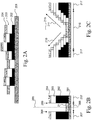
- Fig. 2B - 2G are cross cuts near a relief print area to be finished according to the method of the present invention.
- the number of layers in a relief part, a white part and a skin part are selected to be small for illustrating purposes and for convenience reasons. In practice a larger number of layers may be used.
- a number of pixels is printed comprising a relief part 202, a white part 203 and a skin part 204.
- a finishing action like a fold, crease, bending or cut is planned at a finishing line 205. It is noted that the finishing line 205 is actually extending perpendicular to the surface of the drawing.
- An area 206 to be finished and including and surrounding the finishing line 205 has a reduced pixel height in comparison to the pixel height in an area 207 not to be finished, but intended to be regularly printed.
- the pixels comprise the relief part 202, the white part 203 and the skin part 204.
- the pixels do not comprise a relief part 202 - or at least a relief part with a substantially reduced height (not shown) - and a white part 203, but only comprise a skin part 21 directly deposited on the substrate 201.
- the intended finishing action will not bend or cut the entire pixel column of the relief part 202, the white part 203, the skin part 204 and the substrate 201, but only the skin part 21 and the substrate 201 - and in another embodiment (not shown) a relief part reduced in height - at the area 206 to be finished.
- a transition in pixel height between the area 206 to be finished and the area 207 not to be finished is rather abrupt leading to vertical edges 208, 209 at the boundary between the area 206 to be finished and the area 207 not to be finished.
- Fig. 2C shows an example of the method wherein a transition in pixel height between an area 216 to be finished and an area 217 not to be finished is not abrupt but is smoothened. This is done by adapting the inking mask according to the method of the invention for smoothening edges near a finishing line 215 in the inking mask, wherein the inking mask comprises zones adjacent to the finishing line 215 with a gradually increasing relative height towards the areas 217 not to be finished. By doing so, the area 216 to be finished comprises the slopes 210, 211.
- a number of pixels is printed comprising a relief part 222, a white part 223 and a skin part 224.
- a finishing action like a fold, crease, bending or cut is planned at the finishing line 225.
- An area 226 to be finished and including and surrounding the finishing line 225 has a reduced pixel height in comparison to the pixel height in an area 227 not to be finished, but intended to be regularly printed.
- the pixels comprise the relief part 222, the white part 223 and the skin part 224.
- the pixels do not comprise a relief part 222 or comprises at least a relief part of a substantially reduced height, but do comprise a skin part 22 upon a white part 23 which is directly deposited on the substrate 221. By doing so, unwanted colour differences between the area 226 and the area 227 are reduced or eliminated.
- a transition in pixel height between the area 226 to be finished and the area 227 not to be finished is not abrupt but is smoothened. This is done by adapting the inking mask according to the method of the invention for smoothening edges near a finishing line 225 in the inking mask, wherein the inking mask comprises zones adjacent to the finishing line 225 with a gradually increasing relative height towards the areas 227 not to be finished. By doing so, the area 226 to be finished comprises the slopes 24, 25.
- the inking mask is adapted for smoothening the printed colours near the finishing line 225 in the inking mask, wherein the inking mask comprises zones B, A adjacent to the finishing line 225 with a gradually increasing number of layers of the white part towards the areas 227 not to be finished.
- a transition in pixel height between an area 236 to be finished and areas 237 not to be finished is not abrupt but is smoothened. This is done by adapting the inking mask according to the method of the invention for smoothening edges near a finishing line 235 in the inking mask, wherein the inking mask comprises zones adjacent to the finishing line 235 with a gradually increasing relative height towards the areas 237 not to be finished. By doing so, the area 236 to be finished comprises slopes 26, 27.
- the inking mask is also adapted for smoothening the printed colours near the finishing line 235 in the inking mask, wherein the inking mask comprises zones adjacent to the finishing line 235 with a gradually increasing number of layers of the white part from 1 white layer via 2 white layers in the area 236 to be finished towards 3 white layers in the areas 237 not to be finished.
- Fig. 3 shows an inking mask 300 for a book cover having four edges 38.
- the book cover is intended to be folded along to fold lines 31,32.
- Areas not to be finished are referenced to by reference numbers 371, 372, 373 and are grey coloured.
- Each pixel in the areas not to be finished 371, 372, 373 has a binary value 1 in the inking mask.
- Areas to be finished are referenced to by reference numbers 361, 362, 363 and are white coloured.
- the areas 361, 362, 363 to be finished comprise zones near the folding lines 31, 32.
- the areas 361, 362, 363 to be finished optionally comprise zones along the edges 38 of the inking mask.
- Each pixel in the areas 361, 362, 363 to be finished has a binary value 0 in the inking mask in the example corresponding to FIG. 2B .
- the relative height may also be termed height factor and may be multiplied with the height data of the corresponding pixels of the digital image in order to obtain the absolute height data for the printed digital image. Because the inking mask of this embodiment does not comprise sharp transitions from finishing to non-finishing areas, the edges of the finishing areas are smoothed and hence less visible and less vulnerable.
- An area 33 will be zoomed in at in Fig. 4 in order to explain height values of the inking mask in the area 33.
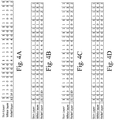
- Fig. 4A - 4D show height values in the area 33 shown in Fig. 3 .
- the height values are per part, i.e. the skin part, the white part and the relief part of the pixels from a left side of the area 33 to a right side of the area 33.
- a height value of the skin part is considered to be 1 layer.
- Other non-zero height values for the skin part may be envisioned.
- a regular height value for the white part in pixels in areas 371, 372, 373 not to be finished in Fig. 3 is considered to be 3 layers.
- Other non-zero height values for the white part of pixels in the areas 371, 372, 373 not to be finished may be envisioned.
- the height value of the relief part in the areas 361, 362, 363 to be finished in Fig. 3 is zero according to an embodiment of the method of the present invention. According to another embodiment of the method of the invention the height value of the relief part in the areas 361, 362, 363 to be finished is substantially reduced (not shown).
- the reduction of the height of the relief part in the areas 361, 362, 363 may be predetermined by a crack threshold when cracking of the substrate does not occur. In the latter case the height of the relief part is then substantially reduced to a non-zero height which is smaller than the originally planned height of the relief part.
- Fig. 4A corresponds to the method according to the invention as applied in Fig. 2B with steep edges between the areas 361, 362, 363 to be finished and the areas 371, 372, 373 not to be finished.
- Fig. 4B corresponds to the method according to the invention as applied in Fig. 2D with steep edges between the areas 361, 362, 363 to be finished and the areas 371, 372, 373 not to be finished but with colour preservation in the areas 361, 362, 363 to be finished due to the deposited white layer part in the areas 361, 362, 363 to be finished.
- Fig. 4C corresponds to the method according to the invention as applied in Fig. 2F with a smoothing of the colours in the areas 361, 362, 363 to be finished due to a gradually decrease of the numbers of white layers in the areas 361, 362, 363 to be finished.
- Fig. 4D corresponds to the method according to the invention as applied in Fig. 2G , wherein besides the smoothening of the white part in the areas 361, 362, 363 to be finished also the relief part is smoothened, for example from 10 layers on the left side of the area 33 in Fig. 3 via 5 layers to 1 layer of relief towards the first finishing line 32 in Fig. 3 .
- FIG. 5A shows an example of an inking mask for a book cover.
- the inking mask takes two fold lines and the edges of the book cover into account.
- Fig. 5B shows an example of an inking mask for a lid of a box.
- the inking mask takes fold lines (shown as ordinary lines), cut lines (shown as bold lines) as well as edges into account.
- the areas to be finished are white coloured and the areas not to be finished are grey coloured.
- FIG. 6A - 6C show a method step of determining a threshold for a height of a pixel for cracking at a finishing line and reducing the height of the relief part to a value below the threshold.
- Thresholds may be determined per type of finishing action, per ink type and/or per type of substrate. Thresholds may be predetermined by experiments with finishing actions, inks and substrates.
- a test set up may be folding a stroke of 2.5 cm of substrate 601 over an 180 degree's angle as shown in FIG. 6A.
- FIG. 6A (1) shows a flat substrate 601 with applied ink layers 602.
- FIG. 6A (2) shows the folded substrate with no cracking of the ink layers.
- FIG. 6A (3) shows the folded substrate with a cracking of the ink layers.
- the substrate 601 may be for example Oce Outdoor Paper 212 g/m 2 with a thickness of 230 ⁇ m but other substrates may be envisioned.
- FIG. 6B shows on the left side a book cover printed with an ink type a with a thickness of the ink layers of 20 ⁇ m without any crack.
- FIG. 6B shows in the middle a book cover printed with an ink type a with a thickness of the ink layers of 75 ⁇ m resulting in a crack of the ink layers such that a part of the substrate becomes visible.
- FIG. 6C shows on the right side a book cover printed with an ink type b with a thickness of the ink layers of 75 ⁇ m resulting in no crack of the ink layers.
- the threshold for ink type a may be determined to be equal to 30 ⁇ m.
- the threshold for ink type b may be determined to be larger than 75 ⁇ m.
- Ink type a and b may be for example Oce UV-Curable ink types but other ink types may be envisioned. Other kind of ink types, like more flexible inks may be envisioned.
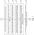
- Fig. 7 is a flow diagram of the method according to the invention. The method starts in a starting point A which leads to a first step S1.
- the digital image is provided comprising a raster of a plurality of pixels.
- the digital image comprises colour information for each pixel.
- a height channel is provided to the digital image defining a height for each pixel.
- the height has a minimum non-zero value.
- the first step S1 may be combined with the second step S2 when a digital image is received which besides colour information per pixel also comprises height values for the pixels.
- a relief part a white part and a skin part is discriminated.
- the parts constitute the height of the pixel.
- the relief part comprises an arbitrary colorant composition.
- the white part comprises a number of colorants including a white colorant.
- the skin part comprises colorants according to a colour as defined by the colour information for each pixel.
- an inking mask is provided which comprises a binary image of areas of the substrate to be finished and areas of the substrate not to be finished.
- a fifth step S5 the digital image is image processed by applying the inking mask to the image, wherein the height of a pixel within an area of the substrate to be finished is reduced to a non-zero height value and wherein the height of a pixel within an area of a substrate not to be finished is left unchanged.
- the non-zero height value is so small that no relief part or an in height reduced relief part is intended to be printed for the pixels in an area of the substrate to be finished and so large that at least the skin part is intended to be printed for the pixels in an area of the substrate to be finished. Examples of applicable non-zero height values in the areas to be finished are described here-above and shown in Fig. 4A - 4D .
- a sixth step S6 the image processed image obtained in the fifth step S5 is printed on the substrate.
- the method ends in an end point B.
- FIG. 8 is an alternative embodiment of the method according to the invention. According to this alternative embodiment the method comprises the steps of
- FIG. 8A shows an area 837 not to be finished wherein the hixx of the pixels is constant.
- FIG. 8B shows an area 837 not to be finished and an area 836 to be finished and surrounding a finishing line 835. The height of the pixels in the area 836 to be finished is substantially reduced in order to prevent cracking of the layers deposited on the substrate 801.
- the height of the pixels in the area 836 to be finished are stepwise decreased towards the finishing line 835.
- a transition in pixel height between an area 836 to be finished and areas 837 not to be finished is not abrupt but is smoothened. This is done by adapting the inking mask according to the method of the invention for smoothening edges near the finishing line 835 in the inking mask, wherein the inking mask comprises zones adjacent to the finishing line 835 with a gradually increasing relative height towards the areas 837 not to be finished.
- the area 836 to be finished comprises slopes 86, 87.
Landscapes
- Engineering & Computer Science (AREA)
- Textile Engineering (AREA)
- Multimedia (AREA)
- Signal Processing (AREA)
- Printing Methods (AREA)
- Ink Jet (AREA)
Abstract
Description
- The present invention relates to a method of printing for producing objects by additive manufacturing.
- Additive manufacturing techniques using ink-jet technology are known in the art, for example from US patent publication
US2015/144014 , wherein a method for generating relief prints is disclosed. Ink-jet technology creates a solid ink layer on top of a substrate. When multiple layers are printed textured structures can be created. A solid ink layer tends to crack, break or chip during finishing after printing like folding, bending, creasing or cutting. Finishing by finishing lines, for example cut paths, folding patterns, etc., may be specified in print job specifications of a print job for printing a relief print. The solid ink layer comprises three parts: a relief part, a white part and a coloured skin part. The relief part is deposited on the substrate and covered with a white part to be able to print in full colour. The white part is covered with the coloured skin part. - For the term "substrate" also the term "media" will be used hereinafter.
- Finishing a print job is not meant as completing a print job but as executing finishing actions - post processing steps - by finishing equipment as specified in print job specifications.
- Modern UV ink formulations create a more flexible solid ink layer to prevent cracking. However, when multiple ink layers are printed to create a textured print a total ink package becomes more stiff and brittle, and thus cracking will occur. Besides this, flexible ink formulations are less suitable for textured multiplayer printing.
- The known methods relate to single object manufacturing. If one desires to fold the printed object, to crease the printed object, to bend the printed object or to cut the printed object, there is a significant risk of damaging the printed object.
- Another problem qua colours of cutting edges arises when cutting a textured print. The height sides along the cut line may show the relief and the white part according to the colours of the relief and white parts for the pixels at the location of the cut line which may differ from the colours of the colour part for the pixels at the location of the cut line.
- It is therefore an object of the present invention to overcome or at least mitigate said disadvantages and provide a method of printing for directly manufacturing the intended object which can be finished after printing, i.e. folded, creased, bended or cut with elimination of the risk of damaging the printed object due to the folding, creasing, bending or cutting and with elimination of the above-mentioned cutting edge colour problem.
- This object can be obtained with a printing method for printing a digital image on a substantially flat substrate, the printing method comprising the steps of
- a) providing the digital image comprising a raster of a plurality of pixels, the digital image comprising colour information for each pixel,
- b) providing a height channel to the digital image defining a height for each pixel, the height having a minimum value,
- c) discriminating in the digital image for each pixel a relief part, a white part and a skin part, the parts constituting the height of the pixel and the relief part comprising an arbitrary colorant composition, the white part comprising a number of colorants including a white colorant and the skin part comprising colorants according to a colour as defined by the colour information for each pixel,
- d) providing an inking mask comprising a binary image of areas of the substrate intended to be finished after printing and areas of the substrate not intended to be finished after printing;
- e) image processing of the digital image by applying the inking mask to the image, wherein the height of a pixel within an area of the substrate intended to be finished after printing is reduced by substantially reducing a height of the relief part of said pixel, and wherein the height of a pixel within an area of a substrate not intended to be finished after printing is left unchanged, and
- f) printing the processed image obtained in step e) on the substrate.
- According to an embodiment the height value of each pixel in the area of the substrate intended to be finished after printing is so large that at least the skin part is intended to be printed. By doing so, the coloured image is still visible in the substrate area intended to be finished after printing.
- According to an embodiment the height value of each pixel in the area of the substrate to be finished after printing is so small that no relief part is intended to be printed. By printing no relief part, the height is reduced to the at least the skin part and the white part in order to minimize a chance on cracking of the ink layers in the substrate areaintended to be finished after printing.
- The finishing action in the area intended to be finished is at least one out of a fold, a crease, a bending and a cut of the substrate. The areas of the substrate intended to be finished are including and surrounding finishing lines like fold lines, crease lines, bend lines and/or cut lines. The finishing lines may be curved. In the areas intended to be finished the digital image is printed according to the colour information per pixel provided in step a), but not according to the height information per pixel provided in step b). In the areas intended to be finished the digital image has been image processed according to step e) before the printing step f).
- According to a further embodiment the method comprising the step of finishing by means of finishing equipment the processed image in step f) in the areas intended to be finished. The finishing equipment may be at least one out of a folder, a creaser, a bender, a puncher, a stapler and a cutter.
- In the areas not intended to be finished the digital image is printed according to the provided colour information per pixel as well as according to the provided height information per pixel.
- By doing so, the method according to the present invention has full control with respect to the applied inking mask, e.g. a number, a size and a width of the fold, crease, bending or cut lines can be completely controlled dependent on the desired application, by defining the inking mask.
- According to a further embodiment the area intended to be finished comprises an edge of the substrate. Near an edge of a substrate the relief may be reduced to zero according to the invention. This is advantageous, since by doing so the edges are less vulnerable for damage.
- It is advantageous of the method according to the invention that the colour information at the area intended to be finished is not lost, such that a complete colour image intended to cover the whole area intended to be finished is printed.
- In the method according to the present invention a printing technique that is suitable for additive manufacturing and/or capable of forming an image (picture) can be used. An example of such a printing technique is ink jetting a radiation curable, e.g. UV-curable, ink composition. In such printing technique (known in the art) a layer of liquid ink is applied to the surface of a substrate (which may also be a previously formed ink layer), by expelling ink droplets from an ink jet imaging device. After impact on the surface of said substrate, the liquid ink is radiated (e.g. with UV-radiation from a UV-lamp or UV-LED) to start a polymerization reaction of the reactive components in the ink composition to cure the ink.
- In an embodiment, the digital image comprises a 2D image not containing height information for the pixels (step a), wherein the image processing step (step e) comprises appending height information to the raster of pixels located in the areas to be printed, preferably in accordance with the desired thickness of the printed image.
- In an embodiment, the digital image comprises a 3D (relief) image containing height information of the pixels (step b), wherein the digital image comprises a 3D (relief) image containing height information of the pixels (step b).
- According to a further embodiment the height value for a pixel in the area of the substrate intended to be finished is so large that at least the skin part and at least one layer of the white part are intended to be printed. By doing so, colours in the areas intended to be finished are less different than or even equal to the colours in the areas not intended to be finished in contrast to a situation wherein no white part layers are printed.
- According to an embodiment the inking mask is adapted for smoothening an image region adjacent to the finishing lines in the inking mask, wherein the image region comprises zones adjacent to the finishing lines with a gradually increasing relative height towards the areas not intended to be finished.
The inking mask may comprise more than two (binary) inking levels, e.g. the inking mask comprises zones adjacent to the finishing lines with a gradually increasing relative height (from 0 to 1) towards the areas not intended to be finished (relative height =1). The relative height may also be termed height factor and may be multiplied with the height data of the corresponding pixels of the digital image in order to obtain the absolute height data for the printed digital image. Because the inking mask of the present embodiment does not comprise sharp transitions from finishing to non-finishing areas, the image region adjacent to the finishing lines are smoothed and the transition from finishing to non-finishing areas are hence less visible and less vulnerable. - According to an embodiment the inking mask is adapted for smoothening the printed colours near the finishing lines in the inking mask, wherein the inking mask comprises zones adjacent to the finishing lines with a gradually increasing number of layers of the white part towards the areas not intended to be finished.
- According to an embodiment the method comprises the steps of reducing of the height of the relief part in the areas intended to be finished according to a height threshold per type of finishing action such that the height of the relief part in an area intended to be finished is substantially reduced to a non-zero height which is smaller than the height threshold corresponding to the type of finishing action defined for said area intended to be finished.
By doing so, the method comprises the steps of determining a threshold for a height of a pixel for cracking at a finishing line and reducing the height of the relief part to a value below the threshold. The threshold may be determined per type of finishing action. The threshold may be determined per type of substrate. The threshold may be determined per type of ink. The threshold may be predetermined by experiments with combinations of finishing actions, inks and substrates. - The invention also relates to a printing method for printing a digital image on a substantially flat substrate, the printing method comprising the steps of
- a) providing the digital image comprising a raster of a plurality of pixels, the digital image comprising colour information for each pixel,
- b) providing a height channel to the digital image defining a height for each pixel, the height having a minimum value,
- c) discriminating in the digital image for each pixel a transparent relief part on top of a colour part, the parts constituting the height of the pixel and the relief part comprising an arbitrary transparent colorant composition and the colour part comprising colorants according to a colour as defined by the colour information for each pixel,
- d) providing an inking mask comprising a binary image of areas of the substrate intended to be finished after printing and areas of the substrate not intended to be finished after printing,
- e) image processing of the digital image by applying the inking mask to the image, wherein the height of a pixel within an area of the substrate intended to be finished after printing is reduced by substantially reducing a height of the transparent relief part of said pixel, and wherein the height of a pixel within an area of a substrate not intended to be finished after printing is left unchanged, and
- f) printing the processed image obtained in step e) on the substrate.
- The invention is also related to a printed object obtained with a method according to the invention. The printed object may be a book cover, a box, a box lid, wall paper, etc.
- The invention also relates to a printer comprising a controller configured for performing a method according to the invention.
- According to a further embodiment the controller of the printer is configured to generate an inking mask comprising a binary image of areas to be finished and areas not to be finished. The inking mask preferably comprises areas intended to be finished with finishing lines.
- In an embodiment, the controller comprises a user interface for entering input data based on which the controller generates the inking mask.
- The invention also relates to a software product comprising program code on a non-transitory computer-readable medium, wherein said program code, when loaded into a computer that is connected to a printer causes the computer to perform the method according to the invention.
- The present invention will become more fully understood from the detailed description given herein below and accompanying schematic drawings which are given by way of illustration only and are not limitative of the invention, and wherein:
-
Fig. 1 shows a schematic representation of a printer according to the present invention; -
Fig. 2A shows a cross cut of a printed digital image according to the prior art; -
Fig. 2B - 2G schematically show cross cuts of a printed digital image near an area to be finished and printed according to the method of the present invention; -
Fig. 3 schematically shows an example of an inking mask used in image processing for a book cover according to the present invention; -
Fig. 4A - 4D show examples of height values after image processing the digital image with a inking mask and reducing the height values in an area to be finished according to the method of the present invention; and -
Fig. 5A - 5B show examples of inking masks for a book cover and for a box lid respectively; -
FIG. 6A - 6C show a method step of determining a threshold for a height of a pixel for cracking at a finishing line; -
Fig. 7 is a flow diagram of the method according to the present invention; and -
FIG. 8A - 8B is an alternative embodiment of the method according to the invention. -
Fig. 1 shows a schematic representation of aprinter 5 according to the present invention. Theprinter 5 is configured to print a relief image on standard media or on thick media. -
Fig. 1 shows aprinter 5 comprising a number ofworkstations print controller 8A that is configured to receive print jobs for prints and derive pass images for ink layers of the relief print. Theprint controller 8A may be part of theprinter 5 that further comprises aprint head 2 for applying colorants, for example cyan (C), magenta (M), yellow (Y), black (K) and white (W) colorant but other colours may be provided, or varnish, to amedia object 9 placed on aflat bed surface 1 in order to obtain a printed relief image on themedia object 9. Theflat bed surface 1 is the surface of the flat bed which is at least partially printable by theprint head 2. It is noted that the media object may be of an arbitrary shape and at an arbitrary position on theflat bed surface 1. The media object may be so small that it is completely placed on theflat bed surface 1 and has a height that is convenient for the perpendicular distance of theprint head 2 to theflat bed surface 1. Themedia object 9, i.e. a book cover material, may be provided with any recording material or not yet. Theprint head 2 reciprocally scans theflat bed surface 1 in the second direction X along agantry 7 perpendicular to a first direction Y of thegantry 7 over theflat bed surface 1 along guidingparts 10. During printing of a relief image on themedia object 9 themedia object 9 is not moved on theflat bed surface 1. This way of working is advantageous for rigid media objects. A material of themedia object 9 may be paper, wood, glass, plexiglass, plastic, board, textile, etc. A print head which is as wide as the flat bed surface may also be envisaged within the scope of the invention. Such a print head may be moveable in at least one direction over theflat bed surface 1. A print head which is not moveable such that the substrate is moved multiple times under the print head may also be envisioned to fall under the scope of the invention. - The printer comprises a user interface which, in this embodiment, is integrated in
printer controller 8A for selecting a print job and optionally adapting a print job parameter, such as a print mode which controls the number of passes over a given swath on the media object. In another embodiment a user interface is provided as a network site that is accessible with a browser on a client computer. - The present invention consists in using an additive manufacturing printer (
flat bed printer 5 or a 3D printer) for printing objects, in the present example abook cover material 9 is going to be printed upon. Basically the invention lies in the fact that in the additive manufacturing technique the image is processed such that thefinishing lines finishing lines finishing lines Such finishing lines printer 5 may be executed by a finishing device (not shown) placed near theprinter 5. - It is advantageous of the method according to the invention that the colour information at the areas to be finished is not lost, such that a complete colour image covering the whole areas to be finished is printed.
- A book cover pattern can be provided as a so called 'inking mask', which basically is a binary mask indicating areas to be finished and areas not to be finished. The inking mask can be (digitally) applied to the image to be printed, to obtain a processed digital image. In case of a book cover pattern, the finishing lines are indicated as areas to be finished (black). If required the width of the finishing lines may be adapted in the inking mask depending on the kind of folding, creasing, bending or cutting action.
- Therefore, in case of relief printing a book cover, a box, a box lid or wall paper, the finishing lines are not only used for defining the finishing shape of the folding, creasing, bending or cut machine, but are used to finish the printed image such that material deposition can be controlled in such a way that areas to be finished of the book cover, the box, the box lid or the wall paper are obtained automatically during printing.
-
Fig. 2A is a cross cut of a relief print according to the prior art. On a substrate 201 a number of pixels is printed comprising arelief part 202, awhite part 203 and askin part 204. The height variation of the individual pixels on theflat substrate 201 is caused by repetitive printing of colorants in therelief part 202 or by repetitive printing of substances other than colorants which substances may be cheaper. All available colorants, inks, transparent or resins without colour may be used in the relief part, which provides for an optimal print speed for this part. Thewhite part 203 is printed on top of therelief part 202 to conceal the colorants used therein and to provide a standard white background for the colorants in theskin part 204. The combination of colorants in the skin part is generated from a color management module that is calibrated for prints using the color channels of a rasterized digital image. Note that a predetermined thickness for the white part of the pixels is used, determined by the opacity of the white ink, which results in a background that is the same for all pixels. -
Fig. 2B - 2G are cross cuts near a relief print area to be finished according to the method of the present invention. The number of layers in a relief part, a white part and a skin part are selected to be small for illustrating purposes and for convenience reasons. In practice a larger number of layers may be used. - In
Fig. 2B on a substrate 201 a number of pixels is printed comprising arelief part 202, awhite part 203 and askin part 204. A finishing action like a fold, crease, bending or cut is planned at afinishing line 205. It is noted that thefinishing line 205 is actually extending perpendicular to the surface of the drawing. Anarea 206 to be finished and including and surrounding thefinishing line 205 has a reduced pixel height in comparison to the pixel height in anarea 207 not to be finished, but intended to be regularly printed. At thearea 207 not to be finished the pixels comprise therelief part 202, thewhite part 203 and theskin part 204. At thearea 206 to be finished the pixels do not comprise a relief part 202 - or at least a relief part with a substantially reduced height (not shown) - and awhite part 203, but only comprise a skin part 21 directly deposited on thesubstrate 201.
By doing so, the intended finishing action will not bend or cut the entire pixel column of therelief part 202, thewhite part 203, theskin part 204 and thesubstrate 201, but only the skin part 21 and the substrate 201 - and in another embodiment (not shown) a relief part reduced in height - at thearea 206 to be finished.
In the example inFig. 2B a transition in pixel height between thearea 206 to be finished and thearea 207 not to be finished is rather abrupt leading tovertical edges area 206 to be finished and thearea 207 not to be finished. -
Fig. 2C shows an example of the method wherein a transition in pixel height between anarea 216 to be finished and anarea 217 not to be finished is not abrupt but is smoothened. This is done by adapting the inking mask according to the method of the invention for smoothening edges near afinishing line 215 in the inking mask, wherein the inking mask comprises zones adjacent to thefinishing line 215 with a gradually increasing relative height towards theareas 217 not to be finished. By doing so, thearea 216 to be finished comprises theslopes - In
Fig. 2D on a substrate 221 a number of pixels is printed comprising arelief part 222, awhite part 223 and askin part 224. A finishing action like a fold, crease, bending or cut is planned at thefinishing line 225. Anarea 226 to be finished and including and surrounding thefinishing line 225 has a reduced pixel height in comparison to the pixel height in anarea 227 not to be finished, but intended to be regularly printed. At thearea 227 not to be finished the pixels comprise therelief part 222, thewhite part 223 and theskin part 224. At thearea 226 to be finished the pixels do not comprise arelief part 222 or comprises at least a relief part of a substantially reduced height, but do comprise askin part 22 upon a white part 23 which is directly deposited on thesubstrate 221. By doing so, unwanted colour differences between thearea 226 and thearea 227 are reduced or eliminated. - To avoid the steep edges between the
area 226 and thearea 227, inFIG. 2E a transition in pixel height between thearea 226 to be finished and thearea 227 not to be finished is not abrupt but is smoothened. This is done by adapting the inking mask according to the method of the invention for smoothening edges near afinishing line 225 in the inking mask, wherein the inking mask comprises zones adjacent to thefinishing line 225 with a gradually increasing relative height towards theareas 227 not to be finished. By doing so, thearea 226 to be finished comprises theslopes - In
Fig. 2F the inking mask is adapted for smoothening the printed colours near thefinishing line 225 in the inking mask, wherein the inking mask comprises zones B, A adjacent to thefinishing line 225 with a gradually increasing number of layers of the white part towards theareas 227 not to be finished. - In
Fig. 2G a transition in pixel height between anarea 236 to be finished andareas 237 not to be finished is not abrupt but is smoothened. This is done by adapting the inking mask according to the method of the invention for smoothening edges near afinishing line 235 in the inking mask, wherein the inking mask comprises zones adjacent to thefinishing line 235 with a gradually increasing relative height towards theareas 237 not to be finished. By doing so, thearea 236 to be finished comprisesslopes
InFig. 2G the inking mask is also adapted for smoothening the printed colours near thefinishing line 235 in the inking mask, wherein the inking mask comprises zones adjacent to thefinishing line 235 with a gradually increasing number of layers of the white part from 1 white layer via 2 white layers in thearea 236 to be finished towards 3 white layers in theareas 237 not to be finished. -
Fig. 3 shows an inkingmask 300 for a book cover having fouredges 38. The book cover is intended to be folded along to foldlines
Areas not to be finished are referenced to byreference numbers binary value 1 in the inking mask.
Areas to be finished are referenced to byreference numbers
white coloured. Theareas folding lines areas edges 38 of the inking mask. Each pixel in theareas binary value 0 in the inking mask in the example corresponding toFIG. 2B . - According to another embodiment the inking mask comprises more than two (binary) inking levels, e.g. the inking mask comprises zones adjacent to the finishing lines with a gradually increasing relative height (from 0 to 1) towards the areas not to be finished (relative height =1). The relative height may also be termed height factor and may be multiplied with the height data of the corresponding pixels of the digital image in order to obtain the absolute height data for the printed digital image. Because the inking mask of this embodiment does not comprise sharp transitions from finishing to non-finishing areas, the edges of the finishing areas are smoothed and hence less visible and less vulnerable.
- An
area 33 will be zoomed in at inFig. 4 in order to explain height values of the inking mask in thearea 33. -
Fig. 4A - 4D show height values in thearea 33 shown inFig. 3 . The height values are per part, i.e. the skin part, the white part and the relief part of the pixels from a left side of thearea 33 to a right side of thearea 33. For convenience reasons, a height value of the skin part is considered to be 1 layer. Other non-zero height values for the skin part may be envisioned. For convenience reasons, a regular height value for the white part in pixels inareas Fig. 3 is considered to be 3 layers. Other non-zero height values for the white part of pixels in theareas areas Fig. 3 is zero according to an embodiment of the method of the present invention. According to another embodiment of the method of the invention the height value of the relief part in theareas areas -
Fig. 4A corresponds to the method according to the invention as applied inFig. 2B with steep edges between theareas areas
Fig. 4B corresponds to the method according to the invention as applied inFig. 2D with steep edges between theareas areas areas areas -
Fig. 4C corresponds to the method according to the invention as applied inFig. 2F with a smoothing of the colours in theareas areas
Fig. 4D corresponds to the method according to the invention as applied inFig. 2G , wherein besides the smoothening of the white part in theareas area 33 inFig. 3 via 5 layers to 1 layer of relief towards thefirst finishing line 32 inFig. 3 . -
FIG. 5A shows an example of an inking mask for a book cover. The inking mask takes two fold lines and the edges of the book cover into account.
Fig. 5B shows an example of an inking mask for a lid of a box. The inking mask takes fold lines (shown as ordinary lines), cut lines (shown as bold lines) as well as edges into account.
InFig. 5A-5B the areas to be finished are white coloured and the areas not to be finished are grey coloured. -
FIG. 6A - 6C show a method step of determining a threshold for a height of a pixel for cracking at a finishing line and reducing the height of the relief part to a value below the threshold. Thresholds may be determined per type of finishing action, per ink type and/or per type of substrate. Thresholds may be predetermined by experiments with finishing actions, inks and substrates.
A test set up may be folding a stroke of 2.5 cm ofsubstrate 601 over an 180 degree's angle as shown inFIG. 6A. FIG. 6A (1) shows aflat substrate 601 with applied ink layers 602.FIG. 6A (2) shows the folded substrate with no cracking of the ink layers.FIG. 6A (3) shows the folded substrate with a cracking of the ink layers. Thesubstrate 601 may be for example Oce Outdoor Paper 212 g/m2 with a thickness of 230 µm but other substrates may be envisioned.
FIG. 6B shows on the left side a book cover printed with an ink type a with a thickness of the ink layers of 20 µm without any crack.FIG. 6B shows in the middle a book cover printed with an ink type a with a thickness of the ink layers of 75 µm resulting in a crack of the ink layers such that a part of the substrate becomes visible.FIG. 6C shows on the right side a book cover printed with an ink type b with a thickness of the ink layers of 75 µm resulting in no crack of the ink layers.
FIG. 6C show results of a small experiment for the ink type a and the ink type b. The threshold for ink type a may be determined to be equal to 30 µm. The threshold for ink type b may be determined to be larger than 75 µm. Ink type a and b may be for example Oce UV-Curable ink types but other ink types may be envisioned. Other kind of ink types, like more flexible inks may be envisioned. -
Fig. 7 is a flow diagram of the method according to the invention.
The method starts in a starting point A which leads to a first step S1. - In the first step S1 the digital image is provided comprising a raster of a plurality of pixels. The digital image comprises colour information for each pixel.
- In a second step S2 a height channel is provided to the digital image defining a height for each pixel. The height has a minimum non-zero value.
The first step S1 may be combined with the second step S2 when a digital image is received which besides colour information per pixel also comprises height values for the pixels. - In a third step S3 for each pixel in the digital image a relief part, a white part and a skin part is discriminated. The parts constitute the height of the pixel. The relief part comprises an arbitrary colorant composition. The white part comprises a number of colorants including a white colorant. The skin part comprises colorants according to a colour as defined by the colour information for each pixel.
- In a fourth step S4 an inking mask is provided which comprises a binary image of areas of the substrate to be finished and areas of the substrate not to be finished.
- In a fifth step S5 the digital image is image processed by applying the inking mask to the image, wherein the height of a pixel within an area of the substrate to be finished is reduced to a non-zero height value and wherein the height of a pixel within an area of a substrate not to be finished is left unchanged. The non-zero height value is so small that no relief part or an in height reduced relief part is intended to be printed for the pixels in an area of the substrate to be finished and so large that at least the skin part is intended to be printed for the pixels in an area of the substrate to be finished. Examples of applicable non-zero height values in the areas to be finished are described here-above and shown in
Fig. 4A - 4D . - In a sixth step S6 the image processed image obtained in the fifth step S5 is printed on the substrate. The method ends in an end point B.
-
FIG. 8 is an alternative embodiment of the method according to the invention. According to this alternative embodiment the method comprises the steps of - a) providing the digital image comprising a raster of a plurality of pixels, the digital image comprising colour information for each pixel,
- b) providing a height channel to the digital image defining a height for each pixel, the height having a minimum value,
- c) discriminating in the digital image for each pixel a transparent relief part on top of a colour part, the parts constituting the height of the pixel and the relief part comprising an arbitrary transparent colorant composition and the colour part comprising colorants according to a colour as defined by the colour information for each pixel,
- d) providing an inking mask comprising a binary image of areas of the substrate to be finished and areas of the substrate not to be finished,
- e) image processing of the digital image by applying the inking mask to the image, wherein the height of a pixel within an area of the substrate to be finished is reduced by substantially reducing a height of the transparent relief part of said pixel, and wherein the height of a pixel within an area of a substrate not to be finished is left unchanged, and
- f) printing the processed image obtained in step e) on the substrate.
- This embodiment is illustrated by cross cuts of the printed layers in
FIG. 8A - 8B . Acolour part 804 is directly deposited on asubstrate 801. Upon the colour part 804 atransparent relief part 802 of multiple layers is deposited. Thetransparent relief part 802 may consist of a transparent ink, a varnish, or any other transparent printable material.FIG. 8A shows anarea 837 not to be finished wherein the higeht of the pixels is constant.FIG. 8B shows anarea 837 not to be finished and anarea 836 to be finished and surrounding afinishing line 835. The height of the pixels in thearea 836 to be finished is substantially reduced in order to prevent cracking of the layers deposited on thesubstrate 801. The height of the pixels in thearea 836 to be finished are stepwise decreased towards thefinishing line 835. A transition in pixel height between anarea 836 to be finished andareas 837 not to be finished is not abrupt but is smoothened. This is done by adapting the inking mask according to the method of the invention for smoothening edges near thefinishing line 835 in the inking mask, wherein the inking mask comprises zones adjacent to thefinishing line 835 with a gradually increasing relative height towards theareas 837 not to be finished. By doing so, thearea 836 to be finished comprisesslopes - Detailed embodiments of the present invention are disclosed herein; however, it is to be understood that the disclosed embodiments are merely exemplary of the invention, which can be embodied in various forms. Therefore, specific structural and functional details disclosed herein are not to be interpreted as limiting, but merely as a basis for the claims and as a representative basis for teaching one skilled in the art to variously employ the present invention in virtually any appropriately detailed structure. In particular, features presented and described in separate dependent claims may be applied in combination and any advantageous combination of such claims is herewith disclosed.
- Further, the terms and phrases used herein are not intended to be limiting; but rather, to provide an understandable description of the invention. The terms "a" or "an", as used herein, are defined as one or more than one.
- The invention being thus described, it will be obvious that the same may be varied in many ways. Such variations are not to be regarded as a departure from the scope of the invention, and all such modifications as would be obvious to one skilled in the art are intended to be included within the scope of the following claims.
Claims (14)
- A printing method for printing a digital image on a substantially flat substrate, the printing method comprising the steps ofa) providing the digital image comprising a raster of a plurality of pixels, the digital image comprising colour information for each pixel,b) providing a height channel to the digital image defining a height for each pixel, the height having a minimum value,c) discriminating in the digital image for each pixel a relief part, a white part and a skin part, the parts constituting the height of the pixel and the relief part comprising an arbitrary colorant composition, the white part comprising a number of colorants including a white colorant and the skin part comprising colorants according to a colour as defined by the colour information for each pixel,d) providing an inking mask comprising a binary image of areas of the substrate intended to be finished after printing and areas of the substrate not intended to be finished after printing,e) image processing of the digital image by applying the inking mask to the image, wherein the height of a pixel within an area of the substrate intended to be finished after printing is reduced by substantially reducing a height of the relief part of said pixel, and wherein the height of a pixel within an area of a substrate not intended to be finished after printing is left unchanged, andf) printing the processed image obtained in step e) on the substrate.
- A printing method according to claim 1, wherein the height value of each pixel in the area of the substrate intended to be finished after printing is so large that at least the skin part is intended to be printed.
- A printing method according to claim 2, wherein the height value of each pixel in the area of the substrate intended to be finished after printing is so small that no relief part is intended to be printed.
- The printing method according to any of the preceding claims, wherein a finishing action in the area intended to be finished after printing is at least one out of a fold, a crease, a bending and a cut of the substrate.
- The printing method according to any of the preceding claims, wherein the area intedned to be finished after printing comprises an edge of the substrate.
- The printing method according to any of the preceding claims, wherein the areas of the substrate intended to be finished after printing are including and surrounding finishing lines like fold lines, crease lines, bending lines and/or cut lines.
- The printing method according to any of the claims 2 - 6, wherein the height value for a pixel in the area of the substrate intended to be finished after printing is so large that at least the skin part and at least one layer of the white part are intended to be printed.
- The method according to any of the claims 4 - 6, wherein the inking mask is adapted for smoothening an image region adjacent to the finishing lines in the inking mask, wherein the image region comprises zones adjacent to the finishing lines with a gradually increasing relative height towards the areas not intended to be finished after printing.
- The method according to any of the claims 4 - 8, wherein the inking mask is adapted for smoothening the printed colours near the finishing lines in the inking mask, wherein the inking mask comprises zones adjacent to the finishing lines with a gradually increasing number of layers of the white part towards the areas not intended to be finished after printing.
- The method according to any of the preceding claims, wherein the method comprises the steps of reducing of the height of the relief part in the areas intended to be finished after printing according to a height threshold per type of finishing action such that the height of the relief part in an area intended to be finished after printing is substantially reduced to a non-zero height which is smaller than the height threshold corresponding to the type of finishing action defined for said area intended to be finished after printing.
- The method according to any of the preceding claims, wherein the processed image printed in step f) is a book cover, a box, a box lid or wall paper.
- A printer comprising a controller configured for performing a method according to any one of claims 1 - 11.
- The printer according to claim 12, wherein the controller is configured to generate an inking mask comprising a binary image of areas intended to be finished and areas not intended to be finished.
- A software product comprising program code on a non-transitory computer-readable medium, wherein said program code, when loaded into a computer that is connected to a printer causes the computer to perform the method according to any of the claims 1 - 11.
Applications Claiming Priority (1)
| Application Number | Priority Date | Filing Date | Title |
|---|---|---|---|
| EP17173740 | 2017-05-31 |
Publications (2)
| Publication Number | Publication Date |
|---|---|
| EP3409494A1 true EP3409494A1 (en) | 2018-12-05 |
| EP3409494B1 EP3409494B1 (en) | 2021-07-07 |
Family
ID=59034443
Family Applications (1)
| Application Number | Title | Priority Date | Filing Date |
|---|---|---|---|
| EP18174104.2A Active EP3409494B1 (en) | 2017-05-31 | 2018-05-24 | Method of relief printing and a relief printer and a software product |
Country Status (2)
| Country | Link |
|---|---|
| US (1) | US10471730B2 (en) |
| EP (1) | EP3409494B1 (en) |
Families Citing this family (2)
| Publication number | Priority date | Publication date | Assignee | Title |
|---|---|---|---|---|
| WO2019124137A1 (en) * | 2017-12-19 | 2019-06-27 | キヤノン株式会社 | Image processing device, image processing method, and program |
| EP3809255A1 (en) * | 2019-10-16 | 2021-04-21 | Heidelberger Druckmaschinen AG | Special rasterizing pattern at folding edge |
Citations (3)
| Publication number | Priority date | Publication date | Assignee | Title |
|---|---|---|---|---|
| EP2672692A2 (en) * | 2012-06-08 | 2013-12-11 | Océ-Technologies B.V. | Method for generating relief prints |
| US20160193823A1 (en) * | 2015-01-05 | 2016-07-07 | Oce-Technologies B.V. | Method for generating relief prints |
| US20160318258A1 (en) * | 2015-04-29 | 2016-11-03 | Oce-Technologies B.V. | Method of printing an object having a surface of varying height |
-
2018
- 2018-05-23 US US15/987,248 patent/US10471730B2/en active Active
- 2018-05-24 EP EP18174104.2A patent/EP3409494B1/en active Active
Patent Citations (4)
| Publication number | Priority date | Publication date | Assignee | Title |
|---|---|---|---|---|
| EP2672692A2 (en) * | 2012-06-08 | 2013-12-11 | Océ-Technologies B.V. | Method for generating relief prints |
| US20150144014A1 (en) | 2012-06-08 | 2015-05-28 | Oce-Technologies B.V. | Method for generating relief prints |
| US20160193823A1 (en) * | 2015-01-05 | 2016-07-07 | Oce-Technologies B.V. | Method for generating relief prints |
| US20160318258A1 (en) * | 2015-04-29 | 2016-11-03 | Oce-Technologies B.V. | Method of printing an object having a surface of varying height |
Also Published As
| Publication number | Publication date |
|---|---|
| US20180345681A1 (en) | 2018-12-06 |
| EP3409494B1 (en) | 2021-07-07 |
| US10471730B2 (en) | 2019-11-12 |
Similar Documents
| Publication | Publication Date | Title |
|---|---|---|
| EP3439280A1 (en) | Object shaping method and object shaping system | |
| DE69702805T2 (en) | Versatile scaling of drawings | |
| US10429821B2 (en) | Method for printing colored object of 3D printer | |
| DE102015120241A1 (en) | Hybrid Printed Distorted Vector / Bitmap Security Feature | |
| EP3409494B1 (en) | Method of relief printing and a relief printer and a software product | |
| US9272528B2 (en) | Image processing device and method expanding aquired image data into printing data corresponding to a multi-layer image with color values less than or equal to a maximum ink amount | |
| JP6726191B2 (en) | Method for printing a print job on a medium in a flatbed printer and a flatbed printer | |
| DE102004015016A1 (en) | System for restricting user requests to print data | |
| US7511855B2 (en) | Systems and methods for reducing edge effects | |
| JP4469184B2 (en) | Method and apparatus for processing an image having a color combination | |
| JP7345977B2 (en) | Printing device and printing method | |
| US9387701B2 (en) | Method for generating relief prints | |
| EP3254828A1 (en) | Printing system and method for printing an object with a pattern on a surface of the object | |
| EP2908288B1 (en) | Vector data processor, image recording system, vector data processing method, and computer-readable medium | |
| JP2021045913A (en) | Printing equipment and printing method | |
| JP2014141026A (en) | Ink jet recording device and method of the same | |
| JP7119505B2 (en) | LIQUID EJECTING DEVICE AND LIQUID EJECTING METHOD | |
| US11449723B2 (en) | Method of printing an object having a surface of varying height | |
| EP3869319B1 (en) | Method and flatbed printer for printing print jobs on media pieces placeable on a flatbed of the flatbed printer | |
| JP2025114916A (en) | 3D modeling data creation device and method, and 3D modeling system | |
| JP7182493B2 (en) | Printing system and printing method | |
| US12141632B2 (en) | Printer control system, printing system, printing data creation method, and printing method | |
| JP5729423B2 (en) | Printing device | |
| EP3211875A1 (en) | Method of printing | |
| CN112659774A (en) | Grid structure of folding edge |
Legal Events
| Date | Code | Title | Description |
|---|---|---|---|
| PUAI | Public reference made under article 153(3) epc to a published international application that has entered the european phase |
Free format text: ORIGINAL CODE: 0009012 |
|
| STAA | Information on the status of an ep patent application or granted ep patent |
Free format text: STATUS: THE APPLICATION HAS BEEN PUBLISHED |
|
| AK | Designated contracting states |
Kind code of ref document: A1 Designated state(s): AL AT BE BG CH CY CZ DE DK EE ES FI FR GB GR HR HU IE IS IT LI LT LU LV MC MK MT NL NO PL PT RO RS SE SI SK SM TR |
|
| AX | Request for extension of the european patent |
Extension state: BA ME |
|
| STAA | Information on the status of an ep patent application or granted ep patent |
Free format text: STATUS: REQUEST FOR EXAMINATION WAS MADE |
|
| 17P | Request for examination filed |
Effective date: 20190605 |
|
| RBV | Designated contracting states (corrected) |
Designated state(s): AL AT BE BG CH CY CZ DE DK EE ES FI FR GB GR HR HU IE IS IT LI LT LU LV MC MK MT NL NO PL PT RO RS SE SI SK SM TR |
|
| RAP1 | Party data changed (applicant data changed or rights of an application transferred) |
Owner name: CANON PRODUCTION PRINTING HOLDING B.V. |
|
| RAP1 | Party data changed (applicant data changed or rights of an application transferred) |
Owner name: CANON PRODUCTION PRINTING HOLDING B.V. |
|
| REG | Reference to a national code |
Ref country code: DE Ref legal event code: R079 Ref document number: 602018019574 Country of ref document: DE Free format text: PREVIOUS MAIN CLASS: B41M0001100000 Ipc: H04N0001540000 |
|
| GRAP | Despatch of communication of intention to grant a patent |
Free format text: ORIGINAL CODE: EPIDOSNIGR1 |
|
| RIC1 | Information provided on ipc code assigned before grant |
Ipc: H04N 1/54 20060101AFI20201221BHEP |
|
| STAA | Information on the status of an ep patent application or granted ep patent |
Free format text: STATUS: GRANT OF PATENT IS INTENDED |
|
| INTG | Intention to grant announced |
Effective date: 20210128 |
|
| GRAS | Grant fee paid |
Free format text: ORIGINAL CODE: EPIDOSNIGR3 |
|
| GRAA | (expected) grant |
Free format text: ORIGINAL CODE: 0009210 |
|
| STAA | Information on the status of an ep patent application or granted ep patent |
Free format text: STATUS: THE PATENT HAS BEEN GRANTED |
|
| AK | Designated contracting states |
Kind code of ref document: B1 Designated state(s): AL AT BE BG CH CY CZ DE DK EE ES FI FR GB GR HR HU IE IS IT LI LT LU LV MC MK MT NL NO PL PT RO RS SE SI SK SM TR |
|
| REG | Reference to a national code |
Ref country code: GB Ref legal event code: FG4D |
|
| REG | Reference to a national code |
Ref country code: AT Ref legal event code: REF Ref document number: 1409730 Country of ref document: AT Kind code of ref document: T Effective date: 20210715 |
|
| REG | Reference to a national code |
Ref country code: DE Ref legal event code: R096 Ref document number: 602018019574 Country of ref document: DE |
|
| REG | Reference to a national code |
Ref country code: IE Ref legal event code: FG4D |
|
| REG | Reference to a national code |
Ref country code: NL Ref legal event code: FP |
|
| REG | Reference to a national code |
Ref country code: LT Ref legal event code: MG9D |
|
| REG | Reference to a national code |
Ref country code: AT Ref legal event code: MK05 Ref document number: 1409730 Country of ref document: AT Kind code of ref document: T Effective date: 20210707 |
|
| PG25 | Lapsed in a contracting state [announced via postgrant information from national office to epo] |
Ref country code: SE Free format text: LAPSE BECAUSE OF FAILURE TO SUBMIT A TRANSLATION OF THE DESCRIPTION OR TO PAY THE FEE WITHIN THE PRESCRIBED TIME-LIMIT Effective date: 20210707 Ref country code: RS Free format text: LAPSE BECAUSE OF FAILURE TO SUBMIT A TRANSLATION OF THE DESCRIPTION OR TO PAY THE FEE WITHIN THE PRESCRIBED TIME-LIMIT Effective date: 20210707 Ref country code: HR Free format text: LAPSE BECAUSE OF FAILURE TO SUBMIT A TRANSLATION OF THE DESCRIPTION OR TO PAY THE FEE WITHIN THE PRESCRIBED TIME-LIMIT Effective date: 20210707 Ref country code: ES Free format text: LAPSE BECAUSE OF FAILURE TO SUBMIT A TRANSLATION OF THE DESCRIPTION OR TO PAY THE FEE WITHIN THE PRESCRIBED TIME-LIMIT Effective date: 20210707 Ref country code: FI Free format text: LAPSE BECAUSE OF FAILURE TO SUBMIT A TRANSLATION OF THE DESCRIPTION OR TO PAY THE FEE WITHIN THE PRESCRIBED TIME-LIMIT Effective date: 20210707 Ref country code: NO Free format text: LAPSE BECAUSE OF FAILURE TO SUBMIT A TRANSLATION OF THE DESCRIPTION OR TO PAY THE FEE WITHIN THE PRESCRIBED TIME-LIMIT Effective date: 20211007 Ref country code: PT Free format text: LAPSE BECAUSE OF FAILURE TO SUBMIT A TRANSLATION OF THE DESCRIPTION OR TO PAY THE FEE WITHIN THE PRESCRIBED TIME-LIMIT Effective date: 20211108 Ref country code: AT Free format text: LAPSE BECAUSE OF FAILURE TO SUBMIT A TRANSLATION OF THE DESCRIPTION OR TO PAY THE FEE WITHIN THE PRESCRIBED TIME-LIMIT Effective date: 20210707 Ref country code: BG Free format text: LAPSE BECAUSE OF FAILURE TO SUBMIT A TRANSLATION OF THE DESCRIPTION OR TO PAY THE FEE WITHIN THE PRESCRIBED TIME-LIMIT Effective date: 20211007 Ref country code: LT Free format text: LAPSE BECAUSE OF FAILURE TO SUBMIT A TRANSLATION OF THE DESCRIPTION OR TO PAY THE FEE WITHIN THE PRESCRIBED TIME-LIMIT Effective date: 20210707 |
|
| PG25 | Lapsed in a contracting state [announced via postgrant information from national office to epo] |
Ref country code: PL Free format text: LAPSE BECAUSE OF FAILURE TO SUBMIT A TRANSLATION OF THE DESCRIPTION OR TO PAY THE FEE WITHIN THE PRESCRIBED TIME-LIMIT Effective date: 20210707 Ref country code: LV Free format text: LAPSE BECAUSE OF FAILURE TO SUBMIT A TRANSLATION OF THE DESCRIPTION OR TO PAY THE FEE WITHIN THE PRESCRIBED TIME-LIMIT Effective date: 20210707 Ref country code: GR Free format text: LAPSE BECAUSE OF FAILURE TO SUBMIT A TRANSLATION OF THE DESCRIPTION OR TO PAY THE FEE WITHIN THE PRESCRIBED TIME-LIMIT Effective date: 20211008 |
|
| REG | Reference to a national code |
Ref country code: DE Ref legal event code: R097 Ref document number: 602018019574 Country of ref document: DE |
|
| PG25 | Lapsed in a contracting state [announced via postgrant information from national office to epo] |
Ref country code: DK Free format text: LAPSE BECAUSE OF FAILURE TO SUBMIT A TRANSLATION OF THE DESCRIPTION OR TO PAY THE FEE WITHIN THE PRESCRIBED TIME-LIMIT Effective date: 20210707 |
|
| PLBE | No opposition filed within time limit |
Free format text: ORIGINAL CODE: 0009261 |
|
| STAA | Information on the status of an ep patent application or granted ep patent |
Free format text: STATUS: NO OPPOSITION FILED WITHIN TIME LIMIT |
|
| PG25 | Lapsed in a contracting state [announced via postgrant information from national office to epo] |
Ref country code: SM Free format text: LAPSE BECAUSE OF FAILURE TO SUBMIT A TRANSLATION OF THE DESCRIPTION OR TO PAY THE FEE WITHIN THE PRESCRIBED TIME-LIMIT Effective date: 20210707 Ref country code: SK Free format text: LAPSE BECAUSE OF FAILURE TO SUBMIT A TRANSLATION OF THE DESCRIPTION OR TO PAY THE FEE WITHIN THE PRESCRIBED TIME-LIMIT Effective date: 20210707 Ref country code: RO Free format text: LAPSE BECAUSE OF FAILURE TO SUBMIT A TRANSLATION OF THE DESCRIPTION OR TO PAY THE FEE WITHIN THE PRESCRIBED TIME-LIMIT Effective date: 20210707 Ref country code: EE Free format text: LAPSE BECAUSE OF FAILURE TO SUBMIT A TRANSLATION OF THE DESCRIPTION OR TO PAY THE FEE WITHIN THE PRESCRIBED TIME-LIMIT Effective date: 20210707 Ref country code: CZ Free format text: LAPSE BECAUSE OF FAILURE TO SUBMIT A TRANSLATION OF THE DESCRIPTION OR TO PAY THE FEE WITHIN THE PRESCRIBED TIME-LIMIT Effective date: 20210707 Ref country code: AL Free format text: LAPSE BECAUSE OF FAILURE TO SUBMIT A TRANSLATION OF THE DESCRIPTION OR TO PAY THE FEE WITHIN THE PRESCRIBED TIME-LIMIT Effective date: 20210707 |
|
| 26N | No opposition filed |
Effective date: 20220408 |
|
| PG25 | Lapsed in a contracting state [announced via postgrant information from national office to epo] |
Ref country code: IT Free format text: LAPSE BECAUSE OF FAILURE TO SUBMIT A TRANSLATION OF THE DESCRIPTION OR TO PAY THE FEE WITHIN THE PRESCRIBED TIME-LIMIT Effective date: 20210707 |
|
| REG | Reference to a national code |
Ref country code: CH Ref legal event code: PL |
|
| REG | Reference to a national code |
Ref country code: BE Ref legal event code: MM Effective date: 20220531 |
|
| PG25 | Lapsed in a contracting state [announced via postgrant information from national office to epo] |
Ref country code: MC Free format text: LAPSE BECAUSE OF FAILURE TO SUBMIT A TRANSLATION OF THE DESCRIPTION OR TO PAY THE FEE WITHIN THE PRESCRIBED TIME-LIMIT Effective date: 20210707 Ref country code: LU Free format text: LAPSE BECAUSE OF NON-PAYMENT OF DUE FEES Effective date: 20220524 Ref country code: LI Free format text: LAPSE BECAUSE OF NON-PAYMENT OF DUE FEES Effective date: 20220531 Ref country code: CH Free format text: LAPSE BECAUSE OF NON-PAYMENT OF DUE FEES Effective date: 20220531 |
|
| PG25 | Lapsed in a contracting state [announced via postgrant information from national office to epo] |
Ref country code: IE Free format text: LAPSE BECAUSE OF NON-PAYMENT OF DUE FEES Effective date: 20220524 |
|
| PG25 | Lapsed in a contracting state [announced via postgrant information from national office to epo] |
Ref country code: BE Free format text: LAPSE BECAUSE OF NON-PAYMENT OF DUE FEES Effective date: 20220531 |
|
| PG25 | Lapsed in a contracting state [announced via postgrant information from national office to epo] |
Ref country code: HU Free format text: LAPSE BECAUSE OF FAILURE TO SUBMIT A TRANSLATION OF THE DESCRIPTION OR TO PAY THE FEE WITHIN THE PRESCRIBED TIME-LIMIT; INVALID AB INITIO Effective date: 20180524 |
|
| PG25 | Lapsed in a contracting state [announced via postgrant information from national office to epo] |
Ref country code: MK Free format text: LAPSE BECAUSE OF FAILURE TO SUBMIT A TRANSLATION OF THE DESCRIPTION OR TO PAY THE FEE WITHIN THE PRESCRIBED TIME-LIMIT Effective date: 20210707 Ref country code: CY Free format text: LAPSE BECAUSE OF FAILURE TO SUBMIT A TRANSLATION OF THE DESCRIPTION OR TO PAY THE FEE WITHIN THE PRESCRIBED TIME-LIMIT Effective date: 20210707 |
|
| PG25 | Lapsed in a contracting state [announced via postgrant information from national office to epo] |
Ref country code: MT Free format text: LAPSE BECAUSE OF FAILURE TO SUBMIT A TRANSLATION OF THE DESCRIPTION OR TO PAY THE FEE WITHIN THE PRESCRIBED TIME-LIMIT Effective date: 20210707 |
|
| PGFP | Annual fee paid to national office [announced via postgrant information from national office to epo] |
Ref country code: NL Payment date: 20250417 Year of fee payment: 8 |
|
| PGFP | Annual fee paid to national office [announced via postgrant information from national office to epo] |
Ref country code: DE Payment date: 20250521 Year of fee payment: 8 |
|
| PGFP | Annual fee paid to national office [announced via postgrant information from national office to epo] |
Ref country code: GB Payment date: 20250527 Year of fee payment: 8 |
|
| PGFP | Annual fee paid to national office [announced via postgrant information from national office to epo] |
Ref country code: FR Payment date: 20250528 Year of fee payment: 8 |
|
| PG25 | Lapsed in a contracting state [announced via postgrant information from national office to epo] |
Ref country code: TR Free format text: LAPSE BECAUSE OF FAILURE TO SUBMIT A TRANSLATION OF THE DESCRIPTION OR TO PAY THE FEE WITHIN THE PRESCRIBED TIME-LIMIT Effective date: 20210707 |