EP3409456A1 - Aircraft repair patch application tool - Google Patents
Aircraft repair patch application tool Download PDFInfo
- Publication number
- EP3409456A1 EP3409456A1 EP18173919.4A EP18173919A EP3409456A1 EP 3409456 A1 EP3409456 A1 EP 3409456A1 EP 18173919 A EP18173919 A EP 18173919A EP 3409456 A1 EP3409456 A1 EP 3409456A1
- Authority
- EP
- European Patent Office
- Prior art keywords
- patch
- heating element
- flexible bladder
- repair tool
- applying
- Prior art date
- Legal status (The legal status is an assumption and is not a legal conclusion. Google has not performed a legal analysis and makes no representation as to the accuracy of the status listed.)
- Granted
Links
Images

Classifications
-
- B—PERFORMING OPERATIONS; TRANSPORTING
- B29—WORKING OF PLASTICS; WORKING OF SUBSTANCES IN A PLASTIC STATE IN GENERAL
- B29C—SHAPING OR JOINING OF PLASTICS; SHAPING OF MATERIAL IN A PLASTIC STATE, NOT OTHERWISE PROVIDED FOR; AFTER-TREATMENT OF THE SHAPED PRODUCTS, e.g. REPAIRING
- B29C73/00—Repairing of articles made from plastics or substances in a plastic state, e.g. of articles shaped or produced by using techniques covered by this subclass or subclass B29D
- B29C73/04—Repairing of articles made from plastics or substances in a plastic state, e.g. of articles shaped or produced by using techniques covered by this subclass or subclass B29D using preformed elements
- B29C73/10—Repairing of articles made from plastics or substances in a plastic state, e.g. of articles shaped or produced by using techniques covered by this subclass or subclass B29D using preformed elements using patches sealing on the surface of the article
- B29C73/12—Apparatus therefor, e.g. for applying
-
- B—PERFORMING OPERATIONS; TRANSPORTING
- B29—WORKING OF PLASTICS; WORKING OF SUBSTANCES IN A PLASTIC STATE IN GENERAL
- B29C—SHAPING OR JOINING OF PLASTICS; SHAPING OF MATERIAL IN A PLASTIC STATE, NOT OTHERWISE PROVIDED FOR; AFTER-TREATMENT OF THE SHAPED PRODUCTS, e.g. REPAIRING
- B29C73/00—Repairing of articles made from plastics or substances in a plastic state, e.g. of articles shaped or produced by using techniques covered by this subclass or subclass B29D
- B29C73/04—Repairing of articles made from plastics or substances in a plastic state, e.g. of articles shaped or produced by using techniques covered by this subclass or subclass B29D using preformed elements
- B29C73/10—Repairing of articles made from plastics or substances in a plastic state, e.g. of articles shaped or produced by using techniques covered by this subclass or subclass B29D using preformed elements using patches sealing on the surface of the article
-
- B—PERFORMING OPERATIONS; TRANSPORTING
- B29—WORKING OF PLASTICS; WORKING OF SUBSTANCES IN A PLASTIC STATE IN GENERAL
- B29C—SHAPING OR JOINING OF PLASTICS; SHAPING OF MATERIAL IN A PLASTIC STATE, NOT OTHERWISE PROVIDED FOR; AFTER-TREATMENT OF THE SHAPED PRODUCTS, e.g. REPAIRING
- B29C73/00—Repairing of articles made from plastics or substances in a plastic state, e.g. of articles shaped or produced by using techniques covered by this subclass or subclass B29D
- B29C73/24—Apparatus or accessories not otherwise provided for
- B29C73/30—Apparatus or accessories not otherwise provided for for local pressing or local heating
- B29C73/32—Apparatus or accessories not otherwise provided for for local pressing or local heating using an elastic element, e.g. inflatable bag
-
- B—PERFORMING OPERATIONS; TRANSPORTING
- B29—WORKING OF PLASTICS; WORKING OF SUBSTANCES IN A PLASTIC STATE IN GENERAL
- B29L—INDEXING SCHEME ASSOCIATED WITH SUBCLASS B29C, RELATING TO PARTICULAR ARTICLES
- B29L2031/00—Other particular articles
- B29L2031/08—Blades for rotors, stators, fans, turbines or the like, e.g. screw propellers
-
- B—PERFORMING OPERATIONS; TRANSPORTING
- B29—WORKING OF PLASTICS; WORKING OF SUBSTANCES IN A PLASTIC STATE IN GENERAL
- B29L—INDEXING SCHEME ASSOCIATED WITH SUBCLASS B29C, RELATING TO PARTICULAR ARTICLES
- B29L2031/00—Other particular articles
- B29L2031/30—Vehicles, e.g. ships or aircraft, or body parts thereof
- B29L2031/3076—Aircrafts
-
- B—PERFORMING OPERATIONS; TRANSPORTING
- B29—WORKING OF PLASTICS; WORKING OF SUBSTANCES IN A PLASTIC STATE IN GENERAL
- B29L—INDEXING SCHEME ASSOCIATED WITH SUBCLASS B29C, RELATING TO PARTICULAR ARTICLES
- B29L2031/00—Other particular articles
- B29L2031/748—Machines or parts thereof not otherwise provided for
- B29L2031/7504—Turbines
Definitions
- the present disclosure relates generally to a tool for applying a repair patch for aircraft component coatings, and more specifically to a tool for applying uniform heat and pressure to a coating patch.
- Gas powered turbines ingest air at high velocities during operation.
- the ingestion of air carries with it the ingestion of particulate that is entrained in the air stream.
- Contact between the particulate and the structural components of the gas powered turbine can result in erosion damage to the contacted surfaces of the component.
- structures, and particularly composite structures include an erosion resistant coating that is applied to the original manufacture.
- the erosion resistant coating minimizes erosion damage to the underlying component without substantially changing the dimensions of the underlying component.
- the erosion resistant coating is worn down either due to long term erosion, ingested object impacts, or a combination of the two. Further, this wear on the erosion resistant coating is not uniform, and can be substantially higher at certain positions of the component.
- a repair tool for applying a coating patch includes a heating element, a flexible bladder disposed adjacent the heating element, an inflexible shell disposed about the flexible bladder, the inflexible shell defining a negative space corresponding to a plurality of sides of an aircraft component, and a controller communicatively coupled to the heating element and the bladder, the controller being configured to control a temperature of the heating element and a pressure of the flexible bladder.
- the inflexible shell is configured to at least partially surround the aircraft component.
- the flexible bladder is filled with a fluid, and wherein a pressure exerted on a patch is controlled by an amount of fluid in the flexible bladder.
- the heating element is a heating blanket.
- the heating blanket is a silicon heating blanket.
- Another example of any of the above described repair tools for applying a coating patch further includes at least one temperature sensor configured to detect a temperature of the heating element and at least one pressure sensor configured to detect a pressure exerted by the flexible bladder.
- each of the at least one temperature sensor and the at least one pressure sensor is communicatively coupled to the controller.
- the flexible bladder is thermally insulating.
- the flexible bladder is an air filled bladder.
- the negative space corresponds to a fan inlet case strut for a gas turbine engine.
- the heating element includes a complex curvature at a patching position.
- the complex curvature is an approximately 180 degree bend.
- the bladder includes a complex curvature at the patching position.
- the shell further defines an outgas vent path configured to allow adhesive outgassing to vent.
- An exemplary method for applying a coating path includes positioning a patch over a damaged section of a component, applying heat to the patch by activating a heating element in contact with the patch, applying pressure to the patch by inflating a flexible bladder adjacent to the heating element, and maintaining a position of the flexible bladder and the heating element in an inflexible shell, the inflexible shell defining a negative space corresponding to at least the damaged section of the component.
- any of the above described exemplary methods for applying a coating path applying pressure to the patch by inflating the flexible bladder further comprises insulating the patch such that heat from the heating element is retained at the patch.
- the step of applying pressure to the patch by inflating a flexible bladder adjacent to the heating element applies a pressure in the range of 25 to 30 psi (172 to 207 kPa) and applying heat to the patch comprises maintaining a temperature at the patch of approximately 300 F (149 C).
- the steps of applying pressure to the patch and applying heat to the patch are performed for approximately 2 hours.
- Gas turbine engines such as those utilized on commercial aircraft use a compressor to compress air, a combustor to mix the compressed air with a fuel and ignite the mixture, and a turbine section across which the resultant combustion gasses are expanded.
- the expansion drives the turbine section to rotate.
- the turbine section is connected to the compressor via one or more shaft, and the rotation of the turbine drives rotation of the compressor.
- Also connected to the shaft either directly, in a direct drive configuration, or through a gear system, in a geared fan configuration, is a fan.
- the rotation of the shaft drives rotation of the fan.
- the rotation of the fan ingests air to a fan bypass duct.
- particulate that is entrained in the ambient air is frequently ingested as well.
- Contact between the particulate and the engine components erodes an erosion resistant coating that is applied to the components exposed to the flowpath.
- One such exemplary component is a fan inlet case.
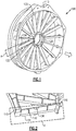
- FIG. 1 schematically illustrates an exemplary fan inlet case 100.
- the fan inlet case 100 includes an outer support ring 110 for connecting to an outer fan nacelle, and an inner support ring 120 for connecting to an inner diameter support structure of the fan.
- Multiple aerodynamic struts 130 span from the inner support ring 120 to the outer support rings 110 and provide structural support to the fan nacelle when the fan inlet case 100 structure is installed in a gas turbine engine.
- An erosion resistant coating is applied to the surface of the fan inlet case 100. The erosion resistant coating reduces the impact of erosion during operation of the gas turbine engine.
- Each of the struts 130 includes a leading edge 132 and a trailing edge 134.
- the leading edge 132 directly contacts the incoming air, while the trailing edge 134 has minimal contact. Further, the contact between ingested particulate is highest at the leading edge 132 of the strut 130, and gradually reduces as the contact approaches the trailing edge 134. As a result of this contact gradient, the leading edge 132 is exposed to substantially higher levels of erosion than the trailing edge 134.
- Figure 2 schematically illustrates a zoomed in view of a single strut 130 of the fan inlet case 100 of Figure 1 .
- the strut 130 includes an eroded section 136 at the leading edge 132 where a portion 136 of the coating is worn, chipped, or eroded.
- existing repair methods place a patch over the eroded portion 136, and apply a steady heat and pressure for a predetermined amount of time. The application of the heat and pressure causes the patch to adhere to, and integrate into the erosion resistant coating, thereby repairing the eroded portion 136.
- the difficulty in applying the patch extends to any component where a patch is needed at a relatively sharp angled surface, any surface that has a curvature with a substantially small radius of curvature, or any component where the damaged surface is sufficiently complex in shape and the repair tool is not limited specifically to fan inlet case strut components.
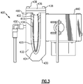
- Figure 3 schematically illustrates an exemplary repair tool 400 for applying a repair patch 404 to a strut 402.
- the repair tool 400 is positioned about the strut 402, and includes a heating element 410, a flexible bladder 420 and an inflexible shell 430.
- a controller 440 is connected to the repair shell 430, and provides electrical power and controls to the repair tool 400.
- An exemplary patch 404 for utilization with the repair tool 400 includes a two part erosion coating having a prefabricated film patch with an adhesive applied to one side according to a known patching technique.
- the adhesive side is applied to the strut 402, and pressure and heat are generated by the repair tool 400.
- a steady pressure and heat is applied for an extended duration.
- a pressure of 25-30 pounds per square inch (psi) (172 - 207 kPa) and a temperature of approximately 300 F (149 C) should be applied for a duration of two hours in one example.
- the heating element 410 is heated and controlled by the controller 440.
- a temperature sensor can be included in order to further control the temperature of the heating element 410.
- the controller 440 can provide a constant electrical current to the heating element 410, thereby ensuring that a constant temperature is generated, and no active temperature sensing is required.
- the heating element 410 is applied directly adjacent to the complex surface where the patch 404 is located.
- the controller 440 causes the flexible bladder 420 to be inflated to a predetermined pressure. While the inflation of the flexible bladder 420 remains constant, the pressure exerted by the tool 400 on the patch 404 and the strut 402 also remains constant. The flow of air, or another inflation fluid, into the flexible bladder 420 is controlled via the controller 440 and a valve 450. In some exemplary embodiments, the pressure exerted by the flexible bladder 420 is measured via a pressure sensor disposed between the flexible bladder 420 and the heating element 410, and the amount of fluid in the flexible bladder 420 is actively controlled by the controller 440 and the valve 450. In alternative embodiments, a known amount of fluid exerts a known and constant pressure, and the controller 440 fills the flexible bladder 420 with the known amount of fluid. In the alternative embodiment, active monitoring of the pressure exerted by the flexible bladder 420 is not necessary.
- the inflexible shell 430 can be constructed of any rigid material. By way of example, one embodiment utilizes an aluminum material to construct the inflexible shell 430.
- the inflexible shell 430 includes a first portion 432 having an interior cavity defining a negative space 434.
- the negative space 434 defined by the interior cavity corresponds to the three dimensional shape of the complex surface to which the patch 404 is being applied.
- a clamp portion 436 that is connected to the first portion 432 of the rigid shell 430 via one or more fasteners 438 that are configured to be tightened. Once tightened to the remainder of the shell, the clamp portion 436 maintains the shell 430 in position about the strut 402, or other component to which the patch 404 is being applied.
- the patching process can generate outgasses from the adhesive bonding process. If the outgasses remain trapped within the tool 400, adhesion of the patch 404 can be reduced, or flaws can be introduced into the bonding process.
- an outgassing vent 460 is included at the joint between the clamp portion 436 and the first portion 432 of the shell 430. As the pressure is applied directly via the flexible bladder 420, the lack of sealing resulting from the outgassing vent 460 does not impact the pressure exerted on the patch 404.
- FIG. 4 schematically illustrates an exemplary heating element 410.
- the exemplary heating element 410 is a flexible silicon heating pad.
- the element 410 includes an electrical lead 412 that connects to a controller and provides the electrical current for the element 410 to generate heat. Due to the flexible nature of the heating element 410, the element 410 can include a bend 414, or other contour, that matches the contour of the surface to which the patch 404 is being applied.
- FIG 5 schematically illustrates the flexible bladder 420 of Figure 3 isolated from the repair tool 400.
- the flexible bladder 420 is constructed of a flexible, thermally insulating rubber material, and is connected to a valve 450 via an inflation tube 452.
- the flexible nature of the bladder 420 allows for the incorporation of a bend 424, or other curvature, that matches the curvature of the patch 404.
- the insulating nature of the rubber causes heat generated by the heating element 410 to be maintained at a steady temperature without requiring constant monitoring and controlling, and also forces the heat to be directly applied to the patch 404 and the strut 402.
- Figure 6 schematically illustrates the inflexible shell 430 of Figure 3 , with a remainder of the tool 400 removed.
- the inflexible shell 430 defines an internal negative space 434 corresponding to the three dimensional surface of the component to which the patch 404 is being applied.
- the illustrated shell 430 is constructed having an internal negative space 434 conformed to a leading edge of a fan inlet case strut, and the shell 430 extends the entire length of the fan inlet case strut.
- the negative space 434 can be constructed according to the dimensions of the component being repaired.
- the negative space 434 is also offset from the surface being repaired by a set amount in order to account for the presence of the heating element 410 and the flexible bladder 420.
- the heating element 410 is applied to the strut, then the bladder 420 is applied directly to the heating element, and the shell 430 is slid around the strut 402, heating element 410 and the bladder 420.
- the shell 430 is then clamped into place via the clamping portion 436, and the application of pressure and temperature can begin.
- the patch 404 is positioned over the damaged portion of the strut 402.
- the heating element 410 is applied directly in contact with the patch 404 and the strut 402
- the flexible bladder 420 is positioned around the heating element 410
- the inflexible shell 430 is positioned about the flexible bladder 420, the heating element 410, and the strut 402. Due to the flexible nature of the heating element 410 and the flexible bladder 420, a bend in the heating element 410 and the bladder 420 is positioned adjacent a corresponding bend in both the strut 402 and the negative space 434 of the inflexible shell 430.
- heat from the heating element 410 is applied by activating the heating element 410. Simultaneously, pressure is applied by inflating the flexible bladder 420 adjacent to the heating element 410.
- the thermally insulating nature of the flexible bladder 420 maintains the heat from the heating element 410 at the patch 404.
- a controller 440 controls both the heat produced by the heating element 410 and the pressure exerted on the patch 404 by the bladder 420.
- the bladder 420 and heating element 410 are maintained in position against the patch 404 within the negative space 434 defined by the inflexible shell 430, thereby ensuring that a constant temperature and pressure can be provided for the necessary duration.
- pressure is applied in the range of 25 to 30 psi (172 to 207 kPa) and heat is applied at a temperature of approximately 300 F (149 C) for a duration of approximately two hours.
- psi 172 to 207 kPa
- heat is applied at a temperature of approximately 300 F (149 C) for a duration of approximately two hours.
Landscapes
- Engineering & Computer Science (AREA)
- Mechanical Engineering (AREA)
Abstract
Description
- The present disclosure relates generally to a tool for applying a repair patch for aircraft component coatings, and more specifically to a tool for applying uniform heat and pressure to a coating patch.
- Gas powered turbines ingest air at high velocities during operation. The ingestion of air carries with it the ingestion of particulate that is entrained in the air stream. Contact between the particulate and the structural components of the gas powered turbine can result in erosion damage to the contacted surfaces of the component.
- In order to minimize erosion damage, structures, and particularly composite structures, include an erosion resistant coating that is applied to the original manufacture. The erosion resistant coating minimizes erosion damage to the underlying component without substantially changing the dimensions of the underlying component. During operation of the engine, the erosion resistant coating is worn down either due to long term erosion, ingested object impacts, or a combination of the two. Further, this wear on the erosion resistant coating is not uniform, and can be substantially higher at certain positions of the component.
- As a result of the increased wear at certain positions, it is more efficient to patch the erosion resistant coating at the high wear locations than it is to reapply the entire coating. However, the same features that subject the high wear locations to increased wear make the application of the repair patch more difficult.
- In one exemplary embodiment a repair tool for applying a coating patch includes a heating element, a flexible bladder disposed adjacent the heating element, an inflexible shell disposed about the flexible bladder, the inflexible shell defining a negative space corresponding to a plurality of sides of an aircraft component, and a controller communicatively coupled to the heating element and the bladder, the controller being configured to control a temperature of the heating element and a pressure of the flexible bladder.
- In another example of the above described repair tool for applying a coating patch the inflexible shell is configured to at least partially surround the aircraft component.
- In another example of any of the above described repair tools for applying a coating patch the flexible bladder is filled with a fluid, and wherein a pressure exerted on a patch is controlled by an amount of fluid in the flexible bladder.
- In another example of any of the above described repair tools for applying a coating patch the heating element is a heating blanket.
- In another example of any of the above described repair tools for applying a coating patch the heating blanket is a silicon heating blanket.
- Another example of any of the above described repair tools for applying a coating patch further includes at least one temperature sensor configured to detect a temperature of the heating element and at least one pressure sensor configured to detect a pressure exerted by the flexible bladder.
- In another example of any of the above described repair tools for applying a coating patch each of the at least one temperature sensor and the at least one pressure sensor is communicatively coupled to the controller.
- In another example of any of the above described repair tools for applying a coating patch the flexible bladder is thermally insulating.
- In another example of any of the above described repair tools for applying a coating patch the flexible bladder is an air filled bladder.
- In another example of any of the above described repair tools for applying a coating patch the negative space corresponds to a fan inlet case strut for a gas turbine engine.
- In another example of any of the above described repair tools for applying a coating patch the heating element includes a complex curvature at a patching position.
- In another example of any of the above described repair tools for applying a coating patch the complex curvature is an approximately 180 degree bend.
- In another example of any of the above described repair tools for applying a coating patch the bladder includes a complex curvature at the patching position.
- In another example of any of the above described repair tools for applying a coating patch the shell further defines an outgas vent path configured to allow adhesive outgassing to vent.
- An exemplary method for applying a coating path includes positioning a patch over a damaged section of a component, applying heat to the patch by activating a heating element in contact with the patch, applying pressure to the patch by inflating a flexible bladder adjacent to the heating element, and maintaining a position of the flexible bladder and the heating element in an inflexible shell, the inflexible shell defining a negative space corresponding to at least the damaged section of the component.
- In another example of the above described exemplary method for applying a coating path applying heat to the patch by activating the heating element in contact with the patch comprises positioning the heating element such that a bend in the heating element is in contact with the patch.
- In another example of any of the above described exemplary methods for applying a coating path applying pressure to the patch by inflating the flexible bladder further comprises insulating the patch such that heat from the heating element is retained at the patch.
- In another example of any of the above described exemplary methods for applying a coating path the step of applying pressure to the patch by inflating a flexible bladder adjacent to the heating element applies a pressure in the range of 25 to 30 psi (172 to 207 kPa) and applying heat to the patch comprises maintaining a temperature at the patch of approximately 300 F (149 C).
- In another example of any of the above described exemplary methods for applying a coating path the steps of applying pressure to the patch and applying heat to the patch are performed for approximately 2 hours.
- These and other features of the present invention can be best understood from the following specification and drawings, the following of which is a brief description.
-
-
Figure 1 schematically illustrates an exemplary fan inlet case for a gas turbine engine. -
Figure 2 schematically illustrates a single strut of the exemplary fan inlet case ofFigure 1 . -
Figure 3 schematically illustrates an assembled repair tool positioned around a fan inlet case strut. -
Figure 4 schematically illustrates a heating element component of a repair tool. -
Figure 5 schematically illustrates a flexible bladder component of a repair tool. -
Figure 6 schematically illustrates an inflexible shell component of a repair tool. - Gas turbine engines, such as those utilized on commercial aircraft use a compressor to compress air, a combustor to mix the compressed air with a fuel and ignite the mixture, and a turbine section across which the resultant combustion gasses are expanded. The expansion drives the turbine section to rotate. The turbine section is connected to the compressor via one or more shaft, and the rotation of the turbine drives rotation of the compressor. Also connected to the shaft either directly, in a direct drive configuration, or through a gear system, in a geared fan configuration, is a fan. The rotation of the shaft drives rotation of the fan. The rotation of the fan, in turn, ingests air to a fan bypass duct.
- Due to the ingestion of air at both the compressor and the fan, particulate that is entrained in the ambient air is frequently ingested as well. Contact between the particulate and the engine components erodes an erosion resistant coating that is applied to the components exposed to the flowpath. One such exemplary component is a fan inlet case.
-
Figure 1 schematically illustrates an exemplaryfan inlet case 100. Thefan inlet case 100 includes anouter support ring 110 for connecting to an outer fan nacelle, and aninner support ring 120 for connecting to an inner diameter support structure of the fan. Multipleaerodynamic struts 130 span from theinner support ring 120 to theouter support rings 110 and provide structural support to the fan nacelle when thefan inlet case 100 structure is installed in a gas turbine engine. An erosion resistant coating is applied to the surface of thefan inlet case 100. The erosion resistant coating reduces the impact of erosion during operation of the gas turbine engine. - Each of the
struts 130 includes a leadingedge 132 and atrailing edge 134. The leadingedge 132 directly contacts the incoming air, while thetrailing edge 134 has minimal contact. Further, the contact between ingested particulate is highest at the leadingedge 132 of thestrut 130, and gradually reduces as the contact approaches thetrailing edge 134. As a result of this contact gradient, the leadingedge 132 is exposed to substantially higher levels of erosion than thetrailing edge 134. - With continued reference to
Figure 1, Figure 2 schematically illustrates a zoomed in view of asingle strut 130 of thefan inlet case 100 ofFigure 1 . Thestrut 130 includes aneroded section 136 at the leadingedge 132 where aportion 136 of the coating is worn, chipped, or eroded. In order to repair eroded sections of erosion resistant coatings, existing repair methods place a patch over the erodedportion 136, and apply a steady heat and pressure for a predetermined amount of time. The application of the heat and pressure causes the patch to adhere to, and integrate into the erosion resistant coating, thereby repairing the erodedportion 136. - Due to the extreme curvature of the leading
edge 132, it is difficult, or impossible, to use existing methods and tools to apply the patch to the leadingedge 132. While illustrated and shown herein on the fan inlet case strut, one of skill in the art having the benefit of this disclosure will appreciate that the difficulty in applying the patch extends to any component where a patch is needed at a relatively sharp angled surface, any surface that has a curvature with a substantially small radius of curvature, or any component where the damaged surface is sufficiently complex in shape and the repair tool is not limited specifically to fan inlet case strut components. - In order to apply a patch to complex surfaces via existing systems, the application of pressure and temperature is achieved by placing the entire component in an autoclave. A drawback to this application procedure is that autoclaves are expensive and large, and thus are often far removed from the site where repairs are needed. The component being repaired is shipped to an offsite location, increasing the repair time by a substantial amount.
- With continued reference to
Figures 1 and 2 ,Figure 3 schematically illustrates anexemplary repair tool 400 for applying arepair patch 404 to astrut 402. Therepair tool 400 is positioned about thestrut 402, and includes aheating element 410, aflexible bladder 420 and aninflexible shell 430. Acontroller 440 is connected to therepair shell 430, and provides electrical power and controls to therepair tool 400. - An
exemplary patch 404 for utilization with therepair tool 400 includes a two part erosion coating having a prefabricated film patch with an adhesive applied to one side according to a known patching technique. The adhesive side is applied to thestrut 402, and pressure and heat are generated by therepair tool 400. In order to properly adhere thepatch 404 to thestrut 402, a steady pressure and heat is applied for an extended duration. By way of example, in one embodiment a pressure of 25-30 pounds per square inch (psi) (172 - 207 kPa) and a temperature of approximately 300 F (149 C) should be applied for a duration of two hours in one example. - In order to achieve the desired temperature, the
heating element 410 is heated and controlled by thecontroller 440. In some examples, a temperature sensor can be included in order to further control the temperature of theheating element 410. In alternative examples, thecontroller 440 can provide a constant electrical current to theheating element 410, thereby ensuring that a constant temperature is generated, and no active temperature sensing is required. In theexemplary tool 400, theheating element 410 is applied directly adjacent to the complex surface where thepatch 404 is located. - In order to ensure that sufficient pressure is applied and maintained for the entire duration, the
controller 440 causes theflexible bladder 420 to be inflated to a predetermined pressure. While the inflation of theflexible bladder 420 remains constant, the pressure exerted by thetool 400 on thepatch 404 and thestrut 402 also remains constant. The flow of air, or another inflation fluid, into theflexible bladder 420 is controlled via thecontroller 440 and avalve 450. In some exemplary embodiments, the pressure exerted by theflexible bladder 420 is measured via a pressure sensor disposed between theflexible bladder 420 and theheating element 410, and the amount of fluid in theflexible bladder 420 is actively controlled by thecontroller 440 and thevalve 450. In alternative embodiments, a known amount of fluid exerts a known and constant pressure, and thecontroller 440 fills theflexible bladder 420 with the known amount of fluid. In the alternative embodiment, active monitoring of the pressure exerted by theflexible bladder 420 is not necessary. - At least partially surrounding the
flexible bladder 420, theheating element 410, and thestrut 402 is aninflexible shell 430. Theinflexible shell 430 can be constructed of any rigid material. By way of example, one embodiment utilizes an aluminum material to construct theinflexible shell 430. Theinflexible shell 430 includes afirst portion 432 having an interior cavity defining anegative space 434. Thenegative space 434 defined by the interior cavity corresponds to the three dimensional shape of the complex surface to which thepatch 404 is being applied. - Enclosing the
negative space 434 is aclamp portion 436 that is connected to thefirst portion 432 of therigid shell 430 via one ormore fasteners 438 that are configured to be tightened. Once tightened to the remainder of the shell, theclamp portion 436 maintains theshell 430 in position about thestrut 402, or other component to which thepatch 404 is being applied. - In some examples, the patching process can generate outgasses from the adhesive bonding process. If the outgasses remain trapped within the
tool 400, adhesion of thepatch 404 can be reduced, or flaws can be introduced into the bonding process. In order to accommodate the outgassing, anoutgassing vent 460 is included at the joint between theclamp portion 436 and thefirst portion 432 of theshell 430. As the pressure is applied directly via theflexible bladder 420, the lack of sealing resulting from theoutgassing vent 460 does not impact the pressure exerted on thepatch 404. - With continued reference to
Figures 1-3 , and with like numerals indicating like elements,Figure 4 schematically illustrates anexemplary heating element 410. Theexemplary heating element 410 is a flexible silicon heating pad. Theelement 410 includes anelectrical lead 412 that connects to a controller and provides the electrical current for theelement 410 to generate heat. Due to the flexible nature of theheating element 410, theelement 410 can include abend 414, or other contour, that matches the contour of the surface to which thepatch 404 is being applied. - With continued reference to
Figures 1-4 , and with like numerals indicating like elements,Figure 5 schematically illustrates theflexible bladder 420 ofFigure 3 isolated from therepair tool 400. Theflexible bladder 420 is constructed of a flexible, thermally insulating rubber material, and is connected to avalve 450 via aninflation tube 452. As with theheating element 410, the flexible nature of thebladder 420 allows for the incorporation of abend 424, or other curvature, that matches the curvature of thepatch 404. The insulating nature of the rubber causes heat generated by theheating element 410 to be maintained at a steady temperature without requiring constant monitoring and controlling, and also forces the heat to be directly applied to thepatch 404 and thestrut 402. - With continued reference to
Figures 1-5 ,Figure 6 schematically illustrates theinflexible shell 430 ofFigure 3 , with a remainder of thetool 400 removed. As described previously, theinflexible shell 430 defines an internalnegative space 434 corresponding to the three dimensional surface of the component to which thepatch 404 is being applied. The illustratedshell 430 is constructed having an internalnegative space 434 conformed to a leading edge of a fan inlet case strut, and theshell 430 extends the entire length of the fan inlet case strut. In alternative examples, where alternative components are being repaired, thenegative space 434 can be constructed according to the dimensions of the component being repaired. - The
negative space 434 is also offset from the surface being repaired by a set amount in order to account for the presence of theheating element 410 and theflexible bladder 420. When utilized, theheating element 410 is applied to the strut, then thebladder 420 is applied directly to the heating element, and theshell 430 is slid around thestrut 402,heating element 410 and thebladder 420. Theshell 430 is then clamped into place via the clampingportion 436, and the application of pressure and temperature can begin. - With further reference to
Figure 3 , an exemplary method for applying thecoating patch 404 is described herein. Initially, thepatch 404 is positioned over the damaged portion of thestrut 402. Once positioned, theheating element 410 is applied directly in contact with thepatch 404 and thestrut 402, theflexible bladder 420 is positioned around theheating element 410, and theinflexible shell 430 is positioned about theflexible bladder 420, theheating element 410, and thestrut 402. Due to the flexible nature of theheating element 410 and theflexible bladder 420, a bend in theheating element 410 and thebladder 420 is positioned adjacent a corresponding bend in both thestrut 402 and thenegative space 434 of theinflexible shell 430. - Once in position, heat from the
heating element 410 is applied by activating theheating element 410. Simultaneously, pressure is applied by inflating theflexible bladder 420 adjacent to theheating element 410. The thermally insulating nature of theflexible bladder 420 maintains the heat from theheating element 410 at thepatch 404. Acontroller 440 controls both the heat produced by theheating element 410 and the pressure exerted on thepatch 404 by thebladder 420. - The
bladder 420 andheating element 410 are maintained in position against thepatch 404 within thenegative space 434 defined by theinflexible shell 430, thereby ensuring that a constant temperature and pressure can be provided for the necessary duration. In one exemplary embodiment, pressure is applied in the range of 25 to 30 psi (172 to 207 kPa) and heat is applied at a temperature of approximately 300 F (149 C) for a duration of approximately two hours. One of skill in the art having the benefit of this disclosure will understand that alternative temperature and pressure ranges could be realized depending on the specific needs of a given patch and adhesive. - It is further understood that any of the above described concepts can be used alone or in combination with any or all of the other above described concepts. Although an embodiment of this invention has been disclosed, a worker of ordinary skill in this art would recognize that certain modifications would come within the scope of this invention. For that reason, the following claims should be studied to determine the true scope and content of this invention.
Claims (15)
- A repair tool (400) for applying a coating patch (404) comprising:a heating element (410);a flexible bladder (420) disposed adjacent the heating element (410);an inflexible shell (430) disposed about the flexible bladder (420), the inflexible shell (430) defining a negative space (434) corresponding to a plurality of sides of an aircraft component; anda controller (440) communicatively coupled to the heating element (410) and the bladder (420), the controller (440) being configured to control a temperature of the heating element (410) and a pressure of the flexible bladder (420).
- The repair tool (400) of claim 1, wherein the inflexible shell (440) is configured to at least partially surround the aircraft component.
- The repair tool (400) of claim 1 or 2, wherein the flexible bladder (420) is filled with a fluid, and wherein a pressure exerted on a patch (404) is controlled by an amount of fluid in the flexible bladder (420).
- The repair tool (400) of any preceding claim, wherein the heating element (410) is a heating blanket, wherein, optionally, the heating blanket is a silicon heating blanket.
- The repair tool (400) of any preceding claim, further comprising at least one temperature sensor configured to detect a temperature of the heating element (410) and at least one pressure sensor configured to detect a pressure exerted by the flexible bladder (420), wherein, optionally, each of the at least one temperature sensor and the at least one pressure sensor is communicatively coupled to the controller (440).
- The repair tool (400) of any preceding claim, wherein the flexible bladder (420) is thermally insulating.
- The repair tool (400) of any preceding claim, wherein the flexible bladder (420) is an air filled bladder.
- The repair tool (400) of any preceding claim, wherein the negative space (434) corresponds to a fan inlet case strut (402) for a gas turbine engine.
- The repair tool (400) of any preceding claim, wherein the heating element (410) includes a complex curvature at a patching position, wherein, optionally, the complex curvature is an approximately 180 degree bend.
- The repair tool (400) of claim 9, wherein the bladder (420) includes a complex curvature at the patching position.
- The repair tool (400) of any preceding claim, wherein the shell (430) further defines an outgas vent (460) path configured to allow adhesive outgassing to vent.
- A method for applying a coating patch comprising:positioning a patch (404) over a damaged section of a component;applying heat to the patch by activating a heating element (410) in contact with the patch (404);applying pressure to the patch (404) by inflating a flexible bladder (420) adjacent to the heating element (410); andmaintaining a position of the flexible bladder (420) and the heating element (410) in an inflexible shell (430), the inflexible shell (430) defining a negative space (434) corresponding to at least the damaged section of the component.
- The method of claim 12, wherein applying heat to the patch by activating the heating element (410) in contact with the patch (404) further comprises positioning the heating element (410) such that a bend in the heating element (410) is in contact with the patch (404).
- The method of claim 12 or 13, wherein applying pressure to the patch (404) by inflating the flexible bladder (420) further comprises insulating the patch (404) such that heat from the heating element (410) is retained at the patch (404).
- The method of any of claims 12 to 14, wherein the step of applying pressure to the patch (404) by inflating a flexible bladder (420) adjacent to the heating element (410) applies a pressure in the range of 25 to 30 psi (172 to 207 kPa) and applying heat to the patch (404) comprises maintaining a temperature at the patch of approximately 300 F (149 C), wherein, optionally, the steps of applying pressure to the patch (404) and applying heat to the patch (404) are performed for approximately 2 hours.
Applications Claiming Priority (1)
| Application Number | Priority Date | Filing Date | Title |
|---|---|---|---|
| US15/610,777 US10875266B2 (en) | 2017-06-01 | 2017-06-01 | Aircraft repair patch applicator tool |
Publications (2)
| Publication Number | Publication Date |
|---|---|
| EP3409456A1 true EP3409456A1 (en) | 2018-12-05 |
| EP3409456B1 EP3409456B1 (en) | 2023-07-05 |
Family
ID=62620618
Family Applications (1)
| Application Number | Title | Priority Date | Filing Date |
|---|---|---|---|
| EP18173919.4A Active EP3409456B1 (en) | 2017-06-01 | 2018-05-23 | Aircraft repair patch application tool |
Country Status (2)
| Country | Link |
|---|---|
| US (1) | US10875266B2 (en) |
| EP (1) | EP3409456B1 (en) |
Cited By (1)
| Publication number | Priority date | Publication date | Assignee | Title |
|---|---|---|---|---|
| EP4721962A1 (en) * | 2024-10-03 | 2026-04-08 | RTX Corporation | Method and apparatus for controlled thickness patch adjacent filleted surfaces |
Families Citing this family (1)
| Publication number | Priority date | Publication date | Assignee | Title |
|---|---|---|---|---|
| US20250026092A1 (en) | 2023-07-21 | 2025-01-23 | Rtx Corporation | Turbine Engine Erosion Coating Repair |
Citations (3)
| Publication number | Priority date | Publication date | Assignee | Title |
|---|---|---|---|---|
| US4708608A (en) * | 1986-06-17 | 1987-11-24 | Dirocco Jobbie | Heat pad |
| FR2705914A1 (en) * | 1993-06-02 | 1994-12-09 | Aerospatiale | Device for applying pressure, optionally with heat, onto a surface of any shape, in particular for repairing damaged structures |
| JPH08192484A (en) * | 1995-01-13 | 1996-07-30 | Showa Aircraft Ind Co Ltd | Adhesive device |
Family Cites Families (6)
| Publication number | Priority date | Publication date | Assignee | Title |
|---|---|---|---|---|
| US5296173A (en) * | 1991-12-04 | 1994-03-22 | Vulcan Vulcap Industries, Inc. | Tire section repair unit and method |
| US5935360A (en) * | 1997-09-24 | 1999-08-10 | General Electric Company | Method for repairing a strip bonded to an article surface |
| US5975183A (en) | 1998-03-23 | 1999-11-02 | Northrop Grumman Corporation | Repair pressure applicator for in the field damaged aircraft |
| US20100024185A1 (en) * | 2007-02-21 | 2010-02-04 | United Technologies Corporation | Complete wire mesh repair with heat blanket |
| DE102007026099A1 (en) | 2007-06-05 | 2008-12-11 | Airbus Deutschland Gmbh | Apparatus and method for processing a fiber composite structure |
| WO2014143224A1 (en) | 2013-03-15 | 2014-09-18 | United Technologies Corporation | Turbine engine repair methods |
-
2017
- 2017-06-01 US US15/610,777 patent/US10875266B2/en active Active
-
2018
- 2018-05-23 EP EP18173919.4A patent/EP3409456B1/en active Active
Patent Citations (3)
| Publication number | Priority date | Publication date | Assignee | Title |
|---|---|---|---|---|
| US4708608A (en) * | 1986-06-17 | 1987-11-24 | Dirocco Jobbie | Heat pad |
| FR2705914A1 (en) * | 1993-06-02 | 1994-12-09 | Aerospatiale | Device for applying pressure, optionally with heat, onto a surface of any shape, in particular for repairing damaged structures |
| JPH08192484A (en) * | 1995-01-13 | 1996-07-30 | Showa Aircraft Ind Co Ltd | Adhesive device |
Cited By (1)
| Publication number | Priority date | Publication date | Assignee | Title |
|---|---|---|---|---|
| EP4721962A1 (en) * | 2024-10-03 | 2026-04-08 | RTX Corporation | Method and apparatus for controlled thickness patch adjacent filleted surfaces |
Also Published As
| Publication number | Publication date |
|---|---|
| US20180345608A1 (en) | 2018-12-06 |
| US10875266B2 (en) | 2020-12-29 |
| EP3409456B1 (en) | 2023-07-05 |
Similar Documents
| Publication | Publication Date | Title |
|---|---|---|
| US7278208B2 (en) | Method of replacing an abradable portion on the casing on a turbojet fan | |
| US8894358B2 (en) | Clearance control arrangement | |
| JP6694897B2 (en) | Method and system for joining | |
| EP2103779A1 (en) | Methods and apparatuses for correcting twist angle in a gas turbine engine blade | |
| EP3409456B1 (en) | Aircraft repair patch application tool | |
| JPH11270350A (en) | Method for repairing turbo machine structure in jobsite | |
| EP2604804A2 (en) | Fan blade tip clearance control | |
| US10094220B2 (en) | Turbine engine repair methods | |
| US20080236739A1 (en) | Method of applying a constrained layer damping material | |
| CN109723509B (en) | Method for applying ribs to aerodynamic surfaces and resulting device | |
| US12258873B2 (en) | Systems and method for use in servicing a machine | |
| EP3208418B1 (en) | System for repairing a bend in a turbine blade | |
| EP3203017A1 (en) | Method of remotely stopping a crack in a component of a gas turbine engine | |
| EP2022600A1 (en) | Replacement of a lubricant layer bonded to a part of a gas turbine engine | |
| US20220252010A1 (en) | Post-shutdown engine heat removal system | |
| US11639052B2 (en) | Layer debonding | |
| EP4190557A1 (en) | Machining of ceramic matrix composite during preforming and partial densification | |
| EP1529925A2 (en) | Method and apparatus for arresting a crack within a ceramic matrix composite body | |
| US11819966B2 (en) | Repair methods and systems for honeycomb structures in gas turbine engines | |
| US20230278150A1 (en) | Machining of ceramic matrix composite during preforming and partial densification | |
| NL2002340C2 (en) | Method for repairing a cooled turbine nozzle segment. | |
| EP3666405A1 (en) | Apparatus and methods for cleaning internal cavities of blades | |
| EP2960431A1 (en) | Systems and methods for repairing a surface of damaged metal components |
Legal Events
| Date | Code | Title | Description |
|---|---|---|---|
| PUAI | Public reference made under article 153(3) epc to a published international application that has entered the european phase |
Free format text: ORIGINAL CODE: 0009012 |
|
| STAA | Information on the status of an ep patent application or granted ep patent |
Free format text: STATUS: THE APPLICATION HAS BEEN PUBLISHED |
|
| AK | Designated contracting states |
Kind code of ref document: A1 Designated state(s): AL AT BE BG CH CY CZ DE DK EE ES FI FR GB GR HR HU IE IS IT LI LT LU LV MC MK MT NL NO PL PT RO RS SE SI SK SM TR |
|
| AX | Request for extension of the european patent |
Extension state: BA ME |
|
| STAA | Information on the status of an ep patent application or granted ep patent |
Free format text: STATUS: REQUEST FOR EXAMINATION WAS MADE |
|
| 17P | Request for examination filed |
Effective date: 20190605 |
|
| RBV | Designated contracting states (corrected) |
Designated state(s): AL AT BE BG CH CY CZ DE DK EE ES FI FR GB GR HR HU IE IS IT LI LT LU LV MC MK MT NL NO PL PT RO RS SE SI SK SM TR |
|
| RAP1 | Party data changed (applicant data changed or rights of an application transferred) |
Owner name: RAYTHEON TECHNOLOGIES CORPORATION |
|
| STAA | Information on the status of an ep patent application or granted ep patent |
Free format text: STATUS: EXAMINATION IS IN PROGRESS |
|
| 17Q | First examination report despatched |
Effective date: 20210929 |
|
| GRAP | Despatch of communication of intention to grant a patent |
Free format text: ORIGINAL CODE: EPIDOSNIGR1 |
|
| STAA | Information on the status of an ep patent application or granted ep patent |
Free format text: STATUS: GRANT OF PATENT IS INTENDED |
|
| INTG | Intention to grant announced |
Effective date: 20230215 |
|
| GRAS | Grant fee paid |
Free format text: ORIGINAL CODE: EPIDOSNIGR3 |
|
| GRAA | (expected) grant |
Free format text: ORIGINAL CODE: 0009210 |
|
| STAA | Information on the status of an ep patent application or granted ep patent |
Free format text: STATUS: THE PATENT HAS BEEN GRANTED |
|
| AK | Designated contracting states |
Kind code of ref document: B1 Designated state(s): AL AT BE BG CH CY CZ DE DK EE ES FI FR GB GR HR HU IE IS IT LI LT LU LV MC MK MT NL NO PL PT RO RS SE SI SK SM TR |
|
| REG | Reference to a national code |
Ref country code: CH Ref legal event code: EP |
|
| REG | Reference to a national code |
Ref country code: AT Ref legal event code: REF Ref document number: 1584460 Country of ref document: AT Kind code of ref document: T Effective date: 20230715 |
|
| REG | Reference to a national code |
Ref country code: DE Ref legal event code: R096 Ref document number: 602018052714 Country of ref document: DE |
|
| REG | Reference to a national code |
Ref country code: IE Ref legal event code: FG4D |
|
| REG | Reference to a national code |
Ref country code: LT Ref legal event code: MG9D |
|
| RAP4 | Party data changed (patent owner data changed or rights of a patent transferred) |
Owner name: RTX CORPORATION |
|
| REG | Reference to a national code |
Ref country code: NL Ref legal event code: MP Effective date: 20230705 |
|
| REG | Reference to a national code |
Ref country code: AT Ref legal event code: MK05 Ref document number: 1584460 Country of ref document: AT Kind code of ref document: T Effective date: 20230705 |
|
| PG25 | Lapsed in a contracting state [announced via postgrant information from national office to epo] |
Ref country code: NL Free format text: LAPSE BECAUSE OF FAILURE TO SUBMIT A TRANSLATION OF THE DESCRIPTION OR TO PAY THE FEE WITHIN THE PRESCRIBED TIME-LIMIT Effective date: 20230705 |
|
| PG25 | Lapsed in a contracting state [announced via postgrant information from national office to epo] |
Ref country code: GR Free format text: LAPSE BECAUSE OF FAILURE TO SUBMIT A TRANSLATION OF THE DESCRIPTION OR TO PAY THE FEE WITHIN THE PRESCRIBED TIME-LIMIT Effective date: 20231006 |
|
| PG25 | Lapsed in a contracting state [announced via postgrant information from national office to epo] |
Ref country code: ES Free format text: LAPSE BECAUSE OF FAILURE TO SUBMIT A TRANSLATION OF THE DESCRIPTION OR TO PAY THE FEE WITHIN THE PRESCRIBED TIME-LIMIT Effective date: 20230705 |
|
| PG25 | Lapsed in a contracting state [announced via postgrant information from national office to epo] |
Ref country code: IS Free format text: LAPSE BECAUSE OF FAILURE TO SUBMIT A TRANSLATION OF THE DESCRIPTION OR TO PAY THE FEE WITHIN THE PRESCRIBED TIME-LIMIT Effective date: 20231105 |
|
| PG25 | Lapsed in a contracting state [announced via postgrant information from national office to epo] |
Ref country code: SE Free format text: LAPSE BECAUSE OF FAILURE TO SUBMIT A TRANSLATION OF THE DESCRIPTION OR TO PAY THE FEE WITHIN THE PRESCRIBED TIME-LIMIT Effective date: 20230705 Ref country code: RS Free format text: LAPSE BECAUSE OF FAILURE TO SUBMIT A TRANSLATION OF THE DESCRIPTION OR TO PAY THE FEE WITHIN THE PRESCRIBED TIME-LIMIT Effective date: 20230705 Ref country code: PT Free format text: LAPSE BECAUSE OF FAILURE TO SUBMIT A TRANSLATION OF THE DESCRIPTION OR TO PAY THE FEE WITHIN THE PRESCRIBED TIME-LIMIT Effective date: 20231106 Ref country code: NO Free format text: LAPSE BECAUSE OF FAILURE TO SUBMIT A TRANSLATION OF THE DESCRIPTION OR TO PAY THE FEE WITHIN THE PRESCRIBED TIME-LIMIT Effective date: 20231005 Ref country code: LV Free format text: LAPSE BECAUSE OF FAILURE TO SUBMIT A TRANSLATION OF THE DESCRIPTION OR TO PAY THE FEE WITHIN THE PRESCRIBED TIME-LIMIT Effective date: 20230705 Ref country code: LT Free format text: LAPSE BECAUSE OF FAILURE TO SUBMIT A TRANSLATION OF THE DESCRIPTION OR TO PAY THE FEE WITHIN THE PRESCRIBED TIME-LIMIT Effective date: 20230705 Ref country code: IS Free format text: LAPSE BECAUSE OF FAILURE TO SUBMIT A TRANSLATION OF THE DESCRIPTION OR TO PAY THE FEE WITHIN THE PRESCRIBED TIME-LIMIT Effective date: 20231105 Ref country code: HR Free format text: LAPSE BECAUSE OF FAILURE TO SUBMIT A TRANSLATION OF THE DESCRIPTION OR TO PAY THE FEE WITHIN THE PRESCRIBED TIME-LIMIT Effective date: 20230705 Ref country code: GR Free format text: LAPSE BECAUSE OF FAILURE TO SUBMIT A TRANSLATION OF THE DESCRIPTION OR TO PAY THE FEE WITHIN THE PRESCRIBED TIME-LIMIT Effective date: 20231006 Ref country code: FI Free format text: LAPSE BECAUSE OF FAILURE TO SUBMIT A TRANSLATION OF THE DESCRIPTION OR TO PAY THE FEE WITHIN THE PRESCRIBED TIME-LIMIT Effective date: 20230705 Ref country code: ES Free format text: LAPSE BECAUSE OF FAILURE TO SUBMIT A TRANSLATION OF THE DESCRIPTION OR TO PAY THE FEE WITHIN THE PRESCRIBED TIME-LIMIT Effective date: 20230705 Ref country code: AT Free format text: LAPSE BECAUSE OF FAILURE TO SUBMIT A TRANSLATION OF THE DESCRIPTION OR TO PAY THE FEE WITHIN THE PRESCRIBED TIME-LIMIT Effective date: 20230705 |
|
| PG25 | Lapsed in a contracting state [announced via postgrant information from national office to epo] |
Ref country code: PL Free format text: LAPSE BECAUSE OF FAILURE TO SUBMIT A TRANSLATION OF THE DESCRIPTION OR TO PAY THE FEE WITHIN THE PRESCRIBED TIME-LIMIT Effective date: 20230705 |
|
| REG | Reference to a national code |
Ref country code: DE Ref legal event code: R097 Ref document number: 602018052714 Country of ref document: DE |
|
| PG25 | Lapsed in a contracting state [announced via postgrant information from national office to epo] |
Ref country code: SM Free format text: LAPSE BECAUSE OF FAILURE TO SUBMIT A TRANSLATION OF THE DESCRIPTION OR TO PAY THE FEE WITHIN THE PRESCRIBED TIME-LIMIT Effective date: 20230705 Ref country code: RO Free format text: LAPSE BECAUSE OF FAILURE TO SUBMIT A TRANSLATION OF THE DESCRIPTION OR TO PAY THE FEE WITHIN THE PRESCRIBED TIME-LIMIT Effective date: 20230705 Ref country code: EE Free format text: LAPSE BECAUSE OF FAILURE TO SUBMIT A TRANSLATION OF THE DESCRIPTION OR TO PAY THE FEE WITHIN THE PRESCRIBED TIME-LIMIT Effective date: 20230705 Ref country code: DK Free format text: LAPSE BECAUSE OF FAILURE TO SUBMIT A TRANSLATION OF THE DESCRIPTION OR TO PAY THE FEE WITHIN THE PRESCRIBED TIME-LIMIT Effective date: 20230705 Ref country code: CZ Free format text: LAPSE BECAUSE OF FAILURE TO SUBMIT A TRANSLATION OF THE DESCRIPTION OR TO PAY THE FEE WITHIN THE PRESCRIBED TIME-LIMIT Effective date: 20230705 Ref country code: SK Free format text: LAPSE BECAUSE OF FAILURE TO SUBMIT A TRANSLATION OF THE DESCRIPTION OR TO PAY THE FEE WITHIN THE PRESCRIBED TIME-LIMIT Effective date: 20230705 |
|
| PLBE | No opposition filed within time limit |
Free format text: ORIGINAL CODE: 0009261 |
|
| STAA | Information on the status of an ep patent application or granted ep patent |
Free format text: STATUS: NO OPPOSITION FILED WITHIN TIME LIMIT |
|
| PG25 | Lapsed in a contracting state [announced via postgrant information from national office to epo] |
Ref country code: IT Free format text: LAPSE BECAUSE OF FAILURE TO SUBMIT A TRANSLATION OF THE DESCRIPTION OR TO PAY THE FEE WITHIN THE PRESCRIBED TIME-LIMIT Effective date: 20230705 |
|
| 26N | No opposition filed |
Effective date: 20240408 |
|
| PG25 | Lapsed in a contracting state [announced via postgrant information from national office to epo] |
Ref country code: SI Free format text: LAPSE BECAUSE OF FAILURE TO SUBMIT A TRANSLATION OF THE DESCRIPTION OR TO PAY THE FEE WITHIN THE PRESCRIBED TIME-LIMIT Effective date: 20230705 |
|
| PG25 | Lapsed in a contracting state [announced via postgrant information from national office to epo] |
Ref country code: BG Free format text: LAPSE BECAUSE OF FAILURE TO SUBMIT A TRANSLATION OF THE DESCRIPTION OR TO PAY THE FEE WITHIN THE PRESCRIBED TIME-LIMIT Effective date: 20230705 |
|
| PG25 | Lapsed in a contracting state [announced via postgrant information from national office to epo] |
Ref country code: BG Free format text: LAPSE BECAUSE OF FAILURE TO SUBMIT A TRANSLATION OF THE DESCRIPTION OR TO PAY THE FEE WITHIN THE PRESCRIBED TIME-LIMIT Effective date: 20230705 |
|
| REG | Reference to a national code |
Ref country code: CH Ref legal event code: PL |
|
| PG25 | Lapsed in a contracting state [announced via postgrant information from national office to epo] |
Ref country code: MC Free format text: LAPSE BECAUSE OF FAILURE TO SUBMIT A TRANSLATION OF THE DESCRIPTION OR TO PAY THE FEE WITHIN THE PRESCRIBED TIME-LIMIT Effective date: 20230705 |
|
| PG25 | Lapsed in a contracting state [announced via postgrant information from national office to epo] |
Ref country code: LU Free format text: LAPSE BECAUSE OF NON-PAYMENT OF DUE FEES Effective date: 20240523 |
|
| PG25 | Lapsed in a contracting state [announced via postgrant information from national office to epo] |
Ref country code: MC Free format text: LAPSE BECAUSE OF FAILURE TO SUBMIT A TRANSLATION OF THE DESCRIPTION OR TO PAY THE FEE WITHIN THE PRESCRIBED TIME-LIMIT Effective date: 20230705 Ref country code: LU Free format text: LAPSE BECAUSE OF NON-PAYMENT OF DUE FEES Effective date: 20240523 Ref country code: CH Free format text: LAPSE BECAUSE OF NON-PAYMENT OF DUE FEES Effective date: 20240531 |
|
| REG | Reference to a national code |
Ref country code: BE Ref legal event code: MM Effective date: 20240531 |
|
| PG25 | Lapsed in a contracting state [announced via postgrant information from national office to epo] |
Ref country code: IE Free format text: LAPSE BECAUSE OF NON-PAYMENT OF DUE FEES Effective date: 20240523 |
|
| PG25 | Lapsed in a contracting state [announced via postgrant information from national office to epo] |
Ref country code: BE Free format text: LAPSE BECAUSE OF NON-PAYMENT OF DUE FEES Effective date: 20240531 |
|
| PGFP | Annual fee paid to national office [announced via postgrant information from national office to epo] |
Ref country code: DE Payment date: 20250423 Year of fee payment: 8 |
|
| PGFP | Annual fee paid to national office [announced via postgrant information from national office to epo] |
Ref country code: GB Payment date: 20250423 Year of fee payment: 8 |
|
| PGFP | Annual fee paid to national office [announced via postgrant information from national office to epo] |
Ref country code: FR Payment date: 20250423 Year of fee payment: 8 |
|
| PG25 | Lapsed in a contracting state [announced via postgrant information from national office to epo] |
Ref country code: CY Free format text: LAPSE BECAUSE OF FAILURE TO SUBMIT A TRANSLATION OF THE DESCRIPTION OR TO PAY THE FEE WITHIN THE PRESCRIBED TIME-LIMIT; INVALID AB INITIO Effective date: 20180523 |
|
| PG25 | Lapsed in a contracting state [announced via postgrant information from national office to epo] |
Ref country code: HU Free format text: LAPSE BECAUSE OF FAILURE TO SUBMIT A TRANSLATION OF THE DESCRIPTION OR TO PAY THE FEE WITHIN THE PRESCRIBED TIME-LIMIT; INVALID AB INITIO Effective date: 20180523 |
|
| REG | Reference to a national code |
Ref country code: DE Ref legal event code: R081 Ref document number: 602018052714 Country of ref document: DE Owner name: RTX CORPORATION (N.D.GES.D. STAATES DELAWARE),, US Free format text: FORMER OWNER: RAYTHEON TECHNOLOGIES CORP., FARMINGTON, CT, US |
|
| P01 | Opt-out of the competence of the unified patent court (upc) registered |
Free format text: CASE NUMBER: UPC_APP_0019269_3409456/2025 Effective date: 20251223 |