EP3409373A1 - Device and method for the production of aerodynamically stabilized, electrified microscopic jets for the transport of samples - Google Patents
Device and method for the production of aerodynamically stabilized, electrified microscopic jets for the transport of samples Download PDFInfo
- Publication number
- EP3409373A1 EP3409373A1 EP17382333.7A EP17382333A EP3409373A1 EP 3409373 A1 EP3409373 A1 EP 3409373A1 EP 17382333 A EP17382333 A EP 17382333A EP 3409373 A1 EP3409373 A1 EP 3409373A1
- Authority
- EP
- European Patent Office
- Prior art keywords
- liquid
- capillary
- transport
- transport liquid
- electrode
- Prior art date
- Legal status (The legal status is an assumption and is not a legal conclusion. Google has not performed a legal analysis and makes no representation as to the accuracy of the status listed.)
- Granted
Links
- YDOHPBBLOFQPQE-UHFFFAOYSA-N C1C(CC2)C3C2C13 Chemical compound C1C(CC2)C3C2C13 YDOHPBBLOFQPQE-UHFFFAOYSA-N 0.000 description 1
- RWHVGBNOCFGLQM-UHFFFAOYSA-N CC1C(C)C(C2)=C2CC1 Chemical compound CC1C(C)C(C2)=C2CC1 RWHVGBNOCFGLQM-UHFFFAOYSA-N 0.000 description 1
Images


Classifications
-
- B—PERFORMING OPERATIONS; TRANSPORTING
- B05—SPRAYING OR ATOMISING IN GENERAL; APPLYING FLUENT MATERIALS TO SURFACES, IN GENERAL
- B05B—SPRAYING APPARATUS; ATOMISING APPARATUS; NOZZLES
- B05B5/00—Electrostatic spraying apparatus; Spraying apparatus with means for charging the spray electrically; Apparatus for spraying liquids or other fluent materials by other electric means
- B05B5/025—Discharge apparatus, e.g. electrostatic spray guns
- B05B5/0255—Discharge apparatus, e.g. electrostatic spray guns spraying and depositing by electrostatic forces only
-
- B—PERFORMING OPERATIONS; TRANSPORTING
- B05—SPRAYING OR ATOMISING IN GENERAL; APPLYING FLUENT MATERIALS TO SURFACES, IN GENERAL
- B05B—SPRAYING APPARATUS; ATOMISING APPARATUS; NOZZLES
- B05B7/00—Spraying apparatus for discharge of liquids or other fluent materials from two or more sources, e.g. of liquid and air, of powder and gas
- B05B7/02—Spray pistols; Apparatus for discharge
- B05B7/06—Spray pistols; Apparatus for discharge with at least one outlet orifice surrounding another approximately in the same plane
- B05B7/062—Spray pistols; Apparatus for discharge with at least one outlet orifice surrounding another approximately in the same plane with only one liquid outlet and at least one gas outlet
- B05B7/066—Spray pistols; Apparatus for discharge with at least one outlet orifice surrounding another approximately in the same plane with only one liquid outlet and at least one gas outlet with an inner liquid outlet surrounded by at least one annular gas outlet
- B05B7/068—Spray pistols; Apparatus for discharge with at least one outlet orifice surrounding another approximately in the same plane with only one liquid outlet and at least one gas outlet with an inner liquid outlet surrounded by at least one annular gas outlet the annular gas outlet being supplied by a gas conduit having an axially concave curved internal surface just upstream said outlet
-
- G—PHYSICS
- G01—MEASURING; TESTING
- G01N—INVESTIGATING OR ANALYSING MATERIALS BY DETERMINING THEIR CHEMICAL OR PHYSICAL PROPERTIES
- G01N1/00—Sampling; Preparing specimens for investigation
-
- G—PHYSICS
- G01—MEASURING; TESTING
- G01N—INVESTIGATING OR ANALYSING MATERIALS BY DETERMINING THEIR CHEMICAL OR PHYSICAL PROPERTIES
- G01N23/00—Investigating or analysing materials by the use of wave or particle radiation, e.g. X-rays or neutrons, not covered by groups G01N3/00 – G01N17/00, G01N21/00 or G01N22/00
- G01N23/20—Investigating or analysing materials by the use of wave or particle radiation, e.g. X-rays or neutrons, not covered by groups G01N3/00 – G01N17/00, G01N21/00 or G01N22/00 by using diffraction of the radiation by the materials, e.g. for investigating crystal structure; by using scattering of the radiation by the materials, e.g. for investigating non-crystalline materials; by using reflection of the radiation by the materials
- G01N23/20008—Constructional details of analysers, e.g. characterised by X-ray source, detector or optical system; Accessories therefor; Preparing specimens therefor
-
- G—PHYSICS
- G01—MEASURING; TESTING
- G01N—INVESTIGATING OR ANALYSING MATERIALS BY DETERMINING THEIR CHEMICAL OR PHYSICAL PROPERTIES
- G01N1/00—Sampling; Preparing specimens for investigation
- G01N2001/002—Devices for supplying or distributing samples to an analysing apparatus
-
- G—PHYSICS
- G01—MEASURING; TESTING
- G01N—INVESTIGATING OR ANALYSING MATERIALS BY DETERMINING THEIR CHEMICAL OR PHYSICAL PROPERTIES
- G01N2223/00—Investigating materials by wave or particle radiation
- G01N2223/60—Specific applications or type of materials
- G01N2223/612—Specific applications or type of materials biological material
Definitions
- the stabilizing gas stream provides the mechanical conditions for forming the stationary and stable microscopic capillary jet, so that in the absence of said gas stream the necessary microscopic capillary jet stability conditions would not occur to bring the samples to the point of interaction with the energy beam in a continuous, reproducible manner, and with minimal consumption of said samples.
Landscapes
- Chemical & Material Sciences (AREA)
- Physics & Mathematics (AREA)
- Health & Medical Sciences (AREA)
- Life Sciences & Earth Sciences (AREA)
- Analytical Chemistry (AREA)
- Biochemistry (AREA)
- General Health & Medical Sciences (AREA)
- General Physics & Mathematics (AREA)
- Immunology (AREA)
- Pathology (AREA)
- Crystallography & Structural Chemistry (AREA)
- Sampling And Sample Adjustment (AREA)
Abstract
Description
- The present invention relates to devices and methods for molecular analysis and transport of preferably biological samples, but without limitation to samples of any other nature. Said devices and methods use a microscopic jet of liquid as a carrier of the samples, wherein said jet is generated by combining the application of an electric field and a gas stream around said liquid.
- Various technologies for the analysis of biological samples are currently known in the art. They generally comprise the generation of jet streams of nebulization particles, such as those based on "Gas Dynamic Virtual Nozzle" (GDVN) solutions, as described for example in [1] or in [2], which are based on Flow Focusing technologies (see [3]). Other known technologies for this purpose are based on "Lipidic Cubic Phase Injector" (or LCPI) systems, as disclosed in [4].
- Although the aforementioned technologies allow obtaining suitable analysis results for jets generated with microscopic scale diameters, they all have a severe limitation when working at smaller scales. This implies, therefore, a restriction as to the type of substances that can be analyzed with the mentioned technologies, not allowing, for instance, to work on nanometric scales, which are of particular interest in certain areas such as the analysis of certain biological samples, due to its special molecular configuration.
- Reducing the diameter of the jets generated enables substantially reducing the scattering background in relation to the diffraction signal from the sample. This background is proportional to the total mass of material intersected by the pulsed and focused beam of energy used (typically, an X-ray beam). Therefore, it is necessary in the present field to find solutions that allow working with diameters lower than the known ones, thereby significantly reducing the effect of the background noise, and thus allowing measurements of smaller samples at a given ratio of signal to background.
- Specifically, this reduction of scale would allow, in the field of biological analyses, to perform diffraction studies of a single fiber of proteins, fibrils or filaments. As these become aligned with the flow in the jet, the possibility of working with narrower jets would therefore provide a reduction of background derived from the better alignment obtained, which is especially important in this type of studies, since the diffraction of the fiber is, in general, very weak.
- Additionally, it is desirable to obtain technical solutions that allow generating velocities of the liquid in the jet much higher than those obtained by other techniques, such as GDVN or LCPI. The achievement of high velocities allows to increase the frequency of measurements performed, which results in a proportional improvement of the efficiency of these technologies in the analyses carried out, in particular as regards the use of the sample, which requires much smaller quantities, and the much greater number of measures per unit of time that can be obtained.
- The present invention solves the aforementioned needs in the state of the art by means of a novel device for the production of aerodynamically stabilized and electrified microscopic jets for the transport of samples, and a method comprising the use of said device.
-
- [1] - D.P. De Ponte, U. Weierstall, K. Schmidt, J. Warner, D.Starodub, J.C.H. Spence and R.B. Doak, "Gas dynamic virtual nozzle for generation of microscopic droplet streams". J. Phys. D: Appl. Phys. 41 (2008) 195505.
- [2] - H. Chapman et al., "Femtosecond X-ray protein nanocrystallography". Nature 470, 73-78 (2011).
- [3] - A. M. Gañán-Calvo, "Generation of Steady Liquid Microthreads and Micron-Sized Monodisperse Sprays in Gas Streams". Phys. Rev. Lett. 80, 285-288 (1998).
- [4] - U. Weierstall et al., "Lipidic Cubic Phase Injector Facilitates Membrane Protein Serial Femtosecond Crystallography". Nature Comm. 5, 3309 (1-6) (2014).
- The present invention proposes a method and a device for the molecular analysis of biological or other samples by conveying microscopic amounts of said samples by a high speed liquid microscopic jet acting as a vehicle to a point where said jet with the samples interact with a pulsed and focused beam of high density energy. In particular, such a beam may, for example, come from a Free Electron Laser (FEL) such as for example, the "European XFEL", the "Linac Coherent Light Source" or the "SwissFEL", or from a synchrotron-radiation facility.
- The proposed invention generates a jet having sufficient length, diameter and velocity to ensure: (i) that the sequence of beam pulses and their intensity do not disturb the stability of the jet or of the system from which it comes, and (ii) that all pulses interact with the jet under the same conditions. For this purpose, this invention employs several elements:
- (a) a capillary conduit through which a transport liquid or matrix is fed continuously;
- (b) said liquid having physical properties (density, viscosity, surface tension, and electrical conductivity) such that the velocity formed by the combination of density, surface tension, electrical conductivity, and vacuum permittivity preferably exceeds 50 meters per second, and the length formed by the viscosity, density and surface tension exceeds 1 micrometer;
- (c) a shield, funnel or nozzle located concentrically around the capillary, and through which a stabilizing gas stream is fed, such that the capillary exceeds the outlet of said nozzle;
- (d) an electrode connected to the matrix liquid to which an electric potential is applied respect to another electrode located at the opposite side of the outlet of the capillary tube, and which ensures formation of a stable microscopic capillary jet of the matrix liquid.
- In addition, the sample is either previously added to the transport liquid or introduced into the stream of transport liquid upstream of the outlet of the capillary duct by any method, such as suspending another liquid (liquor) through another capillary conduit discharging into the capillary of the matrix liquid.
- As a fundamental feature of this invention, the stabilizing gas stream provides the mechanical conditions for forming the stationary and stable microscopic capillary jet, so that in the absence of said gas stream the necessary microscopic capillary jet stability conditions would not occur to bring the samples to the point of interaction with the energy beam in a continuous, reproducible manner, and with minimal consumption of said samples.
- Other fundamental features of this invention of particular utility for the indicated application are:
- It produces microscopic capillary jets of very low diameter (up to several orders of magnitude lower, reaching the nanometric scale) compared to other techniques used for the aforementioned purposes and application.
- It allows liquid speeds in the jet much higher than the ones obtained by other techniques such as in GDVN or LCPI. In fact, one can typically exceed speed values of 100 m/s. Also, measurements may be carried out at rates greater than 1 MHz. Although the present invention is not limited to be used at the European X-ray Free Electron Laser (EuXFEL), which operates with the ultra-short pulses (about 10 femtoseconds) and high repetition rate of up to 4.5 MHz, the extreme high rate in measurements and the efficiency in the use of the samples is an essential aspect that the present invention solves in combination with said rate of repetition of the energy beam.
- As stated, the object of the invention is achieved by the transport of biological or other samples for analysis by interaction with a pulsed and focused energy beam, which advantageously comprises:
- a transport capillary configured to receive transport liquid, configured with an outlet section;
- a nozzle arranged concentrically and exterior to the transport capillary, wherein said nozzle comprises a discharge section; and wherein the space between the transport capillary and the nozzle is configured to house a stabilizing gas;
- at least one voltage source connecting one electrode to the transport liquid, and a second opposite electrode arranged at the outlet of the transport liquid capillary and the nozzle, wherein said electrodes are subjected to an electrical potential difference.
- In a preferred embodiment of the invention, the electrode opposite the electrode connected to the transport liquid comprises a flat electrode, an annular electrode and/or a circular or conical electrode.
- In another preferred embodiment of the invention, the device further comprises a sample-housing capillary, concentric and inner to the transport liquid capillary, configured to house a liquid carrying said samples.
- In another preferred embodiment of the invention, the discharge end of the transport capillary exceeds the discharge section of the nozzle a distance not greater than five times the diameter of said section.
- Another object of the invention relates to a method for the transport of biological or other samples and for analysis thereof by interaction with a pulsed and focused energy beam which advantageously comprises the use of a device according to any one of the preceding claims, and performing at least the following steps:
- the samples are introduced into a transport liquid or matrix which is forced to flow continuously through the transporting capillary whose discharge end, Dl is surrounded concentrically by a funnel or nozzle.
- the discharge end of the transport capillary exceeds a distance of no more than five times the diameter of said outlet from the outlet of the nozzle;
- given the following physical properties of the transport liquid: surface tension σ with either its vapor or vacuum, electric conductivity κ, density ρ and electrical permittivity of vacuum ε0 , the reference velocity of said transport liquid expressed as

- given the liquid viscosity µ , the reference length -

- an electrode is connected to the matrix liquid, and another electrode is placed in front of the outlet of the capillary at a distance H , and a potential difference V between both of them is established between 1 and 4 times the voltage

- a flow of liquid is forced through the transport capillary equal to or less than 100000 times the reference flow expressed as

- a stabilizing gas stream is discharged concentrically with the liquid through the nozzle;
- given the density of the gas ρg, the speed of the gas νg , and the opening diameter Dg of said discharge section, the Reynolds number

- under all of the foregoing conditions the liquid forms at the discharge end of the capillary a stable conical capillary meniscus from the apex of which emerges a steady and stable microscopic capillary jet that is a vehicle of the samples previously introduced into the liquid.
- In a preferred embodiment of the invention, the reference velocity of said transport liquid (2) expressed as

- In another preferred embodiment of the invention, the difference of potential (V) between the electrodes is between 2 and 3 times the voltage

- In another preferred embodiment of the invention, wherein a liquid flow through the transport capillary is forced to be less than 500 times the reference flow expressed as

- In another preferred embodiment of the invention, in the discharge section, the Reynolds number

- In another preferred embodiment of the invention, given the viscosity µ of the liquid, the
reference length 
- In another preferred embodiment of the invention, the samples are introduced into the liquid by suspension, solution, or emulsion, either directly or by introducing them previously into another liquid which is subsequently mixed or emulsified in the matrix liquid.
- In another preferred embodiment of the invention, the samples are continuously introduced into the liquid flowing through the capillary, by a sample capillary which discharges the sample carrying liquid into the capillary.
- In another preferred embodiment of the invention, a defined and convergent stream of the sample carrier liquid is generated which ultimately flows coaxially through the interior of the microscopic stream entrained by the matrix liquid.
-
-
Fig. 1 : General diagram of the device of the invention, according to a preferred embodiment thereof, showing the main elements of said device. -
Fig. 2 : Perspective view of the device of the invention, according to a preferred embodiment thereof. -
Fig. 3 : Micrograph of a preferred embodiment of the device of the invention, showing the conical meniscus and the microscopic capillary jet generated in the use of said device. -
Fig. 4 : Schematic of the device of the invention, according to a preferred embodiment thereof based on the use of a conical electrode. -
Fig. 5 : Schematic of the device of the invention, according to a preferred embodiment thereof based on the use of an annular electrode. -
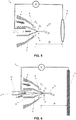
Fig. 6 : Alternative configuration of introduction of the samples, through a capillary through which a carrier liquid flows, and which discharges into the liquid forming a defined and focused current. - Different examples of preferred embodiments of the present invention are shown in
Figures 1-6 herein. In said Figures, it is seen how the sample (1) transport and analysis device of the invention preferably comprises a transport liquid capillary (3) configured to receive transport liquid (2) (or liquid matrix), configured with an outlet section (4) for forming a stable conical capillary meniscus (10), from which emerges a microscopic capillary jet (11) which remains stable and stationary, and which is a vehicle of the samples (1) which have been Introduced into the transport liquid (2) previously. To achieve this effect, the device further comprises a nozzle (5) or funnel arranged concentrically and externally to the transport liquid capillary (3), wherein said nozzle (5) comprises a discharge section (6). The space between the transport liquid capillary (3) and the nozzle (5) is configured to house a stabilizing gas (9). - The device further comprises at least one first electrode (7) for connecting a voltage to the transport liquid (2), and a second opposite electrode (8) arranged at the outlet of the transport liquid capillary (3) and the nozzle (5), wherein said electrodes (7, 8) are subjected to an electrical potential difference (V).
- In different preferred embodiments of the invention, the second electrode (8) opposite to the electrode (7) connected to the transport liquid (2) may be, for example, a flat electrode (
Fig. 1 ), a conical electrode (Fig. 4 ), or a circular or annular electrode (Fig. 5 ). Other electrode forms are equally feasible within the scope of the invention. - The samples (1) to be transported are preferably housed or introduced by the transport capillary (3) (
Figures 1 ,4 and5 ). However, in other preferred embodiments of the invention (Fig. 6 ), the device may comprise a sample housing capillary (12), concentric and internal to the transport liquid capillary (3), configured to house a liquid (13) carrying said samples (1). - Another object of the invention relates to a process for the transport of biological or other samples and for analysis by interaction with a pulsed and focused beam of energy (for example by means of X-rays). Said method preferably comprises carrying out the following steps:
- The samples (1) are introduced into a conveying liquid or matrix (2), which is forced to flow continuously through a transport liquid capillary (3) whose outlet section (4), with diameter D1, is concentrically surrounded by a funnel or nozzle (5).
- The end (4) of the transport liquid capillary (3) exceeds a distance of no more than five times the diameter of the discharge section (6) from said nozzle (5).
- Given the following physical properties of the transport liquid (2): surface tension σ with either its vapor or vacuum, electric conductivity κ, density p and electrical permittivity of vacuum εo , the reference velocity of said transport liquid (2) expressed as

- Given the liquid viscosity µ , the
reference length 
- A first electrode (7) is connected to the transport liquid (2), and another planar electrode (8) is placed in front of the outlet of the capillary at a distance H, and a potential difference V between both of them is established between 1 and 4 times the voltage

- a flow of transport liquid (2) is forced through the transport liquid capillary (3) equal to or less than 100000 times the reference flow expressed as

- A stream of stabilizing gas (9) is discharged concentrically with the transport liquid (2) through the nozzle (5);
- given the density of the gas ρg , the speed of the gas νg , and the opening diameter Dg of said discharge section, the Reynolds number

- Under all of the above conditions, the transport liquid (2) forms at the outlet section (4) of the transport liquid capillary (3) a stable conical capillary meniscus (10) from the apex of which emerges a microscopic capillary jet (11) which remains stable and stationary, and is a vehicle of the samples (1) which have been introduced into the transport liquid (2) previously.
- Preferably, the samples (1) are introduced into the transport liquid (2) by suspension, solution, or emulsion either directly or by previously introducing them into another liquid which is subsequently mixed or emulsified in the transport liquid (2).
- In another embodiment of the method of the invention, the samples (1) are introduced continuously into the transport liquid (2) flowing through the transport liquid capillary (3), by means of a sample housing capillary (12) discharging the sample carrying liquid (13) inside the transport liquid capillary (3).
- In another embodiment of the method of the invention, a defined and convergent stream of the sample carrier liquid (13) is generated which finally flows coaxially through the interior of the microscopic capillary jet (11) drawn by the transport liquid (2).
| (1) | Samples |
| (2) | Transport liquid or matrix |
| (3) | Transport liquid capillary |
| (4) | Capillary outlet section |
| (5) | Stabilizing gas funnel or nozzle |
| (6) | Discharge section of funnel or nozzle |
| (7) | First voltage connection electrode to transport liquid |
| (8) | Second electrode opposite to the liquid, with which a difference of electric potential (V) is established |
| (9) | Stabilizing gas |
| (10) | Stable conical capillary meniscus |
| (11) | Microscopic stable capillary jet |
| (12) | Sample housing capillary |
| (13) | Sample carrier liquid |
Claims (13)
- Device for the transport of biological or other samples and for analysis by interaction with a pulsed and focused energy beam,
characterized in that it comprises:- a transport liquid capillary (3) configured to receive transport liquid (2) or matrix, configured with an outlet section (4);- a nozzle (5) disposed concentrically and externally to the transport liquid capillary (3), wherein said nozzle (5) comprises a discharge section (6); and wherein the space between the transport liquid capillary (3) and the nozzle (5) is configured to house a stabilizing gas (9);- at least one first electrode (7) for connecting a voltage to the transport liquid (2), connected to a second opposite electrode (8) arranged at the outlet of the transport liquid capillary (3) and the nozzle (5), wherein said electrodes (7, 8) are subjected to an electrical potential difference (V) which produces an electric field on the liquid emerging from the outlet section (4) sufficient to stretch it in the shape of a conical meniscus (known as a Taylor cone). - Device according to the preceding claim, wherein the second electrode (8) opposite to the first electrode (7) connected to the transport liquid (2) comprises a flat electrode, an annular or circular electrode and/or a conical electrode.
- Device according to any one of the preceding claims, further comprising a sample housing capillary (12), concentric and internal to the transport liquid capillary (3), configured to house a liquid (13) carrying said samples (1).
- Device according to any one of the preceding claims, wherein the outlet section (4) of the transport liquid capillary (3) exceeds the discharge section (6) of the nozzle (5) by a distance not exceeding five times the diameter of said discharge section (6).
- Method for the transport of biological or other samples and for analysis by interaction with a pulsed and focused beam of energy,
characterized in that it comprises the use of a device according to any one of the preceding claims, and carrying out at least the following steps:- the samples (1) are introduced into a transport liquid (2) or matrix, which is forced to flow continuously through the transport liquid capillary (3) whose outlet section (4), with diameter Dl, is concentrically surrounded by a funnel or nozzle (5).- the outlet section (4) of the transport liquid capillary (3) exceeds the discharge section (6) of the nozzle (5) by a distance of not more than five times the diameter of said discharge section (6);- given the following physical properties of the transport liquid (2): surface tension σ with either its vapor or vacuum, electric conductivity κ, density ρ and electrical permittivity of vacuum εo , the reference velocity of said transport liquid (2) expressed as - given the viscosity µ of the transport liquid (2), the reference length
 - a first electrode (7) is connected to the transport liquid (2), and a second electrode (8) is placed in front of the outlet section (4) of the capillary at a distance H, and a potential difference V between both is produced which produces an electric field on the liquid (2) emerging from the outlet section (4) equivalent to that produced by a planar electrode located at a distance H' when the potential difference V applied is between 1 and 4 times the voltage
 - a flow of liquid (2) is forced through the transport liquid capillary (3) equal to or less than 100000 times the reference flow expressed as
 - a stabilizing gas stream (9) is discharged concentrically with the transport liquid (2) through the nozzle (5);- given the density of the gas ρg , the speed of the gas νg , and the opening diameter Dg of said discharge section, the Reynolds number
 - under all of the foregoing conditions the liquid (2) forms at the outlet section (4) of the transport liquid capillary (3) a stable conical capillary meniscus (10) from the apex of which emerges a steady and stable microscopic capillary jet (11) that is a vehicle of the samples (1) previously introduced into the transport liquid (2).
 - Method according to the preceding claim, wherein the reference velocity of said transport liquid (2) expressed as

- Method according to any of the claims 5-6, wherein a potential difference V is established between the electrodes (7, 8) producing an electric field on the transport liquid (2) emerging from the outlet section (4) equivalent to that which would produce a flat electrode located at a distance H' when the potential difference V applied is between 1 and 4 times the voltage

- Method according to any of claims 5-7, wherein a flow of transport liquid (2) through the transport liquid capillary (3) is less than 500 times the reference flow expressed as

- Method according to any of the claims 5-8, wherein in said discharge section (6), the Reynolds number

- Method according to any of claims 5-9, wherein, given the viscosity µ, of the transport liquid (2), the length

- Method according to any one of claims 5-10, wherein the samples (1) are introduced into the liquid (2) by suspension, solution, or emulsion either directly or by introducing them previously into another liquid which is subsequently mixed or emulsified in the matrix liquid (1).
- Method according to any one of claims 5-11, wherein the samples (1) are continuously introduced into the liquid (2) flowing through the capillary (3), by means of a sample housing capillary (12) discharging the sample carrier liquid (13) inside the capillary (3).
- Method according to any of claims 5-12, wherein a defined and convergent stream of the sample carrier liquid (13) is finally generated flowing coaxially through the interior of the microscopic capillary jet (11) entrained by the transport liquid (2) .
Priority Applications (3)
| Application Number | Priority Date | Filing Date | Title |
|---|---|---|---|
| EP17382333.7A EP3409373B1 (en) | 2017-06-02 | 2017-06-02 | Device and method for the production of aerodynamically stabilized, electrified microscopic jets for the transport of samples |
| JP2018106433A JP2019049525A (en) | 2017-06-02 | 2018-06-01 | Device and method for production of aerodynamically stabilized, electrified microscopic jets for transporting samples |
| US15/996,225 US20180348091A1 (en) | 2017-06-02 | 2018-06-01 | Device and method for the production of aerodynamically stabilized, electrified microscopic jets for the transport of samples |
Applications Claiming Priority (1)
| Application Number | Priority Date | Filing Date | Title |
|---|---|---|---|
| EP17382333.7A EP3409373B1 (en) | 2017-06-02 | 2017-06-02 | Device and method for the production of aerodynamically stabilized, electrified microscopic jets for the transport of samples |
Publications (2)
| Publication Number | Publication Date |
|---|---|
| EP3409373A1 true EP3409373A1 (en) | 2018-12-05 |
| EP3409373B1 EP3409373B1 (en) | 2020-04-15 |
Family
ID=59383524
Family Applications (1)
| Application Number | Title | Priority Date | Filing Date |
|---|---|---|---|
| EP17382333.7A Active EP3409373B1 (en) | 2017-06-02 | 2017-06-02 | Device and method for the production of aerodynamically stabilized, electrified microscopic jets for the transport of samples |
Country Status (3)
| Country | Link |
|---|---|
| US (1) | US20180348091A1 (en) |
| EP (1) | EP3409373B1 (en) |
| JP (1) | JP2019049525A (en) |
Cited By (1)
| Publication number | Priority date | Publication date | Assignee | Title |
|---|---|---|---|---|
| SE2030180A1 (en) * | 2020-06-02 | 2021-12-03 | Braenden Gisela | Liquid sample delivery device |
Families Citing this family (3)
| Publication number | Priority date | Publication date | Assignee | Title |
|---|---|---|---|---|
| JP7332361B2 (en) * | 2019-06-28 | 2023-08-23 | 株式会社アルバック | Freeze-drying nozzle, freeze-drying apparatus, and granulation method |
| CN113588697B (en) * | 2021-08-04 | 2024-04-19 | 中国科学院上海应用物理研究所 | High-viscosity extrusion injection sample loading device for protein crystal structure analysis |
| CN116387962B (en) * | 2023-04-14 | 2026-04-17 | 上海科技大学 | Liquid thin-film sample introduction system and method for X-ray free-electron laser experiments |
Citations (4)
| Publication number | Priority date | Publication date | Assignee | Title |
|---|---|---|---|---|
| WO1998056894A1 (en) * | 1997-06-12 | 1998-12-17 | Regents Of The University Of Minnesota | Electrospraying apparatus and method for introducing material into cells |
| US6147345A (en) * | 1997-10-07 | 2000-11-14 | Chem-Space Associates | Method and apparatus for increased electrospray ion production |
| WO2003041869A1 (en) * | 2001-11-14 | 2003-05-22 | CARBOTEC Gesellschaft für instrumentelle Analytik mbH | Focussed electrospray device |
| US20130308756A1 (en) * | 2012-05-16 | 2013-11-21 | The Board Of Trustees Of The Leland Stanford Junior University | Apparatus and Method for Nanoflow Liquid Jet and Serial Femtosecond X-ray Protein Crystallography |
-
2017
- 2017-06-02 EP EP17382333.7A patent/EP3409373B1/en active Active
-
2018
- 2018-06-01 JP JP2018106433A patent/JP2019049525A/en active Pending
- 2018-06-01 US US15/996,225 patent/US20180348091A1/en not_active Abandoned
Patent Citations (4)
| Publication number | Priority date | Publication date | Assignee | Title |
|---|---|---|---|---|
| WO1998056894A1 (en) * | 1997-06-12 | 1998-12-17 | Regents Of The University Of Minnesota | Electrospraying apparatus and method for introducing material into cells |
| US6147345A (en) * | 1997-10-07 | 2000-11-14 | Chem-Space Associates | Method and apparatus for increased electrospray ion production |
| WO2003041869A1 (en) * | 2001-11-14 | 2003-05-22 | CARBOTEC Gesellschaft für instrumentelle Analytik mbH | Focussed electrospray device |
| US20130308756A1 (en) * | 2012-05-16 | 2013-11-21 | The Board Of Trustees Of The Leland Stanford Junior University | Apparatus and Method for Nanoflow Liquid Jet and Serial Femtosecond X-ray Protein Crystallography |
Non-Patent Citations (6)
| Title |
|---|
| A. M. GANAN-CALVO: "Generation of Steady Liquid Microthreads and Micron-Sized Monodisperse Sprays in Gas Streams", PHYS. REV. LETT., vol. 80, 1998, pages 285 - 288, XP000700168, DOI: doi:10.1103/PhysRevLett.80.285 |
| D. P. DEPONTE; K. NASS; F. STELLATO; M. LIANG; H. N. CHAPMAN: "Sample Injection for Pulsed X-ray Sources", SPIE, PO BOX 10 BELLINGHAM WA 98227-0010, USA, 27 May 2011 (2011-05-27), XP040559704 * |
| D.P. DE PONTE; U. WEIERSTALL; K. SCHMIDT; J. WARNER; D.STARODUB; J.C.H. SPENCE; R.B. DOAK: "Gas dynamic virtual nozzle for generation of microscopic droplet streams", J. PHYS. D: APPL. PHYS., vol. 41, 2008, pages 195505, XP020140896, DOI: doi:10.1088/0022-3727/41/19/195505 |
| DEPONTE D P ET AL: "Gas dynamic virtual nozzle for generation of microscopic droplet streams; Gas dynamic nozzle", JOURNAL OF PHYSICS D: APPLIED PHYSICS, INSTITUTE OF PHYSICS PUBLISHING LTD, GB, vol. 41, no. 19, 7 October 2008 (2008-10-07), pages 195505, XP020140896, ISSN: 0022-3727, DOI: 10.1088/0022-3727/41/19/195505 * |
| H. CHAPMAN ET AL.: "Femtosecond X-ray protein nanocrystallography", NATURE, vol. 470, 2011, pages 73 - 78 |
| U. WEIERSTALL ET AL.: "Lipidic Cubic Phase Injector Facilitates Membrane Protein Serial Femtosecond Crystallography", NATURE COMM., vol. 5, no. 1-6, 2014, pages 3309 |
Cited By (2)
| Publication number | Priority date | Publication date | Assignee | Title |
|---|---|---|---|---|
| SE2030180A1 (en) * | 2020-06-02 | 2021-12-03 | Braenden Gisela | Liquid sample delivery device |
| SE544493C2 (en) * | 2020-06-02 | 2022-06-21 | Serial X Ab | Liquid sample delivery device |
Also Published As
| Publication number | Publication date |
|---|---|
| US20180348091A1 (en) | 2018-12-06 |
| EP3409373B1 (en) | 2020-04-15 |
| JP2019049525A (en) | 2019-03-28 |
Similar Documents
| Publication | Publication Date | Title |
|---|---|---|
| EP3409373B1 (en) | Device and method for the production of aerodynamically stabilized, electrified microscopic jets for the transport of samples | |
| DE10084713B3 (en) | A charge-adjusted aerosol generating system, a method of ionizing an aerosol, a method of identifying a nonvolatile material, and a corona discharge aerosol landing adjustment device | |
| Gañán-Calvo et al. | A novel pneumatic technique to generate steady capillary microjets | |
| Gamero-Castaño et al. | Electric measurements of charged sprays emitted by cone-jets | |
| Si et al. | Modes in flow focusing and instability of coaxial liquid–gas jets | |
| US9275844B2 (en) | Apparatus and method for nanoflow liquid jet and serial femtosecond x-ray protein crystallography | |
| US5247842A (en) | Electrospray apparatus for producing uniform submicrometer droplets | |
| Bateman et al. | Anthropogenic influences on the physical state of submicron particulate matter over a tropical forest | |
| Van Deynse et al. | Surface activation of polyethylene with an argon atmospheric pressure plasma jet: Influence of applied power and flow rate | |
| US9520278B2 (en) | Nebulizer and analyzer | |
| Jaworek et al. | Low temperature plasmas and electrosprays | |
| EP2716139B1 (en) | Device and method for producing a cold, homogeneous plasma under atmospheric pressure conditions | |
| DE112014001615T5 (en) | Apparatus and method for liquid sample introduction | |
| DE112014001620T5 (en) | Apparatus and method for mixing a liquid sample to be introduced into an analyzer | |
| Acero et al. | Focusing liquid microjets with nozzles | |
| Kourmatzis et al. | Combined effervescent and airblast atomization of a liquid jet | |
| DE102009037716A1 (en) | High-pressure atmospheric pressure ion source for vacuum ion spectrometer | |
| Javanmard et al. | Comparison of characteristics of atmospheric pressure plasma jets using argon and helium working gases | |
| DE3310551C2 (en) | Particle examination device for the examination of particles suspended in a liquid | |
| Agostinho et al. | Monodisperse water microdroplets generated by electrohydrodynamic atomization in the simple-jet mode | |
| WO2020100761A1 (en) | Plasma torch, plasma generator, and analysis device | |
| Khan et al. | Processing laser ablated plasmonic nanoparticle aerosols with nonthermal dielectric barrier discharge jets of argon and helium and plasma induced effects | |
| Xu et al. | Aerosol static electrification and its effects in inductively coupled plasma spectroscopy | |
| Wu et al. | Dual-stream of monodisperse droplet generator | |
| Zheng et al. | Controlled Crystallization of Sodium Chloride Nanocrystals in Microdroplets Produced by Electrospray from an Ultra‐Dilute Solution |
Legal Events
| Date | Code | Title | Description |
|---|---|---|---|
| PUAI | Public reference made under article 153(3) epc to a published international application that has entered the european phase |
Free format text: ORIGINAL CODE: 0009012 |
|
| STAA | Information on the status of an ep patent application or granted ep patent |
Free format text: STATUS: THE APPLICATION HAS BEEN PUBLISHED |
|
| AK | Designated contracting states |
Kind code of ref document: A1 Designated state(s): AL AT BE BG CH CY CZ DE DK EE ES FI FR GB GR HR HU IE IS IT LI LT LU LV MC MK MT NL NO PL PT RO RS SE SI SK SM TR |
|
| AX | Request for extension of the european patent |
Extension state: BA ME |
|
| STAA | Information on the status of an ep patent application or granted ep patent |
Free format text: STATUS: REQUEST FOR EXAMINATION WAS MADE |
|
| 17P | Request for examination filed |
Effective date: 20190605 |
|
| RBV | Designated contracting states (corrected) |
Designated state(s): AL AT BE BG CH CY CZ DE DK EE ES FI FR GB GR HR HU IE IS IT LI LT LU LV MC MK MT NL NO PL PT RO RS SE SI SK SM TR |
|
| GRAP | Despatch of communication of intention to grant a patent |
Free format text: ORIGINAL CODE: EPIDOSNIGR1 |
|
| STAA | Information on the status of an ep patent application or granted ep patent |
Free format text: STATUS: GRANT OF PATENT IS INTENDED |
|
| RIC1 | Information provided on ipc code assigned before grant |
Ipc: G01N 23/20008 20180101ALI20190919BHEP Ipc: B05B 7/06 20060101ALI20190919BHEP Ipc: B05B 5/025 20060101AFI20190919BHEP |
|
| INTG | Intention to grant announced |
Effective date: 20191015 |
|
| GRAS | Grant fee paid |
Free format text: ORIGINAL CODE: EPIDOSNIGR3 |
|
| GRAA | (expected) grant |
Free format text: ORIGINAL CODE: 0009210 |
|
| STAA | Information on the status of an ep patent application or granted ep patent |
Free format text: STATUS: THE PATENT HAS BEEN GRANTED |
|
| AK | Designated contracting states |
Kind code of ref document: B1 Designated state(s): AL AT BE BG CH CY CZ DE DK EE ES FI FR GB GR HR HU IE IS IT LI LT LU LV MC MK MT NL NO PL PT RO RS SE SI SK SM TR |
|
| REG | Reference to a national code |
Ref country code: CH Ref legal event code: EP |
|
| REG | Reference to a national code |
Ref country code: DE Ref legal event code: R096 Ref document number: 602017014761 Country of ref document: DE |
|
| REG | Reference to a national code |
Ref country code: IE Ref legal event code: FG4D |
|
| REG | Reference to a national code |
Ref country code: AT Ref legal event code: REF Ref document number: 1256630 Country of ref document: AT Kind code of ref document: T Effective date: 20200515 |
|
| REG | Reference to a national code |
Ref country code: SE Ref legal event code: TRGR |
|
| REG | Reference to a national code |
Ref country code: NL Ref legal event code: MP Effective date: 20200415 |
|
| REG | Reference to a national code |
Ref country code: LT Ref legal event code: MG4D |
|
| PG25 | Lapsed in a contracting state [announced via postgrant information from national office to epo] |
Ref country code: NL Free format text: LAPSE BECAUSE OF FAILURE TO SUBMIT A TRANSLATION OF THE DESCRIPTION OR TO PAY THE FEE WITHIN THE PRESCRIBED TIME-LIMIT Effective date: 20200415 Ref country code: FI Free format text: LAPSE BECAUSE OF FAILURE TO SUBMIT A TRANSLATION OF THE DESCRIPTION OR TO PAY THE FEE WITHIN THE PRESCRIBED TIME-LIMIT Effective date: 20200415 Ref country code: IS Free format text: LAPSE BECAUSE OF FAILURE TO SUBMIT A TRANSLATION OF THE DESCRIPTION OR TO PAY THE FEE WITHIN THE PRESCRIBED TIME-LIMIT Effective date: 20200815 Ref country code: GR Free format text: LAPSE BECAUSE OF FAILURE TO SUBMIT A TRANSLATION OF THE DESCRIPTION OR TO PAY THE FEE WITHIN THE PRESCRIBED TIME-LIMIT Effective date: 20200716 Ref country code: NO Free format text: LAPSE BECAUSE OF FAILURE TO SUBMIT A TRANSLATION OF THE DESCRIPTION OR TO PAY THE FEE WITHIN THE PRESCRIBED TIME-LIMIT Effective date: 20200715 Ref country code: PT Free format text: LAPSE BECAUSE OF FAILURE TO SUBMIT A TRANSLATION OF THE DESCRIPTION OR TO PAY THE FEE WITHIN THE PRESCRIBED TIME-LIMIT Effective date: 20200817 Ref country code: LT Free format text: LAPSE BECAUSE OF FAILURE TO SUBMIT A TRANSLATION OF THE DESCRIPTION OR TO PAY THE FEE WITHIN THE PRESCRIBED TIME-LIMIT Effective date: 20200415 |
|
| REG | Reference to a national code |
Ref country code: AT Ref legal event code: MK05 Ref document number: 1256630 Country of ref document: AT Kind code of ref document: T Effective date: 20200415 |
|
| PG25 | Lapsed in a contracting state [announced via postgrant information from national office to epo] |
Ref country code: LV Free format text: LAPSE BECAUSE OF FAILURE TO SUBMIT A TRANSLATION OF THE DESCRIPTION OR TO PAY THE FEE WITHIN THE PRESCRIBED TIME-LIMIT Effective date: 20200415 Ref country code: RS Free format text: LAPSE BECAUSE OF FAILURE TO SUBMIT A TRANSLATION OF THE DESCRIPTION OR TO PAY THE FEE WITHIN THE PRESCRIBED TIME-LIMIT Effective date: 20200415 Ref country code: BG Free format text: LAPSE BECAUSE OF FAILURE TO SUBMIT A TRANSLATION OF THE DESCRIPTION OR TO PAY THE FEE WITHIN THE PRESCRIBED TIME-LIMIT Effective date: 20200715 Ref country code: HR Free format text: LAPSE BECAUSE OF FAILURE TO SUBMIT A TRANSLATION OF THE DESCRIPTION OR TO PAY THE FEE WITHIN THE PRESCRIBED TIME-LIMIT Effective date: 20200415 |
|
| PG25 | Lapsed in a contracting state [announced via postgrant information from national office to epo] |
Ref country code: AL Free format text: LAPSE BECAUSE OF FAILURE TO SUBMIT A TRANSLATION OF THE DESCRIPTION OR TO PAY THE FEE WITHIN THE PRESCRIBED TIME-LIMIT Effective date: 20200415 |
|
| REG | Reference to a national code |
Ref country code: DE Ref legal event code: R097 Ref document number: 602017014761 Country of ref document: DE |
|
| PG25 | Lapsed in a contracting state [announced via postgrant information from national office to epo] |
Ref country code: CZ Free format text: LAPSE BECAUSE OF FAILURE TO SUBMIT A TRANSLATION OF THE DESCRIPTION OR TO PAY THE FEE WITHIN THE PRESCRIBED TIME-LIMIT Effective date: 20200415 Ref country code: RO Free format text: LAPSE BECAUSE OF FAILURE TO SUBMIT A TRANSLATION OF THE DESCRIPTION OR TO PAY THE FEE WITHIN THE PRESCRIBED TIME-LIMIT Effective date: 20200415 Ref country code: EE Free format text: LAPSE BECAUSE OF FAILURE TO SUBMIT A TRANSLATION OF THE DESCRIPTION OR TO PAY THE FEE WITHIN THE PRESCRIBED TIME-LIMIT Effective date: 20200415 Ref country code: DK Free format text: LAPSE BECAUSE OF FAILURE TO SUBMIT A TRANSLATION OF THE DESCRIPTION OR TO PAY THE FEE WITHIN THE PRESCRIBED TIME-LIMIT Effective date: 20200415 Ref country code: AT Free format text: LAPSE BECAUSE OF FAILURE TO SUBMIT A TRANSLATION OF THE DESCRIPTION OR TO PAY THE FEE WITHIN THE PRESCRIBED TIME-LIMIT Effective date: 20200415 Ref country code: SM Free format text: LAPSE BECAUSE OF FAILURE TO SUBMIT A TRANSLATION OF THE DESCRIPTION OR TO PAY THE FEE WITHIN THE PRESCRIBED TIME-LIMIT Effective date: 20200415 Ref country code: IT Free format text: LAPSE BECAUSE OF FAILURE TO SUBMIT A TRANSLATION OF THE DESCRIPTION OR TO PAY THE FEE WITHIN THE PRESCRIBED TIME-LIMIT Effective date: 20200415 Ref country code: ES Free format text: LAPSE BECAUSE OF FAILURE TO SUBMIT A TRANSLATION OF THE DESCRIPTION OR TO PAY THE FEE WITHIN THE PRESCRIBED TIME-LIMIT Effective date: 20200415 Ref country code: MC Free format text: LAPSE BECAUSE OF FAILURE TO SUBMIT A TRANSLATION OF THE DESCRIPTION OR TO PAY THE FEE WITHIN THE PRESCRIBED TIME-LIMIT Effective date: 20200415 |
|
| PLBE | No opposition filed within time limit |
Free format text: ORIGINAL CODE: 0009261 |
|
| STAA | Information on the status of an ep patent application or granted ep patent |
Free format text: STATUS: NO OPPOSITION FILED WITHIN TIME LIMIT |
|
| PG25 | Lapsed in a contracting state [announced via postgrant information from national office to epo] |
Ref country code: SK Free format text: LAPSE BECAUSE OF FAILURE TO SUBMIT A TRANSLATION OF THE DESCRIPTION OR TO PAY THE FEE WITHIN THE PRESCRIBED TIME-LIMIT Effective date: 20200415 Ref country code: PL Free format text: LAPSE BECAUSE OF FAILURE TO SUBMIT A TRANSLATION OF THE DESCRIPTION OR TO PAY THE FEE WITHIN THE PRESCRIBED TIME-LIMIT Effective date: 20200415 |
|
| 26N | No opposition filed |
Effective date: 20210118 |
|
| PG25 | Lapsed in a contracting state [announced via postgrant information from national office to epo] |
Ref country code: LU Free format text: LAPSE BECAUSE OF NON-PAYMENT OF DUE FEES Effective date: 20200602 |
|
| REG | Reference to a national code |
Ref country code: BE Ref legal event code: MM Effective date: 20200630 |
|
| PG25 | Lapsed in a contracting state [announced via postgrant information from national office to epo] |
Ref country code: IE Free format text: LAPSE BECAUSE OF NON-PAYMENT OF DUE FEES Effective date: 20200602 |
|
| PG25 | Lapsed in a contracting state [announced via postgrant information from national office to epo] |
Ref country code: BE Free format text: LAPSE BECAUSE OF NON-PAYMENT OF DUE FEES Effective date: 20200630 Ref country code: SI Free format text: LAPSE BECAUSE OF FAILURE TO SUBMIT A TRANSLATION OF THE DESCRIPTION OR TO PAY THE FEE WITHIN THE PRESCRIBED TIME-LIMIT Effective date: 20200415 |
|
| PG25 | Lapsed in a contracting state [announced via postgrant information from national office to epo] |
Ref country code: TR Free format text: LAPSE BECAUSE OF FAILURE TO SUBMIT A TRANSLATION OF THE DESCRIPTION OR TO PAY THE FEE WITHIN THE PRESCRIBED TIME-LIMIT Effective date: 20200415 Ref country code: MT Free format text: LAPSE BECAUSE OF FAILURE TO SUBMIT A TRANSLATION OF THE DESCRIPTION OR TO PAY THE FEE WITHIN THE PRESCRIBED TIME-LIMIT Effective date: 20200415 Ref country code: CY Free format text: LAPSE BECAUSE OF FAILURE TO SUBMIT A TRANSLATION OF THE DESCRIPTION OR TO PAY THE FEE WITHIN THE PRESCRIBED TIME-LIMIT Effective date: 20200415 |
|
| REG | Reference to a national code |
Ref country code: DE Ref legal event code: R081 Ref document number: 602017014761 Country of ref document: DE Owner name: DEUTSCHES ELEKTRONEN-SYNCHROTRON DESY, DE Free format text: FORMER OWNERS: DEUTSCHES ELEKTRONEN-SYNCHROTRON DESY, 22607 HAMBURG, DE; UNIVERSIDAD DE SEVILLA, SEVILLA, ES |
|
| PG25 | Lapsed in a contracting state [announced via postgrant information from national office to epo] |
Ref country code: MK Free format text: LAPSE BECAUSE OF FAILURE TO SUBMIT A TRANSLATION OF THE DESCRIPTION OR TO PAY THE FEE WITHIN THE PRESCRIBED TIME-LIMIT Effective date: 20200415 |
|
| REG | Reference to a national code |
Ref country code: GB Ref legal event code: 732E Free format text: REGISTERED BETWEEN 20220623 AND 20220629 |
|
| PGFP | Annual fee paid to national office [announced via postgrant information from national office to epo] |
Ref country code: FR Payment date: 20230626 Year of fee payment: 7 |
|
| PGFP | Annual fee paid to national office [announced via postgrant information from national office to epo] |
Ref country code: SE Payment date: 20230627 Year of fee payment: 7 |
|
| PGFP | Annual fee paid to national office [announced via postgrant information from national office to epo] |
Ref country code: GB Payment date: 20230627 Year of fee payment: 7 Ref country code: CH Payment date: 20230702 Year of fee payment: 7 |
|
| PGFP | Annual fee paid to national office [announced via postgrant information from national office to epo] |
Ref country code: DE Payment date: 20240617 Year of fee payment: 8 |
|
| REG | Reference to a national code |
Ref country code: SE Ref legal event code: EUG |
|
| REG | Reference to a national code |
Ref country code: CH Ref legal event code: PL |
|
| GBPC | Gb: european patent ceased through non-payment of renewal fee |
Effective date: 20240602 |
|
| PG25 | Lapsed in a contracting state [announced via postgrant information from national office to epo] |
Ref country code: CH Free format text: LAPSE BECAUSE OF NON-PAYMENT OF DUE FEES Effective date: 20240630 |
|
| PG25 | Lapsed in a contracting state [announced via postgrant information from national office to epo] |
Ref country code: FR Free format text: LAPSE BECAUSE OF NON-PAYMENT OF DUE FEES Effective date: 20240630 |
|
| PG25 | Lapsed in a contracting state [announced via postgrant information from national office to epo] |
Ref country code: GB Free format text: LAPSE BECAUSE OF NON-PAYMENT OF DUE FEES Effective date: 20240602 |
|
| PG25 | Lapsed in a contracting state [announced via postgrant information from national office to epo] |
Ref country code: SE Free format text: LAPSE BECAUSE OF NON-PAYMENT OF DUE FEES Effective date: 20240603 |
|
| REG | Reference to a national code |
Ref country code: DE Ref legal event code: R119 Ref document number: 602017014761 Country of ref document: DE |
|
| PG25 | Lapsed in a contracting state [announced via postgrant information from national office to epo] |
Ref country code: DE Free format text: LAPSE BECAUSE OF NON-PAYMENT OF DUE FEES Effective date: 20260101 |