EP3407689A1 - Rack mounting system - Google Patents
Rack mounting system Download PDFInfo
- Publication number
- EP3407689A1 EP3407689A1 EP17206376.0A EP17206376A EP3407689A1 EP 3407689 A1 EP3407689 A1 EP 3407689A1 EP 17206376 A EP17206376 A EP 17206376A EP 3407689 A1 EP3407689 A1 EP 3407689A1
- Authority
- EP
- European Patent Office
- Prior art keywords
- rack
- connecting assembly
- chassis
- width
- mounting
- Prior art date
- Legal status (The legal status is an assumption and is not a legal conclusion. Google has not performed a legal analysis and makes no representation as to the accuracy of the status listed.)
- Granted
Links
Images



Classifications
-
- H—ELECTRICITY
- H05—ELECTRIC TECHNIQUES NOT OTHERWISE PROVIDED FOR
- H05K—PRINTED CIRCUITS; CASINGS OR CONSTRUCTIONAL DETAILS OF ELECTRIC APPARATUS; MANUFACTURE OF ASSEMBLAGES OF ELECTRICAL COMPONENTS
- H05K7/00—Constructional details common to different types of electric apparatus
- H05K7/14—Mounting supporting structure in casing or on frame or rack
- H05K7/1485—Servers; Data center rooms, e.g. 19-inch computer racks
- H05K7/1488—Cabinets therefor, e.g. chassis or racks or mechanical interfaces between blades and support structures
- H05K7/1489—Cabinets therefor, e.g. chassis or racks or mechanical interfaces between blades and support structures characterized by the mounting of blades therein, e.g. brackets, rails, trays
-
- A—HUMAN NECESSITIES
- A47—FURNITURE; DOMESTIC ARTICLES OR APPLIANCES; COFFEE MILLS; SPICE MILLS; SUCTION CLEANERS IN GENERAL
- A47B—TABLES; DESKS; OFFICE FURNITURE; CABINETS; DRAWERS; GENERAL DETAILS OF FURNITURE
- A47B88/00—Drawers for tables, cabinets or like furniture; Guides for drawers
- A47B88/40—Sliding drawers; Slides or guides therefor
- A47B88/407—Adjustably or detachably mounted drawers
-
- A—HUMAN NECESSITIES
- A47—FURNITURE; DOMESTIC ARTICLES OR APPLIANCES; COFFEE MILLS; SPICE MILLS; SUCTION CLEANERS IN GENERAL
- A47B—TABLES; DESKS; OFFICE FURNITURE; CABINETS; DRAWERS; GENERAL DETAILS OF FURNITURE
- A47B88/00—Drawers for tables, cabinets or like furniture; Guides for drawers
- A47B88/40—Sliding drawers; Slides or guides therefor
- A47B88/423—Fastening devices for slides or guides
Definitions
- the present invention is related to a rack mounting system.
- a rack has a first side and a second side defining a rack width.
- a rack mounting system comprises at least one pair of connecting assemblies, such as rail members, respectively mounted at two sides of the rack in order to mount a chassis to the rack.
- the current rack mounting system can only to be applied to a rack and a chassis comply with the same specification. Once specifications or sizes of the rack and the chassis do not match, the chassis cannot be mounted to the rack.
- the present invention aims at providing a rack mounting system.
- the rack mounting system is applicable to a rack.
- the rack mounting system comprises a mounting mechanism, a first connecting assembly and a second connecting assembly.
- the mounting mechanism is configured to be detachably mounted to a first side of the rack, and movable relative to the first side of the rack.
- the first connecting assembly is configured to be detachably mounted to a second side of the rack.
- the second connecting assembly is connected to the mounting mechanism.
- the first connecting assembly and the second connecting assembly are configured to carry a first chassis with a first chassis width when the mounting mechanism is moved to a first position relative to the first side of the rack.
- the claimed rack mounting system comprises a first connecting assembly, a second connecting assembly and a mounting mechanism.
- the first connecting assembly is configured to be connected to a first side of a chassis.
- the second connecting assembly is configured to be connected to a second side of the chassis.
- the mounting mechanism is connected to the second connecting assembly. Wherein, when the mounting mechanism is mounted to a first side of a first rack and the first connecting assembly is mounted to a second side of the first rack, the mounting mechanism is configured to inwardly extend a first mounting length from the first side of the first rack in order to mount the chassis to the first rack.
- the first rack has a first rack width.
- the mounting mechanism when the mounting mechanism is mounted to a first side of a second rack and the first connecting assembly is mounted to a second side of the second rack, the mounting mechanism is configured to inwardly extend a second mounting length from the first side of the second rack in order to mount the chassis to the second rack.
- the second rack has a second rack width different from the first rack width.
- the claimed rack system comprises a rack, a mounting mechanism, a first connecting assembly and a second connecting assembly.
- the rack has a first side and a second side.
- the mounting mechanism is detachably mounted to the first side of the rack.
- the first connecting assembly is detachably mounted to the second side of the rack.
- the second connecting assembly is connected to the mounting mechanism.
- the first connecting assembly and the second connecting assembly are configured to mount a first chassis with a first chassis width to the rack when the mounting mechanism is located at a first position relative to the first side of the rack.
- first connecting assembly and the second connecting assembly are configured to mount a second chassis with a second chassis width to the rack when the mounting mechanism is located at an extension position relative to the first side of the rack.
- the extension position is different from the first position.
- the second chassis width is different from the first chassis width.
- a rack mounting system is applicable to a first rack 10.
- the first rack 10 has a plurality of posts, such as a first post 12a, a second post 12b, a third post 12c and a fourth post 12d.
- the first post 12a and the second post 12b are defined as a first side S1 of the first rack 10
- the third post 12c and the fourth post 12d are defined as a second side S2 of the first rack 10
- a first rack width R1 is defined between the first side S1 and the second side S2 of the first rack 10.
- the rack mounting system comprises a mounting mechanism 14, a first connecting assembly 16 and a second connecting assembly 18.
- the mounting mechanism 14 is detachably mounted to one of the first side S1 and the second side S2 of the first rack 10.
- the mounting mechanism 14 comprises two separated components respectively detachably mounted to the first post 12a and the second post 12b of the first rack 10. That is, the mounting mechanism 14 is detachably mounted to the first side S1 of the first rack 10.
- the mounting mechanism 14 can be a single component detachably mounted to the first post 12a and the second post 12b of the first rack 10, but the present invention is not limited thereto.
- the first connecting assembly 16 is detachably mounted to the other one of the first side S1 and the second side S2 of the first rack 10.
- the first connecting assembly 16 is detachably mounted to the second side S2 of the first rack 10.
- the second connecting assembly 18 is connected to the mounting mechanism 14.
- a first chassis width C1 is defined between the first connecting assembly 16 and the second connecting assembly 18.
- a first chassis 20 with the first chassis width C1 can be mounted to the first connecting assembly 16 and the second connecting assembly 18.
- the first connecting assembly 16 can be connected to a first side of the first chassis 20, and the second connecting assembly 18 can be connected to a second side of the first chassis 20.
- the mounting mechanism 14 inwardly extends a first mounting length M1 relative to the first side S1 of the first rack 10.
- the first connecting assembly 16 has a first connecting width W1.
- the second connecting assembly 18 has a second connecting width W2.
- the first mounting length M1 is greater than the first connecting width W1 and the second connecting width W2.
- the mounting mechanism 14 (for ease of explanation, structure and adjusting mechanism of the mounting mechanism 14 are simplified in FIG. 2 and FIG. 4 ) can be adjusted to move from a first position P1 to an extension position X1, such that the mounting mechanism 14 inwardly extends an extension length E1 from the first side S1 of the first rack 10 for forming a second chassis width C2 between the first connecting assembly 16 and the second connecting assembly 18, in order to mount a second chassis 22 with the second chassis width C2 to the fist connecting assembly 16 and the second connecting assembly 18.
- the mounting mechanism 14 can be further adjust to mount a chassis with a different chassis width to the first rack 10.
- the mounting mechanism 14 allows the first chassis 20 with the first chassis width C1 and the second chassis 22 with the second chassis width C2 to be mounted to the first rack 10 with the first rack width R1.
- the first connecting assembly 16 comprises a first fixed rail 24, and the second connecting assembly 18 comprises a second fixed rail 25.
- the first fixed rail 24 and the second fixed rail 25 are configured to fixedly mount the first chassis 20 to into the first rack 10.
- specifications of the first fixed rail 24 and the second fixed rail 25 can be identical or different, the present invention is not limited thereto.
- the first connecting assembly 16 comprises the first fixed rail 24 and a first movable rail 26, and the second connecting assembly 18 comprises the second fixed rail 25 and a second movable rail 27.
- the first movable rail 26 and the second movable rail 27 allow the first chassis 20 to be pulled out of the first rack 10.
- specifications of rails of the first connecting assembly 16 and the second connecting assembly 18 can be identical or different, the present invention is not limited thereto.
- the rack mounting system can be also applied to a second rack 30.
- the second rack 30 has a second rack width R2 different from the first rack width R1 of the first rack 10.
- the mounting mechanism 14 can be adjusted to move to a second position P2 relative to a first side S1 of the second rack 30, such that the mounting mechanism 14 inwardly extends a second mounting length M2 (different from the first mounting length M1) from the first side S1 of the second rack 30 for forming the first chassis width C1 between the first connecting assembly 16 and the second connecting assembly 18, in order to mount the first chassis 20 with the first chassis width C1 to the first connecting assembly 16 and the second connecting assembly 18.
- the second mounting length M2 is greater than the first connecting width W1 and the second connecting width W2.
- the first chassis 20 with the first chassis width C1 can be mounted to the first rack 10 with the first rack width R1 as shown in FIG. 2 . Moreover, the first chassis 20 with the first chassis width C1 can also be mounted to the second rack 30 with the second rack width R2 as shown in FIG. 6 .
- the present invention is characterized in that: when the mounting mechanism 14 inwardly extends the first mounting length M1 relative to the first rack 10, the first chassis 20 with the first chassis width C1 can be mounted to the first rack 10 with the first rack width R1; and when the mounting mechanism 14 is adjusted to inwardly extend the second mounting length M2 relative to the second rack 30, the first chassis 20 with the first chassis width C1 can be mounted to the second rack 30 with the second rack width R2.
- the present invention is characterized in that: when the mounting mechanism 14 of the connecting assembly inwardly extends the first mounting length M1 relative to the first rack 10, the first chassis 20 with the first chassis width C1 can be mounted to the first rack 10 with the first rack width R1; and when the mounting mechanism 14 is adjusted to inwardly extends the extension length E1 relative to the first rack 10, the second chassis 22 with the second chassis width C2 can be mounted to the first rack 10 with the first rack width R1.
Landscapes
- Engineering & Computer Science (AREA)
- Computer Hardware Design (AREA)
- General Engineering & Computer Science (AREA)
- Microelectronics & Electronic Packaging (AREA)
- Drawers Of Furniture (AREA)
Abstract
Description
- The present invention is related to a rack mounting system.
- Generally, a rack has a first side and a second side defining a rack width. A rack mounting system comprises at least one pair of connecting assemblies, such as rail members, respectively mounted at two sides of the rack in order to mount a chassis to the rack.
- The current rack mounting system can only to be applied to a rack and a chassis comply with the same specification. Once specifications or sizes of the rack and the chassis do not match, the chassis cannot be mounted to the rack.
- With rapid development of information technology, dimensions (such as a width dimension) of a chassis are getting bigger to accommodate more electronic apparatuses or related components.
US patent number US 9,131,769 B2 - This in mind, the present invention aims at providing a rack mounting system.
- This is achieved by a rack mounting system according to claims 1 and 6, and a rack system according to
claim 10. The dependent claims pertain to corresponding further developments and improvements. - As will be seen more clearly from the detailed description following below, the claimed rack mounting system is applicable to a rack. The rack mounting system comprises a mounting mechanism, a first connecting assembly and a second connecting assembly. The mounting mechanism is configured to be detachably mounted to a first side of the rack, and movable relative to the first side of the rack. The first connecting assembly is configured to be detachably mounted to a second side of the rack. The second connecting assembly is connected to the mounting mechanism. Wherein, the first connecting assembly and the second connecting assembly are configured to carry a first chassis with a first chassis width when the mounting mechanism is moved to a first position relative to the first side of the rack.
- As will be seen more clearly from the detailed description following below, the claimed rack mounting system comprises a first connecting assembly, a second connecting assembly and a mounting mechanism. The first connecting assembly is configured to be connected to a first side of a chassis. The second connecting assembly is configured to be connected to a second side of the chassis. The mounting mechanism is connected to the second connecting assembly. Wherein, when the mounting mechanism is mounted to a first side of a first rack and the first connecting assembly is mounted to a second side of the first rack, the mounting mechanism is configured to inwardly extend a first mounting length from the first side of the first rack in order to mount the chassis to the first rack. The first rack has a first rack width. Wherein, when the mounting mechanism is mounted to a first side of a second rack and the first connecting assembly is mounted to a second side of the second rack, the mounting mechanism is configured to inwardly extend a second mounting length from the first side of the second rack in order to mount the chassis to the second rack. The second rack has a second rack width different from the first rack width.
- As will be seen more clearly from the detailed description following below, the claimed rack system comprises a rack, a mounting mechanism, a first connecting assembly and a second connecting assembly. The rack has a first side and a second side. The mounting mechanism is detachably mounted to the first side of the rack. The first connecting assembly is detachably mounted to the second side of the rack. The second connecting assembly is connected to the mounting mechanism. Wherein, the first connecting assembly and the second connecting assembly are configured to mount a first chassis with a first chassis width to the rack when the mounting mechanism is located at a first position relative to the first side of the rack. Wherein, the first connecting assembly and the second connecting assembly are configured to mount a second chassis with a second chassis width to the rack when the mounting mechanism is located at an extension position relative to the first side of the rack. The extension position is different from the first position. The second chassis width is different from the first chassis width.
- In the following, the invention is further illustrated by way of example, taking reference to the accompanying drawings thereof:
-
FIG. 1 is a diagram showing a portion of a first chassis mounted to one side of a first rack according to an embodiment of the present invention; -
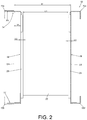
FIG. 2 is a diagram showing the first chassis mounted to the first rack according to an embodiment of the present invention; -
FIG. 3 is a diagram showing a portion of a second chassis mounted to one side of the first rack according to an embodiment of the present invention; -
FIG. 4 is a diagram showing the second chassis mounted to the first rack according to an embodiment of the present invention; -
FIG. 5 is a diagram showing the first chassis being pulled out of the rack according to an embodiment of the present invention; and -
FIG. 6 is a diagram showing the first chassis mounted to a second rack according to an embodiment of the present invention. - As shown in
FIG. 1 andFIG. 2 , a rack mounting system is applicable to afirst rack 10. Thefirst rack 10 has a plurality of posts, such as afirst post 12a, asecond post 12b, athird post 12c and afourth post 12d. Wherein, thefirst post 12a and thesecond post 12b are defined as a first side S1 of thefirst rack 10, thethird post 12c and thefourth post 12d are defined as a second side S2 of thefirst rack 10, and a first rack width R1 is defined between the first side S1 and the second side S2 of thefirst rack 10. - The rack mounting system comprises a
mounting mechanism 14, a first connectingassembly 16 and a second connectingassembly 18. Wherein, themounting mechanism 14 is detachably mounted to one of the first side S1 and the second side S2 of thefirst rack 10. In the present embodiment, themounting mechanism 14 comprises two separated components respectively detachably mounted to thefirst post 12a and thesecond post 12b of thefirst rack 10. That is, themounting mechanism 14 is detachably mounted to the first side S1 of thefirst rack 10. In another embodiment, themounting mechanism 14 can be a single component detachably mounted to thefirst post 12a and thesecond post 12b of thefirst rack 10, but the present invention is not limited thereto. The first connectingassembly 16 is detachably mounted to the other one of the first side S1 and the second side S2 of thefirst rack 10. In the present embodiment, the first connectingassembly 16 is detachably mounted to the second side S2 of thefirst rack 10. In addition, the second connectingassembly 18 is connected to themounting mechanism 14. A first chassis width C1 is defined between thefirst connecting assembly 16 and the second connectingassembly 18. Afirst chassis 20 with the first chassis width C1 can be mounted to thefirst connecting assembly 16 and the second connectingassembly 18. For example, thefirst connecting assembly 16 can be connected to a first side of thefirst chassis 20, and the second connectingassembly 18 can be connected to a second side of thefirst chassis 20. - Preferably, the
mounting mechanism 14 inwardly extends a first mounting length M1 relative to the first side S1 of thefirst rack 10. The first connectingassembly 16 has a first connecting width W1. The second connectingassembly 18 has a second connecting width W2. The first mounting length M1 is greater than the first connecting width W1 and the second connecting width W2. - Please refer to
FIG. 2 to FIG. 4 . Preferably, the mounting mechanism 14 (for ease of explanation, structure and adjusting mechanism of the mountingmechanism 14 are simplified inFIG. 2 andFIG. 4 ) can be adjusted to move from a first position P1 to an extension position X1, such that the mountingmechanism 14 inwardly extends an extension length E1 from the first side S1 of thefirst rack 10 for forming a second chassis width C2 between the first connectingassembly 16 and the second connectingassembly 18, in order to mount asecond chassis 22 with the second chassis width C2 to thefist connecting assembly 16 and the second connectingassembly 18. In another embodiment, the mountingmechanism 14 can be further adjust to mount a chassis with a different chassis width to thefirst rack 10. - Therefore, the mounting
mechanism 14 allows thefirst chassis 20 with the first chassis width C1 and thesecond chassis 22 with the second chassis width C2 to be mounted to thefirst rack 10 with the first rack width R1. - Preferably, the first connecting
assembly 16 comprises a first fixedrail 24, and the second connectingassembly 18 comprises a second fixedrail 25. The first fixedrail 24 and the second fixedrail 25 are configured to fixedly mount thefirst chassis 20 to into thefirst rack 10. Wherein, specifications of the first fixedrail 24 and the second fixedrail 25 can be identical or different, the present invention is not limited thereto. - Preferably, as shown in
FIG. 5 , the first connectingassembly 16 comprises the first fixedrail 24 and a firstmovable rail 26, and the second connectingassembly 18 comprises the second fixedrail 25 and a secondmovable rail 27. The firstmovable rail 26 and the secondmovable rail 27 allow thefirst chassis 20 to be pulled out of thefirst rack 10. Wherein, specifications of rails of the first connectingassembly 16 and the second connectingassembly 18 can be identical or different, the present invention is not limited thereto. - Please refer to
FIG. 6 . Preferably, the rack mounting system can be also applied to asecond rack 30. Thesecond rack 30 has a second rack width R2 different from the first rack width R1 of thefirst rack 10. The mountingmechanism 14 can be adjusted to move to a second position P2 relative to a first side S1 of thesecond rack 30, such that the mountingmechanism 14 inwardly extends a second mounting length M2 (different from the first mounting length M1) from the first side S1 of thesecond rack 30 for forming the first chassis width C1 between the first connectingassembly 16 and the second connectingassembly 18, in order to mount thefirst chassis 20 with the first chassis width C1 to the first connectingassembly 16 and the second connectingassembly 18. The second mounting length M2 is greater than the first connecting width W1 and the second connecting width W2. - Therefore, the
first chassis 20 with the first chassis width C1 can be mounted to thefirst rack 10 with the first rack width R1 as shown inFIG. 2 . Moreover, thefirst chassis 20 with the first chassis width C1 can also be mounted to thesecond rack 30 with the second rack width R2 as shown inFIG. 6 . - According to the aforementioned illustration, the present invention is characterized in that: when the mounting
mechanism 14 inwardly extends the first mounting length M1 relative to thefirst rack 10, thefirst chassis 20 with the first chassis width C1 can be mounted to thefirst rack 10 with the first rack width R1; and when the mountingmechanism 14 is adjusted to inwardly extend the second mounting length M2 relative to thesecond rack 30, thefirst chassis 20 with the first chassis width C1 can be mounted to thesecond rack 30 with the second rack width R2. - In another embodiment, the present invention is characterized in that: when the mounting
mechanism 14 of the connecting assembly inwardly extends the first mounting length M1 relative to thefirst rack 10, thefirst chassis 20 with the first chassis width C1 can be mounted to thefirst rack 10 with the first rack width R1; and when the mountingmechanism 14 is adjusted to inwardly extends the extension length E1 relative to thefirst rack 10, thesecond chassis 22 with the second chassis width C2 can be mounted to thefirst rack 10 with the first rack width R1.
Claims (14)
- A rack mounting system, applicable to a rack (10), the rack mounting system comprising:a mounting mechanism (14) configured to be detachably mounted to a first side of the rack (10), and movable relative to the first side of the rack (10);a first connecting assembly (16) configured to be detachably mounted to a second side of the rack (10); anda second connecting assembly (18) connected to the mounting mechanism (14);wherein the first connecting assembly (16) and the second connecting assembly (18) are configured to carry a first chassis (20) with a first chassis width when the mounting mechanism (14) is moved to a first position relative to the first side of the rack (10).
- The rack mounting system of claim 1, characterized in that the first connecting assembly (16) has a first connecting width, the second connecting assembly (18) has a second connecting width, wherein the mounting mechanism (14) inwardly extends a first mounting length from the first side of the rack (10) when the mounting mechanism (14) is moved to the first position relative to the first side of the rack (10), the first mounting length is greater than the first connecting width and the second connecting width.
- The rack mounting system of claim 1 or 2, characterized in that the first connecting assembly (16) and the second connecting assembly (18) are configured to carry a second chassis (22) with a second chassis width when the mounting mechanism (14) is moved to an extension position from the first position relative to the first side of the rack (10), the second chassis width is different from the first chassis width.
- The rack mounting system of claim 1, characterized in that the first connecting assembly (16) comprises a first fixed rail (24), and the second connecting assembly (18) comprises a second fixed rail (25), the first fixed rail (24) and the second fixed rail (25) are configured to fixedly mount the first chassis (20) with the first chassis width into the rack (10).
- The rack mounting system of claim 1, characterized in that the first connecting assembly (16) comprises a first fixed rail (24) and a first movable rail (26), and the second connecting assembly (18) comprises a second fixed rail (25) and a second movable rail (27), the first movable rail (26) and the second movable rail (27) allow the first chassis (20) with the first chassis width to be pulled out of the rack (10).
- A rack mounting system, comprising:a first connecting assembly (16) configured to be connected to a first side of a chassis (20);a second connecting assembly (18) configured to be connected to a second side of the chassis (20); anda mounting mechanism (14) connected to the second connecting assembly (18);wherein when the mounting mechanism (14) is mounted to a first side of a first rack (10) and the first connecting assembly (16) is mounted to a second side of the first rack (10), the mounting mechanism (14) is configured to inwardly extend a first mounting length from the first side of the first rack (10) in order to mount the chassis (20) to the first rack (10), the first rack (10) has a first rack width;wherein when the mounting mechanism (14) is mounted to a first side of a second rack (30) and the first connecting assembly (16) is mounted to a second side of the second rack (30), the mounting mechanism (14) is configured to inwardly extend a second mounting length from the first side of the second rack (30) in order to mount the chassis (20) to the second rack (30), the second rack (30) has a second rack width different from the first rack width.
- The rack mounting system of claim 6, characterized in that the first connecting assembly (16) has a first connecting width, the second connecting assembly (18) has a second connecting width, the first mounting length is greater than the first connecting width and the second connecting width, the second mounting length is greater than the first connecting width and the second connecting width.
- The rack mounting system of claim 6, characterized in that the first connecting assembly (16) comprises a first fixed rail (24), and the second connecting assembly (18) comprises a second fixed rail (25), the first fixed rail (24) and the second fixed rail (25) are configured to fixedly mount the chassis (20) into the first rack (10) or the second rack (30).
- The rack mounting system of claim 6, characterized in that the first connecting assembly (16) comprises a first fixed rail (24) and a first movable rail (26), and the second connecting assembly (18) comprises a second fixed rail (25) and a second movable rail (27), the first movable rail (26) and the second movable rail (27) allow the chassis (20) to be pulled out of the first rack (10) or the second rack (30).
- A rack system, comprising:a rack (10) having a first side and a second side;a mounting mechanism (14) detachably mount to the first side of the rack (10);a first connecting assembly (16) detachably mount to the second side of the rack (10); anda second connecting assembly (18) connected to the mounting mechanism (14);wherein the first connecting assembly (16) and the second connecting assembly (18) are configured to mount a first chassis (20) with a first chassis width to the rack (10) when the mounting mechanism (14) is located at a first position relative to the first side of the rack (10);wherein the first connecting assembly (16) and the second connecting assembly (18) are configured to mount a second chassis (22) with a second chassis width to the rack (10) when the mounting mechanism (14) is located at an extension position relative to the first side of the rack (10), the extension position is different from the first position, the second chassis width is different from the first chassis width.
- The rack system of claim 10, characterized in that the first connecting assembly (16) has a first connecting width, the second connecting assembly (18) has a second connecting width; wherein the mounting mechanism (14) inwardly extends a first mounting length from the first side of the rack (10) when the mounting mechanism (14) is located at the first position relative to the first side of the rack (10), the first mounting length is greater than the first connecting width and the second connecting width.
- The rack system of claim 10, characterized in that the first connecting assembly (16) comprises a first fixed rail (24), and the second connecting assembly (18) comprises a second fixed rail (25), the first fixed rail (24) and the second fixed rail (25) are configured to fixedly mount the first chassis (20) or the second chassis (22) into the rack (10).
- The rack system of claim 10, characterized in that the first connecting assembly (16) comprises a first fixed rail (24) and a first movable rail (26), and the second connecting assembly (18) comprises a second fixed rail (25) and a second movable rail (27), the first movable rail (26) and the second movable rail (27) allow the first chassis (20) to be pulled out of the rack (10) .
- The rack system of claim 10, characterized in that the first connecting assembly (16) comprises a first fixed rail (24) and a first movable rail (26), and the second connecting assembly (18) comprises a second fixed rail (25) and a second movable rail (27), the first movable rail (26) and the second movable rail (27) allow the second chassis (22) to be pulled out of the rack (10) .
Applications Claiming Priority (1)
| Application Number | Priority Date | Filing Date | Title |
|---|---|---|---|
| TW106118005A TWI624213B (en) | 2017-05-26 | 2017-05-26 | Connecting assembly for rack mounting system |
Publications (2)
| Publication Number | Publication Date |
|---|---|
| EP3407689A1 true EP3407689A1 (en) | 2018-11-28 |
| EP3407689B1 EP3407689B1 (en) | 2022-01-19 |
Family
ID=60654834
Family Applications (1)
| Application Number | Title | Priority Date | Filing Date |
|---|---|---|---|
| EP17206376.0A Active EP3407689B1 (en) | 2017-05-26 | 2017-12-11 | Rack mounting system |
Country Status (4)
| Country | Link |
|---|---|
| US (1) | US20180338614A1 (en) |
| EP (1) | EP3407689B1 (en) |
| JP (1) | JP2018198918A (en) |
| TW (1) | TWI624213B (en) |
Families Citing this family (1)
| Publication number | Priority date | Publication date | Assignee | Title |
|---|---|---|---|---|
| CN112273904A (en) * | 2020-10-28 | 2021-01-29 | 广东库博精密科技有限公司 | Multifunctional adjustable guide rail |
Citations (5)
| Publication number | Priority date | Publication date | Assignee | Title |
|---|---|---|---|---|
| WO2001006293A1 (en) * | 1999-07-15 | 2001-01-25 | Tyco Electronics Raychem Nv | Versatile optical fibre distribution rack |
| US20130016929A1 (en) * | 2011-07-13 | 2013-01-17 | Hon Hai Precision Industry Co., Ltd. | Slide assembly |
| US9089215B1 (en) * | 2014-11-21 | 2015-07-28 | Aic Inc. | Sliding rail assembly |
| US9131769B2 (en) | 2013-09-30 | 2015-09-15 | Fmr Llc | Open bridge rack |
| US20150313036A1 (en) * | 2014-04-25 | 2015-10-29 | Hong Fu Jin Precision Industry (Shenzhen) Co., Ltd. | Cabinet |
Family Cites Families (5)
| Publication number | Priority date | Publication date | Assignee | Title |
|---|---|---|---|---|
| US3133768A (en) * | 1960-01-11 | 1964-05-19 | Markline Electronic Products I | Extensible chassis slide |
| JP4175325B2 (en) * | 2005-01-18 | 2008-11-05 | 日本電気株式会社 | rack |
| TWM442672U (en) * | 2012-06-19 | 2012-12-01 | Caswell Inc | Adjustable type frame structure improvement |
| TWM472383U (en) * | 2013-11-06 | 2014-02-11 | Aic Inc | Industrial computer machine box and its bi-directional sliding track structure |
| JP3191618U (en) * | 2014-04-18 | 2014-07-03 | 川湖科技股▲分▼有限公司 | Slide rail system and connecting device used for the slide rail system |
-
2017
- 2017-05-26 TW TW106118005A patent/TWI624213B/en active
- 2017-11-24 US US15/821,854 patent/US20180338614A1/en not_active Abandoned
- 2017-12-11 EP EP17206376.0A patent/EP3407689B1/en active Active
- 2017-12-18 JP JP2017241277A patent/JP2018198918A/en active Pending
Patent Citations (5)
| Publication number | Priority date | Publication date | Assignee | Title |
|---|---|---|---|---|
| WO2001006293A1 (en) * | 1999-07-15 | 2001-01-25 | Tyco Electronics Raychem Nv | Versatile optical fibre distribution rack |
| US20130016929A1 (en) * | 2011-07-13 | 2013-01-17 | Hon Hai Precision Industry Co., Ltd. | Slide assembly |
| US9131769B2 (en) | 2013-09-30 | 2015-09-15 | Fmr Llc | Open bridge rack |
| US20150313036A1 (en) * | 2014-04-25 | 2015-10-29 | Hong Fu Jin Precision Industry (Shenzhen) Co., Ltd. | Cabinet |
| US9089215B1 (en) * | 2014-11-21 | 2015-07-28 | Aic Inc. | Sliding rail assembly |
Also Published As
| Publication number | Publication date |
|---|---|
| TWI624213B (en) | 2018-05-11 |
| EP3407689B1 (en) | 2022-01-19 |
| TW201902326A (en) | 2019-01-01 |
| JP2018198918A (en) | 2018-12-20 |
| US20180338614A1 (en) | 2018-11-29 |
Similar Documents
| Publication | Publication Date | Title |
|---|---|---|
| EP3143901A1 (en) | Slide rail assembly | |
| EP3154320B1 (en) | Slide rail assembly and bracket device thereof | |
| EP3091823A1 (en) | Cable management assembly | |
| EP3457826B1 (en) | Rack system and slide rail assembly thereof | |
| US9504181B2 (en) | Slide rail assembly | |
| US11147179B2 (en) | Mounting system for mechanical-shock resistant printed circuit board (PCB) | |
| EP3094165A1 (en) | Slide rail assembly | |
| DE102017209584B4 (en) | Mounting structure for an electronics receiving box | |
| US10292496B2 (en) | Bracket device | |
| US10314197B2 (en) | Slide rail assembly for rack system | |
| EP3258755A1 (en) | Rack system | |
| EP3251556A1 (en) | Slide rail and slide rail assembly | |
| EP3258754B1 (en) | Rack system and slide rail assemblies thereof | |
| CN105433616B (en) | Sliding rail assembly | |
| WO2007102086A3 (en) | Configurable chassis guidance system | |
| US20190223314A1 (en) | Rack mounting system | |
| CN108958386B (en) | Sliding rail bracket structure | |
| EP2893838A1 (en) | Adjustable bracket assembly and slide assembly comprising the same | |
| EP3407689B1 (en) | Rack mounting system | |
| CN105813428B (en) | Sliding rail assembly | |
| EP3116291A1 (en) | Slide rail mounting mechanism | |
| EP3005901A1 (en) | Slide rail assembly | |
| EP3758458B1 (en) | Flex board with a spacer | |
| US9367089B2 (en) | Electronic apparatus combined with magnetic attraction force | |
| CN104036800A (en) | Device of tool-free assembly and disassembly for hard disk |
Legal Events
| Date | Code | Title | Description |
|---|---|---|---|
| PUAI | Public reference made under article 153(3) epc to a published international application that has entered the european phase |
Free format text: ORIGINAL CODE: 0009012 |
|
| STAA | Information on the status of an ep patent application or granted ep patent |
Free format text: STATUS: THE APPLICATION HAS BEEN PUBLISHED |
|
| AK | Designated contracting states |
Kind code of ref document: A1 Designated state(s): AL AT BE BG CH CY CZ DE DK EE ES FI FR GB GR HR HU IE IS IT LI LT LU LV MC MK MT NL NO PL PT RO RS SE SI SK SM TR |
|
| AX | Request for extension of the european patent |
Extension state: BA ME |
|
| STAA | Information on the status of an ep patent application or granted ep patent |
Free format text: STATUS: REQUEST FOR EXAMINATION WAS MADE |
|
| 17P | Request for examination filed |
Effective date: 20190108 |
|
| RBV | Designated contracting states (corrected) |
Designated state(s): AL AT BE BG CH CY CZ DE DK EE ES FI FR GB GR HR HU IE IS IT LI LT LU LV MC MK MT NL NO PL PT RO RS SE SI SK SM TR |
|
| STAA | Information on the status of an ep patent application or granted ep patent |
Free format text: STATUS: EXAMINATION IS IN PROGRESS |
|
| 17Q | First examination report despatched |
Effective date: 20200417 |
|
| GRAP | Despatch of communication of intention to grant a patent |
Free format text: ORIGINAL CODE: EPIDOSNIGR1 |
|
| STAA | Information on the status of an ep patent application or granted ep patent |
Free format text: STATUS: GRANT OF PATENT IS INTENDED |
|
| INTG | Intention to grant announced |
Effective date: 20210708 |
|
| GRAS | Grant fee paid |
Free format text: ORIGINAL CODE: EPIDOSNIGR3 |
|
| GRAA | (expected) grant |
Free format text: ORIGINAL CODE: 0009210 |
|
| STAA | Information on the status of an ep patent application or granted ep patent |
Free format text: STATUS: THE PATENT HAS BEEN GRANTED |
|
| AK | Designated contracting states |
Kind code of ref document: B1 Designated state(s): AL AT BE BG CH CY CZ DE DK EE ES FI FR GB GR HR HU IE IS IT LI LT LU LV MC MK MT NL NO PL PT RO RS SE SI SK SM TR |
|
| REG | Reference to a national code |
Ref country code: GB Ref legal event code: FG4D |
|
| REG | Reference to a national code |
Ref country code: CH Ref legal event code: EP |
|
| REG | Reference to a national code |
Ref country code: DE Ref legal event code: R096 Ref document number: 602017052463 Country of ref document: DE |
|
| REG | Reference to a national code |
Ref country code: AT Ref legal event code: REF Ref document number: 1464532 Country of ref document: AT Kind code of ref document: T Effective date: 20220215 |
|
| REG | Reference to a national code |
Ref country code: IE Ref legal event code: FG4D |
|
| REG | Reference to a national code |
Ref country code: LT Ref legal event code: MG9D |
|
| REG | Reference to a national code |
Ref country code: NL Ref legal event code: MP Effective date: 20220119 |
|
| REG | Reference to a national code |
Ref country code: AT Ref legal event code: MK05 Ref document number: 1464532 Country of ref document: AT Kind code of ref document: T Effective date: 20220119 |
|
| PG25 | Lapsed in a contracting state [announced via postgrant information from national office to epo] |
Ref country code: NL Free format text: LAPSE BECAUSE OF FAILURE TO SUBMIT A TRANSLATION OF THE DESCRIPTION OR TO PAY THE FEE WITHIN THE PRESCRIBED TIME-LIMIT Effective date: 20220119 |
|
| PG25 | Lapsed in a contracting state [announced via postgrant information from national office to epo] |
Ref country code: SE Free format text: LAPSE BECAUSE OF FAILURE TO SUBMIT A TRANSLATION OF THE DESCRIPTION OR TO PAY THE FEE WITHIN THE PRESCRIBED TIME-LIMIT Effective date: 20220119 Ref country code: RS Free format text: LAPSE BECAUSE OF FAILURE TO SUBMIT A TRANSLATION OF THE DESCRIPTION OR TO PAY THE FEE WITHIN THE PRESCRIBED TIME-LIMIT Effective date: 20220119 Ref country code: PT Free format text: LAPSE BECAUSE OF FAILURE TO SUBMIT A TRANSLATION OF THE DESCRIPTION OR TO PAY THE FEE WITHIN THE PRESCRIBED TIME-LIMIT Effective date: 20220519 Ref country code: NO Free format text: LAPSE BECAUSE OF FAILURE TO SUBMIT A TRANSLATION OF THE DESCRIPTION OR TO PAY THE FEE WITHIN THE PRESCRIBED TIME-LIMIT Effective date: 20220419 Ref country code: LT Free format text: LAPSE BECAUSE OF FAILURE TO SUBMIT A TRANSLATION OF THE DESCRIPTION OR TO PAY THE FEE WITHIN THE PRESCRIBED TIME-LIMIT Effective date: 20220119 Ref country code: HR Free format text: LAPSE BECAUSE OF FAILURE TO SUBMIT A TRANSLATION OF THE DESCRIPTION OR TO PAY THE FEE WITHIN THE PRESCRIBED TIME-LIMIT Effective date: 20220119 Ref country code: ES Free format text: LAPSE BECAUSE OF FAILURE TO SUBMIT A TRANSLATION OF THE DESCRIPTION OR TO PAY THE FEE WITHIN THE PRESCRIBED TIME-LIMIT Effective date: 20220119 Ref country code: BG Free format text: LAPSE BECAUSE OF FAILURE TO SUBMIT A TRANSLATION OF THE DESCRIPTION OR TO PAY THE FEE WITHIN THE PRESCRIBED TIME-LIMIT Effective date: 20220419 |
|
| PG25 | Lapsed in a contracting state [announced via postgrant information from national office to epo] |
Ref country code: PL Free format text: LAPSE BECAUSE OF FAILURE TO SUBMIT A TRANSLATION OF THE DESCRIPTION OR TO PAY THE FEE WITHIN THE PRESCRIBED TIME-LIMIT Effective date: 20220119 Ref country code: LV Free format text: LAPSE BECAUSE OF FAILURE TO SUBMIT A TRANSLATION OF THE DESCRIPTION OR TO PAY THE FEE WITHIN THE PRESCRIBED TIME-LIMIT Effective date: 20220119 Ref country code: GR Free format text: LAPSE BECAUSE OF FAILURE TO SUBMIT A TRANSLATION OF THE DESCRIPTION OR TO PAY THE FEE WITHIN THE PRESCRIBED TIME-LIMIT Effective date: 20220420 Ref country code: FI Free format text: LAPSE BECAUSE OF FAILURE TO SUBMIT A TRANSLATION OF THE DESCRIPTION OR TO PAY THE FEE WITHIN THE PRESCRIBED TIME-LIMIT Effective date: 20220119 Ref country code: AT Free format text: LAPSE BECAUSE OF FAILURE TO SUBMIT A TRANSLATION OF THE DESCRIPTION OR TO PAY THE FEE WITHIN THE PRESCRIBED TIME-LIMIT Effective date: 20220119 |
|
| PG25 | Lapsed in a contracting state [announced via postgrant information from national office to epo] |
Ref country code: IS Free format text: LAPSE BECAUSE OF FAILURE TO SUBMIT A TRANSLATION OF THE DESCRIPTION OR TO PAY THE FEE WITHIN THE PRESCRIBED TIME-LIMIT Effective date: 20220519 |
|
| REG | Reference to a national code |
Ref country code: DE Ref legal event code: R097 Ref document number: 602017052463 Country of ref document: DE |
|
| PG25 | Lapsed in a contracting state [announced via postgrant information from national office to epo] |
Ref country code: SM Free format text: LAPSE BECAUSE OF FAILURE TO SUBMIT A TRANSLATION OF THE DESCRIPTION OR TO PAY THE FEE WITHIN THE PRESCRIBED TIME-LIMIT Effective date: 20220119 Ref country code: SK Free format text: LAPSE BECAUSE OF FAILURE TO SUBMIT A TRANSLATION OF THE DESCRIPTION OR TO PAY THE FEE WITHIN THE PRESCRIBED TIME-LIMIT Effective date: 20220119 Ref country code: RO Free format text: LAPSE BECAUSE OF FAILURE TO SUBMIT A TRANSLATION OF THE DESCRIPTION OR TO PAY THE FEE WITHIN THE PRESCRIBED TIME-LIMIT Effective date: 20220119 Ref country code: EE Free format text: LAPSE BECAUSE OF FAILURE TO SUBMIT A TRANSLATION OF THE DESCRIPTION OR TO PAY THE FEE WITHIN THE PRESCRIBED TIME-LIMIT Effective date: 20220119 Ref country code: DK Free format text: LAPSE BECAUSE OF FAILURE TO SUBMIT A TRANSLATION OF THE DESCRIPTION OR TO PAY THE FEE WITHIN THE PRESCRIBED TIME-LIMIT Effective date: 20220119 Ref country code: CZ Free format text: LAPSE BECAUSE OF FAILURE TO SUBMIT A TRANSLATION OF THE DESCRIPTION OR TO PAY THE FEE WITHIN THE PRESCRIBED TIME-LIMIT Effective date: 20220119 |
|
| PLBE | No opposition filed within time limit |
Free format text: ORIGINAL CODE: 0009261 |
|
| STAA | Information on the status of an ep patent application or granted ep patent |
Free format text: STATUS: NO OPPOSITION FILED WITHIN TIME LIMIT |
|
| PG25 | Lapsed in a contracting state [announced via postgrant information from national office to epo] |
Ref country code: AL Free format text: LAPSE BECAUSE OF FAILURE TO SUBMIT A TRANSLATION OF THE DESCRIPTION OR TO PAY THE FEE WITHIN THE PRESCRIBED TIME-LIMIT Effective date: 20220119 |
|
| 26N | No opposition filed |
Effective date: 20221020 |
|
| PG25 | Lapsed in a contracting state [announced via postgrant information from national office to epo] |
Ref country code: SI Free format text: LAPSE BECAUSE OF FAILURE TO SUBMIT A TRANSLATION OF THE DESCRIPTION OR TO PAY THE FEE WITHIN THE PRESCRIBED TIME-LIMIT Effective date: 20220119 |
|
| PG25 | Lapsed in a contracting state [announced via postgrant information from national office to epo] |
Ref country code: IT Free format text: LAPSE BECAUSE OF FAILURE TO SUBMIT A TRANSLATION OF THE DESCRIPTION OR TO PAY THE FEE WITHIN THE PRESCRIBED TIME-LIMIT Effective date: 20220119 |
|
| REG | Reference to a national code |
Ref country code: CH Ref legal event code: PL |
|
| REG | Reference to a national code |
Ref country code: BE Ref legal event code: MM Effective date: 20221231 |
|
| PG25 | Lapsed in a contracting state [announced via postgrant information from national office to epo] |
Ref country code: LU Free format text: LAPSE BECAUSE OF NON-PAYMENT OF DUE FEES Effective date: 20221211 |
|
| PG25 | Lapsed in a contracting state [announced via postgrant information from national office to epo] |
Ref country code: LI Free format text: LAPSE BECAUSE OF NON-PAYMENT OF DUE FEES Effective date: 20221231 Ref country code: CH Free format text: LAPSE BECAUSE OF NON-PAYMENT OF DUE FEES Effective date: 20221231 |
|
| PG25 | Lapsed in a contracting state [announced via postgrant information from national office to epo] |
Ref country code: FR Free format text: LAPSE BECAUSE OF NON-PAYMENT OF DUE FEES Effective date: 20221231 Ref country code: BE Free format text: LAPSE BECAUSE OF NON-PAYMENT OF DUE FEES Effective date: 20221231 |
|
| PG25 | Lapsed in a contracting state [announced via postgrant information from national office to epo] |
Ref country code: HU Free format text: LAPSE BECAUSE OF FAILURE TO SUBMIT A TRANSLATION OF THE DESCRIPTION OR TO PAY THE FEE WITHIN THE PRESCRIBED TIME-LIMIT; INVALID AB INITIO Effective date: 20171211 |
|
| PG25 | Lapsed in a contracting state [announced via postgrant information from national office to epo] |
Ref country code: CY Free format text: LAPSE BECAUSE OF FAILURE TO SUBMIT A TRANSLATION OF THE DESCRIPTION OR TO PAY THE FEE WITHIN THE PRESCRIBED TIME-LIMIT Effective date: 20220119 |
|
| PG25 | Lapsed in a contracting state [announced via postgrant information from national office to epo] |
Ref country code: MK Free format text: LAPSE BECAUSE OF FAILURE TO SUBMIT A TRANSLATION OF THE DESCRIPTION OR TO PAY THE FEE WITHIN THE PRESCRIBED TIME-LIMIT Effective date: 20220119 |
|
| PG25 | Lapsed in a contracting state [announced via postgrant information from national office to epo] |
Ref country code: MC Free format text: LAPSE BECAUSE OF FAILURE TO SUBMIT A TRANSLATION OF THE DESCRIPTION OR TO PAY THE FEE WITHIN THE PRESCRIBED TIME-LIMIT Effective date: 20220119 |
|
| PG25 | Lapsed in a contracting state [announced via postgrant information from national office to epo] |
Ref country code: TR Free format text: LAPSE BECAUSE OF FAILURE TO SUBMIT A TRANSLATION OF THE DESCRIPTION OR TO PAY THE FEE WITHIN THE PRESCRIBED TIME-LIMIT Effective date: 20220119 Ref country code: MC Free format text: LAPSE BECAUSE OF FAILURE TO SUBMIT A TRANSLATION OF THE DESCRIPTION OR TO PAY THE FEE WITHIN THE PRESCRIBED TIME-LIMIT Effective date: 20220119 |
|
| REG | Reference to a national code |
Ref country code: DE Ref legal event code: R082 Ref document number: 602017052463 Country of ref document: DE Representative=s name: STRAUS, ALEXANDER, DIPL.-CHEM.UNIV. DR.PHIL., DE |
|
| PG25 | Lapsed in a contracting state [announced via postgrant information from national office to epo] |
Ref country code: MT Free format text: LAPSE BECAUSE OF FAILURE TO SUBMIT A TRANSLATION OF THE DESCRIPTION OR TO PAY THE FEE WITHIN THE PRESCRIBED TIME-LIMIT Effective date: 20220119 |
|
| PGFP | Annual fee paid to national office [announced via postgrant information from national office to epo] |
Ref country code: DE Payment date: 20251013 Year of fee payment: 9 |
|
| PGFP | Annual fee paid to national office [announced via postgrant information from national office to epo] |
Ref country code: GB Payment date: 20251008 Year of fee payment: 9 |
|
| PGFP | Annual fee paid to national office [announced via postgrant information from national office to epo] |
Ref country code: IE Payment date: 20251008 Year of fee payment: 9 |