EP3407648A1 - Communication module in vehicle and control message generating method therefor - Google Patents
Communication module in vehicle and control message generating method therefor Download PDFInfo
- Publication number
- EP3407648A1 EP3407648A1 EP16886650.7A EP16886650A EP3407648A1 EP 3407648 A1 EP3407648 A1 EP 3407648A1 EP 16886650 A EP16886650 A EP 16886650A EP 3407648 A1 EP3407648 A1 EP 3407648A1
- Authority
- EP
- European Patent Office
- Prior art keywords
- communication module
- operation time
- receiving unit
- count value
- transmitting unit
- Prior art date
- Legal status (The legal status is an assumption and is not a legal conclusion. Google has not performed a legal analysis and makes no representation as to the accuracy of the status listed.)
- Granted
Links
Images


Classifications
-
- H—ELECTRICITY
- H04—ELECTRIC COMMUNICATION TECHNIQUE
- H04W—WIRELESS COMMUNICATION NETWORKS
- H04W52/00—Power management, e.g. Transmission Power Control [TPC] or power classes
- H04W52/02—Power saving arrangements
- H04W52/0209—Power saving arrangements in terminal devices
- H04W52/0212—Power saving arrangements in terminal devices managed by the network, e.g. network or access point is leader and terminal is follower
- H04W52/0216—Power saving arrangements in terminal devices managed by the network, e.g. network or access point is leader and terminal is follower using a pre-established activity schedule, e.g. traffic indication frame
-
- H—ELECTRICITY
- H04—ELECTRIC COMMUNICATION TECHNIQUE
- H04W—WIRELESS COMMUNICATION NETWORKS
- H04W52/00—Power management, e.g. Transmission Power Control [TPC] or power classes
- H04W52/02—Power saving arrangements
-
- E—FIXED CONSTRUCTIONS
- E04—BUILDING
- E04G—SCAFFOLDING; FORMS; SHUTTERING; BUILDING IMPLEMENTS OR AIDS, OR THEIR USE; HANDLING BUILDING MATERIALS ON THE SITE; REPAIRING, BREAKING-UP OR OTHER WORK ON EXISTING BUILDINGS
- E04G5/00—Component parts or accessories for scaffolds
- E04G5/08—Scaffold boards or planks
-
- E—FIXED CONSTRUCTIONS
- E04—BUILDING
- E04G—SCAFFOLDING; FORMS; SHUTTERING; BUILDING IMPLEMENTS OR AIDS, OR THEIR USE; HANDLING BUILDING MATERIALS ON THE SITE; REPAIRING, BREAKING-UP OR OTHER WORK ON EXISTING BUILDINGS
- E04G5/00—Component parts or accessories for scaffolds
- E04G5/001—Safety or protective measures against falling down relating to scaffoldings
-
- E—FIXED CONSTRUCTIONS
- E04—BUILDING
- E04G—SCAFFOLDING; FORMS; SHUTTERING; BUILDING IMPLEMENTS OR AIDS, OR THEIR USE; HANDLING BUILDING MATERIALS ON THE SITE; REPAIRING, BREAKING-UP OR OTHER WORK ON EXISTING BUILDINGS
- E04G5/00—Component parts or accessories for scaffolds
- E04G5/14—Railings
- E04G5/145—Toe boards therefor
-
- E—FIXED CONSTRUCTIONS
- E04—BUILDING
- E04G—SCAFFOLDING; FORMS; SHUTTERING; BUILDING IMPLEMENTS OR AIDS, OR THEIR USE; HANDLING BUILDING MATERIALS ON THE SITE; REPAIRING, BREAKING-UP OR OTHER WORK ON EXISTING BUILDINGS
- E04G7/00—Connections between parts of the scaffold
- E04G7/02—Connections between parts of the scaffold with separate coupling elements
- E04G7/28—Clips or connections for securing boards
-
- H—ELECTRICITY
- H04—ELECTRIC COMMUNICATION TECHNIQUE
- H04W—WIRELESS COMMUNICATION NETWORKS
- H04W52/00—Power management, e.g. Transmission Power Control [TPC] or power classes
- H04W52/02—Power saving arrangements
- H04W52/0209—Power saving arrangements in terminal devices
- H04W52/0261—Power saving arrangements in terminal devices managing power supply demand, e.g. depending on battery level
-
- H—ELECTRICITY
- H04—ELECTRIC COMMUNICATION TECHNIQUE
- H04W—WIRELESS COMMUNICATION NETWORKS
- H04W52/00—Power management, e.g. Transmission Power Control [TPC] or power classes
- H04W52/04—Transmission power control [TPC]
- H04W52/38—TPC being performed in particular situations
- H04W52/40—TPC being performed in particular situations during macro-diversity or soft handoff
-
- H—ELECTRICITY
- H04—ELECTRIC COMMUNICATION TECHNIQUE
- H04W—WIRELESS COMMUNICATION NETWORKS
- H04W76/00—Connection management
- H04W76/30—Connection release
-
- E—FIXED CONSTRUCTIONS
- E04—BUILDING
- E04G—SCAFFOLDING; FORMS; SHUTTERING; BUILDING IMPLEMENTS OR AIDS, OR THEIR USE; HANDLING BUILDING MATERIALS ON THE SITE; REPAIRING, BREAKING-UP OR OTHER WORK ON EXISTING BUILDINGS
- E04G7/00—Connections between parts of the scaffold
- E04G7/02—Connections between parts of the scaffold with separate coupling elements
- E04G7/28—Clips or connections for securing boards
- E04G2007/285—Clips or connections for securing boards specially adapted for toe boards
-
- H—ELECTRICITY
- H04—ELECTRIC COMMUNICATION TECHNIQUE
- H04W—WIRELESS COMMUNICATION NETWORKS
- H04W52/00—Power management, e.g. Transmission Power Control [TPC] or power classes
- H04W52/02—Power saving arrangements
- H04W52/0209—Power saving arrangements in terminal devices
- H04W52/0261—Power saving arrangements in terminal devices managing power supply demand, e.g. depending on battery level
- H04W52/0274—Power saving arrangements in terminal devices managing power supply demand, e.g. depending on battery level by switching on or off the equipment or parts thereof
- H04W52/0277—Power saving arrangements in terminal devices managing power supply demand, e.g. depending on battery level by switching on or off the equipment or parts thereof according to available power supply, e.g. switching off when a low battery condition is detected
-
- Y—GENERAL TAGGING OF NEW TECHNOLOGICAL DEVELOPMENTS; GENERAL TAGGING OF CROSS-SECTIONAL TECHNOLOGIES SPANNING OVER SEVERAL SECTIONS OF THE IPC; TECHNICAL SUBJECTS COVERED BY FORMER USPC CROSS-REFERENCE ART COLLECTIONS [XRACs] AND DIGESTS
- Y02—TECHNOLOGIES OR APPLICATIONS FOR MITIGATION OR ADAPTATION AGAINST CLIMATE CHANGE
- Y02D—CLIMATE CHANGE MITIGATION TECHNOLOGIES IN INFORMATION AND COMMUNICATION TECHNOLOGIES [ICT], I.E. INFORMATION AND COMMUNICATION TECHNOLOGIES AIMING AT THE REDUCTION OF THEIR OWN ENERGY USE
- Y02D30/00—Reducing energy consumption in communication networks
- Y02D30/70—Reducing energy consumption in communication networks in wireless communication networks
Definitions
- the present invention relates to a telematics device, and more specifically, to a communication modem included in a telematics device.
- a telematics device mounted in a vehicle communicates with a remote telematics server. Using the communication allows a driver to remotely diagnose the vehicle, remotely control the vehicle, use traffic information received from the remote telematics server, or transmit a remote request to the telematics server.
- the telematics device when an engine of the vehicle is turned off, the telematics device enters a reception standby state.
- a remote user may control the vehicle or receive event information from the vehicle by using the telematics device in the vehicle.
- a communication modem included in the telematics device enters a reception standby mode in which the communication modem wakes up periodically.
- the time for which the telematics device is kept in a reception standby state varies depending on the charge of a battery connected to the telematics device, and the maximum duration of the reception standby state is predetermined.
- the battery connected to the telematics device may be discharged faster than a preset time due to an increase in power consumption caused by a weak electric field, an inter-band movement, a handover between heterogeneous networks, a change in service status, and the like.
- the present invention is directed to providing a communication modem included in a telematics device and a method of generating a control message therefor.
- One aspect of the present invention provides a communication module in a vehicle, including: a battery unit; a receiving unit set to receive power from the battery unit and operate on a predetermined cycle in a reception standby state; and a control unit set to cumulatively calculate an amount of a consumed current according to an operation time of the receiving unit, and when a value of the cumulative calculation exceeds a predetermined value, generate a control message for controlling an operation cycle of the receiving unit or controlling the communication module to be turned off.
- the communication module may further include a transmitting unit set to receive the power from the battery of the vehicle, and the control unit may be set to generate the control message by further cumulatively calculating an amount of a consumed current according to an operation time of the transmitting unit in the reception standby state.
- the control unit may be set to have the operation time of the receiving unit and the operation time of the transmitting unit assigned a first weight and a second weight that are different from each other, respectively.
- the control unit may be set to, when a cumulative value of a summation of an amount of the consumed power according to the operation time of the receiving unit reflecting the first weight and an amount of the consumed power according to the operation time of the transmitting unit reflecting the second weight exceeds a predetermined value, generate a control message for controlling the communication module to be turned off.
- Another aspect of the present invention provides a method of generating a control message for a communication module in a vehicle, the method including: cumulatively calculating an amount of a consumed current according to an operation time of a receiving unit that operates on a predetermined cycle in a reception standby state; comparing a value obtained in the cumulative calculation with a predetermined value; and when the value of the cumulative calculation exceeds the predetermined value, generating a control message for controlling an operation cycle of the receiving unit or controlling the communication module to be turned off.
- an operation time of a transmitting unit in the reception standby state may be further calculated in a cumulative manner.
- an amount of the consumed current according to the operation time of the receiving unit and an amount of a consumed current according to the operation time of the transmitting unit may be assigned a first weight and a second weight that are different from each other, respectively.
- a control message for controlling the communication module to be turned off is generated when a cumulative value of a summation of the amount of the consumed current according to the operation time of the receiving unit reflecting the first weight and the amount of the consumed current according to the operation time of the transmitting unit reflecting the second weight exceeds a predetermined value.
- the embodiments of the present invention it is possible to prevent the discharge of a battery connected to a telematics device in the reception standby state. Particularly, it is possible to prevent discharge of a battery connected to a telematics device even in an environment where power consumption is higher than normal due to due to a weak electric field, an inter-band movement, a handover between mobile networks, a change in service status, and the like.
- FIG. 1 is a block diagram illustrating a telematics device according to an embodiment of the present invention.
- a telematics device 10 includes a communication module 100 and a main controller 200.
- the communication module 100 remotely communicates with a telematics server. Accordingly, remote control, remote diagnosis, and the like may be performed.
- the main controller 200 is connected to the communication module 100 and performs overall control of the telematics device 10.
- the main controller 200 and the communication module 100 may be connected to each other in a wired or wireless manner.
- the telematics device 10 may further include a diagnosis manager for diagnosing a state of a vehicle, a storage unit for storing diagnostic information of the vehicle, and a display unit for displaying the diagnostic information of the vehicle.
- FIG. 2 is a block diagram illustrating the communication module 100 according to the embodiment of the present invention.
- the communication module 100 includes a battery unit 110, a receiving unit 120, a transmitting unit 130, a control unit 140, and a storage unit 150.
- the battery unit 110 stores electric power for being supplied to the communication module 100.
- the battery unit 110 may supply power to the communication module 100 when an engine of the vehicle is turned off or the communication module 100 may not receive power from the vehicle.
- the receiving unit 120 and the transmitting unit 130 receive signals from a base station (not shown) and transmit signals to the base station. Meanwhile, when the engine of the vehicle is turned off, the communication module 100 enters a reception standby state. In the reception standby state, the receiving unit 120 receives power from the battery unit 110 and periodically wakes up. FIG. 3 shows an example in which the receiving unit 120 periodically wakes up in a reception standby state. The receiving unit 120 may identify a paging signal from the base station through the periodic wake-up process. In addition, in the reception standby state, the transmitting unit 130 also receives the power from the battery unit 110 and wakes up. In this case, the transmitting unit 130 may wake up periodically or when an event occurs.
- the transmitting unit 130 may wake up when the receiving unit 120 receives a paging signal from the base station. As another example, in the reception standby state, the transmitting unit 130 may wake up when there is a signal to be transmitted by the transmitting unit. As another example, in the reception standby state, the transmitting unit 130 may be set to wake up together with the receiving unit 120.
- control unit 140 performs overall control of the communication module 100.
- the control unit 140 is set to, when the communication module 100 is in a reception standby state, cumulatively calculate the amounts of consumed currents according to an operation time of the receiving unit 120 and an operation time of the transmitting unit 130, and generate a control message for controlling an operation cycle of the receiving unit 120 or controlling the communication module 100 to be turned off in a case when a value of the cumulative calculation exceeds a predetermined value.
- the storage unit 150 stores all programs required for the communication module 100 to operate.
- the storage unit 150 may be configured to store an operation cycle of the receiving unit 120 in a reception standby state, an amount of the consumed current according to the operation time of the receiving unit 120, and a program required for the control unit 140 to cumulatively calculate the amounts of the consumed current according to the operation time of the receiving unit 120 and the amounts of the consumed current according to the operation time of the transmitting unit 130.
- FIG. 4 is a flowchart showing a method of generating a control message of a communication module in a telematics device according to an embodiment of the present invention.
- the control unit 140 of the communication module 100 cumulatively calculates an amount of a consumed current according to an operation time of the receiving unit 120 and an amount of a consumed current according to an operation time of the transmitting unit 130 in a reception standby state (S400).
- the amount of the consumed current according to the operation time of the receiving unit 120 may include an amount of a consumed current according to a time for which the receiving unit 120 periodically wakes up in a reception standby state as shown in FIG. 3 .
- the amount of the consumed current according to the operation time of the receiving unit 120 may further include an amount of a consumed current according to a time for which the receiving unit 120 performs an operation of receiving a signal while being kept in a wake-up state.
- the amount of the consumed current according to the operation time of the transmitting unit 130 may include an amount of a consumed current according to a time for which the transmitting unit 130 periodically wakes up in a reception standby state.
- the amount of the consumed current according to the operation time of the transmitting unit 130 may further include an amount of a consumed current according to a time for which the transmitting unit 130 performs an operation of transmitting a signal while being kept in a wake-up state.
- FIG. 5 shows an example in which the amounts of the consumed currents according to the operation time of the receiving unit 120 and the operation time of the transmitting unit 130 in the reception standby state are cumulatively calculated.
- cnt indicates a cumulative value obtained by sequentially accumulating the amount of the consumed current according to the operation time of the receiving unit 120, and the amount of the consumed current according to the operation time of the transmitting unit 130.
- the control unit 140 of the communication module 100 compares the cumulative value calculated in operation S400 with a predetermined value (S410), and when the cumulative value exceeds the predetermined value, generates a control message for controlling the operation cycle of the receiving unit 120 or controlling the communication module 100 to be turned off (S420).
- the communication module 100 has specifications in which a reception standby state is maintained for 96 hours at an average of 2 mA.
- a maximum number of times of wake-ups of the receiving unit 120 is 192 mAh/0.124 ⁇ Ah, that is, about 1,548,000 times, and when 96 hours have elapsed, the communication module 100 is turned off.
- the control unit 140 may calculate a cumulative value of the amounts of the consumed current according to the operation time. When the cumulative value exceeds a predetermined value, the control unit 140 may generate a control message even before 96 hours have elapsed since the start of the reception standby.
- the control message may be a message for controlling the wake-up cycle of the receiving unit 120.
- the control message may be a control message for lengthening the wake-up cycle of the receiving unit 120. Accordingly, the time for which the communication module 100 is kept in a reception standby state may be increased.
- control message may be a control message for terminating the communication module 100 early before a preset amount of time (e.g., 96 hours) elapses.
- the control message generated by the control unit 140 is transmitted to the main controller 200, and the main controller 200 changes the wake-up cycle of the communication module 100 or performs an early termination of the communication module 100 according to the control message.
- the control unit 140 may assign different weights to the operation time of the receiving unit 120 and the operation time of the transmitting unit 130 to calculate a cumulative value.
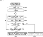
- FIG. 6 is a flowchart showing a detailed method of generating a control message using a weight by a communication module in a telematics device according to an embodiment of the present invention.
- the following description illustrates an example in which a communication module in a telematics device enters a reception standby state because the engine of the vehicle is stopped.
- count values of the amounts of the consumed current according to the operation time of the receiving unit 120 and the operation time of the transmitting unit 130 and a cumulative value thereof are initially set to 0 (S500 and S502).
- the control unit 140 of the communication module 100 summates a count value reflecting a first weight assigned to the operation time of the receiving unit 120 and a count value reflecting a second weight assigned to the operation time of the transmitting unit 130 (S504), and cumulatively calculates the summed count values (S506).
- the term “Rx on time” denotes the operation time of the receiving unit
- the term “Tx on time” denotes the operation time of the transmitting unit
- ⁇ denotes the first weight
- ⁇ denotes the second weight
- a and b are constants.
- ⁇ and ⁇ may be set to have a different value according to an electric field, an inter-band movement, a handover between heterogeneous networks, and a change in service status.
- the control unit 140 of the communication module 100 compares an elapsed time since the start of the reception standby state with a preset time (e.g., 96 hours) (S508), and when the elapsed time is less than the preset time, compares the cumulative value obtained in operation S506 with a predetermined value (S510).
- the control unit 140 generates a control message for turning off the communication module 100, setting a wake-up cycle to be longer, or limiting the use of a particular function of the communication module 100 when the cumulative value is larger than the predetermined value (S512).
- the control unit 140 repeats the operation S504 and the subsequent operations.
- control unit 140 may generate a control message for immediately turning off the communication module 100 (S514).
- Table 1 shows an example in which weights are set to have different values according to the electric field.
- Mode Cell power (dBm) Operation time of receiving unit Count value WCDMA Strong/intermediate electric field RSCP >-110 4 ⁇ 5ms 10 Weak electric field 1 RSCP -120 10 ⁇ 12ms 13 Weak electric field 2 RSCP ⁇ -120 45 ⁇ 51ms 35 LTE Strong/intermediate electric field RSRP >-132 5 ⁇ 10ms 13 Weak electric field RSRP ⁇ -133 16ms 20
- the count value reflecting a weight according to the electric field may be calculated as 10
- the count value reflecting a weight according to the electric field may be calculated as 13
- the count value reflecting a weight according to the electric field may be calculated as 35.
- the communication module 100 uses Long-Term Evolution (LTE), in the case when the operation time of the receiving unit in the strong/intermediate electric field is in a range of 5 to 10 ms, the count value reflecting a weight according to the electric field may be calculated as 13, and in the case when the operation time of the receiving unit in the weak electric field is 16 ms, the count value reflecting a weight according to the electric field may be calculated as 20.
- LTE Long-Term Evolution
- Table 1 illustrates an example in which the weights are set to vary according to only the electric field, the present invention is not limited thereto.
- the weights may be set to vary according to an inter-band movement, a handover between heterogeneous networks, and a change in service status.
- control unit 140 of the communication module 100 controls the communication module 100 by monitoring the amount of the current consumed by the telematics device 10 in the reception standby state, so that the battery unit 110 is prevented from being discharged without having to add an additional component.
- the present invention is not limited thereto.
- the communication module 100 may control the turn-off or the operation cycle of the communication module 100 by itself.
- telematics device 100 communication module 200: main controller 110: battery unit 120: receiving unit 130: transmitting unit 140: control unit 150: storage unit
Landscapes
- Engineering & Computer Science (AREA)
- Architecture (AREA)
- Computer Networks & Wireless Communication (AREA)
- Signal Processing (AREA)
- Mechanical Engineering (AREA)
- Civil Engineering (AREA)
- Structural Engineering (AREA)
- Mobile Radio Communication Systems (AREA)
- Telephone Function (AREA)
Abstract
Description
- The present invention relates to a telematics device, and more specifically, to a communication modem included in a telematics device.
- A telematics device mounted in a vehicle communicates with a remote telematics server. Using the communication allows a driver to remotely diagnose the vehicle, remotely control the vehicle, use traffic information received from the remote telematics server, or transmit a remote request to the telematics server.
- With developments in the telematics technology, there has been a recent global trend toward legalizing eCall that transmits relevant information through wireless communication for emergency services in a vehicle, and Era-glonass which is an emergency situation management system in a vehicle. Accordingly, mounting a telematics device in a vehicle is required.
- Meanwhile, when an engine of the vehicle is turned off, the telematics device enters a reception standby state. In this case, a remote user may control the vehicle or receive event information from the vehicle by using the telematics device in the vehicle. To this end, a communication modem included in the telematics device enters a reception standby mode in which the communication modem wakes up periodically.
- In general, the time for which the telematics device is kept in a reception standby state varies depending on the charge of a battery connected to the telematics device, and the maximum duration of the reception standby state is predetermined. However, in many cases, the battery connected to the telematics device may be discharged faster than a preset time due to an increase in power consumption caused by a weak electric field, an inter-band movement, a handover between heterogeneous networks, a change in service status, and the like.
- The present invention is directed to providing a communication modem included in a telematics device and a method of generating a control message therefor.
- One aspect of the present invention provides a communication module in a vehicle, including: a battery unit; a receiving unit set to receive power from the battery unit and operate on a predetermined cycle in a reception standby state; and a control unit set to cumulatively calculate an amount of a consumed current according to an operation time of the receiving unit, and when a value of the cumulative calculation exceeds a predetermined value, generate a control message for controlling an operation cycle of the receiving unit or controlling the communication module to be turned off.
- The communication module may further include a transmitting unit set to receive the power from the battery of the vehicle, and the control unit may be set to generate the control message by further cumulatively calculating an amount of a consumed current according to an operation time of the transmitting unit in the reception standby state.
- The control unit may be set to have the operation time of the receiving unit and the operation time of the transmitting unit assigned a first weight and a second weight that are different from each other, respectively.
- The control unit may be set to, when a cumulative value of a summation of an amount of the consumed power according to the operation time of the receiving unit reflecting the first weight and an amount of the consumed power according to the operation time of the transmitting unit reflecting the second weight exceeds a predetermined value, generate a control message for controlling the communication module to be turned off.
- Another aspect of the present invention provides a method of generating a control message for a communication module in a vehicle, the method including: cumulatively calculating an amount of a consumed current according to an operation time of a receiving unit that operates on a predetermined cycle in a reception standby state; comparing a value obtained in the cumulative calculation with a predetermined value; and when the value of the cumulative calculation exceeds the predetermined value, generating a control message for controlling an operation cycle of the receiving unit or controlling the communication module to be turned off.
- In the cumulative calculation, an operation time of a transmitting unit in the reception standby state may be further calculated in a cumulative manner.
- In the cumulative calculation, an amount of the consumed current according to the operation time of the receiving unit and an amount of a consumed current according to the operation time of the transmitting unit may be assigned a first weight and a second weight that are different from each other, respectively.
- In the generating of the control message, a control message for controlling the communication module to be turned off is generated when a cumulative value of a summation of the amount of the consumed current according to the operation time of the receiving unit reflecting the first weight and the amount of the consumed current according to the operation time of the transmitting unit reflecting the second weight exceeds a predetermined value.
- According to the embodiments of the present invention, it is possible to prevent the discharge of a battery connected to a telematics device in the reception standby state. Particularly, it is possible to prevent discharge of a battery connected to a telematics device even in an environment where power consumption is higher than normal due to due to a weak electric field, an inter-band movement, a handover between mobile networks, a change in service status, and the like.
-
-
FIG. 1 is a block diagram illustrating a telematics device according to an embodiment of the present invention. -
FIG. 2 is a block diagram illustrating a communication module (100) according to an embodiment of the present invention. -
FIG. 3 shows an example in which a receiving unit (120) periodically wakes up in a reception standby state. -
FIG. 4 is a flowchart showing a method of generating a control message of a communication module in a telematics device according to an embodiment of the present invention. -
FIG. 5 shows an example in which values of consumed currents according to an operation time of a receiving unit and an operation time of a transmitting unit in a reception standby state are cumulatively calculated. -
FIG. 6 is a flowchart showing a detailed method of generating a control message using a weight by a communication module in a telematics device according to an embodiment of the present invention - While the invention is susceptible to various modifications and alternative forms, specific embodiments thereof are shown by way of example in the drawings and will herein be described in detail. However, it should be understood that there is no intent to limit the invention to the specific embodiments, rather the invention is to cover all modifications, equivalents, and alternatives falling within the spirit and scope of the invention. It should be understood that, although the terms "first," "second," etc. may be used herein to describe various elements, these elements are not limited by these terms. These terms are only used to distinguish one element from another. For example, a first element could be termed a second element, and, similarly, a second element could also be termed a first element, without departing from the scope of the present invention. As used herein, the term "and/or" includes any one or combinations of the associated listed items.
- It should be understood that when an element is referred to as being "connected" or "coupled" to another element, the element can be directly connected or coupled to another element or intervening elements may be present. Conversely, when an element is referred to as being "directly connected" or "directly coupled" to another element, there are no intervening elements present. Other words used to describe a relationship between elements should be interpreted in a like fashion (i.e., "between" versus "directly between," "adjacent" versus "directly adjacent," etc.).
- The terminology used herein is for the purpose of describing particular embodiments only and is not intended to limit the invention. As used herein, the singular forms "a," "an," and "the" are intended to include the plural forms as well, unless the context clearly indicates otherwise. It should be further understood that the terms "comprises," "comprising," "includes," and/or "including," when used herein, specify the presence of stated features, integers, steps, operations, elements, components and/or groups thereof, and do not preclude the presence or addition of one or more other features, integers, steps, operations, elements, components, and/or groups thereof.
- Unless otherwise defined, all terms (including technical and scientific terms) used herein have the same meaning as commonly understood by one of ordinary skill in the art to which this invention belongs. It should be further understood that terms, such as those defined in commonly used dictionaries, should be interpreted as having a meaning that is consistent with their meaning in the context of the relevant art and are not to be interpreted in an idealized or overly formal sense unless expressly so defined herein.
- Hereinafter, embodiments of the present invention will be described with reference to the accompanying drawings in detail. For better understanding of the present invention, the same reference numerals are used to refer to the same elements through the description of the figures, and the description of the same elements will be omitted.
-
FIG. 1 is a block diagram illustrating a telematics device according to an embodiment of the present invention. - Referring to
FIG. 1 , atelematics device 10 includes acommunication module 100 and amain controller 200. Thecommunication module 100 remotely communicates with a telematics server. Accordingly, remote control, remote diagnosis, and the like may be performed. - The
main controller 200 is connected to thecommunication module 100 and performs overall control of thetelematics device 10. Themain controller 200 and thecommunication module 100 may be connected to each other in a wired or wireless manner. - Although not shown, the
telematics device 10 may further include a diagnosis manager for diagnosing a state of a vehicle, a storage unit for storing diagnostic information of the vehicle, and a display unit for displaying the diagnostic information of the vehicle. -
FIG. 2 is a block diagram illustrating thecommunication module 100 according to the embodiment of the present invention. - Referring to
FIG. 2 , thecommunication module 100 includes abattery unit 110, areceiving unit 120, a transmittingunit 130, acontrol unit 140, and astorage unit 150. - The
battery unit 110 stores electric power for being supplied to thecommunication module 100. Thebattery unit 110 may supply power to thecommunication module 100 when an engine of the vehicle is turned off or thecommunication module 100 may not receive power from the vehicle. - The receiving
unit 120 and the transmittingunit 130 receive signals from a base station (not shown) and transmit signals to the base station. Meanwhile, when the engine of the vehicle is turned off, thecommunication module 100 enters a reception standby state. In the reception standby state, thereceiving unit 120 receives power from thebattery unit 110 and periodically wakes up.FIG. 3 shows an example in which the receivingunit 120 periodically wakes up in a reception standby state. The receivingunit 120 may identify a paging signal from the base station through the periodic wake-up process. In addition, in the reception standby state, the transmittingunit 130 also receives the power from thebattery unit 110 and wakes up. In this case, the transmittingunit 130 may wake up periodically or when an event occurs. For example, in a reception standby state, the transmittingunit 130 may wake up when the receivingunit 120 receives a paging signal from the base station. As another example, in the reception standby state, the transmittingunit 130 may wake up when there is a signal to be transmitted by the transmitting unit. As another example, in the reception standby state, the transmittingunit 130 may be set to wake up together with the receivingunit 120. - In addition, the
control unit 140 performs overall control of thecommunication module 100. In particular, thecontrol unit 140 is set to, when thecommunication module 100 is in a reception standby state, cumulatively calculate the amounts of consumed currents according to an operation time of the receivingunit 120 and an operation time of the transmittingunit 130, and generate a control message for controlling an operation cycle of the receivingunit 120 or controlling thecommunication module 100 to be turned off in a case when a value of the cumulative calculation exceeds a predetermined value. - The
storage unit 150 stores all programs required for thecommunication module 100 to operate. In particular, thestorage unit 150 may be configured to store an operation cycle of the receivingunit 120 in a reception standby state, an amount of the consumed current according to the operation time of the receivingunit 120, and a program required for thecontrol unit 140 to cumulatively calculate the amounts of the consumed current according to the operation time of the receivingunit 120 and the amounts of the consumed current according to the operation time of the transmittingunit 130. -
FIG. 4 is a flowchart showing a method of generating a control message of a communication module in a telematics device according to an embodiment of the present invention. - Referring to 4, the
control unit 140 of thecommunication module 100 cumulatively calculates an amount of a consumed current according to an operation time of the receivingunit 120 and an amount of a consumed current according to an operation time of the transmittingunit 130 in a reception standby state (S400). Here, the amount of the consumed current according to the operation time of the receivingunit 120 may include an amount of a consumed current according to a time for which the receivingunit 120 periodically wakes up in a reception standby state as shown inFIG. 3 . The amount of the consumed current according to the operation time of the receivingunit 120 may further include an amount of a consumed current according to a time for which the receivingunit 120 performs an operation of receiving a signal while being kept in a wake-up state. The amount of the consumed current according to the operation time of the transmittingunit 130 may include an amount of a consumed current according to a time for which thetransmitting unit 130 periodically wakes up in a reception standby state. The amount of the consumed current according to the operation time of the transmittingunit 130 may further include an amount of a consumed current according to a time for which thetransmitting unit 130 performs an operation of transmitting a signal while being kept in a wake-up state.FIG. 5 shows an example in which the amounts of the consumed currents according to the operation time of the receivingunit 120 and the operation time of the transmittingunit 130 in the reception standby state are cumulatively calculated. Here, rx on and rx_off (time =) indicate the operation time of the receivingunit 120, lte_tx_on and lte_tx_off (time =) indicate the operation time of the transmittingunit 130, and cnt indicates a cumulative value obtained by sequentially accumulating the amount of the consumed current according to the operation time of the receivingunit 120, and the amount of the consumed current according to the operation time of the transmittingunit 130. - The
control unit 140 of thecommunication module 100 compares the cumulative value calculated in operation S400 with a predetermined value (S410), and when the cumulative value exceeds the predetermined value, generates a control message for controlling the operation cycle of the receivingunit 120 or controlling thecommunication module 100 to be turned off (S420). - For example, it is assumed that the
communication module 100 has specifications in which a reception standby state is maintained for 96 hours at an average of 2 mA. The total amount of a current allocated to thecommunication module 100 with the specifications is 2mA x 96h = 192mAh. Referring toFIG. 3 , when thecommunication module 100 operates normally in a reception standby state, and an amount of a current consumed in a single wake-up of the receivingunit 120 is 0.124 µAh, a maximum number of times of wake-ups of the receivingunit 120 is 192 mAh/0.124 µAh, that is, about 1,548,000 times, and when 96 hours have elapsed, thecommunication module 100 is turned off. However, when the operation time of the receivingunit 120 and the transmittingunit 130 is increased due to a weak electric field, an inter-band movement, a handover between mobile networks, a change in service status, and the like, thecontrol unit 140 may calculate a cumulative value of the amounts of the consumed current according to the operation time. When the cumulative value exceeds a predetermined value, thecontrol unit 140 may generate a control message even before 96 hours have elapsed since the start of the reception standby. Here, the control message may be a message for controlling the wake-up cycle of the receivingunit 120. For example, the control message may be a control message for lengthening the wake-up cycle of the receivingunit 120. Accordingly, the time for which thecommunication module 100 is kept in a reception standby state may be increased. As another example, the control message may be a control message for terminating thecommunication module 100 early before a preset amount of time (e.g., 96 hours) elapses. The control message generated by thecontrol unit 140 is transmitted to themain controller 200, and themain controller 200 changes the wake-up cycle of thecommunication module 100 or performs an early termination of thecommunication module 100 according to the control message. - Meanwhile, the amount of the current consumed during the operation time of the receiving
unit 120 and the amount of the current consumed during the operation time of the transmittingunit 130 may be different from each other. Accordingly, thecontrol unit 140 may assign different weights to the operation time of the receivingunit 120 and the operation time of the transmittingunit 130 to calculate a cumulative value. -
FIG. 6 is a flowchart showing a detailed method of generating a control message using a weight by a communication module in a telematics device according to an embodiment of the present invention. The following description illustrates an example in which a communication module in a telematics device enters a reception standby state because the engine of the vehicle is stopped. - Referring to
FIG. 6 , count values of the amounts of the consumed current according to the operation time of the receivingunit 120 and the operation time of the transmittingunit 130 and a cumulative value thereof are initially set to 0 (S500 and S502). - In a reception standby state, the
control unit 140 of thecommunication module 100 summates a count value reflecting a first weight assigned to the operation time of the receivingunit 120 and a count value reflecting a second weight assigned to the operation time of the transmitting unit 130 (S504), and cumulatively calculates the summed count values (S506). Here, the term "Rx on time" denotes the operation time of the receiving unit, the term "Tx on time" denotes the operation time of the transmitting unit, α denotes the first weight, β denotes the second weight, and a and b are constants. α and β may be set to have a different value according to an electric field, an inter-band movement, a handover between heterogeneous networks, and a change in service status. - The
control unit 140 of thecommunication module 100 compares an elapsed time since the start of the reception standby state with a preset time (e.g., 96 hours) (S508), and when the elapsed time is less than the preset time, compares the cumulative value obtained in operation S506 with a predetermined value (S510). Thecontrol unit 140 generates a control message for turning off thecommunication module 100, setting a wake-up cycle to be longer, or limiting the use of a particular function of thecommunication module 100 when the cumulative value is larger than the predetermined value (S512). On the other hand, when the cumulative value is not larger than the predetermined value, thecontrol unit 140 repeats the operation S504 and the subsequent operations. - On the other hand, when it is determined in operation S508 that the elapsed time since the start of the reception standby state exceeds the preset time (e.g., 96 hours), the
control unit 140 may generate a control message for immediately turning off the communication module 100 (S514). - Table 1 shows an example in which weights are set to have different values according to the electric field.
[Table 1] Mode Cell power (dBm) Operation time of receiving unit Count value WCDMA Strong/intermediate electric field RSCP >-110 4∼ 5ms 10 Weak electric field 1 RSCP =-120 10∼12ms 13 Weak electric field 2 RSCP <-120 45∼51ms 35 LTE Strong/intermediate electric field RSRP >-132 5∼10ms 13 Weak electric field RSRP <-133 16ms 20 - Referring to Table 1, when the
communication module 100 uses wideband code division multiple access (WCDMA), in the case when the operation time of the receiving unit in the strong/intermediate electric field is in a range of 4 to 5 ms, the count value reflecting a weight according to the electric field may be calculated as 10, in the case when the operation time of the receiving unit in the weak electric field 1 is in a range of 10 to 12 ms, the count value reflecting a weight according to the electric field may be calculated as 13, and in the case when the operation time of the receiving unit in the weak electric field 2 is in a range of 45 to 51 ms, the count value reflecting a weight according to the electric field may be calculated as 35. - Similarly, when the
communication module 100 uses Long-Term Evolution (LTE), in the case when the operation time of the receiving unit in the strong/intermediate electric field is in a range of 5 to 10 ms, the count value reflecting a weight according to the electric field may be calculated as 13, and in the case when the operation time of the receiving unit in the weak electric field is 16 ms, the count value reflecting a weight according to the electric field may be calculated as 20. In addition, an equation may be used rather than using the weight value table as shown in Table 1. - Although Table 1 illustrates an example in which the weights are set to vary according to only the electric field, the present invention is not limited thereto. For example, the weights may be set to vary according to an inter-band movement, a handover between heterogeneous networks, and a change in service status.
- As described above, according to the embodiment of the present invention, the
control unit 140 of thecommunication module 100 controls thecommunication module 100 by monitoring the amount of the current consumed by thetelematics device 10 in the reception standby state, so that thebattery unit 110 is prevented from being discharged without having to add an additional component. - Although the above description is made in relation to the
communication module 100 that generates a control message and transmits the generated control message to themain controller 200, the present invention is not limited thereto. For example, thecommunication module 100 may control the turn-off or the operation cycle of thecommunication module 100 by itself. - Although the present invention has been described with reference to the exemplary embodiments, it should be understood by those of skilled in the art that changes and modifications are possible without departing from the scope and sprit of the disclosure.
-
10: telematics device 100: communication module 200: main controller 110: battery unit 120: receiving unit 130: transmitting unit 140: control unit 150: storage unit
Claims (19)
- A communication module in a vehicle, comprising:a receiving unit set to receive power from a battery of the vehicle and operate on a predetermined cycle in a reception standby state; anda control unit set to accumulate a count value according to an operation time of the receiving unit, and when a result of the accumulated count values exceeds a predetermined value, control an operation cycle of the receiving unit or terminate operation of the communication module.
- The communication module of claim 1, wherein the count value according to the operation time of the receiving unit includes a count value corresponding to an amount of consumed current according to the operation time of the receiving unit.
- The communication module of claim 1, wherein the count value according to the operation time of the receiving unit includes a count value reflecting a first weight assigned to the operation time of the receiving unit.
- The communication module of claim 3, wherein the first weight is set to vary according to at least one of an electric field, an inter-band movement, a handover between heterogeneous networks, and a change in service status.
- The communication module of claim 1, wherein the predetermined value is a maximum operation count value corresponding to a current amount allocated to the communication module.
- The communication module of claim 1, wherein the control unit generates a control message for controlling the communication module to be turned off so as to terminate the operation of the communication module.
- The communication module of claim 6, wherein the control message includes a control message for early termination of the communication module before a preset reception standby time.
- A communication module in a vehicle, comprising:a receiving unit set to receive power from a battery of the vehicle, and operate on a predetermined cycle in a reception standby state;a transmitting unit set to receive the power from the battery of the vehicle; anda control unit set to accumulate a count value according to an operation time of the receiving unit and a count value according to an operation time of the transmitting unit, and when a result of the accumulated count values exceeds a predetermined value, control at least one of an operation cycle of the receiving unit and an operation cycle of the transmitting unit or terminate operation of the communication module.
- The communication module of claim 8, wherein the count value according to the operation time of the receiving unit includes a count value corresponding to an amount of consumed current according to the operation time of the receiving unit, and
the count value according to the operation time of the transmitting unit includes a count value corresponding to an amount of consumed current according to the operation time of the transmitting unit. - The communication module of claim 8, wherein the count value according to the operation time of the receiving unit includes a count value reflecting a first weight assigned to the operation time of the receiving unit, and
the count value according to the operation time of the transmitting unit includes a count value reflecting a second weight assigned to the operation time of the transmitting unit,
wherein the first weight is different from the second weight. - The communication module of claim 10, wherein the control unit is set to accumulate the count value reflecting the first weight assigned to the operation time of the receiving unit, and the count value reflecting the second weight assigned to the operation time of the transmitting unit, and when a result of the accumulated count values exceeds a predetermined value, control at least one of the operation cycle of the receiving unit and the operation cycle of the transmitting unit or terminate the operation of the communication module.
- A method of generating a control message for a communication module in a vehicle, the method comprising:calculating an operation time of a receiving unit that operates on a predetermined cycle in a reception standby state;accumulating count values according to the operation time of the receiving unit;comparing a result of the accumulated count values with a predetermined value; andwhen the result of the accumulated count values exceeds the predetermined value, generating a control message for controlling an operation cycle of the receiving unit or controlling the communication module to be turned off.
- The method of claim 12, wherein the count value according to the operation time of the receiving unit includes a count value reflecting a first weight assigned to the operation time of the receiving unit.
- The method of claim 13, wherein the first weight is set to vary according to at least one of an electric field, an inter-band movement, a handover between heterogeneous networks, and a change in service status.
- The method of claim 12, wherein the predetermined value is a maximum operation count value corresponding to a current amount allocated to the communication module.
- The method of claim 12, wherein the accumulating according to the operation time of the receiving unit further comprises accumulating a count value according to an operation time of a transmitting unit in a reception standby state.
- The method of claim 15, wherein the count value according to the operation time of the transmitting unit includes a count value reflecting a second weight assigned to the operation time of the transmitting unit.
- The method of claim 17, wherein the first weight is different from the second weight.
- The method of claim 12, further comprising:triggering a reception standby timer when the communication module enters a reception standby state; andgenerating a control message for controlling the communication module to be turned off when the reception standby timer expires.
Applications Claiming Priority (2)
| Application Number | Priority Date | Filing Date | Title |
|---|---|---|---|
| KR1020160007087A KR101856125B1 (en) | 2016-01-20 | 2016-01-20 | Communication module in vehicle and method of generating control message of the same |
| PCT/KR2016/014539 WO2017126807A1 (en) | 2016-01-20 | 2016-12-12 | Communication module in vehicle and control message generating method therefor |
Publications (3)
| Publication Number | Publication Date |
|---|---|
| EP3407648A1 true EP3407648A1 (en) | 2018-11-28 |
| EP3407648A4 EP3407648A4 (en) | 2019-07-24 |
| EP3407648B1 EP3407648B1 (en) | 2021-04-14 |
Family
ID=59362751
Family Applications (1)
| Application Number | Title | Priority Date | Filing Date |
|---|---|---|---|
| EP16886650.7A Active EP3407648B1 (en) | 2016-01-20 | 2016-12-12 | Communication module in vehicle and control message generating method therefor |
Country Status (5)
| Country | Link |
|---|---|
| US (1) | US11343765B2 (en) |
| EP (1) | EP3407648B1 (en) |
| KR (1) | KR101856125B1 (en) |
| CN (1) | CN108496394B (en) |
| WO (1) | WO2017126807A1 (en) |
Family Cites Families (17)
| Publication number | Priority date | Publication date | Assignee | Title |
|---|---|---|---|---|
| SE514232C2 (en) * | 1999-01-27 | 2001-01-29 | Ericsson Telefon Ab L M | Portable multi-band communication device and a method for determining a charge consumption for the same |
| US6480472B1 (en) * | 1999-07-21 | 2002-11-12 | Qualcomm Incorporated | Mobile station supervision of the forward dedicated control channel when in the discontinuous transmission mode |
| SE519001C2 (en) * | 2000-08-29 | 2002-12-17 | Volvo Teknisk Utveckling Ab | Method and objects for energy-saving operation of a communication system |
| US7369849B2 (en) * | 2002-08-06 | 2008-05-06 | General Motors Corporation | Method and system for registering an in-vehicle cellular phone |
| US7596366B2 (en) * | 2002-12-31 | 2009-09-29 | Temic Automotive Of North America, Inc. | System and method for controlling the power in a wireless client device |
| US7610035B2 (en) * | 2002-12-31 | 2009-10-27 | Temic Automotive Of North America, Inc. | System and method for controlling the power in a wireless client device |
| KR100597519B1 (en) | 2004-12-07 | 2006-07-10 | 한국전자통신연구원 | Apparatus and method for telematics wake-up system |
| KR100738130B1 (en) | 2005-07-07 | 2007-07-10 | 현대자동차주식회사 | Power control method of telematics terminal |
| US7714707B2 (en) * | 2007-05-18 | 2010-05-11 | Trw Automotive U.S. Llc | System for measuring life expectancy of a tire condition monitoring system |
| US8000842B2 (en) * | 2007-09-28 | 2011-08-16 | General Motors Llc | Method to prevent excessive current drain of telematics unit network access device |
| US8670897B1 (en) * | 2009-12-02 | 2014-03-11 | Feeney Wireless, LLC | Mobile in-vehicle communication and routing apparatus, system, and method |
| KR20130002661A (en) | 2011-06-29 | 2013-01-08 | 현대모비스 주식회사 | System for checking state of automobile and control method thereof |
| JP5967516B2 (en) * | 2011-11-22 | 2016-08-10 | パナソニックIpマネジメント株式会社 | Power management apparatus, power management program, and power distribution system |
| US20130158860A1 (en) * | 2011-12-14 | 2013-06-20 | Qualcomm Incorporated | Location and event triggered navigation dormancy and wakeup |
| JP2014069592A (en) * | 2012-09-27 | 2014-04-21 | Mitsubishi Motors Corp | Remote control system for on-vehicle equipment |
| US8655307B1 (en) * | 2012-10-26 | 2014-02-18 | Lookout, Inc. | System and method for developing, updating, and using user device behavioral context models to modify user, device, and application state, settings and behavior for enhanced user security |
| KR102113771B1 (en) | 2013-10-16 | 2020-05-21 | 현대모비스 주식회사 | Apparatus and method for judging of current consumption of battery |
-
2016
- 2016-01-20 KR KR1020160007087A patent/KR101856125B1/en active Active
- 2016-12-12 EP EP16886650.7A patent/EP3407648B1/en active Active
- 2016-12-12 WO PCT/KR2016/014539 patent/WO2017126807A1/en not_active Ceased
- 2016-12-12 US US16/071,409 patent/US11343765B2/en active Active
- 2016-12-12 CN CN201680079518.6A patent/CN108496394B/en active Active
Also Published As
| Publication number | Publication date |
|---|---|
| EP3407648B1 (en) | 2021-04-14 |
| EP3407648A4 (en) | 2019-07-24 |
| CN108496394A (en) | 2018-09-04 |
| US20210204210A1 (en) | 2021-07-01 |
| CN108496394B (en) | 2021-07-09 |
| KR20170087293A (en) | 2017-07-28 |
| US11343765B2 (en) | 2022-05-24 |
| WO2017126807A1 (en) | 2017-07-27 |
| KR101856125B1 (en) | 2018-05-09 |
Similar Documents
| Publication | Publication Date | Title |
|---|---|---|
| EP1435709B1 (en) | System and method for controlling the power in a wireless client device | |
| US7610035B2 (en) | System and method for controlling the power in a wireless client device | |
| US8649816B2 (en) | Wireless communication system and method of operating the same for low power consumption of terminal device | |
| EP2036221B1 (en) | Adaptive drx cycle length based on available battery power | |
| EP2286630B1 (en) | System and method for heartbeat signal generation | |
| US7496060B2 (en) | Extending battery life in communication devices having a plurality of receivers | |
| KR101553596B1 (en) | Application processor wake-up suppression | |
| EP2929732B1 (en) | Intelligent m2m energy optimization algorithm | |
| KR101569299B1 (en) | Pulse frequency modulation (pfm) mode lock out for regulators when receive signal quality is low | |
| US9078212B2 (en) | System and method for reducing power used for radio transmission and reception | |
| EP1966914B1 (en) | Radio station and method of operating a radio station. | |
| US9094916B1 (en) | System and method for adjusting power used in reception in a wireless packet network | |
| US7986652B1 (en) | System and method for adjusting power used in transmission in a wireless packet network | |
| WO2010019400A1 (en) | Method and apparatus for adjusting an on duration in a discontinuous receive transmission mode | |
| EP3407648B1 (en) | Communication module in vehicle and control message generating method therefor | |
| CN111711980B (en) | Method for reducing power consumption of drive test terminal | |
| KR20190080391A (en) | Method for controlling state transition of terminal and estimating load of mobile network using inactive state, and apparatus for mobile communication applying same | |
| CN111800847B (en) | Equipment control method and device | |
| US12250635B2 (en) | Method for power efficient data transmission | |
| KR20080046837A (en) | Power saving method and device in communication system | |
| KR102633956B1 (en) | communication module of wireless communication terminal and method of generating control message thereof | |
| EP2247036B1 (en) | System and method for controlling the power in a wireless client device | |
| JP2018056641A (en) | Communication device and control method of communication device |
Legal Events
| Date | Code | Title | Description |
|---|---|---|---|
| STAA | Information on the status of an ep patent application or granted ep patent |
Free format text: STATUS: THE INTERNATIONAL PUBLICATION HAS BEEN MADE |
|
| PUAI | Public reference made under article 153(3) epc to a published international application that has entered the european phase |
Free format text: ORIGINAL CODE: 0009012 |
|
| STAA | Information on the status of an ep patent application or granted ep patent |
Free format text: STATUS: REQUEST FOR EXAMINATION WAS MADE |
|
| 17P | Request for examination filed |
Effective date: 20180720 |
|
| AK | Designated contracting states |
Kind code of ref document: A1 Designated state(s): AL AT BE BG CH CY CZ DE DK EE ES FI FR GB GR HR HU IE IS IT LI LT LU LV MC MK MT NL NO PL PT RO RS SE SI SK SM TR |
|
| AX | Request for extension of the european patent |
Extension state: BA ME |
|
| DAV | Request for validation of the european patent (deleted) | ||
| DAX | Request for extension of the european patent (deleted) | ||
| A4 | Supplementary search report drawn up and despatched |
Effective date: 20190626 |
|
| RIC1 | Information provided on ipc code assigned before grant |
Ipc: H04W 52/02 20090101AFI20190620BHEP |
|
| GRAP | Despatch of communication of intention to grant a patent |
Free format text: ORIGINAL CODE: EPIDOSNIGR1 |
|
| STAA | Information on the status of an ep patent application or granted ep patent |
Free format text: STATUS: GRANT OF PATENT IS INTENDED |
|
| INTG | Intention to grant announced |
Effective date: 20201026 |
|
| GRAS | Grant fee paid |
Free format text: ORIGINAL CODE: EPIDOSNIGR3 |
|
| GRAA | (expected) grant |
Free format text: ORIGINAL CODE: 0009210 |
|
| STAA | Information on the status of an ep patent application or granted ep patent |
Free format text: STATUS: THE PATENT HAS BEEN GRANTED |
|
| AK | Designated contracting states |
Kind code of ref document: B1 Designated state(s): AL AT BE BG CH CY CZ DE DK EE ES FI FR GB GR HR HU IE IS IT LI LT LU LV MC MK MT NL NO PL PT RO RS SE SI SK SM TR |
|
| REG | Reference to a national code |
Ref country code: GB Ref legal event code: FG4D |
|
| REG | Reference to a national code |
Ref country code: CH Ref legal event code: EP |
|
| REG | Reference to a national code |
Ref country code: DE Ref legal event code: R096 Ref document number: 602016056284 Country of ref document: DE |
|
| REG | Reference to a national code |
Ref country code: IE Ref legal event code: FG4D |
|
| REG | Reference to a national code |
Ref country code: AT Ref legal event code: REF Ref document number: 1383579 Country of ref document: AT Kind code of ref document: T Effective date: 20210515 |
|
| REG | Reference to a national code |
Ref country code: NL Ref legal event code: FP |
|
| REG | Reference to a national code |
Ref country code: LT Ref legal event code: MG9D |
|
| REG | Reference to a national code |
Ref country code: AT Ref legal event code: MK05 Ref document number: 1383579 Country of ref document: AT Kind code of ref document: T Effective date: 20210414 |
|
| PG25 | Lapsed in a contracting state [announced via postgrant information from national office to epo] |
Ref country code: LT Free format text: LAPSE BECAUSE OF FAILURE TO SUBMIT A TRANSLATION OF THE DESCRIPTION OR TO PAY THE FEE WITHIN THE PRESCRIBED TIME-LIMIT Effective date: 20210414 Ref country code: FI Free format text: LAPSE BECAUSE OF FAILURE TO SUBMIT A TRANSLATION OF THE DESCRIPTION OR TO PAY THE FEE WITHIN THE PRESCRIBED TIME-LIMIT Effective date: 20210414 Ref country code: AT Free format text: LAPSE BECAUSE OF FAILURE TO SUBMIT A TRANSLATION OF THE DESCRIPTION OR TO PAY THE FEE WITHIN THE PRESCRIBED TIME-LIMIT Effective date: 20210414 Ref country code: BG Free format text: LAPSE BECAUSE OF FAILURE TO SUBMIT A TRANSLATION OF THE DESCRIPTION OR TO PAY THE FEE WITHIN THE PRESCRIBED TIME-LIMIT Effective date: 20210714 Ref country code: HR Free format text: LAPSE BECAUSE OF FAILURE TO SUBMIT A TRANSLATION OF THE DESCRIPTION OR TO PAY THE FEE WITHIN THE PRESCRIBED TIME-LIMIT Effective date: 20210414 |
|
| PG25 | Lapsed in a contracting state [announced via postgrant information from national office to epo] |
Ref country code: LV Free format text: LAPSE BECAUSE OF FAILURE TO SUBMIT A TRANSLATION OF THE DESCRIPTION OR TO PAY THE FEE WITHIN THE PRESCRIBED TIME-LIMIT Effective date: 20210414 Ref country code: IS Free format text: LAPSE BECAUSE OF FAILURE TO SUBMIT A TRANSLATION OF THE DESCRIPTION OR TO PAY THE FEE WITHIN THE PRESCRIBED TIME-LIMIT Effective date: 20210814 Ref country code: GR Free format text: LAPSE BECAUSE OF FAILURE TO SUBMIT A TRANSLATION OF THE DESCRIPTION OR TO PAY THE FEE WITHIN THE PRESCRIBED TIME-LIMIT Effective date: 20210715 Ref country code: NO Free format text: LAPSE BECAUSE OF FAILURE TO SUBMIT A TRANSLATION OF THE DESCRIPTION OR TO PAY THE FEE WITHIN THE PRESCRIBED TIME-LIMIT Effective date: 20210714 Ref country code: PL Free format text: LAPSE BECAUSE OF FAILURE TO SUBMIT A TRANSLATION OF THE DESCRIPTION OR TO PAY THE FEE WITHIN THE PRESCRIBED TIME-LIMIT Effective date: 20210414 Ref country code: PT Free format text: LAPSE BECAUSE OF FAILURE TO SUBMIT A TRANSLATION OF THE DESCRIPTION OR TO PAY THE FEE WITHIN THE PRESCRIBED TIME-LIMIT Effective date: 20210816 Ref country code: SE Free format text: LAPSE BECAUSE OF FAILURE TO SUBMIT A TRANSLATION OF THE DESCRIPTION OR TO PAY THE FEE WITHIN THE PRESCRIBED TIME-LIMIT Effective date: 20210414 Ref country code: RS Free format text: LAPSE BECAUSE OF FAILURE TO SUBMIT A TRANSLATION OF THE DESCRIPTION OR TO PAY THE FEE WITHIN THE PRESCRIBED TIME-LIMIT Effective date: 20210414 |
|
| REG | Reference to a national code |
Ref country code: DE Ref legal event code: R097 Ref document number: 602016056284 Country of ref document: DE |
|
| PG25 | Lapsed in a contracting state [announced via postgrant information from national office to epo] |
Ref country code: ES Free format text: LAPSE BECAUSE OF FAILURE TO SUBMIT A TRANSLATION OF THE DESCRIPTION OR TO PAY THE FEE WITHIN THE PRESCRIBED TIME-LIMIT Effective date: 20210414 Ref country code: RO Free format text: LAPSE BECAUSE OF FAILURE TO SUBMIT A TRANSLATION OF THE DESCRIPTION OR TO PAY THE FEE WITHIN THE PRESCRIBED TIME-LIMIT Effective date: 20210414 Ref country code: CZ Free format text: LAPSE BECAUSE OF FAILURE TO SUBMIT A TRANSLATION OF THE DESCRIPTION OR TO PAY THE FEE WITHIN THE PRESCRIBED TIME-LIMIT Effective date: 20210414 Ref country code: DK Free format text: LAPSE BECAUSE OF FAILURE TO SUBMIT A TRANSLATION OF THE DESCRIPTION OR TO PAY THE FEE WITHIN THE PRESCRIBED TIME-LIMIT Effective date: 20210414 Ref country code: EE Free format text: LAPSE BECAUSE OF FAILURE TO SUBMIT A TRANSLATION OF THE DESCRIPTION OR TO PAY THE FEE WITHIN THE PRESCRIBED TIME-LIMIT Effective date: 20210414 Ref country code: SK Free format text: LAPSE BECAUSE OF FAILURE TO SUBMIT A TRANSLATION OF THE DESCRIPTION OR TO PAY THE FEE WITHIN THE PRESCRIBED TIME-LIMIT Effective date: 20210414 Ref country code: SM Free format text: LAPSE BECAUSE OF FAILURE TO SUBMIT A TRANSLATION OF THE DESCRIPTION OR TO PAY THE FEE WITHIN THE PRESCRIBED TIME-LIMIT Effective date: 20210414 |
|
| PLBE | No opposition filed within time limit |
Free format text: ORIGINAL CODE: 0009261 |
|
| STAA | Information on the status of an ep patent application or granted ep patent |
Free format text: STATUS: NO OPPOSITION FILED WITHIN TIME LIMIT |
|
| 26N | No opposition filed |
Effective date: 20220117 |
|
| PG25 | Lapsed in a contracting state [announced via postgrant information from national office to epo] |
Ref country code: IS Free format text: LAPSE BECAUSE OF FAILURE TO SUBMIT A TRANSLATION OF THE DESCRIPTION OR TO PAY THE FEE WITHIN THE PRESCRIBED TIME-LIMIT Effective date: 20210814 Ref country code: AL Free format text: LAPSE BECAUSE OF FAILURE TO SUBMIT A TRANSLATION OF THE DESCRIPTION OR TO PAY THE FEE WITHIN THE PRESCRIBED TIME-LIMIT Effective date: 20210414 |
|
| PG25 | Lapsed in a contracting state [announced via postgrant information from national office to epo] |
Ref country code: MC Free format text: LAPSE BECAUSE OF FAILURE TO SUBMIT A TRANSLATION OF THE DESCRIPTION OR TO PAY THE FEE WITHIN THE PRESCRIBED TIME-LIMIT Effective date: 20210414 Ref country code: IT Free format text: LAPSE BECAUSE OF FAILURE TO SUBMIT A TRANSLATION OF THE DESCRIPTION OR TO PAY THE FEE WITHIN THE PRESCRIBED TIME-LIMIT Effective date: 20210414 |
|
| REG | Reference to a national code |
Ref country code: CH Ref legal event code: PL |
|
| REG | Reference to a national code |
Ref country code: BE Ref legal event code: MM Effective date: 20211231 |
|
| PG25 | Lapsed in a contracting state [announced via postgrant information from national office to epo] |
Ref country code: LU Free format text: LAPSE BECAUSE OF NON-PAYMENT OF DUE FEES Effective date: 20211212 Ref country code: IE Free format text: LAPSE BECAUSE OF NON-PAYMENT OF DUE FEES Effective date: 20211212 |
|
| PG25 | Lapsed in a contracting state [announced via postgrant information from national office to epo] |
Ref country code: FR Free format text: LAPSE BECAUSE OF NON-PAYMENT OF DUE FEES Effective date: 20211231 Ref country code: BE Free format text: LAPSE BECAUSE OF NON-PAYMENT OF DUE FEES Effective date: 20211231 |
|
| PG25 | Lapsed in a contracting state [announced via postgrant information from national office to epo] |
Ref country code: LI Free format text: LAPSE BECAUSE OF NON-PAYMENT OF DUE FEES Effective date: 20211231 Ref country code: CH Free format text: LAPSE BECAUSE OF NON-PAYMENT OF DUE FEES Effective date: 20211231 |
|
| PG25 | Lapsed in a contracting state [announced via postgrant information from national office to epo] |
Ref country code: CY Free format text: LAPSE BECAUSE OF FAILURE TO SUBMIT A TRANSLATION OF THE DESCRIPTION OR TO PAY THE FEE WITHIN THE PRESCRIBED TIME-LIMIT Effective date: 20210414 |
|
| PG25 | Lapsed in a contracting state [announced via postgrant information from national office to epo] |
Ref country code: HU Free format text: LAPSE BECAUSE OF FAILURE TO SUBMIT A TRANSLATION OF THE DESCRIPTION OR TO PAY THE FEE WITHIN THE PRESCRIBED TIME-LIMIT; INVALID AB INITIO Effective date: 20161212 |
|
| PG25 | Lapsed in a contracting state [announced via postgrant information from national office to epo] |
Ref country code: MK Free format text: LAPSE BECAUSE OF FAILURE TO SUBMIT A TRANSLATION OF THE DESCRIPTION OR TO PAY THE FEE WITHIN THE PRESCRIBED TIME-LIMIT Effective date: 20210414 |
|
| PG25 | Lapsed in a contracting state [announced via postgrant information from national office to epo] |
Ref country code: MT Free format text: LAPSE BECAUSE OF FAILURE TO SUBMIT A TRANSLATION OF THE DESCRIPTION OR TO PAY THE FEE WITHIN THE PRESCRIBED TIME-LIMIT Effective date: 20210414 |
|
| PG25 | Lapsed in a contracting state [announced via postgrant information from national office to epo] |
Ref country code: TR Free format text: LAPSE BECAUSE OF FAILURE TO SUBMIT A TRANSLATION OF THE DESCRIPTION OR TO PAY THE FEE WITHIN THE PRESCRIBED TIME-LIMIT Effective date: 20210414 |
|
| PGFP | Annual fee paid to national office [announced via postgrant information from national office to epo] |
Ref country code: NL Payment date: 20251120 Year of fee payment: 10 |
|
| PGFP | Annual fee paid to national office [announced via postgrant information from national office to epo] |
Ref country code: DE Payment date: 20251120 Year of fee payment: 10 |
|
| PGFP | Annual fee paid to national office [announced via postgrant information from national office to epo] |
Ref country code: GB Payment date: 20251120 Year of fee payment: 10 |