EP3407507A1 - Signal transmission method of wireless communication system, base station and user equipment - Google Patents
Signal transmission method of wireless communication system, base station and user equipment Download PDFInfo
- Publication number
- EP3407507A1 EP3407507A1 EP17741025.5A EP17741025A EP3407507A1 EP 3407507 A1 EP3407507 A1 EP 3407507A1 EP 17741025 A EP17741025 A EP 17741025A EP 3407507 A1 EP3407507 A1 EP 3407507A1
- Authority
- EP
- European Patent Office
- Prior art keywords
- user data
- phase
- layer
- reference signal
- compensation value
- Prior art date
- Legal status (The legal status is an assumption and is not a legal conclusion. Google has not performed a legal analysis and makes no representation as to the accuracy of the status listed.)
- Granted
Links
Images




Classifications
-
- H—ELECTRICITY
- H04—ELECTRIC COMMUNICATION TECHNIQUE
- H04L—TRANSMISSION OF DIGITAL INFORMATION, e.g. TELEGRAPHIC COMMUNICATION
- H04L25/00—Baseband systems
- H04L25/38—Synchronous or start-stop systems, e.g. for Baudot code
- H04L25/40—Transmitting circuits; Receiving circuits
- H04L25/49—Transmitting circuits; Receiving circuits using code conversion at the transmitter; using predistortion; using insertion of idle bits for obtaining a desired frequency spectrum; using three or more amplitude levels ; Baseband coding techniques specific to data transmission systems
- H04L25/497—Transmitting circuits; Receiving circuits using code conversion at the transmitter; using predistortion; using insertion of idle bits for obtaining a desired frequency spectrum; using three or more amplitude levels ; Baseband coding techniques specific to data transmission systems by correlative coding, e.g. partial response coding or echo modulation coding transmitters and receivers for partial response systems
- H04L25/4975—Correlative coding using Tomlinson precoding, Harashima precoding, Trellis precoding or GPRS
-
- H—ELECTRICITY
- H04—ELECTRIC COMMUNICATION TECHNIQUE
- H04B—TRANSMISSION
- H04B1/00—Details of transmission systems, not covered by a single one of groups H04B3/00 - H04B13/00; Details of transmission systems not characterised by the medium used for transmission
- H04B1/69—Spread spectrum techniques
- H04B1/707—Spread spectrum techniques using direct sequence modulation
- H04B1/7097—Interference-related aspects
- H04B1/7103—Interference-related aspects the interference being multiple access interference
- H04B1/7107—Subtractive interference cancellation
-
- H—ELECTRICITY
- H04—ELECTRIC COMMUNICATION TECHNIQUE
- H04B—TRANSMISSION
- H04B17/00—Monitoring; Testing
- H04B17/30—Monitoring; Testing of propagation channels
- H04B17/309—Measuring or estimating channel quality parameters
- H04B17/318—Received signal strength
- H04B17/328—Reference signal received power [RSRP]; Reference signal received quality [RSRQ]
-
- H—ELECTRICITY
- H04—ELECTRIC COMMUNICATION TECHNIQUE
- H04B—TRANSMISSION
- H04B7/00—Radio transmission systems, i.e. using radiation field
- H04B7/02—Diversity systems; Multi-antenna system, i.e. transmission or reception using multiple antennas
- H04B7/04—Diversity systems; Multi-antenna system, i.e. transmission or reception using multiple antennas using two or more spaced independent antennas
- H04B7/0413—MIMO systems
- H04B7/0456—Selection of precoding matrices or codebooks, e.g. using matrices antenna weighting
-
- H—ELECTRICITY
- H04—ELECTRIC COMMUNICATION TECHNIQUE
- H04B—TRANSMISSION
- H04B7/00—Radio transmission systems, i.e. using radiation field
- H04B7/02—Diversity systems; Multi-antenna system, i.e. transmission or reception using multiple antennas
- H04B7/04—Diversity systems; Multi-antenna system, i.e. transmission or reception using multiple antennas using two or more spaced independent antennas
- H04B7/06—Diversity systems; Multi-antenna system, i.e. transmission or reception using multiple antennas using two or more spaced independent antennas at the transmitting station
-
- H—ELECTRICITY
- H04—ELECTRIC COMMUNICATION TECHNIQUE
- H04L—TRANSMISSION OF DIGITAL INFORMATION, e.g. TELEGRAPHIC COMMUNICATION
- H04L5/00—Arrangements affording multiple use of the transmission path
- H04L5/003—Arrangements for allocating sub-channels of the transmission path
- H04L5/0048—Allocation of pilot signals, i.e. of signals known to the receiver
-
- H—ELECTRICITY
- H04—ELECTRIC COMMUNICATION TECHNIQUE
- H04B—TRANSMISSION
- H04B1/00—Details of transmission systems, not covered by a single one of groups H04B3/00 - H04B13/00; Details of transmission systems not characterised by the medium used for transmission
- H04B1/69—Spread spectrum techniques
- H04B1/707—Spread spectrum techniques using direct sequence modulation
- H04B1/7097—Interference-related aspects
- H04B1/7103—Interference-related aspects the interference being multiple access interference
- H04B1/7107—Subtractive interference cancellation
- H04B2001/71077—Partial interference cancellation
-
- H—ELECTRICITY
- H04—ELECTRIC COMMUNICATION TECHNIQUE
- H04B—TRANSMISSION
- H04B7/00—Radio transmission systems, i.e. using radiation field
- H04B7/02—Diversity systems; Multi-antenna system, i.e. transmission or reception using multiple antennas
- H04B7/04—Diversity systems; Multi-antenna system, i.e. transmission or reception using multiple antennas using two or more spaced independent antennas
- H04B7/0413—MIMO systems
- H04B7/0452—Multi-user MIMO systems
Definitions
- the present application relates to communication technology, and particularly to a signal transmission method of a wireless communication system, base station, user equipment.
- a wireless communication system made up of a transmitting end, a receiving end and a wireless channel, transmits various signals using electromagnetic waves.
- wireless communication systems have gradually evolved from the first, second, third, and fourth generations to the fifth generation (5G), and more types of wireless communication systems may emerge in the future.
- 5G fifth generation
- wireless communication systems are becoming more and more competent in supporting -multi-user transmissions.
- interference between different users also appears.
- the system is time division, frequency division, space division or code division
- the presence of multi-layer user data results in interference between user data of different layers, and the interference may affect the restoration of signals at the receiving end. Therefore, there is increasing need for interference cancellation in wireless communication systems.
- Embodiments of the present application provide a signal transmission method of a wireless communication system, a base station and a user equipment (UE), to make a to-be-transmitted signal satisfy a power control requirement while applying interference cancellation to the signal.
- UE user equipment
- Embodiments provide a signal transmission method of a wireless communication system.
- the method may include:
- Embodiments provide a program.
- the program is capable of causing a computer to:
- Embodiments provide a non-transitory machine-readable storage medium.
- the storage medium stores machine-readable instructions executable by a processor to:
- Embodiments provide a base station.
- the base station may include: a processor; non-transitory machine-readable storage medium; a program module stored in the non-transitory machine-readable storage medium and capable of being executed by the processor; and a transmitting unit; wherein the program module is configured to:
- Embodiments provide a UE.
- the UE may include: a processor; non-transitory machine-readable storage medium; a program module stored in the non-transitory machine-readable storage medium and capable of being executed by the processor; and a transmitting unit; wherein the program module is configured to:
- Embodiments provide a base station.
- the base station may include:
- Embodiments provide a UE.
- the UE may include:
- the wireless communication system may be a Multi-User Multiple-Input Multiple-Output (MU-MIMO) system, e.g., a high-rank MU-MIMO system.
- MU-MIMO Multi-User Multiple-Input Multiple-Output
- the wireless communication system may also be a multi-user Code Division Multiple Access (CDMA) system, or a single-user multi-data flow system, or another wireless access network which requires interference cancellation (e.g., cancellation of inter-user interference or inter-layer interference, or the like).
- CDMA Code Division Multiple Access
- the wireless communication system may also be a multi-user Code Division Multiple Access (CDMA) system, or a single-user multi-data flow system, or another wireless access network which requires interference cancellation (e.g., cancellation of inter-user interference or inter-layer interference, or the like).
- CDMA Code Division Multiple Access
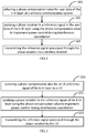
- FIG.1 is a flowchart of a signal transmission process in accordance with embodiments of the present application.
- the method may include the following procedures.
- a phase compensation value may be selected for user data of the k-th layer in a wireless communication system.
- the phase compensation value is for adjusting or modifying the phase of user data of the k-th layer.
- k may be selected from 1 and M.
- M is smaller than or equal to K.
- K is the total number of layers of user data in the wireless communication system.
- user data of the K layers may correspond to K users, and user data of each layer is transmitted for one user.
- User data in each layer is referred to as a data flow.
- user data of a first layer and user data of a second layer may be regarded as two data flows independent from each other, and may cause interference to each other.
- user data of the K layers may correspond to P users (P ⁇ K), i.e., a plurality of layers of user data may be transmitted for one user.
- user data of each layer may include a type of signal, i.e., reference signal.
- the reference signal is a signal known to both a transmitting end and a receiving end. After sent to a receiving end by a transmitting end, the reference signal may be used by the receiving end for channel estimation of the wireless channel between the transmitting end and the receiving end.
- the reference signal may be a Demodulation Reference Signal (DMRS).
- DMRS Demodulation Reference Signal
- SRS Sounding Reference Signal
- user data on each layer may include two types of signals, i.e., reference signal and data signal.
- a data signal is the signal that the transmitting end actually expects to provide to the receiving end. Content of the data signal is unknown to the receiving end. The receiving end requires the result of the channel estimation for correctly recovering the data signal.
- processing of signals e.g., a data signal, a reference signal, or the like, may be carried out in unit of symbol.
- phase rotation may be applied to a reference signal in user data of the k-th layer using the phase compensation value, so as to implement power control during interference cancellation.
- the reference signal after interference cancellation on a transmitter side has a signal power within a pre-defined power threshold. That is, it is necessary to find for the reference signal a phase compensation value which satisfies a power control requirement.
- the reference signal processed through the phase rotation may be transmitted via the wireless channel.
- user data of each layer may be processed through the procedures in the above steps 101-103, and the reference signal in the user data of each layer may have a phase compensation value.
- signal transmission may be performed for M users according to the method of various embodiments, i.e., applying power control to a reference signal using phase rotation, and power control to a data signal using a modulo operation.
- signals of the users may be processed through a linear coding mechanism, e.g., zero-forcing algorithm, or the like, before transmission.
- the capital letter K represents the total number of layers of user data
- the lowercase k represents user data of a certain layer among the K layers, i.e., K and k have different meanings.
- FIG.2 is a flowchart of a signal transmission process performed by user equipment (UE) in accordance with embodiments of the present application.
- a UE may select a phase compensation value for an uplink (UL) reference signal of the k-th layer.
- the reference signal of the k-th layer may be processed through phase rotation using the phase compensation value to make the reference signal processed through interference cancellation on a transmitter side have a signal power within a pre-defined power threshold.
- the UE may transmit the reference signal processed through phase rotation.
- the reference signal may be SRS.
- k may be selected from 1 to K.
- K is the total number of layers of uplink reference signals in the wireless communication system.
- the UE may have at least K transmitting antennae for transmitting the K layers of reference signals.
- the UE may have T transmitting antennae, and T is larger than or equal to K.
- the procedures of the above steps 201-203 may be applied to some uplink reference signals in the wireless communication system, i.e., k may be selected from 1 to M, M ⁇ K.
- FIG. 3 is a schematic diagram illustrating a process of precoding and transmitting a reference signal performed by a UE in accordance with embodiments of the present application.
- an original reference signal may be processed through phase rotation using a phase compensation value provided by a phase searching module 306 to obtain a corrected reference signal.
- a feedback interference signal provided by an interference canceling module 304 may be removed from the corrected reference signal to obtain an output reference signal.
- the output reference signal may be provided respectively to the interference removing module 304 and the feedforward processing module 207 at step 303.
- the interference canceling module 304 may store the output reference signal of each layer for feeding back the accumulated interference from the first layer to the (k-1)-th layer to facilitate processing of the reference signal of the k-th layer.
- the feedforward processing module 307 may process the output reference signal through feedforward to obtain a reference signal after the feedforward processing.
- the transposition of an UL channel H may be processed through QR decomposition to obtain a matrix Q and a matrix S , as shown in formula (1).
- the matrix Q serving as a feedforward processing matrix, may be multiplied by the output reference signal to obtain the reference signal after the feedforward processing.
- Q may be a unitary matrix.
- the reference signal after the feedforward processing may be processed through power normalization, and transmitted through the uplink channel H at step 309.
- the power checking module 305 may determine whether the output reference signal generated at step 305 exceeds a threshold, and provide a judging result to the phase searching module 306.
- the phase searching module 306 may select a phase compensation value for the reference signal of each layer, and decide whether to re-select a phase compensation value for the reference signal of a certain layer based on the judging result provided by the power checking module 305.
- FIG. 4 is a schematic diagram of vectors illustrating applying phase rotation before interference cancellation to a reference signal in accordance with embodiments of the present application.
- the interference cancellation may be performed according to formula (2).
- x RS , k d RS , k e j ⁇ k ⁇ ⁇ l ⁇ 1 k ⁇ 1 B k , l x RS , l
- x RS,k is the output reference signal 404 after interference cancellation and phase adjustment.
- d RS,k is the original reference signal 401 of the k-th layer, e.g., the to-be-transmitted reference signal of the k-th user, which is a signal planned by the UE and the base station.
- the feedback interference signal 403 is the accumulated interference which is suffered by the reference signal of the k-th layer and caused by reference signals from the first layer to the (k-1)-th layer.
- B k,l is an element in the k-th row and the l-th column of a feedback processing matrix B .
- the matrix B may be obtained from calculation according to formulae (3) and (4).
- S k,k is an element in the k-th row and the k-th column of matrix S which is obtained from calculation according to formula (1).
- matrix B may be obtained according to formula (4).
- the second output signal 405 processed through interference cancellation without phase adjustment has an increased signal power.
- the difference between the corrected reference signal 402 and the feedback interference signal 403, i.e., the output reference signal 404 does not have obvious power divergence.
- FIG.5 is a flowchart of a signal transmission process performed by a base station in accordance with embodiments of the present application.
- the method may include the following procedures.
- a base station may select a phase compensation value for downlink (DL) user data of the k-th layer.
- k may be selected from 1 to M.
- M is smaller than or equal to K.
- K is the total number of layers of user data transmitted by the base station.
- the reference signal in user data of the k-th layer may be processed through phase rotation using the phase compensation value to make the reference signal processed through interference cancellation on a transmitter side have a signal power within a pre-defined power threshold.
- a data signal in the user data of the k-th layer may be modulated using the phase compensation value. It can be seen that, a reference signal and a data signal which belong to user data of the same layer may be processed using the same phase compensation value during precoding.
- the base station may transmit the reference signal processed through the phase rotation and the modulated data signal.
- the reference signal may be DMRS.
- the K layers of user data may correspond to K users.
- the procedures in steps 501-504 may be performed for each user to select a phase compensation value for each user and to apply phase rotation and interference cancellation to the reference signal and the data signal of each user.
- FIG. 6 is a schematic diagram illustrating a process of precoding and transmitting a data signal and a reference signal by a base station in accordance with embodiments of the present application.
- precoding may function to: decouple signals of different UEs during signal transmission to suppress or eliminate the interference in the received signal of each UE; make a transmitted beam of each UE match the channel vector of the UE to increase the effective signal power received by each UE.
- an original reference signal of the k-th layer may be processed through phase rotation using a phase compensation value provided by the phase searching module 606 to obtain a corrected reference signal of the k-th layer.
- a first interference signal provided by the interference canceling module 604 may be removed from the corrected reference signal to obtain an output reference signal.
- the output reference signal may be provided respectively to the interference removing module 604 and the feedforward processing module 607 at step 603.
- the reference signal after the feedforward processing generated by the feedforward processing module 607 may be processed through power normalization at step 608, and then transmitted through the DL channel H at step 609.
- the matrix H has a dimension of K ⁇ T.
- the reference signal vector x RS of the base station may be defined according to formula (5).
- the transmitted reference signal y RS may be as shown in formula (6).
- P tx is a power normalization factor.
- y RS 1 P tx Qx RS
- the power checking module 605 may determine whether the output reference signal generated at step 602 exceeds a threshold, and provide a judging result to the phase searching module 606.
- the phase searching module 606 may select a phase compensation value for user data of each layer, and decide whether to re-select a phase compensation value for the user data of a certain layer based on the judging result provided by the power checking module 605.
- the phase searching module 606 may re-select for the user data of the k-th layer a phase compensation value that has not been tried, and perform the procedures in steps 601-606 again.
- the output reference signal of the k-th layer may be obtained from calculations according to formula (1), which is not elaborated herein.
- an original data signal of the k-th layer may be processed through phase rotation using a phase compensation value provided by the phase searching module 606 to obtain a corrected data signal.
- a second interference signal provided by a second interference canceling module 614 may be removed from the corrected data signal to obtain an output data signal.
- the output data signal is processed through a modulo operation, i.e., adding the output data signal to a modulo vector, to obtain a data signal after modulo operation.
- the modulo vector has been processed through the same phase rotation with that applied to the original data signal using the phase compensation value provided by the phase searching module 606.
- the data signal after modulo operation may be provided at step 613 to the second interference canceling module 614 and the feedforward processing module 607 respectively.
- the data signal after modulo operation of step 612 may be obtained according to formula (7).
- x Data,k is the data signal after modulo operation in the user data of the k-th layer.
- d Data,k is the original data signal, i.e., the data signal to be transmitted.
- ⁇ k is the phase compensation value of the user data of the k-th layer.
- Mod is related with the modulation order of d Data,k . For example, for Quadrature Phase Shift Keyin (QPSK) modulation, Mod is 4; for 16 Quadrature Amplitude Modulation (16QAM), Mod is 16.
- p I and p Q are both used in the modulo operation. In an example, p I and p Q are both integers, and may be calculated according to a Tomlinson-Harashima Precoding (THP) process.
- B k,l is an element in the k-th row and the l-th column of a feedback processing matrix B.
- the matrix B may be obtained by calculation according to formulae (3) and (4).
- Data signal vector x Data may be as shown in formula (8). Accordingly, the transmit data signal y Data may be as shown in formula (9).
- the power normalization may be implemented as follows.
- the maximum power of each element in formulae (10) and (11) may be determined according to formula (12).
- y ' RS,k is the k-th element of y ' RS
- y ' Data,k is the k-th element of y ' Data .
- the maximum power P of all elements in only y ' RS may be calculated, and then the power normalization factor P tx may be obtained through calculation according to formula (13).
- the modulo operation at step 612 may control the signal power of the data signal in the user data to avoid power amplification of the data signal after interference cancellation.
- power control using a modulo operation similar to that in step 612 may damage amplitude information in the reference signal, thus affects the usage of the reference signal in channel estimation. That is, the receiving end cannot effectively perform channel estimation using the reference signal which has been processed through the modulo operation.
- various embodiments implement power control of a reference signal through phase rotation of step 601 while performing interference cancellation of the reference signal. That is, during interference cancellation, the reference signal and the data signal in user data are processed through different power control procedures that respectively suit the characteristics of different types of signals in the user data.
- the reference signal is processed through the phase rotation
- the data signal is also processed through the same phase rotation.
- the base station may apply phase rotation to the data signal in the user data of the k-th layer using the phase compensation value of the reference signal in the user data of the k-th layer (as shown in step 610), and also apply the phase rotation to the pre-defined modulo vector using the phase compensation value (as shown in step 615).
- the base station may utilize the modulo vector processed through the phase rotation to perform a modulo operation on the data signal processed through the phase rotation to obtain the modulated data signal.
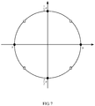
- the phase compensation value may be selected from a pre-defined set of candidate phases.
- FIG. 7 is a schematic diagram illustrating a candidate phase set in accordance with embodiments of the present disclosure.
- the candidate phase set may be In another example, the candidate phase set may be In an example, X candidate phases may be evenly selected from an available phase range to form the candidate phase set. In an example, the available phase range may be 0-2 ⁇ .
- Y candidate phases may be randomly selected from the available phase range to from the candidate phase set, and the candidate phase set may be searched to determine the phase compensation value of the user data of the k-th layer. It can be seen that, the complexity of phase searching can be reduced by determining a candidate phase set and then searching the candidate phase set for a phase compensation value for user data.
- FIG.8 is a flowchart illustrating a process of phase processing of a reference signal in accordance with embodiments of the present application.
- the method may include the following procedures. It is supposed there are a total of M layers of user data, and user data of each layer includes a reference signal. A group of phase compensation value ( ⁇ 1 ,..., ⁇ k ,..., ⁇ M ) is to be found out for the group of reference signals to make the output powers of the group of reference signals are all smaller than a threshold.
- a phase compensation value may be selected for a reference signal in user data of the k-th layer.
- phase rotation may be applied to the reference signal in the user data of the k-th layer using the phase compensation value.
- the procedure in step 802 may be similar to that in step 601.
- step 803 interference suffered by the reference signal in the user data of the k-th layer which is caused by reference signals in user data from the first layer to the (k-1)-th layer in the M layers may be removed.
- the procedure in step 803 may be similar to that in steps 602 and 604.
- the interference which is suffered by the user data of the k-th layer and caused by user data in layers from the first layer to the (k-1)-th layer is referred to as accumulated reference.
- the power checking module 605 may judge whether the power of the reference signal in the user data of the k-th layer after the interference cancellation exceeds the pre-defined power threshold, and perform the procedure in step 805 when the power does not exceed the threshold.
- the power checking in step 804 may include: determining whether the square of the modulus of the reference signal x RS,k processed through interference cancellation is smaller than a defined value E, i.e., determining whether the formula (14) is satisfied.
- the power checking in step 804 may include: determining whether the absolute value of the real part and the imaginary part of x RS,k is less than the defined value E, i.e., determining whether the formulae (15) and (16) are satisfied at the same time.
- step 805 it is judged whether k equals M. If k does not equal M, the procedure in step 806 may be performed. If k equals M, the phase processing may be ended.
- step 806 the k is modified to (k+1), and the procedure in step 801 may be performed.
- step 807 when the judging result in step 804 indicates the signal power exceeds the threshold, the procedure in step 807 may be performed.
- step 807 it is judged whether in the candidate phase set there is a candidate phase value that has not been tried for the k-th layer user data. If there is such a candidate phase value, the procedure in step 808 may be performed. If there is no such candidate phase value, the procedure in step 809 may be performed.
- step 808 re-selection of the phase compensation value may be performed, and the procedure in step 802 may be performed.
- step 809 it is judged whether k equals 1. If k does not equal 1, the procedure in step 810 may be performed. If k equals 1, the procedure in step 812 may be performed.
- k may be modified to (k-1).
- re-selection of the phase compensation value may be performed.
- the procedure in step 802 may be performed.
- the procedure in step 807 may be performed after execution of the procedure in step 810. It can be seen that, the step 810 utilizes a rollback mechanism which can also reduce the complexity of phase searching.
- algorithmic revision may be performed.
- the algorithmic revision may include: calculating the cross-correlation between user data of the M layers; for two layers whose user data has a cross-correlation exceeding a pre-defined value, deleting user data of one of the two layers from the M layers of user data, and performing the procedures in steps 801 to 811 again for the user data set after the deletion. For example, when the cross-correlation between user data 1 and user data 3 and the cross-correlation between user data 2 and user data 3 both exceed the pre-defined value, a user data set of (M-1) layers can be obtained by deleting user data 3, and the procedures in steps 801-811 may be performed again on the user data set of (M-1) layers. To ensure fairness, user data 3 may be transmitted using resources such as a subsequent time slot or another frequency band, or the like. It should be noted that, the algorithmic revision may be executed more than once until a group of phase compensation values that meet the power control requirement is found.
- the algorithmic revision may be carried out by setting phase compensation values to 0, and the power control processing of the reference signals of various embodiments may be ended. That is, phase rotation may not be applied to the reference signals. Accordingly, the signal power of the reference signals may be controlled to a certain degree in the stage of power normalization in steps 308 and 608.
- the procedures in step 801 and steps 805-811 may be performed by the phase searching module 606.
- the re-selection in steps 808 and 811 refers to using a candidate phase value that has not been tried for the user data of the k-th layer.
- the algorithmic revision may be carried out in a manner which minimizes the maximum output power, and the power control processing of the reference signal in various embodiments may be ended. That is, the selected is a group of phase compensation values which makes a reference signal in user data of a layer that has the maximum output power of reference signal has the minimum output power.
- the layer that has the maximum output power of reference signal refers to a layer whose reference signal has the maximum output power among the M layers of user data. Accordingly, the signal power of the reference signal may be controlled to a certain degree during power normalization in steps 308 and 608.
- the phase compensation value of the user data of the first layer may first be selected. Since the user data of the first layer does not suffer from interference caused by other users, the candidate phase value 0 can satisfy the requirement of the power control, thus 1/2 ⁇ , ⁇ and 3/2 ⁇ are candidate phase values that have not been tried for the user data of the first layer. During selection of the phase compensation value for user data of the second layer, it may be determined the candidate phase value 0 cannot satisfy the power control requirement while the candidate phase value 1/2 ⁇ can satisfy the power control requirement.
- phase compensation value of the user data of the second layer may be set to 3/2 ⁇ , and re-selection of a phase compensation value may be performed for the next layer (i.e., the layer 3 of user data).
- the searching may be repetitively performed until a phase compensation value that can satisfy the power control requirement is found for each layer of user data, which serves as the final phase compensation value.
- multiple candidate phase sets may be set up.
- the process as shown in FIG. 8 may be performed using a second candidate phase set.
- the second candidate phase set may be larger than the first candidate phase set.
- the first candidate phase set may have a size of 4
- the second candidate phase set may have a size of 8.
- the first candidate phase set may be
- a data signal in user data may be processed through phase rotation at the same time of the phase rotation of the reference signal. That is, in steps 801, 808 and 811, the procedures in steps 610 to 615 of FIG.
- phase compensation value selected in steps 801, 808 and 811 may not be the final phase compensation value
- the data signal in the user data of the k-th layer may be processed through the procedures of steps 610 to 615 more than once.
- the procedures in steps 610 to 615 of FIG. 6 may be carried out to precoding the data signals 1 to M after it is determined k equals M in step 805. That is, precoding of the reference signal may be carried out first, and precoding of the data signals may be carried out using the final phase compensation values after the final phase compensation values are found out.
- the phase searching module 606 may store the phase compensation values for all of the M user data, so that the phase compensation values, which meet the power control requirement, found for the user data of all the layers may be provided for the data signals 1 to M for phase rotation after phase processing of the reference signals.
- FIG. 9 is a schematic diagram illustrating implementing signal transmission using non-linear precoding in accordance with embodiments of the present application.
- the non-linear precoding may be the THP scheme.
- a base station applies non-linear precoding 901 to an original reference signal to obtain a coded reference signal.
- the non-linear precoding 901 includes processing of the reference signal, such as phase rotation 911, or the like.
- a coded reference signal may be obtained.
- the non-linear precoding 902 includes processing of the data signal, such as modulo operation 912, phase rotation 922, or the like.
- the number of downlink ports may be smaller than K, i.e., the non-linear precoding may increase spatial re-use rate of downlink ports and reduce reference signal overhead.
- the user data may be processed through antenna mapping 904 before being transmitted.
- the base station may inform the UE of the precoding scheme through downlink control information.
- the UE may apply a corresponding modulo operation to received user data after receiving the user data of the K layers.
- FIG. 10 is a schematic diagram illustrating modules of a base station 1000 in accordance with embodiments of the present application.
- the base station 1000 may include: a processor 1001, non-transitory machine-readable storage medium 1002, and a transmitting unit 1003.
- a program module 1004 is stored in the non-transitory machine-readable storage medium 1002, and may be executed by the processor 1001.
- the program module 1004 may be configured to: select a phase compensation value for user data of the k-th layer of the base station 1000.
- the reference signal in user data of the k-th layer may be processed through phase rotation according to the phase compensation value to make the reference signal processed through interference cancellation on a transmitter side have a signal power within a pre-defined power threshold.
- the data signal in the user data of the k-th layer may be modulated using the phase compensation value.
- modulating the data signal using the phase compensation value may include: applying phase rotation to the data signal using the phase compensation value, and applying phase rotation to a modulo vector.
- k may be within 1 to K.
- K is the total number of layers of user data in the wireless communication system.
- k may be between 1 and M, and M is smaller than K. That is, the phase rotation may be applied to a portion of user data of all the layers of base station 1000.
- the transmitting unit 1003 may be configured to: transmit the reference signal processed through the phase rotation and the modulated data signal.
- the transmitting unit 1003 may include an antenna.
- operations performed by the base station 1000 may be similar to those described with reference to FIG. 5, FIG. 6 and the like, and are not elaborated herein.
- FIG. 11 is a schematic diagram illustrating modules of a base station which performs non-linear precoding in accordance with embodiments of the present application.
- the base station 1100 may include: a processor 1001, non-transitory machine-readable storage medium 1002, and a transmitting unit 1003.
- a program module 1104 may be stored in the non-transitory machine-readable storage medium 1002, and may be executed by the processor 1001.
- the program module 1104 may be configured to perform:
- the program module 1104 may find out the final phase compensation value for user data of each layer one by one according to the order of the serial numbers of user data of the M layers.
- the program module 1104 may include the following modules: a phase searching module 1114, a phase rotating module 1124, an interference canceling module 1134 and a power checking module 1144.
- the phase searching module 1114 may select the phase compensation value for the user data of the k-th layer from the candidate phase set.
- the procedure performed by the phase searching module 1114 may be similar to those in step 306, step 801 and steps 805-811.
- the phase rotating module 1124 may apply phase rotation to the reference signal in the user data of the k-th layer using the phase compensation value.
- the procedure performed by the phase rotating module 1124 may be similar to those in step 301 and step 802.
- the interference canceling module 1134 may remove accumulative interference which is suffered by the reference signal in the user data of the k-th layer and caused by reference signals in user data from the first layer to the (k-1)-th layer in the M layers.
- the procedure performed by the interference removing module 1134 may be similar to those in step 302 and step 803.
- the power checking module 1144 may judge whether the signal power of the reference signal in the user data of the k-th layer after the interference cancellation exceeds the pre-defined power threshold, and inform the phase searching module 1114 of a result of the judging.
- the phase searching module 1114 may modify k into (k+1) and selecting the phase compensation value for user data in the (k+1)-th layer from the candidate phase set when the signal power does not exceed the pre-defined threshold.
- the procedure performed by the power judging module 1144 may be similar to those in step 305 and step 804.
- FIG. 12 is a schematic diagram illustrating modules of UE 1200 in accordance with embodiments of the present application.
- the UE 1200 may include: a processor 1201, non-transitory machine-readable storage medium 1202, and a transmitting unit 1203.
- a program module 1204 may be stored in the non-transitory machine-readable storage medium 1202, and may be executed by the processor 1201.
- the program module 1204 may be configured to: select a phase compensation value for user data of the k-th layer in the UE 1200, apply phase rotation to the reference signal in the user data of the k-th layer to make the signal power of the reference signal processed through interference cancellation within a pre-defined power threshold.
- k may be within 1 to K.
- K is the total number of layers of user data in the UE 1200.
- k may be selected from 1 to M, and M is smaller than K. That is, the program module 1204 may apply phase processing to a portion of user data of all the layers.
- the transmitting unit 1203 may be configured to transmit the reference signal after the phase rotation.
- the transmitting unit 1203 may include an antenna.
- operations performed by the UE 1200 may be similar to those described with reference to FIG. 2 , FIG. 3 and the like, and are not elaborated herein.
- FIG. 13 is a schematic diagram illustrating modules of UE 1300 which applies power control while performing interference cancellation in accordance with embodiments of the present application.
- the UE 1300 may include: a processor 1201, non-transitory machine-readable storage medium 1202, and a transmitting unit 1203.
- a program module 1304 may be stored in the non-transitory machine-readable storage medium 1202, and may be executed by the processor 1201.
- the program module 1304 may be configured to perform:
- the program module 1304 may include the following modules: a phase searching module 1314, a phase rotating module 1324, an interference canceling module 1334 and a power checking module 1344.
- the phase searching module 1314 may select the phase compensation value for the user data of the k-th layer from the candidate phase set.
- the procedure performed by the phase searching module 1314 may be similar to those in step 801 and steps 805-811.
- the phase rotating module 1324 may apply phase rotation to the reference signal in the user data of the k-th layer using the phase compensation value.
- the procedure performed by the phase rotating module 1324 may be similar to those in step 802.
- the interference canceling module 1334 may remove accumulative interference which is suffered by the reference signal in the user data of the k-th layer and caused by reference signals in user data from the first layer to the (k-1)-th layer in the M layers.
- the procedure performed by the interference removing module 1334 may be similar to those in step 803.
- the power checking module 1344 may judge whether the signal power of the reference signal in the user data of the k-th layer processed through the interference cancellation exceeds the pre-defined power threshold, and inform the phase searching module 1314 of a result of the judging.
- the phase searching module 1314 may modify k into (k+1) and selecting the phase compensation value for user data in the (k+1)-th layer from the candidate phase set when the power does not exceed the pre-defined threshold.
- the procedure performed by the power judging module 1344 may be similar to those in step 804.
- embodiments of the present application also provide a program capable of making a computer to carry out the methods as shown in FIG. 1, FIG. 2 , FIG. 5 and FIG. 8 , and non-transitory machine-readable storage medium storing the program.
Landscapes
- Engineering & Computer Science (AREA)
- Signal Processing (AREA)
- Computer Networks & Wireless Communication (AREA)
- Quality & Reliability (AREA)
- Physics & Mathematics (AREA)
- Electromagnetism (AREA)
- Spectroscopy & Molecular Physics (AREA)
- Mobile Radio Communication Systems (AREA)
- Cable Transmission Systems, Equalization Of Radio And Reduction Of Echo (AREA)
Abstract
Description
- The present application relates to communication technology, and particularly to a signal transmission method of a wireless communication system, base station, user equipment.
- A wireless communication system, made up of a transmitting end, a receiving end and a wireless channel, transmits various signals using electromagnetic waves. At present, wireless communication systems have gradually evolved from the first, second, third, and fourth generations to the fifth generation (5G), and more types of wireless communication systems may emerge in the future. With developments in the technology, wireless communication systems are becoming more and more competent in supporting -multi-user transmissions. During the multi-user transmissions, interference between different users also appears. Regardless of whether the system is time division, frequency division, space division or code division, the presence of multi-layer user data results in interference between user data of different layers, and the interference may affect the restoration of signals at the receiving end. Therefore, there is increasing need for interference cancellation in wireless communication systems.
- Embodiments of the present application provide a signal transmission method of a wireless communication system, a base station and a user equipment (UE), to make a to-be-transmitted signal satisfy a power control requirement while applying interference cancellation to the signal.
- Embodiments provide a signal transmission method of a wireless communication system. The method may include:
- selecting a phase compensation value for user data of a k-th layer in the wireless communication system, applying phase rotation to a reference signal in the user data of the k-th layer using the phase compensation value to make the reference signal processed through interference cancellation on a transmitter side have a signal power within a pre-defined power threshold, wherein k is selected from 1 to M, M is smaller than or equal to K; K is the total number of layers of user data in the wireless communication system; and
- transmitting the reference signal processed through the phase rotation via a wireless channel.
- Embodiments provide a program. The program is capable of causing a computer to:
- select a phase compensation value for user data of a k-th layer in the wireless communication system, apply phase rotation to a reference signal in the user data of the k-th layer using the phase compensation value to make the reference signal processed through interference cancellation on a transmitter side have a signal power within a pre-defined power threshold, wherein k is selected from 1 to M, M is smaller than or equal to K; K is the total number of layers of user data in the wireless communication system; and
- transmit the reference signal processed through the phase rotation via a wireless channel.
- Embodiments provide a non-transitory machine-readable storage medium. The storage medium stores machine-readable instructions executable by a processor to:
- select a phase compensation value for user data of a k-th layer in the wireless communication system, apply phase rotation to a reference signal in the user data of the k-th layer using the phase compensation value to make the reference signal processed through interference cancellation on a transmitter side have a signal power within a pre-defined power threshold, wherein k is selected from 1 to M, M is smaller than or equal to K; K is the total number of layers of user data in the wireless communication system; and
- transmit the reference signal processed through the phase rotation via a wireless channel.
- Embodiments provide a base station. The base station may include: a processor; non-transitory machine-readable storage medium; a program module stored in the non-transitory machine-readable storage medium and capable of being executed by the processor; and a transmitting unit;
wherein the program module is configured to: - select a phase compensation value for user data of a k-th layer in the base station; wherein k is within 1 to M, M is smaller than or equal to K; K is the total number of layers of user data in the wireless communication system; and
- apply phase rotation to a reference signal in user data of the k-th layer using the phase compensation value to make the reference signal processed through interference cancellation on a transmitter side have a signal power within a pre-defined power threshold; and
- modulate a data signal in the user data of the k-th layer using the phase compensation value;
- the transmitting unit is configured to: transmit the reference signal processed through the phase rotation and the modulated data signal.
- Embodiments provide a UE. The UE may include: a processor; non-transitory machine-readable storage medium; a program module stored in the non-transitory machine-readable storage medium and capable of being executed by the processor; and a transmitting unit;
wherein the program module is configured to: - select a phase compensation value for user data of the k-th layer in the UE, apply phase rotation to a reference signal in the user data of the k-th layer to make the reference signal processed through interference cancellation have a signal power within a pre-defined power threshold; wherein k is within 1 to M, M is smaller than or equal to K; K is the total number of layers of user data in the wireless communication system; and
- the transmitting unit is configured to: transmit the reference signal processed through the phase rotation.
- Embodiments provide a base station. The base station may include:
- a phase searching module, to select a phase compensation value for user data of a k-th layer in the base station to make a reference signal in the user data of the k-th layer processed through phase rotation using the phase compensation value and interference cancellation have a signal power within a pre-defined power threshold; wherein k is within 1 to M, M is smaller than or equal to K; K is the total number of layers of user data in the base station;
- a phase rotating module, to apply phase rotation to the reference signal in the user data of the k-th layer using the phase compensation value;
- an interference canceling module, to apply interference cancellation to the reference signal processed through the phase rotation;
- a power checking module, to judge whether the reference signal after the interference cancellation has a signal power exceeding the pre-defined power threshold, and informing the phase searching module of a judging result;
- a modulating module, to modulate a data signal in the user data of the k-th layer using the phase compensation value; and
- a transmitting unit, to transmit the reference signal processed through the phase rotation and the modulated data signal.
- Embodiments provide a UE. The UE may include:
- a phase searching module, to select a phase compensation value for user data of a k-th layer in the UE to make a reference signal in the user data of the k-th layer processed through phase rotation using the phase compensation value and interference cancellation have a signal power within a pre-defined power threshold; wherein k is within 1 to M, M is smaller than or equal to K; K is the total number of layers of user data in the base station;
- a phase rotating module, to apply phase rotation to the reference signal in the user data of the k-th layer using the phase compensation value;
- an interference canceling module, to apply interference cancellation to the reference signal processed through the phase rotation;
- a power checking module, to judge whether the reference signal processed through the interference cancellation has a signal power exceeding the pre-defined power threshold, and informing the phase searching module of a judging result; and
- a transmitting unit, to transmit the reference signal processed through the phase rotation.
-
-
FIG.1 is a flowchart of a signal transmission process in accordance with embodiments of the present application; -
FIG.2 is a flowchart of a signal transmission process performed at a UE in accordance with embodiments of the present application; -
FIG. 3 is a schematic diagram illustrating precoding reference signals before transmission by a UE in accordance with embodiments of the present application; -
FIG. 4 is a schematic diagram of vectors illustrating applying phase rotation before interference cancellation to a reference signal in accordance with embodiments of the present application; -
FIG.5 is a flowchart illustrating a signal transmission method performed by a base station in accordance with embodiments of the present application; -
FIG. 6 is a schematic diagram illustrating a process of precoding and transmitting a data signal and a reference signal by a base station in accordance with embodiments of the present application; -
FIG. 7 is a schematic diagram illustrating a candidate phase set in accordance with embodiments of the present disclosure; -
FIG.5 is a flowchart illustrating a process of phase processing of a reference signal in accordance with embodiments of the present application; -
FIG. 9 is a schematic diagram illustrating implementing signal transmission using non-linear precoding in accordance with embodiments of the present application; -
FIG. 10 is a schematic diagram illustrating modules of a base station in accordance with embodiments of the present application; -
FIG. 11 is a schematic diagram illustrating modules of a base station which performs non-linear precoding in accordance with embodiments of the present application; -
FIG. 12 is a schematic diagram illustrating modules of a UE in accordance with embodiments of the present application; and -
FIG. 13 is a schematic diagram illustrating modules of a UE which applies power control while performing interference cancellation in accordance with embodiments of the present application. - This application is hereinafter further described in detail with reference to the accompanying drawings as well as embodiments so as to make the objective, technical solution and merits thereof more apparent.
- Various embodiments of the present application provide a signal transmission method in a wireless communication system. When applying interference cancellation on a transmitter side to a reference signal in user data, the signal power of the reference signal processed through interference cancellation can be kept within a proper range, e.g., within a pre-defined power threshold, by performing phase rotation to implement power control. According to an example, the wireless communication system may be a Multi-User Multiple-Input Multiple-Output (MU-MIMO) system, e.g., a high-rank MU-MIMO system. According to an example, the wireless communication system may also be a multi-user Code Division Multiple Access (CDMA) system, or a single-user multi-data flow system, or another wireless access network which requires interference cancellation (e.g., cancellation of inter-user interference or inter-layer interference, or the like).
-
FIG.1 is a flowchart of a signal transmission process in accordance with embodiments of the present application. The method may include the following procedures. - At
step 101, a phase compensation value may be selected for user data of the k-th layer in a wireless communication system. - In an example, the phase compensation value is for adjusting or modifying the phase of user data of the k-th layer. In an example, k may be selected from 1 and M. M is smaller than or equal to K. K is the total number of layers of user data in the wireless communication system. In an example, user data of the K layers may correspond to K users, and user data of each layer is transmitted for one user. User data in each layer is referred to as a data flow. It should be noted that user data of a first layer and user data of a second layer may be regarded as two data flows independent from each other, and may cause interference to each other. In another example, user data of the K layers may correspond to P users (P<K), i.e., a plurality of layers of user data may be transmitted for one user.
- In an example, user data of each layer may include a type of signal, i.e., reference signal. In an example, the reference signal is a signal known to both a transmitting end and a receiving end. After sent to a receiving end by a transmitting end, the reference signal may be used by the receiving end for channel estimation of the wireless channel between the transmitting end and the receiving end. In an example, the reference signal may be a Demodulation Reference Signal (DMRS). In another example, the reference signal may be a Sounding Reference Signal (SRS).
- In an example, user data on each layer may include two types of signals, i.e., reference signal and data signal. According to an example, a data signal is the signal that the transmitting end actually expects to provide to the receiving end. Content of the data signal is unknown to the receiving end. The receiving end requires the result of the channel estimation for correctly recovering the data signal. In an example, processing of signals, e.g., a data signal, a reference signal, or the like, may be carried out in unit of symbol.
- At
step 102, phase rotation may be applied to a reference signal in user data of the k-th layer using the phase compensation value, so as to implement power control during interference cancellation. - In an example, after phase rotation is applied to the reference signal, it is required that the reference signal after interference cancellation on a transmitter side has a signal power within a pre-defined power threshold. That is, it is necessary to find for the reference signal a phase compensation value which satisfies a power control requirement.
- At
step 103, the reference signal processed through the phase rotation may be transmitted via the wireless channel. - In an example, in the M layers of user data, user data of each layer may be processed through the procedures in the above steps 101-103, and the reference signal in the user data of each layer may have a phase compensation value. In an example, when M is smaller than K, signal transmission may be performed for M users according to the method of various embodiments, i.e., applying power control to a reference signal using phase rotation, and power control to a data signal using a modulo operation. For the other (K-M) users, signals of the users may be processed through a linear coding mechanism, e.g., zero-forcing algorithm, or the like, before transmission. According to various embodiments, the capital letter K represents the total number of layers of user data, the lowercase k represents user data of a certain layer among the K layers, i.e., K and k have different meanings.
-
FIG.2 is a flowchart of a signal transmission process performed by user equipment (UE) in accordance with embodiments of the present application. - At
step 201, a UE may select a phase compensation value for an uplink (UL) reference signal of the k-th layer. - At
step 202, the reference signal of the k-th layer may be processed through phase rotation using the phase compensation value to make the reference signal processed through interference cancellation on a transmitter side have a signal power within a pre-defined power threshold. - At
step 203, the UE may transmit the reference signal processed through phase rotation. - In an example, the reference signal may be SRS. In an example, k may be selected from 1 to K. K is the total number of layers of uplink reference signals in the wireless communication system. Accordingly, the UE may have at least K transmitting antennae for transmitting the K layers of reference signals. For example, the UE may have T transmitting antennae, and T is larger than or equal to K. In an example, the procedures of the above steps 201-203 may be applied to some uplink reference signals in the wireless communication system, i.e., k may be selected from 1 to M, M<K.
-
FIG. 3 is a schematic diagram illustrating a process of precoding and transmitting a reference signal performed by a UE in accordance with embodiments of the present application. Atstep 301, an original reference signal may be processed through phase rotation using a phase compensation value provided by aphase searching module 306 to obtain a corrected reference signal. Atstep 302, a feedback interference signal provided by aninterference canceling module 304 may be removed from the corrected reference signal to obtain an output reference signal. The output reference signal may be provided respectively to theinterference removing module 304 and the feedforward processing module 207 atstep 303. In an example, theinterference canceling module 304 may store the output reference signal of each layer for feeding back the accumulated interference from the first layer to the (k-1)-th layer to facilitate processing of the reference signal of the k-th layer. - The
feedforward processing module 307 may process the output reference signal through feedforward to obtain a reference signal after the feedforward processing. In an example, the transposition of an UL channel H may be processed through QR decomposition to obtain a matrix Q and a matrix S, as shown in formula (1). The matrix Q , serving as a feedforward processing matrix, may be multiplied by the output reference signal to obtain the reference signal after the feedforward processing. In an example, Q may be a unitary matrix.
- At
step 308, the reference signal after the feedforward processing may be processed through power normalization, and transmitted through the uplink channel H atstep 309. - The
power checking module 305 may determine whether the output reference signal generated atstep 305 exceeds a threshold, and provide a judging result to thephase searching module 306. Thephase searching module 306 may select a phase compensation value for the reference signal of each layer, and decide whether to re-select a phase compensation value for the reference signal of a certain layer based on the judging result provided by thepower checking module 305. -
FIG. 4 is a schematic diagram of vectors illustrating applying phase rotation before interference cancellation to a reference signal in accordance with embodiments of the present application. In an example, the interference cancellation may be performed according to formula (2).
- In the formula, xRS,k is the
output reference signal 404 after interference cancellation and phase adjustment. dRS,k is theoriginal reference signal 401 of the k-th layer, e.g., the to-be-transmitted reference signal of the k-th user, which is a signal planned by the UE and the base station.
reference signal 402 of the k-th layer, and θk is the phase compensation value of the reference signal of the k-th layer.
feedback interference signal 403. For the reference signal of the k-th layer, thefeedback interference signal 403 is the accumulated interference which is suffered by the reference signal of the k-th layer and caused by reference signals from the first layer to the (k-1)-th layer. Bk,l is an element in the k-th row and the l-th column of a feedback processing matrix B . The matrix B may be obtained from calculation according to formulae (3) and (4).

- It should be noted that, in formula (3), Sk,k is an element in the k-th row and the k-th column of matrix S which is obtained from calculation according to formula (1). In an example, after the matrices S and G are obtained according to formulae (1) and (3), matrix B may be obtained according to formula (4).
- It can be seen that, since there is a big phase difference between the
original reference signal 401 and thefeedback reference signal 403, thesecond output signal 405 processed through interference cancellation without phase adjustment has an increased signal power. In contrast, the difference between the correctedreference signal 402 and thefeedback interference signal 403, i.e., theoutput reference signal 404, does not have obvious power divergence. -
FIG.5 is a flowchart of a signal transmission process performed by a base station in accordance with embodiments of the present application. The method may include the following procedures. - At
step 501, a base station may select a phase compensation value for downlink (DL) user data of the k-th layer. k may be selected from 1 to M. M is smaller than or equal to K. K is the total number of layers of user data transmitted by the base station. - At
step 502, the reference signal in user data of the k-th layer may be processed through phase rotation using the phase compensation value to make the reference signal processed through interference cancellation on a transmitter side have a signal power within a pre-defined power threshold. - At
step 503, a data signal in the user data of the k-th layer may be modulated using the phase compensation value. It can be seen that, a reference signal and a data signal which belong to user data of the same layer may be processed using the same phase compensation value during precoding. - At
step 504, the base station may transmit the reference signal processed through the phase rotation and the modulated data signal. - In an example, the reference signal may be DMRS. In an example, the K layers of user data may correspond to K users. The procedures in steps 501-504 may be performed for each user to select a phase compensation value for each user and to apply phase rotation and interference cancellation to the reference signal and the data signal of each user.
-
FIG. 6 is a schematic diagram illustrating a process of precoding and transmitting a data signal and a reference signal by a base station in accordance with embodiments of the present application. In multi-user environment, precoding may function to: decouple signals of different UEs during signal transmission to suppress or eliminate the interference in the received signal of each UE; make a transmitted beam of each UE match the channel vector of the UE to increase the effective signal power received by each UE. - At
step 601, an original reference signal of the k-th layer may be processed through phase rotation using a phase compensation value provided by thephase searching module 606 to obtain a corrected reference signal of the k-th layer. Atstep 602, a first interference signal provided by theinterference canceling module 604 may be removed from the corrected reference signal to obtain an output reference signal. The output reference signal may be provided respectively to theinterference removing module 604 and thefeedforward processing module 607 atstep 603. The reference signal after the feedforward processing generated by thefeedforward processing module 607 may be processed through power normalization atstep 608, and then transmitted through the DL channel H atstep 609. In an example, when a base station has a total of K downlink data flows, and is configured with T transmitting antennae, the matrix H has a dimension of K × T. The reference signal vector x RS of the base station may be defined according to formula (5). In an example, when K is smaller than T, the vector x RS may be converted into a column vector with a dimension of T × 1 through zero-filling.
- In an example, through the
feedforward processing 607 and thepower normalization 608, the transmitted reference signal y RS may be as shown in formula (6). Ptx is a power normalization factor.
- The power checking module 605 may determine whether the output reference signal generated at
step 602 exceeds a threshold, and provide a judging result to thephase searching module 606. Thephase searching module 606 may select a phase compensation value for user data of each layer, and decide whether to re-select a phase compensation value for the user data of a certain layer based on the judging result provided by the power checking module 605. In an example, when the signal power of the output reference signal of the k-th layer exceeds a pre-defined threshold, thephase searching module 606 may re-select for the user data of the k-th layer a phase compensation value that has not been tried, and perform the procedures in steps 601-606 again. It should be noted that the output reference signal of the k-th layer may be obtained from calculations according to formula (1), which is not elaborated herein. - For a data signal, at
step 610, an original data signal of the k-th layer may be processed through phase rotation using a phase compensation value provided by thephase searching module 606 to obtain a corrected data signal. Atstep 611, a second interference signal provided by a secondinterference canceling module 614 may be removed from the corrected data signal to obtain an output data signal. Atstep 612, the output data signal is processed through a modulo operation, i.e., adding the output data signal to a modulo vector, to obtain a data signal after modulo operation. It should be noted that, atstep 615, the modulo vector has been processed through the same phase rotation with that applied to the original data signal using the phase compensation value provided by thephase searching module 606. Further, the data signal after modulo operation may be provided atstep 613 to the secondinterference canceling module 614 and thefeedforward processing module 607 respectively. - In an example, the data signal after modulo operation of
step 612 may be obtained according to formula (7).
- xData,k is the data signal after modulo operation in the user data of the k-th layer. dData,k is the original data signal, i.e., the data signal to be transmitted. θk is the phase compensation value of the user data of the k-th layer. Mod is related with the modulation order of dData,k. For example, for Quadrature Phase Shift Keyin (QPSK) modulation, Mod is 4; for 16 Quadrature Amplitude Modulation (16QAM), Mod is 16. pI and pQ are both used in the modulo operation. In an example, pI and pQ are both integers, and may be calculated according to a Tomlinson-Harashima Precoding (THP) process. Bk,l is an element in the k-th row and the l-th column of a feedback processing matrix B. The matrix B may be obtained by calculation according to formulae (3) and (4).
- Data signal vector x Data may be as shown in formula (8). Accordingly, the transmit data signal y Data may be as shown in formula (9).


- In an example, when there are a reference signal and a data signal, the power normalization may be implemented as follows. The maximum power of each element in formulae (10) and (11) may be determined according to formula (12). y' RS,k is the k-th element of y' RS , and y' Data,k is the k-th element of y' Data .


- When the maximum transmitting power of a transmitter is Pmax, the power normalization factor Ptx may be as follows:

- When there is only a reference signal, the maximum power P of all elements in only y' RS may be calculated, and then the power normalization factor Ptx may be obtained through calculation according to formula (13).
- It can be seen that, the modulo operation at
step 612 may control the signal power of the data signal in the user data to avoid power amplification of the data signal after interference cancellation. For the reference signal in the user data, however, power control using a modulo operation similar to that instep 612 may damage amplitude information in the reference signal, thus affects the usage of the reference signal in channel estimation. That is, the receiving end cannot effectively perform channel estimation using the reference signal which has been processed through the modulo operation. Hence, various embodiments implement power control of a reference signal through phase rotation ofstep 601 while performing interference cancellation of the reference signal. That is, during interference cancellation, the reference signal and the data signal in user data are processed through different power control procedures that respectively suit the characteristics of different types of signals in the user data. - Besides, it can be seen from
FIG. 6 that, the reference signal is processed through the phase rotation, and the data signal is also processed through the same phase rotation. Specifically, the base station may apply phase rotation to the data signal in the user data of the k-th layer using the phase compensation value of the reference signal in the user data of the k-th layer (as shown in step 610), and also apply the phase rotation to the pre-defined modulo vector using the phase compensation value (as shown in step 615). After that, the base station may utilize the modulo vector processed through the phase rotation to perform a modulo operation on the data signal processed through the phase rotation to obtain the modulated data signal. - The phase compensation value may be selected from a pre-defined set of candidate phases.
FIG. 7 is a schematic diagram illustrating a candidate phase set in accordance with embodiments of the present disclosure. For example, the candidate phase set may be In another example, the candidate phase set may be In an example, X candidate phases may be evenly selected from an available phase range to form the candidate phase set. In an example, the available phase range may be 0-2 π. In an example, Y candidate phases may be randomly selected from the available phase range to from the candidate phase set, and the candidate phase set may be searched to determine the phase compensation value of the user data of the k-th layer. It can be seen that, the complexity of phase searching can be reduced by determining a candidate phase set and then searching the candidate phase set for a phase compensation value for user data. -
FIG.8 is a flowchart illustrating a process of phase processing of a reference signal in accordance with embodiments of the present application. The method may include the following procedures. It is supposed there are a total of M layers of user data, and user data of each layer includes a reference signal. A group of phase compensation value (θ 1,...,θk ,...,θM ) is to be found out for the group of reference signals to make the output powers of the group of reference signals are all smaller than a threshold. - At
step 801, a phase compensation value may be selected for a reference signal in user data of the k-th layer. - At
step 802, phase rotation may be applied to the reference signal in the user data of the k-th layer using the phase compensation value. In an example, the procedure instep 802 may be similar to that instep 601. - At
step 803, interference suffered by the reference signal in the user data of the k-th layer which is caused by reference signals in user data from the first layer to the (k-1)-th layer in the M layers may be removed. In an example, the procedure instep 803 may be similar to that insteps - In an example, the interference which is suffered by the user data of the k-th layer and caused by user data in layers from the first layer to the (k-1)-th layer is referred to as accumulated reference.
- In
step 804, the power checking module 605 may judge whether the power of the reference signal in the user data of the k-th layer after the interference cancellation exceeds the pre-defined power threshold, and perform the procedure instep 805 when the power does not exceed the threshold. - In an example, the power checking in
step 804 may include: determining whether the square of the modulus of the reference signal xRS,k processed through interference cancellation is smaller than a defined value E, i.e., determining whether the formula (14) is satisfied.
- In an example, the power checking in
step 804 may include: determining whether the absolute value of the real part and the imaginary part of xRS,k is less than the defined value E, i.e., determining whether the formulae (15) and (16) are satisfied at the same time.

- At
step 805, it is judged whether k equals M. If k does not equal M, the procedure instep 806 may be performed. If k equals M, the phase processing may be ended. - At
step 806, the k is modified to (k+1), and the procedure instep 801 may be performed. - Further, when the judging result in
step 804 indicates the signal power exceeds the threshold, the procedure in step 807 may be performed. - At step 807, it is judged whether in the candidate phase set there is a candidate phase value that has not been tried for the k-th layer user data. If there is such a candidate phase value, the procedure in
step 808 may be performed. If there is no such candidate phase value, the procedure instep 809 may be performed. - At
step 808, re-selection of the phase compensation value may be performed, and the procedure instep 802 may be performed. - At
step 809, it is judged whether k equals 1. If k does not equal 1, the procedure instep 810 may be performed. If k equals 1, the procedure instep 812 may be performed. - At
step 801, k may be modified to (k-1). Atstep 811, re-selection of the phase compensation value may be performed. Then, the procedure instep 802 may be performed. In an example, the procedure in step 807 may be performed after execution of the procedure instep 810. It can be seen that, thestep 810 utilizes a rollback mechanism which can also reduce the complexity of phase searching. - At
step 812, algorithmic revision may be performed. In an example, the algorithmic revision may include: calculating the cross-correlation between user data of the M layers; for two layers whose user data has a cross-correlation exceeding a pre-defined value, deleting user data of one of the two layers from the M layers of user data, and performing the procedures insteps 801 to 811 again for the user data set after the deletion. For example, when the cross-correlation betweenuser data 1 anduser data 3 and the cross-correlation betweenuser data 2 anduser data 3 both exceed the pre-defined value, a user data set of (M-1) layers can be obtained by deletinguser data 3, and the procedures in steps 801-811 may be performed again on the user data set of (M-1) layers. To ensure fairness,user data 3 may be transmitted using resources such as a subsequent time slot or another frequency band, or the like. It should be noted that, the algorithmic revision may be executed more than once until a group of phase compensation values that meet the power control requirement is found. - In another example, the algorithmic revision may be carried out by setting phase compensation values to 0, and the power control processing of the reference signals of various embodiments may be ended. That is, phase rotation may not be applied to the reference signals. Accordingly, the signal power of the reference signals may be controlled to a certain degree in the stage of power normalization in
steps - In an example, the procedures in
step 801 and steps 805-811 may be performed by thephase searching module 606. In an example, the re-selection insteps - In an example, the algorithmic revision may be carried out in a manner which minimizes the maximum output power, and the power control processing of the reference signal in various embodiments may be ended. That is, the selected is a group of phase compensation values which makes a reference signal in user data of a layer that has the maximum output power of reference signal has the minimum output power. The layer that has the maximum output power of reference signal refers to a layer whose reference signal has the maximum output power among the M layers of user data. Accordingly, the signal power of the reference signal may be controlled to a certain degree during power normalization in
steps - It is supposed there are 3 layers of user data, and the candidate phase set is The phase compensation value of the user data of the first layer may first be selected. Since the user data of the first layer does not suffer from interference caused by other users, the
candidate phase value 0 can satisfy the requirement of the power control, thus 1/2 π, π and 3/2 π are candidate phase values that have not been tried for the user data of the first layer. During selection of the phase compensation value for user data of the second layer, it may be determined thecandidate phase value 0 cannot satisfy the power control requirement while thecandidate phase value 1/2 π can satisfy the power control requirement. When proceeding to the selection of the phase compensation value for the user data of the third layer, it may be determined all of the candidate phase values in the candidate phase set cannot satisfy the requirement of the power control, and the processing may rollback to the second layer to re-select a phase compensation value for the user data of the second layer. Then, π and 3/2 π may be respectively tried in phase rotation of the reference signal in user data of the second layer, and it may be found that thecandidate phase value 3/2 π can satisfy the power control requirement. Thus, the phase compensation value of the user data of the second layer may be set to 3/2 π, and re-selection of a phase compensation value may be performed for the next layer (i.e., thelayer 3 of user data). The searching may be repetitively performed until a phase compensation value that can satisfy the power control requirement is found for each layer of user data, which serves as the final phase compensation value. - In an example, multiple candidate phase sets may be set up. When phase compensation values that satisfy the requirement cannot be found in a first candidate phase set for all layers of user data to control the power of all reference signals, the process as shown in
FIG. 8 may be performed using a second candidate phase set. The second candidate phase set may be larger than the first candidate phase set. For example, the first candidate phase set may have a size of 4, the second candidate phase set may have a size of 8. In an example, the first candidate phase set may be In an example, a data signal in user data may be processed through phase rotation at the same time of the phase rotation of the reference signal. That is, insteps steps 610 to 615 ofFIG. 6 may be performed after a phase compensation value is selected for user data of the k-th layer. Since the phase compensation value selected insteps steps 610 to 615 more than once. - In another example, the procedures in
steps 610 to 615 ofFIG. 6 may be carried out to precoding the data signals 1 to M after it is determined k equals M instep 805. That is, precoding of the reference signal may be carried out first, and precoding of the data signals may be carried out using the final phase compensation values after the final phase compensation values are found out. Thephase searching module 606 may store the phase compensation values for all of the M user data, so that the phase compensation values, which meet the power control requirement, found for the user data of all the layers may be provided for the data signals 1 to M for phase rotation after phase processing of the reference signals. -
FIG. 9 is a schematic diagram illustrating implementing signal transmission using non-linear precoding in accordance with embodiments of the present application. In an example, the non-linear precoding may be the THP scheme. - A base station applies
non-linear precoding 901 to an original reference signal to obtain a coded reference signal. Specifically, thenon-linear precoding 901 includes processing of the reference signal, such asphase rotation 911, or the like. After thenon-linear precoding 902 of the original data signal, a coded reference signal may be obtained. Specifically, thenon-linear precoding 902 includes processing of the data signal, such as modulooperation 912,phase rotation 922, or the like. Taking M=K as an example, since the reference signals and the data signals in user data of the K layers have been processed through non-linear precoding, the user data of the K layers may be mapped to N downlink ports (step 903), where N is smaller than or equal to K. It can be seen that, the number of downlink ports, denoted by N, may be smaller than K, i.e., the non-linear precoding may increase spatial re-use rate of downlink ports and reduce reference signal overhead. Further, the user data may be processed throughantenna mapping 904 before being transmitted. In an example, the base station may inform the UE of the precoding scheme through downlink control information. Correspondingly, the UE may apply a corresponding modulo operation to received user data after receiving the user data of the K layers. -
FIG. 10 is a schematic diagram illustrating modules of abase station 1000 in accordance with embodiments of the present application. In an example, thebase station 1000 may include: aprocessor 1001, non-transitory machine-readable storage medium 1002, and atransmitting unit 1003. - A
program module 1004 is stored in the non-transitory machine-readable storage medium 1002, and may be executed by theprocessor 1001. In an example, theprogram module 1004 may be configured to: select a phase compensation value for user data of the k-th layer of thebase station 1000. Atstep 502, the reference signal in user data of the k-th layer may be processed through phase rotation according to the phase compensation value to make the reference signal processed through interference cancellation on a transmitter side have a signal power within a pre-defined power threshold. The data signal in the user data of the k-th layer may be modulated using the phase compensation value. In an example, modulating the data signal using the phase compensation value may include: applying phase rotation to the data signal using the phase compensation value, and applying phase rotation to a modulo vector. - In an example, k may be within 1 to K. K is the total number of layers of user data in the wireless communication system. In an example, k may be between 1 and M, and M is smaller than K. That is, the phase rotation may be applied to a portion of user data of all the layers of
base station 1000. - The
transmitting unit 1003 may be configured to: transmit the reference signal processed through the phase rotation and the modulated data signal. In an example, thetransmitting unit 1003 may include an antenna. - In an example, operations performed by the
base station 1000 may be similar to those described with reference toFIG. 5, FIG. 6 and the like, and are not elaborated herein. -
FIG. 11 is a schematic diagram illustrating modules of a base station which performs non-linear precoding in accordance with embodiments of the present application. In an example, thebase station 1100 may include: aprocessor 1001, non-transitory machine-readable storage medium 1002, and atransmitting unit 1003. - A
program module 1104 may be stored in the non-transitory machine-readable storage medium 1002, and may be executed by theprocessor 1001. In an example, theprogram module 1104 may be configured to perform: - A. selecting the phase compensation value for the user data of the k-th layer from a candidate phase set which includes multiple candidate phase values;
- B. applying phase rotation to the reference signal in the user data of the k-th layer using the phase compensation value;
- C. removing accumulated interference which is suffered by the reference signal in the user data of the k-th layer and caused by reference signals in user data from the first layer to the (k-1)-th layer in the M layers;
- D. judging whether the signal power of the reference signal in the user data of the k-th layer processed through interference cancellation exceeds the pre-defined power threshold; and
- E. when the signal power of the reference signal does not exceed the power threshold, modifying k to be (k+1) and returning to the procedure in step A when k#M; or ending the process when k=M; when the signal power of the reference signal exceeds the power threshold, re-selecting the phase compensation value and return to the procedure in step B.
- Through the above steps A-E, the
program module 1104 may find out the final phase compensation value for user data of each layer one by one according to the order of the serial numbers of user data of the M layers. - In an example, the
program module 1104 may include the following modules: aphase searching module 1114, aphase rotating module 1124, aninterference canceling module 1134 and apower checking module 1144. - The
phase searching module 1114 may select the phase compensation value for the user data of the k-th layer from the candidate phase set. In an example, the procedure performed by thephase searching module 1114 may be similar to those instep 306,step 801 and steps 805-811. - The
phase rotating module 1124 may apply phase rotation to the reference signal in the user data of the k-th layer using the phase compensation value. In an example, the procedure performed by thephase rotating module 1124 may be similar to those instep 301 andstep 802. - The
interference canceling module 1134 may remove accumulative interference which is suffered by the reference signal in the user data of the k-th layer and caused by reference signals in user data from the first layer to the (k-1)-th layer in the M layers. In an example, the procedure performed by theinterference removing module 1134 may be similar to those instep 302 andstep 803. - The
power checking module 1144 may judge whether the signal power of the reference signal in the user data of the k-th layer after the interference cancellation exceeds the pre-defined power threshold, and inform thephase searching module 1114 of a result of the judging. Thephase searching module 1114 may modify k into (k+1) and selecting the phase compensation value for user data in the (k+1)-th layer from the candidate phase set when the signal power does not exceed the pre-defined threshold. In an example, the procedure performed by thepower judging module 1144 may be similar to those instep 305 andstep 804. -
FIG. 12 is a schematic diagram illustrating modules ofUE 1200 in accordance with embodiments of the present application. In an example, theUE 1200 may include: aprocessor 1201, non-transitory machine-readable storage medium 1202, and atransmitting unit 1203. - A
program module 1204 may be stored in the non-transitory machine-readable storage medium 1202, and may be executed by theprocessor 1201. In an example, theprogram module 1204 may be configured to: select a phase compensation value for user data of the k-th layer in theUE 1200, apply phase rotation to the reference signal in the user data of the k-th layer to make the signal power of the reference signal processed through interference cancellation within a pre-defined power threshold. In an example, k may be within 1 to K. K is the total number of layers of user data in theUE 1200. In an example, k may be selected from 1 to M, and M is smaller than K. That is, theprogram module 1204 may apply phase processing to a portion of user data of all the layers. - The
transmitting unit 1203 may be configured to transmit the reference signal after the phase rotation. In an example, thetransmitting unit 1203 may include an antenna. - In an example, operations performed by the
UE 1200 may be similar to those described with reference toFIG. 2 ,FIG. 3 and the like, and are not elaborated herein. -
FIG. 13 is a schematic diagram illustrating modules ofUE 1300 which applies power control while performing interference cancellation in accordance with embodiments of the present application. In an example, theUE 1300 may include: aprocessor 1201, non-transitory machine-readable storage medium 1202, and atransmitting unit 1203. - A
program module 1304 may be stored in the non-transitory machine-readable storage medium 1202, and may be executed by theprocessor 1201. In an example, theprogram module 1304 may be configured to perform: - A. selecting the phase compensation value for the user data of the k-th layer from a candidate phase set which includes multiple candidate phase values;
- B. applying phase rotation to the reference signal in the user data of the k-th layer using the phase compensation value;
- C. removing accumulated interference which is suffered by the reference signal in the user data of the k-th layer and caused by reference signals in user data from the first layer to the (k-1)-th layer in the M layers;
- D. judging whether the signal power of the reference signal in the user data of the k-th layer after the interference cancellation exceeds the pre-defined power threshold; and
- E. when the power of the reference signal does not exceed the power threshold, modifying k to be (k+1) and returning to the procedure in step A when k#M; or ending the process when k=M; when the signal power of the reference signal exceeds the power threshold, re-selecting the phase compensation value and return to the procedure in step B.
- In an example, the
program module 1304 may include the following modules: a phase searching module 1314, a phase rotating module 1324, aninterference canceling module 1334 and a power checking module 1344. - The phase searching module 1314 may select the phase compensation value for the user data of the k-th layer from the candidate phase set. In an example, the procedure performed by the phase searching module 1314 may be similar to those in
step 801 and steps 805-811. - The phase rotating module 1324 may apply phase rotation to the reference signal in the user data of the k-th layer using the phase compensation value. In an example, the procedure performed by the phase rotating module 1324 may be similar to those in
step 802. - The
interference canceling module 1334 may remove accumulative interference which is suffered by the reference signal in the user data of the k-th layer and caused by reference signals in user data from the first layer to the (k-1)-th layer in the M layers. In an example, the procedure performed by theinterference removing module 1334 may be similar to those instep 803. - The power checking module 1344 may judge whether the signal power of the reference signal in the user data of the k-th layer processed through the interference cancellation exceeds the pre-defined power threshold, and inform the phase searching module 1314 of a result of the judging. The phase searching module 1314 may modify k into (k+1) and selecting the phase compensation value for user data in the (k+1)-th layer from the candidate phase set when the power does not exceed the pre-defined threshold. In an example, the procedure performed by the power judging module 1344 may be similar to those in
step 804. - In addition, embodiments of the present application also provide a program capable of making a computer to carry out the methods as shown in
FIG. 1, FIG. 2 ,FIG. 5 andFIG. 8 , and non-transitory machine-readable storage medium storing the program. - The foregoing are only preferred examples of the present disclosure and are not for use in limiting the protection scope thereof. All modifications, equivalent replacements or improvements in accordance with the spirit and principles of the present disclosure shall be included in the protection scope of the present disclosure.
Claims (20)
- A signal transmission method in a wireless communication system, comprising:selecting a phase compensation value for user data of a k-th layer of the wireless communication system, applying phase rotation to a reference signal in the user data of the k-th layer using the phase compensation value to make the reference signal processed through interference cancellation on a transmitter side have a signal power within a pre-defined power threshold, wherein k is within 1 to M, M is smaller than or equal to K; K is the total number of layers of user data in the wireless communication system; andtransmitting, via a wireless channel, the reference signal processed through the phase rotation.
- The method of claim 1, further comprising:
modulating a data signal in the user data of the k-th layer using the phase compensation value, and transmitting the modulated data signal. - The method of claim 2, wherein modulating the data signal in the user data of the k-th layer using the phase compensation value comprises:applying phase rotation to the data signal using the phase compensation value;applying phase rotation to a pre-configured modulo vector using the phase compensation value; andapplying a modulo operation to the data signal processed through the phase rotation using the modulo vector processed through the phase rotation to obtain the modulated data signal.
- The method of any of claims 1-3, wherein selecting the phase compensation value for the user data of the k-th layer in the wireless communication system, applying the phase rotation to the reference signal in the user data of the k-th layer using the phase compensation value comprise:A. selecting the phase compensation value for the user data of the k-th layer from a candidate phase set which includes multiple candidate phase values;B. applying phase rotation to the reference signal in the user data of the k-th layer using the phase compensation value;C. removing accumulated interference which is suffered by the reference signal in the user data of the k-th layer and caused by reference signals in user data from the first layer to the (k-1)-th layer in the M layers;D. judging whether signal power of the reference signal in the user data of the k-th layer processed through the interference cancellation exceeds the pre-defined power threshold; andE. when the signal power of the reference signal does not exceed the power threshold, modifying k to be (k+1) and returning to step A when k≠M; or ending the process when k=M; when the signal power of the reference signal exceeds the power threshold, re-selecting the phase compensation value and returning to step B.
- The method of claim 4, wherein re-selecting the phase compensation value comprises:F. re-selecting a phase compensation value for the user data of the k-th layer from candidate phase values that have not been tried for the user data of the k-th layer in the candidate phase set.
- The method of claim 5, further comprising:G. when the phase compensation value cannot be found for the user data of the k-th layer in step F, modifying k into (k-1) and returning to step F when k≠1; and performing algorithmic revision and returning to step A when k=1.
- The method of any of claims 1-3, wherein selecting the phase compensation value for the user data of the k-th layer in the wireless communication system comprises:evenly selecting X candidate phase values from an available phase range to form the candidate phase set, and selecting the phase compensation value for the user data of the k-th layer from the candidate phase set; orrandomly selecting Y candidate phase values from an available phase range to form the candidate phase set, and selecting the phase compensation value for the user data of the k-th layer from the candidate phase set.
- The method of any of claims 1-3, further comprising:
mapping reference signals in user data of M layers to N downlink ports after interference cancellation on the transmitter side, wherein N is smaller than or equal to M. - A base station, comprising:a processor;non-transitory machine-readable storage medium;a program module stored in the non-transitory machine-readable storage medium, and capable of being executed by the processor; and a transmitting unit;wherein the program module is configured to:select a phase compensation value for user data of the k-th layer in the base station; wherein k is within 1 to M, M is smaller than or equal to K; K is the total number of layers of user data in the base station;apply phase rotation to a reference signal in user data of the k-th layer using the phase compensation value to make the reference signal after interference cancellation on a transmitter side have a signal power within a pre-defined power threshold; andmodulate a data signal in the user data of the k-th layer using the phase compensation value;the transmitting unit is configured to: transmit the reference signal processed through the phase rotation and the modulated data signal.
- The base station of claim 9, wherein the program module is configured to:A. select the phase compensation value for the user data of the k-th layer from a candidate phase set which includes multiple candidate phase values;B. apply phase rotation to the reference signal in the user data of the k-th layer using the phase compensation value;C. remove accumulated interference which is suffered by the reference signal in the user data of the k-th layer and caused by reference signals in user data from the first layer to the (k-1)-th layer in the M layers;D. judge whether signal power of the reference signal in the user data of the k-th layer processed through the interference cancellation exceeds the pre-defined power threshold; andE. when the signal power of the reference signal does not exceed the power threshold, modify k to be (k+1) and returning to step A when k≠M; or end the process when k=M; when the signal power of the reference signal exceeds the power threshold, re-select the phase compensation value and return to step B.
- A user equipment (UE), comprising:a processor;non-transitory machine-readable storage medium;a program module stored in the non-transitory machine-readable storage medium, and capable of being executed by the processor; and a transmitting unit;wherein the program module is configured to:select a phase compensation value for user data of the k-th layer in the UE, apply phase rotation to a reference signal in the user data of the k-th layer to make the reference signal after interference cancellation have a signal power within a pre-defined power threshold; wherein k is within 1 to M, M is smaller than or equal to K; K is the total number of layers of user data in the base station;the transmitting unit is configured to: transmit the reference signal processed through the phase rotation.
- The UE of claim 11, wherein the program module is configured to:A. select the phase compensation value for the user data of the k-th layer from a candidate phase set which includes multiple candidate phase values;B. apply phase rotation to the reference signal in the user data of the k-th layer using the phase compensation value;C. remove accumulated interference which is suffered by the reference signal in the user data of the k-th layer and caused by reference signals in user data from the first layer to the (k-1)-th layer in the M layers;D. judge whether signal power of the reference signal in the user data of the k-th layer processed through the interference cancellation exceeds the pre-defined power threshold; andE. when the signal power of the reference signal does not exceed the power threshold, modify k to be (k+1) and return to step A when k≠M; or ending the process when k=M; when the signal power of the reference signal exceeds the power threshold, re-select the phase compensation value and return to step B.
- A program, capable of making a computer to:select a phase compensation value for user data of the k-th layer in a wireless communication system, apply phase rotation to a reference signal in the user data of the k-th layer using the phase compensation value to make the reference signal processed through interference cancellation on a transmitter side have a signal power within a pre-defined power threshold, wherein k is within 1 to M, M is smaller than or equal to K; K is the total number of layers of user data in the wireless communication system; andtransmit, via a wireless channel, the reference signal through the phase rotation.
- A non-transitory machine-readable storage medium, storing machine-readable instructions executable by a processor to:select a phase compensation value for user data of the k-th layer of a wireless communication system, apply phase rotation to a reference signal in the user data of the k-th layer using the phase compensation value to make the reference signal after interference cancellation on a transmitter side have a power within a pre-defined power threshold, wherein k is within 1 to M, M is smaller than or equal to K; K is the total number of layers of user data in the wireless communication system; andtransmit, via a wireless channel, the reference signal through the phase rotation.
- A base station, comprising:a phase searching module, to select a phase compensation value of user data of the k-th layer in the base station to make a reference signal in the user data of the k-th layer processed through phase rotation using the phase compensation value and interference cancellation have a signal power within a pre-defined power threshold; wherein k is within 1 to M, M is smaller than or equal to K; K is the total number of layers of user data in the base station;a phase rotating module, to apply phase rotation to the reference signal in the user data of the k-th layer using the phase compensation value;an interference canceling module, to apply interference cancellation to the reference signal through the phase rotation;a power checking module, to judge whether the reference signal processed through the interference cancellation has a signal power exceeding the pre-defined power threshold, and inform the phase searching module of a judging result;a modulating module, to modulate a data signal in the user data of the k-th layer using the phase compensation value; anda transmitting unit, to transmit the reference signal processed through the phase rotation and the modulated data signal.
- The base station of claim 15, wherein
the phase searching module is configured to select the phase compensation value for the user data of the k-th layer from a candidate phase set, and re-select a phase compensation value when the judging result provided by the power checking module is timeout, wherein the candidate phase set comprises multiple candidate phase values. - The base station of claim 15 or 16, wherein
the interference canceling module is configured to remove accumulative interference which is suffered by the reference signal in the user data of the k-th layer and caused by reference signals in user data from the first layer to the (k-1)-th layer in the M layers. - A user equipment (UE), comprising:a phase searching module, to select a phase compensation value of user data of the k-th layer in the UE to make a reference signal in the user data of the k-th layer processed through phase rotation using the phase compensation value and interference cancellation have a signal power within a pre-defined power threshold; wherein k is within 1 to M, M is smaller than or equal to K; K is the total number of layers of user data in the base station;a phase rotating module, to apply phase rotation to the reference signal in the user data of the k-th layer using the phase compensation value;an interference canceling module, to apply interference cancellation to the reference signal processed through the phase rotation;a power judging module, to judge whether the reference signal after the interference cancellation has a signal power exceeding the pre-defined power threshold, and informing the phase searching module of a judging result; anda transmitting unit, to transmit the reference signal processed through the phase rotation.
- The UE of claim 18, wherein
the phase searching module is configured to select the phase compensation value for the user data of the k-th layer from a candidate phase set, and re-select a phase compensation value when the judging result provided by the power checking module is timeout, wherein the candidate phase set comprises multiple candidate phase values. - The UE of claim 18 or 19, wherein
the interference canceling module is configured to remove accumulative interference which is suffered by the reference signal in the user data of the k-th layer and caused by reference signals in user data from the first layer to the (k-1)-th layer in the M layers.
Applications Claiming Priority (2)
| Application Number | Priority Date | Filing Date | Title |
|---|---|---|---|
| CN201610029192.8A CN106982078A (en) | 2016-01-18 | 2016-01-18 | Method for transmitting signals, base station and the user terminal of wireless communication system |
| PCT/CN2017/071346 WO2017124994A1 (en) | 2016-01-18 | 2017-01-17 | Signal transmission method of wireless communication system, base station and user equipment |
Publications (3)
| Publication Number | Publication Date |
|---|---|
| EP3407507A1 true EP3407507A1 (en) | 2018-11-28 |
| EP3407507A4 EP3407507A4 (en) | 2019-08-07 |
| EP3407507B1 EP3407507B1 (en) | 2020-11-04 |
Family
ID=59340626
Family Applications (1)
| Application Number | Title | Priority Date | Filing Date |
|---|---|---|---|
| EP17741025.5A Active EP3407507B1 (en) | 2016-01-18 | 2017-01-17 | Signal transmission method of wireless communication system, base station and user equipment |
Country Status (5)
| Country | Link |
|---|---|
| US (1) | US10516437B2 (en) |
| EP (1) | EP3407507B1 (en) |
| JP (1) | JP6791539B2 (en) |
| CN (2) | CN106982078A (en) |
| WO (1) | WO2017124994A1 (en) |
Cited By (1)
| Publication number | Priority date | Publication date | Assignee | Title |
|---|---|---|---|---|
| WO2020145804A1 (en) * | 2019-01-11 | 2020-07-16 | 엘지전자 주식회사 | Method and transmission terminal for receiving feedback signal in wireless communication system |
Families Citing this family (9)
| Publication number | Priority date | Publication date | Assignee | Title |
|---|---|---|---|---|
| US20200351135A1 (en) * | 2017-11-21 | 2020-11-05 | Ntt Docomo, Inc. | Radio transmission apparatus and radio reception apparatus |
| EP3741070A4 (en) | 2018-01-18 | 2021-08-25 | Nokia Technologies Oy | DEVICES AND METHODS FOR NONLINEAR PRECODING |
| US11184205B2 (en) * | 2018-05-10 | 2021-11-23 | Ntt Docomo, Inc. | Reception apparatus and transmission apparatus |
| WO2020014825A1 (en) * | 2018-07-16 | 2020-01-23 | Nokia Shanghai Bell Co., Ltd. | Processing of reference signals in precoding |
| CN110830090B (en) * | 2018-08-10 | 2021-08-13 | 华为技术有限公司 | Signal processing method and device |
| CN110875762A (en) * | 2018-09-03 | 2020-03-10 | 华为技术有限公司 | Parameter configuration method and device |
| CN111835389B (en) * | 2019-04-16 | 2022-04-29 | 成都华为技术有限公司 | Channel estimation method, related device and system |
| CN113767603B (en) * | 2019-04-30 | 2022-11-04 | 华为技术有限公司 | A communication method and communication device |
| CN114499600B (en) * | 2020-11-12 | 2023-04-18 | 华为技术有限公司 | Multi-user precoding method, device and equipment |
Family Cites Families (10)
| Publication number | Priority date | Publication date | Assignee | Title |
|---|---|---|---|---|
| EP1540817A4 (en) * | 2002-06-12 | 2009-05-27 | Dsp Group Inc | Cck demodulation via symbol decision feedback equalizer |
| CN1992701A (en) * | 2005-12-31 | 2007-07-04 | 华为技术有限公司 | Accessing method for staggered OFDM and apparatus |
| JP5047834B2 (en) * | 2008-02-15 | 2012-10-10 | 株式会社エヌ・ティ・ティ・ドコモ | Wireless communication apparatus and wireless communication method |
| JP5231871B2 (en) * | 2008-05-28 | 2013-07-10 | 株式会社東芝 | Wireless communication apparatus, system, method and program |
| CN101547036B (en) | 2009-01-23 | 2012-08-08 | 华为技术有限公司 | Reference signal transmission method, equipment and system after transmitting antenna extending |
| CN102549940B (en) * | 2009-10-08 | 2015-02-25 | 皇家飞利浦电子股份有限公司 | A method for operating a radio station in a cellular communication network |
| US9401784B2 (en) * | 2009-10-21 | 2016-07-26 | Qualcomm Incorporated | Time and frequency acquisition and tracking for OFDMA wireless systems |
| US9887754B2 (en) * | 2010-05-04 | 2018-02-06 | Qualcomm Incorporated | Method and apparatus for optimizing power distribution between symbols |
| US8760330B2 (en) * | 2012-01-31 | 2014-06-24 | Intel Mobile Communications GmbH | Analog-to-digital converter, signal processor, and method for analog-to-digital conversion |
| CN105659547B (en) | 2013-10-22 | 2019-08-06 | Oppo 广东移动通信有限公司 | Method and apparatus for peak-to-average power ratio reduction |
-
2016
- 2016-01-18 CN CN201610029192.8A patent/CN106982078A/en active Pending
-
2017
- 2017-01-17 EP EP17741025.5A patent/EP3407507B1/en active Active
- 2017-01-17 CN CN201780005672.3A patent/CN108476124B/en active Active
- 2017-01-17 WO PCT/CN2017/071346 patent/WO2017124994A1/en not_active Ceased
- 2017-01-17 JP JP2018555810A patent/JP6791539B2/en active Active
- 2017-01-17 US US16/070,298 patent/US10516437B2/en active Active
Cited By (1)
| Publication number | Priority date | Publication date | Assignee | Title |
|---|---|---|---|---|
| WO2020145804A1 (en) * | 2019-01-11 | 2020-07-16 | 엘지전자 주식회사 | Method and transmission terminal for receiving feedback signal in wireless communication system |
Also Published As
| Publication number | Publication date |
|---|---|
| JP6791539B2 (en) | 2020-11-25 |
| CN108476124A (en) | 2018-08-31 |
| WO2017124994A1 (en) | 2017-07-27 |
| EP3407507B1 (en) | 2020-11-04 |
| JP2019509701A (en) | 2019-04-04 |
| CN106982078A (en) | 2017-07-25 |
| US20190028142A1 (en) | 2019-01-24 |
| CN108476124B (en) | 2021-09-10 |
| US10516437B2 (en) | 2019-12-24 |
| EP3407507A4 (en) | 2019-08-07 |
Similar Documents
| Publication | Publication Date | Title |
|---|---|---|
| EP3407507B1 (en) | Signal transmission method of wireless communication system, base station and user equipment | |
| US8711970B2 (en) | Precoding codebooks for MIMO communication systems | |
| US10541838B2 (en) | Method and apparatus for channel estimation in wireless communication system | |
| US8971384B2 (en) | Method and apparatus for modulation and coding scheme adaption in a MIMO system | |
| US10263730B2 (en) | Communication system and method, base station, and user terminal | |
| RU2629944C2 (en) | Methods and structures for transmitting reports with csi | |
| EP2132882B1 (en) | Apparatus for generating precoding matrix codebook for mimo system and method of the same | |
| US8787493B2 (en) | Precoding technique | |
| US20140334571A1 (en) | Method and apparatus for acquiring a precoding matrix indicator and a precoding matrix | |
| CN105471485A (en) | Method and apparatus for transmitting and receiving codebook subset restriction bitmap | |
| EP2586165B1 (en) | A method for operating a secondary station | |
| EP2485414A2 (en) | Apparatus and method for SINR estimation for HSDPA MIMO receiver | |
| CN107624235A (en) | Apparatus and method for estimating the downlink channel in wireless communication system | |
| EP2913949B1 (en) | Method, system and device for transmitting pre-coded indication information and determining pre-coding matrix | |
| US9148780B2 (en) | Method and apparatus for secure data transmission | |
| US20150071183A1 (en) | Determining hybrid arq indicators | |
| US12003358B2 (en) | Parameter configuration and parameter receiving methods and apparatus, and storage medium | |
| EP2991237B1 (en) | Base station and massive mimo communication method | |
| EP3101855B1 (en) | Signal processing method and base station |
Legal Events
| Date | Code | Title | Description |
|---|---|---|---|
| STAA | Information on the status of an ep patent application or granted ep patent |
Free format text: STATUS: THE INTERNATIONAL PUBLICATION HAS BEEN MADE |
|
| PUAI | Public reference made under article 153(3) epc to a published international application that has entered the european phase |
Free format text: ORIGINAL CODE: 0009012 |
|
| STAA | Information on the status of an ep patent application or granted ep patent |
Free format text: STATUS: REQUEST FOR EXAMINATION WAS MADE |
|
| 17P | Request for examination filed |
Effective date: 20180716 |
|
| AK | Designated contracting states |
Kind code of ref document: A1 Designated state(s): AL AT BE BG CH CY CZ DE DK EE ES FI FR GB GR HR HU IE IS IT LI LT LU LV MC MK MT NL NO PL PT RO RS SE SI SK SM TR |
|
| AX | Request for extension of the european patent |
Extension state: BA ME |
|
| DAV | Request for validation of the european patent (deleted) | ||
| DAX | Request for extension of the european patent (deleted) | ||
| A4 | Supplementary search report drawn up and despatched |
Effective date: 20190704 |
|
| RIC1 | Information provided on ipc code assigned before grant |
Ipc: H04B 7/06 20060101AFI20190628BHEP Ipc: H04B 7/04 20170101ALI20190628BHEP Ipc: H04L 25/497 20060101ALI20190628BHEP |
|
| GRAP | Despatch of communication of intention to grant a patent |
Free format text: ORIGINAL CODE: EPIDOSNIGR1 |
|
| STAA | Information on the status of an ep patent application or granted ep patent |
Free format text: STATUS: GRANT OF PATENT IS INTENDED |
|
| INTG | Intention to grant announced |
Effective date: 20200629 |
|
| GRAS | Grant fee paid |
Free format text: ORIGINAL CODE: EPIDOSNIGR3 |
|
| GRAA | (expected) grant |
Free format text: ORIGINAL CODE: 0009210 |
|
| STAA | Information on the status of an ep patent application or granted ep patent |
Free format text: STATUS: THE PATENT HAS BEEN GRANTED |
|
| AK | Designated contracting states |
Kind code of ref document: B1 Designated state(s): AL AT BE BG CH CY CZ DE DK EE ES FI FR GB GR HR HU IE IS IT LI LT LU LV MC MK MT NL NO PL PT RO RS SE SI SK SM TR |
|
| REG | Reference to a national code |
Ref country code: GB Ref legal event code: FG4D |
|
| REG | Reference to a national code |
Ref country code: CH Ref legal event code: EP |
|
| REG | Reference to a national code |
Ref country code: AT Ref legal event code: REF Ref document number: 1332165 Country of ref document: AT Kind code of ref document: T Effective date: 20201115 |
|
| REG | Reference to a national code |
Ref country code: DE Ref legal event code: R096 Ref document number: 602017026866 Country of ref document: DE |
|
| REG | Reference to a national code |
Ref country code: IE Ref legal event code: FG4D |
|
| REG | Reference to a national code |
Ref country code: NL Ref legal event code: MP Effective date: 20201104 |
|
| REG | Reference to a national code |
Ref country code: AT Ref legal event code: MK05 Ref document number: 1332165 Country of ref document: AT Kind code of ref document: T Effective date: 20201104 |
|
| PG25 | Lapsed in a contracting state [announced via postgrant information from national office to epo] |
Ref country code: GR Free format text: LAPSE BECAUSE OF FAILURE TO SUBMIT A TRANSLATION OF THE DESCRIPTION OR TO PAY THE FEE WITHIN THE PRESCRIBED TIME-LIMIT Effective date: 20210205 Ref country code: FI Free format text: LAPSE BECAUSE OF FAILURE TO SUBMIT A TRANSLATION OF THE DESCRIPTION OR TO PAY THE FEE WITHIN THE PRESCRIBED TIME-LIMIT Effective date: 20201104 Ref country code: NO Free format text: LAPSE BECAUSE OF FAILURE TO SUBMIT A TRANSLATION OF THE DESCRIPTION OR TO PAY THE FEE WITHIN THE PRESCRIBED TIME-LIMIT Effective date: 20210204 Ref country code: RS Free format text: LAPSE BECAUSE OF FAILURE TO SUBMIT A TRANSLATION OF THE DESCRIPTION OR TO PAY THE FEE WITHIN THE PRESCRIBED TIME-LIMIT Effective date: 20201104 Ref country code: PT Free format text: LAPSE BECAUSE OF FAILURE TO SUBMIT A TRANSLATION OF THE DESCRIPTION OR TO PAY THE FEE WITHIN THE PRESCRIBED TIME-LIMIT Effective date: 20210304 |
|
| PG25 | Lapsed in a contracting state [announced via postgrant information from national office to epo] |
Ref country code: BG Free format text: LAPSE BECAUSE OF FAILURE TO SUBMIT A TRANSLATION OF THE DESCRIPTION OR TO PAY THE FEE WITHIN THE PRESCRIBED TIME-LIMIT Effective date: 20210204 Ref country code: LV Free format text: LAPSE BECAUSE OF FAILURE TO SUBMIT A TRANSLATION OF THE DESCRIPTION OR TO PAY THE FEE WITHIN THE PRESCRIBED TIME-LIMIT Effective date: 20201104 Ref country code: PL Free format text: LAPSE BECAUSE OF FAILURE TO SUBMIT A TRANSLATION OF THE DESCRIPTION OR TO PAY THE FEE WITHIN THE PRESCRIBED TIME-LIMIT Effective date: 20201104 Ref country code: IS Free format text: LAPSE BECAUSE OF FAILURE TO SUBMIT A TRANSLATION OF THE DESCRIPTION OR TO PAY THE FEE WITHIN THE PRESCRIBED TIME-LIMIT Effective date: 20210304 Ref country code: SE Free format text: LAPSE BECAUSE OF FAILURE TO SUBMIT A TRANSLATION OF THE DESCRIPTION OR TO PAY THE FEE WITHIN THE PRESCRIBED TIME-LIMIT Effective date: 20201104 Ref country code: ES Free format text: LAPSE BECAUSE OF FAILURE TO SUBMIT A TRANSLATION OF THE DESCRIPTION OR TO PAY THE FEE WITHIN THE PRESCRIBED TIME-LIMIT Effective date: 20201104 Ref country code: AT Free format text: LAPSE BECAUSE OF FAILURE TO SUBMIT A TRANSLATION OF THE DESCRIPTION OR TO PAY THE FEE WITHIN THE PRESCRIBED TIME-LIMIT Effective date: 20201104 |
|
| REG | Reference to a national code |
Ref country code: LT Ref legal event code: MG9D |
|
| PG25 | Lapsed in a contracting state [announced via postgrant information from national office to epo] |
Ref country code: HR Free format text: LAPSE BECAUSE OF FAILURE TO SUBMIT A TRANSLATION OF THE DESCRIPTION OR TO PAY THE FEE WITHIN THE PRESCRIBED TIME-LIMIT Effective date: 20201104 |
|
| PG25 | Lapsed in a contracting state [announced via postgrant information from national office to epo] |
Ref country code: RO Free format text: LAPSE BECAUSE OF FAILURE TO SUBMIT A TRANSLATION OF THE DESCRIPTION OR TO PAY THE FEE WITHIN THE PRESCRIBED TIME-LIMIT Effective date: 20201104 Ref country code: SK Free format text: LAPSE BECAUSE OF FAILURE TO SUBMIT A TRANSLATION OF THE DESCRIPTION OR TO PAY THE FEE WITHIN THE PRESCRIBED TIME-LIMIT Effective date: 20201104 Ref country code: EE Free format text: LAPSE BECAUSE OF FAILURE TO SUBMIT A TRANSLATION OF THE DESCRIPTION OR TO PAY THE FEE WITHIN THE PRESCRIBED TIME-LIMIT Effective date: 20201104 Ref country code: CZ Free format text: LAPSE BECAUSE OF FAILURE TO SUBMIT A TRANSLATION OF THE DESCRIPTION OR TO PAY THE FEE WITHIN THE PRESCRIBED TIME-LIMIT Effective date: 20201104 Ref country code: LT Free format text: LAPSE BECAUSE OF FAILURE TO SUBMIT A TRANSLATION OF THE DESCRIPTION OR TO PAY THE FEE WITHIN THE PRESCRIBED TIME-LIMIT Effective date: 20201104 Ref country code: SM Free format text: LAPSE BECAUSE OF FAILURE TO SUBMIT A TRANSLATION OF THE DESCRIPTION OR TO PAY THE FEE WITHIN THE PRESCRIBED TIME-LIMIT Effective date: 20201104 |
|
| REG | Reference to a national code |
Ref country code: DE Ref legal event code: R097 Ref document number: 602017026866 Country of ref document: DE |
|
| PG25 | Lapsed in a contracting state [announced via postgrant information from national office to epo] |
Ref country code: DK Free format text: LAPSE BECAUSE OF FAILURE TO SUBMIT A TRANSLATION OF THE DESCRIPTION OR TO PAY THE FEE WITHIN THE PRESCRIBED TIME-LIMIT Effective date: 20201104 Ref country code: MC Free format text: LAPSE BECAUSE OF FAILURE TO SUBMIT A TRANSLATION OF THE DESCRIPTION OR TO PAY THE FEE WITHIN THE PRESCRIBED TIME-LIMIT Effective date: 20201104 |
|
| REG | Reference to a national code |
Ref country code: CH Ref legal event code: PL |
|
| PLBE | No opposition filed within time limit |
Free format text: ORIGINAL CODE: 0009261 |
|
| STAA | Information on the status of an ep patent application or granted ep patent |
Free format text: STATUS: NO OPPOSITION FILED WITHIN TIME LIMIT |
|
| PG25 | Lapsed in a contracting state [announced via postgrant information from national office to epo] |
Ref country code: LU Free format text: LAPSE BECAUSE OF NON-PAYMENT OF DUE FEES Effective date: 20210117 |
|
| REG | Reference to a national code |
Ref country code: BE Ref legal event code: MM Effective date: 20210131 |
|
| 26N | No opposition filed |
Effective date: 20210805 |
|
| PG25 | Lapsed in a contracting state [announced via postgrant information from national office to epo] |
Ref country code: IT Free format text: LAPSE BECAUSE OF FAILURE TO SUBMIT A TRANSLATION OF THE DESCRIPTION OR TO PAY THE FEE WITHIN THE PRESCRIBED TIME-LIMIT Effective date: 20201104 Ref country code: NL Free format text: LAPSE BECAUSE OF FAILURE TO SUBMIT A TRANSLATION OF THE DESCRIPTION OR TO PAY THE FEE WITHIN THE PRESCRIBED TIME-LIMIT Effective date: 20201104 Ref country code: AL Free format text: LAPSE BECAUSE OF FAILURE TO SUBMIT A TRANSLATION OF THE DESCRIPTION OR TO PAY THE FEE WITHIN THE PRESCRIBED TIME-LIMIT Effective date: 20201104 Ref country code: FR Free format text: LAPSE BECAUSE OF NON-PAYMENT OF DUE FEES Effective date: 20210131 |
|
| PG25 | Lapsed in a contracting state [announced via postgrant information from national office to epo] |
Ref country code: LI Free format text: LAPSE BECAUSE OF NON-PAYMENT OF DUE FEES Effective date: 20210131 Ref country code: SI Free format text: LAPSE BECAUSE OF FAILURE TO SUBMIT A TRANSLATION OF THE DESCRIPTION OR TO PAY THE FEE WITHIN THE PRESCRIBED TIME-LIMIT Effective date: 20201104 Ref country code: CH Free format text: LAPSE BECAUSE OF NON-PAYMENT OF DUE FEES Effective date: 20210131 |
|
| PG25 | Lapsed in a contracting state [announced via postgrant information from national office to epo] |
Ref country code: IE Free format text: LAPSE BECAUSE OF NON-PAYMENT OF DUE FEES Effective date: 20210117 |
|
| PG25 | Lapsed in a contracting state [announced via postgrant information from national office to epo] |
Ref country code: IS Free format text: LAPSE BECAUSE OF FAILURE TO SUBMIT A TRANSLATION OF THE DESCRIPTION OR TO PAY THE FEE WITHIN THE PRESCRIBED TIME-LIMIT Effective date: 20210304 |
|
| PG25 | Lapsed in a contracting state [announced via postgrant information from national office to epo] |
Ref country code: BE Free format text: LAPSE BECAUSE OF NON-PAYMENT OF DUE FEES Effective date: 20210131 |
|
| P01 | Opt-out of the competence of the unified patent court (upc) registered |
Effective date: 20230517 |
|
| PG25 | Lapsed in a contracting state [announced via postgrant information from national office to epo] |
Ref country code: CY Free format text: LAPSE BECAUSE OF FAILURE TO SUBMIT A TRANSLATION OF THE DESCRIPTION OR TO PAY THE FEE WITHIN THE PRESCRIBED TIME-LIMIT Effective date: 20201104 |
|
| PG25 | Lapsed in a contracting state [announced via postgrant information from national office to epo] |
Ref country code: HU Free format text: LAPSE BECAUSE OF FAILURE TO SUBMIT A TRANSLATION OF THE DESCRIPTION OR TO PAY THE FEE WITHIN THE PRESCRIBED TIME-LIMIT; INVALID AB INITIO Effective date: 20170117 |
|
| PG25 | Lapsed in a contracting state [announced via postgrant information from national office to epo] |
Ref country code: MK Free format text: LAPSE BECAUSE OF FAILURE TO SUBMIT A TRANSLATION OF THE DESCRIPTION OR TO PAY THE FEE WITHIN THE PRESCRIBED TIME-LIMIT Effective date: 20201104 |
|
| PG25 | Lapsed in a contracting state [announced via postgrant information from national office to epo] |
Ref country code: MT Free format text: LAPSE BECAUSE OF FAILURE TO SUBMIT A TRANSLATION OF THE DESCRIPTION OR TO PAY THE FEE WITHIN THE PRESCRIBED TIME-LIMIT Effective date: 20201104 |
|
| PG25 | Lapsed in a contracting state [announced via postgrant information from national office to epo] |
Ref country code: TR Free format text: LAPSE BECAUSE OF FAILURE TO SUBMIT A TRANSLATION OF THE DESCRIPTION OR TO PAY THE FEE WITHIN THE PRESCRIBED TIME-LIMIT Effective date: 20201104 |
|
| PGFP | Annual fee paid to national office [announced via postgrant information from national office to epo] |
Ref country code: GB Payment date: 20260123 Year of fee payment: 10 |
|
| PGFP | Annual fee paid to national office [announced via postgrant information from national office to epo] |
Ref country code: DE Payment date: 20260121 Year of fee payment: 10 |