EP3407445A1 - Cable terminal protection arrangement - Google Patents
Cable terminal protection arrangement Download PDFInfo
- Publication number
- EP3407445A1 EP3407445A1 EP17020222.0A EP17020222A EP3407445A1 EP 3407445 A1 EP3407445 A1 EP 3407445A1 EP 17020222 A EP17020222 A EP 17020222A EP 3407445 A1 EP3407445 A1 EP 3407445A1
- Authority
- EP
- European Patent Office
- Prior art keywords
- cable terminal
- end piece
- protection arrangement
- cable
- holding element
- Prior art date
- Legal status (The legal status is an assumption and is not a legal conclusion. Google has not performed a legal analysis and makes no representation as to the accuracy of the status listed.)
- Granted
Links
Images
Classifications
-
- H—ELECTRICITY
- H01—ELECTRIC ELEMENTS
- H01R—ELECTRICALLY-CONDUCTIVE CONNECTIONS; STRUCTURAL ASSOCIATIONS OF A PLURALITY OF MUTUALLY-INSULATED ELECTRICAL CONNECTING ELEMENTS; COUPLING DEVICES; CURRENT COLLECTORS
- H01R4/00—Electrically-conductive connections between two or more conductive members in direct contact, i.e. touching one another; Means for effecting or maintaining such contact; Electrically-conductive connections having two or more spaced connecting locations for conductors and using contact members penetrating insulation
- H01R4/70—Insulation of connections
-
- H—ELECTRICITY
- H02—GENERATION; CONVERSION OR DISTRIBUTION OF ELECTRIC POWER
- H02G—INSTALLATION OF ELECTRIC CABLES OR LINES, OR OF COMBINED OPTICAL AND ELECTRIC CABLES OR LINES
- H02G15/00—Cable fittings
- H02G15/02—Cable terminations
- H02G15/04—Cable-end sealings
- H02G15/043—Cable-end sealings with end caps, e.g. sleeve closed at one end
-
- H—ELECTRICITY
- H01—ELECTRIC ELEMENTS
- H01R—ELECTRICALLY-CONDUCTIVE CONNECTIONS; STRUCTURAL ASSOCIATIONS OF A PLURALITY OF MUTUALLY-INSULATED ELECTRICAL CONNECTING ELEMENTS; COUPLING DEVICES; CURRENT COLLECTORS
- H01R11/00—Individual connecting elements providing two or more spaced connecting locations for conductive members which are, or may be, thereby interconnected, e.g. end pieces for wires or cables supported by the wire or cable and having means for facilitating electrical connection to some other wire, terminal, or conductive member, blocks of binding posts
- H01R11/11—End pieces or tapping pieces for wires, supported by the wire and for facilitating electrical connection to some other wire, terminal or conductive member
- H01R11/12—End pieces terminating in an eye, hook, or fork
-
- H—ELECTRICITY
- H01—ELECTRIC ELEMENTS
- H01R—ELECTRICALLY-CONDUCTIVE CONNECTIONS; STRUCTURAL ASSOCIATIONS OF A PLURALITY OF MUTUALLY-INSULATED ELECTRICAL CONNECTING ELEMENTS; COUPLING DEVICES; CURRENT COLLECTORS
- H01R4/00—Electrically-conductive connections between two or more conductive members in direct contact, i.e. touching one another; Means for effecting or maintaining such contact; Electrically-conductive connections having two or more spaced connecting locations for conductors and using contact members penetrating insulation
- H01R4/22—End caps, i.e. of insulating or conductive material for covering or maintaining connections between wires entering the cap from the same end
-
- H—ELECTRICITY
- H01—ELECTRIC ELEMENTS
- H01R—ELECTRICALLY-CONDUCTIVE CONNECTIONS; STRUCTURAL ASSOCIATIONS OF A PLURALITY OF MUTUALLY-INSULATED ELECTRICAL CONNECTING ELEMENTS; COUPLING DEVICES; CURRENT COLLECTORS
- H01R4/00—Electrically-conductive connections between two or more conductive members in direct contact, i.e. touching one another; Means for effecting or maintaining such contact; Electrically-conductive connections having two or more spaced connecting locations for conductors and using contact members penetrating insulation
- H01R4/28—Clamped connections, spring connections
- H01R4/30—Clamped connections, spring connections utilising a screw or nut clamping member
- H01R4/301—Clamped connections, spring connections utilising a screw or nut clamping member having means for preventing complete unscrewing of screw or nut
-
- H—ELECTRICITY
- H01—ELECTRIC ELEMENTS
- H01R—ELECTRICALLY-CONDUCTIVE CONNECTIONS; STRUCTURAL ASSOCIATIONS OF A PLURALITY OF MUTUALLY-INSULATED ELECTRICAL CONNECTING ELEMENTS; COUPLING DEVICES; CURRENT COLLECTORS
- H01R4/00—Electrically-conductive connections between two or more conductive members in direct contact, i.e. touching one another; Means for effecting or maintaining such contact; Electrically-conductive connections having two or more spaced connecting locations for conductors and using contact members penetrating insulation
- H01R4/28—Clamped connections, spring connections
- H01R4/30—Clamped connections, spring connections utilising a screw or nut clamping member
- H01R4/305—Clamped connections, spring connections utilising a screw or nut clamping member having means for facilitating engagement of conductive member or for holding it in position
-
- H—ELECTRICITY
- H01—ELECTRIC ELEMENTS
- H01R—ELECTRICALLY-CONDUCTIVE CONNECTIONS; STRUCTURAL ASSOCIATIONS OF A PLURALITY OF MUTUALLY-INSULATED ELECTRICAL CONNECTING ELEMENTS; COUPLING DEVICES; CURRENT COLLECTORS
- H01R4/00—Electrically-conductive connections between two or more conductive members in direct contact, i.e. touching one another; Means for effecting or maintaining such contact; Electrically-conductive connections having two or more spaced connecting locations for conductors and using contact members penetrating insulation
- H01R4/28—Clamped connections, spring connections
- H01R4/30—Clamped connections, spring connections utilising a screw or nut clamping member
- H01R4/34—Conductive members located under head of screw
-
- H—ELECTRICITY
- H01—ELECTRIC ELEMENTS
- H01R—ELECTRICALLY-CONDUCTIVE CONNECTIONS; STRUCTURAL ASSOCIATIONS OF A PLURALITY OF MUTUALLY-INSULATED ELECTRICAL CONNECTING ELEMENTS; COUPLING DEVICES; CURRENT COLLECTORS
- H01R43/00—Apparatus or processes specially adapted for manufacturing, assembling, maintaining, or repairing of line connectors or current collectors or for joining electric conductors
- H01R43/20—Apparatus or processes specially adapted for manufacturing, assembling, maintaining, or repairing of line connectors or current collectors or for joining electric conductors for assembling or disassembling contact members with insulating base, case or sleeve
-
- H—ELECTRICITY
- H02—GENERATION; CONVERSION OR DISTRIBUTION OF ELECTRIC POWER
- H02G—INSTALLATION OF ELECTRIC CABLES OR LINES, OR OF COMBINED OPTICAL AND ELECTRIC CABLES OR LINES
- H02G15/00—Cable fittings
- H02G15/02—Cable terminations
- H02G15/04—Cable-end sealings
-
- H—ELECTRICITY
- H01—ELECTRIC ELEMENTS
- H01R—ELECTRICALLY-CONDUCTIVE CONNECTIONS; STRUCTURAL ASSOCIATIONS OF A PLURALITY OF MUTUALLY-INSULATED ELECTRICAL CONNECTING ELEMENTS; COUPLING DEVICES; CURRENT COLLECTORS
- H01R43/00—Apparatus or processes specially adapted for manufacturing, assembling, maintaining, or repairing of line connectors or current collectors or for joining electric conductors
- H01R43/26—Apparatus or processes specially adapted for manufacturing, assembling, maintaining, or repairing of line connectors or current collectors or for joining electric conductors for engaging or disengaging the two parts of a coupling device
-
- H—ELECTRICITY
- H02—GENERATION; CONVERSION OR DISTRIBUTION OF ELECTRIC POWER
- H02G—INSTALLATION OF ELECTRIC CABLES OR LINES, OR OF COMBINED OPTICAL AND ELECTRIC CABLES OR LINES
- H02G15/00—Cable fittings
- H02G15/02—Cable terminations
- H02G15/06—Cable terminating boxes, frames or other structures
Definitions
- the present disclosure relates to a cable terminal protection arrangement comprising a cable terminal and a cable terminal protector adapted to protect the cable terminal.
- the disclosure also relates to a kit comprising the cable terminal protection arrangement and a fastening element.
- the disclosure further relates to a method of attaching the cable terminal protection arrangement to an object, e.g. a vehicle body.
- a cable When manufacturing a vehicle, such as a car, a cable is connected to a battery of the vehicle. It is thereafter desirable to protect the other end of the cable, usually ending in a cable terminal, from uncontrolled grounding, e.g. against the vehicle body. Therefore a cable terminal protector may be used to enclose the cable terminal in order to protect it. It may also be interesting to protect other cable terminals in a corresponding way.
- a commonly used cable terminal protector partly surrounds the cable terminal during factory handling and logistics. Further the cable terminal protector is configured such that the cable terminal is easy to attach when grounding is desired, i.e. for intentional grounding. However, there is still a risk of uncontrolled grounding, since the cable terminal is at least partly exposed to the environment.
- Patent document US 5,191,172 discloses a cable terminal protector, comprising two generally rectangular main members joined at one end by a hinge, which gives good protection from unintentional grounding.
- the cable terminal protector of US 5,191,172 has to be removed manually, resulting in an extra manufacturing step, which costs time and effort.
- the cable terminal protector is able to ascertain a stable position of the cable terminal in the cable terminal protector, such that a cable terminal protection arrangement comprising the cable terminal and the cable terminal protector can withstand external forces applied to the cable terminal protector or to the cable without being deformed or broken and such that the cable terminal is still protected.
- the cable terminal is connected to the object in a clean connection for the intentional grounding, i.e. without a potential risk that parts of the cable terminal protector end up in between the cable terminal and the object, thus at least partly destroying the electrical connection.
- the object of the present disclosure is to overcome or ameliorate at least one of the disadvantages of the prior art, or to provide a useful alternative.
- the present invention relates to a cable terminal protection arrangement comprising a cable terminal and a cable terminal protector adapted to protect the cable terminal.
- the cable terminal is attachable or attached to an end of a cable, e.g. a battery cable.
- the cable terminal comprises a flat-shaped end piece with a first surface and a second surface being opposite to the first surface.
- the end piece comprises a through-going hole adapted for insertion of a fastening element, such as a screw or bolt.
- the cable terminal protector comprises a housing with a cable opening for receiving the cable and a tool opening.
- the first surface of the end piece is adapted to face the tool opening and the second surface is adapted to face away from the tool opening.
- the cable terminal protection arrangement further comprises a suspension unit located within the housing.
- the suspension unit comprises a holding element for holding the end piece and an arm connecting the holding element to the housing.
- the holding element is displaceable in relation to the housing from a first position to a second position, wherein, in the first position, a major portion of the second surface of the end piece is covered by the holding element, and in the second position, the end piece is outside the holding element.
- the cable terminal protector is made of an electrically insulating material, e.g. plastics such as polypropylene, such that the cable terminal protector is able to electrically insulate the cable terminal, as long as the cable terminal is covered.
- the housing gives an outer protection for the cable terminal from the ambient environment.
- the fastening element is to be used for connecting the cable terminal to the object, i.e. for intentional grounding. It may be a screw or a bolt, e.g. a flanged screw or bolt.
- the first position of the holding element is used during factory handling and logistics of the cable terminal protection arrangement.
- the second position is used when the intentional grounding is to be obtained, i.e. when the cable terminal is to be attached to the object, e.g. the vehicle body.
- the holding element In the first position of the holding element, a major portion of the second surface of the end piece is covered by the holding element. This provides good protection from unintentional grounding during factory handling and logistics. At least 70% of the second surface of the end piece may be covered by the holding element, preferably at least 80%, more preferably at least 90%, most preferably at least 95%.
- the suspension unit ascertains a stable position of the cable terminal in the cable terminal protector when the holding element is in the first position, by holding the end piece in a pre-determined position.
- a cable terminal protection arrangement comprising the cable terminal and the cable terminal protector can withstand external forces applied to the cable terminal protector or to the cable.
- the risk that the cable terminal would fall out of the cable terminal protector is avoided or at least reduced as compared to prior art.
- the end piece of the cable terminal can pass the holding element.
- the cable terminal can be connected to the object to obtain the intentional grounding. Since the holding element is displaced out of the way, the risk that parts of the cable terminal protector would end up in between the cable terminal and the object, thus at least partly destroying the electrical connection, is avoided or at least reduced as compared to prior art.
- the holding element When moving from the first position to the second position, the holding element is displaced in relation to the housing. Preferably this displacement occurs mainly in a plane being parallel to the tool opening and thus typically being perpendicular to the cable opening, such that the holding element is moved to the side as seen in relation to an axial direction of the fastening element.
- the holding element comprises a through-going hole adapted for insertion of the fastening element.
- the hole is preferably shaped after the fastening element.
- the hole of the holding element may mimic the whole or a portion of the through-going hole of the end piece.
- the tool opening allows a tool, such as a socket, to enter the housing, such that the end piece can be attached to an object, e.g. the vehicle body, by means of the tool operating on the fastening element, e.g. screwing the fastening element into the object by means of a socket adapted to cooperate with the fastening element.
- the holding element is aligned with the tool opening, such that there is access to the cable terminal with the fastening element.
- the tool opening faces in a direction being perpendicular to, or substantially perpendicular to, a facing direction of the cable opening.
- the holding element is preferably shaped to hold the end piece in a stable position in the housing when the holding element is in its first position.
- the holding element may thus comprise a proximal portion facing the first surface of the end piece and a distal portion facing the second surface of the end piece, thus being parallel to the proximal portion.
- the proximal portion and the distal portion may be connected by an intermediate portion corresponding to the thickness of the end piece.
- the holding element is displaceable from the first position to the second position.
- the holding element may be displaceable from the second position back to the first position.
- the holding element can move back to the first position when the end piece has passed the holding element, e.g. to be connected to the object.
- it is preferred that the holding element is able to move a plurality of times between the first and second positions, which may be useful if it is desired to release the attachment of the cable terminal to the object and to re-attach it again.
- the holding element may be biased towards the first position, e.g. spring-biased.
- the arm of the suspension unit may be flexible, preferably resiliently flexible. Thereby the arm has a spring function, which may bias the holding element towards the first position.
- the holding elements may be biased towards the first positions by the flexible properties and/or the shape of the arm.
- the arm may function as a spring pushing the holding element towards the first position.
- the arm may be shaped such that it is curved towards a centre-plane being perpendicular to the tool opening and to the cable opening. This shape helps to control the movement of the displacement of the holding elements to the second position.
- the arm is preferably resiliently flexible, such that it strives to go back to the first position of the holding element.
- the housing has an extension h in a first direction D 1 , which is perpendicular to a plane spanning the tool opening.
- the arm may be connected to the housing at a distance d from the tool opening as seen in the first direction D 1 , which distance d is less than a distance e to the holding element as seen in the first direction D 1 .
- the distance d is in the range of 0 ⁇ d ⁇ 0.5 h, more preferably 0 ⁇ d ⁇ 0.3 h, most preferably 0 ⁇ d ⁇ 0.1 h. It has been found beneficial that the arms are connected to a top portion of the housing, i.e. the portion of the housing comprising the tool opening.
- the arm may comprise a bore facing the tool opening.
- the bore may help to guide the fastening element during insertion.
- the bore is preferably aligned with the through-going hole of the end piece and/or with the through-going hole of the holding element, such that the fastening element may be inserted through the bore of the arm and the respective through-going holes.
- the cable terminal protection arrangement may comprise an additional suspension unit comprising an additional holding element and an additional arm, preferably the additional suspension unit being a mirror image of the suspension unit, e.g. as seen in the centre-plane being perpendicular to the tool opening and to the cable opening of the housing. If using two holding elements located opposite to each other and being each other's mirror image, it has been found beneficial that an interspace between the two holding elements is less than 2 mm, preferably less than 1.5 mm at the portion of the holding element covering the second surface of the end piece.
- the housing may comprise, or be constituted by, a first portion and a second portion, the first portion being adapted to face the first surface of the end piece and the second portion being adapted to face the second surface of the end piece, the first portion comprising the tool opening.
- the first and the second portions are snap-fittable to each other.
- the usage of a first portion and a second portion of the housing makes it easy to fit the cable terminal protector around the cable terminal.
- the first portion may form a top portion and the second portion may form a bottom portion of the cable terminal protector.
- the suspension unit may be comprised in the first portion, either as an integral part or as a separate component attached to the first portion.
- the cable terminal may first be inserted in the holding element and then the second portion may be snap-fitted to the first portion from either side of the cable terminal to form the cable terminal protection arrangement described herein.
- the cable opening may in that case be located partly in the first and partly in the second portion.
- the cable terminal may comprise a second portion located adjacent to the end piece.
- the cable terminal protection arrangement may comprise an abutment located spaced apart from the suspension unit, such that the second portion of the cable terminal is adapted to abut the abutment.
- the abutment may thus support the second portion of the cable terminal. This helps to keep a fix and secure attachment of the cable to the cable terminal protector.
- the abutment may be a separate component located inside the housing. However, it is preferred that the abutment is integral with the housing, e.g. integral with the first portion.
- the present invention further relates to a kit comprising the cable terminal protection arrangement as described herein and a fastening element, e.g. a screw or a bolt.
- the fastening element has at first portion, e.g. a stem, with a first radius and a second portion with a second radius being larger than the first radius, wherein the first radius is configured to pass through the through-going hole of the end piece of the cable terminal and the second radius is configured to cooperate with the arm of the suspension unit during the displacement of the holding element from the first position to the second position.
- the fastening element extends in an axial direction.
- the fastening element is inserted by being attached to the object, e.g. the vehicle body. If the fastening element is threaded, e.g. being a screw or a bolt, the fastening element is inserted by screwing.
- the portion of the fastening element having the second radius pushes the holding element to the second position by acting on the arm of the suspension unit, preferably by gradually pushing the arm.
- the fastening element may be inserted with the help of a tool, e.g. a socket, configured to cooperate with the fastening element, e.g. being shaped to grip a head of the screw or bolt.
- the fastening element may be a flanged screw or a flanged bolt.
- the first radius is a radius of the stem of the fastening element and the second radius is a radius of a flange of the fastening element.
- the present invention also relates to a method of attaching a cable terminal protection arrangement as described herein to an object, e.g. a vehicle body.
- the method comprises:
- Step d) may be performed by the fastening element acting on the arm of the suspension unit, thereby displacing the holding element to the second position.
- the holding elements may be pushed to the second position by the socket, such that the fastening element and the end piece can be displaced to a position in which the holding element once again holds the end piece. If two holding elements are provided, the fastening element and the end piece may then pass between the holding elements.
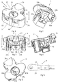
- Figures 1 and 2 illustrate a cable terminal protector 1.
- the cable terminal protector 1 comprises a first portion 3 and a second portion 5, which are snap-fitted together by means of cooperating snap fit units 6a, 6b, 6c, 6d located in the first portion 3 and second portion 5, respectively.
- Figures 3-5 illustrate the first portion 3 from three different perspectives.
- the cable terminal protector 1 is utilized to protect a cable terminal 7, see Figure 6 .
- the cable terminal 7 is attached to an end of a cable 9, which e.g. may be a battery cable of a vehicle.
- the cable terminal protector 1 and the cable terminal 7 together form a cable terminal protection arrangement according to the invention.
- the second portion 5 of the cable terminal protector 1 is provided with one or more bores, illustrated as a pair of bores 10a, 10b, which are intended to receive a respective pin located on an object, such as a vehicle body, to which the cable terminal protection arrangement is to be attached.
- the cable terminal 7 comprises a flat-shaped end piece 11 and a second portion 13 located next to the end piece 11, see Figure 6 .
- the second portion 13 is typically angled in relation to the end piece 11, e.g. by an angle in the range of 20°- 60°.
- the cable 9 is attached to the second portion 13 of the cable terminal 7, but there may also be other portions in between.
- the end piece 11 comprises a through-going hole 15 which is adapted for insertion of a fastening element, such as a screw or a bolt, which is utilized to attach the cable terminal 7 to the object, such as the vehicle body. This is further described below in conjunction with Figures 7a-7d .
- the end piece 11 has a first surface 17 and a second surface 19, which is opposite to the first surface 17.
- the cable terminal protector 1 comprises a housing 21, see Figure 1 , and a pair of suspension units 23a, 23b, see Figure 3 .
- the housing 21 gives an outer protection for the cable terminal 7 from the ambient environment.
- the cable terminal protector 1 is made of an electrically insulating material, e.g. plastics such as polypropylene, such that the cable terminal protector 1 electrically insulates the cable terminal 7.
- the housing 21 is formed by the outer walls of the first portion 3 and second portion 5.
- the housing 21 comprises a cable opening 25, see Figure 5 , located partly in the first portion 3 and partly in the second portion 5, which allows the cable 9 to enter into the cable terminal protector 1.
- the housing 21 further comprises a tool opening 27, see Figures 1 and 3 , located in the first portion 3, which makes it possible to use a tool, such as a socket, to attach the fastening element to the object, which is further described below in conjunction with Figures 7a-7d .
- the tool opening 27 typically faces in a direction being perpendicular or substantially perpendicular to a facing direction of the cable opening 25.
- the suspension units 23a, 23b shown in Figures 3 and 7a-d , are used to hold the end piece 11 of the cable terminal 7 in a desired position.
- Each suspension unit 23a, 23b comprises a respective arm 29a, 29b and a respective holding element 31 a, 31 b, with the arms 29a, 29b connecting the holding elements 31 a, 31 b to the housing 21.
- the two suspension units 23a, 23b are mirror images of each other, as e.g. seen in Figure 3 , wherein the two suspension units 23a, 23b are mirrored in a centre-plane C being perpendicular to both the tool opening 27 and to the cable opening 25.
- the holding elements 31 a, 31 b are shaped to hold the end piece 11. See Figure 7a for details of the suspension units 23a, 23b. Since two holding elements 31 a, 31 b are utilized, each of them will hold half of the end piece 11.
- Each holding element 31 a, 31 b comprises a proximal portion 33a, 33b facing the first surface 17 of the end piece 11 and a distal portion 35a, 35b facing the second surface 19 of the end piece 11.
- the proximal portion 33a, 33b and the distal portion 35a, 35b are connected by an intermediate portion 36a, 36b.
- the arm 29a, 29b is connected to the proximal portion 33a, 33b.
- the proximal portions 33a, 33b have through-going holes 37a, 37b, see Figure 5 .
- Each of the holes 37a, 37b is adapted to the shape of a half of the fastening element, such that the holes 37a, 37b together are adapted to allow insertion of the fastening element.
- the holes 37a, 37b are therefore to be aligned with the through-going hole 15 of the end piece 11.
- the distal portions 35a, 35b have through-going holes 39a, 39b, see Figure 2 , which are aligned with the holes 37a, 37b shown in Figure 5 of the proximal portions 33a, 33b.
- the holding element 31 a, 31 b may assume a first position, as illustrated in Figures 1-5, 7a and 7d and a second position, as illustrated in Figure 7c .
- a major portion of the second surface 19 of the end piece 11 is covered by the distal portions 35a, 35b of the holding element 31 a, 31 b, in the illustrated embodiment substantially all of the second surface 19.
- an interspace 40 between the two holding elements 31 a, 31 b in that position is less than 2 mm, preferably less than 1.5 mm.
- the cable terminal 7 is electrically insulated as seen from a bottom of the cable terminal protector 1, which can be seen in Figures 2-3 . See also Figure 7a .
- the holding elements 31 a, 31 b are biased to the first positions by the flexible properties and the shape of the arms 29a, 29b. Thereby the arms 29a, 29b function as springs pushing the two holding elements 31 a, 31 b towards each other.
- the arms 29a, 29b are shaped such that they are curved towards the centre-plane C being perpendicular to the tool opening 27 and to the cable opening 25. See Figure 3 . This shape helps to control the displacement of the holding elements 31 a, 31 b to their respective second positions, which is further described below in conjunction with Figures 7a-7d .
- the arms 29a, 29b are preferably resiliently flexible, such that they strive to go back to the first positions of the holding elements 31 a, 31 b.
- the arms 29a, 29b are capable of moving a plurality of times between the first and second positions, which may be useful if it is desired to release the attachment of the cable terminal 7 to the object, e.g. the vehicle body and to re-attach it.
- the housing 21 has an extension h in a first direction D 1 , which is perpendicular to a plane spanning the tool opening 27. See Figures 1 and 3 .
- the arms 29a, 29b are connected to the housing 21 at a distance d from the tool opening 27 as seen in the first direction D 1 .
- This distance d is less than a distance e to the holding element 31 a, 31 b, which is determined from the tool opening 27 to the geometrical centre of the holding element 31 a, 31b as seen in the first direction D 1 .
- the distance d is in the range of 0 ⁇ d ⁇ 0.5 h, more preferably 0 ⁇ d ⁇ 0.3 h, most preferably 0 ⁇ d ⁇ 0.1 h.
- the respective arm 29a, 29b comprises a bore 41 a, 41 b shown in Figure 5 " which faces the tool opening 27 and is aligned with the holes 37a, 37b of the proximal portions 33a, 33b and the holes 39a, 39b shown in Figure 2 of the distal portions 35a, 35b of the holding elements 31 a, 31 b.
- the bores 41 a, 41 b will help to guide the fastening element during attachment, which is further described below in conjunction with Figures 7a-7d .
- the cable terminal protector 1 may comprise an abutment 43, which in the illustrated embodiment is formed as an integral unit with the first portion 23, see Figure 4 .
- the abutment 43 supports the second portion 13 of the cable terminal 7. This helps to keep a fixed and secure attachment of the cable 9 to the cable terminal protector 1.
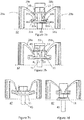
- Figures 7a-7d illustrate the two suspension units 23a, 23b and the fastening element 45 when attaching the cable terminal arrangement comprising the cable terminal protector 1 and the cable terminal 7 to an object 47, such as a vehicle body, indicated by a dashed line in Figures 7a-7d .
- the fastening element 45 is a flanged bolt. It extends in an axial direction A and comprises a stem 51 with a first radius R 1 , which is adapted to fit inside the hole 15 of the end piece 11.
- the fastening element 45 also has a second radius R 2 , which is larger than the first radius R 1 .
- the second radius R 2 is given by a radius of a flange 49 of the fastening element 45. See Figure 7b for details of the fastening element 45.
- the cable terminal arrangement comprising the cable terminal protector 1 and the cable terminal 7 is positioned on the object with the tool opening 27 facing away from the object 47. Thereby, the above-mentioned bores 10a, 10b of the second portion 5 of the cable terminal protector 1 are placed over corresponding pins located on the object (not illustrated).
- the fastening element 45 is inserted through the tool opening 27 into the through-going hole 15 of the end piece 11, in the illustrated embodiment by screwing of the flanged bolt 45. As long as the flange 49 is above the arms 29a, 29b, the holding elements 31 a, 31 b are in the first positions, in which they electrically insulate the cable terminal 7. See Figure 7a .
- the fastening element 45 may be inserted with the help of a socket 53 configured to cooperate with the fastening element 45.
- the flange 49 starts acting on the arms 29a, 29b by pushing the arms 29a, 29b to the side, see Figure 7b .
- the holding elements 31 a, 31 b are displaced towards the second positions.
- the displacement motion is governed by the curved shape of the arms 29a, 29b. With the illustrated curvature, there is a faster sideways displacement at the beginning of the displacement towards the second positions than at the end of the displacement.
- the holding elements 31 a, 31 b reach the second position, see Figure 7c . They are then so far spaced apart that the end piece 11 can pass between the holding elements 31 a, 31 b. The end piece 11 therefore leaves the holding elements 31 a, 31 b and instead moves together with the fastening element 45 until the fastening element 45 is attached to the object 47. Then the end piece 11 is in electrical contact with the object 47. See Figure 7d .
- the cable terminal protector 1 is held in position by means of the pins located on the object cooperating with the bores 10a, 10b of the second portion 5, not illustrated.
- the holding elements 31 a, 31 b may be pushed to the second position by the socket 53, such that the fastening element 45 and the end piece 11 can pass upwards between the holding elements 31 a, 31 b.
Landscapes
- Engineering & Computer Science (AREA)
- Manufacturing & Machinery (AREA)
- Installation Of Indoor Wiring (AREA)
Abstract
Description
- The present disclosure relates to a cable terminal protection arrangement comprising a cable terminal and a cable terminal protector adapted to protect the cable terminal. The disclosure also relates to a kit comprising the cable terminal protection arrangement and a fastening element. The disclosure further relates to a method of attaching the cable terminal protection arrangement to an object, e.g. a vehicle body.
- When manufacturing a vehicle, such as a car, a cable is connected to a battery of the vehicle. It is thereafter desirable to protect the other end of the cable, usually ending in a cable terminal, from uncontrolled grounding, e.g. against the vehicle body. Therefore a cable terminal protector may be used to enclose the cable terminal in order to protect it. It may also be interesting to protect other cable terminals in a corresponding way.
- A commonly used cable terminal protector partly surrounds the cable terminal during factory handling and logistics. Further the cable terminal protector is configured such that the cable terminal is easy to attach when grounding is desired, i.e. for intentional grounding. However, there is still a risk of uncontrolled grounding, since the cable terminal is at least partly exposed to the environment.
-
Patent document US 5,191,172 discloses a cable terminal protector, comprising two generally rectangular main members joined at one end by a hinge, which gives good protection from unintentional grounding. However, in order to connect the cable terminal to the vehicle body, the cable terminal protector ofUS 5,191,172 has to be removed manually, resulting in an extra manufacturing step, which costs time and effort. - It is thus desirable to provide a cable terminal protector which gives good protection from unintentional grounding during factory handling and logistics and yet makes it easy to connect the cable terminal to an object, such as a vehicle body, for intentional grounding.
- In addition, it is desirable that the cable terminal protector is able to ascertain a stable position of the cable terminal in the cable terminal protector, such that a cable terminal protection arrangement comprising the cable terminal and the cable terminal protector can withstand external forces applied to the cable terminal protector or to the cable without being deformed or broken and such that the cable terminal is still protected.
- It is also desirable that the cable terminal is connected to the object in a clean connection for the intentional grounding, i.e. without a potential risk that parts of the cable terminal protector end up in between the cable terminal and the object, thus at least partly destroying the electrical connection.
- The object of the present disclosure is to overcome or ameliorate at least one of the disadvantages of the prior art, or to provide a useful alternative.
- The object above may be achieved by the subject-matter of
claim 1. Embodiments are set forth in the appended dependent claims, in the following description and in the drawings. - Thus, the present invention relates to a cable terminal protection arrangement comprising a cable terminal and a cable terminal protector adapted to protect the cable terminal. The cable terminal is attachable or attached to an end of a cable, e.g. a battery cable. The cable terminal comprises a flat-shaped end piece with a first surface and a second surface being opposite to the first surface. The end piece comprises a through-going hole adapted for insertion of a fastening element, such as a screw or bolt. The cable terminal protector comprises a housing with a cable opening for receiving the cable and a tool opening. The first surface of the end piece is adapted to face the tool opening and the second surface is adapted to face away from the tool opening. The cable terminal protection arrangement further comprises a suspension unit located within the housing. The suspension unit comprises a holding element for holding the end piece and an arm connecting the holding element to the housing. The holding element is displaceable in relation to the housing from a first position to a second position, wherein, in the first position, a major portion of the second surface of the end piece is covered by the holding element, and in the second position, the end piece is outside the holding element.
- The cable terminal protector is made of an electrically insulating material, e.g. plastics such as polypropylene, such that the cable terminal protector is able to electrically insulate the cable terminal, as long as the cable terminal is covered. The housing gives an outer protection for the cable terminal from the ambient environment.
- The fastening element is to be used for connecting the cable terminal to the object, i.e. for intentional grounding. It may be a screw or a bolt, e.g. a flanged screw or bolt.
- The first position of the holding element is used during factory handling and logistics of the cable terminal protection arrangement. The second position is used when the intentional grounding is to be obtained, i.e. when the cable terminal is to be attached to the object, e.g. the vehicle body.
- In the first position of the holding element, a major portion of the second surface of the end piece is covered by the holding element. This provides good protection from unintentional grounding during factory handling and logistics. At least 70% of the second surface of the end piece may be covered by the holding element, preferably at least 80%, more preferably at least 90%, most preferably at least 95%.
- The suspension unit ascertains a stable position of the cable terminal in the cable terminal protector when the holding element is in the first position, by holding the end piece in a pre-determined position. Thereby a cable terminal protection arrangement comprising the cable terminal and the cable terminal protector can withstand external forces applied to the cable terminal protector or to the cable. In particular, the risk that the cable terminal would fall out of the cable terminal protector is avoided or at least reduced as compared to prior art.
- In the second position of the holding element, the end piece of the cable terminal can pass the holding element. Thereby the cable terminal can be connected to the object to obtain the intentional grounding. Since the holding element is displaced out of the way, the risk that parts of the cable terminal protector would end up in between the cable terminal and the object, thus at least partly destroying the electrical connection, is avoided or at least reduced as compared to prior art.
- When moving from the first position to the second position, the holding element is displaced in relation to the housing. Preferably this displacement occurs mainly in a plane being parallel to the tool opening and thus typically being perpendicular to the cable opening, such that the holding element is moved to the side as seen in relation to an axial direction of the fastening element.
- Preferably also the holding element comprises a through-going hole adapted for insertion of the fastening element. The hole is preferably shaped after the fastening element. Hence, the hole of the holding element may mimic the whole or a portion of the through-going hole of the end piece.
- The tool opening allows a tool, such as a socket, to enter the housing, such that the end piece can be attached to an object, e.g. the vehicle body, by means of the tool operating on the fastening element, e.g. screwing the fastening element into the object by means of a socket adapted to cooperate with the fastening element. The holding element is aligned with the tool opening, such that there is access to the cable terminal with the fastening element. Preferably, the tool opening faces in a direction being perpendicular to, or substantially perpendicular to, a facing direction of the cable opening.
- The holding element is preferably shaped to hold the end piece in a stable position in the housing when the holding element is in its first position. The holding element may thus comprise a proximal portion facing the first surface of the end piece and a distal portion facing the second surface of the end piece, thus being parallel to the proximal portion. The proximal portion and the distal portion may be connected by an intermediate portion corresponding to the thickness of the end piece.
- As mentioned above, the holding element is displaceable from the first position to the second position. In addition, the holding element may be displaceable from the second position back to the first position. Thereby the holding element can move back to the first position when the end piece has passed the holding element, e.g. to be connected to the object. Further, it is preferred that the holding element is able to move a plurality of times between the first and second positions, which may be useful if it is desired to release the attachment of the cable terminal to the object and to re-attach it again.
- The holding element may be biased towards the first position, e.g. spring-biased. The arm of the suspension unit may be flexible, preferably resiliently flexible. Thereby the arm has a spring function, which may bias the holding element towards the first position.
- The holding elements may be biased towards the first positions by the flexible properties and/or the shape of the arm. Thereby, the arm may function as a spring pushing the holding element towards the first position. The arm may be shaped such that it is curved towards a centre-plane being perpendicular to the tool opening and to the cable opening. This shape helps to control the movement of the displacement of the holding elements to the second position. The arm is preferably resiliently flexible, such that it strives to go back to the first position of the holding element.
- The housing has an extension h in a first direction D1, which is perpendicular to a plane spanning the tool opening. The arm may be connected to the housing at a distance d from the tool opening as seen in the first direction D1, which distance d is less than a distance e to the holding element as seen in the first direction D1. Preferably the distance d is in the range of 0 ≤ d < 0.5 h, more preferably 0 ≤ d < 0.3 h, most preferably 0 ≤ d < 0.1 h. It has been found beneficial that the arms are connected to a top portion of the housing, i.e. the portion of the housing comprising the tool opening.
- The arm may comprise a bore facing the tool opening. The bore may help to guide the fastening element during insertion. The bore is preferably aligned with the through-going hole of the end piece and/or with the through-going hole of the holding element, such that the fastening element may be inserted through the bore of the arm and the respective through-going holes.
- The cable terminal protection arrangement may comprise an additional suspension unit comprising an additional holding element and an additional arm, preferably the additional suspension unit being a mirror image of the suspension unit, e.g. as seen in the centre-plane being perpendicular to the tool opening and to the cable opening of the housing. If using two holding elements located opposite to each other and being each other's mirror image, it has been found beneficial that an interspace between the two holding elements is less than 2 mm, preferably less than 1.5 mm at the portion of the holding element covering the second surface of the end piece.
- The housing may comprise, or be constituted by, a first portion and a second portion, the first portion being adapted to face the first surface of the end piece and the second portion being adapted to face the second surface of the end piece, the first portion comprising the tool opening. Preferably, the first and the second portions are snap-fittable to each other.
- The usage of a first portion and a second portion of the housing makes it easy to fit the cable terminal protector around the cable terminal. The first portion may form a top portion and the second portion may form a bottom portion of the cable terminal protector. The suspension unit may be comprised in the first portion, either as an integral part or as a separate component attached to the first portion. In that case, the cable terminal may first be inserted in the holding element and then the second portion may be snap-fitted to the first portion from either side of the cable terminal to form the cable terminal protection arrangement described herein. The cable opening may in that case be located partly in the first and partly in the second portion.
- The cable terminal may comprise a second portion located adjacent to the end piece. In that case, the cable terminal protection arrangement may comprise an abutment located spaced apart from the suspension unit, such that the second portion of the cable terminal is adapted to abut the abutment. The abutment may thus support the second portion of the cable terminal. This helps to keep a fix and secure attachment of the cable to the cable terminal protector. The abutment may be a separate component located inside the housing. However, it is preferred that the abutment is integral with the housing, e.g. integral with the first portion.
- The present invention further relates to a kit comprising the cable terminal protection arrangement as described herein and a fastening element, e.g. a screw or a bolt. The fastening element has at first portion, e.g. a stem, with a first radius and a second portion with a second radius being larger than the first radius, wherein the first radius is configured to pass through the through-going hole of the end piece of the cable terminal and the second radius is configured to cooperate with the arm of the suspension unit during the displacement of the holding element from the first position to the second position.
- The fastening element extends in an axial direction. The fastening element is inserted by being attached to the object, e.g. the vehicle body. If the fastening element is threaded, e.g. being a screw or a bolt, the fastening element is inserted by screwing. During insertion of the fastening element, the portion of the fastening element having the second radius pushes the holding element to the second position by acting on the arm of the suspension unit, preferably by gradually pushing the arm. The fastening element may be inserted with the help of a tool, e.g. a socket, configured to cooperate with the fastening element, e.g. being shaped to grip a head of the screw or bolt.
- The fastening element may be a flanged screw or a flanged bolt. In that case, the first radius is a radius of the stem of the fastening element and the second radius is a radius of a flange of the fastening element.
- The present invention also relates to a method of attaching a cable terminal protection arrangement as described herein to an object, e.g. a vehicle body. The method comprises:
- a) Providing a fastening element, e.g. a screw or a bolt.
- b) Positioning the cable terminal protection arrangement on the object with the tool opening facing away from the object.
- c) Inserting the fastening object through the tool opening and through the through-going hole of the end piece, which is held by the holding element being in the first position.
- d) Displacing the holding element to the second position by means of further insertion of the fastening element.
- e) Attaching the end piece to the object by means of further insertion of the fastening element.
- Step d) may be performed by the fastening element acting on the arm of the suspension unit, thereby displacing the holding element to the second position.
- If it for some reason is desirable to release the end piece from the object, the holding elements may be pushed to the second position by the socket, such that the fastening element and the end piece can be displaced to a position in which the holding element once again holds the end piece. If two holding elements are provided, the fastening element and the end piece may then pass between the holding elements.
- The present invention will hereinafter be further explained by means of non-limiting examples with reference to the appended drawings wherein:
-
Fig. 1 is a perspective view of a cable terminal protector. -
Fig. 2 is another perspective view of the cable terminal protector. -
Fig. 3 is a perspective view of a first portion of the cable terminal protector. -
Fig. 4 is another perspective view of the first portion of the cable terminal protector. -
Fig. 5 is yet another perspective view of the first portion of the cable terminal protector. -
Fig. 6 is a top view of a cable terminal. -
Fig. 7a-7d illustrate two suspension units of the cable terminal protector and a fastening element when attaching the cable terminal to an object. - It should be noted that the appended drawings are schematic and that individual components are not necessarily drawn to scale and that the dimensions of some features of the present invention may have been exaggerated for the sake of clarity.
- The invention will, in the following, be exemplified by embodiments. It should however be realized that the embodiments are included in order to explain principles of the invention and not to limit the scope of the invention, as defined by the appended claims. A feature from one embodiment may be combined with one or more features of any other embodiment.
-
Figures 1 and 2 illustrate acable terminal protector 1. Thecable terminal protector 1 comprises afirst portion 3 and asecond portion 5, which are snap-fitted together by means of cooperating snapfit units first portion 3 andsecond portion 5, respectively.Figures 3-5 illustrate thefirst portion 3 from three different perspectives. Thecable terminal protector 1 is utilized to protect acable terminal 7, seeFigure 6 . Thecable terminal 7 is attached to an end of acable 9, which e.g. may be a battery cable of a vehicle. Thecable terminal protector 1 and thecable terminal 7 together form a cable terminal protection arrangement according to the invention. - The
second portion 5 of thecable terminal protector 1 is provided with one or more bores, illustrated as a pair ofbores - The
cable terminal 7 comprises a flat-shapedend piece 11 and asecond portion 13 located next to theend piece 11, seeFigure 6 . Thesecond portion 13 is typically angled in relation to theend piece 11, e.g. by an angle in the range of 20°- 60°. In the illustrated embodiment, thecable 9 is attached to thesecond portion 13 of thecable terminal 7, but there may also be other portions in between. Theend piece 11 comprises a through-goinghole 15 which is adapted for insertion of a fastening element, such as a screw or a bolt, which is utilized to attach thecable terminal 7 to the object, such as the vehicle body. This is further described below in conjunction withFigures 7a-7d . Theend piece 11 has afirst surface 17 and asecond surface 19, which is opposite to thefirst surface 17. - The
cable terminal protector 1 comprises ahousing 21, seeFigure 1 , and a pair ofsuspension units Figure 3 . Thehousing 21 gives an outer protection for thecable terminal 7 from the ambient environment. Thecable terminal protector 1 is made of an electrically insulating material, e.g. plastics such as polypropylene, such that thecable terminal protector 1 electrically insulates thecable terminal 7. In the illustrated embodiment thehousing 21 is formed by the outer walls of thefirst portion 3 andsecond portion 5. Thehousing 21 comprises acable opening 25, seeFigure 5 , located partly in thefirst portion 3 and partly in thesecond portion 5, which allows thecable 9 to enter into thecable terminal protector 1. Thehousing 21 further comprises atool opening 27, seeFigures 1 and 3 , located in thefirst portion 3, which makes it possible to use a tool, such as a socket, to attach the fastening element to the object, which is further described below in conjunction withFigures 7a-7d . Thetool opening 27 typically faces in a direction being perpendicular or substantially perpendicular to a facing direction of thecable opening 25. When thecable terminal 7 is positioned in thecable terminal protector 1, thefirst surface 17 of theend piece 11 faces thetool opening 27. - The
suspension units Figures 3 and 7a-d , are used to hold theend piece 11 of thecable terminal 7 in a desired position. Eachsuspension unit respective arm respective holding element arms elements housing 21. The twosuspension units Figure 3 , wherein the twosuspension units tool opening 27 and to thecable opening 25. - The holding
elements end piece 11. SeeFigure 7a for details of thesuspension units elements end piece 11. Each holdingelement proximal portion first surface 17 of theend piece 11 and adistal portion second surface 19 of theend piece 11. Theproximal portion distal portion intermediate portion 36a, 36b. Thearm proximal portion proximal portions holes Figure 5 . Each of theholes holes holes hole 15 of theend piece 11. Correspondingly, thedistal portions holes Figure 2 , which are aligned with theholes Figure 5 of theproximal portions - The holding
element Figures 1-5, 7a and 7d and a second position, as illustrated inFigure 7c . In the first position, a major portion of thesecond surface 19 of theend piece 11 is covered by thedistal portions element second surface 19. It has been found beneficial that aninterspace 40 between the two holdingelements cable terminal 7 is electrically insulated as seen from a bottom of thecable terminal protector 1, which can be seen inFigures 2-3 . See alsoFigure 7a . - The holding
elements arms arms elements arms tool opening 27 and to thecable opening 25. SeeFigure 3 . This shape helps to control the displacement of the holdingelements Figures 7a-7d . Thearms elements arms cable terminal 7 to the object, e.g. the vehicle body and to re-attach it. - The
housing 21 has an extension h in a first direction D1, which is perpendicular to a plane spanning thetool opening 27. SeeFigures 1 and 3 . Thearms housing 21 at a distance d from thetool opening 27 as seen in the first direction D1. This distance d is less than a distance e to the holdingelement tool opening 27 to the geometrical centre of the holdingelement - The
respective arm bore Figure 5 " which faces thetool opening 27 and is aligned with theholes proximal portions holes Figure 2 of thedistal portions elements bores Figures 7a-7d . - As an option, disclosed in the illustrated embodiment, the
cable terminal protector 1 may comprise anabutment 43, which in the illustrated embodiment is formed as an integral unit with the first portion 23, seeFigure 4 . Theabutment 43 supports thesecond portion 13 of thecable terminal 7. This helps to keep a fixed and secure attachment of thecable 9 to thecable terminal protector 1. -
Figures 7a-7d illustrate the twosuspension units fastening element 45 when attaching the cable terminal arrangement comprising thecable terminal protector 1 and thecable terminal 7 to anobject 47, such as a vehicle body, indicated by a dashed line inFigures 7a-7d . - First the
fastening element 45 is provided. In the illustrated embodiment, thefastening element 45 is a flanged bolt. It extends in an axial direction A and comprises astem 51 with a first radius R1, which is adapted to fit inside thehole 15 of theend piece 11. Thefastening element 45 also has a second radius R2, which is larger than the first radius R1. In the illustrated embodiment, the second radius R2 is given by a radius of aflange 49 of thefastening element 45. SeeFigure 7b for details of thefastening element 45. - The cable terminal arrangement comprising the
cable terminal protector 1 and thecable terminal 7 is positioned on the object with thetool opening 27 facing away from theobject 47. Thereby, the above-mentionedbores second portion 5 of thecable terminal protector 1 are placed over corresponding pins located on the object (not illustrated). - The
fastening element 45 is inserted through thetool opening 27 into the through-goinghole 15 of theend piece 11, in the illustrated embodiment by screwing of theflanged bolt 45. As long as theflange 49 is above thearms elements cable terminal 7. SeeFigure 7a . Thefastening element 45 may be inserted with the help of asocket 53 configured to cooperate with thefastening element 45. - Once the
flange 49 reaches thearms fastening element 45, theflange 49 starts acting on thearms arms Figure 7b . Thereby, the holdingelements arms - Eventually, the holding
elements Figure 7c . They are then so far spaced apart that theend piece 11 can pass between the holdingelements end piece 11 therefore leaves the holdingelements fastening element 45 until thefastening element 45 is attached to theobject 47. Then theend piece 11 is in electrical contact with theobject 47. SeeFigure 7d . Thecable terminal protector 1 is held in position by means of the pins located on the object cooperating with thebores second portion 5, not illustrated. - If it for some reason is desirable to release the
end piece 11 from theobject 47, the holdingelements socket 53, such that thefastening element 45 and theend piece 11 can pass upwards between the holdingelements - Further modifications of the invention within the scope of the appended claims are feasible. As such, the present invention should not be considered as limited by the embodiments and figures described herein. Rather, the full scope of the invention should be determined by the appended claims, with reference to the description and drawings.
Claims (15)
- A cable terminal protection arrangement comprising a cable terminal (7) and a cable terminal protector (1) adapted to protect said cable terminal (7),
said cable terminal (7) being attachable or attached to an end of a cable (9), e.g. a battery cable,
said cable terminal (7) comprising a flat-shaped end piece (11) with a first surface (17) and a second surface (19), being opposite to said first surface (17), said end piece (11) comprising a through-going hole (15) adapted for insertion of a fastening element (45),
said cable terminal protector (1) comprising a housing (21) having a cable opening (25) for receiving said cable (9) and a tool opening (27),
said first surface (17) of said end piece (11) being adapted to face said tool opening (25) and said second surface (19) being adapted to face away from said tool opening (27),
characterized in that
said cable terminal protection arrangement further comprises a suspension unit (23a, 23b) located within said housing (21),
said suspension unit (23a, 23b) comprising a holding element (31 a, 31 b) for holding said end piece (11) and an arm (29a, 29b) connecting said holding element (31 a, 31 b) to said housing (21),
said holding element (31 a, 31 b) being displaceable in relation to said housing (21) from a first position to a second position,
wherein, in said first position, a major portion of said second surface (19) of said end piece (11) is covered by said holding element (31 a, 31 b), and, in said second position, said end piece (11) is outside said holding element (31 a, 31 b). - The cable terminal protection arrangement according to claim 1, wherein in said first position at least 70% of said second surface (19) of said end piece (11) is covered by said holding element (31 a, 31 b), preferably at least 80%, more preferably at least 90%, most preferably at least 95%.
- The cable terminal protection arrangement according to any one of the preceding claims, wherein said holding element (31 a, 31 b) has a through-going hole (37a, 37b; 39a, 39b) adapted for insertion of said fastening element (45).
- The cable terminal protection arrangement according to any one of the preceding claims, wherein said holding element (31 a, 31 b) is biased towards said first position, e.g. spring-biased.
- The cable terminal protection arrangement according to any one of the preceding claims, wherein said arm (29a, 29b) of said suspension unit (23a, 23b) is flexible, preferably resiliently flexible.
- The cable terminal protection arrangement according to any one of the preceding claims, wherein said arm (29a, 29b) has a curved shape, preferably said arm (29a, 29b) being curved in a direction towards a centre-plane (C) being perpendicular to said tool opening (27) and to said cable opening (25) of said housing (21).
- The cable terminal protection arrangement according to any one of the preceding claims, in which said housing (21) has an extension h in a first direction (D1), which is perpendicular to a plane spanning said tool opening (27), said arm (29a, 29b) being connected to said housing (21) at a distance d from said tool opening (27), as seen in said first direction (D1), said distance d being less than a distance e to said holding element (31 a, 31 b) as seen in said first direction (D1), preferably said distance d being in the range of 0 ≤ d < 0.5 h, more preferably 0 ≤ d < 0.3 h, most preferably 0 ≤ d < 0.1 h.
- The cable terminal protection arrangement according to any one of the preceding claims, wherein said arm (29a, 29b) comprises a bore (41 a, 41 b) facing said tool opening (27).
- The cable terminal protection arrangement according to any one of the preceding claims, comprising an additional suspension unit (23b) comprising an additional holding element (31 b) and an additional arm (29b), preferably said additional suspension unit (23b) being a mirror image of said suspension unit (23a), e.g. as seen in said centre-plane (C) being perpendicular to said tool opening (27) and to said cable opening (25) of said housing (21).
- The cable terminal protection arrangement according to any one of the preceding claims, wherein said housing (21) comprises, or is constituted by, a first portion (3) and a second portion (5), said first portion (3) being adapted to face said first surface (17) of said end piece (11) and said second portion (5) being adapted to face said second surface (19) of said end piece (11), said first portion (3) comprising said tool opening (27), preferably said first and said second portions (3, 5) being snap-fittable to each other.
- The cable terminal protection arrangement according to any one of the preceding claims, when said cable terminal (7) comprises a second portion (13) located adjacent to said end piece (11), wherein said cable terminal protection arrangement comprises an abutment (43) located spaced apart from said suspension unit (23a, 23b), such that said second portion (13) of said cable terminal (7) is adapted to abut said abutment (43).
- A kit comprising a cable terminal protection arrangement according to any one of the preceding claims and a fastening element (45), e.g. a screw or a bolt, said fastening element (45) having at first portion with a first radius (R1) and a second portion with a second radius (R2) being larger than said first radius (R1), wherein said first radius (R1) is configured to pass through said through-going hole (15) of said end piece (11) of said cable terminal (7) and said second radius (R2) is configured to cooperate with said arm (29a, 29b) of said suspension unit (23a, 23b) during said displacement of said holding element (31 a, 31 b) from said first position to said second position.
- The kit according to claim 12, wherein said fastening element (45) is a flanged screw or a flanged bolt and said first radius (R1) is a radius of a stem (51) of said fastening element (45) and said second radius (R2) is a radius of a flange (49) of said fastening element (45).
- A method of attaching a cable terminal protection arrangement according to any one of claims 1-11 to an object (47), e.g. a vehicle body, said method comprisinga) providing a fastening element (45), e.g. a screw or a bolt,b) positioning said cable terminal protection arrangement on said object (47) with said tool opening (27) facing away from said object (47),c) inserting said fastening object (47) through said tool opening (27) and through said through-going hole (15) of said end piece (11), which is held by said holding element (31 a, 31 b) being in said first position,d) displacing said holding element (31 a, 31 b) to said second position by means of further insertion of said fastening element (31 a, 31b),e) attaching said end piece (11) to said object (47) by means of further insertion of said fastening element (45).
- The method according to claim 14, wherein said step d) is performed by said fastening element (45) acting on said arm (29a, 29b) of said suspension unit (23a, 23b), thereby displacing said holding element (45) to the second position.
Priority Applications (3)
| Application Number | Priority Date | Filing Date | Title |
|---|---|---|---|
| EP17020222.0A EP3407445B1 (en) | 2017-05-22 | 2017-05-22 | Cable terminal protection arrangement |
| CN201810459051.9A CN108933422B (en) | 2017-05-22 | 2018-05-15 | Cable terminal protection device |
| US15/979,996 US10218092B2 (en) | 2017-05-22 | 2018-05-15 | Cable terminal protection arrangement |
Applications Claiming Priority (1)
| Application Number | Priority Date | Filing Date | Title |
|---|---|---|---|
| EP17020222.0A EP3407445B1 (en) | 2017-05-22 | 2017-05-22 | Cable terminal protection arrangement |
Publications (2)
| Publication Number | Publication Date |
|---|---|
| EP3407445A1 true EP3407445A1 (en) | 2018-11-28 |
| EP3407445B1 EP3407445B1 (en) | 2022-01-26 |
Family
ID=58994816
Family Applications (1)
| Application Number | Title | Priority Date | Filing Date |
|---|---|---|---|
| EP17020222.0A Active EP3407445B1 (en) | 2017-05-22 | 2017-05-22 | Cable terminal protection arrangement |
Country Status (3)
| Country | Link |
|---|---|
| US (1) | US10218092B2 (en) |
| EP (1) | EP3407445B1 (en) |
| CN (1) | CN108933422B (en) |
Cited By (1)
| Publication number | Priority date | Publication date | Assignee | Title |
|---|---|---|---|---|
| DE102023104652A1 (en) * | 2023-02-24 | 2024-08-29 | Te Connectivity Solutions Gmbh | Contact protection cover, connection part and module connector |
Families Citing this family (4)
| Publication number | Priority date | Publication date | Assignee | Title |
|---|---|---|---|---|
| JP2021150150A (en) * | 2020-03-18 | 2021-09-27 | 矢崎総業株式会社 | Terminal cap |
| CN111370880A (en) * | 2020-03-31 | 2020-07-03 | 浙江人禾电子有限公司 | A copper bar with an insulating sheath |
| CN113972512A (en) | 2020-07-23 | 2022-01-25 | 哈廷电子有限公司及两合公司 | Protective cover for a high-current plug connector |
| FR3167770A1 (en) * | 2024-10-17 | 2026-04-24 | Plastic Omnium Clean Energy Systems Research | Electrical connection device for battery system |
Citations (5)
| Publication number | Priority date | Publication date | Assignee | Title |
|---|---|---|---|---|
| US5191172A (en) | 1991-11-07 | 1993-03-02 | Garganese Richard S | Cable terminal protector |
| EP0895305A1 (en) * | 1997-07-30 | 1999-02-03 | Sumitomo Wiring Systems, Ltd. | A joint device for automotive wiring harness |
| US20060239794A1 (en) * | 2004-11-12 | 2006-10-26 | Lisa Draxlmaier Gmbh | Arrangement for mounting a lug on a screw |
| EP2063492A2 (en) * | 2007-11-21 | 2009-05-27 | Newfrey LLC | Contact-making unit, attachment method and screwing tool for acrrying out the method |
| US20110053434A1 (en) * | 2008-02-13 | 2011-03-03 | Hans-Peter Seng | Retaining device for cable lugs |
Family Cites Families (12)
| Publication number | Priority date | Publication date | Assignee | Title |
|---|---|---|---|---|
| US4883431A (en) * | 1986-09-26 | 1989-11-28 | Raychem Corporation | Gel-filled cap member |
| DE29616631U1 (en) * | 1996-09-24 | 1996-11-14 | Emhart Inc., Newark, Del. | Fastening arrangement |
| FR2774221B1 (en) * | 1998-01-27 | 2000-04-14 | Legrand France | HOUSING TO BE RECESSED IN ANY WALL, ESPECIALLY FOR AN ELECTRICAL APPARATUS |
| US6079923A (en) * | 1998-04-23 | 2000-06-27 | Penn Engineering & Manufacturing Corp. | Hybrid panel fastener |
| JPH11339906A (en) * | 1998-05-22 | 1999-12-10 | Amp Japan Ltd | Substrate mount connector |
| JP2001160432A (en) * | 1999-12-02 | 2001-06-12 | Sumitomo Wiring Syst Ltd | Terminal protection cap |
| US6475020B1 (en) * | 2001-12-20 | 2002-11-05 | Hon Hai Precision Ind. Co., Ltd. | IDC connector assembly |
| DE102006056065B4 (en) * | 2006-11-20 | 2018-08-09 | Newfrey Llc | Pre-assembled contacting unit and mounting arrangement |
| US7946895B2 (en) * | 2008-04-21 | 2011-05-24 | Newfrey Llc | Internally threaded nut with a collar held captive in a nut holding section |
| JP5501018B2 (en) * | 2010-02-15 | 2014-05-21 | 矢崎総業株式会社 | Anti-tightening protection cap for fusible links attached directly to the battery |
| CN203300879U (en) * | 2013-05-17 | 2013-11-20 | 苏州华旃航天电器有限公司 | Power terminal protective cover |
| CN203862468U (en) * | 2014-04-28 | 2014-10-08 | 吉林大学 | Piezoelectric-drive-type spraying-direction flexible adjusting device |
-
2017
- 2017-05-22 EP EP17020222.0A patent/EP3407445B1/en active Active
-
2018
- 2018-05-15 CN CN201810459051.9A patent/CN108933422B/en active Active
- 2018-05-15 US US15/979,996 patent/US10218092B2/en active Active
Patent Citations (5)
| Publication number | Priority date | Publication date | Assignee | Title |
|---|---|---|---|---|
| US5191172A (en) | 1991-11-07 | 1993-03-02 | Garganese Richard S | Cable terminal protector |
| EP0895305A1 (en) * | 1997-07-30 | 1999-02-03 | Sumitomo Wiring Systems, Ltd. | A joint device for automotive wiring harness |
| US20060239794A1 (en) * | 2004-11-12 | 2006-10-26 | Lisa Draxlmaier Gmbh | Arrangement for mounting a lug on a screw |
| EP2063492A2 (en) * | 2007-11-21 | 2009-05-27 | Newfrey LLC | Contact-making unit, attachment method and screwing tool for acrrying out the method |
| US20110053434A1 (en) * | 2008-02-13 | 2011-03-03 | Hans-Peter Seng | Retaining device for cable lugs |
Cited By (3)
| Publication number | Priority date | Publication date | Assignee | Title |
|---|---|---|---|---|
| DE102023104652A1 (en) * | 2023-02-24 | 2024-08-29 | Te Connectivity Solutions Gmbh | Contact protection cover, connection part and module connector |
| JP2024120874A (en) * | 2023-02-24 | 2024-09-05 | ティーイー コネクティビティ ソリューソンズ ゲーエムベーハー | Touch protection covers, connecting parts and module connectors |
| EP4451476A1 (en) * | 2023-02-24 | 2024-10-23 | TE Connectivity Solutions GmbH | Touch protection cover, connection part and module connector |
Also Published As
| Publication number | Publication date |
|---|---|
| US20180337466A1 (en) | 2018-11-22 |
| US10218092B2 (en) | 2019-02-26 |
| CN108933422B (en) | 2020-05-05 |
| CN108933422A (en) | 2018-12-04 |
| EP3407445B1 (en) | 2022-01-26 |
Similar Documents
| Publication | Publication Date | Title |
|---|---|---|
| US10218092B2 (en) | Cable terminal protection arrangement | |
| CN102074843B (en) | Plug-in type connector housing with angled strain relief element | |
| KR101569266B1 (en) | Receptacle contact | |
| EP2156519B1 (en) | Plug connector housing with a fixing for an electric contact element and a cable | |
| US8366463B2 (en) | Safety structure for electric receptacles and power strips | |
| CN104253340B (en) | Electrical connector with integrated movable terminal stabilizer | |
| ES2747974T3 (en) | Electric connector | |
| KR20160098357A (en) | Holding frame for a plug-type connector | |
| US20140227913A1 (en) | Electric Connector with a Lock to Retain a Terminal Within a Housing | |
| US9070999B2 (en) | Electric connector and terminal used therefor | |
| TWI550964B (en) | Connector | |
| US8790142B2 (en) | Plug-type connector | |
| AU2007349106B2 (en) | Electric connector with a dust cover | |
| CN104981946B (en) | Electrical components with electrical connections | |
| US9231338B2 (en) | Variable wire strain relief connector | |
| US20160141131A1 (en) | Connection structure of electronic component and terminal metal fittings | |
| JP6339698B2 (en) | Connectors and connector systems | |
| CN112864764B (en) | Device for attaching an insulator sleeve to an electrical conductor | |
| JP7051706B2 (en) | Contact elements for optical connectors and optical connectors | |
| CN116137397A (en) | Electrical terminal, terminal assembly, connector assembly and method of manufacturing the terminal assembly | |
| US7540791B1 (en) | Universal battery terminal adaptor | |
| US20200127390A1 (en) | Terminal and electric wire with the same | |
| US9397454B2 (en) | Electrical connecting device, connector kit, and method of electrically connecting two apparatus | |
| EP3959782B1 (en) | Forklift connector lockout | |
| JP2000147322A (en) | Optical connector plug and optical communication module |
Legal Events
| Date | Code | Title | Description |
|---|---|---|---|
| PUAI | Public reference made under article 153(3) epc to a published international application that has entered the european phase |
Free format text: ORIGINAL CODE: 0009012 |
|
| STAA | Information on the status of an ep patent application or granted ep patent |
Free format text: STATUS: THE APPLICATION HAS BEEN PUBLISHED |
|
| AK | Designated contracting states |
Kind code of ref document: A1 Designated state(s): AL AT BE BG CH CY CZ DE DK EE ES FI FR GB GR HR HU IE IS IT LI LT LU LV MC MK MT NL NO PL PT RO RS SE SI SK SM TR |
|
| AX | Request for extension of the european patent |
Extension state: BA ME |
|
| STAA | Information on the status of an ep patent application or granted ep patent |
Free format text: STATUS: REQUEST FOR EXAMINATION WAS MADE |
|
| 17P | Request for examination filed |
Effective date: 20190528 |
|
| RBV | Designated contracting states (corrected) |
Designated state(s): AL AT BE BG CH CY CZ DE DK EE ES FI FR GB GR HR HU IE IS IT LI LT LU LV MC MK MT NL NO PL PT RO RS SE SI SK SM TR |
|
| STAA | Information on the status of an ep patent application or granted ep patent |
Free format text: STATUS: EXAMINATION IS IN PROGRESS |
|
| 17Q | First examination report despatched |
Effective date: 20200603 |
|
| GRAP | Despatch of communication of intention to grant a patent |
Free format text: ORIGINAL CODE: EPIDOSNIGR1 |
|
| STAA | Information on the status of an ep patent application or granted ep patent |
Free format text: STATUS: GRANT OF PATENT IS INTENDED |
|
| RIC1 | Information provided on ipc code assigned before grant |
Ipc: H01R 11/12 20060101ALI20210813BHEP Ipc: H01R 4/34 20060101ALI20210813BHEP Ipc: H01R 4/30 20060101ALI20210813BHEP Ipc: H01R 4/22 20060101ALI20210813BHEP Ipc: H02G 15/04 20060101AFI20210813BHEP |
|
| INTG | Intention to grant announced |
Effective date: 20210917 |
|
| GRAS | Grant fee paid |
Free format text: ORIGINAL CODE: EPIDOSNIGR3 |
|
| GRAA | (expected) grant |
Free format text: ORIGINAL CODE: 0009210 |
|
| STAA | Information on the status of an ep patent application or granted ep patent |
Free format text: STATUS: THE PATENT HAS BEEN GRANTED |
|
| AK | Designated contracting states |
Kind code of ref document: B1 Designated state(s): AL AT BE BG CH CY CZ DE DK EE ES FI FR GB GR HR HU IE IS IT LI LT LU LV MC MK MT NL NO PL PT RO RS SE SI SK SM TR |
|
| REG | Reference to a national code |
Ref country code: GB Ref legal event code: FG4D |
|
| REG | Reference to a national code |
Ref country code: CH Ref legal event code: EP |
|
| REG | Reference to a national code |
Ref country code: AT Ref legal event code: REF Ref document number: 1466018 Country of ref document: AT Kind code of ref document: T Effective date: 20220215 |
|
| REG | Reference to a national code |
Ref country code: IE Ref legal event code: FG4D |
|
| REG | Reference to a national code |
Ref country code: DE Ref legal event code: R096 Ref document number: 602017052660 Country of ref document: DE |
|
| REG | Reference to a national code |
Ref country code: LT Ref legal event code: MG9D |
|
| REG | Reference to a national code |
Ref country code: NL Ref legal event code: MP Effective date: 20220126 |
|
| REG | Reference to a national code |
Ref country code: AT Ref legal event code: MK05 Ref document number: 1466018 Country of ref document: AT Kind code of ref document: T Effective date: 20220126 |
|
| PG25 | Lapsed in a contracting state [announced via postgrant information from national office to epo] |
Ref country code: NL Free format text: LAPSE BECAUSE OF FAILURE TO SUBMIT A TRANSLATION OF THE DESCRIPTION OR TO PAY THE FEE WITHIN THE PRESCRIBED TIME-LIMIT Effective date: 20220126 |
|
| PG25 | Lapsed in a contracting state [announced via postgrant information from national office to epo] |
Ref country code: SE Free format text: LAPSE BECAUSE OF FAILURE TO SUBMIT A TRANSLATION OF THE DESCRIPTION OR TO PAY THE FEE WITHIN THE PRESCRIBED TIME-LIMIT Effective date: 20220126 Ref country code: RS Free format text: LAPSE BECAUSE OF FAILURE TO SUBMIT A TRANSLATION OF THE DESCRIPTION OR TO PAY THE FEE WITHIN THE PRESCRIBED TIME-LIMIT Effective date: 20220126 Ref country code: PT Free format text: LAPSE BECAUSE OF FAILURE TO SUBMIT A TRANSLATION OF THE DESCRIPTION OR TO PAY THE FEE WITHIN THE PRESCRIBED TIME-LIMIT Effective date: 20220526 Ref country code: NO Free format text: LAPSE BECAUSE OF FAILURE TO SUBMIT A TRANSLATION OF THE DESCRIPTION OR TO PAY THE FEE WITHIN THE PRESCRIBED TIME-LIMIT Effective date: 20220426 Ref country code: LT Free format text: LAPSE BECAUSE OF FAILURE TO SUBMIT A TRANSLATION OF THE DESCRIPTION OR TO PAY THE FEE WITHIN THE PRESCRIBED TIME-LIMIT Effective date: 20220126 Ref country code: HR Free format text: LAPSE BECAUSE OF FAILURE TO SUBMIT A TRANSLATION OF THE DESCRIPTION OR TO PAY THE FEE WITHIN THE PRESCRIBED TIME-LIMIT Effective date: 20220126 Ref country code: ES Free format text: LAPSE BECAUSE OF FAILURE TO SUBMIT A TRANSLATION OF THE DESCRIPTION OR TO PAY THE FEE WITHIN THE PRESCRIBED TIME-LIMIT Effective date: 20220126 Ref country code: BG Free format text: LAPSE BECAUSE OF FAILURE TO SUBMIT A TRANSLATION OF THE DESCRIPTION OR TO PAY THE FEE WITHIN THE PRESCRIBED TIME-LIMIT Effective date: 20220426 |
|
| PG25 | Lapsed in a contracting state [announced via postgrant information from national office to epo] |
Ref country code: PL Free format text: LAPSE BECAUSE OF FAILURE TO SUBMIT A TRANSLATION OF THE DESCRIPTION OR TO PAY THE FEE WITHIN THE PRESCRIBED TIME-LIMIT Effective date: 20220126 Ref country code: LV Free format text: LAPSE BECAUSE OF FAILURE TO SUBMIT A TRANSLATION OF THE DESCRIPTION OR TO PAY THE FEE WITHIN THE PRESCRIBED TIME-LIMIT Effective date: 20220126 Ref country code: GR Free format text: LAPSE BECAUSE OF FAILURE TO SUBMIT A TRANSLATION OF THE DESCRIPTION OR TO PAY THE FEE WITHIN THE PRESCRIBED TIME-LIMIT Effective date: 20220427 Ref country code: FI Free format text: LAPSE BECAUSE OF FAILURE TO SUBMIT A TRANSLATION OF THE DESCRIPTION OR TO PAY THE FEE WITHIN THE PRESCRIBED TIME-LIMIT Effective date: 20220126 Ref country code: AT Free format text: LAPSE BECAUSE OF FAILURE TO SUBMIT A TRANSLATION OF THE DESCRIPTION OR TO PAY THE FEE WITHIN THE PRESCRIBED TIME-LIMIT Effective date: 20220126 |
|
| PG25 | Lapsed in a contracting state [announced via postgrant information from national office to epo] |
Ref country code: IS Free format text: LAPSE BECAUSE OF FAILURE TO SUBMIT A TRANSLATION OF THE DESCRIPTION OR TO PAY THE FEE WITHIN THE PRESCRIBED TIME-LIMIT Effective date: 20220526 |
|
| REG | Reference to a national code |
Ref country code: DE Ref legal event code: R097 Ref document number: 602017052660 Country of ref document: DE |
|
| PG25 | Lapsed in a contracting state [announced via postgrant information from national office to epo] |
Ref country code: SM Free format text: LAPSE BECAUSE OF FAILURE TO SUBMIT A TRANSLATION OF THE DESCRIPTION OR TO PAY THE FEE WITHIN THE PRESCRIBED TIME-LIMIT Effective date: 20220126 Ref country code: SK Free format text: LAPSE BECAUSE OF FAILURE TO SUBMIT A TRANSLATION OF THE DESCRIPTION OR TO PAY THE FEE WITHIN THE PRESCRIBED TIME-LIMIT Effective date: 20220126 Ref country code: RO Free format text: LAPSE BECAUSE OF FAILURE TO SUBMIT A TRANSLATION OF THE DESCRIPTION OR TO PAY THE FEE WITHIN THE PRESCRIBED TIME-LIMIT Effective date: 20220126 Ref country code: EE Free format text: LAPSE BECAUSE OF FAILURE TO SUBMIT A TRANSLATION OF THE DESCRIPTION OR TO PAY THE FEE WITHIN THE PRESCRIBED TIME-LIMIT Effective date: 20220126 Ref country code: DK Free format text: LAPSE BECAUSE OF FAILURE TO SUBMIT A TRANSLATION OF THE DESCRIPTION OR TO PAY THE FEE WITHIN THE PRESCRIBED TIME-LIMIT Effective date: 20220126 Ref country code: CZ Free format text: LAPSE BECAUSE OF FAILURE TO SUBMIT A TRANSLATION OF THE DESCRIPTION OR TO PAY THE FEE WITHIN THE PRESCRIBED TIME-LIMIT Effective date: 20220126 |
|
| PG25 | Lapsed in a contracting state [announced via postgrant information from national office to epo] |
Ref country code: AL Free format text: LAPSE BECAUSE OF FAILURE TO SUBMIT A TRANSLATION OF THE DESCRIPTION OR TO PAY THE FEE WITHIN THE PRESCRIBED TIME-LIMIT Effective date: 20220126 |
|
| PLBE | No opposition filed within time limit |
Free format text: ORIGINAL CODE: 0009261 |
|
| STAA | Information on the status of an ep patent application or granted ep patent |
Free format text: STATUS: NO OPPOSITION FILED WITHIN TIME LIMIT |
|
| REG | Reference to a national code |
Ref country code: CH Ref legal event code: PL |
|
| 26N | No opposition filed |
Effective date: 20221027 |
|
| REG | Reference to a national code |
Ref country code: BE Ref legal event code: MM Effective date: 20220531 |
|
| GBPC | Gb: european patent ceased through non-payment of renewal fee |
Effective date: 20220522 |
|
| PG25 | Lapsed in a contracting state [announced via postgrant information from national office to epo] |
Ref country code: MC Free format text: LAPSE BECAUSE OF FAILURE TO SUBMIT A TRANSLATION OF THE DESCRIPTION OR TO PAY THE FEE WITHIN THE PRESCRIBED TIME-LIMIT Effective date: 20220126 Ref country code: LU Free format text: LAPSE BECAUSE OF NON-PAYMENT OF DUE FEES Effective date: 20220522 Ref country code: LI Free format text: LAPSE BECAUSE OF NON-PAYMENT OF DUE FEES Effective date: 20220531 Ref country code: CH Free format text: LAPSE BECAUSE OF NON-PAYMENT OF DUE FEES Effective date: 20220531 |
|
| PG25 | Lapsed in a contracting state [announced via postgrant information from national office to epo] |
Ref country code: SI Free format text: LAPSE BECAUSE OF FAILURE TO SUBMIT A TRANSLATION OF THE DESCRIPTION OR TO PAY THE FEE WITHIN THE PRESCRIBED TIME-LIMIT Effective date: 20220126 |
|
| PG25 | Lapsed in a contracting state [announced via postgrant information from national office to epo] |
Ref country code: IE Free format text: LAPSE BECAUSE OF NON-PAYMENT OF DUE FEES Effective date: 20220522 |
|
| PG25 | Lapsed in a contracting state [announced via postgrant information from national office to epo] |
Ref country code: GB Free format text: LAPSE BECAUSE OF NON-PAYMENT OF DUE FEES Effective date: 20220522 Ref country code: BE Free format text: LAPSE BECAUSE OF NON-PAYMENT OF DUE FEES Effective date: 20220531 |
|
| P01 | Opt-out of the competence of the unified patent court (upc) registered |
Effective date: 20231212 |
|
| PG25 | Lapsed in a contracting state [announced via postgrant information from national office to epo] |
Ref country code: HU Free format text: LAPSE BECAUSE OF FAILURE TO SUBMIT A TRANSLATION OF THE DESCRIPTION OR TO PAY THE FEE WITHIN THE PRESCRIBED TIME-LIMIT; INVALID AB INITIO Effective date: 20170522 |
|
| PG25 | Lapsed in a contracting state [announced via postgrant information from national office to epo] |
Ref country code: MK Free format text: LAPSE BECAUSE OF FAILURE TO SUBMIT A TRANSLATION OF THE DESCRIPTION OR TO PAY THE FEE WITHIN THE PRESCRIBED TIME-LIMIT Effective date: 20220126 Ref country code: CY Free format text: LAPSE BECAUSE OF FAILURE TO SUBMIT A TRANSLATION OF THE DESCRIPTION OR TO PAY THE FEE WITHIN THE PRESCRIBED TIME-LIMIT Effective date: 20220126 |
|
| PG25 | Lapsed in a contracting state [announced via postgrant information from national office to epo] |
Ref country code: TR Free format text: LAPSE BECAUSE OF FAILURE TO SUBMIT A TRANSLATION OF THE DESCRIPTION OR TO PAY THE FEE WITHIN THE PRESCRIBED TIME-LIMIT Effective date: 20220126 |
|
| PG25 | Lapsed in a contracting state [announced via postgrant information from national office to epo] |
Ref country code: MT Free format text: LAPSE BECAUSE OF FAILURE TO SUBMIT A TRANSLATION OF THE DESCRIPTION OR TO PAY THE FEE WITHIN THE PRESCRIBED TIME-LIMIT Effective date: 20220126 |
|
| PGFP | Annual fee paid to national office [announced via postgrant information from national office to epo] |
Ref country code: DE Payment date: 20250423 Year of fee payment: 9 |
|
| PGFP | Annual fee paid to national office [announced via postgrant information from national office to epo] |
Ref country code: IT Payment date: 20250423 Year of fee payment: 9 |
|
| PGFP | Annual fee paid to national office [announced via postgrant information from national office to epo] |
Ref country code: FR Payment date: 20250423 Year of fee payment: 9 |